

Page 1

Cat No. V028−E1−1
NT-series
Support Tool
OPERATION MANUAL
Page 2

i
Page 3

ii
Page 4

iii
NT-series
Support Tool
Operation Manual
Produced July 1995
Page 5

iv
Page 6
v
Safety Precautions:
Read these safety precautions carefully and make sure you understand them before using the programmable terminal so that you can use it safely and correctly.
Safety Conventions and Their Meanings
This operation manual uses the following conventions and symbols to indicate cautions and warnings in
order to ensure safe use of the PT. The cautions and warnings shown here contain important information
related to safety. The instructions in these cautions and warnings must be observed.
The conventions used and their meanings are presented below.
Indicates unsafe practices which, if not avoided, could result in death or seri-
ous injury.
Example Symbols
WARNING
The triangle indicates a hazard (caution or warning).
Details are provided by the contents of the triangle and the accompanying text.
The symbol to the left indicates a general hazard.
WARNING
Do not use input functions such as PT touch switches for applications where danger to human life or serious damage is possible, or for emergency switch applications.
Page 7

vi
OMRON Product References
All OMRON products are capitalized in this manual. The word “Unit” is also capitalized when it refers to an
OMRON product, regardless of whether or not it appears in the proper name of the product.
The abbreviation “Ch,” which appears in some displays and on some OMRON products, often means
“word” and is abbreviated “Wd” in documentation in this sense.
The abbreviation “PC” means Programmable Controller and is not used as an abbreviation for anything
else.
[Numeral settings]
Each support tool screen displays options for functions to be set. The example to the left shows such
an option, “Numeral setting”.
<Example screens>
This support tool (NT-ZA3PC-V2/ZA3DV-V2) can be used to create screen data for the following
models:
NT20M NT20S NT2000M NT600M NT600S NT30 NT30C
NT612G NT610C NT620S NT620C
The screens used for the purposes of explanation in this manual are mainly those of the NT610C.
Note that, depending on the model used, the contents of the screen displays may differ somewhat
from those shown in this manual.
Visual Aids
The following headings appear in the left column of the manual to help you locate different types of information.
Note Indicates information of particular interest for efficient and convenient operation
of the product.
1, 2, 3... 1. Indicates lists of one sort or another, such as procedures, checklists, etc.
E OMRON, 1995
All rights reserved. No part of this publication may be reproduced, stored in a retrieval system, or transmitted,in any
form, or by any means, mechanical, electronic, photocopying, recording, or otherwise, without theprior written permission of OMRON.
No patent liability is assumed with respect to the use of the information contained herein. Moreover, because OMRON
is constantly striving to improve its high-quality products, the information contained in this manual is subject to change
without notice. Every precaution hasbeen taken in the preparation of this manual. Nevertheless, OMRON assumesno
responsibility for errors or omissions. Neither is any liabilityassumed for damages resulting fromthe use of the information contained in this publication.
Page 8

vii
TABLE OF CONTENTS
SECTION 1
Setting Up the Support Tool 1........................
1-1 Preparing Equipment 2....................................................
1-1-1 Equipment to be Prepared 2...........................................
1-1-2 Before Starting Preparations 3.........................................
1-2 IBM PC/ATPreparations 4.................................................
1-2-1 Installation Method 4................................................
SECTION 2
Basic Operations of the Support Tool 7................
2-1 Starting Upand Exiting the Support Tool 8....................................
2-1-1 Start-Up Procedure 8................................................
2-1-2 Exit Procedure 9....................................................
2-2 Basic Operating Procedures 10...............................................
2-2-1 Cursors 10.........................................................
2-2-2 Selecting Options 11.................................................
2-2-3 Using the Function Keys 11............................................
2-2-4 Using the Mouse 12..................................................
2-2-5 Using Help Messages 15..............................................
2-2-6 Selecting Numbers and Codes 16.......................................
SECTION 3
Support Tool Operations 19..........................
3-1 Using the Support Tool 20..................................................
3-2 Main Menu 21............................................................
3-3 “Tool Settings” Screen 22...................................................
3-4 “File List” Screen 26.......................................................
3-5 “Scr list” Screen 31........................................................
3-5-1 Functions of the “Scr list”Screen 31.....................................
3-5-2 Setting Direct Connection Information 42.................................
SECTION 4
Creating Screen Data 49.............................
4-1 Initial Editing Screen and Basic Operations 51...................................
4-1-1 Displaying the “Edit” Screen 51........................................
4-1-2 Basic Operations on the “Edit”Screen 54.................................
4-1-3 Environmental Settings (Tool Settings for the “Edit” Screen) 59...............
4-2 Common Setting Operations 61..............................................
4-2-1 Setting Character/Character-String Displays 61............................
4-2-2 Setting Numeral Displays 63...........................................
4-2-3 Specifying the Display Color (NT30C, NT610C Only) 66....................
4-2-4 Setting Numeral Memory Tables 68.....................................
4-2-5 Setting Character-String Memory Tables 70...............................
4-2-6 Bit Memory TableSetting 72...........................................
4-2-7 Setting Words and Bits 75.............................................
4-2-8 Copying to the Next Input Field (Increment Copy) 77.......................
Page 9

viii
4-2-9 Searching Withina Memory Table 78....................................
4-2-10Batch Changing Bits and Words 79......................................
4-3 Creating FixedDisplays 80..................................................
4-3-1 Inputting Characters 80...............................................
4-3-2 Inputting Marks 82...................................................
4-3-3 Creating Polylines 84.................................................
4-3-4 Creating Squares 86..................................................
4-3-5 Creating Polygons 88.................................................
4-3-6 Creating Circles/Arcs 90..............................................
4-3-7 Creating Fans 92....................................................
4-3-8 Tiling 93...........................................................
4-4 Setting Numeral Displays 96.................................................
4-4-1 Setting Numeral Displays 96...........................................
4-4-2 Modifying Numeral Displays 97........................................
4-5 Setting Character-String Displays 98..........................................
4-5-1 Setting Character-String Displays 98.....................................
4-5-2 Modifying Character-String Displays 99..................................
4-6 Setting Lamps 100..........................................................
4-6-1 Setting Lamps 100....................................................
4-6-2 Modifying Lamps 104.................................................
4-7 Setting Touch Switches 105..................................................
4-7-1 Setting Touch Switches 106.............................................
4-7-2 Modifying Touch Switches 115..........................................
4-8 Creating Graphs 117........................................................
4-8-1 Setting Graphs 118....................................................
4-8-2 Modifying Graphs 126.................................................
4-9 Creating Input Settings 128...................................................
4-9-1 Creating Numeral Setting Input Fields 131.................................
4-9-2 Creating Character-String Setting Input Fields
(NT30, NT30C, NT610G, NT610C with Ver.3 or Later Only) 134..............
4-9-3 Setting WindowDisplays
(NT30, NT30C, NT610G, NT610C with Ver.3 or Later Only) 135..............
4-9-4 Creating Numeric Keys 136.............................................
4-9-5 Modifying Numeral/Character-String Setting Input Fields 137..................
4-9-6 Changing Orders 139..................................................
4-10 Extended I/O Settings 140....................................................
4-11 Inputting Image and Library Data 141..........................................
4-12 Editing Memory Tables 143..................................................
4-13 Creating Alarm Lists/Histories 144.............................................
4-13-1Setting AlarmLists/Histories 145........................................
4-13-2Modifying Alarm Lists/Histories 147.....................................
4-14 Standalone Settings 149.....................................................
4-15 Editing Screen Data 150.....................................................
SECTION 5
Creating Marks, Images, and Library Data 159...........
5-1 Marks 160................................................................
5-1-1 Mark Creation Procedure 160...........................................
5-1-2 Mark Creation Screen 160..............................................
5-1-3 Mark Creation Functions 161...........................................
Page 10

ix
5-2 Images 164...............................................................
5-2-1 Procedure for Image Creation 165........................................
5-2-2 Image Editing Operations 166...........................................
5-3 Library Data 171...........................................................
5-3-1 Procedure for Library DataCreation 171..................................
5-3-2 Library Editing Operations 172..........................................
SECTION 6
Printing Data 175....................................
6-1-1 Things that can be Done Using the Data Printing Function 176.................
6-1-2 Printing from the “File Selection” Screen 178...............................
6-1-3 Printing from the “Screen Selection” Screen 180............................
SECTION 7
Data Communication 183.............................
7-1 Preparation and Procedure for Data Communication with the PT 184..................
7-2 Transmitting Data 188.......................................................
7-3 Receiving Data 190.........................................................
7-3-1 Data Reception 190...................................................
7-3-2 Reception of Display History Records 192.................................
APPENDICES 193...................................
A. Connecting Cable Specifications 193...........................................
ToolInterface Connector Specifications 193.....................................
Assembly of Connecting Cables 193...........................................
B. Error Messages 195.........................................................
C. Special Characters 197......................................................
Page 11

x
About this Manual:
This manual describes the basic functions and operation procedures of the NT-series Support Tool and
includes the sections described below.
Please read this manual carefully and be sure you understand the information provided before attempting
to install and operate the NT-series Support Tool.
WARNING Failure to read and understand the information provided in this manual may result in personal
injury or death, damage to the product, or product failure. Please read each section in its
entirety and be sure you understand the information provided in the section and related sections before attempting any of the procedures or operations given.
SECTION 1 Setting Up the Support Tool
This section describes how to install the support tool at a personal computer.
SECTION 2 Basic Operations of the Support Tool
This section describes the basic operations that apply to the support tool as a whole, such
as those for start-up, exit, and settings.
SECTION 3 Support Tool Operations
This section describes how to use the basic screens of the support tool, setting options,
and the functions of the function keys.
SECTION 4 Creating Screen Data
This section describes how to create the screen data to be displayed by the programmable terminal (PT).
SECTION 5 Creating a Marks, Images, and Library Data
This section describes how to create special characters and symbols (marks), image
data, and library data.
SECTION 6 Printing Data
This section describes how to print various types of support tool data, such as screen
data and the conditions of use of memory tables.
SECTION 7 Data Communication
This section describes how to transfer screen data created using the support tool to the
PT, and how to receive data from the PT.
Appendix This section describes the specifications of the connecting cables, error messages, etc.
Page 12

xi
Organization of the Manual, and How to Use It:
The related manuals are listed below.
* The final digit of the manual number is the revision code.
[For operating the support tool]
S NT-series Support Tool Operation Manual (V028-E1-1)
This manual.......................................................
The support tool displays details of operations and procedures on the screen in
the form of “help messages”. Normally, operations can be performed by following these messages.
However, if you become unsure how to proceed during the course of an operation, or want to check the capabilities of the support tool, refer to this manual.
This manual only describes the operations pertinent to the support tool itself. It
does not give detailed explanations of the meanings or effects of the items to be
set. For this information, refer to the manuals below.
[For information on PT functions, operations, and restrictions]
S NT20M/NT2000M Programmable Terminal Operation Manual (V001-E1-2)
S NT20S Programmable Terminal Operation Manual (V020-E1-2)
S NT600M Programmable Terminal Operation Manual (V002-E1-2)
S NT600S Programmable Terminal Operation Manual (V022-E1-1)
S NT30/NT30C Programmable Terminal Operation Manual (V034-E1-1)
S NT612G Programmable Terminal Operation Manual (V024-E1-1)
S NT610C Programmable Terminal Operation Manual (V025-E1-1)
S NT620S/NT620C Programmable Terminal Operation Manual (V033-E1-1)
These manuals contain full descriptions of PT functions, operations, and restrictions. They are organized in a manner that allows screen data to be created by
following the User’s Manual for the PT.
[For communication between the PT and host]
S NT-series Direct Connection Operation Manual (V026-E1-1)
The functions that can be executed and the methods for these functions differ
widely according to the host interface unit. The user’s manuals for the host interface units have been compiled with the PT, the PC, and the communication format taken into consideration.
Anyone familiar with the functions of the PT can create screen data by referring to
the manual for the host interface unit alone.
[For information on the functions and operations of the PC]
S User’s manual for each PC
When you need information about the operations, functions, etc., of the PC, refer
to the operation manual for the PC, advanced function unit, or communication
unit being used.
Page 13

xii
Usable Hardware Combinations
The combinations of hardware that can be used, and the settings to be made with
the support tool, are shown in the table below. Within each box of the table, the
upper entry indicates the model of the interface unit (latter part of the model designation only) and the lower entry in parentheses indicates the model of the system ROM (latter part of the model designation only).
This table shows the basic combinations. Depending on the PT display method
and system configuration, they may not be usable.
Communication
Support Tool “Direct Access” Setting
PTModel
Communication
Method
None Ver.4 Ve r.5
NT20S
Host − ST121 (-V1) (*1) ST121 (-V1) (*2)
NT − ST121 (-V1) (*1) ST121 (-V1) (*2)
RS ST128 (*2) − −
C200H − ST121 (-V1) (*1) ST121 (-V1) (*2)
NT20M/
NT2000M
Host LK201
(SMR01-E)
LK201
(SMR31-E)
−
RS LK201/LK202
(SMR01-E)
− −
C200H LB121
(SMR02-E)
LB122
(SMR32-E)
−
SYSBUS RT121
(SMR01-E)
− −
NT600S
Host − ST121 (-V1)/ST211 (-V1)
(*2)
ST121 (-V1)/ST211 (-V1)
(*2)
NT − ST121 (-V1)/ST211 (-V1)
(*2)
ST121 (-V1)/ST211 (-V1)
(*2)
RS ST121/ST211 (*2) − −
C200H − LB122 LB122
NT600M
Host LK201 (*3)
(SMR01-EV1)
LK201
(SMR31)
−
RS LK201/LK202
(SMR01-EV1)
− −
C200H LB121
(SMR02-EV1)
LB122
(SMR32)
−
SYSBUS RT121
(SMR01-EV1)
− −
Page 14

xiii
Communication
Support Tool “Direct Access” Setting
PTModel
Communication
Method
Ver.3 Ve r.4 Ver.5
NT30/
Host (*2) − ST131/ST141 −
NT30C
NT (*2) − ST131/ST141 −
NT612G
Host (*4) LK210/LK202
(SMR31-V21)
− −
NT (*4) LK201
(SMR34-V21)
− −
RS − − −
C200H LB122
(SMR32-V21)
− −
BUS/2 − − −
NT610C
Host (*4) LK210/LK202
(SMR31-V21)
− −
NT (*4) LK201
(SMR34-V21)
− −
RS − − −
C200H LB122
(SMR32-V21)
− −
BUS/2 − − −
NT620S/
Host (*5) − ST211/ST141 −
NT620C
NT (*5) − ST211/ST141 −
(*1) Since the host interface unit/system ROM are incorporated, the PT model is
indicated. Set “NT20M” as the NT Model with the support tool.
(*2) Since the host interface unit/system ROM are incorporated, the PT model is
indicated.
(*3) There is also a system ROM for use with the process control function
(SMR05).
(*4) When the host link or NT link method of the direct connection function is
used, the DAC function (process control function) can be loaded from the
support tool.
(*5) Since the host interface unit and system ROM are incorporated, the PT
model is indicated. When using an NT620S, set “NT610G (NT612G)” as
the NT Model with the support tool, and when using an NT620C, set
“NT610C”. The DAC function (process control function) can be loaded from
the support tool.
Communication methods are indicated in the table above using the following abbreviations:
Host: Host link NT: NT link RS: RS-232C/422
C200H: C200H SYSBUS: SYSBUS
Page 15
xiv
PT Model and Tool Settings
“PT Type” and “Direct Access”
The following combinations of “PT Type” and “Direct Access” settings can be
made in the Tool Settings.
PT Type 20S 20M 600S 600M 30 30C 612G 610C 620S 620C
Direct
None
f f f f
× × × × × ×
Access
Ver.3 × × × × × ×
f f
× ×
Ver.4 ×
f f f f f
× ×
f f
Ver.5
f
×
f
× × × × × × ×
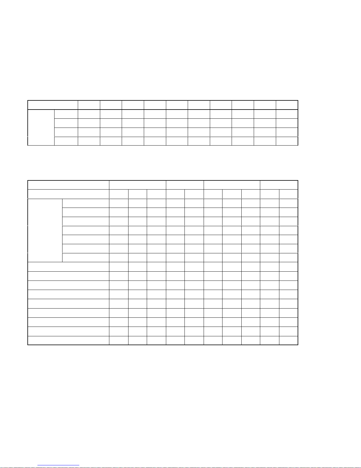
Specifiable Tool Settings
The Tool Settings items that can be set in combination with each “PT Type” and
“Direct Access” setting are indicated in the table below.
PT Type 20S 20M 600S 600M
Direct Access None Ver.4 Ver.5 None Ver.4 None Ver.4 Ver.5 None Ve r.4
Memory
32KB × × ×
f f
× × ×
f f
Size
64KB
f f
×
f f
× × ×
f f
96KB × ×
f f f
× × ×
f f
128KB × × ×
f f f f f f f
256KB × × × × × × × ×
f f
512KB × × × × × × × × × ×
1024KB × × × × × × × × × ×
Printer
f f f f f f f f f f
Sheet Feeder
f f f f f f f f f f
Mouse Use
f f f f f f f f f f
Communication Mode
f f f f f f f f f f
Communication Port
f f f f f f f f f f
Work Directory
f f f f f f f f f f
Data Directory
f f f f f f f f f f
Time [F3] × × × × × × × × × ×
Edit [F4]
f f f f f f f f f f
Page 16

xv
PT Type 30 30C 612G 620S 610C 620C
Direct Access Ver.4 Ver.4 Ver.3 Ver. 4 Ver.3 Ver.4
Memory
32KB × × × × × ×
Size
64KB × × × × × ×
96KB × × × × × ×
128KB × × × × × ×
256KB × × × × × ×
512KB
f f
×
f
× ×
1024KB × ×
f
×
f f
Printer
f f f f f f
Sheet Feeder
f f f f f f
Mouse Use
f f f f f f
Communication Mode
f f f f f f
Communication Port
f f f f f f
Work Directory
f f f f f f
Data Directory
f f f f f f
Time [F3]
f f f f f f
Edit [F4]
f f f f f f
Page 17

xvi
Functions of the Support Tool:
Things that can be done using the support tool
The support tool has the following functions.
Creation of screen data SECTION 4 Creating Screen Data....................................
Creates screen data to be displayed by an NT610C/NT612G.
Besides creating characters and graphics, lamps, touch switches, etc., as
screen data, it is also possible to allocate words for individual elements by using
the direct connection function.
Management of screen data SECTION 3 Support Tool Operations............................
Operations relating to screen data, such as the setting of screen attributes, and
copying and deletion in screen units, are possible.
File management SECTION 3 Support Tool Operations......................................
Screen data can be managed in file units.
Data communication with the PT SECTION 7 Data Communication............................
The PT can be connected to the support tool for communication of screen data
files and other types of data.
Printing data SECTION 6 Printing Data.....................................................
Screen data, memory table data, etc., can be printed out at a printer.
Environmental settings SECTION 3 Support Tool Operations.................................
The parameters of the working environment, such as the PT model and data
memory capacity, can be set.
Creating files from screens SECTION 3 Support Tool Operations.............................
Screen data can be saved in Microsoft Windows (TM) files (BMP format)
Reading files created
with other available drawing software SECTION 5 Creating Marks, Images, and Library Data....
Reading BMP files
Image files (BMP format) created using packages such as Microsoft Windows
(TM) Paintbrush can be read as data.
Page 18
xvii
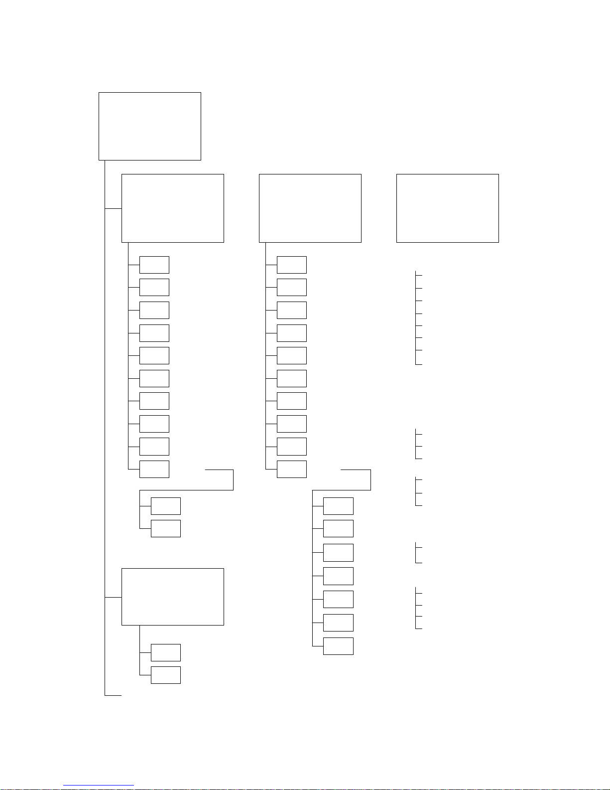
Menu Tree
Main Menu
* This comprises the function keys F1 through F10.
File Settings
F1
F2
F3
F4
F5
F6
F7
F8
F9
F10
F1
F2
F3
F4
F5
F6
F7
F8
F9
F10
Copy
Scr list
Prev
Delete
Print
ToolS
Hist.
Tmx.
Rcv.
In.Scr
Title
Next
ROMF1
F10
F1
F2
F3
F10
Copy
Delete
Print
Attrib
Read
Commnt
Co/Ovl
Mark
Next
Check
Prev
F3
F4
CoFile
Edit
Tool Settings
Edit
Time
Exit
[Setting Items]
PT Type
Memory Size
Direct Access
Direct Macn Type
Printer
Sheet Feeder
Mouse Use
Communication Port
Communication Mode
Work Directory
Data Directory
[Setting Items]
Fixed display
Character input (p.80)
Mark display (p.82)
Polyline (p.84)
Square (p.86)
Polygon (p.88)
Circle, arc (p.90)
Fan (p.92)
Tiling (p.93)
Numeral display (p.96)
Character-string display (p.98)
Lamp setting (p.100)
Touch switch setting (p.105)
Graph creation (p.117)
Bar graph
Trend graph
Broken-line graph
Input setting (p.128)
Data input
Keyboard display
User ten keys
Extended I/O settings (p.140)
Image library data display (p.141)
Memory table edit
Numeric values
Character-strings
Alarm list setting (p.144)
Screen data editing (p.150)
Copy
Move
Delete
Centering
Environmental settings (p.59)
Direct
(p.26) (p.31)
(p.22)
Image & Lib
F4 BchChg
F6 Tmx.
F7 Rcv.
Page 19

xviii
Page 20

1
SECTION 1
Setting Up the Support Tool
When using the support tool for the first time, the support tool system has to be installed in the personal computer you are
using.
This section describes the environment in which the support tool can be used and the method for installing it in a personal
computer.
1-1 Preparing Equipment 2..........................................................
1-1-1 Equipment to be Prepared 2................................................
1-1-2 Before Starting Preparations 3...............................................
1-2 IBM PC/ATPreparations 4.......................................................
1-2-1 Installation Method 4......................................................
Page 21

2
Preparing Equipment
Section 1-1
1-1 Preparing Equipment
The following equipment and materials must be prepared in orderto use thesupport tool.
1-1-1 Equipment to be Prepared
Software
S NT Series Support Tool (Type NT-ZA3AT-EV2)
This software comes in the form of a 3.5 inch floppy disk.
S DOS
IBM DOS, Ver.5.02 or later version is required.
Hardware
S IBM PC/AT Personal computer
At least 640 Kbytes of main memory is required.
Use an IBM personal computer or 100% compatible.
S At least one floppy disk drive (2HD format type)
There must be one 3.5 inch drive.
S Display
VGA compatible display
When creating screen data for an NT30C/NT610C/NT620C,a color displayis re-
quired.
S Mouse
Serial mouse or bus mouse
A Microsoft mouse driver is required.
[Common Items]
S Printer
EPSON ESC/P printer (24 pin) or HP LASER Jet.
S Hard disk drive
A hard disk is essential. The available area required forthe support toolfiles and
data area is 2 Mbytes.
Page 22
3
Preparing Equipment
Section 1-1
S Using the EMS (expansion memory)
The EMS must be loaded to the support tool before using it.
DEVICE=EMM386.SYS /F=C000
Equipment Relating to Transfer of Screen Data
S RS-232C connecting cable
For the cable specifications, see Section 7Data Communication, and the Appen-
dix.
Recommended environment
For convenience, you are recommended to use the NT series support tool inthe
following environment.
Support tool installationsite : Hard disk
Work directory (tool settings) : RAM disk
Data directory (tool settings) : Hard disk
For details on “tool settings”, see 3-3 “Tool Settings” Screen (p.22).
Note Back up the data stored in the hard disk in a floppy disk.
1-1-2 Before Starting Preparations
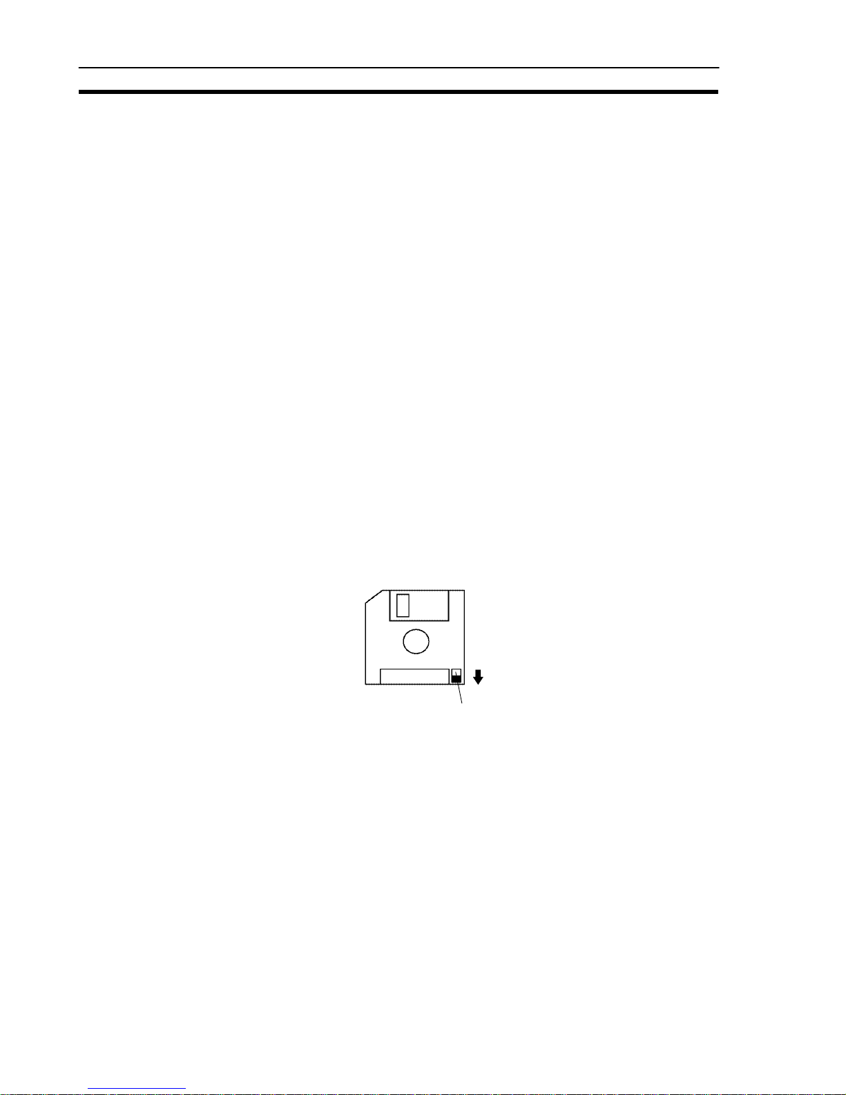
Besure tomake a back-up disk forthe support toolsystem diskand keepthe original somewhere safe.
When making the back-up, ensure that the original disk is write-protected, as
shown below:
Write-protection tag
Page 23

4
IBM PC/AT Preparations
Section 1-2
1-2 IBM PC/AT Preparations
To enable the support tool to be run on your IBM PC/AT, install the system in its
hard disk by using thesupport tool installation program.
1-2-1 Installation Method
Explained here is the method for installing the system in a harddisk that already
has a history of use.
Check that the following conditions are satisfied.
S IBM DOS (Version 5.02 or later) is installed.
S [FORMAT.EXE] and [DISKCOPY.EXE] are loaded.
If these files are loaded in a subdirectory, set an environment variable PATH.
For the purposes of this explanation, the drive configuration is assumed to be as
follows:
Drive A: 3.5 inch floppy disk
Drive B: 3.5 inch floppy disk
Drive C: Hard disk
If the drives of the system you are using differ from those in this example, rename
the drive names in the example to achievecorrespondence with your system(remember that there must be at least one 3.5 inch floppydisk drive).
Procedure 1. Start up the personal computer that has DOS installed in its hard disk.
2. Prepare a new floppy disk and use it to create a back up disk for the support
tool system disk in thefollowing way.
Set the new disk in the B drive.
Enter “FORMAT B:
”. The new disk will be formatted.
On completion of formatting, set the support tool system disk in the A drive.
Enter “DISKCOPY A: B:
”. The back up disk will be created.
" If thedisks in drive A and drive B are of different types,use the command
“DISKCOPY A: A:
” and create the back up disk in the same drive.
Now take the original disk outof the A drive and store it, and transfer the back
up disk to the A drive.
3. Use the command “A:
” to set the current drive to “A”.
4. Enter “INSTALL C: \NT
”.
The underlined part (\NT) is the directory in the hard disk to whichthe support tool
is copied; if it does not exist already it is created automatically. It is possible to
specify another directory name.
Page 24

5
IBM PC/AT Preparations
Section 1-2
If a directory that already exists is specified, the support
tool system will becopied tothat directory with no request
for confirmation. Make surethat no necessary files willbe
overwritten.
5. When the message indicating completion is displayed, the installation work is
finished.
D Notes on Installation
S Aharddisk withanavailablecapacity ofatleast 2Mbytesis requiredinorder to
installthe NTseries supporttool. If awork directory forthe supporttool is to be
created on the harddisk, anadditional capacity ofup to 2Mbytes willalso be
required.
S Start installation after securing sufficient availablecapacity.
D Available Capacity Required to Run the NT Series Support Tool
S At least 445 Kbytes (455000 bytes) of available main memory capacity isre-
quired to run the NT series support software (NT.EXE).
D Checking AvailableMain Memory Capacity
S Check the available main memory capacity either by using CHKDSK.EXE or
MEM.EXE, which are included in the DOS package.
S Input “CHKDSK.EXE” or “MEM.EXE” at the command line to display the
memory capacity and other data. If the “usable memory” or “maximum
executable program size” is 445 Kbytes (455000 bytes) or greater, NT.EXE
can be used.
WARNING
Page 25

6
IBM PC/AT Preparations
Section 1-2
Page 26

7
SECTION 2
Basic Operations of the Support Tool
Thissection explainsthe basicoperations that applyto the support tool asa whole, suchas those for starting upand exiting the
support tool, and operations using the keyboard and mouse.
When using the support tool, “help messages” which explain the operating procedures are displayed on the screen. After
becoming familiar with the basic operations by reading this section, you will therefore be able to use the support tool by
following the help messages.
2-1 Starting Upand Exiting the Support Tool 8..........................................
2-1-1 Start-Up Procedure 8......................................................
2-1-2 Exit Procedure 9.........................................................
2-2 Basic Operating Procedures 10.....................................................
2-2-1 Cursors 10...............................................................
2-2-2 Selecting Options 11.......................................................
2-2-3 Using the Function Keys 11.................................................
2-2-4 Using the Mouse 12........................................................
2-2-5 Using Help Messages 15....................................................
2-2-6 Selecting Numbers and Codes 16.............................................
Page 27
8
Starting Up and Exiting the Support Tool
Section 2-1
2-1 Starting Up and Exiting the Support Tool
This section describes the procedure for starting up the support tool once it has
been installed ina personal computer.
2-1-1 Start-Up Procedure
Themethod forstart-up differsa littleaccording tothe hard disk driveand directory
in which the support tool is installed.
Procedure 1. Switch on the power supply to the personal computer to start up DOS.
Check that the currentdrive isthe drivefor the harddisk inwhich the support
tool is installed.
If it is not, enter “C:
” to change the current drive. For the underlined part
(C:), specify the drive name ofthe drive in which the support tool is installed.
2. Usethe command“CD \NT
”to changethe currentdirectory to the directo-
ry that contains the support tool. For the underlined part (\NT), specify the
name of the directory into which the support tool was copied.
3. Input “NT
”.
The support tool will start up.
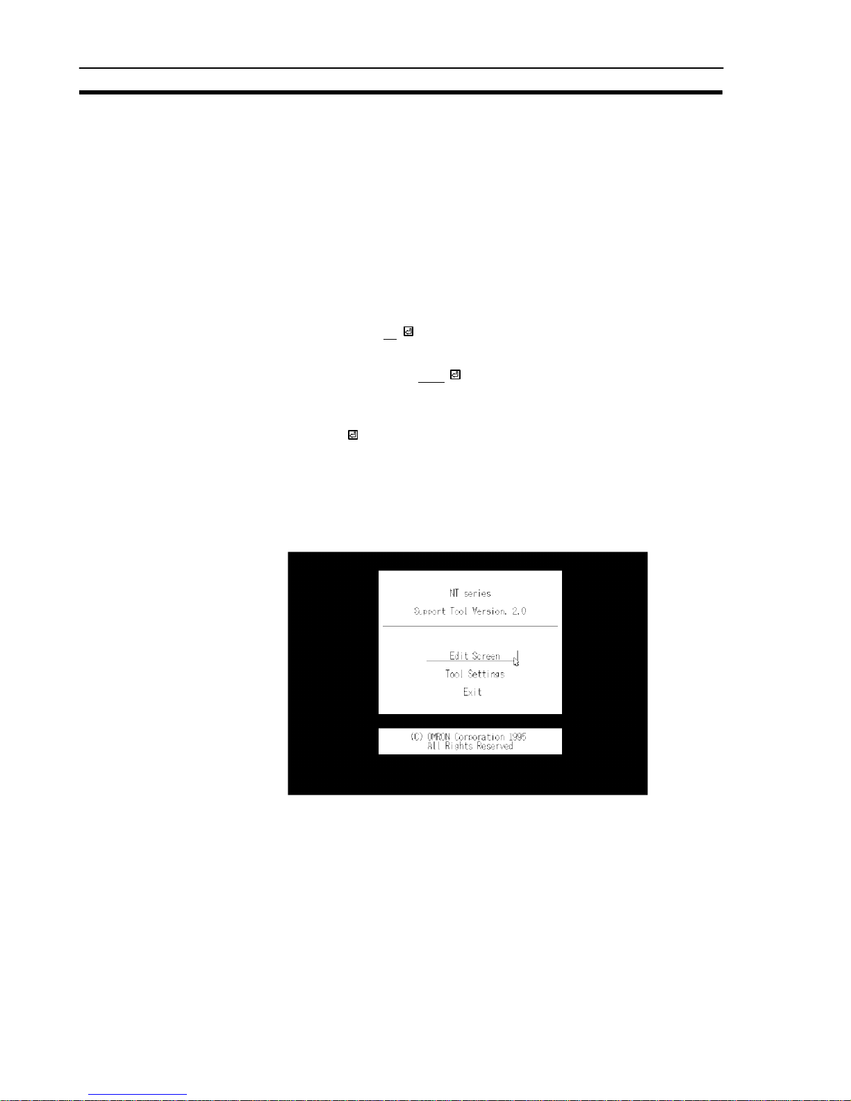
S “Main Menu” screen of thesupport tool
When the support tool starts up the “Main Menu” screen shown below will be
displayed.
Reference: When the support tool is started upfor thefirst time, the “Tool Settings”screen is
displayed first. See 3-3 “Tool Settings”Screen (p.22).
Page 28

9
Starting Up and Exiting the Support Tool
Section 2-1
2-1-2 Exit Procedure
Whenthe “Main Menu” screen is displayed, move the cursor to “Exit” using the []
[] keys and press enter key (
).
The support tool will be exited and the DOS prompt will be displayed.
After the prompt has appeared, switch the power off.
Page 29

10
Basic Operating Procedures
Section 2-2
2-2 Basic Operating Procedures
Thesupport toolis asoftware package thatallows thecreation ofscreen data fora
PT, and communication with a PT, usingsimple operations. The user canperform
these operations simply byfollowing the help displaysthat appear onthe screen.
Supporttool operationscan beperformed eitherby usingthe keyboardor byusing
a mouse.
This section explains basic operations such asthe selection of menu options and
operation of the mouse.
2-2-1 Cursors
The following types of cursor are displayed on the screen in different circumstances.
S Bar cursor (
), box cursor ( ), check box ( )
Used to select options, file names, etc.
This cursor is moved by using the [][][ ][] keys or the mouse.
S Mouse cursor (
)
Thiscursor follows the motionof themouse. Whenperforming operations using
the mouse, locatethis cursor on the requireditem andclick the left mouse button.
S Cup cursor (
)
This cursor is displayedwhile the support tool iscarrying out processing. When
the processing is finished it changes into the mouse cursor.
S Enquiry cursor (
)
This cursor is displayed while the support tool is waiting forthe inputof areply,
such as YES/NO. When this cursor is displayed, press the
key (for YES) or
the [Esc] key (for NO).
When using the mouse, press either the left button (for YES) or theright button
(for NO). It is also possible to clickon iconswith the pointedpart of the enquiry
cursor (at its top left corner) (p.12).
S Key input prompt cursor (
)
This cursor is displayed when input is required. When it is displayed,carry out
input from the keyboard or by using the mouse.
Page 30
11
Basic Operating Procedures
Section 2-2
2-2-2 Selecting Options
When performing operations using the support tool it will be necessary to select
menu options, choices, file names, etc.
Such selections are made by locating the bar cursor on the item to be selected by
using the arrow keys ([][][ ][ ] keys) and pressing the
key.
Move using [ ][ ]
Move using [][]
\
\
Items which cannot be selected are displayed inred.
2-2-3 Using the Function Keys
Thecurrently available functionsand currently selectable options are displayed at
the bottomof the screen. The items displayed correspond to the function keys on
the keyboard. Toexecute one ofthe displayed options, press thefunction key on
the keyboard that corresponds to it.
F1 F2 F3 F4 F5 F6 F7 F8 F9 F10
Page 31

12
Basic Operating Procedures
Section 2-2
2-2-4 Using the Mouse
It is possible to perform all the support tool operations by using a mouse.
Theleft button ofthe mouse has the same function asthe
key on the keyboard
and right button the same function as the [Esc] button.
Selection or specification of itemsusing themouse is achievedby clickingone of
its buttons. “Clicking” means pressing the button and releasing it immediately.
Clicking with the left mouse button is sometimes called “left clicking” and clicking
with the right mouse button is sometimes called “right clicking”.
S “Mouse Use” specification
Whether the mouse is used or notis specifiedwith the“Mouse Use” optionof the
“Tool Settings” menu (seep.22). If “No”is specified,the mouse cursor ceases to
be displayed (however, even if “No” is specified, the mouse cursor will be displayed and will be able to beused when editing image data).
S Selection
Select items by moving the cursor to them and clicking on them.
Forexample, toselect a file, locatethe mouse cursor at theintended filename and
click the left mouse button. When thebar cursor has moved, click on the filename
again with the left button. This will select the file.
Clicking on an input field has the same effect as pressing the
key.
S Icon operations
The key marks displayed in thehelp messagearea andelsewhere are iconsthat
canbe actuatedwith themouse. Clickingon anicon with theleft mousebutton will
execute the function represented by that icon.
For example, clicking on the [SPACE] mark displayed on the screen with the left
mouse button will have the same effect as pressing the
key.
Click on the
mark with
the mouse.
Icons
Page 32

13
Basic Operating Procedures
Section 2-2
S Operations on the editing screen
When specifying coordinate positions etc. on the editing screen, the cross-hair
cursor (intersecting vertical and horizontal lines) is displayed. The cross-hair cursor follows the motion of themouse. To fix a position,click theleft mouse button.
Cross-hair cursor
When the cross-hair cursor touches the menu box, the menu box isautomatically
cleared from the screen and coordinates are displayed at the top right of the
screen. Whentheoperation withthe cross-haircursor is completed,the menu box
is redisplayed.
Whetheror not a menu box is displayedwhen the cross-hair cursor is displayed is
specified in the “environmental settings” (tool settings for the “Edit” screen).
S Double click
To specify the end points for continuous lines and polygons, double-click the
mouse. “Double-clicking”meanspressing theleft mousebuttontwice in rapidsuccession.
Page 33

14
Basic Operating Procedures
Section 2-2
S Moving the bar cursor
When screens or display elements are displayed in a list, the bar cursor can be
moved by clicking at entries above or below the current cursor position.
Clicking here causes the bar
cursor to move downward.
Bar cursor
Clicking here causes the
bar cursor to move upward.
Page 34

15
Basic Operating Procedures
Section 2-2
2-2-5 Using Help Messages
The support tool is provided with “help messages” for each screen: they display
thekey operations that cancurrently be used, or prompt parameterinput or selections.
Thekey displays inthe helpmessage area also function asicons that canbe actuated using the mouse.
Operate the support toolby following the helpmessages. There are two typesof
help message, distinguishedon the basis of the screen and function, as indicated
below.
S Help messages that display the operating procedure
Usually, as shown in the screen below, the operation keys that can be used with
the current screen, and their details, are displayed in the help message area.
Operation help message
The key, cursor keys, [Page Down], [PageUp], etc., canbe usedeven if they
are not displayed.
S Help messages for parameter input
In cases such as when a function has beenselected witha function key, settings
and parameters can be specified in the help message area.
Page 35

16
Basic Operating Procedures
Section 2-2
2-2-6 Selecting Numbers and Codes
The support tool allows simple selection of the following numbers and codes.
S Screen numbers
S Numeral table numbers
S Character-string memory table numbers
S Bit memory table numbers
S Image codes
S Library codes
S Extended I/O input terminal numbers (*)
S Extended I/O output terminal numbers (*)
(*) Only number specification using the [Tab] key can be used for these.
Whenascreen thatdisplays alist of numbersor codesis displayed,the keyopera-
tions indicated below can be used:
[Shift] + [] key : Moves the bar cursor from the position where it is currently
located to the previous number or code for which there is
data.
[Shift] + [] key : Moves the bar cursor from the positionwhere it is currently
located to the next number or code for which there is data.
Example:
Assumethat thebar cursoris onscreen number6 andthere isdata onlyfor screen
numbers 2, 4, and 10:
[Shift] + [] key : The bar cursor moves to screen number 4.
[Shift] + [] key : The bar cursor moves to screen number 10.
If now, while the barcursor is at screen number10, [Shift]+ [] is pressed again,
the bar cursor will move full cycle to screen number 2.
Page 36

17
Basic Operating Procedures
Section 2-2
[Tab] key : The number/code inputfield is displayed. When a numberof
code is input and the
key pressed, the bar cursor moves
to the specified number or code.
Example: Screen number input field
Page 37

18
Basic Operating Procedures
Section 2-2
Page 38

19
SECTION 3
Support Tool Operations
The support tool has the following 5 screens: the “Main Menu” screen, the “Tool Settings” screen, the “File Selection”
screen, the “Screen Selection” screen, and the “Edit” screen. This section describes the four screens other than the “Edit”
screen.
3-1 Using the Support Tool 20........................................................
3-2 Main Menu 21.................................................................
3-3 “Tool Settings” Screen 22.........................................................
3-4 “File List” Screen 26............................................................
3-5 “Scr list” Screen 31..............................................................
3-5-1 Functions of the “Scr list”Screen 31..........................................
3-5-2 Setting Direct Connection Information 42......................................
Page 39

20
Using the Support Tool
Section 3-1
3-1 Using the Support Tool
The support tool is a software package for creating screen data and transferring it
to a PT.
The support tool has five basic screens and on these five screens it is possible to
create data, and to select various functions and execute them.
The relationships between the screens are shown below.
Support Tool Startup/Exit
Main Menu
“File List” screen
Used to select screen data files.
Permits various file-related operations.
“Tool Settings” screen
Used to set the environmental
settings for the support tool, such
as the PT model used.
Communication with the PT
Execute communication of
screen data etc. with the PT.
Print
Print screen data, conditions of use
of memory tables, etc., at a printer,
or store them in files.
“Screen List” screen
Used to select screen data.
Screen data attributes can be set
and various operations relating to
screen data are possible.
“Edit” screen
Used to create screen data using
characters and graphics.
Reference: When the support tool is started up for the first time, the “Tool Settings” screen is
displayed first.
Page 40

21
Main Menu
Section 3-2
3-2 Main Menu
When the support tool is started up, the “Main Menu” screen is displayed first.
The items in the main menu have the following functions.
S Edit Screen: Select this item to create or edit screen data. The “File Selection”
screen will be displayed and operations relating to screen data
and files will be possible.
S Tool Settings: Used to set the environmental conditions for using the support
tool, such as the model of the PT used in conjunction with the support tool, the image data memory capacity, and the model of printer used. Provided there are no changes, these settings only have
to be set once.
S Exit : Used to exit the support tool. To exit, select this item, wait for the
DOS prompt to be displayed and then switch the power off.
Page 41

22
“Tool Settings” Screen
Section 3-3
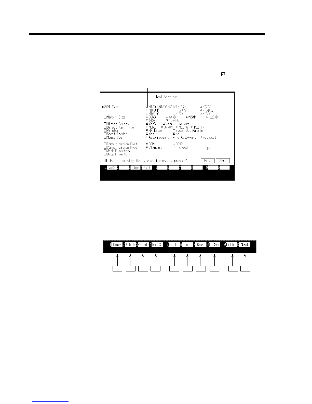
3-3 “Tool Settings” Screen
This screen is used to set the environmental settings required to use the support
tool, such as the PT model, capacity of the screen data memory board, and the
directory in which data is saved.
When using the support tool for the first time, this screen is displayed first. Be sure
to set the tool settings in accordance with the model you are using. After this first
setting, it will not be necessary to set the tool settings again unless there is some
change.
Settings When “Tool Settings” is selected from the main menu, the “Tool Settings” screen is
displayed. For details on the permissible combinations of settings, see “PT Model
and Tool Settings” (p.xiv) at the beginning of this section.
<“Tool Settings” screen>
\
\
S PT Type: Specify the model of PT being used.
Note The specified PT Type setting is different from the actual PT model in the following
cases:
NT20S-ST121 (without [-V1]): [NT20M]
NT612G: [NT610G]
NT620S: [NT610G]
NT620C: [NT610C]
S Memory Size: Specify the capacity of the screen data memory
board installed in the PT.
S Direct Access: Specify the direct connection version. If not using
the direct connection function, set “Ver.4” for the
NT20S, NT20M, NT600S, and NT600M. “NONE”
cannot be set for NT612G/610C or NT620C/S.
S Direct Macn Type: Set “NONE” if direct connection is not used. Set
“OMRON” if direct connection is used.
Page 42

23
“Tool Settings” Screen
Section 3-3
S Printer: Specify the type of the printer used to print screen
data, etc., here.
S Sheet Feeder: Specify whether or not the printer is fitted with a
sheet feeder here.
S Mouse Use: Specify whether or not a mouse is used with the sup-
port tool, and, if a mouse is used, the operation when
the mouse is used.
If “Auto movement” is selected, the mouse cursor
moves automatically when a window or other screen
display for making setting is displayed, speeding up
input and specification operations. If “No
AutoMvmnt” is selected, the mouse cursor does not
move automatically. However, the mouse cursor is
displayed, and can be used, during image data
editing, even if “Not used” is set.
S Communication Port: Specify the port on the computer to be used to com-
municate with the PT. If possible, do not specify the
same port as the one used for the mouse.
S Communication Mode: Set the communication speed for communication of
data with the PT.
Set “Stndrd” if the conditions for communication are
unfavorable due to interference, etc.
S Work Directory: The support tool temporarily creates work files for
data creation and communication, etc. This setting
specifies the directory in which work files can be
created.
S Data Directory: Specify the directory in which created screen data
files are saved here.
Reference: S The NT series support tool is compatible with all OMRON PT models, all
versions of the direct connection function (Ver.3, Ver.4, Ver.5), and the
communication methods other than direct connection. The support tool displays
and selectable functions differ according to the settings made for “PT Type”,
“Direct Access”, and “Direct Macn Type”.
S For details on the direct connection function, refer to the user’s manual for the
relevant host interface unit.
S The specified “PT Type”, “Memory Size”, “Direct Access”, and “Direct Macn
Type”, are displayed on each screen as shown below.
Page 43

24
“Tool Settings” Screen
Section 3-3
Example
File Selection screen when “612G”, “512B”, and “Ver.3”, respectively, have been
set for these items.
File List NT610G
−V3−O 512KB
PT Type (PT model name)
Direct Access (Direct connection version)
V3 = “Ver.3”
V4 = “none”
*
or “Ver.4”
V5 = “Ver.5”
Direct Macn Type (Direct model)
O = PC made by OMRON
Noting displayed = Direct connection
not used
Memory size
*: For “20M”, “20S”, “600M”, “600S”
Functions of the function keys
[TypSel] [F1] Direct connection setting for PT model...
Used to set the “Direct Access” based on the model of PT or system ROM. Since
the settings for “PT Type”, “Memory Size”, “Direct Access” and “Direct Macn Type”
differ according to the PT and the system ROM used, selection based on the model makes it possible to set all the settings for “PT Type”, “Memory Size”, “Direct
Access” and “Direct Macn Type” at the same time.
(1) Press the [F1] (TypSel) key. The window shown below will be displayed. The
communication methods that can be used are also displayed for your reference.
When the window is displayed by pressing [F1] (TypSel), the bar cursor is located at the PT model which was set for “PT Type”.
(2) Select the model of PT/system ROM being used.
(3) Press the
key. The “Tool Settings” screen will be redisplayed with the “PT
Type”, “Memory Size”, “Direct Access” and “Direct Macn Type” settings that
can be used with the selection made in step (2) set.
Page 44

25
“Tool Settings” Screen
Section 3-3
[Time] [F3] PT time setting...
Used to make the time setting for the PT. The time function can be used with the
NT30, NT30C, NT612G, NT610C, NT620S, NT620C.
(1) Connect the PT and the support tool (see Section 7 Data Communication).
(2) Press the [F3] (Time) key.
(3) To change the current time, enter the time on the screen.
(4) Set the PT to the “Transmit Mode”.
(5) Press the
key: the time data will be sent and set in the PT.
" It is also possible to receive the time set in the PT and set it. Press the [F1]
(receive) key with the time setting screen displayed.
[Edit] [F4] Tool settings for the “Edit” screen (environmental settings)...
Used to set the “Edit” screen settings, such as grid display and “snap ON” setting.
These settings can also be made by selecting SET ENV on the initial editing
screen. For the details of these settings see “Environmental Settings” (p.59).
Quitting tool setting
S Press
key twice: the support tool will be set in accordance with the details
displayed on the screen and the display will return to the main menu.
S Press the [Esc] key to return to the main menu without making any settings.
Page 45

26
“File List” Screen
Section 3-4
3-4 “File List” Screen
When the “Edit Screen” option is selected from the main menu, the “File List”
screen is displayed.
In support tool terminology, an assemblage of screen data is called a “file”.
Actually, each “file” comprises four or five files with different extension names (the
number of files per “file” depends on the “tool settings”).
Settings On the “File List” screen, besides creating and selecting files, it is also possible to
perform functions such as data communication with the PT.
<“File List” screen>
(a) (b) (c)
(d)
(f)
(e)
(g)
(a) PT model name: This is the PT model and direct connection ver-
sion number set in the “Tool Settings”. The final 0
indicates direct connection. Even if direct connection is not used, the version is displayed as “V4”
when using an NT20M, NT20S, NT600M, or
NT600S.
(b) PT memory size
(c) Name of task currently being executed
(d) Help message area: Displays a guide to operation and allows parame-
ter input.
(e) File name: The file names are indicated in this column. If the
bar cursor is located on a file name and the
key pressed, the “Screen Selection” screen will be
displayed. To create a new file, select
“NEW_FILE”.
(f) Title: This is a comment that indicates the contents of a
file. It is input when the file is saved.
Page 46

27
“File List” Screen
Section 3-4
(g) File information: The NT model, direct connection version, direct
connection indication, and file size for the file at
which the bar cursor is located are displayed here.
Even if direct connection is not used, the version
is displayed as “V4” when using an NT20M,
NT20S, NT600M, or NT600S.
The support tool allows the creation of up to 200 “files” (the number may be smaller
than this due to restrictions on the number of files per DOS directory). If the required file is not displayed on the screen, screens earlier and later in the sequence
can be displayed by using the [Page Down] and [Page Up] keys, or icons.
Depending on the direct connection version of the model used, it may or may not
be possible to use certain files.
Files that cannot be used are displayed in red.
To use more than 200 files, create another directory. The data directory can be
changed by using the “Tool Settings” option.
All the files in the specified data directory are displayed.
The files that correspond to the “PT Type” and “Direct Access” set in the “Tool
Settings” are first in the order of display. The other files are displayed in the following order: 20M, 20S, 600M, 600S, 612G, 610C, 30, 30C; files corresponding
to the same model are displayed in order of direct connection version.
It is possible to read files set using other models but you are advised to check the
details of the file information displayed when the file is specified before reading it.
It is also possible to read files created using previous support tool versions.
Returning to the main menu
To return to the main menu, press the [Esc] key.
Functions of the Function Keys
[Copy] [F1] Copy file...
Used to copy the contents of a file to another file (copying in support tool “file”
units).
(1) Press the [F1] (copy) key.
(2) Select the file to be copied.
(3) Input the file name and title of the copy destination and press the
key.
" If [F1] (drive) is now selected, the file can be copied to the directory of another
drive.
[Delete] [F2] Delete file...
Used to delete unnecessary files (deletion in support tool “file” units).
(1) Locate the bar cursor at the file to be deleted and press the [F2] key.
(2) Check the file name and then press the
key: the file will be deleted.
Page 47

28
“File List” Screen
Section 3-4
[Print] [F3] Print data...
Used to print out files, information relating to screen data, character-strings, the
conditions of use of numeral tables, etc.
See Section 6 “Printing Data”.
[Tools] [F4]] Tool settings...
Displays the “Tool Settings” screen.
Used to change the support tool environment during file operations.
For details of the setting operation, see 3-3 “Tool Settings” Screen (p.22).
[Hist.] [F5] Receive display history registration data...
Used to read display history registration data registered in the PT and save it in a
file.
This file is a text style of DOS format file and is therefore different style from the
files in which screen data is saved.
See Section 7 “Data Communication”.
[Tmx.] [F6] Send data to the PT...
Establishes a connection with the PT, sends created data to it in file units and
writes it to the image data memory. The types of data that can be sent are screen
data, character-string memory table and numeral table data, system memory
data, mark data, image data, library data, and direct information.
See Section 7 “Data Communication”.
[Rcv.] [F7] Receive data from the PT...
Used to receive data registered in the PT in file units. The types of data that can be
received are screen data, character-string memory table and numeral table data,
system memory data, mark data, image data, library data, and direct information.
See Section 7 “Data Communication”.
[In.Scr] [F8] Set system memory...
Used to set the screen number and PT statuses at startup that are displayed when
the PT is started up.
Page 48

29
“File List” Screen
Section 3-4
The following items can be set:
Initial screen
Number of the screen data displayed when the
PT is started up.
(Invalid when direct connection is used)
Supported by all
NT models
Key input buzzer ON/OFF status of key input sound.
Supported by
Buzzer Buzzer sound ON/OFF or ON only when an
error occurs.
NT30, NT30C,
NT612G, and
Resume function ON/OFF status of the “resume” function.
NT610C
only
.
Alarm output ON/OFF status of alarm output.
Backlight OFF
(prevention of
afterimage)
This is an afterimage prevention function which
automatically switches off the backlight (or
makes the display blank). The available
settings are to switch the backlight off after a
time lapse of 10 minutes/1 hour, or “off”. With
an LED screen, this function switches the
backlight OFF. With an EL screen, it makes the
screen blank.
Printer: Type of printer connected to the PT: EPSON
Esc/P printer (24 pin) or HP LASER Jet.
Print way Printing method used when printing a screen
displayed on the PT: color or grayscale (only
valid when using NT30C and NT610C).
Numeral tables The number of numeral tables: 512 or 1000 (if
reduced to 512, the memory capacity available
for screen data is increased by 4880 bytes).
String tables The number of character-string memory tables:
256 or 1000 (if reduced to 256, the memory
capacity available for screen data is increased
by 29760 bytes).
Alarm fast I/O Processing method when the maximum number
of alarm instances (256) is exceeded when
using the alarm history.
“Yes” Old records are deleted as new ones
are registered.
“No” The registration of new history records
is prevented.
On completion of setting, press the key.
Page 49

30
“File List” Screen
Section 3-4
[Title] [F9] Change file title
Used to change the titles of files for which titles have been set.
(1) Locate the bar cursor at the file whose title is to be changed and press the [F9]
(Title) key.
(2) Enter the new title and press the
key.
[Next] [F10] Display next function keys..
Pressing this key changes the function key display to the next set of function keys.
The functions of these function keys are explained below.
[ROM] [F1] Data communication with P-ROM writer...
Used to communicate with a P-ROM writer in order to create or modify EP-ROMs
for image memory boards.
[Prev] [F10] Display previous function keys..
Pressing this key changes the key display to the previous set of function keys.
Page 50

31
“Scr list” Screen
Section 3-5
3-5 “Scr list” Screen
The “Scr list” screen is displayed when a file to be edited is selected from the “Select File” screen, or when NEW_FILE is selected.
3-5-1 Functions of the “Scr list” Screen
Settings Besides specifying the screen number for which screen data is to be created, vari-
ous other operations and settings relating to screen data are possible on this
screen, for example the setting of attributes for screen data and reading of data
from other files in screen units.
Select the required screen and press the
key to enable editing of the screen.
<“Scr list” Screen>
(h)
(b) (c) (d)
(i)
(j)
(a)
(e)
(g)
(f)
(a) Selected file name
(b) PT model name: The PT model name and direct connection ver-
sion for the file is displayed here. Even when
direct connection is not used, the version is
displayed as “V4” when using an NT20M,
NT20S, NT600M, or NT600S. Data for direct
connection has an “O” appended as the final
character.
(c) PT memory size
(d) Name of task currently being executed
(e) Help message area: Displays a guide to operation and allows pa-
rameter input.
(f) Screen status details: Detailed information on screen data is dis-
played here.
(g) Screen data size
Page 51

32
“Scr list” Screen
Section 3-5
(h) Screen number: The support tool manages screen data under
screen numbers. Screen data can be created
under the screen numbers shown in the table
below.
NT Model Setting
Usable Screens
20S 1 to 500
20M 1 to 250
600S, 600M 1 to 1000
30, 30C, 612G, 610C 1 to 2000
The previous and next pages can be displayed
by using the [Page Up] and [Page Down] keys.
The bar cursor can be moved to the previous
and next screen number for which there is data
by using [Shift] + [] and [Shift] + [].
The “No.” column is displayed by pressing
[Tab] key.
(i) Screen status, attribute: In the “Status” column, the presence/absence
of screen data and the set attribute are displayed in symbolic form.
More detailed information relating to these indications is displayed in the “Screen Status”
area at the bottom right of the screen.
Page 52

33
“Scr list” Screen
Section 3-5
Symbol
“Screen Status”
Information
Meaning
(Blank) (No data) No data has been created for this number.
! (Data exists) There is data for this number.
A A: Cont Parent screen of continuous screens
A A: Ovlp Parent screen of overlapping screens
B B: Cont Buzzer attribute (continuous tone)
B B: Long Buzzer attribute (intermittent long tones)
B B: Shrt Buzzer attribute (intermittent short tones)
C C: Hist Display history attribute
D D: Touch Bit input (touch switch)
D D: Fn key Bit input (function key)
E E: Alrm Alarm attribute
F F: Keys “Keypad” ten keys are set by the user.
G G: Ext NT20M, NT30 : Red backlight or flash-
ing backlight
NT20S : Flashing backlight
NT30C : Background color or
flashing backlight
NT610C, NT620C : Background color
(j) Comment: This is a comment assigned to the screen
data. It is set when the screen data is saved.
It can be changed using the [F6] (Commnt)
key.
Page 53

34
“Scr list” Screen
Section 3-5
<Screen numbers and their applicability>
When the NT Model setting is “30”, “30C”, “610G (612G)”, or “610C”, some
screens are earmarked for special applications, as shown below. When the NT
Model setting is not one of these, only “0” (clear screen display) is valid and all other screens are user screens.
Screen No.
Application User Editing Remarks
0 Screen display OFF
×
Specified in order to switch the screen display off.
1 to 1899 User screens f Can be used without restriction
1900 to 1979 Window (keyboard) screen
f
Can be used as a window (keyboard) screen
called to overlay another screen.
Can also be used as a normal screen.
1980 to 1996 Reserve screens for expan-
sion functions
f
If data is registered for these screens, treating them as normal screens, the registered
data takes priority.
1997
1998
Display history screens
1997: Order or occurrence
1998: Order of frequency
Only when using Ver.3 or a later version of
the direct connection function (necessary to
create scroll keys).
1999 “Connecting Host” screen
f
If no data is registered, the “Connecting
Host” screen set by the system is displayed.
2000 “Host Error” screen
f
If no data is registered, the “Host Error”
screen set by the system is displayed.
(Used as a user screen in the case of the
NT30, NT30C, NT620S, NT620C)
f: Possible : Only the area outside the display history display area can be edited. ×: Not possible
<Using the marking function>
When, for example, deleting screen data, a number of screens can be handled
together by using the marking function. All marked (*) screen data is taken as the
object of the executed operation, regardless of the location of the bar cursor. In a
copy operation, the screen data at the location of the bar cursor is copied to all
screen numbers marked by (*). This is useful when creating very similar screens.
[Space] key: Marks the selected screen data. If the data is already marked,
the mark is deleted.
[Home] key: Deletes all marks.
[Shift] + [Home]: Deletes the marks of all marked screen data and marks all un-
marked screen data.
Page 54

35
“Scr list” Screen
Section 3-5
To perform an operation all screens except a specified screen (or screens), use
the following procedure:
Example: Deleting all screen numbers except screens 1 to 3.
1. Clear all marks by pressing the [Home] key.
2. Mark screens 1 through 3 by pressing the [Space] key.
3. Press [Shift] + [Home].
All screen numbers except 1 through 3 will be marked.
4. Delete the screen data by pressing [F2] (Delete).
<Saving and quitting screen data files>
Pressing the [Esc] key while the “Screen Selection” screen is displayed quits
screen creation. There are two types of quitting: quitting after saving the file, and
quitting without saving the file.
key: Press after inputting the file name and comment to save the file
and return to the “File Selection” screen.
[Space] key: Used to return to the “File Selection” screen without saving the
file.
[Esc] key: Used to abort quitting and continue screen selection.
Functions of the Function Keys
[Copy] [F1] Copy screen data...
Used to copy screen data to another screen number.
(1) Locate the bar cursor at the screen data to be copied, and press the [F1]
(Copy) key.
(2) Input the copy destination screen number and comment and press the
key.
" It is also possible to batch copy all marked screen numbers.
[Delete] [F2] Delete screen data...
Used to delete unnecessary screen data.
(1) Locate the bar cursor at the screen data to be deleted and press the [F2] (De-
lete) key.
(2) Press the
key.
" It is also possible to batch copy all marked screen numbers.
[Print] [F3] Print data...
Used to print out screen images and the numbers of lamps and touch switches at a
printer.
See Section 6 “Printing Data”.
Page 55

36
“Scr list” Screen
Section 3-5
[Attrib] [F4] Set attribute...
Used to set screen attributes. Setting is accomplished by making selections in the
Help Message area. The following attributes can be set.
“NT Model” Setting
A
ttribute
P
oss
ibl
eSettings
20S 20M 600S 600M 30 30C 610G 610C
R
emarks
Buzzer
None, Cont (continuous sound),
Long (long intermittent sounds),
Shrt (short intermittent sounds)
f f f f
: Continuous
sound,
Intermittent
sounds
History No, Yes f f f f f f f f
Bit In
Off, Touch SW (touch switch),
Extd I/O
/× f/× /× f/× −/× −/× f/× f/×
Direct connection
used/not used
: F keys cannot
be set.
Alarm
No, Yes × f × f × ×
: Cannot be
used with
NT620S/
NT620C
Keypad System, User f f f f f f f f
Back light Lit, Flash f f × × f f − −
Bklt Col White, Red × f × × f × − −
Back Col Screen background colors − − − − × f × f
f: Possible : Partly possible (some restrictions apply). ×: Not possible, −: No display
For details on each attribute, refer to the Operation Manual for the PT.
The attributes of the parent screen are used in the case of
continuous screens and overlapping screens. Screen
attributes set for child screens are invalid.
Batch setting of attributes for all marked screen numbers is possible.
[Read] [F5] Read screen data...
Used to read screen data and memory table data from other files.
However, the data of files displayed in red cannot be read as it is: data conversion
is necessary (see Section 8).
(1) Press the [F5] (Read) key.
(2) Select the file whose data is to be read and press the
key.
" Pressing the [F1] (Drive) key allows the specification of a file in another drive
directory. Only files for which the “Direct Access” setting is the same can be
specified.
WARNING
Page 56

37
“Scr list” Screen
Section 3-5
(3) The procedure after this point differs according to the type of data: see the
scheme below. Specify the data to be read, the reading source and reading
destination by following the directions on the screen in order to read the data.
Confirmation of
reading execution
information of
data to be read
Screen data
Reading source
screen information
Reading destination
screen information
Overwrite/insert
information
Read execution
confirmation
Execution of reading
Mark data
All/part?
All
Read execution
confirmation
Execution of reading
Part
Reading source
range information
(start point, end point)
Read position
information
Read execution
confirmation
Execution of reading
Execution of reading
Numeral table
Character-string table
Direct connection information
I/O comment
Bit memory table
Read execution
confirmation
All/part?
All
Read execution
confirmation
Execution of reading
Part
Image data
Library data
Reading source
code information
Reading destination
code information
Execution of reading
*5 *5
*3
*2 *2
*1
*4
(*1) The following restrictions apply to the data that can be read.
Image data: “30”, “30C”, “610G”, and “610C” only.
Library data: “30”, “30C”, “610G”, and “610C”, Ver.3 or later only.
Direct connection information:
When direct connection used only.
I/O comment:
When direct connection used only
Bit memory table:
“30”, “30C”, “610G”, and “610C”, Ver.3 or later only.
(*2) When the [Tab] key is pressed and a screen number input, the bar cursor
shifts to the specified screen.
(*3) Overwrite: If data already exists at the destination it is overwritten (the
original data is cleared).
Insert: If data already exists at the destination the data is read into the
file without clearing the original data.
Page 57

38
“Scr list” Screen
Section 3-5
(*4) When direct connection is used and reading of a numeral memory table,
character-string memory table, or bit memory table is specified, confirmation of whether or not the direct connection information is read is displayed.
(*5) S Image data is selected from codes FE20 through FEFF.
S Library data is selected from FA20 through FAFF, FB20 through FBFF,
FC20 through FCFF, FD20 through FDFF.
S Use [Shift] + [] or [Shift] + [] to move the bar cursor to the previous or
next code for which there is data.
S The bar cursor can be moved to a specified code by pressing the [Tab] key
and inputting the code.
It is possible to continue reading more data from the same file.
To quit data reading, press the [Esc] key; the display will return to the “Screen
Selection” screen.
[Commnt] [F6] Change comment...
Used to change the comments assigned to screen data.
(1) Locate the bar cursor at the screen number whose comment is to be changed
and press the [F6] (Commnt) key.
(2) Input the new comment and press the
key.
It is possible to change the comments for a number of screen numbers in a
batch by marking the screen numbers. However, this only applies to screen
numbers for which data already exists.
[Image & Lib] [F7] Edit Image/library data...
Used to create and modify image library items.
Editing of images and library data is only possible with the NT30, NT30C,
NT612G, and NT610C.
See Section 5 “Creating a Mark Image Library”.
[Co/Ovl] [F8] Continuous screen & overlapping screen setting...
Used to specify continuous screens and overlapping screens.
(1) Locate the bar cursor at a screen number for which there is no data and press
the [F8] (Co/Ovl) key.
" If a number for which there is data is specified, a message asking whether or
not the data is to be cleared is displayed.
(2) Select either “Cont Scr” or “Ovlp Scr” and press the
key.
The set screen will become the parent screen.
(3) Set the child screens by following the help messages.
" Up to 8 child screens can be set in the case of both continuous screens and
overlapping screens.
" Only one numeral setting screen can be set as a child screen.
Page 58

39
“Scr list” Screen
Section 3-5
[Mark] [F9] Mark creation...
Used to create and modify marks.
See Section 5 “Creating a Mark, Images, and Library Data”.
[Next] [F10] Display next function keys..
Pressing this key changes the function key display to the next set of function keys.
Direct connection not used
Ver.1 to Ver.4 used
For an explanation of the function of each function key, see the following.
[Check] [F1] Check on continuous screens/overlapping screens...
Used to check if there is any abnormality in the relationship between the parent
and child screens of continuous screens and overlapping screens.
(1) Select the file to be selected on the “File List” screen.
(2) Press the [F10] (Next page) key and then press the [F1] (Check) key.
(3) Set whether or not the results are to be output at a printer and execute the
check.
The results of the check are displayed in the following form.
No.
Error Details
No. : The parent screen number is displayed here.
Error : If an error is found, its details are displayed.
Error Type Cause
Prnt A screen set as child screen has been specified as the parent screen for another
continuous screen or overlapping screen.
Keys
Overlapping screen There are two or more child screens for which a numeral
setting has been made (when carrying out system setting).
Continuous screen There is a child screen for which a numeral setting has been
made.
Num Overlapping screen In direct connection, the total of the numbers the following
functions exceeds the maximum number that can be set.
Number of functions settable:
Numeral displays + graphs + numeral settings = Max. 1024
Attr Overlapping screen The “keypad attribute” is different for the parent screen and
child screens.
Page 59

40
“Scr list” Screen
Section 3-5
Details: The numbers of the child screens that make up the overlapping
screen or continuous screen are displayed.
If there is an error, the relevant screen number is underlined.
If screen numbers in the range 1900 to 1979 are specified as parent screens,
“No.” will be displayed in red. These screens cannot be used as window
screens.
[Table] [F2] Edit table (when not using direct connection)...
Used to write data to, and change the data in, character-string memory tables and
numeral memory tables.
(1) Press the [F2] (Table) key.
(2) Select the character-string memory table or numeral memory table and press
the
key.
(3) Edit the contents of the memory table.
S Move the bar cursor with the arrow keys, make the selection by pressing the
key, and change the data.
S Previous and next screens can be displayed by using the [Page Up] and [Page
Down] keys.
S The bar cursor can be moved to a specified number by pressing the [Tab] key
and inputting the number.
S Pressing the [F1] (Ref) key will display a list of the screens that refer to the
memory table with the specified number. When editing a character-string
memory table, marks can be input using [F3] (Mark) and images using [F4]
(Image).
(4) To quit editing, press the [Esc] key.
[Direct] [F2] Set direct connection information (when using direct connection)...
Data area allocations for direct connection can be made using batch settings.
See “Setting Direct Connection Information” (p.42).
[CoFile] [F3] Creating files from screens...
Screen data can be saved in Microsoft Windows
(TM)
files (BMP format)
Files are created under the following file names in the data directory.
20S, 600S: NTSVVVV.BMP
20M, 600M: NTMVVVV.BMP
612G: NTGVVVV.BMP
30C, 610C: NTCVVVV.BMP
VVVV indicates the screen number.
[BchChg] [F4] Batch change of screen data bits and words...
Used to change bits and words allocated to lamps and touch switches in the
screen data in a batch by specifying a range.
See “Batch Changing Bits and Words” (p.79).
Page 60

41
“Scr list” Screen
Section 3-5
[Tmx.] [F6] Send data to the PT in screen units...
After connecting the support tool to the PT, used to send screen data, characterstring and numeral memory tables to the PT in screen units and write them to the
screen data memory.
See Section 7 “Data Communication”.
This function cannot be used with the NT30, NT30C, NT612G, or NT610C.
[Rcv.] [F7] Receive data from the PT in screen units...
Used to receive screen data and character-string/numeral memory table data registered in the PT.
See Section 7 “Data Communication”.
This function cannot be used with the NT30, NT30C, NT612G, or NT610C.
[Prev] [F10] Display previous function keys..
Pressing this key changes the key display to the original set of function keys.
Page 61

42
“Scr list” Screen
Section 3-5
3-5-2 Setting Direct Connection Information
The “Direct Spec. Setting” menu option on the “Screen List” screen allows batch
setting of the following functions:
S PT status control area allocation
S PT status notify area allocation
S Numeral table allocation and initial value setting
S Character-string table allocation and initial value setting
S Extended I/O unit input terminal allocation and function setting
S Extended I/O unit output terminal allocation
S Setting of the functions, display, and allocations of bit memory tables
“Bit memory table” can only be selected when the NT
Model setting is NT30, NT30C, NT612G, or NT610C, and
the direct connection version used is Ver.3 or later.
Note Be sure to allocate the data area referenced in the PC to the PT status control area
and PT status notify area. Allocate these two areas so that they do not overlap.
Procedure 1. Press the [F10] (Next) key on the “Screen List” screen.
2. Press the [F2] (Direct) key.
3. Locate the bar cursor at the function to be set and press the
key.
The function setting window will be displayed: carry out allocations to the data
area in the PC and function setting in this window. For details of the settings,
refer to the descriptions of the individual functions.
4. On completion of setting, press the [Esc] key.
WARNING
Page 62

43
“Scr list” Screen
Section 3-5
PT Status Control Area, PT Status Notify Area
Allocate data areas at the PC for the PT status control area, which controls the PT
from the PC, and the PT status notify area, which notifies the PC of information
from the PT.
For details of the settings, see “Setting Words and Bits” (p.75).
It is not possible to set timers (TIM) or counters (CNT).
WARNING
Page 63

44
“Scr list” Screen
Section 3-5
Numeral Memory Table Settings, Character-String Memory Table Settings
Set the initial values and word allocations for numeral tablesand character-string
memory tables.
<Numeral table setting>
<Character-string memory table setting>
Fordetails of thesettings, see “Setting Numeral Tables” (p.68), and “Setting Character-String Memory Tables” (p.70).
Page 64

45
“Scr list” Screen
Section 3-5
Extended I/O Input Setting
Set the functions, and allocatethe bits referenced at the PC, for extended I/Ounit
input terminals.
The following functions can be set for theinput terminals of the extended I/O unit.
S Screen switching
Whenthe input terminal comes ON, the display changes to the set screen number. If the screen number is set as “0”, the display will return to the previously
displayed screen.
S Notify bit
Notifies the status (ON/OFF) of the input terminal to the bit at the PC.
S Numeric key
When the input terminal comes ON, it has the same effect as pressing the set
control key.
S Backlight OFF cancelling attribute
When the input terminal comes ON the backlight, which had been switched off
by the “backlight OFF function” (afterimage prevention function) set by memory
switch, comes back ON (in the case of the EL display type, the screen display is
redisplayed).
The backlight OFF cancellation function is automatically featured in conjunction
with the screen switch functionand ten key function.
Extended I/O units cannot be used with Ver.1 direct connection.
Do not use the PT extended I/O input function for
applications where there is any danger to human life or
possibility of serious damage, or for an emergency stop
switch function.
WARNING
Page 65

46
“Scr list” Screen
Section 3-5
S NO.: Extended I/O unit input terminal number.
S Cl: Presence/absence of the backlight OFF cancelling attribute.
S Function: Function set for the input terminal. In the case of the input
notification function, thebit number is displayed.
In the area to the right of the Function column, screen numbers
(screen switching), comments (input notification), and control keys
(ten keys) are displayed.
S Key operations
key: Sets a screen switching function at the input
terminal at which the bar cursor is located.
[F1] (Del) key: Deletesthe functionset for the inputterminal at
which the bar cursor is located.
[F4] (BtchChng) key: Used to change notify bit keys in a batch. See
“Batch Changing Bits and Words” (p.79).
[Home] (Bklight Off Cncl) key: Sets the backlight OFF cancelling attribute at
the input terminal at whichthe bar cursor is located.
[Tab] key: Used to move the bar cursor and display the
terminal number input field.
Extended I/O Output Setting
Theoutput terminalsof theExtended I/Ounit arecontrolled inaccordance withthe
status(ON/OFF) ofPC bits(output control function). Setthe bitnumbers of thePC
bits that will control the output terminals.
S NO.: Extended I/O unit output terminal number.
S Cl : Bit number set for the output terminal.
A comment is displayed in the column to the right of the function column.
Page 66

47
“Scr list” Screen
Section 3-5
S Key operations
key: Sets an output control function for the output terminal at
which the bar cursor is located.
[F1] (Del) key: Deletes the output control function set for the output ter-
minal at which the bar cursor is located.
[F4] (BtchChng) key: Changes notify bit keys in a batch. See “Batch Changing
Bits and Words” (p.79).
[Tab] key: Used to move the bar cursor and display the terminal
number input field.
Bit Memory Table Setting This setting sets bitmemory table functions and bit memory table bitallocations.
Bitmemory tables canonly be usedwhen the “NTModel” settingis NT30, NT30C,
NT612G, or NT610C and direct connection Ver.3 or higher is used.
For details on the actual settings, see 4-2-6 “Bit Memory TableSetting” (p.72).
Page 67

48
“Scr list” Screen
Section 3-5
Page 68

49
SECTION 4
Creating Screen Data
Screen datahas to be created for display by the PT. Screen datacan be created by selecting the editing functions of the “Edit”
screen.
This chapter explains the creation procedure, with emphasis on keyoperations. The mousecan be used to execute alloperations except character and numeral input.
4-1 Initial Editing Screen and Basic Operations 51........................................
4-1-1 Displaying the “Edit” Screen 51..............................................
4-1-2 Basic Operations on the “Edit”Screen 54.......................................
4-1-3 Environmental Settings (Tool Settings for the “Edit” Screen) 59.....................
4-2 Common Setting Operations 61....................................................
4-2-1 Setting Character/Character-String Displays 61..................................
4-2-2 Setting Numeral Displays 63.................................................
4-2-3 Specifying the Display Color (NT30C, NT610C Only) 66..........................
4-2-4 Setting Numeral Memory Tables 68...........................................
4-2-5 Setting Character-String Memory Tables 70.....................................
4-2-6 Bit Memory TableSetting 72................................................
4-2-7 Setting Words and Bits 75...................................................
4-2-8 Copying to the Next Input Field (Increment Copy) 77.............................
4-2-9 Searching Withina Memory Table 78..........................................
4-2-10Batch Changing Bits and Words 79............................................
4-3 Creating FixedDisplays 80.......................................................
4-3-1 Inputting Characters 80.....................................................
4-3-2 Inputting Marks 82........................................................
4-3-3 Creating Polylines 84......................................................
4-3-4 Creating Squares 86........................................................
4-3-5 Creating Polygons 88......................................................
4-3-6 Creating Circles/Arcs 90....................................................
4-3-7 Creating Fans 92..........................................................
4-3-8 Tiling 93................................................................
4-4 Setting Numeral Displays 96......................................................
4-4-1 Setting Numeral Displays 96.................................................
4-4-2 Modifying Numeral Displays 97..............................................
4-5 Setting Character-String Displays 98................................................
4-5-1 Setting Character-String Displays 98..........................................
4-5-2 Modifying Character-String Displays 99.......................................
4-6 Setting Lamps 100...............................................................
4-6-1 Setting Lamps 100..........................................................
4-6-2 Modifying Lamps 104.......................................................
4-7 Setting Touch Switches 105........................................................
4-7-1 Setting Touch Switches 106..................................................
4-7-2 Modifying Touch Switches 115................................................
4-8 Creating Graphs 117..............................................................
4-8-1 Setting Graphs 118.........................................................
4-8-2 Modifying Graphs 126......................................................
Page 69

50
4-9 Creating Input Settings 128........................................................
4-9-1 Creating Numeral Setting Input Fields 131.......................................
4-9-2 Creating Character-String Setting Input Fields
(NT30, NT30C, NT612G, NT610C with Ver.3 or Later Only) 134....................
4-9-3 Setting WindowDisplays
(NT30, NT30C, NT612G, NT610C with Ver.3 or Later Only) 135....................
4-9-4 Creating Numeric Keys 136..................................................
4-9-5 Modifying Numeral/Character-String Setting Input Fields 137.......................
4-9-6 Changing Orders 139.......................................................
4-10 Extended I/O Settings 140.........................................................
4-11 Inputting Image and Library Data 141................................................
4-12 Editing Memory Tables 143........................................................
4-13 Creating Alarm Lists/Histories 144..................................................
4-13-1Setting AlarmLists/Histories 145..............................................
4-13-2Modifying Alarm Lists/Histories 147...........................................
4-14 Standalone Settings 149...........................................................
4-15 Editing Screen Data 150...........................................................
Page 70

51
Initial Editing Screen and Basic Operations
Section 4-1
4-1 Initial Editing Screen and Basic Operations
On the “Edit” screen, characters and graphics can be drawn, and elements such
as lamps and touch switches can be created.
4-1-1 Displaying the “Edit” Screen
The “Edit” screen is displayed when a screen number is selected on the “Screen
Selection” screen.
The initial editing screen displays the editing menu, from which the functions for
creating screen data can be selected.
<Initial editing screen>
(a)
(b)
(c)
(e)
(d) (f) (g)
(a) “Edit” screen: This is a data creation screen with the same
number of dots as the PT screen. A grid and
screen range is displayed on it to make it easy
to create data. It is possible to select whether
or not to display the grid and screen range by
changing a setting in the environmental settings (tool settings for the “Edit” screen).
(b) Menu box: The editing menu and help messages are dis-
played here.
The display position of this box, and the setting
to determine whether it is displayed or not, can
be changed by pressing the [Home] key.
(c) Editing menu: The editing function to be executed is selected
from this menu.
(d) Help message display: Displays an explanation of the function.
(e) Key operation guide: The keys and functions that can currently be
used are displayed here. Functions can be
executed either by pressing the relevant key or
by clicking on the corresponding icon with the
mouse.
Page 71

52
Initial Editing Screen and Basic Operations
Section 4-1
(f) Screen number: This is the screen number of the screen data
currently being edited.
(g) Free capacity: This is the free capacity for file storage.
Saving Screen Data and Quitting
Pressing the [Esc] key while the initial editing screen is displayed quits screen data
creation. There are two types of quitting: quitting after saving the data and quitting
without saving data.
S
key: Saves the data and returns the display to the “Screen List”
screen (the first time a screen is saved, a comment can be input).
S [Space] key: Returns the display to the “Screen List” screen withoutsaving
data.
S [Esc] key: Aborts quitting and allows editing to continue.
Comments can be changed by using the [F6] (Commnt) key on the “Scr list”
screen.
Grid and Screen Range Display
In order to provide help with input and drawing, a grid is displayed on the “Edit”
screen.
If the “snap ON” function is set, the cursor position is locked to the grid intersections.
Whether a grid is displayed or not, the grid type, and the “snap ON” function setting
are specified in the SET ENV settings in the “Edit” screen editing menu (see p.59).
The intervals of the grid display can be set anywhere between 2 and 99 dots in both
the X direction (horizontal direction) and the Y direction (vertical direction). (The
grid display aligned with the touch switches differs according to the PT model).
When the grid is displayed, a solid-line frame that indicates the screen range, and
a “+” mark that indicates the center of the screen are automatically displayed.
Coordinate Display During drawing, the coordinates of the cursor position are displayed in the lower
part of the menu box, as shown below.
Snap ON function status X coordinate Y coordinate
While the snap ON function is effective, the coordinate indication is preceded by
an “S”, and the coordinate values become those of the closest grid coordinate
point (see p.59).
When the menu box is not displayed, the coordinate value is displayed at the top
right of the screen.
Page 72

53
Initial Editing Screen and Basic Operations
Section 4-1
Screen Data Display Sequence
Elements are displayed in the following sequence on the PT screen.
Note Take the display sequence into consideration when creating screen data.
(1) Image data
*1
(2) Touch switches, alarm list, alarm history
*2
(3) Lamps
(4) Fixed data
(Polygons squares circles/arcs fans continuous lines tiling
characters/marks)
*1
(5) Character-strings
(6) Numeric values
(7) Graphs
(8) Numeric value and character-string setting input fields
*2
*1: Image data, polygons, squares, fans, tiling, and marks can only be used
with the NT30, NT30C, NT612G, and NT610C.
*2: The alarm list/alarm history and character-string setting functions can only
be used with an NT30, NT30C, NT612G, or NT610C with “Ver.3” set for “Direct Access”.
Page 73

54
Initial Editing Screen and Basic Operations
Section 4-1
4-1-2 Basic Operations on the “Edit” Screen
Basic Operations
S Moving the cursor
There are various cursors, including a cross-hair cursor (intersecting vertical and
horizontal lines) used for drawing graphics and a box used for specifying the position of character displays. These cursors can be moved either with the arrow keys
([][][ ][ ]) or with the mouse. Pressing one of the arrow keys while holding
down the [Shift] key gives larger motion increments (of 16 dots).
To fix a position, either press the
key or click the left mouse button.
S Character input
Insert/overwrite: The [Insert] key is used to select whether the insert or
overwrite mode is effective for character input.
: Insert mode : Overwrite mode
Shifting the character cursor:
The character cursor can be moved to the left and right
with the [ ] and [ ] keys. Pressing the [ ]or[ ] key
while holding down the [Shift] key shifts the cursor to the
head or end of a character-string.
Character deletion: An input character can be deleted by pressing the [Back
Space] key or the [Delete] key.
All characters being input can be deleted by pressing
the [CLR] key.
Mark input: Pressing the [F3] (Mark) key on the character input
screen displays the mark list window. Select the mark
to be input with the cursor and press the
key.
S Numeric value/character-string input
Numeric value/character-string clearance:
To clear an input numeric value or character-string during numeric value/character-string input, press the
[Home] key.
S Re-input into fields that have inputs
The following operations are possible, depending on the key that is pressed first
When the [INS], [BS], [DEL], [], or [ ] key is pressed first, the operation corre-
sponding to that key is performed while the existing data remains in the input field.
This saves having to input data again when making modifications.
When a key other than one of the above is pressed first, the input field is cleared as
the character corresponding to the pressed key is input. This makes it unnecessary to clear the existing data before inputting the new data.
Page 74

55
Initial Editing Screen and Basic Operations
Section 4-1
S Shortcut keys
It is possible to move characters, or delete them, by pressing specific character
keys while holding down the [Ctrl] key.
Shortcut key
Corresponding key
[Ctrl]+[S] [ ] key
[Ctrl]+[D] [ ] key
[Ctrl]+[E] [] key
[Ctrl]+[X] [] key
[Ctrl]+[R] [Page Down] key
[Ctrl]+[C] [Page Up] key
[Ctrl]+[H] [Back space] key
[Ctrl]+[G] [Delete] key
[Ctrl]+[I] [Tab] key
[Ctrl]+[M] key
[Ctrl]+[ [ ] [Esc] key
[Ctrl]+[K] Deletes everything right of the cursor
[Ctrl]+[U] Deletes everything left of the cursor
S Skipping parameter input ([Shift] + key)
While the window for inputting and setting parameters is displayed, pressing the
key while holding down the [Shift] key will allow you to proceed to the next step
while leaving the setting unchanged. This is convenient when registering a series
of display elements with the same settings.
Page 75

56
Initial Editing Screen and Basic Operations
Section 4-1
Operations Exclusive to NT610C
The screen size for the NT610C is 640 x 480 dots.
Shifting Display Fields
When the display elements are listed on the screen, the list can be shifted by
pressing the [Home] key. The list can also be shifted by clicking the list name
(“TOUCH SW” in the example below) with the mouse (the mouse cursor also
moves).
(CLR)
Page 76

57
Initial Editing Screen and Basic Operations
Section 4-1
Redisplaying a Screen
If, elements overlap or the display is confused during drawing, the screen can be
redisplayed by pressing the [Tab] key.
Operations Inside Windows
During operation, windows for parameter input and settings are sometimes displayed. Use the displayed keys, arrow keys and
key to perform operations in-
side these windows.
If using a mouse, click the relevant item.
The settings to be made are the basic settings, which relate mainly to the display
contents, and the detailed settings, which relate to the display method. Other windows are displayed for some settings.
Reference: You can move to the next step without making a setting by pressing the
key while
holding down the [Shift] key.
<Operation example: numeral display setting>
Basic settings
Detailed settings
Theactual image thatwouldresultfrom
the settings made is displayed.
It may not be possible to reflect some settings in images displayed in the bottom
right window frame.
Specifying Modifications with the Mouse (Direct Modification)
The modification window for a created display element can be displayed by locating the mouse cursor that element and clicking. This speeds up modification since
it can be done without having to identify the display element.
Note that this operation cannot be used for image library items even if they are
displayed on the screen.
The conventional method for specifying the objects of support tool modifications
(selecting the type of display element from the menu and then specifying the display element) can also be used.
Page 77

58
Initial Editing Screen and Basic Operations
Section 4-1
Click the touch switch on the initial editing screen. The modification window for the specified touch
switch is displayed.
Color Specification when the NT Model Setting is “30” (NT30)
The NT30 has a monochrome display, but since it stores internal data in the same
form as the NT30C, a color specification window may be displayed during operation. Since when “30” is set as the NT model, the PT can be used in the same way
as other monochrome PTs provided the default color settings are used, do not
change these default settings without good reason.
If you do change the settings by mistake and wish to return to the original settings,
follow the procedure below.
S Character color and basic color for graphics, etc.
Character color, display color, basic color, boundary color, frame color, ON color,
flashing color, color when positive, color when negative.
Specify the white at the right end.
S Background color, etc.
Background color, OFF color, frame + range, frame - range
Iftransparentcolor is not required, select the black attheleftend.
If transparent color is required, select the transparent setting.
Page 78

59
Initial Editing Screen and Basic Operations
Section 4-1
4-1-3 Environmental Settings (Tool Settings for the “Edit” Screen)
These are the “Edit” screen settings, such as those for grid display and the snap
ON function.
The environmental settings can also be changed during screen editing.
Select “ENV SET” on the initial editing screen. The “ToolSettings (for edit screen)”
screen will be displayed. To quit setting, press the
key.
S Grid Display X Width
S Grid Display Y Width:
A grid is displayed on the screen. The intervals for this grid display are specified
in the range of 2 to 99 dots in both the X direction (horizontal direction) and Y
direction (vertical direction). If “0” or “1” is specified, the grid is not displayed.
Pressing [F1] (TchSw) specifies a grid corresponding to the smallest unit for
touch switches (“SW” is displayed). Pressing [F2] (8), [F3] (16) and [F4] (32)
specifies grids with 8-dot, 16-dot, and 32-dot intervals respectively.
When a grid is displayed, a solid-line frame that indicates the screen range, and
a “+” mark that indicates the center of the screen are also displayed.
S Snap ON Fun.:
When this function is set, cursor motion is automatically locked to the grid intersections while a grid is displayed. Cancel this function if fine positioning is required. By pressing the [Space] key during graphics creation, it is possible to
temporarily switch the snap ON function on or off (when the creation of one
graphic has been completed, the original snap ON function status is restored).
S Disp Mode:
By not displaying images, library items and tiling, the redisplay of screens can be
speeded up. When the “Hspeed” mode is set, image library items are indicated
by a broken line frame, regardless of the setting for “Brkn Line Frame Disp” described below, and tiling is not displayed at all. The setting for this function has
no effect on printouts of the PT screen or screen data.
Page 79

60
Initial Editing Screen and Basic Operations
Section 4-1
S Lamp/TouchSw # Disp:
After having created lamps and touch switches, the lamp bit numbers that correspond to the lamps and touch switches can be displayed in the graphics. These
numbers are not displayed on the PT screen. The setting for this function also
determines whether or not lamp bit numbers are printed when screen data is
printed out.
S Memory Table # Disp.:
It is possible to display the memory table number referenced when numeric values and characters are displayed. This number is not displayed on the PT
screen. The setting for this function also determines whether or not memory
table numbers are printed when screen data is printed out.
S Image/Library # Disp:
When images and library items are displayed, the code for the image or library
item can be indicated. The code is not displayed on the PT screen; the setting for
this function determines whether or not the code is printed when screen data is
printed out.
S Brkn Line Frame Disp:
This setting makes it possible to display a broken line frame at the display locations for numeral/character-string tables, images, and library items. Set this
function when you need to make a distinction with fixed-display characters, and
when you want to check areas. Even if there are spaces in a character-string,
the character-string display range is made clear with this function. This frame is
not displayed on the PT screen.
S Lamp/TSW Disp Mode:
Specifies the way in which lamps and touch switches are displayed.
The appearance of the display during operation at the PT can be checked in advance using the support tool.
The setting for this function also determines the status of lamps and touch
switches when screen data is printed out.
S NT20M/NT20S Enlrgd Disp
When the “NT Model” setting is NT20S or NT20M, editing can be performed with
the “Edit” screen magnified by a factor of 2 in the vertical and horizontal directions. The setting for this function has no effect on printouts of the PT screen or
screen data.
Page 80

61
Common Setting Operations
Section 4-2
4-2 Common Setting Operations
Some setting operations are used frequently with all editing functions, such as numeral display setting and word setting. These are explained here by summarizing
the representative setting operations.
Refer to this section if you are unsure how to perform a setting operation during
screen creation.
4-2-1 Setting Character/Character-String Displays
<Character input>
<Character-string display>
S Ref Way
In the case of a character-string display, specify the method used to reference
the memory table used for the display here. This item can only be specified
when using direct connection.
(1) Direct
The character string in the specified character-string memory table is displayed.
(2) Indrct
The numeric value in the specified numeral table is taken as the number of a
character-string memory table, and the character-string in that characterstring memory table is displayed.
Indirect specification can be specified in the following cases. Do not specify it
unless one of these conditions applies.
S When using a C200H interface unit
S When using an NT20S or NT600S with Ver.5 direct connection
S When using an NT30 or NT30C
Up to 50 indirect specifications can be made on one screen, including both
numerical displays and character-string displays.
Page 81

62
Common Setting Operations
Section 4-2
S Ref Table
In the case of a character-string display, specify the number of the memory table
to be referenced here. In direct specification, specify the character-string
memory table number, and in indirect specification, specify a memory table
number.
Pressing the [F1] key enables selection from a memory table list.
S Length
In the case of character-string display, a display area equivalent to the specified
number of characters is created. The character string is displayed displaced as
far to the left as possible in the display area.
S Size
Specify whether the half-size font or normal font is to be used for one-byte characters here.
However, note that 64x cannot be specified with an NT20S or NT20M.
Note This font specification is not valid in the case of mark data and image data.
Half-size Normal
S Scale
Characters can be displayed at magnifications from 1x (Equ) to 64x.
Equ Wide High 4x 9x 16x 64x
S Attribute
Characters can be displayed with any of the following attributes: “Norm” (normal), “Inv.” (inverted), “Flsh” (flashing), or “Spot”. For screen data of models other than the NT30C and NT610C, “Flsh” and “Spot” are displayed in yellow on the
support tool screen.
S Smoothing
This function smooths out the jaggedness that appears in magnified characters.
It can be specified for characters whose magnification is 4x or greater and marks
whose size is 16 x 16 dots or greater.
When using an NT20S, NT20M, NT600S, or NT600M without direct connection,
only decimal display is possible and this setting is therefore ineffective.
With smoothing Without smoothing
Page 82

63
Common Setting Operations
Section 4-2
4-2-2 Setting Numeral Displays
These settings set the display size and display status for numerals.
S Ref Way
Specify the method used to reference the memory table used for the display
here. This item can only be specified when using direct connection.
(1) Direct
The numeric value in the specified character-string memory table is displayed.
(2) Indrct
The numeric value in the specified numeral table is taken as the number of a
numeral table, and the numeric value in that numeral table is displayed.
Indirect specification can be specified in the following cases. Do not specify it
unless one of these conditions applies.
S When using a C200H interface unit
S When using an NT20S or NT600S with Ver.5 direct connection
S When using an NT30 or NT30C
Up to 50 indirect specifications can be made on one screen, including both
numerical displays and character-string displays.
Page 83

64
Common Setting Operations
Section 4-2
S Ref Table
Specify the number of the numeral table to be referenced here.
Pressing the [F1] key enables selection from a numeral table list.
S Integer: Specify the number of digits in the integral part of the numeric
value here.
S Decimal: Specify the number of digits in the decimal fraction here.
S Disp Type: Specify whether the displayed numeric value will be decimal or
hexadecimal format.
When using an NT20S, NT20M, NT600S, or NT600M and not
using direct connection, only decimal values can be displayed
and this setting is therefore ineffective.
S Zero Sup: When “No” is specified here, if the numeric value does not have
the available number of digits, “0” will be displayed for the digits
preceding the digits comprising the numeric value.
S Disp Sign: When “Yes” is specified here, a minus sign will be displayed for
negative numeric values (when using direct connection, these
are decimal format numbers with “F” at the head).
S Size: Three fonts are available for numeric value display: “Half”,
“Norm” and “Wide”.
Half-size Normal Wide
S Scale: Characters can be displayed at magnifications from 1x (Equ) to
64x.
However, note that 64x cannot be specified with an NT20S or
NT20M.
S Attribute: Numeric values can be displayed with any of the following
attributes: “Norm” (normal), “Inv.” (inverted), “Flsh” (flashing),
or “Spot”. For screen data of models other than the NT30C and
NT610C, “Flsh” and “Spot” are displayed in yellow on the
support tool screen.
S Smoothing: This function smooths out the jagged appearance of magnified
numerals. It can be specified for numerals whose scale is 4x or
greater.
With the NT20S, NT20M, NT600S, and NT600M, smoothing is
always performed on characters and marks with a magnification of 4 or greater and this setting is therefore not used.
Page 84

65
Common Setting Operations
Section 4-2
Reference: The display of numeric values changes in the following way in accordance with the
specifications made for “Integer”, “Decimal”, “Zero Sup”, and “Disp Sign”.
Integer
Decimal Zero Sup Disp Sign
Contents of the
numeral table
Screen
display
3 0 No No 12 012
3 0 No No −12 012
3 0 Ye s No 12 12
3 0 Ye s No −12 12
3 0 Ye s Yes 12 12
3 0 Ye s Yes −12 −12
3 1 No No 1 000.1
3 1 No No −12 001.2
2 1 No Ye s 1 00.1
2 1 No Ye s −12 −01.2
2 1 Ye s Yes 1 0.1
2 1 Ye s Yes −12 −1.2
* In the memory table, those characters suffixed by a “-” symbol are actually suf-
fixed by an “F” in decimal notation when using direct connection (with the
NT612G and NT610C, they are suffixed by an “F” even when direct connection
is not used).
For example, “−12” is represented as “F0000012”.
Page 85

66
Common Setting Operations
Section 4-2
4-2-3 Specifying the Display Color (NT30C, NT610C Only)
When using the NT30C or NT610C, both the color used to display characters and
graphics and the color used for the background can be specified. Depending on
the screen elements created, the following colors can be specified.
Characters/Numeric Values
S Display color: Specifies the color of characters and numeric values.
S Background color: Specifies the color of the background to characters
and numeric values. If
(transparent color) is
specified, the background becomes transparent and
elements underneath it can be seen through it.
Background color
Character color
A
Graphics
S Basic color: In the case of graphics drawings this is the color of
lines and in the case of tiled figures it is the color of the
tiling.
S Background color: Specifies the color that will be the background after a
graphic has been tiled (the color that can be seen in
the gaps in a pattern). If transparent color is
specified, the elements underneath can be seen
through the background.
S Boundary color: Specifies the color that indicates the boundaries of
tiled areas.
Pattern background color
Green (Basic color)
Graphic Tiling
Boundary line color
Pattern display color (Basic color)
Lamps/Touch Switches
S Frame color: This specifies the color of the frame if “Frame” is set for
frame
display.
S Ptot color: This specifies the color of a lamp or touch switch when it is
OFF. If transparent color is specified, the elements
underneath can be seen through the OFF color.
S Lit color: This specifies the color of a lamp or touch switch when it is
ON.
Page 86

67
Common Setting Operations
Section 4-2
S Flashing color: This specifies the color of a lamp or touch switch when it is
flashing. During flashing, the OFF color and ON color are
displayed alternately.
Flashing color
When “OFF”
“OFF” color Frame color
When “ON”
“ON” color
Frame color
When flashing
“OFF” color
Reference: The appearance of lamps and touch switches during operation at the PT can be
checked in advance on the support tool screen by using the “Lamp/TSW Disp
Mode” option in the environmental settings (tool settings for the “Edit” screen).
Graphs
S Frame color Specifies the color for the frame of a graph.
S Frame + range Specifies the color of the graph when the numeric
value is positive.
S Frame − range Specifies the color of the graph when the numeric
value is negative.
−100% 100%0%
−100% 100%0%
−100%
100%
0%
−100%
100%
0%
Bar graph
When positive
Display color
for positive value
Frame color
When negative
Display color
for negative value
Frame color
Trend graph
“+” range in frame
Frame color “−” range in frame
Polygonal line graph
Frame color “−” range in frame
“+” range in frame
Page 87

68
Common Setting Operations
Section 4-2
4-2-4 Setting Numeral Memory Tables
This section describes how to set the initial values, and data area referenced in the
PC, for numeral memory tables.
The number of numeral memory tables is determined by the “PT Type” setting, as
follows:
NT20S, NT20M: 128 tables
NT600S, NT600M: 256 tables
NT30, NT30C, NT612G, NT610C:
1,000 tables (The number can be changed to 512 even
when using direct connection, in accordance with the system memory).
Reference: When using an NT30, NT30C, NT612G, or NT610C, numeral memory table num-
bers 247 through 255 are used for the clock function and, therefore, setting operations cannot be set for them.
[When not using direct connection]
[When using direct connection]
S No.: Numeral table number
S Init Val: Initial value
Page 88

69
Common Setting Operations
Section 4-2
S In: Execution/non-execution of numeral table initialization in
accordance with initial values set using the support tool
when the PT is started up.
S #: Number of words used at the PC for reference by the
numeral table.
S Word: First word (lower word) in the data area at the PC
referenced by the numeral table.
The entry in the parentheses to the right is a comment input
when word setting was performed. It gives information such
as the contents of the word.
When direct connection is not used, only “Init Val” can be set.
Reference: If the host interface unit’s DIP switch is set for initialization of the data contents of
the allocated words in the PC, the “Initial Value” setting will be invalidated.
<Setting method>
Procedure 1. Locate the bar cursor at the number of the numeral table to be set.
" [Shift] + [] or [Shift] + [] can be used to move the bar cursor to the previous or
next numeral table for which the “Init Val” setting is not “0”.
" Press the [Tab] key to display the memory table number input field.
" Press the [F1] (Ref) key to display the screen number that references a particu-
lar numeral table.
" Press [F5] (Srch) to search for initial values or allocated words. See “Search-
ing within a Memory Table” (p.78).
Reference: S Data can be copied into the next numeral memory table by pressing [F2] (iCopy).
Incrementing processing is performed in accordance with the setting made with
[F3] (iCopySet). See “Copying to the Next Input Field (Increment Copy)” (p.77).
S Allocated bits of a numeral memory table can be changed in a batch with a desig-
nated range by pressing [F4] (Btch Chng). See “Batch Changing Bits and
Words” (p.79).
2. Press the
key in the “Init Val” input field, input the initial value of the numeral
memory table, then press the
key again.
Input numerical values can be deleted by pressing the [Home] key.
3. If using direct connection, to initialize the numeral memory table when it is
started, move the bar cursor to the “In” input field and press the [SPACE] (Init)
key.
4. If using direct connection, press the
key in the “#” input field, input the num-
ber of words (1 or 2), then press the
key again.
5. Carry out word setting.
For details of the setting procedure, see “Setting Words and Bits” (p.75).
Page 89

70
Common Setting Operations
Section 4-2
4-2-5 Setting Character-String Memory Tables
This section describes how to set the initial values, and data area referenced in the
PC, for character-string memory tables.
The number of character-string memory tables is determined by the “PT Type” setting, as follows:
NT20S, NT20M: 32 tables
NT600S, NT600M: 256 tables
NT30, NT30C, NT612G, NT610C:
1,000 tables (The number can be changed to 256 even
when using direct connection, in accordance with the system memory).
Reference: Only “Initial Data” can be set for character-string memory table numbers 256
through 999. It is not possible to reference PC data areas with these numbers.
[When not using direct connection]
[When using direct connection]
S No.: Character-string memory table number
S Initial Data: Initial value
Page 90

71
Common Setting Operations
Section 4-2
S In: Execution/non-execution of character-string table
initialization in accordance with initial values set using the
support tool when the PT is started up.
S #: Number of words used at the PC for reference by the
character-string memory table.
S Word: First word (lower word) in the data area at the PC
referenced by the character-string memory table.
The entry in the parentheses to the right is a comment input
when word setting was performed. It gives information such
as the contents of the word.
Reference: If the host interface unit’s DIP switch is set for initialization of the data contents of
the allocated words in the PC, the “Initial Value” setting will be invalidated.
<Setting method>
Procedure 1. Locate the bar cursor at the number of the character-string memory table to be
set.
" [Shift] + [] or [Shift] + [] can be used to move the bar cursor to the previous or
next character-string memory table for which the “Initial Data” setting is not
blank.
" Press the [Tab] key to display the memory table number input field.
" Press the [F1] (Ref) key to display the screen number that references the char-
acter-string memory table in question.
" Press [F5] (Srch) to search for initial values or allocated words. See “Search-
ing within a Memory Table” (p.78).
Reference: S Data can be copied into the next character-string memory table by pressing [F2]
(iCopy). Incrementing processing is performed in accordance with the setting
made with [F3] (iCopySet). See “Copying to the Next Input Field (Increment
Copy)” (p.77).
S Allocated bits of a character-string memory table can be changed in a batch with
a designated range by pressing [F4] (Btch Chng). See “Batch Changing Bits and
Words” (p.79).
2. Press the
key in the “Init Val” input field, input the initial value of the charac-
ter-string memory table, then press the
key again.
Input character-strings can be deleted by pressing the [Home] key.
3. If using direct connection, to initialize the character-string memory table when
it is started, move the bar cursor to the “In” input field and press the [SPACE]
(Init) key.
4. If using direct connection, press the
key in the “#” input field, input the num-
ber of words (1 to 20), then press the
key again.
5. If using direct connection, carry out word setting.
For details of the setting procedure, see “Setting Words and Bits” (p.75).
Page 91

72
Common Setting Operations
Section 4-2
4-2-6 Bit Memory Table Setting
This setting sets screen switching functions, which switch the screen when a PC
bit comes ON, and the alarm list/history function, which is actuated in accordance
with bit statuses (ON/OFF). The bit memory table allocations are also set in this
setting.
Bit memory tables can only be used with Ver.3 and later versions of the NT30,
NT30C, NT610G, NT612G, and NT610C.
Reference: The allocated bits for the screen switching functions and alarm history function in
the bit memory tables are continually read by data communication while the PT is
operating. If too many settings are made, PT processing may be delayed.
S No.: Bit memory table number
S Hist: Execution/non-execution of bit status check (reading) for
alarm history
S #: Presence/absence of screen switching function
S Table: Character-string memory table displayed in the alarm list/
history
S Dsp Cl: Display color for the character-string memory table.
For models other than the NT30C” and NT610C”, this color
is fixed as white.
S Image & Lib: Image library code displayed in the alarm history
S SwScreen: Displayed screen number if screen switching is executed
S Bit: Bit allocated in the bit memory table. The parentheses to the
right contain a comment indicating, for example, the function
of the bit).
Page 92

73
Common Setting Operations
Section 4-2
S Setting procedure
The bit memory table has the following two functions:
S Screen switching function
S Alarm list/history function
For details on these functions, refer to the user’s manual for the PT you are using.
<Setting screen switching functions>
Procedure 1. Locate the bar cursor at the “#” input field for the bit memory table with the re-
quired number and press the SPACE (Hist/SWScreen) key.
S To register changes in bit statuses in the alarm history, also press the SPACE
key (Hist/SWScreen) in the “Hist” input field.
S [Shift] +
and [Shift] + can be used to move the bar cursor to the previous
and next positions in the bit memory table where there is a setting in the “Bit”
column.
S Pressing the [Tab] key displays the memory table number input field.
S Pressing the [Home] (Delete) key clears the bit memory table setting at which
the bar cursor is located (applies only if there is a setting in the “Bit” column).
S An allocated bit number search will be executed each time the [F5] (Srch) key is
pressed. See “Searching Within a Memory Table” (p.78).
Reference: S Data can be copied into the next bit memory table by pressing [F2] (iCopy). See
“Copying to the Next Input Field (Increment Copy)” (p.77).
S Allocated bits of a bit memory table can be changed in a batch with a designated
range by pressing [F4] (Btch Chng). See “Batch Changing Bits and Words”
(p.79).
2. Press the
key in the “SwScreen” input field, input the screen number of the
screen whose display is to be switched, then press the
key again.
When the screen switching function is used, the “Table”, “Dsp Cl”, and “Image
& Lib” settings are invalid.
3. Carry out bit setting.
For details of the setting procedure, see “Setting Words and Bits” (p.75).
Page 93

74
Common Setting Operations
Section 4-2
<Setting the alarm list/history function>
Procedure 1. Locate the bar cursor at the number of the bit memory table to be set.
S To register changes in bit statuses in the alarm history, press the SPACE key
(Hist/SWScreen) in the “Hist” input field.
S [Shift] +
and [Shift] + can be used to move the bar cursor to the previous
and next positions in the bit memory table where there is a setting in the “Bit”
column.
S Pressing the [Tab] key displays the memory table number input field.
S Pressing the [Home] (Delete) key clears the bit memory table setting at which
the bar cursor is located (applies only if there is a setting in the “Bit” column).
S An allocated bit number search will be executed each time the [F5] (Srch) key is
pressed.. See “Searching Within a Memory Table” (p.78).
Reference: S Data can be copied into the next bit memory table by pressing [F2] (iCopy). See
“Copying to the Next Input Field (Increment Copy)” (p.77).
S Allocated bits of a bit memory table can be changed in a batch with a designated
range by pressing [F4] (Btch Chng). See “Batch Changing Bits and Words”
(p.79).
2. Press the
key in the “SwScreen” input field, input the character-string
memory table number, then press the
key again.
Pressing [F1] (Select) allows you to select the number from a displayed list.
3. If using an NT610C, specify the display color.
For details of the setting procedure, see “Specifying the Display Color” (p.66).
4. To display an image library entry, press the
key in the “Image & Lib” input
field, input the relevant code, then press the
key again.
Pressing [F1] (Select) allows you to select the number from a displayed list.
5. To switch the display, input the screen number and press the
key.
6. Carry out bit setting.
For details of the setting procedure, see “Setting Words and Bits” (p.75).
Reference: The allocated bits for the screen switching functions and alarm history function in
the bit memory tables are continually read by data communication while the PT is
operating. If too many settings are made, PT processing may be delayed.
Page 94

75
Common Setting Operations
Section 4-2
4-2-7 Setting Words and Bits
The words and bits referenced in the PC have to be set.
S Word/Bit:
In the case of numeral tables and character-string memory tables, specify the
lower word number of the referenced words. In the case of lamps, touch
switches, and bit memory tables, set the bit number to be allocated.
The entries in the parentheses on the right hand side are comments. Comments
can be input to provide information such as the purpose of use of the word or bit
(to input a comment, press the [F1] (Ref Inpt) key.
When specifying a DM are for a bit, append the bit number (00 to 15) at the end of
the DM number.
Timers (TIM) and counters (CNT) cannot be set in bits or the words of characterstrings.
Note When using a SYSMAC BUS/2 interface unit, all the other bits in the same word as
a bit used for touch switch input notification are turned OFF.
Direct Input Method
To make entries in the allocated bit/word input field directly by key input, press the
key while the cursor is in the input field, input the bit or word number, then press
the
key again. If the number is input correctly it is confirmed. For details on the
input procedure, see “Character input” (p.54).
The following rules apply to bit and word input.
S Even if lower case letters are input, the characters will be upper case.
S If nothing is input, this will be interpreted as “no bit or word”.
S Symbols that indicate the type of bit or word, such as “AR”, “LR”, and “DM”, are
correctly identified even if only the first character is input. However, in the case
of “CH” (I/O, internal relay area), correct identification is possible only when
nothing is input at the head.
S Blanks (space) are ignored.
S The zeros that precede a bit or word number can be omitted.
S If the bit or word number exceeds the upper limit, a warning “pip” will sound and
the number will be changed to the maximum possible value.
Page 95

76
Common Setting Operations
Section 4-2
Short cut keys can also be used (see p.55).
Example
Specifying link relays (LR) for allocated bits:
Input
After Input
[][]
[L01] [L000001]
[LR0212] [L000212]
[12] [ 000012]
[Ir5601] [L005601]
[ LR914] [L000914]
[L999999] [L006300]
Reference Input Procedure
If you are not sure of the types of bit and channel that can be specified, it is possible
to display a list of the types that can be specified and select the type from among
these. It is also possible to input a comment at this time.
<Setting method>
Procedure 1. Press the
key in the allocated bit/word input field, then press [F1] (Ref
Inpt).
The window shown below will be displayed.
2. Specify the type of bit or word by pressing the corresponding function key. If a
type that cannot be input in the input field is selected, the selection is ignored.
3. Input the bit or word number with the numeral keys and press the
key. If the
input number exceeds the upper limit, a warning “pip” will sound and the number will be changed to the maximum possible value.
If input is performed correctly, the cursor will shift to the comment input field.
4. If required, input a comment, then press the
key. If no comment is re-
quired, just press the
key.
The window closes, and the bit/word number and comment are displayed in
the original input field.
Page 96

77
Common Setting Operations
Section 4-2
4-2-8 Copying to the Next Input Field (Increment Copy)
When a memory table or screen data is displayed in list form, data can be copied to
the next input field. It is also possible to perform addition processing (increment
copy) at this time.
The data that can be copied is indicated below.
Type
Details Incrementing Remarks
Numeral
Initial value f
memory table
Word f “In” and “#” can be copied simultaneously.
Character-
Initial value ¢
string memory
table
Word f “In” and “#” can be copied simultaneously.
Bit memory
table
All items If any of the items is selected for copying, all
items will be copied.
The “Table”, “Image & Lib”, “SwScreen” and “Bit”
items will all automatically be incremented by 1.
Numeral display
Numeral
memory table
number
Executed only if the next input field already has an
entry in it.
Automatically incremented by 1.
Characterstring display
Character
string memory
table number
Executed only if the next input field already has an
entry in it.
Automatically incremented by 1.
Lamp Control bit
number
Executed only if the next input field already has an
entry in it.
Automatically incremented by 1.
Touch switch Control bit
number
Executed only if the next input field already has an
entry in it, and the touch switch is an input notification function touch switch.
Automatically incremented by 1.
Bar graph Numeral
memory table
number
Executed only if the next input field already has an
entry in it.
Automatically incremented by 1.
Numeral setting input field
Numeral
memory table
number
Executed only if the next input field already has an
entry in it.
Automatically incremented by 1.
O: Incrementing in accordance with the copy setting : No copy setting ¢: No incrementing
Page 97

78
Common Setting Operations
Section 4-2
<Operation>
Procedure 1. To make a copy setting, press [F3] (iCopySet), input the value to be added on
copying, and the type of numerical value (decimal/hexadecimal), then press
the
key.
2. Locate the bar cursor at the item to be copied and press [F2] (iCopy).
The data will be copied to the next input field. Addition processing is carried
out in accordance with the nature of the copied data and the copy setting.
Repeated copy operations are possible by continuing to press the [F2] (iCopy)
key.
4-2-9 Searching Within a Memory Table
This function is used to search for data in a numeral or character-string memory
table.
The data that can be searched for are tabled below.
Type
Details
Numeral memory table Initial value
Word
Character-string memory table Initial value
Word
Bit memory table Bit
<Operation>
Procedure 1. Locate the bar cursor on the item to be searched for, press the [F5] (Srch) key,
input the data to be searched for and the direction of the search, then press the
key.
The search will start. When the specified data is found, the bar cursor will be
located at its position.
2. To search for the next occurrence, press the
key. To quit the search, press
the [Esc] key.
Page 98

79
Common Setting Operations
Section 4-2
4-2-10 Batch Changing Bits and Words
The bits and words allocated to memory tables and screen data can be changed in
batches with specified ranges.
The types of data for which batch change operations are applicable are indicated
below.
Type
Details Remarks
Numeral memory table Word Executed using the numeral memory table setting window
Character-string
memory table
Word Executed using the character-string memory table setting
window
Bit memory table Bit Executed using the bit memory table setting window
Screen data Bit Executed for each screen after displaying the next item
with [F10] (Next) on the “Screen Selection” screen.
Example
Changing a DM area to link relays (LR)
Before the change
Head word before
the change
End word before
the change
After the change
D001200
D001408
L003000
L003208
Head word after
the change
<Operation>
Procedure 1. Display the list of the data to be subjected to the batch change, press the [F4]
(Btch Chng) key, input the head and end words before the change, head word
after the change, and presence/absence of a comment change, then press the
key.
S A window indicating the types of bits and words that can be input can be dis-
played by pressing the [F1] (Ref Inpt) key.
S By marking screen data, bits and words in more than one screen can be changed
together.
Page 99

80
Creating Fixed Displays
Section 4-3
4-3 Creating Fixed Displays
Thissection describes howto create fixed characters and graphicsin screendata.
The following characters and graphics can be created.
Characters (fixed display), marks (display)
Continuous lines, squares, polygons, circles/arcs, fans, tilings
When using an NT20S, NT20M,NT600S, or NT600M,only characters (fixed dis-
play), continuous lines, and circles can be used (arcs cannot be used).
4-3-1 Inputting Characters
Characters to be displayed have to be input. For detailson the display of character-strings and numeric values, setting the display color (NT30C or NT610C), setting numeraltables, and setting words and bits, see 4-2 “Common Setting Operations” (p.61).
Procedure 1. Select “FIX DISP” on the initial editing screen.
The fixed display menu will be displayed.
2. Select “STR IN”.
3. Input the characters to be displayed at the keyboard and press the
key.
" Pressing the [F3] (Mark) key enables mark input.
" With the NT30, NT30C, NT612G,and NT610C,pressing the [F4](Image) key
enables image input.
4. Set the Details and press the
key.
5. If using anNT30C or NT610C, set the character colorand backgroundcolor.
6. Press the
key with the cursor on “Exec”.
7. A box indicating the size of the character data is displayed.
Movethis boxto the required displayposition andpress the
key. Thechar-
acters will be displayed.
8. Press the [Esc] key to quit character input.
Page 100

81
Creating Fixed Displays
Section 4-3
Deleting Displayed Characters
This is the procedure for deleting displayed characters. Deletion is executed in
character-string units.
Procedure 1. Select “STR IN” from the fixed display menu.
2. Press the [F1] (Delete) key.
3. Locate the cross-hair cursor ata position inside the character-string to bede-
letedand press the
key. The selected character-string will be enclosedby
a dotted line.
4. Check the message, then press
to delete the character-string.
Modifying Displayed Characters
This is the procedurefor modifyingdisplayed characters, their character size, attributes, or position. Modification is executed in character-string units.
Procedure 1. Select “STR IN” from the fixed display menu.
It is also possible to proceed straight to step 4. by left clickingon the character
to be modified (see p.57).
2. Press the [F2] (Modify) key.
3. Locate the cross-hair cursor ataposition inside the character-string tobe mo-
dified and press the
key.
4. Select the required item in the window and modify the character-string.
S Modify String: Select to change characters.
S Set Display: Select to change the character font, scale, or display
attribute.
S Color: Select to change the character color or background color.
(NT30C and NT610C only)
S Display Position: Select to move the character box in order to change the
display position.
5. Press the [Esc] key to quit modification.
 Loading...