

Page 1

Artisan Technology Group is your source for quality
new and certied-used/pre-owned equipment
• FAST SHIPPING AND
DELIVERY
• TENS OF THOUSANDS OF
IN-STOCK ITEMS
• EQUIPMENT DEMOS
• HUNDREDS OF
MANUFACTURERS
SUPPORTED
• LEASING/MONTHLY
RENTALS
• ITAR CERTIFIED
SECURE ASSET SOLUTIONS
SERVICE CENTER REPAIRS
Experienced engineers and technicians on staff
at our full-service, in-house repair center
Instra
Remotely inspect equipment before purchasing with
our interactive website at www.instraview.com
Contact us: (888) 88-SOURCE | sales@artisantg.com | www.artisantg.com
SM
REMOTE INSPECTION
View
WE BUY USED EQUIPMENT
Sell your excess, underutilized, and idle used equipment
We also offer credit for buy-backs and trade-ins
www.artisantg.com/WeBuyEquipment
LOOKING FOR MORE INFORMATION?
Visit us on the web at www.artisantg.com for more
information on price quotations, drivers, technical
specications, manuals, and documentation
Page 2
Cat. No. V002-E1-3
NT600M
Programmable Terminal
Artisan Technology Group - Quality Instrumentation ... Guaranteed | (888) 88-SOURCE | www.artisantg.com
Page 3
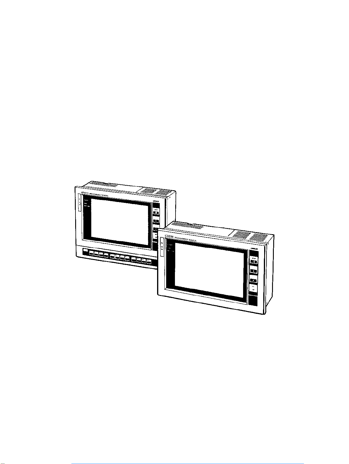
NT600M
Programmable Terminal
Operation Manual
Revised October 1997
OMRON Product References
All OMRON products are capitalized in this manual. The word “Unit” is also capitalized when it refers
to an OMRON product, regardless of whether or not it appears in the proper name of the product.
Artisan Technology Group - Quality Instrumentation ... Guaranteed | (888) 88-SOURCE | www.artisantg.com
Page 4

The abbreviation “Ch,” which appears in some displays and on some OMRON products, often means
“word” and is abbreviated “Wd” in documentation in this sense.
The abbreviation “PC” means Programmable Controller and is not used as an abbreviation for anything else.
IBM and IBM PC/AT are registered trademarks of International Business Machines Corporation.
MS-DOS is a registered trademark of Microsoft Corporation.
Visual Aids
The following headings appear in the left column of the manual to help you locate different types of
information.
Note Indicates information of particular interest for efficient and convenient operation
of the product.
1, 2, 3...
1. Indicates lists of one sort or another, such as procedures, checklists, etc.
OMRON, 1991
All rights reserved. No part of this publication may be reproduced, stored in a retrieval system, or transmitted, in any
form, or by any means, mechanical, electronic, photocopying, recording, or otherwise, without the prior written permission of OMRON.
No patent liability is assumed with respect to the use of the information contained herein. Moreover, because OMRON is
constantly striving to improve its high-quality products, the information contained in this manual is subject to change
without notice. Every precaution has been taken in the preparation of this manual. Nevertheless, OMRON assumes no
responsibility for errors or omissions. Neither is any liability assumed for damages resulting from the use of the information contained in this publication.
ii
Artisan Technology Group - Quality Instrumentation ... Guaranteed | (888) 88-SOURCE | www.artisantg.com
Page 5

About this Manual:
This manual describes the installation and operation of the NT600M Programmable Terminals (PTs) and
includes the sections described below. Further information is provided in manuals on the Host Interface
Units and Support Tool. Refer to the list in
Please read this manual completely and be sure you understand the information provide before attempting to install and operate a Programmable Terminal.
Section 1 Introduction
.
Section 1
of system configurations for programming and operation.
Section 2
switch settings and installation.
Section 3
Section 4
Included is automatic transfer of data from the host computer via character string and numeral tables.
Section 5
the numeral table.
Section 6
Section 7
Section 8
Appendices of OMRON products used with PTs, PT specifications, and a memory check table are
provided at the back of the manual.
introduces the PTs, describes the terminology used in this manual, and provides examples
provides procedures and specifications required to set up a PT system, including hardware
provides steps required for initial PT operation.
describes functions used to create screens and control display attributes on the PT.
describes functions used to input data on-screen and transfer it to the host computer via
describes basic data transfer and maintenance functions.
describes transferring screens online to and from the host computer.
provides troubleshooting and basic maintenance methods, including battery replacement.
!
WARNING Failure to read and understand the information provided in this manual may result in
personal injury or death, damage to the product, or product failure. Please read each
section in its entirety and be sure you understand the information provided in the section
and related sections before attempting any of the procedures or operations given.
Artisan Technology Group - Quality Instrumentation ... Guaranteed | (888) 88-SOURCE | www.artisantg.com
iii
Page 6

TABLE OF CONTENTS
PRECAUTIONS ix . . . . . . . . . . . . . . . . . . . . . . . . . . . . . . . . . . . . . . . . . . . . . . . .
1 Intended Audience x . . . . . . . . . . . . . . . . . . . . . . . . . . . . . . . . . . . . . . . . . . . . . . . .
2 General Precautions x . . . . . . . . . . . . . . . . . . . . . . . . . . . . . . . . . . . . . . . . . . . . . . .
3 Safety Precautions x . . . . . . . . . . . . . . . . . . . . . . . . . . . . . . . . . . . . . . . . . . . . . . . .
SECTION 1 – Introduction 1 . . . . . . . . . . . . . . . . . . . . . . . . . . . . . . . . . . . . . . .
1-1 Introduction 2 . . . . . . . . . . . . . . . . . . . . . . . . . . . . . . . . . . . . . . . . . . . . . . . . . . . . . .
1-2 Features 4 . . . . . . . . . . . . . . . . . . . . . . . . . . . . . . . . . . . . . . . . . . . . . . . . . . . . . . . . .
1-3 Terminology and NT-series Manuals 5 . . . . . . . . . . . . . . . . . . . . . . . . . . . . . . . . . .
1-4 Models 6 . . . . . . . . . . . . . . . . . . . . . . . . . . . . . . . . . . . . . . . . . . . . . . . . . . . . . . . . . .
1-4-1 NT600M Programmable Terminals 6 . . . . . . . . . . . . . . . . . . . . . . . . . . .
1-4-2 Screen Data Memory Boards 6 . . . . . . . . . . . . . . . . . . . . . . . . . . . . . . . .
1-4-3 System ROM 7 . . . . . . . . . . . . . . . . . . . . . . . . . . . . . . . . . . . . . . . . . . . .
1-4-4 Host Interface Units 8 . . . . . . . . . . . . . . . . . . . . . . . . . . . . . . . . . . . . . . .
1-4-5 12-key Function Key Units (for DN-type) 9 . . . . . . . . . . . . . . . . . . . . .
1-5 Support Tools 9 . . . . . . . . . . . . . . . . . . . . . . . . . . . . . . . . . . . . . . . . . . . . . . . . . . . .
1-6 System Configuration 10 . . . . . . . . . . . . . . . . . . . . . . . . . . . . . . . . . . . . . . . . . . . . . .
1-7 Nomenclature and Functions 13 . . . . . . . . . . . . . . . . . . . . . . . . . . . . . . . . . . . . . . . .
1-7-1 Front Panel 13 . . . . . . . . . . . . . . . . . . . . . . . . . . . . . . . . . . . . . . . . . . . . . .
1-7-2 Rear Panel 14 . . . . . . . . . . . . . . . . . . . . . . . . . . . . . . . . . . . . . . . . . . . . . .
SECTION 2 – Switch Settings, Installation, and Wiring 15 . . . . . . . . . . . . . . .
2-1 Switch Settings 16 . . . . . . . . . . . . . . . . . . . . . . . . . . . . . . . . . . . . . . . . . . . . . . . . . . .
2-1-1 System DIP Switch Settings (SW1) 16 . . . . . . . . . . . . . . . . . . . . . . . . . .
2-1-2 Mounting System ROM 17 . . . . . . . . . . . . . . . . . . . . . . . . . . . . . . . . . . . .
2-1-3 Screen Data Memory Board Settings and Installation 18 . . . . . . . . . . . .
2-2 Installation Environment 20 . . . . . . . . . . . . . . . . . . . . . . . . . . . . . . . . . . . . . . . . . . .
2-2-1 Installation Site 20 . . . . . . . . . . . . . . . . . . . . . . . . . . . . . . . . . . . . . . . . . .
2-2-2 Mounting Position 21 . . . . . . . . . . . . . . . . . . . . . . . . . . . . . . . . . . . . . . . .
2-3 Dimensions 22 . . . . . . . . . . . . . . . . . . . . . . . . . . . . . . . . . . . . . . . . . . . . . . . . . . . . . .
2-3-1 Terminals with Function Keys (DF-type) 22 . . . . . . . . . . . . . . . . . . . . . .
2-3-2 PTs With (DT-type) and Without (DN-type) Touch Panels 23 . . . . . . . . .
2-4 Installing the NT600M PT in a Panel 23 . . . . . . . . . . . . . . . . . . . . . . . . . . . . . . . . . .
2-5 Wiring and Connectors 25 . . . . . . . . . . . . . . . . . . . . . . . . . . . . . . . . . . . . . . . . . . . . .
2-5-1 Terminal Block 25 . . . . . . . . . . . . . . . . . . . . . . . . . . . . . . . . . . . . . . . . . .
2-5-2 AC INPUT Terminals 25 . . . . . . . . . . . . . . . . . . . . . . . . . . . . . . . . . . . . .
2-5-3 LG and GR Terminals 26 . . . . . . . . . . . . . . . . . . . . . . . . . . . . . . . . . . . . .
2-5-4 HOST RUN INPUT Terminals 26 . . . . . . . . . . . . . . . . . . . . . . . . . . . . . .
2-5-5 ALM OUTPUT Terminals 27 . . . . . . . . . . . . . . . . . . . . . . . . . . . . . . . . . .
2-6 RS-232C Interface Connector 27 . . . . . . . . . . . . . . . . . . . . . . . . . . . . . . . . . . . . . . .
2-7 12-key Function Key Units (for DN-type PTs) 28 . . . . . . . . . . . . . . . . . . . . . . . . . .
2-8 Mounting Function Key Units (to DN-type PTs) 28 . . . . . . . . . . . . . . . . . . . . . . . . .
SECTION 3 – Initial Operation 31 . . . . . . . . . . . . . . . . . . . . . . . . . . . . . . . . . . .
3-1 Powering Up 32 . . . . . . . . . . . . . . . . . . . . . . . . . . . . . . . . . . . . . . . . . . . . . . . . . . . . .
3-2 Initialization 32 . . . . . . . . . . . . . . . . . . . . . . . . . . . . . . . . . . . . . . . . . . . . . . . . . . . . .
3-2-1 Initializing Memory 32 . . . . . . . . . . . . . . . . . . . . . . . . . . . . . . . . . . . . . . .
3-2-2 Menus 34 . . . . . . . . . . . . . . . . . . . . . . . . . . . . . . . . . . . . . . . . . . . . . . . . . .
3-3 Transferring Data to and from the Support Tool 35 . . . . . . . . . . . . . . . . . . . . . . . . .
3-4 Trial Operation 37 . . . . . . . . . . . . . . . . . . . . . . . . . . . . . . . . . . . . . . . . . . . . . . . . . . .
Artisan Technology Group - Quality Instrumentation ... Guaranteed | (888) 88-SOURCE | www.artisantg.com
v
Page 7

Table of contents
SECTION 4 – Display Functions 39 . . . . . . . . . . . . . . . . . . . . . . . . . . . . . . . . . .
4-1 Character Displays 40 . . . . . . . . . . . . . . . . . . . . . . . . . . . . . . . . . . . . . . . . . . . . . . . .
4-1-1 Types of Characters 40 . . . . . . . . . . . . . . . . . . . . . . . . . . . . . . . . . . . . . . .
4-1-2 Designating Display Positions 40 . . . . . . . . . . . . . . . . . . . . . . . . . . . . . . .
4-1-3 Character Scale 40 . . . . . . . . . . . . . . . . . . . . . . . . . . . . . . . . . . . . . . . . . .
4-1-4 Display Attributes 41 . . . . . . . . . . . . . . . . . . . . . . . . . . . . . . . . . . . . . . . .
4-2 Display Graphics 41 . . . . . . . . . . . . . . . . . . . . . . . . . . . . . . . . . . . . . . . . . . . . . . . . . .
4-3 Normal Screen Changes 42 . . . . . . . . . . . . . . . . . . . . . . . . . . . . . . . . . . . . . . . . . . . .
4-3-1 Procedure for Changing Screens 42 . . . . . . . . . . . . . . . . . . . . . . . . . . . . .
4-4 Continuous Screens 42 . . . . . . . . . . . . . . . . . . . . . . . . . . . . . . . . . . . . . . . . . . . . . . . .
4-5 Overlapping Screens 43 . . . . . . . . . . . . . . . . . . . . . . . . . . . . . . . . . . . . . . . . . . . . . . .
4-6 Numeric Displays 45 . . . . . . . . . . . . . . . . . . . . . . . . . . . . . . . . . . . . . . . . . . . . . . . . .
4-7 Character Strings 46 . . . . . . . . . . . . . . . . . . . . . . . . . . . . . . . . . . . . . . . . . . . . . . . . .
4-8 Bar Graphs 47 . . . . . . . . . . . . . . . . . . . . . . . . . . . . . . . . . . . . . . . . . . . . . . . . . . . . . .
4-9 Lamps 47 . . . . . . . . . . . . . . . . . . . . . . . . . . . . . . . . . . . . . . . . . . . . . . . . . . . . . . . . . .
4-10 Graphics Display 48 . . . . . . . . . . . . . . . . . . . . . . . . . . . . . . . . . . . . . . . . . . . . . . . . . .
4-11 Special Controls 48 . . . . . . . . . . . . . . . . . . . . . . . . . . . . . . . . . . . . . . . . . . . . . . . . . .
4-11-1 Backlight ON/OFF 48 . . . . . . . . . . . . . . . . . . . . . . . . . . . . . . . . . . . . . . . .
4-11-2 Alarm Output On/Off 49 . . . . . . . . . . . . . . . . . . . . . . . . . . . . . . . . . . . . . .
4-11-3 Buzzer On/Off 49 . . . . . . . . . . . . . . . . . . . . . . . . . . . . . . . . . . . . . . . . . . .
4-11-4 Initialize Display History 49 . . . . . . . . . . . . . . . . . . . . . . . . . . . . . . . . . . .
4-11-5 HOST RUN INPUT 49 . . . . . . . . . . . . . . . . . . . . . . . . . . . . . . . . . . . . . . .
4-11-6 Normal/Inverse Display (LCD-type Only) 50 . . . . . . . . . . . . . . . . . . . . .
4-12 Terminal Function 50 . . . . . . . . . . . . . . . . . . . . . . . . . . . . . . . . . . . . . . . . . . . . . . . . .
4-13 Display Speed 50 . . . . . . . . . . . . . . . . . . . . . . . . . . . . . . . . . . . . . . . . . . . . . . . . . . . .
SECTION 5 – Input Functions 53 . . . . . . . . . . . . . . . . . . . . . . . . . . . . . . . . . . . .
5-1 On-screen Switch Inputs 54 . . . . . . . . . . . . . . . . . . . . . . . . . . . . . . . . . . . . . . . . . . . .
5-1-1 Transmitting to the Host 54 . . . . . . . . . . . . . . . . . . . . . . . . . . . . . . . . . . .
5-1-2 Creating Touch Switches (DT-type PTs Only) 55 . . . . . . . . . . . . . . . . . .
5-1-3 Function Keys (NT600M-DF122) 56 . . . . . . . . . . . . . . . . . . . . . . . . . . . .
5-2 Inputting Numeric Settings 56 . . . . . . . . . . . . . . . . . . . . . . . . . . . . . . . . . . . . . . . . . .
5-3 Standalone Function 59 . . . . . . . . . . . . . . . . . . . . . . . . . . . . . . . . . . . . . . . . . . . . . . .
SECTION 6 – System Menu 61 . . . . . . . . . . . . . . . . . . . . . . . . . . . . . . . . . . . . . .
6-1 Configuration of System Menu 62 . . . . . . . . . . . . . . . . . . . . . . . . . . . . . . . . . . . . . .
6-2 System Menu and Transmit Mode 63 . . . . . . . . . . . . . . . . . . . . . . . . . . . . . . . . . . . .
6-2-1 Quit 63 . . . . . . . . . . . . . . . . . . . . . . . . . . . . . . . . . . . . . . . . . . . . . . . . . . .
6-2-2 Transmit Mode 63 . . . . . . . . . . . . . . . . . . . . . . . . . . . . . . . . . . . . . . . . . . .
6-2-3 Maintenance Mode 63 . . . . . . . . . . . . . . . . . . . . . . . . . . . . . . . . . . . . . . .
6-2-4 Expansion Mode 63 . . . . . . . . . . . . . . . . . . . . . . . . . . . . . . . . . . . . . . . . .
6-2-5 Display History 63 . . . . . . . . . . . . . . . . . . . . . . . . . . . . . . . . . . . . . . . . . .
6-2-6 I/O Checks 65 . . . . . . . . . . . . . . . . . . . . . . . . . . . . . . . . . . . . . . . . . . . . . .
6-2-7 PT Settings Check 69 . . . . . . . . . . . . . . . . . . . . . . . . . . . . . . . . . . . . . . . .
6-2-8 Initialization 70 . . . . . . . . . . . . . . . . . . . . . . . . . . . . . . . . . . . . . . . . . . . . .
6-3 Memory Switch Settings 71 . . . . . . . . . . . . . . . . . . . . . . . . . . . . . . . . . . . . . . . . . . . .
SECTION 7 – Online Transfer 75 . . . . . . . . . . . . . . . . . . . . . . . . . . . . . . . . . . . .
7-1 Host to PT 76 . . . . . . . . . . . . . . . . . . . . . . . . . . . . . . . . . . . . . . . . . . . . . . . . . . . . . . .
7-2 PT to Host 76 . . . . . . . . . . . . . . . . . . . . . . . . . . . . . . . . . . . . . . . . . . . . . . . . . . . . . . .
vi
Artisan Technology Group - Quality Instrumentation ... Guaranteed | (888) 88-SOURCE | www.artisantg.com
Page 8

Table of contents
SECTION 8 – Maintenance and Inspection 79 . . . . . . . . . . . . . . . . . . . . . . . . .
8-1 Checking Operation 80 . . . . . . . . . . . . . . . . . . . . . . . . . . . . . . . . . . . . . . . . . . . . . . .
8-2 Changing the Lithium Backup Battery 80 . . . . . . . . . . . . . . . . . . . . . . . . . . . . . . . . .
8-3 Maintenance and Inspection 81 . . . . . . . . . . . . . . . . . . . . . . . . . . . . . . . . . . . . . . . . .
8-3-1 Spare Terminals 81 . . . . . . . . . . . . . . . . . . . . . . . . . . . . . . . . . . . . . . . . . .
8-3-2 Inspection 81 . . . . . . . . . . . . . . . . . . . . . . . . . . . . . . . . . . . . . . . . . . . . . . .
8-3-3 Precautions When Cleaning the PT Screen 82 . . . . . . . . . . . . . . . . . . . . .
8-4 RUN Mode Function Configuration 83 . . . . . . . . . . . . . . . . . . . . . . . . . . . . . . . . . . .
Appendix 85 . . . . . . . . . . . . . . . . . . . . . . . . . . . . . . . . . . . . . . . . . . . . . . . . . . . . . .
A – Standard Models 85 . . . . . . . . . . . . . . . . . . . . . . . . . . . . . . . . . . . . . . . . . . . . . . . . . . . .
B – Specifications 87 . . . . . . . . . . . . . . . . . . . . . . . . . . . . . . . . . . . . . . . . . . . . . . . . . . . . . .
C – Memory Check Table 91 . . . . . . . . . . . . . . . . . . . . . . . . . . . . . . . . . . . . . . . . . . . . . . . .
D – Special Characters 93 . . . . . . . . . . . . . . . . . . . . . . . . . . . . . . . . . . . . . . . . . . . . . . . . . . .
Index 95 . . . . . . . . . . . . . . . . . . . . . . . . . . . . . . . . . . . . . . . . . . . . . . . . . . . . . . . . .
Artisan Technology Group - Quality Instrumentation ... Guaranteed | (888) 88-SOURCE | www.artisantg.com
vii
Page 9

PRECAUTIONS
This section provides general precautions for using the Programmable Terminal.
The information contained in this section is important for the safe and reliable application of the Programmable Terminal. You must read this section and understand the information contained befor e attempting to set up or operate a
Programmable Terminal.
1 Intended Audience x . . . . . . . . . . . . . . . . . . . . . . . . . . . . . . . . . . . . . . . . . . . . . . . . .
2 General Precautions x . . . . . . . . . . . . . . . . . . . . . . . . . . . . . . . . . . . . . . . . . . . . . . . .
3 Safety Precautions x . . . . . . . . . . . . . . . . . . . . . . . . . . . . . . . . . . . . . . . . . . . . . . . . .
Artisan Technology Group - Quality Instrumentation ... Guaranteed | (888) 88-SOURCE | www.artisantg.com
ix
Page 10

Safety Precautions
1 Intended Audience
This manual is intended for the following personnel, who must also have knowledge of electrical systems (an electrical engineer or the equivalent).
• Personnel in charge of installing FA systems.
• Personnel in charge of designing FA systems.
• Personnel in charge of managing FA systems and facilities.
2 General Precautions
The user must operate the product according to the performance specifications
described in the operation manuals.
Before using the product under conditions which are not described in the manual
or applying the product to nuclear control systems, railroad systems, aviation
systems, vehicles, combustion systems, medical equipment, amusement
machines, safety equipment, and other systems, machines, and equipment that
may have a serious influence on lives and property if used improperly, consult
your OMRON representative.
Make sure that the ratings and performance characteristics of the product are
sufficient for the systems, machines, and equipment, and be sure to provide the
systems, machines, and equipment with double safety mechanisms.
This manual provides information for using the Programmable Terminal. Be sure
to read this manual before attempting to use the software and keep this manual
close at hand for reference during operation.
3
WARNING It is extremely important that Programmable Terminals and related devices be
!
used for the specified purpose and under the specified conditions, especially in
applications that can directly or indirectly affect human life. You must consult
with your OMRON representative before applying Programmable Terminals to
the abovementioned applications.
WARNING Do not use input functions such as PT touch switches for applications where
!
danger to human life or serious damage is possible, or for emergency switch
applications.
3 Safety Precautions
Read these safety precautions carefully and make sure you understand them
before using the Programmable Terminal so that you can use it safely and correctly.
Safety Conventions and
their Meanings
DANGER Indicates information that, if not heeded, is likely to result in loss of life or serious
!
This operation manual uses the following conventions and symbols to indicate
cautions, warnings, and dangers in order to ensure safe use of the PT. The cautions, warnings, and dangers shown here contain important information related
to safety. The instructions in these cautions, warnings, and dangers must be
observed.
The conventions used and their meanings are presented below.
injury.
WARNING Indicates information that, if not heeded, could possibly result in loss of life or
!
serious injury.
Caution Indicates information that, if not heeded, could result in relatively serious or mi-
!
nor injury, damage to the product, or faulty operation.
x
Artisan Technology Group - Quality Instrumentation ... Guaranteed | (888) 88-SOURCE | www.artisantg.com
Page 11

Safety Precautions
Caution
!
3
• The ROM may be destroyed if it is mounted while power is being supplied to
the PT.
• Screen memory must be initialized before using a new PT. If the PT is used as
shipped from the factory without initialization, messages indicating errors in
the host will not be displayed.
• After the transfer has been completed, be sure to return to RUN Mode by
pressing the Buzzer Key, Up Key, and Down Key simultaneously. If the power
is turned off or if a reset is executed without having first returned to RUN Mode,
the data that has been transmitted will be corrupted. If that occurs, a message
will be displayed on the screen to indicate that the data has been corrupted.
• If a load (e.g., a buzzer or alarm light) is connected to a 10/02 Terminal or a
32/16 Terminal, it will actually operate. This can be potentially dangerous, so
exercise caution.
• The lithium battery can explode if placed into a fire, or it can explode, burn, or
leak if the + and – terminals are short-circuited or if the battery is recharged or
dismantled. Handle the battery with care.
Artisan Technology Group - Quality Instrumentation ... Guaranteed | (888) 88-SOURCE | www.artisantg.com
xi
Page 12

SECTION 1
Introduction
This section provides information necessary to familiarize you with the features and parts of a PT system.
1-1 Introduction 2 . . . . . . . . . . . . . . . . . . . . . . . . . . . . . . . . . . . . . . . . . . . . . . . . . . . . . .
1-2 Features 4 . . . . . . . . . . . . . . . . . . . . . . . . . . . . . . . . . . . . . . . . . . . . . . . . . . . . . . . . .
1-3 Terminology and NT-series Manuals 5 . . . . . . . . . . . . . . . . . . . . . . . . . . . . . . . . . . .
1-4 Models 6 . . . . . . . . . . . . . . . . . . . . . . . . . . . . . . . . . . . . . . . . . . . . . . . . . . . . . . . . . .
1-4-1 NT600M Programmable Terminals 6 . . . . . . . . . . . . . . . . . . . . . . . . . . . .
1-4-2 Screen Data Memory Boards 6 . . . . . . . . . . . . . . . . . . . . . . . . . . . . . . . .
1-4-3 System ROM 7 . . . . . . . . . . . . . . . . . . . . . . . . . . . . . . . . . . . . . . . . . . . . .
1-4-4 Host Interface Units 8 . . . . . . . . . . . . . . . . . . . . . . . . . . . . . . . . . . . . . . . .
1-4-5 12-key Function Key Units (for DN-type) 9 . . . . . . . . . . . . . . . . . . . . . .
1-5 Support Tools 9 . . . . . . . . . . . . . . . . . . . . . . . . . . . . . . . . . . . . . . . . . . . . . . . . . . . . .
1-6 System Configuration 10 . . . . . . . . . . . . . . . . . . . . . . . . . . . . . . . . . . . . . . . . . . . . . . .
1-7 Nomenclature and Functions 13 . . . . . . . . . . . . . . . . . . . . . . . . . . . . . . . . . . . . . . . . .
1-7-1 Front Panel 13 . . . . . . . . . . . . . . . . . . . . . . . . . . . . . . . . . . . . . . . . . . . . . .
1-7-2 Rear Panel 14 . . . . . . . . . . . . . . . . . . . . . . . . . . . . . . . . . . . . . . . . . . . . . . .
Artisan Technology Group - Quality Instrumentation ... Guaranteed | (888) 88-SOURCE | www.artisantg.com
1
Page 13
Introduction Section 1-1
1-1 Introduction
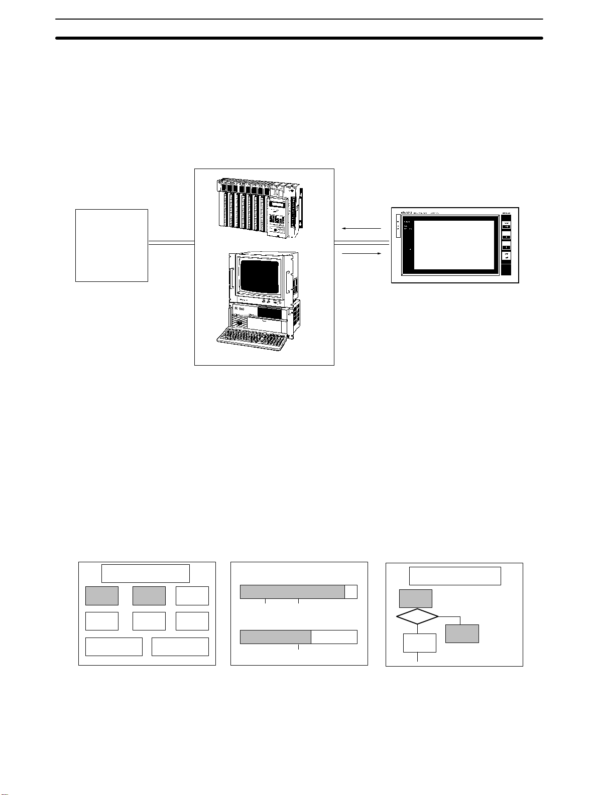
This manual describes the installation and operation of NT600M Programmable Terminals (PTs). Programmable Terminals have three main functions:
1) monitoring operating conditions, 2) directing on-site personnel, and 3) inputting data.
Host
Directing
operations,
monitoring
conditions
Device
Instructions
Programmable Terminal
(Programmable Controller or FA computer)
1) PTs can monitor, in real time, system and equipment operating conditions,
production quantities, and so on. The PT display can show, for example,
whether the production line is operating normally, and what percentage of the
production target has been met. Bar graphs can be continually updated as
data is received from the host. On-screen characters can be displayed as
plain, reverse video, blinking, or reverse blinking. In addition, lamps, bar
graphs, and figures can all be created. Screen data can be registered at the
PT in advance, and can be displayed simply by transmitting the appropriate
screen number from the host.
Lamp Display Bar Graph Display
Operating conditions
Run Air
Run Normal Oil
Emergency
stop
Normal
Error
Rotation (rpm)
0
Oil pressure (kg/cm
0
5.0 10
Graphics Display
Conveyance System
L1-0
36001800
2
)
M10
L1-2
L2-0
2) PTs can inform on-site personnel of current conditions that need to be addressed. Depending on the nature of the situation, built-in or external buzzers
can be sounded to alert personnel to problems that have developed. Depending on factors such as distance from the host, the number of devices
2
Artisan Technology Group - Quality Instrumentation ... Guaranteed | (888) 88-SOURCE | www.artisantg.com
Page 14
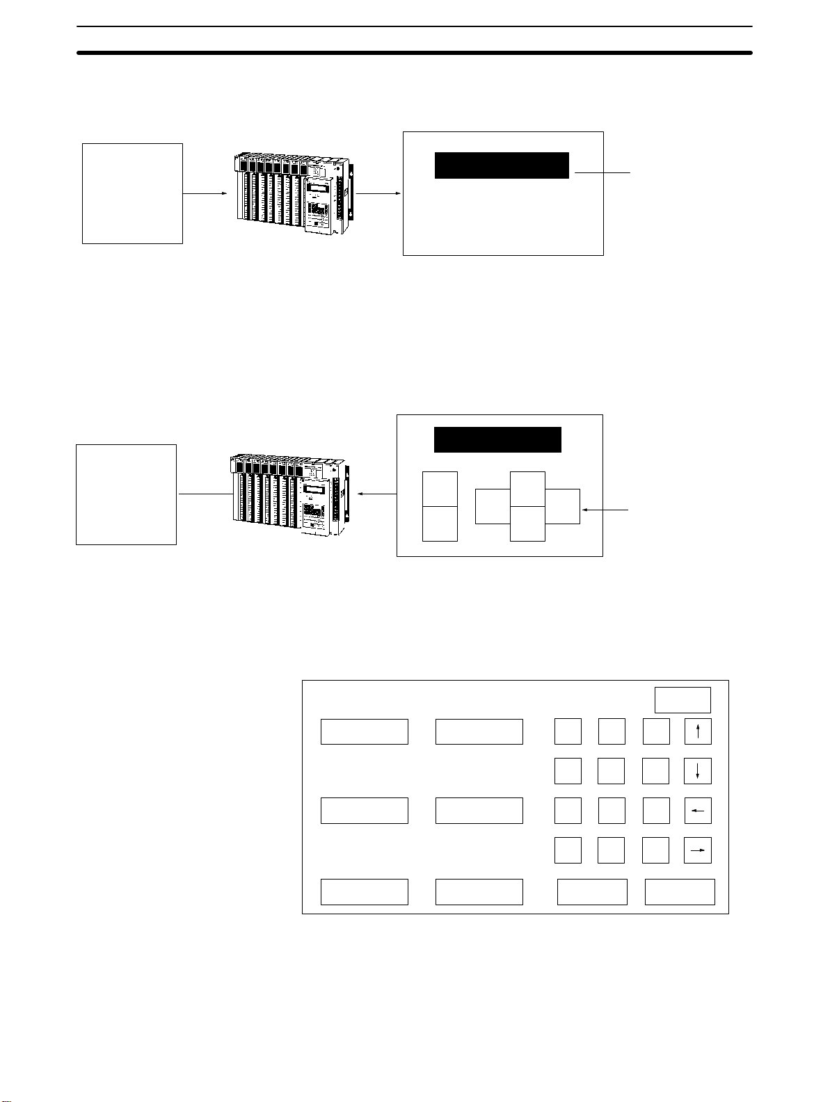
Introduction Section 1-1
connected, and the response time, any of a variety of communications methods may be selected.
Abnormality
occurs!
Device
Normal
operation
Device
EMERGENCY STOP
Air pressure is abnormal.
Please check
PC
PT
(Flashing display)
3) PTs can input data for controlling certain operations and communicating
information to the host. Setting switches and a ten-key pad allows a PT to be
used as a control panel. In the example shown below, touch switches used
for inputs to the host are displayed. When this screen is displayed, the onsite operator can control a device by means of touch switches.
Crane Operation
Run
Left
Stop
PC
PT
Up
Down
Right
(Touch switches
created by Support
Tool.)
Aside from touch switches, the PT can provide inputs by means of numeric
settings and externally connected switches. The illustration below shows a
numeric setting screen that can be used for inputting numeric data.
Tank A
0654 0650
Tank C
0000 0550
Tank E
0800 0990
Tank B
Tank D
Tank F
1 2 3
4 5 6
7 8 9
HO
0
ME
Change Set
MENU
C
The screens used for these operations can be created in advance by using
the “Support Tool” software on a personal computer. The screen data that is
created using the Support Tool can be printed out, saved to a diskette, or
transferred to the PT. An FA Computer, a Programmable Controller, or a
compatible device can be used as the host.
Artisan Technology Group - Quality Instrumentation ... Guaranteed | (888) 88-SOURCE | www.artisantg.com
3
Page 15

2
(V
)
Features Section 1-2
1-2 Features
Wide Selection of Models
Drip-proof Structure
Clear Display
Two-way Communications
with Host
Display Functions
Input Options
The NT600-series PTs provide a choice of three models depending on the
input specifications of your system. You can also choose either of two types
of display devices. Any of six methods can be selected for communicating
with the host, which may be an FA Computer, a Programmable Controller, or
a compatible device.
The PTs have a drip-proof front panel structure when the dust cover is
mounted to protect the display area and the key input area.
Either of two types of display can be selected: an STN liquid crystal display
with a backlight, or a yellow-orange EL (electro-luminescent) display.
Screens at the PT can be changed, messages can be received, and numbers can be displayed from the host. The PT, in turn, can transmit key inputs
and numbers back to the host.
A maximum of 1000 screens can be registered. As many as 64 rectangular
or circular lamps can be created for a single screen, up to a total of 256 and
direct connection can be used without restrictions. Character strings, numerals, bar graphs and simple graphics can also be created and registered.
Depending on the input specifications of the control system, any of three
NT600M types may be selected: the touch panel (DT) type, the non-touchpanel type (DN), and the function key type (DF). DT-type PTs enable the user
to create and use as many as 64 touch switches per screen, up to a total of
256 and direct connection can be used without restrictions. DN-type PTs allow the connection of 12-key Function Key Units, up to a maximum of 32 input points and 16 output points. DF-type PTs enable various inputs by means
of 12 function keys.
Standalone Capability
Screens can be changed on-site, using touch switches, function keys, or external inputs. The screen-changing capability can be allocated to touch
switches or function keys at the time that the screens are created in advance
by the Support Tool.
Online Transfer
Screen data can be written by means of commands from the host when an
RS-232C or RS-422A Host Interface Unit is mounted.
Direct Connection
The direct connection function can be used to directly correlate host data
areas with PT operations. Ordinarily, instructions to the PT and inputs from
the PT are executed in response to commands from the host. Such commands are not required for direct connection, however, and thus the size of
the host program can be greatly reduced. The direct connection can only be
used by DT-type PTs, with the restrictions on Host I/F Units, System ROM,
and Support Tool versions shown in the following table.
PT System ROM Host Interface Unit Support Tool
NT600M-DT12
NT600M-DT211
NT600M-SMR31-E NT600M-LK201 Host Link Interface Unit
NT600M-SMR32-E NT600M-LB122-V1 C200H Host Interface Unit
NT20M-ZASAT-EV4
ersion 4.0 or later
NT-ZA3AT-EV2
When direct connection is used, the PT data is as follows:
Lamps 255 per screen (with no limit on number registered)
Touch switches 128 per screen (with no limit on number registered)
Character string data
memory
50 places per screen (with a maximum of 512
registered)
4
Artisan Technology Group - Quality Instrumentation ... Guaranteed | (888) 88-SOURCE | www.artisantg.com
Page 16
Terminology and NT-series Manuals Section 1-3
1-3 Terminology and NT-series Manuals
Names of items in this manual related to the NT-series Programmable Terminals and SYSMAC C-series Programmable Controllers are defined in the
following tables.
Abbreviations The following abbreviations are used in the text.
Abbreviation Term Meaning
PT Programmable Terminal Refers to an OMRON NT-series Programmable Terminal.
PC Programmable
Controller
I/F interface A communications device that connects the Programmable Terminal with
I/O input/output Refers to PT and PC inputs and outputs.
Refers to an OMRON SYSMAC C-series or CV-series Programmable
Controller, or programmable controllers manufactured by other companies.
peripheral devices.
SYSMAC Terminology
Terminology Explanation
SYSMAC A generic name for OMRON’s Programmable Controllers.
Host Link System A system employing SYSMAC C-series Host Link Units used to create a communications bus
between PCs, between PCs and PTs, etc.
SYSMAC BUS A remote I/O network created between SYSMAC C-series PCs and input/output devices.
C200H An OMRON SYSMAC C-series Programmable Controller.
Reference Manuals The NT20M/NT2000M Series and NT600M Series are covered in the seven
manuals described below.
Name of Manual Contents Manual No.
NT20M/NT2000M Operation
Manual
NT600M Operation Manual This manual provides specifications, functions, and operating
NT-series Host Interface Unit
Operation Manual
NT20M/NT600M Support Tool
Operation Manual
NT-series Host Interface Unit
Direct Connection Operation
Manual
NT-series RS-232C/RS-422A
Interface Unit Operation Manual
NT-series Support Tool Operation
Manual
This manual provides specifications, functions, and operating
instructions for the NT20M and NT2000M Programmable Terminals.
instructions for NT600M Programmable Terminals.
This manual covers the commands, controls, and communications
specifications for operating the NT20M and the NT600M. Refer to
this manual when programming host computer communications.
This manual covers methods for creating screens, including screen
data preparation, switches, lights, and alarms.
(for NT20M-ZASAT-EV4)
This manual covers the Direct Connection feature which has been
added to the Host Interface Unit.
This manual covers the commands, controls, and communications
specifications for operating the NT20M and the NT600M with the
RS-232C/RS-422 Interface Unit. Refer to this manual when
programming host computer communications.
This manual covers methods for creating screens, including screen
data preparation, switches, lights, and alarms. (NT-ZA3AT-EV2)
V001
V002
V003
V004
V015
V016
V028
Artisan Technology Group - Quality Instrumentation ... Guaranteed | (888) 88-SOURCE | www.artisantg.com
5
Page 17
Varies according to
Screen data memor
y
Models Section 1-4
1-4 Models
1-4-1 NT600M Programmable Terminals
There are three types of NT600M PTs, shown in the following table. There
are also two types of display from which to choose.
PT Display device Model number System ROM Screen data mem.
Touch panel (DT)
Without touch panel (DN) EL NT600M-DN211
Function Key Unit (DF) LCD with backlight NT600M-DF122
LCD with backlight NT600M-DT122
EL NT600M-DT211
NT600M-jj122/211
Type of Unit
DT: Touch-panel
DN: Non-touch-panel
DF: Function-key
Purchased separately.
which Host Interface
Unit is installed. or IC sockets for
Purchased separately.
boards can be SRAM
commercially
available EPROM or
EEPROM.
y
1-4-2 Screen Data Memory Boards
A Screen Data Memory Board is required for registering screen, character
string, and numeric data. The Screen Data Memory Board is not built into the
PT and must be purchases separately.
NT600M-Mjjjj
Model Type of memory Memory capacity Remarks
NT600M-MP251
NT600M-MR641
NT600M-MR151
NT600M-MR251
IC socket type
SRAM
SRAM
SRAM
(Depends on memory chip.)
64K
128K
256K
NT600M-series, basic model
Memory capacity
Type of memory
P: IC socket type
R: SRAM-type
Screen Data Memory Board
NT600M-series, basic model
IC-socket for memory chip*
Type and capacity fixed.
Type and capacity fixed.
Type and capacity fixed.
Memory Chips The memory chips that can be installed in the NT600M-MP251 IC socket are
6
Note *The NT600M-MP251 provides only an IC socket and is not equipped with a
memory chip. The memory chip must be installed by the user.
shown in the table below. Use either the model shown here or an equivalent.
Artisan Technology Group - Quality Instrumentation ... Guaranteed | (888) 88-SOURCE | www.artisantg.com
Page 18
Models Section 1-4
If an equivalent is not used, the capacity of the memory backup battery may
not be sufficient.
Memory Capacity and
Number of Screens
Type Memory
capacity
SRAM 32K bytes RAM22-15 HM62256ALP-15 (Hitachi).
128K bytes RAM13-10 HM628128LP-10 (Hitachi).
EPROM 64K bytes ROM-KD-B M5M27C512AK-12 (Mitsubishi)
128K bytes ROM13-12B HN27C101AG-12 (Hitachi).
256K bytes ROM23-15B M5M27C201K-15 (Mitsubishi)
EEPROM 32K bytes EER22-20 HN58C256P-20 (Hitachi).
Model Recommended memory chips
Screen memory capacity varies according to which Screen Data Memory
Board is installed. The screen memory capacity, in turn, determines the number of screens that can be registered. Use the table below as a guide to select the amount of memory suitable for your needs.
Screen memory capacity Number of registered screens
32K bytes Mostly messages: 40 screens
Mostly graphics: 15 screens
64K bytes Mostly messages: 120 screens
Mostly graphics: 40 screens
128K bytes Mostly messages: 250 screens
Mostly graphics: 100 screens
256K bytes Mostly messages: 600 screens
Mostly graphics: 200 screens
Note The table above is strictly a guide. If the messages or other display data per
screen increase, the number of screens that can be registered will decrease.
Likewise, if the messages decrease, the number of screens that can be registered will increase.
1-4-3 System ROM
Purchase the System ROM according to the NT600M and Host Interface Unit
models that are used.
NT600M
Host I/F Unit
NT600M-LK201 (RS-232C) (see note 1)
NT600M-LK202 (RS-422A)
NT600M-LK201 (Host Link) (see note 1)
NT600M-RT201 (SYSMAC BUS)
NT600M-LB122-V1 (C200H) (see note 1) NT600M-SMR02-EV1 --NT600M-LK201 (see note 1) (Host Link) --- NT600M-SMR31-E (Direct connection
NT600M-LB122-V1 (C200H) (see note 2) --- NT600M-SMR32-E (Direct connection
NT600M-SMR01-EV1 ---
NT600M-DT122/211
NT600M-DN122/211
NT600M-DF122
can be used when version 4 of the
Support Tool is used.)
can be used when version 4 of the
Support Tool is used.)
NT600M-DT122
NT600M-DT211
Artisan Technology Group - Quality Instrumentation ... Guaranteed | (888) 88-SOURCE | www.artisantg.com
7
Page 19
ith
Models Section 1-4
Note 1. RS-232C Interface Units and Host Link Interface Units are the same
(NT600M-LK201). Change the communications specifications by means
of the internal DIP switch.
NT600M-SMRjj-EVj
Version
Overseas specifications (English)
Communications
01: RS-232C, RS-422A, SYSMAC WAY,
SYSMAC BUS Interface
02: C200H Host Interface
03: SYSMAC BUS/2, 32/32 Parallel Interface
31: Host Interface Direct Connection
32: C200H Host Interface
System ROM
NT600M-series, basic model
2. For the NT600M-LB122-V1, set the pin 4 of the Interface Unit’s DIP switch
SW2 ON or OFF to determine whether to allow direct connection or not.
Without direct connection: Turn ON pin 4 of SW2
With direct connection: Turn OFF pin 4 of SW2.
1-4-4 Host Interface Units
The Host Interface Unit provides the interface for communications between
the PT and the host (either a Programmable Controller or an FA computer).
The Host Interface Unit models that can be used with the NT600M PT are
shown in the table below. Select the Host Interface Unit to match the communications specifications of the system.
NT600M-jjjjj
Model number
Communications specifications
LK: Serial communications
RT: Remote communications
LB: C200H Host Interface
NT600M-series, basic model
Name Model number Remarks
RS-232C Interface Unit NT600M-LK201
RS-422A Interface Unit NT600M-LK202
SYSMAC BUS Interface Unit NT600M-RT121 Can be connected as a Slave Unit in a SYSMAC Wired Remote
Host Link Interface Unit NT600M-LK201 Can communicate one-to-one with a SYSMAC Host Link Unit.
C200H Host Interface Unit NT600M-LB122-V1 Can be connected to a SYSMAC C200H, C20H, C40H, or C60H
Connect for general-purpose communications with an FA
p
computer or personal computer. For communications w
SYSMAC PC, connect to an ASCII Unit.
I/O System.
PC to provide the functions of an Expansion I/O Rack.
p
p
a
8
Artisan Technology Group - Quality Instrumentation ... Guaranteed | (888) 88-SOURCE | www.artisantg.com
Page 20
Support Tools Section 1-5
1-4-5 12-key Function Key Units (for DN-type)
Function-key input for NT600M non-touch panel (DN) type models is made
possible by attaching an NT600M-FK210 12-key Function Key Unit.
NT600M-DN211 PT
(Without touch panel)
NT600M-FK210
12-key Function Key Unit
1-5 Support Tools
NT600M screen data, memory table data, and system data are all created by
the Support Tool. In order to fully utilize the functions of the NT600M PTs,
use the NT-ZA3AT-EV2 Support Tool or a version of NT20M-ZASAT-EV4 or
higher.
NT20M-ZASAT-EVj
Version
Overseas specifications (English)
Compatible platform
AT: IBM PC/AT compatible
Floppy disk size
3: 3.5 inch
5: 5.25 inch
S: 3.5 and 5 inch
Support software
NT model
NT: NT Series (common)
NT20M: NT20M Series
Contrast Between Functions when New and Old Versions of Peripheral Devices are Used
(1) I/O Functions
Function
Lamps (bit designation)
Display attributes: Lit or
flashing
Touch switches: Reverse
video display during input
(yes or no)
Standalone function F X F X All models X: Cannot be used.
NT20M-ZASAT
Support Tool
-EV4
onwards
F X F X All models X: Only “lit” is available
F X F X DT-type only X: Setting not possible.
-EV1 -EV1 -E
NT600M-SMRjjj
System ROM
PT Models Remarks
for bit designation
control.
Artisan Technology Group - Quality Instrumentation ... Guaranteed | (888) 88-SOURCE | www.artisantg.com
9
Page 21

F
F
System Configuration Section 1-6
(2) Display Functions
Function
Vertical and
horizontal
display
Bar
graphs
Lamp display:
Rectangular or circular
Lamps/touch switches:
Guide character mark
input
Touch switches: Solid or
rectangular frame
Numeric setting 10-key
layout
Numeric display
enlargement (64x max.)
Direct connection See note 3. SMR 31-E/32-E DT-type only
Display width
enlargement (2
to 255 dots)
+/– display
% value
enlargement
display
NT20M-ZASAT
Support Tool
-EV4
onwards
F X F X All models
F X F X All models
F X F X All models X: Equivalent display
-EV1 -EV1 -E
NT600M-SMRjjj
System ROM
PT Models Remarks
X: Horizontal only.
X: Select either 8 or 16
dots.
X: + direction only.
X: Equivalent display
only.
X: Rectangular only.
X: Mark input not
possible.
DT-type only X: Rectangular frame
only.
Only when the screen
(See note 1.)
attribute “10-key” is set to
“User.”
only.
Notes 3. Some restrictions may apply, depending on the PT model.
4. In order to use the direct connection function, a Support Tool version of
“-EV4” or higher must be used.
1-6 System Configuration
In order to operate the NT600M, connect a personal computer or a Programmable Controller, to serve as a host, to the Host Interface Unit (sold separately) at the back of the NT600M. For details on connecting the Host Interface Unit, and on host programs, refer to the
Manual
The following interfaces can be used for communications: RS-232C,
RS-422A, Wired Remote I/O System (SYSMAC BUS), Host Link System
(SYSMAC WAY), or C200H Host Interface. A Screen Data Memory Board,
NT600M-MP/MRjjj, is also required and must be purchased separately.
.
Host Interface Unit Operation
10
Artisan Technology Group - Quality Instrumentation ... Guaranteed | (888) 88-SOURCE | www.artisantg.com
Page 22
System Configuration Section 1-6
RS-232C Interface Using the NT600M-LK201 Host Interface Unit, the Programmable Terminal
can be connected one-to-one to a personal computer or to an ASCII Unit
mounted to a Programmable Controller.
C200H, C500, C1000H,
or C2000H PC
ASCII Unit
NT600M with
NT600M-LK201
RS-232C
15 m max.
Personal computer
NT600M with
NT600M-LK201
RS-232C
15 m max.
RS-422A Interface Using the NT600M-LK202 Host Interface Unit and 3G2A9-AL004-(P) and
3G2A9-AL001 Link Adapters, up to 16 Programmable Terminals can be connected to a to a PC through an ASCII Unit, or to an FA computer.
C-series PC
ASCII Unit
(RS-232C)
Personal computer
3G2A9-AL001
Link Adapters
NT600M with
NT600M-LK202
3G2A9-AL004-(P)E
Link Adapter
RS-422A
Cable length: 500 m max.
Branch lines: 10 m max. each.
Artisan Technology Group - Quality Instrumentation ... Guaranteed | (888) 88-SOURCE | www.artisantg.com
11
Page 23
System Configuration Section 1-6
Host Link Interface Using the NT600M-LK201 Host Interface Unit, the Programmable Terminal
can be connected one-to-one to a Host Link Unit mounted to a Programmable Controller.
Mini H-type, C200H, C500, C1000H, C2000H PC
Host Link Unit
RS-232C
15 m max.
NT600M with
NT600M-LK201
SYSMAC BUS Interface Using NT600M-RT121 Host Interface Units, up to 8 Programmable Terminals
can be connected to a PC through a Wired Remote I/O Master Unit.
8 Terminals max.
C200H, C500, C1000H, or
C2000H PC
NT600M with
NT600M-RT121
Remote I/O
Master Unit
200 m max. (2 wire cable)
C200H Host Interface With an NT600M-LB122-V1 (for direct connection) Interface Unit, the inter-
face is set up simply by connecting one-to-one with C200H-CN221 Connection Cable to a C200H CPU Rack or Expansion I/O Rack. It is also possible
to connect a PT to a C20H, C28H, C40H, or C60H CPU Unit or I/O Units. Be
sure to use a noise filter when connecting CjjH. Refer to the
Units Operation Manual
for details.
Host Interface
12
Be sure to use a noise filter (TDK’s ZGB2202-O1U or equivalent) when connecting to the Mini H-type PC.
1, 2, 3...
1. The noise filter must be inserted into the power line of the Mini H-type
PC.
2. The distance between the noise filter and the Mini H-type PC must be as
short as possible.
3. Keep the noise filter away from high-tension lines.
4. The case of the noise filter must be grounded to the FG terminal of the
Mini H-type PC.
Noise filter
1
IN OUT
2
Artisan Technology Group - Quality Instrumentation ... Guaranteed | (888) 88-SOURCE | www.artisantg.com
4
3
+
24 V24 V
–
Page 24
Nomenclature and Functions Section 1-7
In a C200H PC System, you can ordinarily connect two Expansion I/O Racks to
the CPU Rack. The C200H Host Interface Unit itself, however, functions as an
Expansion I/O Rack, and therefore when using a C200H Host Interface Unit, you
can only connect one other Expansion I/O Rack. (If the CPU Rack is either
C200H-CPU02 or C200H-CPU22, it is not possible to connect both an Expansion Rack and a PT.)
CPU Rack
C20H/28H/40H/60H
CPU Unit
C200H Expansion I/O
Connection Cable
Expansion I/O Rack
NT600M PT + NT600M-LB122-V1
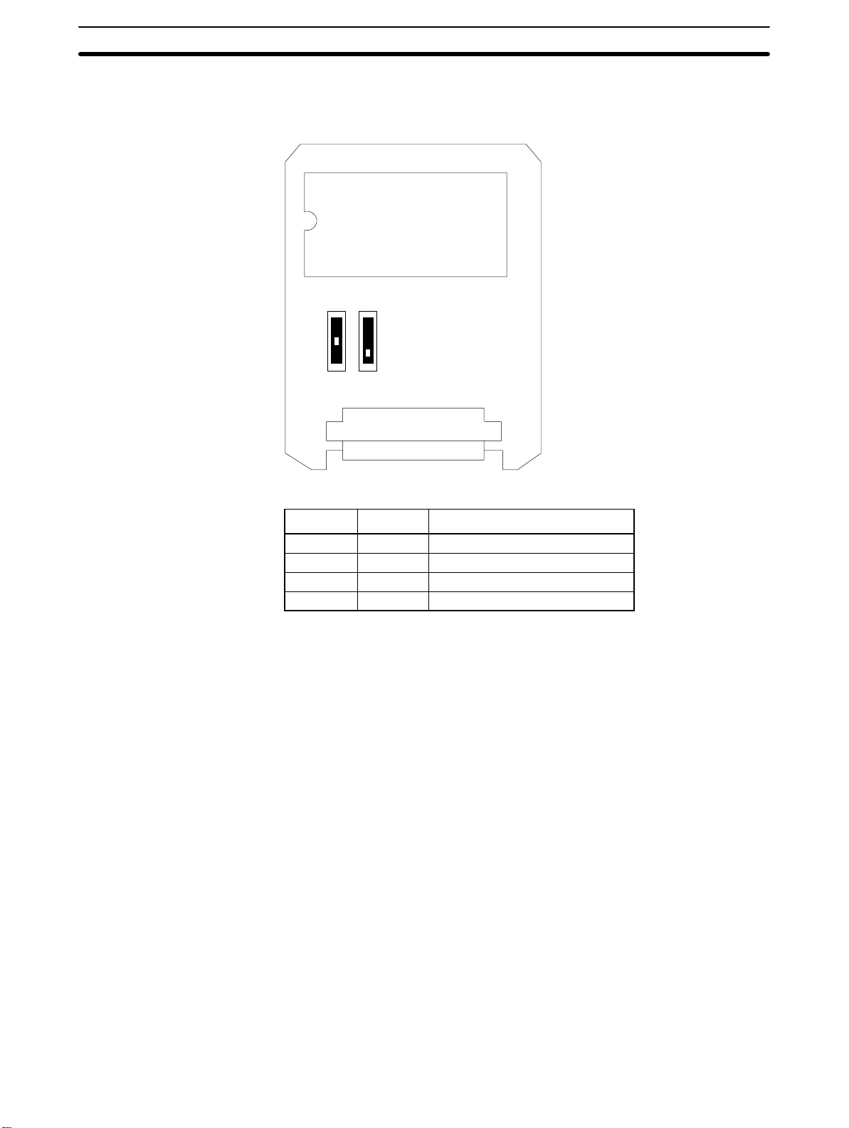
1-7 Nomenclature and Functions
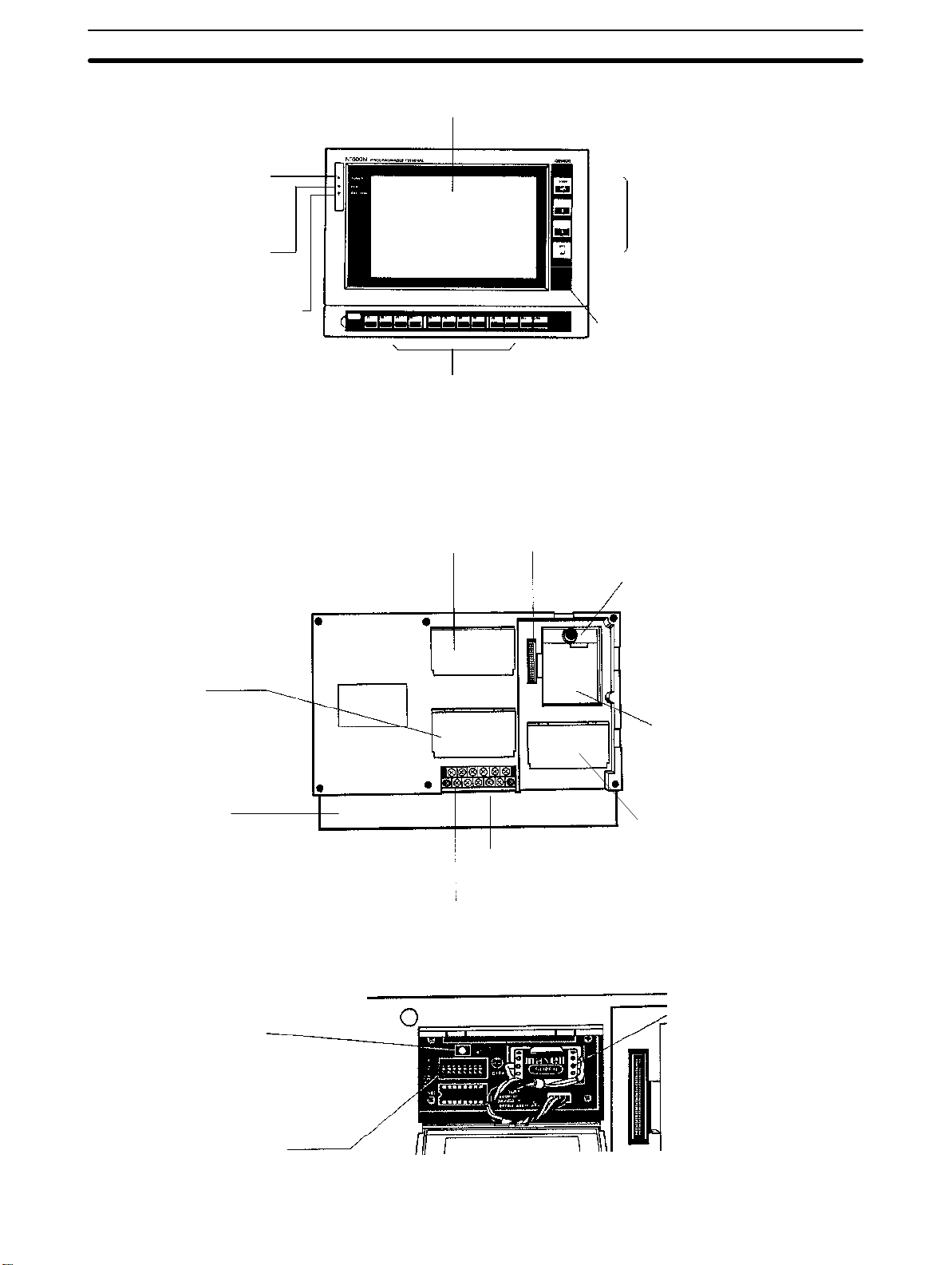
1-7-1 Front Panel
The illustrations below show the front panels of PTs with and without touch
panels (i.e., DT-type and DN-type PTs) and PTs with function keys (i.e., DFtype PTs). A 12-key Function Key Unit can be attached to a DN-type PT to
give it the same outer appearance and functions of a DF-type PT.
CjjH I/O Unit
NT600M PT +
NT600M-LB122-V1
NT600M-DT/DNjjj: Programmable Terminals With and Without a Touch Panel
POWER Indicator (green)
Lit while power is on.
RUN Indicator (green)
Lit during operation
BAT LOW Indicator (red)
Lights if the lithium
battery voltage level
drops.
Display
Touch Switches (touch panel type only)
Used as an input device corresponding to
the display screen.
Artisan Technology Group - Quality Instrumentation ... Guaranteed | (888) 88-SOURCE | www.artisantg.com
System Keys
Used for maintenance of the N600M,
selecting the System Menu, etc. Used
during operation for scrolling the
screen and inputting numeric values.
Dust-proof Cover (liquid crystal type only)
Covers the contrast control. Turning the
contrast control clockwise increases the
contrast.
13
Page 25
Nomenclature and Functions Section 1-7
NT600M-DF122: Programmable Terminals with Function Keys
Display
POWER Indicator (green)
Lit while power is on.
RUN Indicator (green)
Lit during operation
BAT LOW Indicator (red)
Lights if the battery level
drops
Note The operation of the BAT LOW LED will be unstable if a battery is not
installed.
1-7-2 Rear Panel
All Models (NT600M-DT/DN/DFjjj)
Function Keys
Used for input.
Switch cover
System Keys
Used for maintenance of the
NT600M, selecting the System
Menu, etc. Used during operation for scrolling the screen and
inputting numerical values.
Drip-proof Cover (liquid crystal type only)
The contrast control is behind this cover. Turning it clockwise increases the
contrast.
Host Interface Unit connector
This connector is used for connecting
to a Host Interface Unit.
Memory Board fitting
This fitting comes off by pulling up
on the black knob. To put the fitting back on, push down until the
knob snaps into place.
Connector cover
The Support Tool interface connector is located under this cover. This is used when transferring screen data between the
NT600M and Support Tool.
Function Keys
(DF-type only)
Switch Cover Area
Reset switch
Pressing this switch initializes the NT600M.
The status of screen
data before initialization
is retained.
System DIP switch
I/O interface
connector
Terminal block
Memory Board installation space
Insert the Screen Data Memory
Board here.
System ROM cover
Open this cover to access the
System ROM socket.
Lithium battery
14
Artisan Technology Group - Quality Instrumentation ... Guaranteed | (888) 88-SOURCE | www.artisantg.com
Page 26

Switch Settings, Installation, and Wiring
This section provides procedures to set hardware switches and install the PT.
2-1 Switch Settings 16 . . . . . . . . . . . . . . . . . . . . . . . . . . . . . . . . . . . . . . . . . . . . . . . . . . . .
2-1-1 System DIP Switch Settings (SW1) 16 . . . . . . . . . . . . . . . . . . . . . . . . . . .
2-1-2 Mounting System ROM 17 . . . . . . . . . . . . . . . . . . . . . . . . . . . . . . . . . . . .
2-1-3 Screen Data Memory Board Settings and Installation 18 . . . . . . . . . . . . .
2-2 Installation Environment 20 . . . . . . . . . . . . . . . . . . . . . . . . . . . . . . . . . . . . . . . . . . . .
2-2-1 Installation Site 20 . . . . . . . . . . . . . . . . . . . . . . . . . . . . . . . . . . . . . . . . . . .
2-2-2 Mounting Position 21 . . . . . . . . . . . . . . . . . . . . . . . . . . . . . . . . . . . . . . . . .
2-3 Dimensions 22 . . . . . . . . . . . . . . . . . . . . . . . . . . . . . . . . . . . . . . . . . . . . . . . . . . . . . . .
2-3-1 Terminals with Function Keys (DF-type) 22 . . . . . . . . . . . . . . . . . . . . . . .
2-3-2 PTs With (DT-type) and Without (DN-type) Touch Panels 23 . . . . . . . . .
2-4 Installing the NT600M PT in a Panel 23 . . . . . . . . . . . . . . . . . . . . . . . . . . . . . . . . . . .
2-5 Wiring and Connectors 25 . . . . . . . . . . . . . . . . . . . . . . . . . . . . . . . . . . . . . . . . . . . . . .
2-5-1 Terminal Block 25 . . . . . . . . . . . . . . . . . . . . . . . . . . . . . . . . . . . . . . . . . . .
2-5-2 AC INPUT Terminals 25 . . . . . . . . . . . . . . . . . . . . . . . . . . . . . . . . . . . . . .
2-5-3 LG and GR Terminals 26 . . . . . . . . . . . . . . . . . . . . . . . . . . . . . . . . . . . . . .
2-5-4 HOST RUN INPUT Terminals 26 . . . . . . . . . . . . . . . . . . . . . . . . . . . . . . .
2-5-5 ALM OUTPUT Terminals 27 . . . . . . . . . . . . . . . . . . . . . . . . . . . . . . . . . .
2-6 RS-232C Interface Connector 27 . . . . . . . . . . . . . . . . . . . . . . . . . . . . . . . . . . . . . . . .
2-7 12-key Function Key Units (for DN-type PTs) 28 . . . . . . . . . . . . . . . . . . . . . . . . . . .
2-8 Mounting Function Key Units (to DN-type PTs) 28 . . . . . . . . . . . . . . . . . . . . . . . . . .
SECTION 2
Artisan Technology Group - Quality Instrumentation ... Guaranteed | (888) 88-SOURCE | www.artisantg.com
15
Page 27
Switch Settings Section 2-1
2-1 Switch Settings
There are switches to set under the switch cover on the back of the Terminal
and also on the Host Interface Unit. For Host Interface Unit switch settings,
refer to the
Host Interface Unit Operation Manual
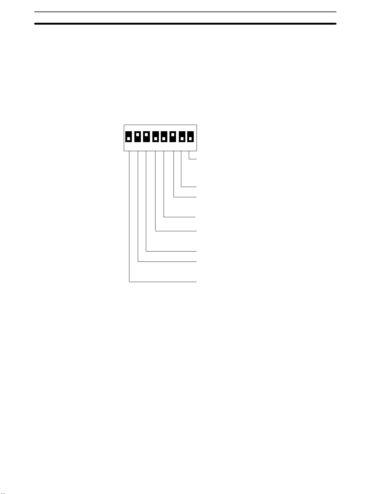
2-1-1 System DIP Switch Settings (SW1)
The 8-position DIP switch for system settings is located under the DIP switch
cover on the back of the Terminal. Be sure that power is off when changing
switch settings.
SW1
ON
12345678
Communications specification
(only for when NT600M-LK201 is mounted)
ON: Host Link
OFF: RS-232C
Not used.
Mode change enable/disable
ON: Enable
OFF: Disable
Not used.
(The settings at the time of shipping
are as shown on the left.)
.
Bit designation for lamps/touch switches
ON: 0 to 63
OFF: 0 to 111
Reserved for system use. (Always keep ON.)
HOST RUN input enable/disable
ON: Disable
OFF: Enable
Automatic reset after communications error
ON: No automatic reset.
OFF: Automatic reset.
16
Artisan Technology Group - Quality Instrumentation ... Guaranteed | (888) 88-SOURCE | www.artisantg.com
Page 28
Switch Settings Section 2-1
Pin no. Setting Content
1 Automatic reset after
communications error.
ON: No automatic reset.
OFF: Automatic reset.
2 Host RUN input enable/disable
ON: Disable
OFF: Enable
3 ON This pin is reserved for system use, and must remain set to ON. If this
4 Bit designation for lamps and
touch switches
5 Not used. --6 Mode change enabled/disable
ON: Enable
OFF: Disable
7 Not used. --8 Communications specification
setting (only when NT600M-LK201
is used)
ON: Host Link Unit
OFF: RS-232C
“Automatic reset” means that, when an error occurs, no error message
will be displayed and the next command will be executed when received.
“No Automatic reset” means that, when an error occurs, an error message will be displayed and operation will stop. If an RS-232C or RS-422A
Interface Unit is mounted, the host will be notified that an error occurred
and there will be no automatic reset regardless of whether this pin is set
to ON or OFF.
If this pin is turned OFF, then the host RUN input will be enabled and PT
operation can be controlled by external sequences. If this pin is set to
ON, the PT will operate but when the host RUN input turns OFF, Host
Error will be displayed and operation will stop.
pin is set to OFF, messages will not display properly.
This pin designates the bits for lamp and touch switch display control for
when Host Link Interface Units or C200H Host Interface Units are used.
“Mode change” refers to changing between the System Menu and Transmit Mode, Maintenance Mode, or RUN Mode. When an RS-232C or
RS-422A Host Interface Unit is used, mode changes can be prohibited
by means of a command from the host.
The NT600M-LK201 can be used as either a Host Link Interface Unit or
an RS-232C Interface Unit. Operation will not be possible if the setting of
this switch does not match the communications system. If another type
of Host Interface Unit is mounted, this setting will be ignored.
2-1-2 Mounting System ROM
Turn off the power supply to the PT and mount the System ROM into the PT
as described below.
1, 2, 3...
1. Open the System ROM cover on the back of the PT.
NT600M-DF122 only
System ROM cover
Artisan Technology Group - Quality Instrumentation ... Guaranteed | (888) 88-SOURCE | www.artisantg.com
17
Page 29
Switch Settings Section 2-1
2. When the System ROM cover is opened, the IC socket will be exposed.
Turn the tightening screw (located to the left of the IC socket) to align
the slot with the O (open).
Label
Tightening
screw
3. Mount the ROM to the socket in the direction indicated on the label and
turn the tightening screw clockwise to the C (close) secure the ROM.
Socket
0
Caution The ROM may be destroyed it mounted while power is being supplied to the PT.
!
0
Insufficiently tightened
Turn off the power supply before mounting the System ROM.
Notes 1. The PT may not operate properly if the IC socket is not completely se-
cured. Be sure to install the System ROM securely.
2. OMRON reserves all copyrights to the programs on the System ROM.
Copying these programs is forbidden.
2-1-3 Screen Data Memory Board Settings and Installation
There are two types of Screen Data Memory Board: SRAM type and IC socket type. The NT600M-MP251 Screen Data Memory Board does not come
with a memory chip installed, and the memory chip must be purchased separately.
The memory type and capacity must be set for the NT600M-MP251.
Switches SW M1 and SW M2 are used to set the type and capacity of the
screen data memory chip installed in the top socket of the Screen Data
18
Artisan Technology Group - Quality Instrumentation ... Guaranteed | (888) 88-SOURCE | www.artisantg.com
Page 30
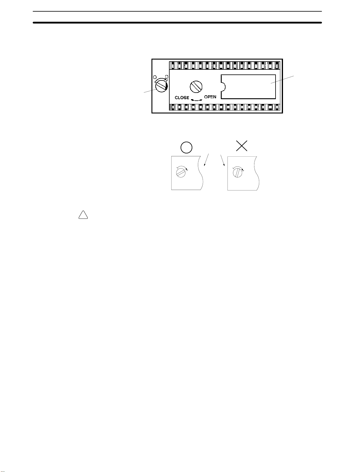
Switch Settings Section 2-1
Memory Board. Set these switches to match the memory chip which is installed.
NT600M-MP251
Socket
The factory-set default setting is shown at the left.
Top
Middle
Bottom
SW M2 SW M1
Connector
Settings
Installation
SW M2 SW M1
Top Bottom 64K, EPROM
Middle Bottom 128K, EPROM
Bottom Bottom 256K, EPROM
Top Middle 32K, EEPROM
Screen data memory
Note 1. Be sure that the power is off when changing the settings. If settings are
made with the power on, memory may be lost or damaged.
2. Carefully check the switch settings and the memory chip before turning
the power on. If the memory is different from that specified on the switch
settings, the PT will not operate correctly.
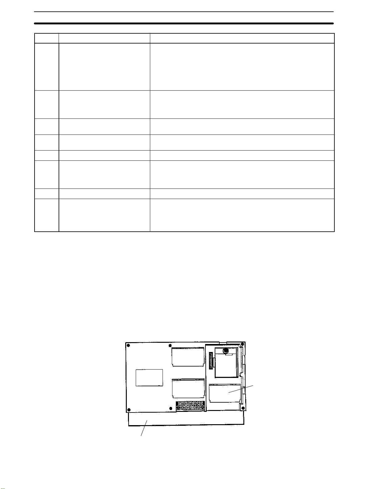
Install the Screen Data Memory Board in the order shown below. If the Host
Interface Unit is mounted, remove it before installation.
1, 2, 3...
1. Turn off the power supply to the PT.
Artisan Technology Group - Quality Instrumentation ... Guaranteed | (888) 88-SOURCE | www.artisantg.com
19
Page 31

Installation Environment Section 2-2
2. Place the Screen Data Memory Board on the main rail, push the spacer
in the direction of the arrow until it makes a clicking sound, and line the
board up with the connector.
Rail
Spacer
Connector
Lined up with connector
3. Holding the Memory Board’s installation fitting as shown in diagram A,
insert the black latch on the bottom into the hole in the main unit and
press the black knob down until it clicks into place.
When the knob is
pulled up, it looks
like Illustration A
on the left.
Installation fitting
Black knob
Black latch
AB
Installation fitting
Spacer
Screen Data Memory Board
When removing the Screen Data Memory Board, first turn off the power to
the PT and then remove the installation fitting by pulling up on the black
knob. Then pull the Memory Board’s spacer in the opposite direction of that
shown above and take out the Memory Board.
2-2 Installation Environment
The NT600M has strong environmental resistance and high reliability, but you
can maximize system reliability and make the most of its functions by observing the following considerations during installation.
2-2-1 Installation Site
Avoid installing the NT600M where any of the following conditions exist.
• Ambient temperatures exceeding a range of 5°C to 40°C for liquid crystal
display PTs or 0°C to 50°C for EL display PTs.
• Abrupt temperature changes and condensation.
20
Artisan Technology Group - Quality Instrumentation ... Guaranteed | (888) 88-SOURCE | www.artisantg.com
Page 32

Installation Environment Section 2-2
• Relative humidity exceeding a range of 35% to 85%.
• Corrosive or inflammable gasses.
• Strong magnetism.
• Excessive dust, salt, or iron dust.
• Direct vibration or shock.
• Direct sunlight.
• Spray from water, oil, or chemicals (the front panel is basically drip-proof).
2-2-2 Mounting Position
Mounting Location PTs with LCD display have a field of vision of 20° up, 30° down, and 30° right
and left. Install the Terminal at a height and direction that make it easy for the
operator to see.
Ambient Temperature The ambient operating temperature range is 5°C to 40°C for liquid crystal
display PTs and 0°C to 50°C for EL display PTs. Take the following factors
into consideration.
• Leave sufficient ventilation space.
• Do not install directly above machinery that puts out a lot of heat (e.g.,
heaters, transformers, high-capacity resistors).
• If the ambient temperature of a PT with LCD display rises above 40%C or
that of a PT with EL display rises above 50%C, set up a fan or air conditioner.
Control panel
Louver
Fan
PT
Operation and Maintenance For safety during operation and maintenance, place the Terminal as far as
possible from high-voltage machinery and power equipment.
Improving Noise Resistance Do not install in a panel with high-voltage devices and install at least 200 mm
from electric power lines. To avoid noise interference from external devices,
separate them with a transformer or noise filter when wiring.
Power line
200 mm min.
PT
200 mm min.
Artisan Technology Group - Quality Instrumentation ... Guaranteed | (888) 88-SOURCE | www.artisantg.com
21
Page 33

Dimensions Section 2-3
• When installing the Terminal near devices with strong electrical or magnetic
fields (such as solenoids), allow a distance of at least 40 mm, more if necessary.
Solenoid
40 mm min.
Solenoid
NT600M
40 mm min.
2-3 Dimensions
All dimensions are in millimeters.
2-3-1 Terminals with Function Keys (DF-type)
The dimensions illustrated below are for PTs with function keys (i.e., DF-type
PTs). PTs without a touch panel (i.e., a DN-type PT) will have the same outer
appearance and dimensions as a DF-type PT.
313
238
186
226
22
325
Artisan Technology Group - Quality Instrumentation ... Guaranteed | (888) 88-SOURCE | www.artisantg.com
12
105
Page 34

Installing the NT600M PT in a Panel Section 2-4
2-3-2 PTs With (DT-type) and Without (DN-type) Touch Panels
313
198
325
2-4 Installing the NT600M PT in a Panel
The NT600M is designed to be inserted in a panel. Install as follows:
1, 2, 3...
1. Cut a hole in the panel in accordance with the recommended dimensions shown below. The panel should be between 1.6 and 4.8 mm thick.
All dimensions are in millimeters.
NT600M-DF122 or NT600M-DNjjj
Installation
space
227 mm
+0.5
–0
186
12
105
+ 12-key Function Key Unit
314 mm+0.5
NT600M-DTjjj/DNjjj
Installation
space
314 mm+0.5
Artisan Technology Group - Quality Instrumentation ... Guaranteed | (888) 88-SOURCE | www.artisantg.com
186.5 mm
+0.5
–0
23
Page 35

Installing the NT600M PT in a Panel Section 2-4
2. Insert the PT into the hole from the front of the panel.
3. Use the accessory metal fittings and tool to fasten the PT to the panel
surface. Do not use a screwdriver. A screwdriver may damage the fittings or the PT.
After setting the PT in the panel, secure it as shown below.
(1)
Fitting
(1) First pass the plastic part of the fit-
ting through slot (a).
Plastic
(2)
(2) Next, put the hook of the fitting into
slot (b) and pull so that the leg
NT600M
(a)
(b)
catches in the PT case.
Accessory tool
(3) Turn the screw with the tool that
NT600M
comes with the PT, and secure
the PT to the panel. There are six
places to be secured. When you
are finished, rotate the tool in the
inverse direction and remove it
from the screw.
24
4. To remove the PT from the panel, use a flat-blade screwdriver.
6 panel installation fittings
NT600M
Artisan Technology Group - Quality Instrumentation ... Guaranteed | (888) 88-SOURCE | www.artisantg.com
–
Standard screwdriver
Page 36

Wiring and Connectors Section 2-5
2-5 Wiring and Connectors
2-5-1 Terminal Block
The terminal block shown in the following illustration is located on the PT’s
rear panel.
HOST
RUN
INPUT
50/60 Hz
ALARM
OUTPUT
Terminal screws: M4
LG GR100 to 240 VAC
Use crimp-style terminals for wiring. If twisted wires are connected directly,
there is a possibility of poor contact or short-circuiting. Use crimp-style terminals with holes to match M3.5 screws.
Fork-type
7 mm max.
Round-type
8 mm max.
Recommended Crimp-style Terminals
Maker Fork-type Round-type Conforming wire (twisted)
Japan Solderless Terminal MFG 2-YS3A 2-3.5 1.04 to 2.63 mm
Fuji Terminals 2-YAS3.5 V2-S3.5
Nichifu Terminals 2Y-3.5 2-3.5
2-5-2 AC INPUT Terminals
These terminals are the power supply input terminals to run the NT600M.
MCCB
100 to 240 VAC
50/60 Hz
Power Supply Wiring
Insulated
transformer
• Provide a 100 to 240 VAC power.
• Use a power supply within the allowable voltage range.
Power supply voltage Allowable voltage range
100 to 240 VAC 85 to 264 VAC
2
Artisan Technology Group - Quality Instrumentation ... Guaranteed | (888) 88-SOURCE | www.artisantg.com
25
Page 37

Wiring and Connectors Section 2-5
• Insulated Transformer
The NT600M has built-in anti-noise features which are sufficient for handling general noise from power lines, but ground noise can be greatly reduced by supplying power through a 1:1 insulated transformer. The secondary side of the insulated transformer should be an isolated neutral system.
• Power Capacity
Use a rated power supply (100 to 240 VAC; 50/60 Hz) of at least 50 VA.
2
• If power lines are long, then use wires of at least 2 mm
to avoid a drop in
voltage.
• Use twisted-pair cables.
2-5-3 LG and GR Terminals
HOST
RUN
INPUT
100 to 240 VAC
50/60 Hz
ALARM
OUTPUT
LG GR
Terminal screws are M4.
• GR is the ground terminal. In order to avoid electric shock, use separate
2
ground wire (at least 2 mm
) and a class-3 ground (ground resistance
100 W or less).
• LG is the noise filter neutral terminal. If malfunction results from excessive
noise, or to prevent electrical shock, short-circuit LG and GR and use a
class-3 dedicated ground.
• The ground line should be 20 m or less.
• Sharing a ground line with other machinery or grounding to the girders of a
building may be harmful.
2-5-4 HOST RUN INPUT Terminals
Use the HOST RUN INPUT when you want to monitor the RUN status of the
host.
Enable: Turn OFF SW1, pin 2.
Disable: Turn ON SW1, pin 2.
Host
24 VDC
Host RUN status
with transistor ON.
26
Artisan Technology Group - Quality Instrumentation ... Guaranteed | (888) 88-SOURCE | www.artisantg.com
HOST
RUN
INPUT
620 W
5.6 kW
(This terminal has no polarity.)
1,000 PF
Internal circuit
Page 38

RS-232C Interface Connector Section 2-6
Item Content
Rated input voltage 24 VDC
Input impedance 5.6 kW
Input current 4.1 mA typical (at 24 VDC)
ON voltage 14.4 V min.
OFF voltage 5.0 V max.
+10%
/
–15%
If host RUN input goes OFF when this terminal is enabled, a host error is displayed regardless of other conditions and processing is halted. This status is
maintained until the host RUN is restored. When errors are displayed on the
PT screen, it allows for rapid recognition of problems at the host.
2-5-5 ALM OUTPUT Terminals
DC Load
100 to 240 VAC input
External device
Load
ALM output
Item
Output type Relay output
Rated load 0.5 A at 100 VAC or 1 A at 24 VDC
Maximum load current 1 A
Minimum switching capacity 10 mA at 5 VDC
2-6 RS-232C Interface Connector
The RS-232C interface connector is used during communications between
the NT600M and Support Tool. It is located under the RS-232C interface connector cover on the back of the NT600M.
Internal circuit
Content
Pin Allocation
Artisan Technology Group - Quality Instrumentation ... Guaranteed | (888) 88-SOURCE | www.artisantg.com
Pin no. Symbol Name
1 FG Frame Ground (not used)
2 SD Send Data
3 RD Receive Data
4 RS Request to Send
5 CS Clear to Send
9 SG Signal Ground
27
Page 39

Mounting Function Key Units (to DN-type PTs) Section 2-8
Connection Diagram
Personal computer
(25 pins)
SD
RD
RS
CS
SG
FG
2
3
4
5
7
1
Note RS-232C communications conditions are set automatically by the Support
Tool. Connectors can be put on and taken off even with power on.
RS-232C NT600M
2
3
4
5
9
1
Shielded wire
D-SUB connector,
9 pins
SD
RD
RS
CS
SG
FG
Applicable Connectors
(Cable Side)
Plug: XM2A-0901 (OMRON) or equivalent.
Hood: XM2S-0911 (OMRON) or equivalent.
Recommended Cable AWG28 x 5P IFVV-SB (Fujikura, Ltd.)
CO-MA-VV-SB 5P x 28 AWG (Hitachi Cable, Ltd.)
Cable Set CV500-CN228 (OMRON)
Cable length: 2 m
2-7 12-key Function Key Units (for DN-type PTs)
12-key Function Key Unit
(NT600M-FK210)
Connector (for connecting to PT)
12-key Function Key Units can be connected to NT600M-DN122-E and
NT600M-DN211-E Programmable Terminals.
PT mounting screws and rubber packing are included
with 12-key Function Key Units.
2-8 Mounting Function Key Units (to DN-type PTs)
Mounting Procedure
1, 2, 3...
1. Remove the rubber packing and bottom connector seal from the DN-type
PT.
2. Mount the 12-key Function Key Unit to the PT, matching the connectors. Using a Phillips screwdriver, tighten the five mounting screws.
NT600M-DNjjj
Programmable Terminal
28
Phillips screwdriver
NT600M-FK210 12-key
Function Key Unit
Mounting screws (4 places)
Artisan Technology Group - Quality Instrumentation ... Guaranteed | (888) 88-SOURCE | www.artisantg.com
Page 40

Mounting Function Key Units (to DN-type PTs) Section 2-8
3. Attach the rubber packing that comes with the 12-key Function Key Unit.
Rubber packing
4. Mount to the panel.
Artisan Technology Group - Quality Instrumentation ... Guaranteed | (888) 88-SOURCE | www.artisantg.com
29
Page 41

SECTION 3
Initial Operation
This section provides an introduction to the operations necessary to use a PT for the first time and to the menus and keys
used to control PT operation.
3-1 Powering Up 32 . . . . . . . . . . . . . . . . . . . . . . . . . . . . . . . . . . . . . . . . . . . . . . . . . . . . . .
3-2 Initialization 32 . . . . . . . . . . . . . . . . . . . . . . . . . . . . . . . . . . . . . . . . . . . . . . . . . . . . . .
3-2-1 Initializing Memory 32 . . . . . . . . . . . . . . . . . . . . . . . . . . . . . . . . . . . . . . . .
3-2-2 Menus 34 . . . . . . . . . . . . . . . . . . . . . . . . . . . . . . . . . . . . . . . . . . . . . . . . . .
3-3 Transferring Data to and from the Support Tool 35 . . . . . . . . . . . . . . . . . . . . . . . . . .
3-4 Trial Operation 37 . . . . . . . . . . . . . . . . . . . . . . . . . . . . . . . . . . . . . . . . . . . . . . . . . . . .
Artisan Technology Group - Quality Instrumentation ... Guaranteed | (888) 88-SOURCE | www.artisantg.com
31
Page 42

Initialization Section 3-2
3-1 Powering Up
When first starting up the system, do not connect the Host Interface Unit to
the host. When power is turned on to the PT, either a “Connecting to host”
message or the initial screen set by the Support Tool will be displayed. The
“Connecting to host” message will be displayed if a Host Link Interface Unit,
a SYSMAC BUS Interface Unit, or a C200H Host Interface Unit is mounted.
The initial screen will be displayed if an RS-232C or RS-422A Interface Unit
is mounted.
If there is no screen data registered for the PT, or if there is an error in the
screen data that is registered, then the System Menu will be displayed
instead, with an error message at the bottom. In that case, it will be necessary to initialize the memory and transmit the correct data.
3-2 Initialization
Initialize the memory in the PT using the procedure described below. This
procedure can also be used later to completely delete data from the PT. Data
will be initialized regardless of the setting for the resume function. Always be
careful not to initialize and delete essential data.
3-2-1 Initializing Memory
Perform the initialization if the screen memory is either SRAM or EEPROM.
Check to be sure that the screen memory is installed.
Memory initialization can be used to initialize screen memory, memory tables,
and history data. Initializing screen memory completely deletes the contents
of the screen memory, including the contents of numeral tables and text
string memory tables. Initializing memory tables overwrites numeral tables
and text string memory tables with the initial values set by the Support Tool.
Initializing the display history deletes all of the display history data.
32
Artisan Technology Group - Quality Instrumentation ... Guaranteed | (888) 88-SOURCE | www.artisantg.com
Page 43

Initialization Section 3-2
To initialize the screen memory, for example, first access the System Menu
by simultaneously pressing the Buzzer Key, Up Key, and Down Key. Then
proceed as shown as shown in the following chart.
System Menu
Select “MAINTENANCE MODE.”
Select “Init. Memory.”
Select “Init. Screen.”
Initialize Screen Memory?
Yes
No
Refer to Section 6.
If you select yes, then memory will be initialized and all data used for displays
will be erased. After initialization, operation will begin in RUN Mode.
If you select no, then operation will begin in RUN Mode without initialization.
When entering RUN Mode after initialization, nothing will be displayed on the
screen and the Terminal will wait for a command from the host.
To initialize other data memory, return to the Maintenance Mode and follow
the same procedure.
Caution Screen memory must be initialized before using a new PT. If the PT is used as
!
shipped from the factory without initialization, messages indicating errors in the
host will not be displayed properly.
Artisan Technology Group - Quality Instrumentation ... Guaranteed | (888) 88-SOURCE | www.artisantg.com
33
Page 44

Initialization Section 3-2
3-2-2 Menus
The System Menu is called up by using the the system keys during operation. The System Menu can always be displayed regardless of the PT mode.
If there is no key input for 10 seconds after the System Menu has been
called up, the System Menu will be exited and RUN Mode will return.
SYSTEM MENU
Quit
Transmit Mode
Maintenance Mode
Expansion Mode
Using System Keys
Operation Content
Press the Buzzer Key, Up Key,
and Down Key simultaneously.
Press the Up Key. Moves the bar cursor upward.
Press the Down Key. Moves the bar cursor downward.
Press the Enter Key. Selects the menu at the position of the bar cursor.
Pressing the Up Key and Down Key while the Buzzer Key is being held down changes
PT modes and menus in the following ways:
RUN Mode → System Menu
System Menu → RUN Mode
Maintenance Mode → previous screen or RUN Mode
Transmit Mode → RUN Mode
V1.x
Version no.
Quit Leave the system menu and return to operation by either of the following
methods.
1, 2, 3...
1. Select “Quit.”
OR
2. Press the Buzzer Key, Up Key, and Down Key simultaneously.
In addition, if there are no key inputs within 10 s of calling up the system
menu, the system will automatically return to normal operation.
Selecting Items To select an item, move the bar cursor to that item and press the Enter Key.
Selected item Function
Quit Quits and return to normal operation.
Transmit Mode Shifts to Transmit Mode.
Select when transferring data between the NT600M and Support Tool. For details, refer to
Transferring Data to and from the Support Tool
Maintenance Mode Shifts to Maintenance Mode.
Used to check the setting status of the NT600M and conduct self-testing.
Expansion Mode Not used. Reserved for future function expansion.
.
3-3
34
Artisan Technology Group - Quality Instrumentation ... Guaranteed | (888) 88-SOURCE | www.artisantg.com
Page 45

Transferring Data to and from the Support Tool Section 3-3
Error Messages When there is an error in screen data registered in the NT600M, the System
Menu will appear before entering RUN Mode, and the error message will be
displayed on the bottom line.
System Menu
Quit
Transmit Mode
Maintenance Mode
Expansion Mode
Screen Data Corrupted Example of error message
V1.x
Version no.
There are three types of error messages, as shown below. If an error message is displayed, first initialize the screen data memory before re-transmitting the data. Operation will not begin again until the error has been corrected.
Error message Error Content and Correction
Screen Data Corrupted This is displayed when registered screen data is corrupted. Initialize the screen data and
then re-register it. Operation will not begin again until the data is restored.
Mark Data Corrupted This is displayed when registered mark data is corrupted. Initialize the screen data and
transfer the screen data files. The mark data is included in the screen data files. Re-register
the mark data. Operation will not begin again until the data is restored.
Memory Not Formatted This is displayed when the screen data area is not formatted. Initialize the screen data
memory. All registered screen data, mark data, and system data will be deleted by the
initialization, so they will have to be transferred again from the Support Tool. In addition, if
an IC socket-type Screen Data Memory Board is being used, recheck the socket’s memory
and its settings.
3-3 Transferring Data to and from the Support Tool
Data can be transferred back and forth between the NT600M and the Support Tool. Transfer the screen data created by the Support Tool before operating the NT600M.
Procedure Use the following procedure to transfer data.
1, 2, 3...
Artisan Technology Group - Quality Instrumentation ... Guaranteed | (888) 88-SOURCE | www.artisantg.com
1. Connect the NT600M and personal computer running the Support Tool.
2. Select Transmit Mode from the System Menu.
System Menu
Refer to
Select “Transmit Mode.”
3-1 Powering Up
.
3. At the NT600M, it is only necessary to place the NT600M in Transmit
Mode. The direction of transmission and the contents of the data to be
transmitted are set at the Support Tool. (For instructions on operating
the Support Tool, refer to the
NT-series Support Tool Operation Manual
.
35
Page 46

Transferring Data to and from the Support Tool Section 3-3
4. When the data transfer begins, the direction of transmission, the type of
data being transmitted, and the memory capacity are displayed on the
screen.
Abort:
Transmit Mode
KB
PT ––> Tool
Tool ––> PT
Screen Data
System Memory
Memory Tables
Mark Data
History Data
Number of bytes transferred (in kilobytes).
Press these three System Keys simulta-
neously to stop the transfer in progress.
Shows direction
of data transfer.
Shows type of data.
5. When the data transfer has been completed, those items will no longer
be displayed.
Transmit Mode
36
Abort:
6. In the event of a disconnected cable or other disruption while the transfer is in progress, the NT600M screen will go blank and a message telling you that transfer was not possible will be displayed at the Support
Tool. If the transfer is completed successfully, then at the end of the
transfer the NT600M screen will go blank and a message telling you that
the transfer has been completed will be displayed at the Support Tool.
7. To return from Transmit Mode to RUN Mode, press the Buzzer Key, Up
Key, and Down Key simultaneously.
Caution After the transfer has been completed, be sure to return to RUN Mode by press-
!
ing the Buzzer Key, Up Key, and Down Key simultaneously. If the power is turned
off or if a reset is executed without having first returned to RUN Mode, the data
that has been transmitted will be corrupted. If that occurs, a message will be displayed on the screen to indicate that the data has been corrupted.
Artisan Technology Group - Quality Instrumentation ... Guaranteed | (888) 88-SOURCE | www.artisantg.com
Page 47

Trial Operation Section 3-4
The following data can be transferred between the NT600M and the Support
Tool.
Data Support Tool to NT600M NT600M to Support Tool
Screen data All screens or one screen All screens or one screen
Character string table YES YES
Numeral table YES YES
Mark data YES YES
Display history data (in
order of frequency or in
order of occurrence)
System Memory (Initial
screen after power-up)
None YES
YES YES
Note When using the EEPROM as a screen data memory, screens cannot be
transferred screen by screen from the Support Tool to the PT. The screen
data must be transferred in file units after initializing the memory.
3-4 Trial Operation
After screen data has been transferred, or after a screen data memory chip
has been installed (when EPROM is used), the following procedure can be
used to carry out a trial operation.
1, 2, 3...
1. Connect the Host Interface Unit to the host. (Refer to the
Operation Manual
.)
Host Interface
2. If the screen data memory is okay, then the PT will automatically go into
RUN Mode when it is powered up, and the RUN indicator on the front
panel will light.
3. Check the host-to-PT communications by transmitting a screen-change
command from the host, and checking whether the screen is changed.
4. Check the PT-to-host communications by transmitting to the host by
means of function keys, touch switches, and external inputs, and seeing
that they are all transmitting properly.
5. If communications with the host cannot be executed properly, refer to
6-2-6 I/O Checks
.
Artisan Technology Group - Quality Instrumentation ... Guaranteed | (888) 88-SOURCE | www.artisantg.com
37
Page 48

SECTION 4
Display Functions
This section describes the functions used to create screens and control display attributes on the PT. Functions used to input data on-screen are described in Section 5 Input Functions. Data transfer and maintenance functions are described in
Section 6 System Menu. Transferring screens online to and from the host computer is described in Section 7 Online
Transfer.
4-1 Character Displays 40 . . . . . . . . . . . . . . . . . . . . . . . . . . . . . . . . . . . . . . . . . . . . . . . . .
4-1-1 Types of Characters 40 . . . . . . . . . . . . . . . . . . . . . . . . . . . . . . . . . . . . . . . .
4-1-2 Designating Display Positions 40 . . . . . . . . . . . . . . . . . . . . . . . . . . . . . . . .
4-1-3 Character Scale 40 . . . . . . . . . . . . . . . . . . . . . . . . . . . . . . . . . . . . . . . . . . .
4-1-4 Display Attributes 41 . . . . . . . . . . . . . . . . . . . . . . . . . . . . . . . . . . . . . . . . .
4-2 Display Graphics 41 . . . . . . . . . . . . . . . . . . . . . . . . . . . . . . . . . . . . . . . . . . . . . . . . . .
4-3 Normal Screen Changes 42 . . . . . . . . . . . . . . . . . . . . . . . . . . . . . . . . . . . . . . . . . . . . .
4-3-1 Procedure for Changing Screens 42 . . . . . . . . . . . . . . . . . . . . . . . . . . . . . .
4-4 Continuous Screens 42 . . . . . . . . . . . . . . . . . . . . . . . . . . . . . . . . . . . . . . . . . . . . . . . .
4-5 Overlapping Screens 43 . . . . . . . . . . . . . . . . . . . . . . . . . . . . . . . . . . . . . . . . . . . . . . . .
4-6 Numeric Displays 45 . . . . . . . . . . . . . . . . . . . . . . . . . . . . . . . . . . . . . . . . . . . . . . . . . .
4-7 Character Strings 46 . . . . . . . . . . . . . . . . . . . . . . . . . . . . . . . . . . . . . . . . . . . . . . . . . .
4-8 Bar Graphs 47 . . . . . . . . . . . . . . . . . . . . . . . . . . . . . . . . . . . . . . . . . . . . . . . . . . . . . . .
4-9 Lamps 47 . . . . . . . . . . . . . . . . . . . . . . . . . . . . . . . . . . . . . . . . . . . . . . . . . . . . . . . . . . .
4-10 Graphics Display 48 . . . . . . . . . . . . . . . . . . . . . . . . . . . . . . . . . . . . . . . . . . . . . . . . . .
4-11 Special Controls 48 . . . . . . . . . . . . . . . . . . . . . . . . . . . . . . . . . . . . . . . . . . . . . . . . . . .
4-11-1 Backlight ON/OFF 48 . . . . . . . . . . . . . . . . . . . . . . . . . . . . . . . . . . . . . . . .
4-11-2 Alarm Output On/Off 49 . . . . . . . . . . . . . . . . . . . . . . . . . . . . . . . . . . . . . .
4-11-3 Buzzer On/Off 49 . . . . . . . . . . . . . . . . . . . . . . . . . . . . . . . . . . . . . . . . . . . .
4-11-4 Initialize Display History 49 . . . . . . . . . . . . . . . . . . . . . . . . . . . . . . . . . . .
4-11-5 HOST RUN INPUT 49 . . . . . . . . . . . . . . . . . . . . . . . . . . . . . . . . . . . . . . .
4-11-6 Normal/Inverse Display (LCD-type Only) 50 . . . . . . . . . . . . . . . . . . . . . .
4-12 Terminal Function 50 . . . . . . . . . . . . . . . . . . . . . . . . . . . . . . . . . . . . . . . . . . . . . . . . .
4-13 Display Speed 50 . . . . . . . . . . . . . . . . . . . . . . . . . . . . . . . . . . . . . . . . . . . . . . . . . . . . .
Artisan Technology Group - Quality Instrumentation ... Guaranteed | (888) 88-SOURCE | www.artisantg.com
39
Page 49

y
Character Displays Section 4-1
4-1 Character Displays
The type, size, and attributes of characters that can be displayed on the
NT600M screen are shown on the next page. Character type, size, and attributes are set at the time of creation on the Support Tool. When an
RS-232C or RS-422A Host Interface Unit is used, coordinates, characters,
etc, can be designated with commands from the host in Terminal Mode.
4-1-1 Types of Characters
Character fonts
Numeric display
Character scale No sizing (equal), double-width, double-height, 4x, 9x, 16x, or 64x character sizes
Display attributes Standard display, inverse, blinking, and, inverse blinking
Note When zero suppress is in effect, zeros on the left of the number are not dis-
Half-size characters (8 x 8 dots) Alphanumeric characters, symbols.
Normal characters (8 X 16 dots) Alphanumeric characters, symbols.
Marks (16 X 16 dots) Pictographs defined by the user (up to 64 possible)
Character codes: FF20 to FF5F
Number of digits displayed 1 to 8
Number of decimal digits 0 to 7
Zero suppress (see note) Select “yes” or “no.”
+/– sign Select “yes” or “no.”
played. For example, “00028050” would be displayed as “28050”.
4-1-2 Designating Display Positions
The display positions can be designated in increments of display dots. When
characters overlap, characters written last overwrite those written earlier.
(Terminal Mode)
4-1-3 Character Scale
You can designate no sizing (equal), double-width, double-height, 4x, 9x,
16x, or 64x character sizes. When enlarging by 4x or more, you can make
the characters easier to read with the smoothing process (a process that removes the notches from characters when they are enlarged).
40
Artisan Technology Group - Quality Instrumentation ... Guaranteed | (888) 88-SOURCE | www.artisantg.com
Page 50

Display Graphics Section 4-2
4-1-4 Display Attributes
Besides the standard display (black characters on a white background), you
can designate individual characters as inverse, blinking, or inverse/blinking.
Blinking Inverse blinking__
Note You cannot designate the blinking cycle.
64x characters
4x
characters
9x characters
4x characters
Wide characters
Double-height characters
Normal
characters
16x
characters
4-2 Display Graphics
Polylines (broken continuous lines) and circles can be created on the Support Tool for display on the PT. When using RS-232C or RS-422A communications, coordinates can also be designated through commands from the
host in terminal mode.
64x characters
16x characters
16x characters
64x
characters
9x
characters
16x
characters
16x
characters
4x characters
4x
characters
Wide characters
Display positions for graphics can be designated at dot increments and can
overlap characters on the display. When they overlap, graphics are displayed
on top of characters.
Either continuous lines (called polylines) or circles can be designated. Line
widths are 1 dot for either.
Artisan Technology Group - Quality Instrumentation ... Guaranteed | (888) 88-SOURCE | www.artisantg.com
41
Page 51

Continuous Screens Section 4-4
4-3 Normal Screen Changes
The displayed screen can be changed to another screen by designating the
screen number from the host (a Programmable Controller or personal computer). The designated screen must have already been created at the Support Tool and downloaded to the NT600M or it must have been placed in
ROM, with the Screen Data Memory Board installed.
4-3-1 Procedure for Changing Screens
Standalone Function
1, 2, 3...
Screen 1 Screen 2
1. By designating a screen number (0 to 1,000) from the host, you can
switch to the designated screen.
Note Screen no. 0 is blank (with no display).
2. When an ordinary screen is displayed, the screens cannot be changed
by means of the Up and Down Keys on the front panel of the NT600M.
3. The screen-changing procedures vary for each interface. For details,
refer to the
When Support Tool versions NT-ZA3AT-EV2 or NT20M-ZASAT-EV4 and later
are used, screen changes can be made on-site. In order to be able to make
on-site screen changes, when creating screen data use the expansion function to assign screen numbers to touch switches, function keys, or external
inputs.
Host Interface Unit Operation Manual
.
Screen 2 Screen 1
4-4 Continuous Screens
Screens can be linked to display consecutively, without breaks. A maximum
of eight screens can be made consecutive, and treated as one screen.
• By pressing the Up Key and Down Key, you can scroll screens up or down.
• Page number displays are designated on the Support Tool at the time of
registration.
42
Artisan Technology Group - Quality Instrumentation ... Guaranteed | (888) 88-SOURCE | www.artisantg.com
For example, here a touch switch is assigned
the screen-change function.
Page 52

Overlapping Screens Section 4-5
Example If screen 9 is designated from the host, the content of screen 20 is displayed
first. If you press the Down Key, you scroll down to the next screens.
Parent screen for consecutive screens
Screen no. 9
20→21→23
Register the screen numbers of the child screens
that you want to make consecutive. (You can set
screen numbers in any order you want.)
Screen contents
Screen
20
21
22
23
A
B
C
D
Screen no. 9: Screens displayed
20
21
23
A
B
D
Note 1. Parent screens (screen no. 09 in this case) cannot have screen data.
They can be treated only as parent screens.
2. Scrolling is done in screen units.
3. Screens with numeric settings cannot be designated as child screens.
4-5 Overlapping Screens
The contents of multiple screens can be laid one on top of another and registered as one screen, when the screens are created on the Support Tool. Just
as with ordinary screens, if the number of a screen registered as an overlapping screen is designated from the host, then the overlapping screens corresponding to that number are displayed.
• A maximum of eight screens may be overlapped.
• Screens with touch switches, lamps, graphs, character strings, and numeric
displays can be overlapped. If screens with numeric settings are to be overlapped with screens that have touch switches or lamps, then use touch
switch/lamp numbers 0 to 243 (or 0 to 230 when the ten-key is registered to
“user”). In addition, do not overlap touch switches/lamps with numeric keys.
• An overlapping screen cannot be set as a child screen of a continuous
screen.
Artisan Technology Group - Quality Instrumentation ... Guaranteed | (888) 88-SOURCE | www.artisantg.com
43
Page 53

Overlapping Screens Section 4-5
Example If screen 02 is designated from the host, then screens 03, 05, and 08 are dis-
played.
Parent screen: Screen no. 02
Overlapping screens
Numbers of child screens:
03
05
08
Contents of child screens registered to overlapping screen no. 02:
Screen no. 03
My name
Screen no. 05
is
Screen no. 02 is designated by the host.
Screen no. 02: Screen displayed
My name is Smith.
Note The contents of the screens
are not displayed during setting operations.
Screen no. 08
Smith.
Note Parent screens (screen no. 02 in this case) cannot have screen data. They
can be treated only as parent screens.
44
Artisan Technology Group - Quality Instrumentation ... Guaranteed | (888) 88-SOURCE | www.artisantg.com
Page 54

Numeric Displays Section 4-6
4-6 Numeric Displays
A numeral table is stored in the NT600M, and you can display numeric values from the table at designated positions on a screen. In addition, the values in the table can be transferred from the host so that they are renewed
each time a new value is transferred. The display positions are set in advance with the Support Tool.
Example
Screen Registered
Production
Line 1
Weld
Paint
Assem
Final
Contents registered to screens by Support Tool:
Numeral table numbers
Display positions (50/screen max.)
Number of digits displayed (whole numbers, fractions)
Character fonts
Sizes of characters displayed
Numeral Table
(Maximum of 256 entries)
Number
# 0 1020
# 1 832
# 2 711
# 3 630
# 4 556
# 5 999
# 6 807
# 7 777
to
#255
# 0
# 1
# 2
# 3
Line 2
# 4
# 5
# 6
# 7
Contents
Weld
Paint
Assem
Final
Screen Displayed
Production
Line 1
1020
832
711
630
Line 2
556
999
807
777
These contents are transmitted from the host.
When the PC is used as the host, for example, these values will be transferred via the Host
Interface Unit and updated on screen when the contents of the DM Area are changed at the
PC.
Artisan Technology Group - Quality Instrumentation ... Guaranteed | (888) 88-SOURCE | www.artisantg.com
45
Page 55

Character Strings Section 4-7
4-7 Character Strings
This function displays variable character strings on the screen. A character
string memory table is stored in the NT600M. By changing, from the host, the
memory table values corresponding to the display position, you can update
the characters displayed. The designation of the display positions is set in
advance at the Support Tool.
Example
Screen Registered
Production
Line 1
Weld
Paint
Assem
Final
Contents registered to screens by Support Tool:
Character string memory table numbers
Display positions
Number of characters displayed
Font displayed
Sizes of characters displayed
Character String Table
(Maximum of 256 entries)
Number
# 0 Van
# 1 Car A
# 2 Car B
# 3 High-roof
# 4 Sports car
# 5 Convertible
# 6
# 7
to
#255
# 0
# 1
# 2
# 3
Line 2
# 4
# 5
# 6
# 7
Contents
Weld
Paint
Assem
Final
Screen Displayed
Production
Line 1
Van
Car A
Car B
High-roof
Line 2
Sports car
Convertible
These contents are transmitted from the host.
When the PC is used as the host, for example, these values will be transferred via the Host
Interface Unit and updated on screen when the contents of the DM Area are changed at the
PC.
46
Artisan Technology Group - Quality Instrumentation ... Guaranteed | (888) 88-SOURCE | www.artisantg.com
Page 56

Lamps Section 4-9
4-8 Bar Graphs
If the numeric values that you want to make into a bar graph have been input
into the numeral table in advance, then that graph can be displayed simply
by designating the screen on which the graph is registered. Just as with numeric displays, the graph display is also updated when the contents of the
numeral table are updated. Bar graphs can be displayed either horizontally or
vertically. They can also be displayed in the negative direction.
Example
Graph Display
Production Targets
Line 1
Line 2
Line 3
Contents registered to screens by Support Tool:
Display positions (50 bars max.)
Graph width (2 to 255 dots)
100% value
% display (yes/no)
% display position
Numeral table numbers for referencing
Display direction
Graph frame (yes/no) (see note)
Sign display
% display fonts
% enlargement sizes
+/– sign (yes/no)
Numeral Table
(Maximum of 256 entries)
Number
# 0 1020
# 1 832
# 2 711
to
#255
# 0
# 1
# 2
Contents
Production Targets
Order
With sign
Reverse
Line 1
Line 2
Line 3
Production Targets
10%
Note: When “with frame” is set for a graph, the width
of the graph is reduced by two dots, so in that case
the graph must have an original width of at least
three dots.
33%
10%
–55%
66%
Line 3Line 2Line 1
66%
ReverseWith signOrder
4-9 Lamps
Artisan Technology Group - Quality Instrumentation ... Guaranteed | (888) 88-SOURCE | www.artisantg.com
On the Support Tool you can set lamp areas in the display screen, and the
lamps will light (or blink) by means of a designation from the host. Lamps are
registered in advance at the Support Tool.
Display position: Can be set as desired, but must match the switch
frames when combining lamps with the switch function.
Shape: Rectangle or circle
47
Page 57

Special Controls Section 4-11
Size: Can be freely set with a rectangle or a circle.
Number: 128 maximum per screen
Display attributes: Lit, blinking
Guide characters: Select “yes” or “no.”
Lamps set from the host can be turned on and off by either of two methods:
number designation or bit designation (when there is no direct connection).
For details, refer to the
Host Interface Unit Operation Manual
.
Example 1: Usage with
Switch Frames
Example 2: Emphasis The display of the number defective can be emphasized setting it to light.
If using a lamp together with a switch, then set the lamp within the switch
frames, of which there are 12 horizontal and 6 vertical.
Goal
Complete
Defective
1234
600
2
4-10 Graphics Display
Unbroken straight lines (polylines) and circles can be created by the Support
Tool and displayed at the PT. When an RS-232C or RS-422A Interface Unit is
used, the graphics can be displayed by using the terminal function and transmitting commands from the host.
Designating Display
Positions
Graphics display positions can be designated in dot units. In cases where
graphics and characters overlap, the graphics will be overwritten (Terminal
Mode). Polylines and circles are both drawn with a width of one dot.
4-11 Special Controls
The status of the NT600M to be controlled from the host during operation.
4-11-1 Backlight ON/OFF
In order to prolong the life of the backlight, the backlight can be turned off by
a backlight-off command from the host when it is not needed during operation.
48
Artisan Technology Group - Quality Instrumentation ... Guaranteed | (888) 88-SOURCE | www.artisantg.com
Page 58

Special Controls Section 4-11
Note If there is any key input or transmission while the backlight is off, the back-
light will turn on again.
4-11-2 Alarm Output On/Off
The output of the ALM OUTPUT terminal, which is located in the terminal
block on the rear panel of the NT600M, can be turned ON and OFF from the
host. The ALM OUTPUT terminal is turned ON and OFF when a screen registered for an alarm is displayed, and also when there is an NT600M error.
ALARM
OUTPUT
4-11-3 Buzzer On/Off
The built-in buzzer can be turned on and off from the host. There are two
types of buzzers, continuous and intermittent. The buzzer also sounds when
a screen registered with the buzzer is displayed. The buzzer stops when the
Buzzer Key is pressed.
Continuous
buzzer
Intermittent
buzzer
4-11-4 Initialize Display History
History data in the NT600M can be cleared (initialized) by the host. Until this
operation is executed, history data continues to be registered.
4-11-5 HOST RUN INPUT
The HOST RUN INPUT detects when the host in not in RUN, and displays
the host error screen. Pin 2 of SW1 is used to enable and disable this input.
When the HOST RUN INPUT is enabled, the host error screen is displayed if
it turns OFF.
Pin 2 of SW1 ON: HOST RUN INPUT disabled.
Pin 2 of SW1 OFF: HOST RUN INPUT enabled.
(Continuous sound)
(Intermittent sound)
HOST
RUN
INPUT
Artisan Technology Group - Quality Instrumentation ... Guaranteed | (888) 88-SOURCE | www.artisantg.com
49
Page 59

Display Speed Section 4-13
4-11-6 Normal/Inverse Display (LCD-type Only)
The display background can be set to either normal or inverse. The normal
background is white, and the inverse background is black.
Normal display Inverse display
Normal display
4-12 Terminal Function
This function allows you the option of displaying, by transmission on command, the codes (coordinates, type, etc.) of characters and figures you want
to display from the host, in addition to screens registered in advance. This
function is possible only when the Host Interface Unit is the NT600M-LK201
for the RS-232C or the NT600M-LK202 for the RS-422A. For details, refer to
the terminal commands listed in the
tion Manual
Display position Optional
Character size Normal, half-size, double-height, double-width, 4x, 9x, 16x,
Display attributes Normal, inverse, blinking, inverse blinking
Character designation ASCII
Graphics Polyline, circle
Inverse display
RS-232C/RS-422A Interface Unit Opera-
.
Item Content
or 64x
Note 1. If a displayed character string exceeds the line, that string is displayed
2. In addition, strings that do not fit at the bottom of the screen over-write
4-13 Display Speed
NT600M display speed varies according to the amount of elements displayed
on the screen. As a standard, the following diagrams shows the time required
for changing displays on screens that include characters.
Measurement Conditions
50
Artisan Technology Group - Quality Instrumentation ... Guaranteed | (888) 88-SOURCE | www.artisantg.com
System ROM: NT600M-SMR02-EV1
Host Interface Unit: NT600M-LB122-V1
Screen data: Character display (1 to 40 characters)
Measurement time: Time (in ms) from when the PT receives the
beginning from the left side of the next line.
from the left side of the same screen.
command until the display is executed.
Page 60

Display Speed Section 4-13
Time it Takes to Display the Same Normal Characters
64x characters
Time (ms)
16x characters
9x characters
4x characters
Double-height characters
Double-width characters/Mark
Equal characters
Number of characters displayed
Artisan Technology Group - Quality Instrumentation ... Guaranteed | (888) 88-SOURCE | www.artisantg.com
51
Page 61

Display Speed Section 4-13
Time it Takes to Display a Variety of Normal Characters
64x characters
16x characters
9x characters
4x characters
Time (ms)
Double-height
characters
Double-width
characters/Mark
Equal
characters
Number of characters displayed
52
Artisan Technology Group - Quality Instrumentation ... Guaranteed | (888) 88-SOURCE | www.artisantg.com
Page 62

SECTION 5
Input Functions
This section describes the functions used to input data on-screen. Functions used to create screens and control display
attributes on the PT are described in Section 4 Display Functions. Data transfer and maintenance functions are described
in Section 6 System Menu. Transferring screens online to and from the host computer is described in Section 7 Online
Transfer.
5-1 On-screen Switch Inputs 54 . . . . . . . . . . . . . . . . . . . . . . . . . . . . . . . . . . . . . . . . . . . .
5-1-1 Transmitting to the Host 54 . . . . . . . . . . . . . . . . . . . . . . . . . . . . . . . . . . . .
5-1-2 Creating Touch Switches (DT-type PTs Only) 55 . . . . . . . . . . . . . . . . . . .
5-1-3 Function Keys (NT600M-DF122) 56 . . . . . . . . . . . . . . . . . . . . . . . . . . . .
5-2 Inputting Numeric Settings 56 . . . . . . . . . . . . . . . . . . . . . . . . . . . . . . . . . . . . . . . . . .
5-3 Standalone Function 59 . . . . . . . . . . . . . . . . . . . . . . . . . . . . . . . . . . . . . . . . . . . . . . . .
Artisan Technology Group - Quality Instrumentation ... Guaranteed | (888) 88-SOURCE | www.artisantg.com
53
Page 63

On-screen Switch Inputs Section 5-1
5-1 On-screen Switch Inputs
DT-type PTs can transmit to the host the input status of touch switches set on
screens. A maximum of 64 switches can be set per screen. DN-type PTs can
transmit to the host the inputs of 12-key Function Key Units. DF-type PTs can
transmit to the host the input status of the function keys located at the bottom
of the display. (The standard number of function keys is 12.)
5-1-1 Transmitting to the Host
There are two ways to transmit the input status of switches to the host.
These two methods, which are determined by a “screen attributes” setting at
the Support Tool, are described briefly below. For more detail, refer to the
Host Interface Unit Operation Manual
tributes, refer to the
NT-series Support Tool Operation Manual
Switch-number Method In order to use the switch-number method, “bit input” screen attribute must
be set to “disabled.” Using this method, when a switch is pressed the number
corresponding to that switch is transmitted to the host as a numeric value in
three digits of BCD. When two switches are pressed, the first one is given
priority in transmission. When using an NT600M-LK201 or NT600M-RT121
Host Interface Unit, send the data to the host by means of the strobe signal
in the PT status information which is output when switches are pressed.
. For instructions on setting screen at-
.
Bit-switch Method In order to use the switch-number method, “bit input” screen attribute must
be set to “enabled.” When this method is used, the status of each switch is
transmitted to the host as a bit status. This is the method used when substituting for ordinary operating switches. You can use it for ordinary bit input
switches from a Programmable Controller.
Note With this method, it is possible to push a number of switches simultaneously.
The following considerations must be taken into account, however, when
configuring the switches.
Example 1: Switches Created at Points C and D, Which are Vertical and Horizontal Points of
Intersection for Points A and B
A
C
B
D
Minimum touch switch frame
If switches A, B, and C are turned ON
simultaneously in this switch configuration, switch D
will also turn ON.
If switches A, B, and D are turned ON simultaneously, switch C will also turn ON.
54
Artisan Technology Group - Quality Instrumentation ... Guaranteed | (888) 88-SOURCE | www.artisantg.com
Page 64

On-screen Switch Inputs Section 5-1
Example 2: Switches Created at Points E, F, and G
EF
G
If switches E and F are turned ON
simultaneously in this switch configuration, switch G
will also turn ON.
Minimum touch switch frame
5-1-2 Creating Touch Switches (DT-type PTs Only)
Just as with lamps, touch switches are created and registered with the Support Tool. The setting content is as follows:
Setting Parameters Combine your choices of rectangular sections from the among the 128
blocks shown in the diagram below, and designate them as switches. The
smallest possible switch is one block.
Number of Settings A maximum total of 128 switches can be set per screen. If you wish, the en-
tire screen can also be set as one input switch.
Settings by Support Tool
Frame display Standard/Solid/None
Reverse video display at input Yes/No
Guide characters Yes/No
8
16
Example of On-screen Touch Switches
Power error
Oil pres error
Auto
Man
Artisan Technology Group - Quality Instrumentation ... Guaranteed | (888) 88-SOURCE | www.artisantg.com
Forwd
Back
Up
Down
Stop
55
Page 65

Inputting Numeric Settings Section 5-2
5-1-3 Function Keys (NT600M-DF122)
The NT600M-DF122 is the PT with function keys. DN-type PTs (NT600MDN-221) can also be provided with function keys by connecting a 12-key
Function Key Unit (NT600M-FK210).
Function keys
Example of Function Key Input Screen
Time Setting
PV
SV
1234567890CLR+/–
The function keys all have the same size screen display frames. You can display customized function names on the screen to identify them. Up to two
function keys can be pressed simultaneously.
5-2 Inputting Numeric Settings
56 s
Numeric Setting Screens
56
Artisan Technology Group - Quality Instrumentation ... Guaranteed | (888) 88-SOURCE | www.artisantg.com
Numeric values input while the numeric setting screen is being displayed are
written to the designated numeral table and transmitted to the host.
The standard numeric setting screen is as shown below. This screen is reserved for system use by the Support Tool. Standard screen key arrangements and functions are fixed. In order to change the key arrangement or
add keys (such as a decimal point) for numeric input, set the “numeric setting” item under “screen attributes” to “user.” (When it is set to “system,” the
Page 66

Inputting Numeric Settings Section 5-2
standard screen will be displayed.) For instructions on registering numeric
setting screens, refer to the
NT-series Support Tool Operation Manual
.
Standard Screen (Screen Attribute: System)
1234567890
Creating Numeric Setting
Screens
When creating a numeric setting screen with the Support Tool, take note of
the following points.
CLR +/–
1) A numeric setting screen cannot be set as the child screen of a continuous
screen.
2) Ordinary touch switches can be set in numeric input screens, but touch
switch numbers 244 through 255 cannot be used.
User-set Screen Example
(Screen Attribute: User)
Tank A Tank B
06500654
Tank C Tank D
05500000
Tank E Tank F
09900800
HOME MENU
123
456
789
0
CHANGE
↑
↓
←
.
CLR
→
SET
Inputting Numeric Values
(PTs With Touch Panels)
Inputting Numeric Values
(PTs Without Touch Panels)
3) When “10-key” is set to “user” in the screen attributes, touch switch numbers 231 through 255 cannot be used for purposes other than numeric input.
4) The numeric setting function cannot be used when the screen attribute “bit
input” is enabled for PTs with no touch panel.
1) Inputting Numeric Values with the Standard Screen:
• The numeral shifts from the rightmost digit to the left each time a screen
key is pressed.
• If a decimal point is set, the shift is from the rightmost digit in the decimal
area to the integer side.
2) Inputting Numeric Values with a User-set Screen:
• The numeral shifts from the rightmost digit to the left each time a screen
key is pressed.
• If a decimal point is set, the integer portion is received first, and with each
numeric key input there is a shift from the rightmost digit to the left.
• When the decimal point key is pressed, the decimal portion will then be received. From that point on, with each numeric key input there is a shift from
the rightmost digit in the decimal portion to the left.
Use the 12-key Function Key Unit).
1) Inputting Numeric Values with the Standard Screen:
Use the corresponding function keys. Numeric input is the same as for PTs
with touch panels.
2) Inputting Numeric Values with a User-set Screen:
Use the corresponding function keys. Numeric input is the same as for PTs
with touch panels.
Artisan Technology Group - Quality Instrumentation ... Guaranteed | (888) 88-SOURCE | www.artisantg.com
57
Page 67

Inputting Numeric Settings Section 5-2
Numeric Input Example
This example shows numeric input with a user-set screen. The display settings made with the Support Tool are as follows:
Number of digits displayed: 7
Number of integer digits: 4
Number of decimal digits: 3
Zero suppress: No
Plus/minus mark display: No
The following table shows the inputs and the resulting changes in the display.
Input operation Set value
Initial display 1234.567
Input “CLR” 0000.000
Input “2” 0002.000
Input “7” 0027.000
Input “.” 0027.000
Input “2” 0027.002
Input “1” 0027.021
Input “9” 0027.219
Input “↵” 0027.219
Direction Keys and Home
Key
Differences in Cursor
Movement
Screen Example
Numeric setting 3
Numeric setting 1
Numeric values input with the input keys are stored in the numeral table justified to the right, as shown above. When the CLR Key is pressed for the first
time, the initial display is cleared. If zero suppress were enabled, the number
displayed would be “0.000” instead of “0000.000.” When the “2” is then input,
it is registered at the rightmost integer position, as described on the preceding table. The “2” is then shifted to the left as the “7” is input. After the decimal point is input, numerals are then registered at the rightmost decimal position. (To return to integer input status, press the CLR Key again.) Finally,
pressing the Enter Key causes the numeral table data to be transmitted to
the host.
Pressing the direction keys (i.e., the arrow keys) moves the cursor to other
numeric setting columns. Pressing the Home Key moves the cursor to the
upper left of the screen.
When multiple numeric setting areas are created for a numeric setting
screen, cursor movement will be different depending on whether system keys
or touch switches are used.
Numeric setting 4
Numeric setting n: “n” represents the order
in which numeric setting areas are created
by the Support Tool.
58
Numeric setting 2
Numeric setting 5
Present cursor position
1) When System Keys are Used:
When system keys are used, the cursor moves from area to area in the order
in which the areas were created by the Support Tool. Thus, in the screen example shown above, the cursor would start at numeric setting 2 and move in
order to numeric settings 3, 4, 5, and back to 1.
Artisan Technology Group - Quality Instrumentation ... Guaranteed | (888) 88-SOURCE | www.artisantg.com
Page 68

Standalone Function Section 5-3
2) When Touch Switches are Used:
When touch switches are used, the cursor moves from area to area according to the layout of the screen. Thus, in the screen example shown above,
the Down Key would move the cursor from numeric setting 2 to numeric setting 5. After that, the Down Key cannot move the cursor any further.
Pressing the Up Key would then move the cursor back to numeric setting 2,
and then continue to move it upward in order to numeric settings 1 and 3.
The Right Key would then have to be used to move the cursor to numeric
setting 4.
5-3 Standalone Function
When a screen for which the standalone function has been set by the Support
Tool is displayed, the screen can be changed by means of touch switches and
function keys.
Example
Registered Screen
Production Target
Screen 5
Model no. NT600M-DT122
Number
produced
Items Registered to Screen by Support Tool
• Standalone function setting
• Touch switch or function key number
• Screen number to be displayed when touch
switches or function keys are input
Example
Standalone function is set.
Touch switch number: No. 1
Screen to be displayed: No. 5
2,500
Touch switch
no. 1 display
area
Screen No. 5
Production Conditions
Production target: 5,000
Number produced: 2,500
Number defective: 2
When touch switch no. 1 is input,
screen no. 5 is displayed.
Artisan Technology Group - Quality Instrumentation ... Guaranteed | (888) 88-SOURCE | www.artisantg.com
59
Page 69

SECTION 6
System Menu
This section describes data transfer and maintenance functions. Functions used to create screens and control display attributes on the PT are described in Section 4 Display Functions. Functions used to input data on-screen are described in
Section 5 Input Functions. Transferring screens online to and from the host computer is described in Section 7 Online
Transfer.
6-1 Configuration of System Menu 62 . . . . . . . . . . . . . . . . . . . . . . . . . . . . . . . . . . . . . . .
6-2 System Menu and Transmit Mode 63 . . . . . . . . . . . . . . . . . . . . . . . . . . . . . . . . . . . . .
6-2-1 Quit 63 . . . . . . . . . . . . . . . . . . . . . . . . . . . . . . . . . . . . . . . . . . . . . . . . . . . .
6-2-2 Transmit Mode 63 . . . . . . . . . . . . . . . . . . . . . . . . . . . . . . . . . . . . . . . . . . .
6-2-3 Maintenance Mode 63 . . . . . . . . . . . . . . . . . . . . . . . . . . . . . . . . . . . . . . . .
6-2-4 Expansion Mode 63 . . . . . . . . . . . . . . . . . . . . . . . . . . . . . . . . . . . . . . . . . .
6-2-5 Display History 63 . . . . . . . . . . . . . . . . . . . . . . . . . . . . . . . . . . . . . . . . . . .
6-2-6 I/O Checks 65 . . . . . . . . . . . . . . . . . . . . . . . . . . . . . . . . . . . . . . . . . . . . . . .
6-2-7 PT Settings Check 69 . . . . . . . . . . . . . . . . . . . . . . . . . . . . . . . . . . . . . . . . .
6-2-8 Initialization 70 . . . . . . . . . . . . . . . . . . . . . . . . . . . . . . . . . . . . . . . . . . . . . .
6-3 Memory Switch Settings 71 . . . . . . . . . . . . . . . . . . . . . . . . . . . . . . . . . . . . . . . . . . . .
Artisan Technology Group - Quality Instrumentation ... Guaranteed | (888) 88-SOURCE | www.artisantg.com
61
Page 70

Configuration of System Menu Section 6-1
6-1 Configuration of System Menu
The System Menu is used to set NT600M system parameters in advance
and perform maintenance. With the System Menu you can, in addition to determining the NT600M’s status, check switch settings and perform simple I/O
checks.
(1) If there is no key input within 10 seconds while the System
Menu is being displayed, the system will automatically return to
RUN Mode. To toggle between RUN Mode and the System
SYSTEM MENU
Menu, press the Up, Down, and Buzzer keys simultaneously.
(2) The RUN indicator will be OFF while the System Menu is being
displayed.
Quit
Quit
Occur. Freq.
Quit Touch Switch
Transmit Mode
Display History
Function Key
*3 *4 *5
Maintenance
Mode
(Maintenance Mode)
I/O Check
Quit
Quit
Expansion
Mode
PT Settings
Init. Screen Init. Table Init. History
Key Press Sound Backlight Off Resume
LCD DisplayComm. Check
Init. Memory
*1 *2
LED Buzzer
Memory SW
Display
Tool I/F Host I/F
*1: For PTs with EL displays, this becomes the residual image elimination function.
*2: This does not apply to PTs with EL displays.
*3: This in turn has two submenus: “Function Key Check” and “Lamp Check.”
*4: For PTs with EL displays, this becomes “EL Display.”
*5: This applies only to PTs with EL displays.
62
Artisan Technology Group - Quality Instrumentation ... Guaranteed | (888) 88-SOURCE | www.artisantg.com
Page 71

System Menu and Transmit Mode Section 6-2
6-2 System Menu and Transmit Mode
6-2-1 Quit
To leave the System Menu and return to RUN Mode, select Quit. If no key is
pressed for 10 seconds, the PT will automatically return to RUN Mode.
SYSTEM MENU
Quit
Transmit Mode
Maintenance Mode
Expansion Mode
6-2-2 Transmit Mode
This mode is used to transfer data between the PT and the Support Tool.
6-2-3 Maintenance Mode
When making initial settings or when there is an operating error, select Maintenance Mode and conduct all the checks.
Maintenance Mode Menu
MAINTENANCE MENU
Move the bar cursor with the Up key and Down key, and select with the Enter
Key.
6-2-4 Expansion Mode
This mode is not presently being used. This mode is being reserved for
future expansion of functions.
Quit
Display Hist.
I/O Check
PT Settings
Init. Memory
Memory SW
6-2-5 Display History
The NT600M saves into memory and can display the history of screens displayed during operation, as long as the history attribute has been set for
them by the Support Tool. The history can be displayed either in order of occurrence or in order of frequency. This function can be used to help identify
the causes of malfunctions or to enable the operator to know which functions
are often being used.
Artisan Technology Group - Quality Instrumentation ... Guaranteed | (888) 88-SOURCE | www.artisantg.com
63
Page 72

System Menu and Transmit Mode Section 6-2
Setting History Data (1) When creating screens with the Support Tool, use screen attribute desig-
nations to register history attributes and messages (within 24 characters) for
the screens you want to save in the history.
(2) Whenever the screen number registered for history attributes is designated by the host, the occurrence and message are saved in memory. The
capacity of the history is 1,023 screens in chronological order or 255 occurrences per screen in frequency order. The only things that can be recorded
are screen numbers and messages. History record data is backed up by a
battery, so, as long as the battery is installed, the contents will be retained
even when the power is turned off.
(3) Before beginning to record, initialize the history data by transmitting an
Initialize History command from the host, or by selecting Init. Hist. from the
Maintenance Mode. If the history data capacity is exceeded, newly occurring history data will not be saved.
Reading History Data Enter Maintenance Mode from the System Menu.
MAINTENANCE MENU
Quit
Display Hist.
I/O Check
PT Settings
Init. Memory
Memory SW
Move the bar cursor to History Record by pressing the Up and Down Keys.
Then press the Enter Key.
History Record
Occurrence
Frequency
Select whether the history is to be displayed in order of occurrence or in order of frequency. First move the bar cursor to your selection by means of the
Up and Down Keys, and then press the Enter Key.
Order of Occurrence Record data is displayed in order of occurrence.
64
No.
1
5
200
150
Artisan Technology Group - Quality Instrumentation ... Guaranteed | (888) 88-SOURCE | www.artisantg.com
Times
( )
( )
( )
( )
Message
Coolant Mal.
Motor Mal.
Comp. Mal.
Press Mal.
Number of times occurred.
Screen number
Page 73

System Menu and Transmit Mode Section 6-2
• Up to 48 items of registered data can be displayed on a screen.
• If not all of the record data shows on the screen, then use the Down Key to
scroll down.
• To return to the System Menu, press the Buzzer Key, Up Key, and Down
key simultaneously.
Order of Frequency Record data is displayed in order of frequency.
No.
200
Times
Of
( 2)
1
( 1)
5
( 1)
Message
Comp. Mal.
Coolant Mal.
Motor Mal.
Number of times occurred.
Screen number
When different messages occur with the same frequency, they are displayed
in order beginning with the lowest screen number.
When there is no display data, the following message will be displayed (for
both order of occurrence and order of frequency).
History Record Not Found
Initializing History Data To delete history data, first select Maintenance Mode from the System Menu.
The Maintenance Mode Menu will be displayed. Then select “Init. Memory,”
followed by “Init. History.” A message will then be displayed asking for confirmation that you want to initialize the history.
6-2-6 I/O Checks
Select whether or not the history is to be initialized. If you select Yes, then
initialization will be executed. All recorded history will be deleted. If you select
No, then operation will commence without initialization.
In the Maintenance Mode Menu, use the Up and Down Keys to move the bar
cursor to I/O Check. When you then press the Enter Key, one of the following
menu will be displayed, depending on the input switch specifications. With
the I/O Check Menu displayed, move the bar cursor to the item you want to
check, and then press the Enter Key.
Artisan Technology Group - Quality Instrumentation ... Guaranteed | (888) 88-SOURCE | www.artisantg.com
65
Page 74

System Menu and Transmit Mode Section 6-2
(1) DT-type PT with LCD Display
I/O CHECK MENU
Quit
Function Key
Touch Switch
Comm. Check
LCD Display
Buzzer
(2) DT-type PT with EL Display
I/O CHECK MENU
Quit
Function Key
Touch Switch
LED
(3) DF-type PT with LCD Display
(4) DN-type PT with EL Display
Comm. Check
EL Display
Buzzer
I/O CHECK MENU
Quit
Exp. I/O Unit
Comm. Check
LCD Display
Buzzer
I/O CHECK MENU
Quit
66
Exp. I/O Unit
Comm. Check
EL Display
Buzzer
Artisan Technology Group - Quality Instrumentation ... Guaranteed | (888) 88-SOURCE | www.artisantg.com
Page 75

System Menu and Transmit Mode Section 6-2
Function Key Check (DN-type PTs)
F1 F2 F3 F4 F5 F6 F7 F8
F9 F10 F11 F12 F13 F14 F15 F16
F17 F18 F19 F20 F21 F22 F23 F24
F25 F26 F27 F28 F29 F30 F31 F32
F33 F34 F35 F36 F37 F38 F39 F40
F41 F42 F43 F44 F45 F46 F47 F48
F49 F50 F51 F52 F53 F54 F55 F56
F57 F58 F59 F60 F61 F62 F63 F64
The operation of the function keys can be checked. Press a function key. If
the number of that key is displayed in reverse video on the screen, then it is
operating properly.
To return to the I/O Check Menu, press the Buzzer Key, Up Key, and Down
Key simultaneously.
Touch Switch Check (DT-type PTs)
The operation of the touch switches can be checked. Press each switch displayed on the screen. If the switch that has been pressed (for approximately
0.5 s) is displayed in reverse video on the screen, then it is operating properly. Switch numbers are not transmitted to the host during the check operation.
If “Key Press Sound” (under the Memory SW Menu in Maintenance Mode) is
set to “ON,” then the buzzer will sound simultaneously with the inverse video
display.
12-key Function Key Unit
Check (DN-type PTs)
External Function Key Input
Check
Artisan Technology Group - Quality Instrumentation ... Guaranteed | (888) 88-SOURCE | www.artisantg.com
To return to the I/O Check Menu, press the Buzzer Key, Up Key, and Down
Key simultaneously.
12-key Funcion Key Unit inputs and outputs can be checked if the Programmable Terminal is a DN type. Select “Exp. I/O Unit,” and then select either
“Function Key Input Check” or “Lamp Output Check.”
When the external input terminals are turned on one-by-one, the corresponding function keys are displayed in reverse video and can be checked. When
67
Page 76

System Menu and Transmit Mode Section 6-2
a 12-key Function Key Unit is connected, F1 through F12 correspond to IN0
through IN11.
F1 F2 F3 F4 F5 F6 F7 F8
F9 F10 F11 F12 F13 F14 F15 F16
F17 F18 F19 F20 F21 F22 F23 F24
F25 F26 F27 F28 F29 F30 F31 F32
F33 F34 F35 F36 F37 F38 F39 F40
F41 F42 F43 F44 F45 F46 F47 F48
F49 F50 F51 F52 F53 F54 F55 F56
F57 F58 F59 F60 F61 F62 F63 F64
To return to the I/O Check Menu, press the Buzzer Key, Up Key, and Down
Key simultaneously.
Lamp Output Check
!
When “Lamp Output” is selected, “L1” is displayed in reverse video and output 1 turns ON. Use the Up Key and the Down Key to check all of the lamp
outputs. (The Up Key moves the reverse video location from left to right, and
the Down Key moves it from right to left.)
When a 10/02 Terminal or a 32/16 Terminal is connected, the corresponding
output turns on simultaneously with the lamp number that is displayed in reverse video.
L1 L2 L3 L4 L5 L6 L7 L8
L9 L10 L11 L12 L13 L14 L15 L16
L17 L18 L19 L20 L21 L22 L23 L24
L25 L26 L27 L28 L29 L30 L31 L32
L33 L34 L35 L36 L37 L38 L39 L40
L41 L42 L43 L44 L45 L46 L47 L48
L49 L50 L51 L52 L53 L54 L55 L56
L57 L58 L59 L60 L61 L62 L63 L64
To return to the I/O Check Menu, press the Buzzer Key, Up Key, and Down
Key simultaneously.
Caution If a load (e.g., a buzzer or alarm light) is connected to a 10/02 T erminal or a 32/16
Terminal, it will actually operate. This can be potentially dangerous, so exercise
caution.
Communications Check
68
Artisan Technology Group - Quality Instrumentation ... Guaranteed | (888) 88-SOURCE | www.artisantg.com
When “Communications Check” is selected, the Communications Check
Menu is displayed. Use the Up and Down Keys to move the bar cursor to the
item you want to check, and then press the Enter Key.
COMM. CHECK MENU
Tool I/F
Host I/F
Page 77

System Menu and Transmit Mode Section 6-2
To return to the I/O Check Menu, press the Buzzer Key, Up Key, and Down
Key simultaneously.
Tool Interface Check Data transmitted from the Support Tool is displayed in hexadecimal. If any
numeral is displayed, then the interface is operating properly. If no numerals
are displayed, then there is a Support Tool operation error, communications
cable error, or communications hardware error.
Host Interface Units with RS-232C Specifications (NT600M-LK201)
RS-232C I/F Input Check
1B 51 30 33
LCD/EL Display Check
The display check can be carried out for both the LCD display and EL display.
The lines of the display are reversed one at a time, starting from the top of
the screen. When the reversal is finished, then they are cleared one at a
time. When all of them have been cleared, the I/O Check Menu is returned
to. You can interrupt the check and return to the I/O Check Menu by pressing
the Buzzer Key, Up Key, and Down Key simultaneously while the check is in
progress.
Buzzer Check
LED Check
By selecting “Buzzer” from the I/O Check Menu, the PT buzzer can be
checked. The buzzer should produce a continuous sound. To stop the buzzer, press the Buzzer Key. While the buzzer is sounding, it will not be possible
to change screens or stop the buzzer by pressing the Buzzer Key, Up Key,
and Down Key simultaneously.
When PTs with EL displays (i.e., NT600M-DT/DN211 PTs) are used, a lighting check can be carried out for the front panel RUN and BAT LOW indicators. When“LED” is selected, the RUN and BAT LOW indicators should begin
to blink if they are operating properly. If the battery voltage is low, the BAT
LOW indicator will remain steadily lit.
6-2-7 PT Settings Check
The status of the NT600M and Host Interface Unit can be checked, as well
as the settings of switches. First select “PT Settings” from the Maintenance
Menu. There are two screens. One displays the contents of PT settings, and
the other displays the contents of Host Interface Unit settings. Use the Up
Key and the Down Key to change back and forth between the screens.
PT Settings When “PT Settings” is selected, the status of internal NT600M settings is dis-
played first.
1) DT-type PTs
69
Artisan Technology Group - Quality Instrumentation ... Guaranteed | (888) 88-SOURCE | www.artisantg.com
Page 78

System Menu and Transmit Mode Section 6-2
PT Settings
Memory Type RAM
Memory Size 128 KB
Host RUN Disable
Mode Changes No
Next Page
i
Memory type and memory size are displayed only after the screen memory
has been initialized. If it has not been initialized, then “N.A.” is displayed.
2) DN-type PTs
PT Settings
Memory Type RAM
Memory Size 128 KB
Host RUN Disable
Mode Changes No
Exp. I/O Unit Standard
Next Page
i
• When an Expansion I/O Unit is connected to a DN-type PT, the 12-key
Function Key Unit type is displayed.
Standard: 12-key Function Key Unit
Not Connected; No Expansion I/O Unit is connected.
• If a 12-key Function Key Unit becomes disconnected during operation, a
continuous buzzer will sound and a “No Expansion I/O Unit” error message
will be displayed.
Host Interface Unit Settings The DIP switch settings on the Host Interface Unit can be displayed by press-
ing the Down Key while PT settings are being displayed. The following display example is for the NT600M-LK201 Host Link Interface Unit. For examples of other Host Interface Units, see the
Manual
.
Host Link I/F Settings
Beginning word DM0000
Number tables 32
String tables 8
Baud Rate 9600 bps
Host Interface Unit Operation
Page
j
To return to the PT Settings display, press the Up Key.
6-2-8 Initialization
You must initialize the internal memory when using the SRAM or EEPROM
for the first time. Initialization can also be used to clear all of the data already
registered in the NT600M. Screen data can be initialized regardless of the
setting for the resume function.
70
Artisan Technology Group - Quality Instrumentation ... Guaranteed | (888) 88-SOURCE | www.artisantg.com
Page 79

Memory Switch Settings Section 6-3
Initializing Screen Memory In order to initialize screen memory, for example, first select “Init. Memory”
from the Maintenance Menu. The Memory Initialization Menu will then be displayed, offering several choices of memory to initialize.
Screen data Screen data and all kinds of set values
Memory table data Numeral tables, string tables (Initialization restores
values set by Support Tool.)
Display history data Retains the number of times a screen for which “history
attributes have been set is displayed by means of
commands from the host. (Only when battery is
installed.)
When “Init. Screen is selected, the following screen will be displayed for confirmation.
Initialize Screen Memory?
Yes
No
If you select Yes, then initialization will be executed and all screen data will
be deleted. After processing has been completed, RUN Mode will be restored.
If you select No, then RUN Mode will be restored without initialization.
If you also wish to initialize any other data, display the System Menu again
and start the process from the beginning.
Initializing Display History The display history can be saved either in terms of order of occurrence or
order of frequency. Once the capacity is full, history records beyond that point
will not be saved, so it is necessary to periodically initialize the history.
To initialize the history, first select “Init. History” from the Memory Initialization
Menu. The following message will then be displayed for confirmation.
Initialize History?
Yes
No
If you select Yes, then initialization will be executed and history data will be
deleted and RUN Mode will be restored. If you select No, then RUN Mode
will be restored without initialization.
It is also possible to initialize the display history by means of a command
from the host. For details, refer to the
6-3 Memory Switch Settings
Memory switch settings set the NT600M display and key input sounds.
Artisan Technology Group - Quality Instrumentation ... Guaranteed | (888) 88-SOURCE | www.artisantg.com
Host Interface Unit Operation Manual
.
71
Page 80

Memory Switch Settings Section 6-3
Select “Memory SW” from the Maintenance Mode Menu.
MAINTENANCE MODE MENU
Quit
Display History
I/O Check
PT Settings
Initialize Memory
Memory SW
Select one
Liquid Crystal Display Type Move the cursor to the item that is to be set and press the Enter Key. Each time
that it is pressed, the set value will change.
After the settings have been made, press the Buzzer, Up, and Down keys to return to RUN Mode. If the power to the NT600M is turned off at this point, the settings will not be registered.
MEMORY SW MENU
Quit
Key Input Sound ON
Backlight Off 10 min
Display Normal
Resume Function ON
EL Display Type
MEMORY SW MENU
Quit
Key Input Sound ON
Residual Image Elimination Function 1 hr
Resume Function ON
Contents of Settings
Item Setting Contents
Key input sound ON The buzzer sounds for 0.2 second when a system key, touch switch, or
function key is input.
OFF The buzzer does not sound when a system key, touch switch, or
function key is input.
Backlight off (LCD type) 10 min If no key input (see note 1) or
command (see note 2) is received
for 10 minutes while a screen is
being displayed, the backlight
If a backlight-off command is
transmitted from the host, the
backlight turns off regardless of
this setting.
turns off.
1 hr If no key input (see note 1) or
command (see note 2) is received
for one hour while a screen is
being displayed, the backlight
turns off.
None The backlight stays on constantly.
72
Artisan Technology Group - Quality Instrumentation ... Guaranteed | (888) 88-SOURCE | www.artisantg.com
Page 81

Memory Switch Settings Section 6-3
Item ContentsSetting
Display (LCD type) Normal The screen display is normal.
Reverse video The screen is displayed with dark and light reversed.
Residual image elimination
function (EL type)
Resume function ON The contents of memory tables written by the host during operation are
10 min If no key input (see note 1) or command (see note 2) is received for 10
minutes while a screen is being displayed, the screen turns off.
1 hr If no key input (see note 1) or command (see note 2) is received for
one hour while a screen is being displayed, the screen turns off.
None The screen stays on constantly. The residual image elimination
function does not operate, so turn off the screen periodically by means
of the host program.
retained even if the NT600M power turns off or a reset is executed.
OFF If power to the NT600M is turned off or a reset is executed, the
contents of the memory table are overwritten by the contents of data
created by the Support Tool.
Note 1. Key Inputs
System keys, touch switches, function keys
2. Commands
Screen-change command
Setting screen overlap command (serial type communications only)
On-line transfer completed command (Restart with change to RUN Mode)
Backlight-on command
indicates a default setting.
3.
Operating Conditions for
the Backlight Off and
Residual Image Elimination
Functions
When either “backlight off” or “residual image elimination” is set to either “10 minutes” or “one hour,” the internal timer starts counting as soon as the key input or
command is received. When the time is up, the backlight or EL screen turns off.
The relevant key inputs and commands are as follows:
When any one of the above key inputs or commands is received, the backlight
will be turned back on and the internal timer will start counting again. If a key input or command is then received before the time is up, the timer will be reset and
the count will start over.
Resume Function The resume function retains character string and numeral table data when pow-
er is interrupted or when the reset switch is pressed.
1, 2, 3...
1. When the Resume Function is Set to Off
The contents of character string and numeral tables are cleared when the
power to the PT is turned off or when the reset switch is pressed. After the
power is turned back on, or after the reset, character string and numeral
table data is read from the screen memory and operation begins again. If
new character string or numeral table data is transferred from the Support
Tool, that new data overwrites the data in the memory tables.
2. When the Resume Function is Set to On
If the power to the PT is turned off, or if the reset switch is pressed, the character string or numeral table data prior to the power interruption or reset is
retained. If new character string or numeral table data is transferred from the
Support Tool, the contents of the screen memory are refreshed but the
memory table data does not change. In order to return the contents of the
memory tables to the initial values that were created by the Support Tool,
execute “initialize memory table.”
Artisan Technology Group - Quality Instrumentation ... Guaranteed | (888) 88-SOURCE | www.artisantg.com
73
Page 82

Memory Switch Settings Section 6-3
Display Examples Depending on the setting of the resume function, the display at the time of pow-
ering up will be as follows:
Display After Power is Turned
Back On or After Reset
Display at Beginning
of Operation
Display just Prior to Power
Interruption or Reset
9999
XYZ
When resume function
is set to “on”
0123
ABC
The initial values
created by the Support
Tool are displayed.
9999
XYZ
Memory Table Data
Power turned off or reset
switch pressed.
0123
ABC
When resume function
is set to “off”
74
Artisan Technology Group - Quality Instrumentation ... Guaranteed | (888) 88-SOURCE | www.artisantg.com
Page 83

SECTION 7
Online Transfer
This section describes transferring screens online to and from the host computer. This function can only be used with
RS-232C and RS-422A Host Interface Units. For details on Host Interface Unit commands, refer to information on online transfers in the Host Interface Unit Operation Manual. Functions used to create screens and control display attributes
on the PT are described in Section 4 Display Functions of this manual. Functions used to input data on-screen are described in Section 5 Input Functions. Data transfer and maintenance functions are described in Section 6 System Menu.
7-1 Host to PT 76 . . . . . . . . . . . . . . . . . . . . . . . . . . . . . . . . . . . . . . . . . . . . . . . . . . . . . . . .
7-2 PT to Host 76 . . . . . . . . . . . . . . . . . . . . . . . . . . . . . . . . . . . . . . . . . . . . . . . . . . . . . . . .
Artisan Technology Group - Quality Instrumentation ... Guaranteed | (888) 88-SOURCE | www.artisantg.com
75
Page 84

PT to Host Section 7-2
7-1 Host to PT
• Screen data can be transferred along with screen numbers. Set the desired
screen number. If you set a screen number which is identical with one already registered in the NT600M, then the screen data for that number will
be overwritten.
• In addition to screen data, it is possible to transfer memory tables and
marks.
• A data transfer can be aborted by pressing the Buzzer Key, Up Key and
Down Key simultaneously. If that is done in the middle of a transmission,
that portion of the data which has already been transferred will be stored,
but all data beyond that point will be destroyed.
• If a transfer of mark data is interrupted, the data may be corrupted. If that
occurs, a message will be displayed to that effect when the System Menu is
next opened.
Screen during online transfer processing
Transmitting
KB
Abort: BUZZER + UP+ DOWN
(Blinks during transmission.)
PT ––> Host
Host ––> PT
Screen Data
System Memory
Memory Tables
Mark Data
History Data
Number of bytes transferred (in kilobytes).
Shows direction
of data transfer.
Shows type of data.
7-2 PT to Host
PT to Host Screen data can be transferred along with screen numbers. All screens can be
transferred together, or any particular screen can be transferred individually. In
addition to screen data, memory tables, marks, and display histories can also be
transferred. Screen data is not lost even if the transmission is interrupted by a
system key input.
76
Transmitting Data
PT→Host
Screen data
0 KB
Abort: BUZZER + UP+ DOWN
Artisan Technology Group - Quality Instrumentation ... Guaranteed | (888) 88-SOURCE | www.artisantg.com
Page 85

PT to Host Section 7-2
Relationship Between
On-line Transfer and the
Resume Function
Display After Data is Received Directly
9 9 9 9
XYZ
New Data Transferred from the Host
2 7 5 2
UVW
Just as when transferring data from the Support Tool, on-line transfer writes data
directly from the host to the screen memory. The display contents, therefore, are
affected by the resume function.
Display After Data is Received from Host
Reception
9 9 9 9
XYZ
2 7 5 2
UVW
When resume function is set to “on”
When resume function is set to “off”
Artisan Technology Group - Quality Instrumentation ... Guaranteed | (888) 88-SOURCE | www.artisantg.com
77
Page 86

SECTION 8
Maintenance and Inspection
This section provides troubleshooting and basic maintenance methods, including battery replacement.
8-1 Checking Operation 80 . . . . . . . . . . . . . . . . . . . . . . . . . . . . . . . . . . . . . . . . . . . . . . . .
8-2 Changing the Lithium Backup Battery 80 . . . . . . . . . . . . . . . . . . . . . . . . . . . . . . . . . .
8-3 Maintenance and Inspection 81 . . . . . . . . . . . . . . . . . . . . . . . . . . . . . . . . . . . . . . . . . .
8-3-1 Spare Terminals 81 . . . . . . . . . . . . . . . . . . . . . . . . . . . . . . . . . . . . . . . . . . .
8-3-2 Inspection 81 . . . . . . . . . . . . . . . . . . . . . . . . . . . . . . . . . . . . . . . . . . . . . . .
8-3-3 Precautions When Cleaning the PT Screen 82 . . . . . . . . . . . . . . . . . . . . . .
8-4 RUN Mode Function Configuration 83 . . . . . . . . . . . . . . . . . . . . . . . . . . . . . . . . . . . .
Artisan Technology Group - Quality Instrumentation ... Guaranteed | (888) 88-SOURCE | www.artisantg.com
79
Page 87

g
Changing the Lithium Backup Battery Section 8-2
8-1 Checking Operation
The hardware status of the NT600M can be checked with the Maintenance
Menu. Symptoms and corrective measures for errors that cannot be checked
are shown in the table below.
Symptom Probable cause Corrective measures, processing
POWER indicator does
not light.
Screen does not display. It is waiting for a command from the
Screen suddenly goes
blank.
Cannot communicate
with Support Tool.
Cannot communicate
using Host Interface Unit
(Serial communications
type)
Cannot communicate
using Host Interface Unit
(Parallel
communications type))
Message displayed
indicating Host Interface
Unit is missing.
Lamp remains lit when
screens are changed.
Message displayed
indicating screen data is
corrupted.
Buzzer sounds and
RUN indicator turns off.
Operation suddenly
stops. Displays go out
and do not return.
System messages
display is wrong.
Power is not being input. Provide a power supply with a rated voltage of 100 to
240 VAC.
A fuse is blown. Contact your OMRON representative.
Transfer a command from the host. Screen data
host, or there is no screen data, or
the contrast is poorly adjusted.
The System ROM is not installed
correctly.
Screen no. 0 has been called by
the host.
PT is not in Transmit Mode. Select Transmit Mode from the System Menu.
There is a faulty connection with
the Support Tool.
DIP switch settings are not correct. Check PT settings under the Maintenance Mode and
Host Interface Unit connections are
faulty.
For the NT600M-LK202, terminator
settings are not correct.
Communications timing with Host
Interface Unit is incorrect.
The Host Interface Unit is not
installed properly .
Lamp and touch switch are
overlapping.
1) Screen memory is defective.
2) There was a power interruption
or the reset button was pressed
while data was being transferred.
1) System ROM is not properly
installed.
2) There was a malfunction due to
external noise
DIP switch 1-3 is OFF. Turn off the power, then set DIP switch 1-3 to ON and
should be registered at the Support Tool in advance.
Adjust the contrast.
Mount the System ROM into the socket in the correct
direction, and make sure that it is secured.
There is no problem. Correct the application program.
Check connecting cables.
be sure that settings match the host settings.
Check wiring of connecting cables.
Use shielded wire.
Check whether the cables are within the maximum
lengths.
When using RS-422A communications, specify only
the last Terminal from the host as the terminator (turn
on termination resistance on the last terminal only).
Check switch setting and the host’s strobe cycle time.
The Maintenance Mode can be used to check
communications.
Install the Host Interface Unit.
Check to be sure that the specifications match for the
System ROM and the Host Interface Unit.
Touch switches can be used as lamps just as they are.
(They have shared functions.)
1) Replace the screen memory.
2) Initialize the screen memory, and then re-transmit
the data.
1) Mount the System ROM into the socket in the
correct direction, and make sure that it is secured.
2) Keep the communications cable separate from
sources of noise. Install noise filters in power supply
lines.
turn the power on again.
8-2 Changing the Lithium Backup Battery
In the NT600M, a lithium cell is used for a memory backup. If the BAT LOW
indicator on the front panel lights, replace the battery within five days.
Battery model 3G2A9-BAT08
Battery backup time 5 years at 25%C.
Replacement time Within 5 minutes from the time power is turned off.
80
Artisan Technology Group - Quality Instrumentation ... Guaranteed | (888) 88-SOURCE | www.artisantg.com
Page 88

Maintenance and Inspection Section 8-3
Note 1. The battery can also be replaced while the power is on. If you do it that
way, then there is no need to replace the battery within five minutes, but
you must exercise care in handling.
2. Even if the BAT LOW indicator does not light, the battery should be replaced after five years.
Replacing the Battery
1, 2, 3...
1. Turn the power off. If the power has not been on, turn it on for at least
one minute and then turn it of again before replacing the battery.
2. Take off the switch cover on the back of the Terminal.
3. Remove the battery from the connector and put in a new battery. Be
sure that the connector is straight when inserted.
Note a) Do not take more than five minutes to replace the battery, other-
wise the internal memory may be lost.
b) The battery can be replaced with the PT turned on, in which case
there is no limitation for battery replacement time.
Lithium battery Battery connector
Reset button
Press this button to initialize
the PT. (The status of screen
data prior to initialization will
be retained.)
8-bit DIP switch
Used for system
settings.
4. Replace the cover.
Caution The lithium battery can explode if placed into a fire, or it can explode, burn, or
!
leak if the + and – terminals are short-circuited or if the battery is recharged or
dismantled. Handle the battery with care.
Note If no battery is connected, BAT LOW indicator operation is not stable.
8-3 Maintenance and Inspection
8-3-1 Spare Terminals
In order to restore operations as quickly as possible in the event of a
NT600M breakdown, it is a good idea to always keep a spare Terminal on
hand.
8-3-2 Inspection
• The NT600M’s liquid crystal display and backlight can wear out. If they be-
come hard to see, replace the Terminal.
Artisan Technology Group - Quality Instrumentation ... Guaranteed | (888) 88-SOURCE | www.artisantg.com
81
Page 89

Maintenance and Inspection Section 8-3
• The standard inspection period is once every 6 to 12 months, but it should
be moved up if the operating environment is harsh. If there is any deviation
from the criterion, then it should be corrected.
Inspection item Inspection content Criterion Remarks
Power supply Measure at the power supply terminal block. Are
voltage fluctuations within the criterion?
Operating
environment
Installation Is each Terminal firmly secured? There should be no loose
Replaceable
parts
Is the ambient temperature (the temperature inside
of the panel) suitable?
Is the ambient humidity (the humidity inside of the
panel) suitable?
Is dust collecting? There should be no dust. Visual
Are the connectors for the connecting cable inserted
perfectly and locked?
Are any screws for the external wiring coming loose? There should be no loose
Is any external wiring loose or disconnected? There should be no external
Can you read the characters on the liquid crystal
display?
Is the backlight illumination as bright as it should be?
Voltage fluctuation range
(85 V AC to 264 VAC)
5%C to 40%C Thermometer
35% to 85% There should
be no condensation.
screws.
There should be no loose
screws.
screws.
abnormalities.
Average life expectancy of
liquid crystal: 50,000 hrs
Average life expectancy of
backlight: 20,000 hrs
Tester
Hydroscope
Accessory
tool
---
Phillips
screwdriver
Visual
Visual
Tools for Inspection
• Phillips and Flat-blade screwdrivers
• Voltage tester or digital voltmeter
• Industrial alcohol and all-cotton cloth
Measuring Instruments (Depending on Case)
• Synchroscope
• Oscilloscope with pen output
• Thermometer
• Hydroscope
Precautions for Handling
• Turn off the power before replacing Terminals.
• When you discover a defective Terminal and replace it, check again to be
sure that the problem was actually with the Terminal.
• When returning a defective Terminal for service, please describe the prob-
lem in as much detail as possible. Send the Terminal to the OMRON offices
closest to you.
8-3-3 Precautions When Cleaning the PT Screen
If the NT600M screen gets dirty, it will become hard to read. Be careful of the
following points when cleaning it.
82
• When cleaning, wipe with a dry, soft cloth. If the dirt does not come off, then
moisten the rag with water and rub hard.
• Wiping with a chemical cloth or with volatile solutions such as benzine or
thinner may cause degeneration. A little alcohol may be used if necessary.
• Prolonged contact with rubber, vinyl products, or tape may leave marks.
Artisan Technology Group - Quality Instrumentation ... Guaranteed | (888) 88-SOURCE | www.artisantg.com
Page 90

RUN Mode Function Configuration Section 8-4
8-4 RUN Mode Function Configuration
RUN Mode Chart This chart shows the measures to be taken in response to an error which
occurs in RUN Mode.
Power on
Screen
message
check
Screen
memory
check
Settings
check
Normal
Normal
Error
Error
Error
DIP Switch
Check
Screen Data
Corrupted
Operation
Stopped
Screen display
Mark Data
Corrupted
Remedy
Memory Not
Formatted
Initialize the memory and re-transmit the
screen data.
(1)
Normal
Host connection
check
Normal
Error
Setting Error
Operation
Stopped
Host Connecting
Remedy
Check the NT600M and Host Interface Unit switch settings.
Remedy
Turn on host’s power. Make sure
host is running. Check host’s
connecting cables.
(2)
Artisan Technology Group - Quality Instrumentation ... Guaranteed | (888) 88-SOURCE | www.artisantg.com
83
Page 91

RUN Mode Function Configuration Section 8-4
(2)
I/O check
Normal
Continue Mode
Power
supply
check
Normal
PC mode
check
Stop Mode
I/O Check Error Has Occurred
Operation
Stopped
Once only when power is turned on.
Initial Screen
PC: Programmable Controller
Remedy
Check I/O settings of remote devices.
Check the PC’s I/O Units.
84
Designated Screen
(Previous page)
(1)
Artisan Technology Group - Quality Instrumentation ... Guaranteed | (888) 88-SOURCE | www.artisantg.com
Page 92

Appendix A
Standard Models
RS-232C Cable for Connecting Devices (CV500-CN228)
+150
2 ,000
–0
Note The personal computer end of the CV500-CN228 Connecting Cable is a 25-pin D-sub male con-
nector. To connect to an IBM PC/AT or compatibles, a 9-pin or 25-pin D-sub female adapter is
required.
Dustproof Cover
NT600M-KBA01 (for NT600M-DT/DNjjj)
NT600M-KBA02 (for NT600M-DF122 and NT600M-DN211 + NT600M-FK210)
Under severe conditions, this can be used to protect the display area and the controls from oil and dust.
NT600M-KBA01 Dimensions
214.4 +0.2
13.2
Material: Silicon rubber
327.4 +0.2
Dimensions (mm)
Artisan Technology Group - Quality Instrumentation ... Guaranteed | (888) 88-SOURCE | www.artisantg.com
85
Page 93

Appendix AStandard Models
NT600M-KBA02 Dimensions
254.4+0.2
13.2
327.4+0.2
Protective Sheet
NT600M-KBA11 (for NT600M-DT/DN/DF122)
NT600M-KBA12 (for NT600M-DT/DN211)
The protective sheet protects the display screen from dirt and scratches, and eliminates reflection and glare.
(The back side of the sheet has a sticky surface. Peel the paper off of the back and attach the sheet.)
Protective film
Protective sheet
Display screen
Back-side paper
NT600M
Dimensions
NT600M-KBA11 NT600M-KBA12
151.8
28.5+0.3
0
–0.5
32.7+0.3
0
244.8
–0.5
151.8
0
–0.5
0
244.8
–0.5
NT600M-DF122 Key Sheets (Five Sheets)
Use these sheets for NT600M-DF122 and NT600M-FK210 function keys. By simply peeling them off of the
paper, you can easily write on them and attach them. You can also rub off anything written with oil-base ink. If
they get dirty, you can easily remove and replace them.
86
Rectangular hole
Artisan Technology Group - Quality Instrumentation ... Guaranteed | (888) 88-SOURCE | www.artisantg.com
Page 94

Appendix B
Specifications
General Specifications
Item Specifications
Power supply voltage 100 to 240 VAC
Allowable power supply volt-
age range
Power consumption 40 VA max.
Insulating resistance Between AC terminal block and GR: 20 MW min. (at 500 VDC)
Dielectric strength Between AC terminal block and GR: 2,300 VAC at 50/60 Hz for 1 min
Noise resistance 1000 VAC
Vibration resistance NT600M-DT/DF-122:
Shock resistance Destruction: 30G (294 m/s2) 3 times each in X, Y, and Z directions
Ambient operating temperature
Ambient operating humidity 35% to 85% (with no condensation)
Operating environment No corrosive gas
Storage temperature NT600M-DT/DF-122: –20°C to 60°C
Enclosure ratings Front control panel IP52 (Drip-proof when dust cover is installed.)
Weight Approx. 3 kg
Dimensions NT600M-DT122/DT211/DN211: 325 x 198 x 105 (WxHxD)
85 to 264 VAC, 50/60 Hz
Leakage current: 0.8 mA max.
Pulse width: 100 ns to 1 ms
Pulse rise time: 1 ns
10 Hz to 22 Hz with 1.5-mm double amplitude in X,Y, and Z directions
22 Hz to 500 Hz (1.5 G; 14.7 m/s
NT600M-DT/DN211:
10 Hz to 50 Hz with 0.5-mm single amplitude (acceleration: 2.0 G; 19.6 m/s
Z directions for 1 hr each
Malfunction: 20G (196 m/s
NT600M-DT/DF-122: 5°C to 40°C
NT600M-DT/DN21 1: 0°C to 50°C
NT600M-DT/DN21 1: –20°C to 70°C
Rear case IP20
Terminal section IP00
NT600M-DF122: 325 x 238 x 105 (WxHxD)
(These dimensions do not include the cable.)
p-p
2
) in X,Y, and Z directions for 30 min total
2
) 3 times each in X, Y, and Z directions
2
) in X,Y, and
Artisan Technology Group - Quality Instrumentation ... Guaranteed | (888) 88-SOURCE | www.artisantg.com
87
Page 95

Characteristics
Display Specifications
Item Specifications
LCD-type display:
(NT600M-Dj122)
EL-type display
(NT600M-Dj211)
Indicators Three indicators:
Dot matrix STN liquid crystal display device (9.5 inches equivalent)
No. of dots: 640 x 400
Effective display area: 206 mm x 130 mm
Angle of vision: Up 20°; down 35°; right/left ±30°
Life expectancy: 50,000 hrs min.
Backlight
Cold-cathode tube
Life expectancy: 10,000 hrs min. (20,000 hrs average)
Automatic turn-off: Can be set to not turn off, or to turn off in 10 min or 1 hr
EL display (9 inches equivalent)
No. of dots: 640 x 400
Effective display area: 192 mm x 120 mm
Display color: Yellow-orange
Life expectancy (with a 30% decrease in brightness): Approx. 30,000 hrs
Automatic turn-off: Can be set to none, 10 min or 1 hr
POWER indicator (Green LED): Lit when power is being supplied.
RUN indicator (Green LED): Lit during operation.
BAT LOW indicator (Red LED): Lit when battery level drops.
Appendix BSpecifications
Control Panel Specifications
Item Specifications
System keys Four keys: buzzer-stop, up-scroll, down-scroll, execute (enter)
Functions: System Menu selection, buzzer off, bar cursor movement, up/down scroll for
continuous screens, execution of numeric settings
Touch panel (DT type) Number of switches: 128 per screen max.
Input switch type: Pressure-sensitive
Operating force: 100 g min.
Life expectancy: 1,000,000 operations min.
12-key Function Key Unit
(DN type)
NT600M-FK210
Function Keys (DF type)
No. of keys: 12 (fixed)
Input switch type Pressure-sensitive
Key sheets are replaceable.
Display Capacity
Item Specifications
Display characters Half-size character (8 x 8 dots): Alphanumeric and symbols
Normal character (8 x 16 dots): Alphanumeric and symbols
Mark (16 x 16 dots): User defined, 64 max.
Character size Half-size characters: Approx. 2.5 x 2.5 mm
Normal characters: Approx. 2.5 x 5.0 mm
Marks: Approx. 5.0 x 5.0 mm
Enlargement function Horizontal, vertical, 4 times, 9 times, 16 times, 64 times
Display attributes Inverse, blinking, inverse blinking
Graphics Polyline, circle
88
Artisan Technology Group - Quality Instrumentation ... Guaranteed | (888) 88-SOURCE | www.artisantg.com
Page 96

Appendix BSpecifications
Display Capacity
Item Specifications
Terminal mode Characters, numeric values, and graphics designated by the host are displayed
(RS-232C or RS-422A interface required).
Display Character Displays optional characters (screen number designation).
elements Graphics Polylines (broken continuous line) and circles
String displays Maximum 256 total, 50 places per screen and 40 bytes per string
Numeral displays Maximum 256 total, 50 places per screen, 8-digit display
Bar graph display 2 to 255 dots; 50 places per screen % and ± display capability
Lamps Maximum 256, 128 places/screen
Touch-switch Maximum 256, 128 places/screen
Numeral settings 50 places/screen
Screen Normal screen Displays screen.
types Overlapping
screens
Continuous
screens
Screen attributes Alarm, continuous buzzer, intermittent buzzer, bit function keys, bit touch-switch, display
No. of
screens
Screen registration method Transfer data to the PT from IBM PC/AT compatible or write to EPROM chip and then
Screen saving method Can be saved to SRAM (with battery backup), EEPROM, or EPROM chip.
No. of registered
screens
Screen numbers 0: No display (Full screen designation at time of screen data upload.)
Overlapping of a maximum of 8 screens is possible.
Scrolling the display for a maximum of 8 registered screens is possible.
Page scroll with system Up and Down Keys.
history recording, ten key
1,000 max.
1 to 1,000: User-registered screens
install it.
Memory format: Special NT600M format
Data Quantities
Item Specifications
String data 40 characters (normal size characters) x 256 strings max.
Numeral data 8 columns x 256 values max.
Mark data 64 items
Switches
Lamps
Switches and lamps combined: 256 max.
(There is no limit when the direct connection method is used.)
Artisan Technology Group - Quality Instrumentation ... Guaranteed | (888) 88-SOURCE | www.artisantg.com
89
Page 97

Appendix BSpecifications
Special Features
Item Specifications
Alarm output Relay output on rear terminal block; NO contact.
Rating: 1 A at 24 VDC or 0.5 A at 100 VAC, with resistance load
Output condition: NO Contact (Closes when a command is received from the host or
when there is a screen displayed with an alarm-ON specification.)
Host RUN input Photocoupler input on rear terminal block.
Rating 24 VDC
When this input goes OFF, the display “host error” regardless of other conditions.
Buzzers Two types: Continuous sound and intermittent sound.
ON: The buzzer will sound when a key input is made, when a buzzer-ON com-
OFF: The buzzer is turned OFF when the Buzzer Key is pressed, when a buzzer-
Loudness: 80 dB min. and 87 dB on average (measured at a distance of 10 cm)
Maintenance functions Self-test for memory, switches, etc.
Status setting confirmation for communications and other conditions.
Simple communications confirmation.
Battery backup Data backed up by battery when screen memory is SRAM.
Data backup time: 5 years (at 25°C)
If there is a voltage drop, the BA T LOW indicator on the front panel will light and the Battery Low Flag to the host will turn ON.
The battery can be replaced from the rear of the Terminal during operation.
Key input sound setting If Key Input Sound is set to ON in the Memory Switch Menu, a beep will sound for 0.2 s
when a system key, function key, or touch switch is pressed.
+10%
/
–15%
mand is received from the host, or when a screen with a buzzer-ON specification is called.
OFF command is received from the host, or when a screen without a buzzer-ON specification is displayed.
90
Artisan Technology Group - Quality Instrumentation ... Guaranteed | (888) 88-SOURCE | www.artisantg.com
Page 98

Appendix C
q
y
tion added regardless
Memory Check Table
This table shows the amount of memory required for creating various kinds of screen data. It can be used a standard for selecting screen memory.
Data Item Without direct
connection
(Unit: byte)
Tables, error screens,
etc.
Basic information Single screen units W/o history: 10
Link information Normal screens only 2 4
Each header Command units Fixed information:6
Character input
Polyline
Circle --- 6 6
Standalone --- 8 --Character string dis-
play
Numeric display --- 12 16
Bar graph --- 24 38
Touch switch
Lamp
Numeric setting --- 4 18
Function key --- --- 18
Overlapping screen --- 18 18
Continuous screen --- 18 18
File units 13,480 20,146 Minimum amount re-
With history: 34
Other: 4
1 character 14 14 Fixed information
1 character added +1 +1 1 byte added when all
One 10 10
One added +4 +4
--- 12 16 Variable information
No guide characters 16 30
1 guide character +12 +12
1 character added +1 +1 1 byte added when re-
Circle: no guide characters
Rectangle: no guide
characters
1 guide character +12 +12
1 character added +1 +1 1 byte added when re-
16 30 ---
16 34
With direct
connection
(Unit: byte)
62
Remarks
quired for lower limit.
Number of screens re-
quired.
6 Required first time
only.
sums are odd numbers.
---
---
sult is odd number.
sult is odd number.
---
Basic screen information added regardless
of number of child
screens.
Note If the edge of a screen goes beyond 64K bytes, the data will move to the next page
(when 128 bytes or 256 bytes). 32K bytes = 32,768; 64K bytes = 65,536; 128K bytes = 131,072;
256K bytes = 262,144
I/O headers: 62 bytes (even for only one) + number x 20 bytes
91
Artisan Technology Group - Quality Instrumentation ... Guaranteed | (888) 88-SOURCE | www.artisantg.com
Page 99

Appendix D
g
ç
(
ÿ
)
y
j
[
{
¢
,
]
}
ƒ
Special Characters
English Character Codes
Pin 2 of SW2 must be ON to enable English language messages to use the following codes.
Example: Hex code is represented by 30, decimal code by 48, and character by 0.
30
48
0
Code 20 and 32 in the table represents a space, as indicated by “SP.”
2- 3- 4- 5- 6- 7- 8- 9-
-0 20 SP 30 0 40 @ 50 P 60 ‘ 70 p 80 Ç 90 É
32 48 64 80 96 112 128 144
-1 21 ! 31 1 41 A 51 Q 61 a 71 q 81 ü 91 æ
33 49 65 81 97 113 129 145
-2 22 ” 32 2 42 B 52 R 62 b 72 r 82 é 92 Æ
34 50 66 82 98 114 130 146
-3 23 # 33 3 43 C 53 S 63 c 73 s 83 â 93 ô
35 51 67 83 99 115 131 147
-4 24 $ 34 4 44 D 54 T 64 d 74 t 84 ä 94 ö
36 52 68 84 100 116 132 148
-5 25 % 35 5 45 E 55 U 65 e 75 u 85 à 95 ò
37 53 69 85 101 117 133 149
-6 26 & 36 6 46 F 56 V 66 f 76 v 86 å 96 û
38 54 70 86 102 118 134 150
-7
-8
-9
-A
-B
-C
-D
-E
-F
27
39 55 71 87 103
28
40
29
41
2A
42 58 74 90 106
2B
43 59 75 91
2C
44
2D
45 61 77 93
2E
46 62 78 94 110 126 142 158
2F
47 63 79 95
’
(
)
*
+
,
3C
-
3D
.
3E
/
3F
7
37
8
38
56 72 88 104 120 136 152
9
39
57 73 89 105 121
3A
3B
60 76 92 108 124 140 156
:
;
<
=
>
?
47
48
49
4A
4B
4C
4D
4E
4F
G
H
I
J
K
L
M
N
O
57
58
59
5A
5B
5C
5D
5E
5F
W
X
Y
Z
[
107 123
\
]
109 125
^
_
_
111 127 143 159
67
68
69
6A
6B
6C
6D
6E
6F
g
119 135
h
i
j
122 138 154
k
l
m
n
o
w
77
78
79
7A
7B
7C
7D
7E
7F 8F
87
x
88
y
89
137 153
z
8A
{
8B
139 155
|
8C
}
8D
141 157
~
8E
ç
ê
ë
è
ï
î
ì
Ä
Å
97
151
98
99
9A
9B
9C
9D
9E
9F
ù
ÿ
Ö
Ü
¢
£
¥
Pt
ƒ
Artisan Technology Group - Quality Instrumentation ... Guaranteed | (888) 88-SOURCE | www.artisantg.com
93
Page 100

Index
Numbers
12key Function Key Units, checking, 67
A
abbreviations, 5
alarms, controlling from host, 49
ALM OUTPUT terminals, 27
ASCII Unit, 11
B
backlight, controlling from host, 48
bar graphs, displaying, 47
battery, replacing, 80
buzzer, controlling from host, 49
C
C200H, host interface, 12
cable, 85
child screens, 43 , 44
cleaning, precautions, 82
communications
checking, 68
setting for NT600LK201EV1, 16
communications errors, automatic reset setting, 16
contrast control, 14
control panel, specifications, 88
cover, 85
E
error messages, 35
Expansion Mode, 63
F
Function Key Units, 9
function keys, 14 , 56
checking, 67
external input check, 67
H
host computer
controlling PT operation, 48
data transfer, 45 , 46 , 47 , 50 , 54 , 56
Host Interface Units, 8
displaying settings, 69
Host Link Unit, interface, 12
HOST RUN INPUT
controlling from host, 49
enable/disable setting, 16
HOST RUN INPUT terminals, 26
I
I/O checks, 65
indicators, 14
initialization, 70
memory, 32
installation
environment, 20
mounting position, 21
panel mounting, 23
D
data transfer, PT to host, 54
dimensions, 22
DIP switch, 16
direct designation, applicable models, 4
display
attributes, 41
capacity, 88 , 89
character scale, 40
characters, 40
controlling from host, 50
data quantities, 89
LCD/EL check, 69
positioning, 40
specifications, 88
speed, 50
types available, 4
display history, 63
controlling from host, 49
initializing, 70 , 71
Artisan Technology Group - Quality Instrumentation ... Guaranteed | (888) 88-SOURCE | www.artisantg.com
K
Key Sheets, 86
L
lamps
attributes, 47
displaying, 47
number per screen, 4
output check, 68
language, setting, 16
LG and GR terminals, 26
M
maintenance, inspection, 81
Maintenance Mode, 63
manuals, 5
memory, initializing, 32
memory capacity, 7
95
 Loading...