

Page 1

Cat.No. V034-E1-5
NT30/30C
Programmable Terminal
OPERATION MANUAL
Page 2

NT30/30C Programmable Terminal
Operation Manual
Revised January 2001
Page 3

Notice:
OMRON products are manufactured for use according to proper procedures by a qualified operator
and only for the purposes described in this manual.
The following conventions are used to indicate and classify precautions in this manual. Always heed
the information provided with them. Failure to heed precautions can result in injury to people or damage to property.
DANGER Indicates an imminently hazardous situation which, if not avoided, will result in death or
!
serious injury.
WARNING Indicates a potentially hazardous situation which, if not avoided, could result in death or
!
serious injury.
Caution Indicates a potentially hazardous situation which, if not avoided, may result in minor or
!
moderate injury, or property damage.
OMRON Product References
All OMRON products are capitalized in this manual. The word “Unit” is also capitalized when it refers
to an OMRON product, regardless of whether or not it appears in the proper name of the product.
The abbreviation “Ch,” which appears in some displays and on some OMRON products, often means
“word” and is abbreviated “Wd” in documentation in this sense.
The abbreviation “PC” means Programmable Controller and is not used as an abbreviation for anything else.
The abbreviation “host” means a controller, such as an FA computer, that controls a PT (Programmable Terminal).
Visual Aids
The following headings appear in the left column of the manual to help you locate different types of
information.
OMRON, 1995
All rights reserved. No part of this publication may be reproduced, stored in a retrieval system, or transmitted, in any
form, or by any means, mechanical, electronic, photocopying, recording, or otherwise, without the prior written permission of OMRON.
No patent liability is assumed with respect to the use of the information contained herein. Moreover, because OMRON is
constantly striving to improve its high-quality products, the information contained in this manual is subject to change
without notice. Every precaution has been taken in the preparation of this manual. Nevertheless, OMRON assumes no
responsibility for errors or omissions. Neither is any liability assumed for damages resulting from the use of the information contained in this publication.
Note Indicates informa t i o n o f particular interest for efficient and convenient operation
of the product.
Reference Indicates supplementary information on related topics that may be of interest to
the user.
1, 2, 3... 1. Indicates lists of one sort or another, such as procedures, checklists, etc.
v
Page 4

TABLE OF CONTENTS
PRECAUTIONS xi. . . . . . . . . . . . . . . . . . . . . . . . . . . . . . . . .
1 Intended Audience xii. . . . . . . . . . . . . . . . . . . . . . . . . . . . . . . . . . . . . . . . . . . . . . . . . . . . . . . . . . .
2 General Precautions xii. . . . . . . . . . . . . . . . . . . . . . . . . . . . . . . . . . . . . . . . . . . . . . . . . . . . . . . . . .
3 Safety Precautions xiii. . . . . . . . . . . . . . . . . . . . . . . . . . . . . . . . . . . . . . . . . . . . . . . . . . . . . . . . . . .
SECTION 1
Functions of the NT30/30C 1. . . . . . . . . . . . . . . . . . . . . . . .
1-1 Role and Operation of NT30/30C 2. . . . . . . . . . . . . . . . . . . . . . . . . . . . . . . . . . . . . . . . . . .
1-2 Functions of NT30/30C 4. . . . . . . . . . . . . . . . . . . . . . . . . . . . . . . . . . . . . . . . . . . . . . . . . . .
1-3 System Configuration 7. . . . . . . . . . . . . . . . . . . . . . . . . . . . . . . . . . . . . . . . . . . . . . . . . . . . .
1-4 Communications Using the Direct Connection Function 8. . . . . . . . . . . . . . . . . . . . . . . . .
1-5 Before Operating 13. . . . . . . . . . . . . . . . . . . . . . . . . . . . . . . . . . . . . . . . . . . . . . . . . . . . . . . .
SECTION 2
Hardware Settings and Connections 15. . . . . . . . . . . . . . . .
2-1 Description of Parts and Settings 16. . . . . . . . . . . . . . . . . . . . . . . . . . . . . . . . . . . . . . . . . . . .
2-2 Installation 19. . . . . . . . . . . . . . . . . . . . . . . . . . . . . . . . . . . . . . . . . . . . . . . . . . . . . . . . . . . . .
2-3 Connecting to the Support Tool 21. . . . . . . . . . . . . . . . . . . . . . . . . . . . . . . . . . . . . . . . . . . . .
2-4 Installing the System Program 22. . . . . . . . . . . . . . . . . . . . . . . . . . . . . . . . . . . . . . . . . . . . . .
2-5 Connection to a PC by Host Link via RS-232C 23. . . . . . . . . . . . . . . . . . . . . . . . . . . . . . . .
2-6 Connection to a PC by Host Link via RS-422A 40. . . . . . . . . . . . . . . . . . . . . . . . . . . . . . . .
2-7 Connection to a PC by the NT Link 56. . . . . . . . . . . . . . . . . . . . . . . . . . . . . . . . . . . . . . . . .
2-8 Connecting a Printer 63. . . . . . . . . . . . . . . . . . . . . . . . . . . . . . . . . . . . . . . . . . . . . . . . . . . . . .
2-9 Connection of Expanded I/O 64. . . . . . . . . . . . . . . . . . . . . . . . . . . . . . . . . . . . . . . . . . . . . . .
SECTION 3
System Menu Operation 73. . . . . . . . . . . . . . . . . . . . . . . . . .
3-1 Operation Flow by the System Menu 74. . . . . . . . . . . . . . . . . . . . . . . . . . . . . . . . . . . . . . . .
3-2 Starting the NT30/30C 74. . . . . . . . . . . . . . . . . . . . . . . . . . . . . . . . . . . . . . . . . . . . . . . . . . . .
3-3 Operation Modes and the System Menu 75. . . . . . . . . . . . . . . . . . . . . . . . . . . . . . . . . . . . . .
3-4 Initializing Memory 78. . . . . . . . . . . . . . . . . . . . . . . . . . . . . . . . . . . . . . . . . . . . . . . . . . . . . .
3-5 Setting Communications with the PC Using Memory Switches 83. . . . . . . . . . . . . . . . . . . .
3-6 Registering the Screen Data 89. . . . . . . . . . . . . . . . . . . . . . . . . . . . . . . . . . . . . . . . . . . . . . . .
3-7 Starting the Operation 91. . . . . . . . . . . . . . . . . . . . . . . . . . . . . . . . . . . . . . . . . . . . . . . . . . . .
3-8 System Settings 92. . . . . . . . . . . . . . . . . . . . . . . . . . . . . . . . . . . . . . . . . . . . . . . . . . . . . . . . .
3-9 System Maintenance 100. . . . . . . . . . . . . . . . . . . . . . . . . . . . . . . . . . . . . . . . . . . . . . . . . . . . .
SECTION 4
NT30/30C Functions 115. . . . . . . . . . . . . . . . . . . . . . . . . . . . .
4-1 Creating and Transmitting Screen Data 116. . . . . . . . . . . . . . . . . . . . . . . . . . . . . . . . . . . . . . .
4-2 Outline of Functions 123. . . . . . . . . . . . . . . . . . . . . . . . . . . . . . . . . . . . . . . . . . . . . . . . . . . . . .
4-3 Screen Displays 131. . . . . . . . . . . . . . . . . . . . . . . . . . . . . . . . . . . . . . . . . . . . . . . . . . . . . . . . .
4-4 Memory Tables 136. . . . . . . . . . . . . . . . . . . . . . . . . . . . . . . . . . . . . . . . . . . . . . . . . . . . . . . . . .
4-5 Graphs 141. . . . . . . . . . . . . . . . . . . . . . . . . . . . . . . . . . . . . . . . . . . . . . . . . . . . . . . . . . . . . . . . .
4-6 Lamps 151. . . . . . . . . . . . . . . . . . . . . . . . . . . . . . . . . . . . . . . . . . . . . . . . . . . . . . . . . . . . . . . . .
4-7 Touch Switches 154. . . . . . . . . . . . . . . . . . . . . . . . . . . . . . . . . . . . . . . . . . . . . . . . . . . . . . . . . .
4-8 Numeral Setting 161. . . . . . . . . . . . . . . . . . . . . . . . . . . . . . . . . . . . . . . . . . . . . . . . . . . . . . . . .
4-9 Character String Setting 171. . . . . . . . . . . . . . . . . . . . . . . . . . . . . . . . . . . . . . . . . . . . . . . . . . .
4-10 Pop-Up Window Function 173. . . . . . . . . . . . . . . . . . . . . . . . . . . . . . . . . . . . . . . . . . . . . . . . .
4-11 Alarm List & History Display Functions 180. . . . . . . . . . . . . . . . . . . . . . . . . . . . . . . . . . . . . .
4-12 Operation of B7A Units 185. . . . . . . . . . . . . . . . . . . . . . . . . . . . . . . . . . . . . . . . . . . . . . . . . . .
vii
Page 5

TABLE OF CONTENTS
SECTION 5
Using Host Link and NT Link 189. . . . . . . . . . . . . . . . . . . . . .
5-1 Outline of Host Link and NT Link Operations 190. . . . . . . . . . . . . . . . . . . . . . . . . . . . . . . . .
5-2 Memory Tables and Graphs 201. . . . . . . . . . . . . . . . . . . . . . . . . . . . . . . . . . . . . . . . . . . . . . . .
5-3 Lamps and Touch Switches 216. . . . . . . . . . . . . . . . . . . . . . . . . . . . . . . . . . . . . . . . . . . . . . . .
5-4 Numeral and Character String Setting 224. . . . . . . . . . . . . . . . . . . . . . . . . . . . . . . . . . . . . . . .
5-5 Alarm Lists 229. . . . . . . . . . . . . . . . . . . . . . . . . . . . . . . . . . . . . . . . . . . . . . . . . . . . . . . . . . . . .
5-6 Clock Function 234. . . . . . . . . . . . . . . . . . . . . . . . . . . . . . . . . . . . . . . . . . . . . . . . . . . . . . . . . .
5-7 NT30/30C Status Control 239. . . . . . . . . . . . . . . . . . . . . . . . . . . . . . . . . . . . . . . . . . . . . . . . . .
5-8 Notifying the PC of PT Operating Status 244. . . . . . . . . . . . . . . . . . . . . . . . . . . . . . . . . . . . .
SECTION 6
Troubleshooting and Maintenance 247. . . . . . . . . . . . . . . . . .
6-1 Hardware Faults 248. . . . . . . . . . . . . . . . . . . . . . . . . . . . . . . . . . . . . . . . . . . . . . . . . . . . . . . . .
6-2 Responding to Displayed Error Messages 249. . . . . . . . . . . . . . . . . . . . . . . . . . . . . . . . . . . . .
6-3 Maintenance of the NT30/30C 252. . . . . . . . . . . . . . . . . . . . . . . . . . . . . . . . . . . . . . . . . . . . . .
6-4 Inspection and Cleaning 255. . . . . . . . . . . . . . . . . . . . . . . . . . . . . . . . . . . . . . . . . . . . . . . . . . .
Appendices
A Specifications 257. . . . . . . . . . . . . . . . . . . . . . . . . . . . . . . . . . . . . . . . . . . . . . . . . . . . . . . . . . . . .
B Dimensions 263. . . . . . . . . . . . . . . . . . . . . . . . . . . . . . . . . . . . . . . . . . . . . . . . . . . . . . . . . . . . . . .
C Using RS-232C/RS-422A Link Adapters 265. . . . . . . . . . . . . . . . . . . . . . . . . . . . . . . . . . . . . . . .
D NT30/30C Internal Processing 267. . . . . . . . . . . . . . . . . . . . . . . . . . . . . . . . . . . . . . . . . . . . . . . .
E Making the Cable to Connect to the PC 271. . . . . . . . . . . . . . . . . . . . . . . . . . . . . . . . . . . . . . . . .
F Connecting Cable Specifications 281. . . . . . . . . . . . . . . . . . . . . . . . . . . . . . . . . . . . . . . . . . . . . .
G Connection Using RS-232C/RS-422A Link Adapters 283. . . . . . . . . . . . . . . . . . . . . . . . . . . . . .
H Standard Models 285. . . . . . . . . . . . . . . . . . . . . . . . . . . . . . . . . . . . . . . . . . . . . . . . . . . . . . . . . . .
I Options 291. . . . . . . . . . . . . . . . . . . . . . . . . . . . . . . . . . . . . . . . . . . . . . . . . . . . . . . . . . . . . . . . . .
J PC Memory Maps 293. . . . . . . . . . . . . . . . . . . . . . . . . . . . . . . . . . . . . . . . . . . . . . . . . . . . . . . . . .
K Special Characters 295. . . . . . . . . . . . . . . . . . . . . . . . . . . . . . . . . . . . . . . . . . . . . . . . . . . . . . . . .
Index 297. . . . . . . . . . . . . . . . . . . . . . . . . . . . . . . . . . . . . . . . . .
Revision History 303. . . . . . . . . . . . . . . . . . . . . . . . . . . . . . . . .
viii
Page 6

About this Manual:
This manual describes the basic functions and operating procedures of the NT-series NT30/30C Programmable Terminals and their operation when connected to a PC or other host. It includes the sections
described below.
Please read this manual carefully and be sure you understand the information provided before attempting
to install and operate an NT-series NT30/30C Programmable Terminal.
Section 1 describes the operating functions, system configuration, and the direct connection function of
the NT30/30C.
Section 2 describes the hardware settings, installation to a control panel, connection to optional devices
and connection to a PC.
Section 3 describes the procedure to follow before using the NT30/30C, installation of optional devices,
and convenient functions when using the NT30/30C. Also includes information such as how to check
NT30/30C operation.
Section 4 describes the functions of the NT30/30C when it is connected to a PC.
Section 5 describes how to use the NT30/30C when it is connected to the PC using a Host Link or NT
Link.
Section 6 describes the corrective action to take when the system does not operate normally, and how to
carry out daily maintenance of the NT30/30C.
The Appendices provide information on specifications, dimensions using an RS-232C/RS-422A Link
Adapter, NT30/30C internal processing, making the cable to connect to a PC, connecting cable specifications, connection using an RS-232C/RS-422A Link Adapter, standard models, options, PC memory
maps, and special characters.
Related Manuals:
Purpose Name Contents Cat. No.
Operating the
Programmable
Terminal and
communicating
with the host
Creating and
transferring
screen data
!
WARNING Failure to read and understand the information provided in this manual may result in
NT30/30C Programmable
Terminal Operation Manual
(this manual)
NT-series Support Tool
Operation Manuals
personal injury or death, damage to the product, or product failure. Please read each
section in its entirety and be sure you understand the information provided in the section
and related sections before attempting any of the procedures or operations given.
Related manuals are listed below. Suffixes have been omitted from the catalog
numbers. Be sure you are using the correct revision of the manual.
This is the manual for the NT30/30C itself. This
operation manual describes the functions and
handling of both the Programmable Terminal
and the host interface function.
The screens displayed on the NT30/30C are
created with the Support Tool and transferred to
the NT30/30C. These manuals describe how to
create and transfer screen data.
V034
V028 and
V061
ix
Page 7

PRECAUTIONS
This section provides general precautions for using the Programmable Terminal.
The information contained in this section is important for the safe and reliable application of the Programmable Terminal. You must read this section and understand the information contained before attempting to set up or operate a
Programmable Terminal.
1 Intended Audience xii. . . . . . . . . . . . . . . . . . . . . . . . . . . . . . . . . . . . . . . . . . . . . . . . . . . . . . . . . . . .
2 General Precautions xii. . . . . . . . . . . . . . . . . . . . . . . . . . . . . . . . . . . . . . . . . . . . . . . . . . . . . . . . . . .
3 Safety Precautions xiii. . . . . . . . . . . . . . . . . . . . . . . . . . . . . . . . . . . . . . . . . . . . . . . . . . . . . . . . . . . .
xi
Page 8

1 Intended Audience
This manual is intended for the following personnel, who must also have knowledge of electrical systems (an electrical engineer or the equivalent).
Personnel in charge of installing FA systems.
Personnel in charge of designing FA systems.
Personnel in charge of managing FA systems and facilities.
2 General Precautions
The user must operate the PT according to the performance specifications described in the operation manuals.
Before using the PT under conditions that are not described in the manual or applying the PT to nuclear control systems, railroad systems, aviation systems, vehicles, combustion systems, medical equipment, amusement machines, safety
equipment, and other systems, machines, and equipment that may have a serious influence on lives and property if used improperly, consult your OMRON representative.
Make sure that the ratings and performance characteristics of the PT are sufficient for the systems, machines, and equipment, and be sure to provide the systems, machines, and equipment with double safety mechanisms.
This manual provides information for using the Programmable Terminal. Be sure
to read this manual before attempting to use the software and keep this manual
close at hand for reference during operation.
2General Precautions
If a faulty PT is returned for repairs, write as detailed a description of the fault as
possible and send the description together with the PT to the OMRON address
indicated on the back cover of this book.
When disposing of an NT that is no longer required, be sure to comply with all
local restrictions that apply to its disposal.
WARNING It is extremely important that Programmable Terminals and related devices be
!
used for the specified purpose and under the specified conditions, especially in
applications that can directly or indirectly affect human life. You must consult
with your OMRON representative before applying Programmable Terminals to
the above mentioned applications.
WARNING Do not use input functions such as PT touch switches for applications where
!
danger to human life or serious damage is possible, or for emergency switch
applications.
xii
Page 9

3 Safety Precautions
Read these safety precautions carefully and make sure you understand them
before using the Programmable Terminal so that you can use it safely and correctly.
WARNING
!
Never attempt repairs, modification or disassembly. You could sustain an elec-
tric shock.
Switch OFF the PT power before changing the backlight. You could sustain an
electric shock if you attempt to change the backlight while power is being supplied.
Caution
!
When disposing of a used backlight, comply with all local restrictions that apply
to its disposal.
When replacing the battery, do not allow the battery terminals to touch the
board in the PT.
3Safety Precautions
If not backed up by the built-in battery, the memory switch settings will be initial-
ized to t h e v a l ues set with the NT-series Support Tool when the power is turned
OFF . If a message indicating that the battery is low is displayed while the PT is
being used, replace the built-in battery immediately. For details on how to replace the battery, refer to Replacing the Battery (page 253).
Switch OFF the power supply to both the PT and the B7A Interface Unit before
installing the B7A Interface Unit, otherwise the PT or the B7A Interface Unit
may be damaged.
Switch OFF the power supply to both the PT and the B7A Interface Unit before
changing DIP switch settings.
Do not use input functions, such as PT touch switches, for applications where
danger to human life or serious property damage is possible or for emergency
switch applications.
Do not use the expanded I/O functions of the B7A Unit for applications where
danger to human life or serious property damage is possible or for emergency
switch applications.
On unpacking the PT, check its external appearance and confirm that there is
no damage. Also confirm that there is no abnormal noise on shaking the PT
lightly. The PT may malfunction if it is damaged.
During work at the panel, be sure that no metal scraps enter the PT. Otherwise,
the PT may malfunction.
The thickness of applicable operation panel is 1.6 mm to 4.8 mm. All fittings
must be tightened uniformly to a torque of 0.5 to 0.6 Nm in order to ensure
water- and dust- resistance. The panel must not be soiled or warped, and must
be able to support an installation that will remain secure and strong.
Carefully check wiring before switching ON the power.
xiii
Page 10

Do not apply an AC power supply across the power supply terminals.
Use a DC power supply with a low voltage fluctuation.
When complying with EC low voltage directives use a power supply with rein-
forced insulation.
For the connection to the power supply terminal block, twisted-pair wires with a
2
2 mm
or greater cross sectional area and M 3.5 size crimp terminals must be
used. T ighten the screws on the terminal block to a torque of 0.8 Ncm. Other-
wise fire may occur.
If the DIP switch settings have been changed while power was supplied to the
PT, reset the power to the PT. The changes with the DIP switch become effective only after the power supply is reset.
Before switching ON the power for the first time, set pin 6 of DIP switch SW2 on
the PT to ON (it is set to OFF on shipping). If it is left OFF, messages will not be
displayed normally.
Press the Abort touch switch on the PT when screen data transmission has
been completed. Unless this touch switch is pressed, the screen data will not
be correctly registered. If the Abort touch switch is pressed during transmission, the screen data will not be correctly registered.
3Safety Precautions
Check the operation of screen data and ladder program thoroughly before ac-
tually using them.
Press touch switches with a force of no greater than 30 N. Applying higher force
may cause glass to break, resulting in injuries or preventing operation.
Do not press touch switches carelessly while the backlight is OFF or while
nothing is displayed on the screen. The system may operate unpredictably.
Press touch switches only after confirming system safety.
As far as possible, disconnect all devices connected to the output terminals be-
fore executing the output check. Otherwise, each time an output terminal
comes ON during the check operation, the outputs to the devices may be activated.
xiv
Page 11

SECTION 1
Functions of the NT30/30C
This section gives the operation examples and characteristics of the NT30/30C so that you will understand the applications of
the NT30/30C.
1-1 Role and Operation of NT30/30C 2. . . . . . . . . . . . . . . . . . . . . . . . . . . . . . . . . . . . . . . . . . . .
1-1-1 Operation of an NT30/30C at an FA Production Site 2. . . . . . . . . . . . . . . . . . . . . .
1-1-2 Operations of NT30/30C 3. . . . . . . . . . . . . . . . . . . . . . . . . . . . . . . . . . . . . . . . . . . .
1-2 Functions of NT30/30C 4. . . . . . . . . . . . . . . . . . . . . . . . . . . . . . . . . . . . . . . . . . . . . . . . . . . .
1-2-1 Features 4. . . . . . . . . . . . . . . . . . . . . . . . . . . . . . . . . . . . . . . . . . . . . . . . . . . . . . . . .
1-2-2 Comparison between NT30 and NT30C 4. . . . . . . . . . . . . . . . . . . . . . . . . . . . . . . .
1-2-3 Principal Functions of NT30/30C 5. . . . . . . . . . . . . . . . . . . . . . . . . . . . . . . . . . . . .
1-2-4 Displays 6. . . . . . . . . . . . . . . . . . . . . . . . . . . . . . . . . . . . . . . . . . . . . . . . . . . . . . . . .
1-3 System Configuration 7. . . . . . . . . . . . . . . . . . . . . . . . . . . . . . . . . . . . . . . . . . . . . . . . . . . . . .
1-4 Communications Using the Direct Connection Function 8. . . . . . . . . . . . . . . . . . . . . . . . . .
1-4-1 Direct Connection Function 8. . . . . . . . . . . . . . . . . . . . . . . . . . . . . . . . . . . . . . . . . .
1-4-2 NT Link 9. . . . . . . . . . . . . . . . . . . . . . . . . . . . . . . . . . . . . . . . . . . . . . . . . . . . . . . . .
1-4-3 Functions of the Allocated Bits and Words 9. . . . . . . . . . . . . . . . . . . . . . . . . . . . . .
1-5 Before Operating 13. . . . . . . . . . . . . . . . . . . . . . . . . . . . . . . . . . . . . . . . . . . . . . . . . . . . . . . . .
1
Page 12
1-1 Role and Operation of NT30/30C
NT30/30C is a Programmable Terminal used to display and transmit the information in a n FA site. The following gives a general description of the role and operation of the NT30/30C for those who use a Programmable Terminal (PT) for the
first time.
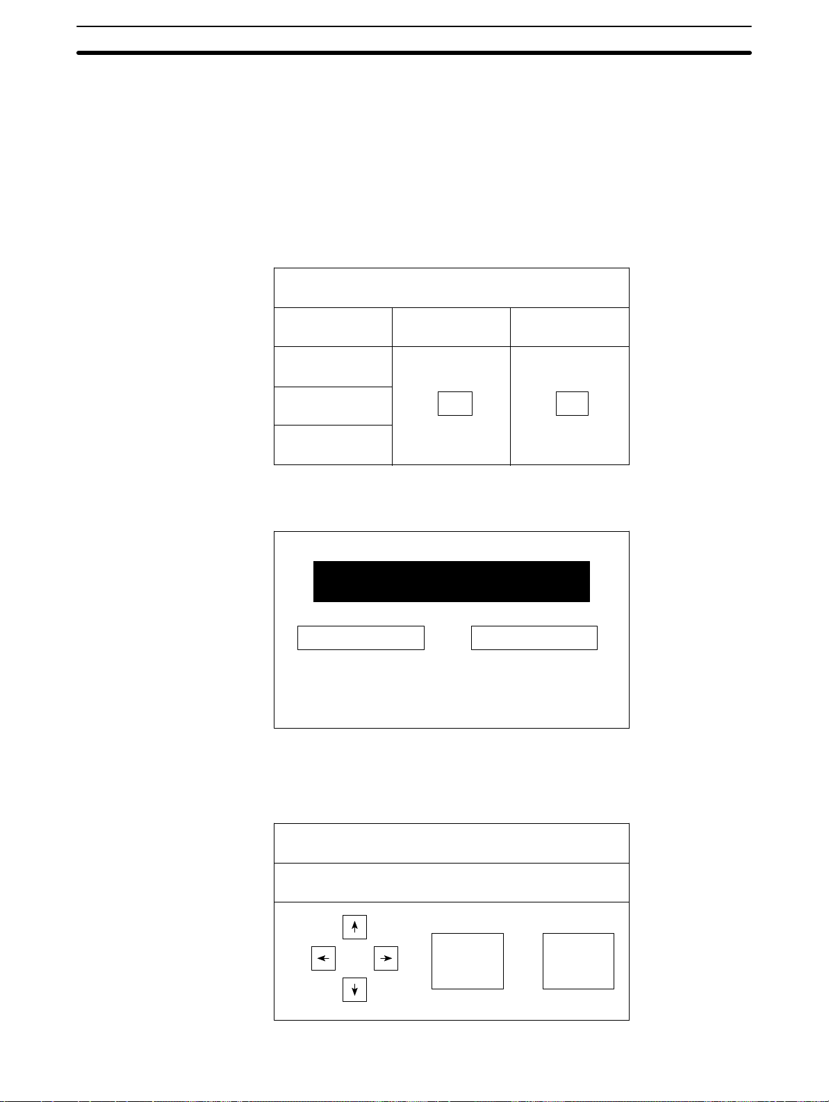
1-1-1 Operation of an NT30/30C at an FA Production Site
1-1SectionRole and Operation of NT30/30C
Production Line Status
Monitoring
Messages The NT30/30C can be used to warn of system or equipment failures and prompts
The NT30/30C can be used to display real-time information about the system
and equipment operating status, etc.
Production Control
Product
Today’s target
Current Production
% achieved
the appropriate remedial action.
NT30 NT30C
560 units
305 units
54.5 %
1994/1/25
441 units
275 units
63.0 %
Alarm
Assembly line B
–
Positioning pin
is defective.
Panel Switch Functions Setting touch switches on the NT30/30C can be set up to allow workers to use the
NT30/30C as a control panel. Production data input to the NT30/30C can be
transmitted to a PC.
Electroplating Control
Transport
Clamp UnClamp
2
Page 13
1-1SectionRole and Operation of NT30/30C
1-1-2 Operations of NT30/30C
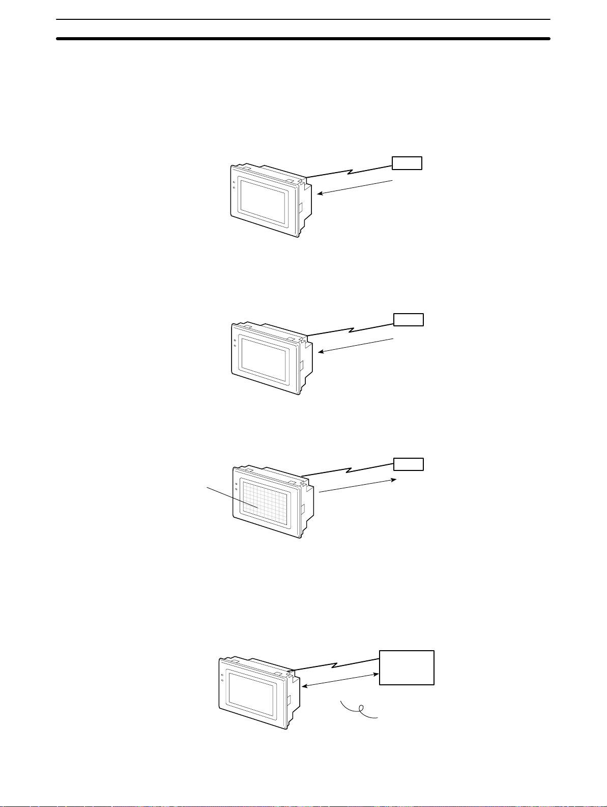
Displays Screens The information to be displayed (screen data) can be created on a computer by
using the NT-series Support Tool and stored in the NT30/30C. The screen data
can be displayed on the NT30/30C in response to the instructions from a PC/
Host or touch switch operation.
PC
The screen data designated by
instructions from PC/Host or
touch switch operation is
displayed.
Receives Data from a PC NT30/30C can be connected to a PC by a Host Link or NT Link and receive nec-
essary data from the PC.
Host Link, NT Link
PC
Sends Data to a PC Data input through a touch panel can be sent to a PC.
PC
Touch panel
ON/OFF information,
numeric data, etc.
Receives Screen Data The screen data to be displayed on the NT30/30C can be created by a computer
using the NT-series Support Tool. Connect the NT30/30C to an IBM PC/AT or
compatible with an RS-232C cable so that the screen data are transferred to the
NT30/30C.
RS-232C
Create screen data.
Screen data
IBM PC/AT or
compatible
running the
Support Tool
When using RS-232C to connect to the
PC, the connection is made only to transfer
screen data between the NT30/NT30C and
the NT-series Support Tool.
3
Page 14
1-2 Functions of NT30/30C
The NT30/30C has the following features.
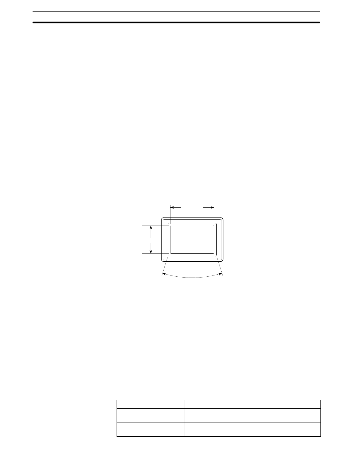
1-2-1 Features
Downsized Body
• Slim body (50 mm or less in the panel).
• The communication cable connectors are housed in the Unit so that they do
not protrude from the Unit.
• The same connector is used to connect to the the Support Tool and to the host.
Construction Best Suited to the FA Environment
• Easy-to-read screen even in direct sunlight.
• The panel is a LCD panel with white/red backlight for the NT30, and an STN
color LCD panel with backlight for the NT30C.
• Its backlight unit and battery can be replaced at the operation site.
• Waterproofed to a standard equivalent to IP65.
1-2SectionFunctions of NT30/30C
320 dots
POWER
RUN
240 dots
Wide angle of visibility, 35
Touch Switch Operation The System Menu can be displayed by using the touch switches located in four
corners of the screen.
Compatibility with
NT612G/610C
Existing screen data and user programs are compatible. (Modification required
according to screen size.)
1-2-2 Comparison between NT30 and NT30C
Two models are available: The NT30 is capable of versatile graphic displays and
the NT30C provides the same features, but is also capable of color displays. The
differences between the NT30 and NT30C are listed below.
Function NT30 NT30C
Model NT30-ST131-E (Beige)
NT30-ST131B-E (Black)
Display panel Monochrome LCD type
(with white/red backlight)
NT30C-ST141-E (Beige)
NT30C-ST141B-E (Black)
STN color LCD type
(with backlight)
4
Page 15
1-2-3 Principal Functions of NT30/30C
The following are the principal functions of the NT30/30C.
1-2SectionFunctions of NT30/30C
Data Displays
Character Displays
Characters of various sizes can be displayed. Characters can be flashed and highlighted.
Figure Displays
Solid lines, squares, polygons, circles, circular arcs, and fan shapes can be displayed. They can also be painted with various patterns, flashed, or highlighted.
Memory Data Displays
Entries in the character string memory table or numeral table can be displayed. The
memory table contents can be changed from the PC.
Graph Displays
Not only bar graphs, but also broken line graphs and trend graphs can be displayed
using the numeral table.
Lamp Displays
Lamps can be turned ON or flashed from the PC.
Alarm List Displays
In response to the status of PC bits, warning messages can be automatically listed.
When and how many times the messages appeared can also be displayed.
Data Input
Touch Switches
Data can be input by simply touching
the screen. There are various touch
switch functions, such as those for
sending input data to the PC.
Pop-up Windows
A window overlaying the currently displayed screen can be opened and
closed by pressing a touch switch. In
addition to fixed displays, numeric keys
and character keys can be set inside
the window. The window need be
opened only when input is required, to
enable effective screen usage.
Numeric V alues/Character
Strings
Touch switch keys and expanded I/O
on a B7A Unit can be allocated numeric
values or character strings so that
these values and character strings can
be input at the operation site or even
written onto the numeric or character
string table and sent to the PC. It is
also possible to disable inputs from the
PC.
System
System Functions
System settings and maintenance can be performed by selecting from system menus displayed on the screen.
Creating Screen Data
Screen data created by using the NT-series Support Tool on a personal computer
can be transferred and stored in the built-in image data memory.
System Program Installation
Using the System Installer (purchased separately), the system programs for the
NT30 and NT30C can be replaced.
Expanded I/O Functions on B7A Units
Data Output
Buzzer
A built-in buzzer can be sounded.
Screen Printing
A hard copy of the screen may be
printed to the printer connected to
the NT30/30C.
Communications
The NT30/30C communicates
with PC through a Host Interface Unit or NT Link so that
data may be received from PC
or information entered from
touch switches may be sent to
the PC.
The NT30/30C can receive a switching input from a B7A
Unit, and turns ON/OFF the output.
A B7A Interface Unit is required to connect a B7A Unit.
5
Page 16
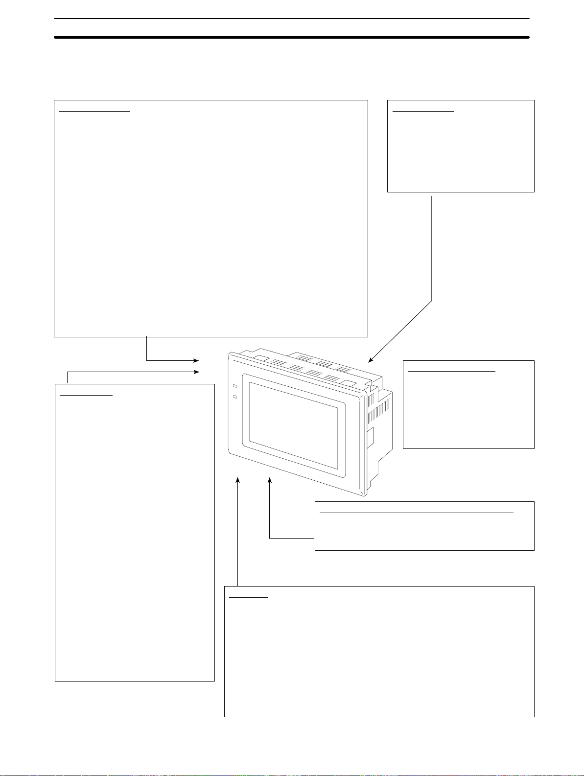
1-2-4 Displays
Characters
(character string
table)
Characters (text)
Bar graph
1-2SectionFunctions of NT30/30C
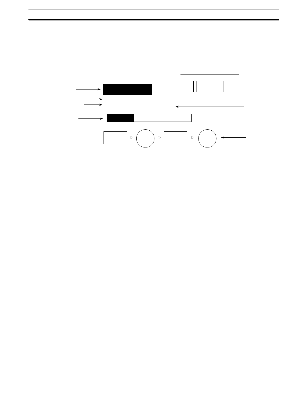
The NT30/30C can display various kinds of elements such as characters, numeric value, lamps, touch switches, and graphs on a screen. The screen data displayed on the NT30/30C are created by using the NT-series Support Tool on a
computer.
Touch
switches
Line 1 Status
Machine name: NT30C-ST141
Production qty.: 137 units
0% 50% 100%
Stop Restart
Numeric value
(numeral table)
30%
Stage 1 Stage 2
Characters (Text)
Marks and image data that do not need to be changed can be written directly to
the screen.
Characters (Character String Memory Table)
Character strings stored in the character string memory table can be displayed. The display characters can be changed by changing the data stored in
the character string memory table.
Numeric Values (Numeral Memory Table)
Numbers stored in the numeral memory table can be displayed. The display
numbers can be changed by changing the data stored in the numeral table.
Hexadecimal values can be displayed.
Lamps
Lamps can be used to indicate operating status. Squares, circles, fans, and
polygons can be used. They are controlled by the PC and can be lit (reversed)
or made to flash (alternates normal and reversed displays).
Touch Switches
Touch switches can be set anywhere on the screen. Pressing the part of the
screen where a touch switch has been set can have the following effects: No ti fication of the fact that the switch has been pressed to the PC (PC notification
function); screen switching; input of a numerical value or character string (input
key function); copying of a numerical value or character string (copy key function); shifting to another numerical value or character string input field (cursor
moving key function); and obtaining a hard copy of the screen (screen print key
function). Touch switches are controlled from the PC and can be made to light
or flash in the same way as lamps.
Check 1 Check 2
Lamps
Graphs
6
Bar graphs, trend graphs, and broken line graphs can be displayed according
to the numerical values stored in numeral memory table. These values can
also be represented as percentages displayed together with the graphs.
Page 17
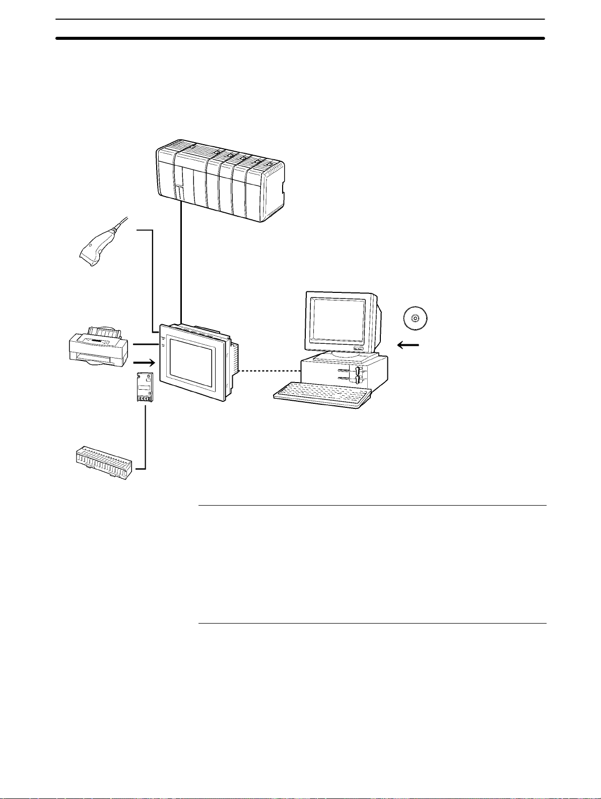
1-3 System Configuration
This section gives the basic configuration of a system that uses an NT30/30C.
Use an RS-232C cable or an RS-422A cable to connect to a PC. Refer to the
manuals for individual devices for information on devices other than the
NT30/30C in the system.
Bar code reader
Enables reading of bar
codes as character strings.
(Cannot be used with
memory link.)
RS-232C cable
(for Host Link)
(Max. 15 m)
Printer
The screen display of the
NT30/NT30C can be
printed out.
or RS-422A cable
(for Host Link)
(Max. 500 m)
OMRON PC
Controls the NT30/30C as required while controlling machines and
monitoring the production line.
Host Link: C-series PC, CVM1/CV-series PC, SRM1
NT Link: CPM1, CQM1, C200HS, C200HX/HG/HE,
NT30/30C can be connected to CPU Units, Host Link
Units, and an SRM1. Connection to some models of CPU
Unit and some models of the SRM1, however, is not
possible (see pages 23 and 40).
CVM1/CV-series PC, SRM1
NT30/30C can be connected to CPU Units and the
SRM1. Connection to some models of CPU Unit and
some models of the SRM1, however, is not possible (see
page 56).
1-3SectionSystem Configuration
NT-B7A16 B7A
Interface Unit
NT30/30C
Provides displays of production line
monitoring information and instructions to the
operation site and notifies switch ON/OFF
status and numeric value inputs to the PC.
B7A Unit
A B7A Unit can be connected to expand I/O.
Reference
NT-series Support Tool
Computer (NT-series Support Tool)
Connected to the NT30/30C as required and used to transfer
the NT30/30C screens and make settings for the NT30/30C.
Computer: IBM PC/AT or compatible
Software: NT-series Support Tool
Refer to 3-5 Setting Communications with the PC Using Memory Switches
(page 83) for setting procedures. It is impossible to connect a personal computer
running the NT-series Support Tool and a PC at the same time.
Typical optional devices for the NT30/30C include the following.
B7A Interface Unit NT-B7A16
Backlight (spare) NT30-CFL01 (for NT30)
NT30C-CFL01 (for NT30C)
Protective Sheets NT30-KBA04 (5 sheets/pack)
Battery C500-BAT08
7
Page 18

1-4 Communications Using the Direct Connection Function
1-4-1 Direct Connection Function
The communications method applied between the NT and the PC is either a Host
Link or NT Link.
The NT30/30C can be used to access data for the display or to allocate the bits
and words for storing input data in essentially any area in the PC. The NT30/30C
can directly write and read the allocated bits and words to change the display elements, control operating status, and notify status.
This function is called the direct connection function. The NT30/30C is designed
specially for use with a direct connection.
The bits and words allocated by the direct connection function are called allocated bits and allocated words.
A direct connection enables reading the data to be displayed on the NT30/30C
from a memory area in the PC and writing it to a memory table in the NT30/30C.
Also, the data input at the NT30/30C can be written to a PC memory area. The
NT30/30C screen status can be switched according to PC memory area data,
and NT30/30C status data can be written to a PC memory area.
1-4SectionCommunications Using the Direct Connection Function
Features
NT30/30C PC
DM Area IR/CIO Area
AR Area
• The bits and words used to access operating status and work instructions and
those for storing input data can be allocated in almost any part of PC I/O memory. Bits and words in the PC are accessed from memory table entries.
• The NT30/30C can directly access PC bit and word data so that it can be connected to a PC without changing the PC program that controls the current production line.
• The area to control and notify the NT30/30C status, including display screens,
display/no display status, and buzzers, can be allocated in almost any part of
PC I/O memory.
Timer/Counter
Area
The direct connection function allows the NT30/30C to directly read and write almost all bits and words in the PC and to automatically change the NT30/30C
screen display . This function can reduce the load on the PC to improve the program development efficiency of the PC.
8
Page 19

1-4-2 NT Link
Features of the NT Link
1-4SectionCommunications Using the Direct Connection Function
The NT Link is a new communications method between the PT and a PC.
The NT Link uses the direct connection function and can execute high-speed
communications with a CPM1, CPM2A, CPM2C, CQM1, CQM1H, C200HS,
C200HX/HG/HE(-Z), CS1-s e r i e s , C V M1 , C V-series, or SRM1 CPU Unit (built-in
Host Link).
• High-speed communications with specific types of PCs can be executed.
• Writing in units of bits to the PC memory area is possible (except the DM Area.
.This enables the bit in a word data to which a touch switch has been allocated
to be used for other purposes (e.g., to control a lamp).
• This can be used even when the PC is in RUN mode. (With Host Link, if the PC
is in RUN mode, the NT30/NT30C switches the mode to MONITOR mode.)
Either the NT Link or the Host Link can be used for connection without changing
the NT30/30C screen data or the PC program.
1-4-3 Functions of the Allocated Bits and Words
Elements displayed on the NT30/30C and the NT30/30C status can be allocated
to the bits and words of the PC. By changing the contents of the bits and words,
the NT30/30C can be controlled by the PC. It is also possible to send data to the
PC by pressing the touch switches on the NT30/30C.
S Controlling the NT30/30C by a PC
The following NT30/30C functions can be controlled by a PC.
Screens: Display of designated screens, confirmation
of screen numbers, etc.
Memory tables: Writing to a memory table entry, copying from
a memory table entry to another memory
table entry, etc.
Lamps and touch switches: Display instructions, confirmation of display
status, etc.
System control: Buzzer ON/OFF, display/no display status,
screen printing, and other NT30/30C statuses
S Notifying from the NT30/30C to a PC
Data in the NT30/30C is sent to a PC when a touch switch is pressed. The following types of data can be sent to the PC.
• NT30/30C status
• Touch switch status
• Numeric values and character strings input with numeral/character string
setting functions using touch switches.
• Changes in a memory table entry after copying between memory table en tries
9
Page 20

Display Elements
1-4SectionCommunications Using the Direct Connection Function
S Lamps (page 151)
Allocated to: Bits
NT30/30C
Lamp #1 (IR/CIO 000100)
Lit
Unlit
Lamp #2 (IR/CIO 000101)
PC
Switch 1: ON (IR/CIO 000100)
Switch 2: OFF (IR/CIO 000101)
The PC’s bit status can be displayed by lamps on the NT30/30C.
The lamp lights or flashes when the PC’s bit status (i.e., the lamp bit) is ON (1),
and goes OFF when it is OFF (0).
Image/library lamps can also be created to switch the displayed image or li-
brary data according to the ON (1)/OFF (0) status of the lamp bit.
S Touch Switches (page 154)
Allocated to: Bits
Touch switch #12
IR/CIO 009012
NT30/30C
PC
IR/CIO 009012: ON
The PC bit allocated for the touch switch turns ON (1) and OFF (0) when the
touch switch is pressed to notify the PC of the status of the touch switch.
S Numeral Memory Table (page 138)
Allocated to: Words
Numeral memory
table entry 1 (TIM003)
Numeral memory table entry 150 (IR/CIO 0005)
NT30/30C
PC
The numeral memory table is allocated to words in the PC. If word contents
change when corresponding numeral memory table entry is displayed on the
screen, the value on the screen will also change, enabling the contents of
words to be easily monitored.
10
Reading and writing are executed so that the contents of allocated words are
kept the same as those of the numeral memory table entries.
Page 21
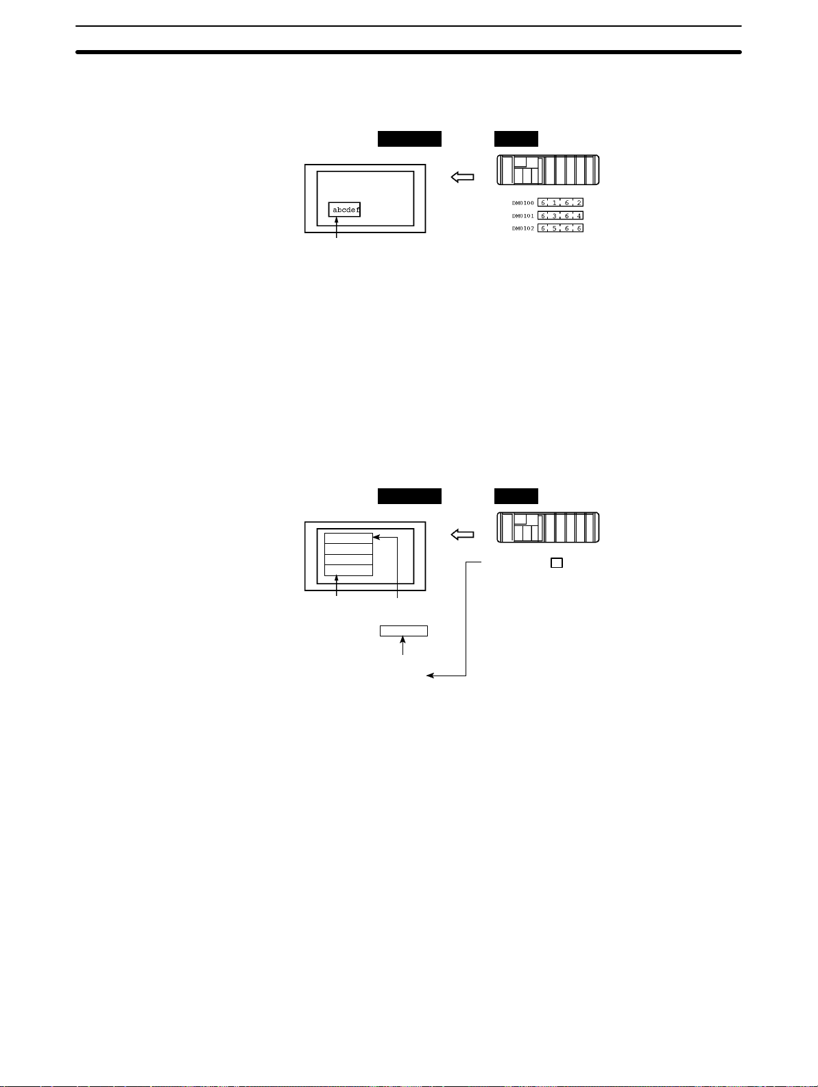
S Character String Memory Table (page 136)
Allocated to: Words
NT30/30C PC
(“a”, “b”)
(“c”, “d”)
(“e”, “f”)
Character string memory table entry 1
Number of words allocated: 3 words
First word: DM0100
The character string memory table is allocated to words in the PC. If word contents change when the corresponding character string memory table entry is
displayed on the screen, the value on the screen will also change, enabling
messages to be easily displayed.
Reading and writing are executed so that the contents of allocated words are
kept the same as those of the character string memory table entries.
1-4SectionCommunications Using the Direct Connection Function
S Alarm List (Bit Memory Table) (pages 140 and 180)
Allocated to: Bits
NT30/30C PC
Material low
1
Alarm list
Character string memory
table entry 120
Material low
Bit memory table entry 23
IR/CIO 010009
Character string memory
table entry 120
IR/CIO 010009
When the corresponding PC bit turns ON (1), the contents of the character
string memory table entry registered for the bit memory table entry is displayed
in the alarm list. When the bit returns to the OFF (0) status, the character string
memory table entry display is automatically cleared.
11
Page 22
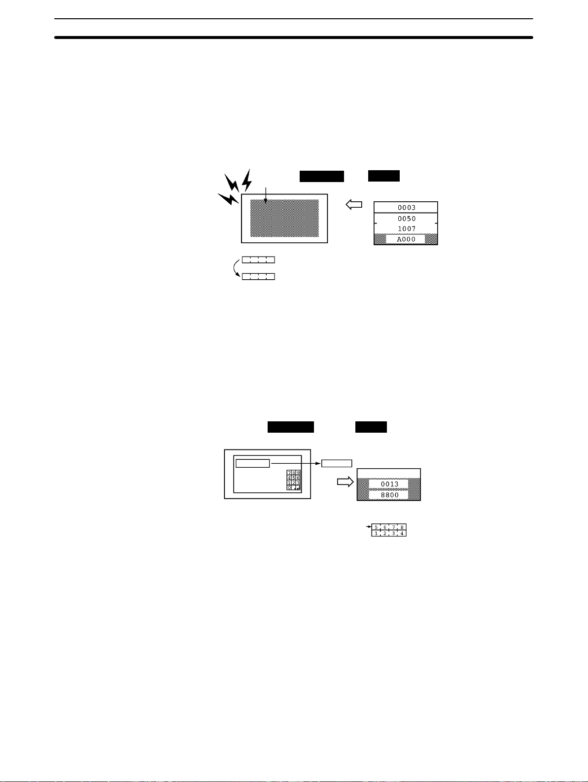
PT Status Control Area (PC to NT30/30C)
The PT Status Control Area is used to control the NT30/30C status. When data is
written to th is area in the PC, the NT30/30C reads the contents and operates according to the contents.
Example of PT Status Control Area Application
When data is written to the PT Status Control Area, the NT30/30C will operate as
illustrated below (page 191).
1-4SectionCommunications Using the Direct Connection Function
Continuous
buzzer sound
Copy
PT Status Notify Area (NT30/30C to PC)
The PT Status Notify Area is used to notify the PC of changes in the NT30/30C
status. When a change is made in the NT30/30C status, the change is written to
this area in the PC. By reading the data from the area, the NT30/30C status can
be checked from the PC.
Example of PT Status Notify Area Application
When a change is made in the NT30/30C status, the change will be indicated in
the PT Status Notify Area as illustrated below (page 193).
Screen 3
display
Numeral memory table entry 50
Numeral memory table entry 7
NT30/30C
12345678
NT30/30C
Numeral memory table entry 13
12345678
PC
PT Status Control Area
Screen switch setting
Memory table entry
Copy setting
PT status control bits
PC
PT Status Notify Area
Currently display screen
Content update memory table entry
PT status
12
Allocated word (numeral table entry 13)
12345678
Start
Start + 1
Page 23
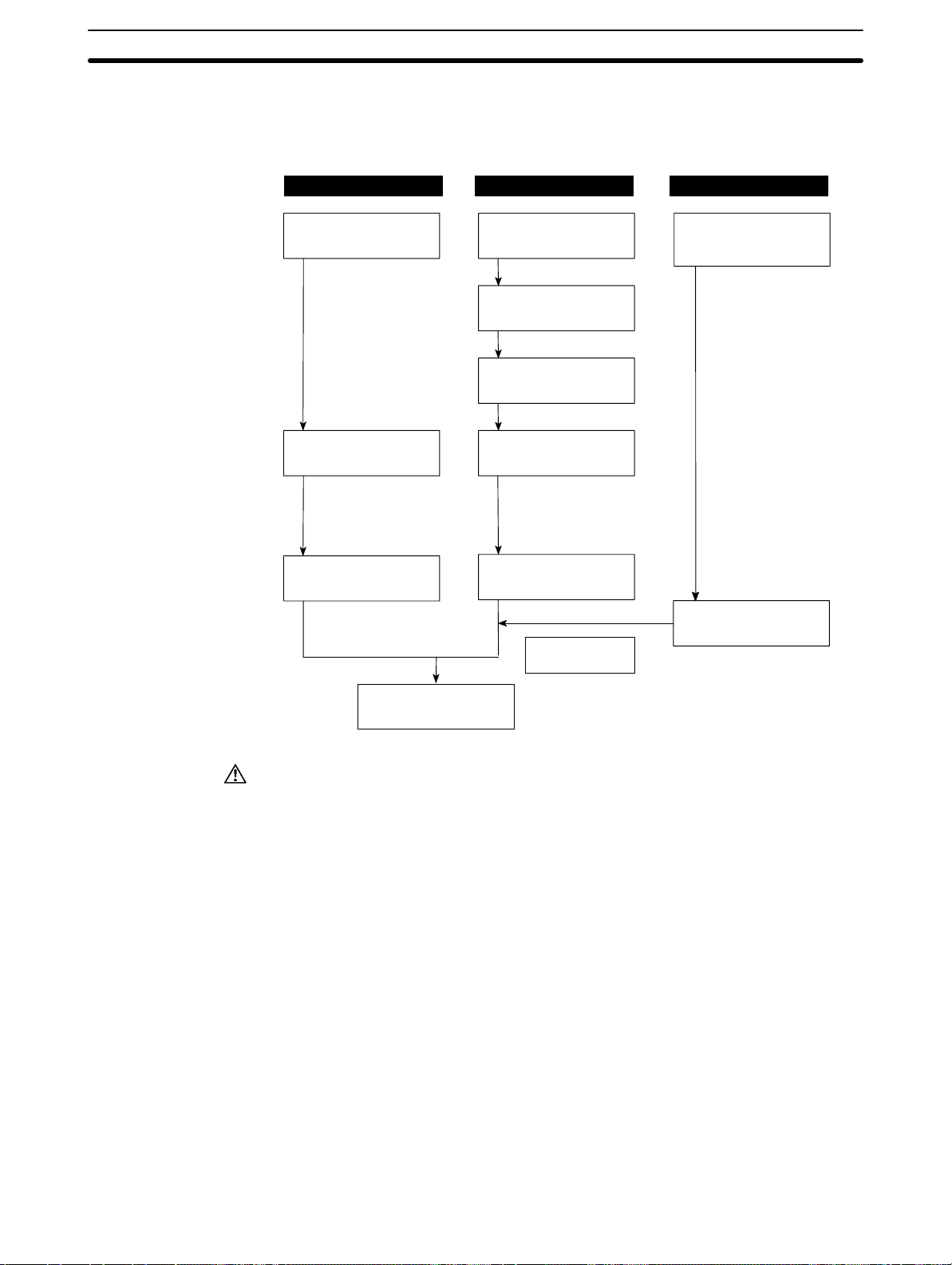
1-5 Before Operating
Use the procedure given below to start the NT30/30C.
1-5SectionBefore Operating
PC NT30/30C NT-series Support Tool
Check and change
the PC settings.
For the Host Link, refer
to page 27 (RS-232C),
page 40 (RS-422A)
and the manuals for
the Host Link Unit and
Programming Devices.
For the NT Link,
refer to page 56.
Connect to the
NT30/30C.
Create the PC
program.
Start operation.
Set the DIP switch.
(page 18)
Install to the operation panel.
(page 19)
Connect the power
supply.
(page 20)
Connect to the PC.
(Host Link:
page 25 (RS-232C)
page 42 (RS-422A))
(NT Link: page 56)
Check the settings
and communications.
Transfer the
screen data.
(page 89)
Install NT-series
Support Tool on the
computer.
(Refer to the manuals
for the NT-series
Support Tool.)
Create the screens.
(Refer to Section 4 and
the manuals for the
NT-series Support Tool.)
Caution
Be sure to confirm that correct operation is possible with the screen data and the
host program before actual operation.
Reference 1. Use the System Installer provided with the NT-series Support Tool for Win-
dows.
2. Use the NT-series Support Tool for Windows.
13
Page 24

Refer to the following manuals for the product information.
Product Manual Title Cat No.
System Installer NT-series Support Tool for Windows Operation Manual
NT-series Support Tool NT-series Support Tool Operation Manual
NT-series Support Tool for Windows Operation Manual
PCs SYSMAC CPM1 Operation Manual
SYSMAC CPM1A Operation Manual
SYSMAC CPM2A Operation Manual
SYSMAC CPM2C Operation Manual
SYSMAC C20H/C28H/C40H/C60H Programming Manual
SYSMAC C200H Operation Manual (CPU01-E/03-E/11-E)
SYSMAC C200H Operation Manual (CPU21-E/23-E/31-E)
SYSMAC C200HS Operation Manual
SYSMAC C200HS Installation Guide
SYSMAC C200HX/HG/HE-CPU-E/ZE Installation Guide W302-E1-
SYSMAC C200HX/HG/HE Operation Manual
SYSMAC C1000H/C2000H Operation Manual
SYSMAC C200HX/HG/HE-CPU-ZE Operation Manual W322-E1-
SYSMAC CQM1 Reference Manual
SYSMAC CQM1H Operation Manual
SYSMAC CV500/CV1000/CV2000 Operation Manual: Ladder
Diagrams
* For a PC of the CVM1 Series, refer to the SYSMAC
CV500/CV1000/CV2000 Operation Manual.
SYSMAC CS1-series Operation Manual
SYSMAC CS1-series Programming Manual
CompoBus/S
Master Control Unit
Programming Devices SYSMAC C-series and CVM1 PCs SYSMAC Support Software
Host Link Unit SYSMAC C-series Host Link Unit Operation Manual
SRM1 Operation Manual
Operation Manual: C-series PCs
SYSMAC C-series and CVM1 PCs SYSMAC Support Software
Operation Manual: CVM1 PCs
CX-Programmer Operation Manual ---
SYSMAC CVM1/C-series Host Link Operation Manual
1-5SectionBefore Operating
V061-E1-
V028-E1-
V061-E1-
W262-E1-
W317-E1-
W352-E1-
W356-E1-
W176-E1-
W130-E1-
W217-E1-
W235-E1-
W236-E1-
W303-E1-
W140-E1-
W228-E1-
W363-E1-
W202-E1-
W339-E1-
W340-E1-
W318-E1-
W248-E1-
W249-E1-
W143-E1-
W205-E1-
14
Page 25

SECTION 2
Hardware Settings and Connections
This section describes the settings of the NT30/30C, connections to a PC, and other hardware settings.
2-1 Description of Parts and Settings 16. . . . . . . . . . . . . . . . . . . . . . . . . . . . . . . . . . . . . . . . . . . . .
2-1-1 Description of Parts 16. . . . . . . . . . . . . . . . . . . . . . . . . . . . . . . . . . . . . . . . . . . . . . . .
2-1-2 DIP Switch Settings 18. . . . . . . . . . . . . . . . . . . . . . . . . . . . . . . . . . . . . . . . . . . . . . . .
2-2 Installation 19. . . . . . . . . . . . . . . . . . . . . . . . . . . . . . . . . . . . . . . . . . . . . . . . . . . . . . . . . . . . . .
2-2-1 Installation to the Operation Panel 19. . . . . . . . . . . . . . . . . . . . . . . . . . . . . . . . . . . .
2-2-2 Power Supply Connection 20. . . . . . . . . . . . . . . . . . . . . . . . . . . . . . . . . . . . . . . . . . .
2-2-3 Ground Wire Connection 21. . . . . . . . . . . . . . . . . . . . . . . . . . . . . . . . . . . . . . . . . . . .
2-3 Connecting to the Support Tool 21. . . . . . . . . . . . . . . . . . . . . . . . . . . . . . . . . . . . . . . . . . . . . .
2-4 Installing the System Program 22. . . . . . . . . . . . . . . . . . . . . . . . . . . . . . . . . . . . . . . . . . . . . . .
2-5 Connection to a PC by Host Link via RS-232C 23. . . . . . . . . . . . . . . . . . . . . . . . . . . . . . . . . .
2-5-1 Compatible PCs 23. . . . . . . . . . . . . . . . . . . . . . . . . . . . . . . . . . . . . . . . . . . . . . . . . . .
2-5-2 Connecting the NT30/30C 25. . . . . . . . . . . . . . . . . . . . . . . . . . . . . . . . . . . . . . . . . . .
2-5-3 PC Switch Settings 27. . . . . . . . . . . . . . . . . . . . . . . . . . . . . . . . . . . . . . . . . . . . . . . . .
2-6 Connection to a PC by Host Link via RS-422A 40. . . . . . . . . . . . . . . . . . . . . . . . . . . . . . . . .
2-6-1 Compatible PCs 40. . . . . . . . . . . . . . . . . . . . . . . . . . . . . . . . . . . . . . . . . . . . . . . . . . .
2-6-2 Parts Required for Connection 42. . . . . . . . . . . . . . . . . . . . . . . . . . . . . . . . . . . . . . . .
2-6-3 Method for Connection 42. . . . . . . . . . . . . . . . . . . . . . . . . . . . . . . . . . . . . . . . . . . . .
2-6-4 Connector Specifications and Wiring for Each Unit 43. . . . . . . . . . . . . . . . . . . . . . .
2-6-5 PC Switch Settings 48. . . . . . . . . . . . . . . . . . . . . . . . . . . . . . . . . . . . . . . . . . . . . . . . .
2-7 Connection to a PC by the NT Link 56. . . . . . . . . . . . . . . . . . . . . . . . . . . . . . . . . . . . . . . . . . .
2-7-1 Compatible PCs 56. . . . . . . . . . . . . . . . . . . . . . . . . . . . . . . . . . . . . . . . . . . . . . . . . . .
2-7-2 Connecting the NT30/30C 58. . . . . . . . . . . . . . . . . . . . . . . . . . . . . . . . . . . . . . . . . . .
2-7-3 PC Switch Settings (RS-232C at PC Side) 59. . . . . . . . . . . . . . . . . . . . . . . . . . . . . .
2-7-4 PC Switch Settings (RS-422A at PC Side) 61. . . . . . . . . . . . . . . . . . . . . . . . . . . . . .
2-8 Connecting a Printer 63. . . . . . . . . . . . . . . . . . . . . . . . . . . . . . . . . . . . . . . . . . . . . . . . . . . . . . .
2-8-1 How to Connect 64. . . . . . . . . . . . . . . . . . . . . . . . . . . . . . . . . . . . . . . . . . . . . . . . . . .
2-9 Connection of Expanded I/O 64. . . . . . . . . . . . . . . . . . . . . . . . . . . . . . . . . . . . . . . . . . . . . . . .
2-9-1 Connectable B7A Units 64. . . . . . . . . . . . . . . . . . . . . . . . . . . . . . . . . . . . . . . . . . . . .
2-9-2 B7A Interface Unit Specifications 65. . . . . . . . . . . . . . . . . . . . . . . . . . . . . . . . . . . . .
2-9-3 B7A Interface Unit Part Names 66. . . . . . . . . . . . . . . . . . . . . . . . . . . . . . . . . . . . . . .
2-9-4 Installing the B7A Interface Unit 66. . . . . . . . . . . . . . . . . . . . . . . . . . . . . . . . . . . . .
2-9-5 B7A Interface Unit Settings 67. . . . . . . . . . . . . . . . . . . . . . . . . . . . . . . . . . . . . . . . . .
2-9-6 Connecting the B7A Unit to the B7A Interface Unit 67. . . . . . . . . . . . . . . . . . . . . .
15
Page 26
2-1 Description of Parts and Settings
Before getting to the operation, confirm the names and functions of parts. Also
set the DIP switch on the NT30/30C.
2-1SectionDescription of Parts and Settings
Caution
On unpacking the NT30/30C, check its external appearance and confirm that
there is no d a m age. Also confirm that there is no abnormal noise on shaking the
Unit lightly. The product may malfunction if it is damaged.
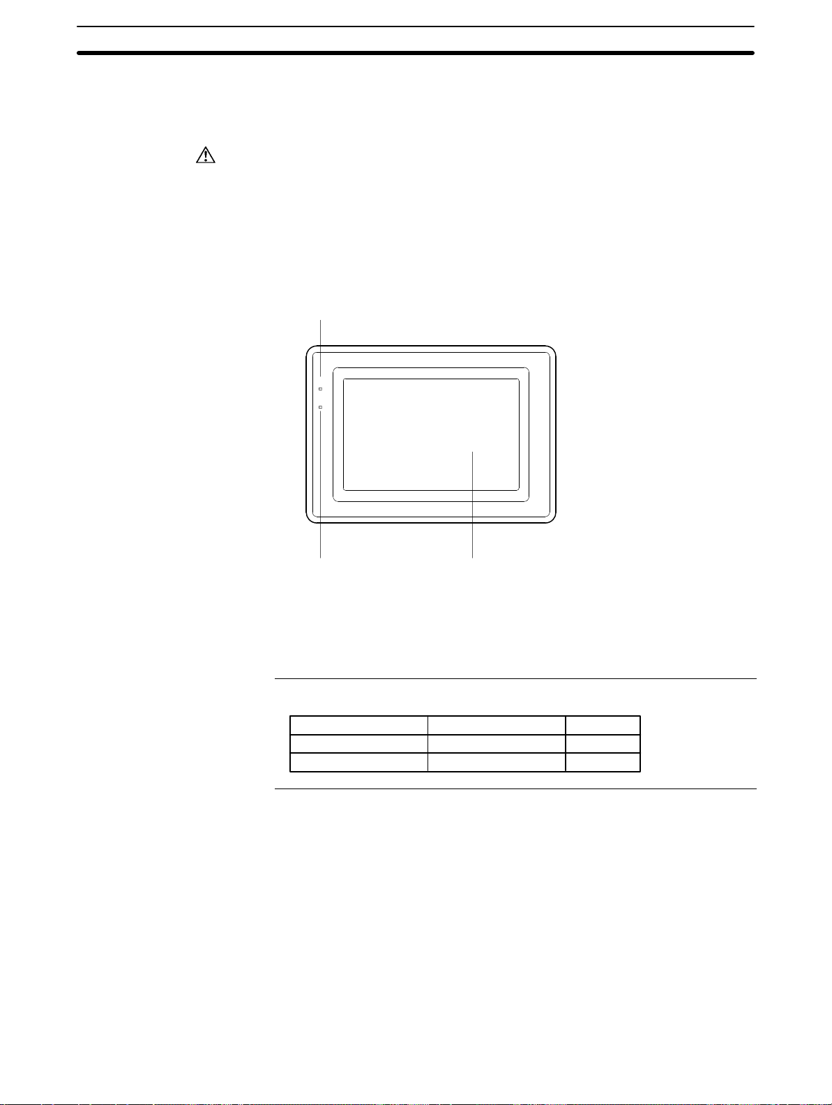
2-1-1 Description of Parts
Front View
POWER indicator
Lit when the power is
supplied.
POWER
RUN
Reference
RUN indicator
Lit in green while the PT
is in the RUN mode.
Lit in orange or red when
the battery is low (orange
in the RUN mode, red in
other modes)
Display
The NT30 has a monochrome LCD screen
with a white/red backlight, and the NT30C
has an STN color LCD screen. The whole
area of the screen is a touch panel that
works as an input device.
The NT30/30C comes in two body colors.
NT30 NT30C Body Color
NT30-ST131-E NT30C-ST141-E Beige
NT30-ST131B-E NT30C-ST141B-E Black
16
Page 27
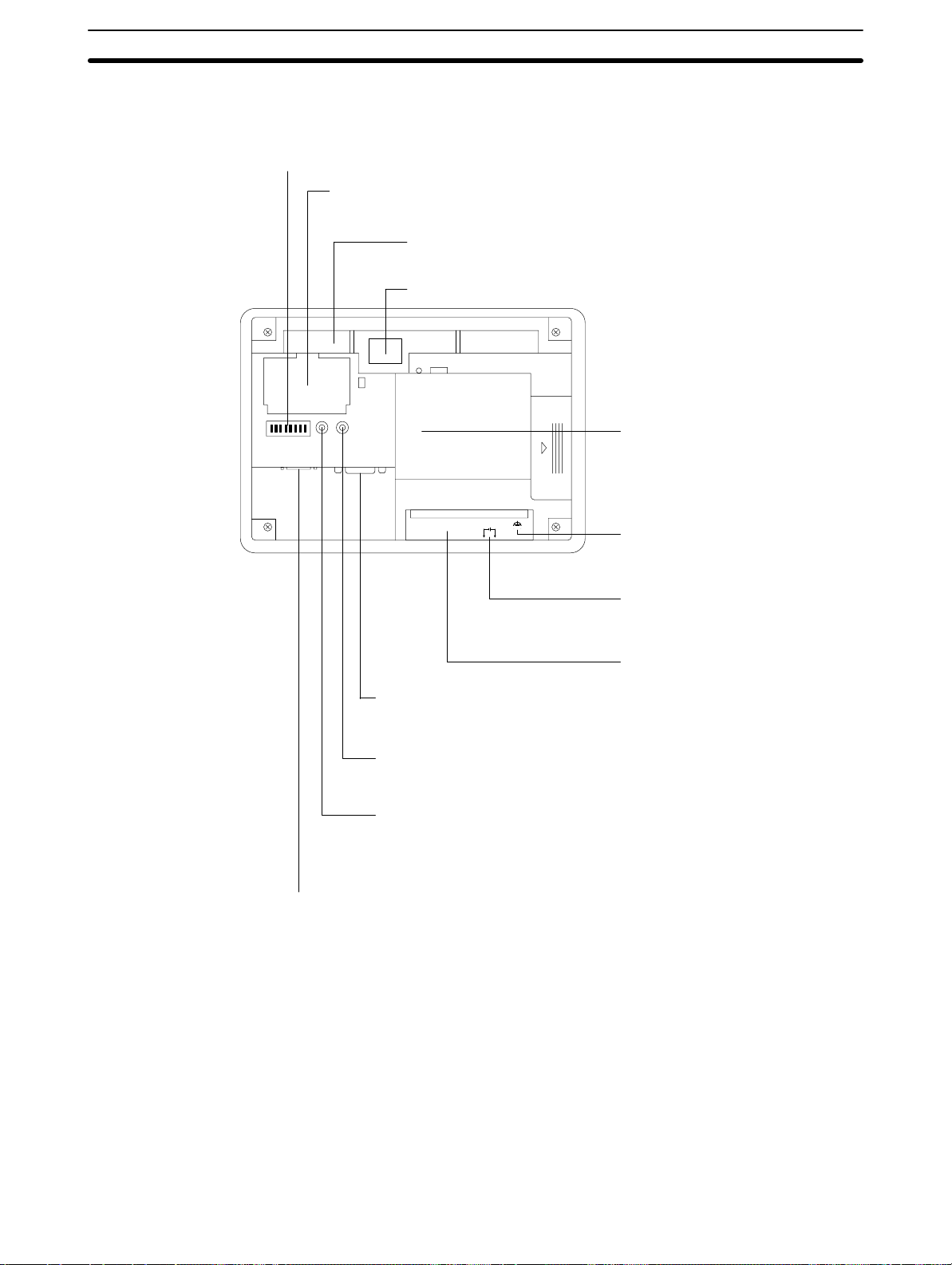
Rear View
2-1SectionDescription of Parts and Settings
DIP switch (SW2)
Set the system settings with
this DIP switch.
Battery cover
The battery is secured underneath this cover.
Backlight unit
Backlight integrated with a connector.
Warning label
SW2 RESET –CONTRAST
PRINTER RS-232C
B7A interface connector (under the
label)
When using a B7A Interface Unit, peel
off the label and connect it here.
SDA SDB RDA RDB
24 VDC
+
GR terminal
Grounding terminal to prevent
malfunction due to noise
Power input terminals
Connect the power to the NT30/30C
at these terminals.
RS-422A terminal block
When making the connection to the PC
RS-232C Host I/F tool connector
with RS-422A, connect the cable here.
Connect the cable from a PC or
NT-series Support Tool here.
Contrast control
Use a fine flat-blade screwdriver. Turn
clockwise to increase the brightness.
Reset switch
Used to initialize all the statuses of the NT30/30C.
However, the screen data memory and memory
switches retain their statuses before initialization.
Printer connector
Connect the printer cable here. Output
conforms to Centronics specifications.
17
Page 28
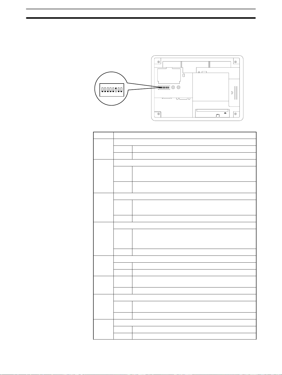
2-1-2 DIP Switch Settings
Set the NT30/30C operation status with the DIP switch located in the bottom right
corner on the rear side of the body.
ON
12345678
2-1SectionDescription of Parts and Settings
SW2 RESET –CONTRAST
PRINTER RS-232C
SDA SDB RDARD
24 VDC
+
B
Pin Function
1 Not used.
ON
[OFF]
2 Memory protect
ON Data cannot be written to the screen data memory, and screen
data transmission and initialization of the screen data memory
are not possible.
[OFF] Screen data transmission and screen data memory initialization
are not possible.
3 Switching to the System Menu enabled/disabled
ON The System Menu cannot be displayed. If an error occurs dur-
ing a start-up, the System Menu will be automatically displayed.
However, RUN Mode cannot be entered.
[OFF] The System Menu can be displayed.
4 Screen data initialize effective/ineffective
ON The NT30/30C will start in a special RUN mode in which the
screen data memory is initialized. When it is started, the
memory initialization menu will be displayed. For the initialization procedure, refer to 3-4 Initializing Memory (page 78).
[OFF] The NT30/30C will start in normal RUN mode.
5 Not used.
ON
[OFF]
6 [ON] When you set the DIP switch pin 7 ON, NT-series System
Installer messages are displayed in English.
OFF Messages are displayed in Japanese
7 System installation effective/ineffective
ON System program installation is effective (special mode) at the
time when the power turn ON.
[OFF] Starts normal RUN mode.
8 Terminator setting when using RS-422A
ON When connecting to the PC with RS-422A
[OFF] When connecting to the PC with RS-232C
18
[ ] indicates factory setting.
Page 29

2-2SectionInstallation
Caution
Reference
2-2 Installation
Correct use
If the DIP switch settings have been changed when the NT30/30C is powered,
reset the power to the NT30/30C. The changes with the DIP switches become
effective only after the power supply is reset. Before switching ON the power for
the first time, set DIP switch pin 6 of the NT30/30C to ON (they are set to OFF on
shipping). If they are left OFF, messages will not be displayed normally.
In addition to the DIP switch settings, set also the host communications, port,
baud rate, etc., in the memory switches. For these settings, refer to 3-5 Setting
the Conditions of Communications with the PC by Using the Memory Switches
(page 83).
Install the NT30/30C to the operation panel and connect the power to the
NT30/30C as described below.
Do not install the NT30/30C at sites subject to the following conditions.
Otherwise, the product may malfunction.
- Severe temperature variations
- Temperatures or humidities outside the ranges stated in the specifications
- High humidity, condensation
- Splashing chemical agents
- Severe oil splashing
- Corrosive or flammable gases
- Strong vibrations or shocks
- Direct exposure to wind and rain (outdoor sites)
- Strong ultra-violet irradiation
Take adequate measures to ensure shielding if the NT30/30C is used at a
location subject to any of the following conditions. Otherwise, the product may
malfunction.
- Static electricity, or noise from other equipment
- Strong electromagnetic fields
- Nearby power cables
- Potential exposure to radioactivity
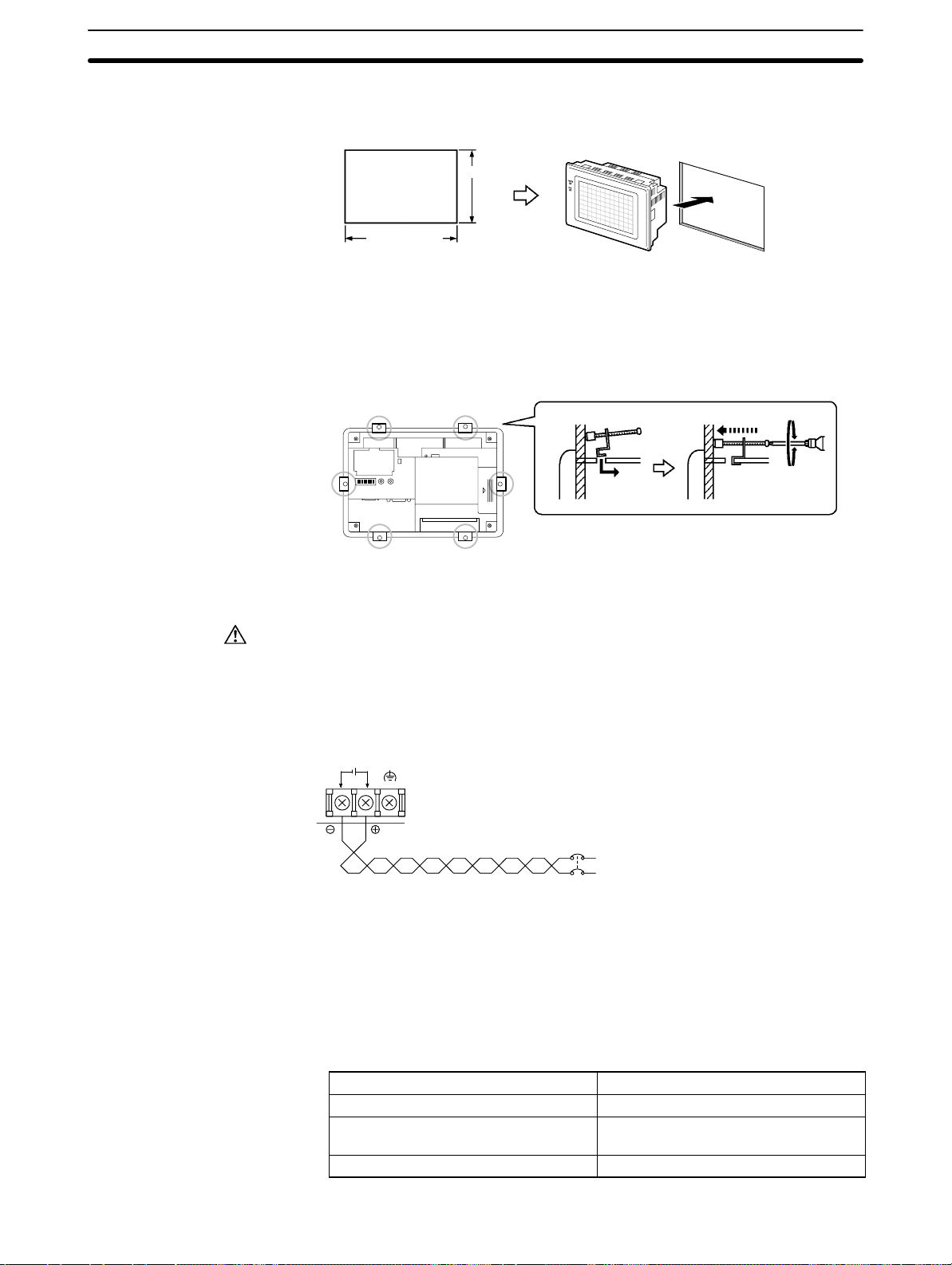
2-2-1 Installation to the Operation Panel
The NT30/30C is mounted on an operation panel by embedding it in the panel.
Use the panel fittings and tools included in the product package and follow the
procedure below.
Caution
During work at the panel, take care to ensure that no metal scraps enter the
Unit. Otherwise, the product may malfunction.
The thickness of applicable operation panel is 1.6 mm to 4.8 mm. All fittings
must be tightened uniformly to a torque of 0.5 to 0.6 Nm in order to ensure
water- and dust-resistance. The panel must not be soiled or warped, and must
be able to support an installation that will remain secure and strong.
19
Page 30
2-2SectionInstallation
(1) Open a hole, shown below , in the panel and install the NT30/30C from the
front side of the panel.
+0.5 mm
131.0
0 mm
+0.5 mm
184.0
0 mm
(2) Attach the panel fittings at four positions for the upper/lower sides and at two
positions for the right and left sides, shown below, on the rear side of the
NT30/30C.
Fit the hook of the fitting in the square hole in the body and tighten the screw
with a Phillips head screwdriver while lightly pulling the fitting.
SW2 RESET –CONTRAST
PRINTER RS-232C
2-2-2 Power Supply Connection
Connect a 24 VDC power supply to the power input terminals.
Caution
Do not apply an AC power supply across the power supply terminals.
Use a DC power supply with a low voltage fluctuation stipulation
When complying with EC directives (low voltage directives) use a power sup-
ply with reinforced insulation.
Carefully check the wiring before switching ON the power.
24 VDC
+
S Noise Prevention
The NT30/30C has a noise preventive feature against the power supply line
noise. To further reduce noise, connect a noise filter to the power line.
SDA SDBRD
24 VDC
RDB
A
Breaker
24 VDC Power Supply
20
S Power Supply
In order to comply with EC directives, use a SELV power supply.
Applicable power supply specifications are as follows.
Item Value
Power supply voltage 24 VDC
Allowable power supply voltage
fluctuation range
Power supply capacity 15 W or over
20.4 VDC to 26.4 VDC
(24 VDC –15%, +10%)
Page 31

S Parts Used for Connection
Caution
For the connection to the power supply terminal block, twisted wires of 2 mm
or greater cross sectional area and M 3.5 size crimp terminals must be used.
Tighten the screws on the terminal block to a torque of 0.8 Ncm.
Otherwise fire may occur.
Use crimp terminals to connect the power supply to the power input terminals.
Recommended crimp terminals for M3.5 are given below.
7 mm or less 7 mm or less
2-2-3 Ground Wire Connection
The NT30/NT30C has a functional ground terminal. T o prevent malfunctions due
to excessive noise, or to prevent electric shocks, wire the NT30/NT30C to a
ground of 100 Ω or less using a separate ground wire (2 mm
wire should be connected to a point at a distance of 20 m or less. Do not use the
same ground wire for other devices, or connect the ground wire to a beam in a
building. To further reduce the influence of noise, connect a noise filter.
Fork type Round type
2-3SectionConnecting to the Support Tool
2
min.). The ground
2
NT30/
NT30C
Connect to a
ground of
100 Ω or
less.
Provide separate ground wires.
Correct use
Other
devices
In order to prevent malfunctions due to noise, perform grounding correctly.
NT30/
NT30C
Other
devices
Do not use a common ground wire.
2-3 Connecting to the Support Tool
Connect the NT30/30C to a computer with an RS-232C cable to transfer the
screen data created by using the NT-series Support Tool to the NT30/30C.
An NT30/30C cannot be connected to both a personal computer running the NTseries Support Tool and a PC at the same time. Connect the personal computer
only when transmitting screen data.
SW2 RESET –CONTRAST
PRINTER RS-232C
NT30/
NT30C
Other
devices
SDA SDBRD
24 VDC
RDB
A
21
Page 32

S Communication Conditions
NT Link (1:1)
NT30C-ST141(B)-EV1 at the time of
Communication conditions are set when the NT-series Support Tool is started.
S Recommended Connecting Cable
Use the cables indicated below.
CV500-CN228 (length: 2 m), made by OMRON
(D-sub, 9-pin, male ↔ D-sub, 25-pin, male)
XW2Z-S001 (conversion cable), made by OMRON
(D-sub, 25-pin, female ↔ Half-pitch, 14-pin, male, used together with the
CV500-CN228)
XW2Z-S002 (length: 2 m), made by OMRON
(D-sub, 9-pin, male ↔ D-sub, 9-pin, female, for IBM PC/AT or compatible
computer)
To make a connector cable, refer to the appendix Connecting Cable Specifica-
tions (page 281).
2-4 Installing the System Program
With the NT30/NT30C, the system program is not fixed and can be installed (or
re-installed). This means that the system program can be easily replaced when
grading up or changing the system configuration.
2-4SectionInstalling the System Program
Reference
If the system program is erased, it will become completely impossible to use
the NT30/NT30C without reinstalling the system program. Before erasing the
system program, confirm that the System Installer and the system program
are at hand. Screen data and memory switch settings, however, will be saved.
The following software is used to install the system program.
S System Installer
Model Number Communications Method Remarks
NT30-ZS3PC-EV1 Host Link
NT30-ZS3DV-EV1
NT-ZJCMX-EV4 Host Link
Reference
NT Link (1:1)
The system program that is included in the NT30-ZS3-EV1 is installed in
the NT30/NT30C at the time of delivery.
All of the system programs and System Installers required for the
NT30/NT30C are provided with the NT-series Support Tool for Windows
(Ver. 4).
A simple explanation of the system program installation method is given here.
For a detailed explanation about setting up System Installer on a computer and
System Installer operations, refer to the manual provided with the System
Installer.
S Installing the System Program
Install the system program onto the NT30/NT30C using the following procedure.
(1) Initialized the NT30/NT30C
If another system program is already installed, erase that system program
first.
With the power supply to the NT30/NT30C turned OFF, turn ON DIP switch
(SW2) pin 7 and then turn ON the power supply. When the confirmation message is displayed, execute erasing the system program
Installed in the NT30-ST131(B)-EV1/
-S
delivery.
For Windows
-
22
Page 33

2-5SectionConnection to a PC by Host Link via RS-232C
(2) Put the NT30/NT30C on Standby for Installation
Turn OFF the power supply and return DIP switch pin 7 that was turned ON
in step 1 to OFF. After that, turn ON the power supply again. The
NT30/NT30C will go into standby, waiting for system program installation.
(3) Transfer the System Program
Connect the NT30/NT30C to the computer, start up System Installer, and
transfer and install the system program.
For details of operation, refer to the manual provided with the System
Installer.
S System Installer Settings
In the System Installer settings, specify the type of PT to which the system program is installed.
Specify either NT30 or NT30C as the PT model (with DOS versions, the setting
is as the NT-series model under the tool settings). Make other settings according
to the operating conditions of the System Installer.
S Selecting the System Program to be Transferred
Select the name of the desired system program from the communications methods displayed in the system program list in the System Installer.
For details, refer to the the manual provided with the System Installer.
2-5 Connection to a PC by Host Link via RS-232C
Connect the NT30/30C to an OMRON PC by using the RS-232C Host Link method.
In order to make a connection to the PC using the Host Link method via
RS-232C, the host communications memory switch of the NT30/30C must be set
to Host Link, and the port memory switch must be set to RS-232C. For details on
memory switch settings, see Selecting the Host Communication Method
(page 85) and Selecting the Host Link Communication Port (page 87).
2-5-1 Compatible PCs
Some models and series of OMRON PCs have the Host Link function built in.
With CS1-series and CQM1H PCs, Host Link communications are possible by
adding a Serial Communications Board. Also, there are some C200HX/HG/HE
CPU Units that support Host Link communications when a Communications
Board is mounted.
Check the model and series of the PC, and the model of Communications Board
mounted, before making connections.
The PCs that can be connected by Host Link via RS-232C are listed in the table
below.
23
Page 34

2-5SectionConnection to a PC by Host Link via RS-232C
CO 0 /0 /05/06
PC Series CPU Units with the Host Link
CS1G-CPU42/43/44/45 (-EV1)
CS1 Series
C Series
CV series (*3) CV500-CPU01-EV1 CV500-CPU01-EV1 CV500-LK201 CV500
CVM1 series
(*3)
CompoBus/S
Master Control Unit
CS1H-CPU63/64/65/66/67
(-EV1)
C20H/C28H/C40H/C60H --- ---
---
---
C200HS-CPU21/23/31/33 --- --- C200HS
C200HE-CPU42-(Z)E C200HE-CPU32/42-(Z)E
C200HG-CPU43/63-(Z)E C200HG-CPU33/43/53/63-(Z)E
C200HX-CPU44/64/65/85-(Z)E
---
---
CPM1-10/20/30CDR- +
CPM1-CIF01
CPM1A-10/20/30/40CD- +
CPM1-CIF01
CPM2A-30/40/60CD- +
CPM1-CIF01 (when connected
via peripheral port)
CPM2C-10/20-
(*1)
CQM1-CPU21-E
CQM1-CPU41/42/43/44(-EV1)
CQM1H-CPU11/21/51/61-E (*2) CQM1H-CPU51/61-E CQM1H-SCB41 CQM1H
CV1000-CPU01-EV1 CV1000-CPU01-EV1 CV1000
CV2000-CPU01-EV1 CV2000-CPU01-EV1 CV2000
CVM1-CPU01-EV
CVM1-CPU11-EV
CVM1-CPU21-EV
SRM1-C02-V2 --- --- SRM1
Function Built In
CPU Units Connectable Using
a Host Link Unit or Communica-
tions Board
CS1G-CPU42/43/44/45 (-EV1)
CS1H-CPU63/64/65/66/67
(-EV1)
C1000H-CPU01-EV1
C2000H-CPU01-EV1
C200HSCPU01/03/21/23/31/33-E
C200HE-CPU11/32/42-(Z)E
C200HG-CPU33/43/53/63-(Z)E
C200HX-CPU34/44/54/64-(Z)E
C200HXCPU34/44/54/64/65/85-Z
C1000H-CPU01-EV1
C2000H-CPU01-EV1
C1000H-CPU01-EV1
C1000HF-CPUA1-EV1
C2000H-CPU01-EV1
--- ---
--- ---
--- --- CPM2A
--- --- CPM2C
--- --- CQM1
CVM1-CPU01-EV
CVM1-CPU11-EV
CVM1-CPU21-EV
Host Link Unit or
Communications
Board
CS1W-SCU21
CS1W-SCB21
CS1W-SCB41
C120-LK201-V1
C200H-LK201-V1
C200HWCOM02/04/05/06-V1
C500-LK201-V1
C500-LK203
CV500-LK201 CVM1
Connect-
able PC
CS1G
CS1H
CH
C1000H
C2000H
C200HS
C200HE
C200HE-Z
C200HG
C200HG-Z
C200HX
C200HX-Z
C200HE
C200HE-Z
C200HG
C200HG-Z
C200HX
C200HX-Z
C1000H
C2000H
C1000H(F)
C2000H
CPM1
(*1) The CPM2C-CN111 or CS1W-CN114/118 Connecting Cable, or the CPM1-CIF01 RS-232C Adapter is re-
(* 2) The CQM1H-CPU11 is not equipped with an RS-232C port, so connect to the CS1W-CN118 Connecting
(* 3) CVM1/CV-series CPU Units without “-V” at the end of the model number cannot be directly connected.
24
quired.
Cable, and connect the peripheral port of the CS1W-CN118 to the PT.
With these CPU Units, connect to the PT using a Host Link Unit.
Page 35

2-5-2 Connecting the NT30/30C
Refer to the illustrations below to select the appropriate cable for the Unit connectors and connect the NT30/30C to the PC.
To make a connector cable, refer to the appendix Making the Cable for Connec-
tion to the PC (page 271).
2-5SectionConnection to a PC by Host Link via RS-232C
Correct use
After connecting a communication cable, always secure it with the screws.
Otherwise the cable may disconnect, causing operation to fail.
The cable’s tensile load is 30 N. Do not subject it to loads greater than this.
Otherwise a discontinuity may occur, causing operation to fail.
Connecting to a PC with a 25-pin Connector
Use a connector cable with a 25-pin connector on one end and a 9-pin connector
on the other end (NT30/30C side) to connect the NT30/30C to a PC with a 25-pin
connector.
9-pin connector 25-pin connector
Use the following recommended cables (OMRON);
Connector
Specification
p
25-pin to 9-pin
p
NT30/30C
SW2 RE-
–CON-
SET
TRAST
PRIN
RS-2
TER
32C
RDB
24 VDC
SD
A
RS-232C connector cable
Model Cable Length
XW2Z-200S 2m
XW2Z-500S 5m
Host Link Unit/CPU Unit
SYSMAC C-series
PC,
CVM1/CV-series
PC
Host I/F connector
(RS-232C 9-pin)
Applicable
Host Link Unit
C500-LK203
C500-LK201-V1
C120-LK201-V1
C200H-LK201
CV500-LK201
25
Page 36

Connecting to a PC with a 9-pin Connector
Use a connector cable with a 9-pin connector on both ends to connect the
NT30/30C to a PC with a 9-pin connector.
2-5SectionConnection to a PC by Host Link via RS-232C
NT30/30C
SW2 RE-
–CON-
SET
TRAST
PRIN
RS-2
TER
32C
RDB
24 VDC
SD
A
9-pin connector
Host I/F connector
(RS-232C 9-pin)
RS-232C connector cable
The connector cable wiring for the C-series CPU Unit (CH) is different from
that for the other PCs. For details, refer to the appendix Making the Cable for
Connection to the PC (page 271).
Connecting the NT30/30C to a CVM1/CV-series Host Link Unit
Two types of connectors are provided to CV500-LK201 Host Link Unit. Both of
these connector types can connect to the NT30/30C with an RS-232C connector
cable. Select the connector cable that matches the connector type.
S To Connect to Communication Port 1
Communications
port 1
(RS-232C)
Communications
port 2
(RS-232C/
RS-422A)
I/O port
selector
switch
RS-232C
↔
RS-422A
This is a 25-pin RS-232C connector. Use a connector cable with a 25-pin connector on one end and a 9-pin connector on the other end (NT30/30C side).
S To Connect to Communication Port 2
This is a 9-pin RS-232C/RS-422A connector . Use a connector cable with a 9-pin
connector on both ends.
Set the I/O port selector switch to the RS-232C side (upper side) to use this port.
Host Link Unit/CPU Unit
SYSMAC
CS1-series PC
C-series PC,
CVM1/CV-series PC
9-pin connector
Connecting the NT30/30C to a C-series CQM1, SRM1 PC
CQM1, SRM1 can connect to the NT30/30C by the RS-232C method. Use an
RS-232C 9-pin connector cable.
S To Connect to the RS-232C Port
This is a 9-pin RS-232C connector. Use a connector cable with a 9-pin connector
on both ends.
Connecting the NT30/30C to a C-series C200HX/HG/HE(-Z) PC
When using a C-series C200HX/HG/HE(-Z) PC, the NT30/30C can be connected to the standard port of the CPU Unit or ports A/B of a Serial Communications Board. Use a connector cable with a 9-pin RS-232C connector.
For details on the specifications and connecting method for the Serial Communication Board used for connection, refer to the C200HX/HG/HE Serial Commu-
nication Board Operation Manual (W304).
Connecting the NT30/30C to a C-series CPM1 or CPM2A
Connect the CPM1 or CPM2A via an RS-232C Adapter (CPM1-CIF01).
Prepare a connector cable with a 9-pin RS-232C connector.
26
Page 37

Connecting the NT30/30C to a C-series CPM2C
The CPM2C has only one connector, which is the same shape as the CS1-series
peripheral port. The signals in this connector, however, are divided internally into
those for the RS-232C port and those for the peripheral port. Therefore, when
using the CPM2C, make separate settings for the RS-232C port and the peripheral port according to the connecting cables and ports used, in the way shown in
the following table. For details, refer to the CPM2C Operation Manual (W356).
Port Connected to the PT PC Setup
RS-232C port of the CS1W-CN111 (D-sub, 9-pin) Perform settings for the RS-232C port.
Peripheral port of the CS1W-CN111 Perform settings for the peripheral port.
Port of the CS1W-CN118 (D-sub, 9-pin) Perform settings for the RS-232C port.
Port of the CS1W-CN114 (peripheral port) Perform settings for the peripheral port.
2-5SectionConnection to a PC by Host Link via RS-232C
Peripheral port
CPM2C-CN111
RS-232C port
(D-sub, 9-pin, female)
CPM2C
RS-232C port
(D-sub, 9-pin, female)
Connecting the NT30/30C to a C-series CQM1H
With C-series CQM1H PCs, in addition to the CPU Unit’s RS-232C port and
peripheral port, the NT30/NT30C can also be connected to port 1 of the Serial
Communications Board. Provide an RS-232C, 9-pin connecting cable.
For details of specifications and mounting methods for Serial Communications
Boards that can be used for connection, refer to the CQM1H Serial Communica-
tions Board Operation Manual (W365).
Connecting the NT30/30C to a CS1-series PC
With CS1-series PCs, in addition to the CPU Unit’s RS-232C port and peripheral
port, the NT30/NT30C can also be connected to the Serial Communications
Board and Serial Communications Unit. Provide an RS-232C, 9-pin connecting
cable.
For details of specifications and mounting methods for Serial Communications
Boards and Units that can be used for connection, refer to the CS1-series Serial
Communications Boards/Unit Operation Manual (W336).
CS1W-CN118
CPM2C
CS1W-CN114
Peripheral port
CPM2C
When a Connector Cable of 5 m or Longer Is Required
When a connector cable of 5 m or longer is required, please make the cable.
However, note that the maximum transmission distance is 15 m.
To make a connector cable, refer to the appendix Making the Cable for Connec-
tion to the PC (page 271).
When Long-distance Communications are Required
Communications distances not possible with RS-232C specifications can be
achieved using RS-422A communications (RS-485 communications cannot be
used).
2-5-3 PC Switch Settings
When the NT30/30C and PC are connected to each other, set the conditions at
the PC Host Link Unit or the CPU Unit as given in the table below.
27
Page 38

2-5SectionConnection to a PC by Host Link via RS-232C
The following is a general description of switch settings.
Refer to the manual for respective Units for details of the switch settings.
Item Switch Setting
I/O port RS-232C
Baud rate Set the same baud rate as the NT30/30C. (*1)
Transfer code ASCII 7 data bits, 2 stop bits
Parity Even
1-to-1/1-to-N 1-to-N (*2)
Command level Level 1, 2, 3
Unit # 00
*1 Set the Host Link baud rate to 9,600 bps or 19,200 bps with the memory
switch for the baud rate. For details, refer to Selecting the Host Link Baud
Rate (page 86).
*2 The 1-to-N setting enables BCC (Block Check Character). It is not possible to
connect more than one NT30/30C in a single Host Link.
Correct use
Connecting to a Host Link Unit
When using the CVM1/CV series, always set CPU Unit execution processing
(execution control 2) in the PC Setup to synchronous processing.
Two models of Host Link Units are available: A Rack-mounting Unit and a CPUmounting Unit. The switch settings differ according to the model of Host Link Unit.
Set the switches according to the model of the Unit.
S C200H Rack-mounting Host Link Unit: C200H-LK201(-V1)
Setting the Front Switches
Set each switch with a flat-blade screwdriver so that the values or symbols in the
setting value window agree with the following.
Unit # (SW1, SW2)
Set these switches to 0.
28
Command level, parity, and transfer code (SW4)
2
5
Set this switch to 2.
Baud rate (SW3)
Set this switch to 5 to select 9,600 bps.
Set this switch to 6 to select 19,200 bps.
Page 39

Setting the Rear Switches
1-to-1/1-to-N selection (DIP switch)
CTS
selector
switch
External
Set #3 to ON.
CTS selection (selector switch)
Set this always to 0 V (ON).
0V (ON)
S C500/C1000H Rack-mounting Host Link Unit: C500-LK201-V1
Setting the Front Switches
2-5SectionConnection to a PC by Host Link via RS-232C
I/O port
RS-422A
RS-232C
Synchronization
Internal
External
Terminator
OFF
ON
CTS
0V
External
Host
Mode control (key switch)
Local
Set this to Host Link.
Setting the Rear Switches
I/O port selection (selector switch)
Set this to RS-232C.
Unit # (DIP switch SW1)
Set pins 1 to 5 to OFF (0).
Synchronization (selector switch)
Set this to internal synchronization.
Baud rate (DIP switch SW2 pins 1 to 4)
Set these pins to 1010 to select 9,600 bps.
Set these pins to 0010 to select 19,200 bps.
1-to-1/1-to-N selection (DIP switch SW2 pin 6)
Set pin 6 to OFF (0) (1-to-N).
(0: OFF, 1: ON)
Command level (DIP switch SW2 pins 7 and 8)
Set these pins to ON (1).
(Levels 1, 2, and 3 are enabled.)
CTS selection (selector switch)
Set this always to 0 V (ON).
29
Page 40

S C500/C1000H Rack-mounting Host Link Unit: C500-LK203
Setting the Rear Switches
I/O port selection (selector switch)
Set this to RS-232C.
2-5SectionConnection to a PC by Host Link via RS-232C
5V supply
ON
OFF
I/O port
RS-422A
RS-232C
Synchronization
Internal
External
Terminator
OFF
ON
CTS
0V
External
Unit #, parity, and transfer code (DIP switch SW1 pins
1 to 7)
Set pins 1 to 7 to OFF (0).
Synchronization (selector switch)
Set this to internal synchronization.
Baud rate (DIP switch SW1 pins 1 to 4)
Set these pins to 1010 to select 9,600 bps.
Set these pins to 0010 to select 19,200 bps.
(0: OFF, 1: ON)
1-to-1/1-to-N selection (DIP switch SW2 pin 6)
Set pin 6 to OFF (0) (1-to-N).
Command level (DIP switch SW2 pins 7 and 8)
Set these pins to ON (1).
(Levels 1, 2, and 3 are enabled.)
CTS selection (selector switch)
Set this always to 0V (ON).
S CPU-mounting Host Link Unit: C120-LK201-V1
Unit #, parity, and transfer code (DIP switch SW1 pins 1 to 5)
Set SW1 pins 1 to 5 to OFF (0).
* Parity is fixed at Even Parity. Transfer code is fixed at
ASCII 7 data bits and 2 stop bits.
Baud rate (DIP switch SW2 pins 1 to 4)
Set these pins to 1010 to select 9,600 bps.
Set these pins to 0010 to select 19,200 bps.
(0: OFF, 1: ON)
1-to-1/1-to-N selection (DIP switch SW2 pin 6)
Set pin 6 to OFF (0) (1-to-N).
Command level (DIP switch SW2 pins 7 and 8)
Set these pins to ON (1).
(Levels 1, 2, and 3 are enabled.)
CTS selection (DIP switch SW3 pins 1 and 2)
Set pin 1 to ON (1) and pin 2 to OFF (0). (Set this always to 0V.)
Synchronization (DIP switch SW3 pins 3 to 6)
Set pins 3, 5, and 6 to ON (1), and pin 4 to OFF (0).
(Set these to Internal synchronization.)
30
Page 41

S CVM1/CV-series Rack-mounting Host Link Unit: CV500-LK201
Setting the Front Switches
Set the operating conditions with the CPU Bus Unit setting functions when a
CVM1/CV-series Host Link Unit is connected to the NT30/30C. The CPU Bus
Unit setting can be made directly from the Programming Device (CX-Programmer) or the CPU Bus Unit setting information created with a Programming Device can be transferred to the CPU Unit.
The following describes the switch settings so as to enable the CPU Bus Unit
setting. For details of the CPU Bus Unit setting, refer to the SYSMAC CVM1/CV-
series Host Link Operation Manual (W205).
Unit # (SW3 and SW4)
When using communications port 2, set both SW3
Communications
port 1
(RS-232C)
Communications
port 2
(RS-232C/
RS-422A)
I/O port
selector
switch
RS-232C
↔
RS-422A
and SW4 to 0.
Setting of I/O port selector switch (selector switch)
Set the port to RS-232C.
CTS selection (DIP SW2 and SW3)
Set SW2 or SW3 to ON. (Normally, this is set to 0V
fixed.)
To use communication port 1, set SW2. To use
communication port 2, set SW3.
2-5SectionConnection to a PC by Host Link via RS-232C
Communications condition setting (DIP switch SW1)
Set all pins of SW1 to OFF.
Communications are performed on the basis of the
CPU Bus Unit system settings of the PLC.
The defaults for the system setting are as follows.
Baud rate: 9,600bps
Parity: Even
Xon/Xoff control: Not performed
Communications method: Full duplex
Stop bit: 2
Data length: 7 bits
31
Page 42

Connecting the NT30/30C to a CS1-series Serial Communications Unit
g
g
S CS1-series Rack-mounting Model: CS1W-SCU21
Setting the Front Switches
Set the unit number of the Serial Communications Unit using the rotary switch on
the front of the Unit. Set the number or symbol in the setting display window in
the following way using a flat-blade screwdriver.
Unit Number Setting
Set to a value between 0 and F that does
not coincide with the unit number set for
another Unit.
DM Area Allocation Settings
From the Programming Device (i.e., a Programming Console or CX-Programmer), write the settings directly to the CPU Unit’s DM Area allocation (Setup
Area). After the settings have been written, they will be enabled when the power
supply is reset, the Unit is restarted, the communications ports are restarted, or a
STUP instruction is executed.
2-5SectionConnection to a PC by Host Link via RS-232C
The DM Area words that are allocated and the contents of the settings are shown
in the following table.
m = DM 30000 + 100 × unit number
DM Area Allocation (Words)
Port 1 Port 2
m m + 10 8000 Serial communications mode: Host Link; stop bits: 2; par-
m + 1 m + 11 0000 Baud rate: 9,600 bps
m + 2 m + 12 0000 Send delay time: 0 ms
m + 3 m + 13 0000 No CTS control; Host Link unit number: 0
Setting Setting Contents
ity: even; data length: 7 bits
0007 Baud rate: 19,200 bps
32
Page 43

Connecting to a CPU Unit
2-5SectionConnection to a PC by Host Link via RS-232C
S C-series CH, CVM1/CV-series (-EV)
Set the operating conditions with the PC Setup functions when a CH,
CVM1/CV-series CPU Unit is connected to the NT30/30C. The PC Setup can be
made directly from the Programming Device (CX-Programmer) or the PC Setup
information created with a Programming Device can be transferred to the CPU
Unit.
The following describes the switch settings so as to enable the PC Setup. For
details of the PC Setup, refer to the SYSMAC CH Programming Manual
(W176) and the SYSMAC CV500/CV1000/CV2000 Operation Manual: Ladder
Diagrams (W202)
(1) C-series CH: C20H/C28H/C40H/C60H
No switch settings are required when connecting to a C-series CH CPU
Unit.
(2) CVM1/CV-series: CV500-CPU01-EV1
CV1000-CPU01-EV1
CVM1-CPU01-EV
CVM1-CPU11-EV
CVM1-CPU21-EV
I/O port
selector
switch
RS-232C
RS-422A
Only the CVM1/CV-series CPU Units of version 1 (model number suffixes of
“-EV1”) or later can be connected to the NT30/30C.
When connecting to a CVM1/CV-series CPU Unit, set the switches as given
below.
Setting the Front Switches
Host Link communications method (selector switch)
Set this to RS-232C.
System setting (DIP switch pin 4)
To effect the existing DIP switch settings, set pin 4 to ON.
To effect the existing PC Setup, set pin 4 to OFF.
Note The existing DIP switch settings differ from the existing
PC Setup as follows.
- DIP switch settings: 2400 bps, 1 stop bit, even parity,
7-bit data length
- PC Setup: 9,600 bps, 2 stop bits, even parity, 7-bit
data length
PC Setup Settings
Set the following communications settings in the PC Setup.
Item Possible Settings
Baud rate Set to the same baud rate as the NT30/NT30C (See note 1.)
Stop bit 2 stop bits
Parity Even parity
Data length ASCII 7 bits
Unit # 00
33
Page 44

PC Connection Method
C200HS, CQM1
C200HX/HG/HE(-Z)
CQM1H
CPM1
CPM2A, SRM1
2-5SectionConnection to a PC by Host Link via RS-232C
*1 Set the Host Link baud rate to 9,600 bps or 19,200 bps with the memory
switch for the baud rate. For details, refer to Selecting the Host Link Baud
Rate (page 86).
S C-series C200HS, C200HX/HG/HE(-Z), CPM1, CPM2A, CPM2C, CQM1,
CQM1H, SRM1
The method for connecting to the CPU Unit depends on the model of PC in the
way shown in the following table.
Connect to the CPU Unit’s RS-232C port.
Connect to the CPU Unit’s RS-232C port.
Connect to one of the RS-232C ports (port A or B) on the Communications
Board.
Connect to one of the RS-232C ports (port A or B) on the Communications
Board.
Connect via the CS1W-CN118 Connecting Cable using the peripheral port
Connect to the RS-232C port (port 1) on the Serial Communications Board.
Connect via the CPM1-CIF01 RS-232C Adapter using the peripheral port.
Connect to the CPU Unit’s RS-232C port.
CPM2C
Connect via the special RS-232C Adapter (CPM1-CIF01) using the peripheral
port.
Connect to the CPU Unit’s RS-232C port or peripheral port using the
CPM2C-CN111, CS1W-CN114, or CS1W-CN118 Connecting Cable. (The
CPM2C-CN111 splits the communications port on the CPU Unit into an
RS-232C port and the peripheral port. The CPM1-CIF01 RS-232C Adapter is
also required to connect to the peripheral port.)
PC Setup Settings
When connecting to a C200HS, C200HX/HG/HE(-Z), CPM1, CPM2A, CPM2C,
CQM1, or CQM1H CPU Unit, or to the SRM1, make the following communications settings in the PC Setup.
Item Contents of Settings at Host
Communications
mode
Baud rate Set to the same baud rate as the NT30/NT30C (See note 1.)
Stop bit 2 stop bits
Parity Even
Data length ASCII 7 bits
Unit # 00
Host Link
*1 Set the Host Link baud rate to 9,600 bps or 19,200 bps with the memory
switch for the baud rate. For details, refer to Selecting the Host Link Baud
Rate (page 86).
34
Make the PC Setup settings directly from the Programming Device (CX-Programmer). For details of PC Setup operations, refer to the manual for the PC
used.
The following tables give the PC Setup words and the contents of settings for
different combinations of connected model and port.
Page 45

2-5SectionConnection to a PC by Host Link via RS-232C
S Peripheral Port of CPM2A, CPM2C, CQM1H, SRM1
Word Setting Setting Contents
DM6650 0001
0303
DM6651
0304
DM6653 0000 Unit No. 0
S RS-232C Port of C200HS, C200HX/HG/HE(-Z), CPM2A, CPM2C, CQM1,
CQM1H (Except for CPU11), SRM1
Word Setting Setting Contents
DM6645 0001
0303
DM6646
0304
DM6648 0000 Unit No. 0
Host Link mode
Conditions set by the contents of DM.
Data length: 7 bits, 2 stop bits, even parity,
baud rate: 9,600 bps
Data length: 7 bits, 2 stop bits, even parity,
baud rate: 19,200 bps
Host Link mode, no CTS control
Conditions set by the contents of DM.
Data length: 7 bits, 2 stop bits, even parity,
baud rate: 9,600 bps
Data length: 7 bits, 2 stop bits, even parity,
baud rate: 19,200 bps
S Port A of Communications Board on C200HG/HX/HE(-Z), Port 1 of Serial
Communications Board on CQM1H
Word Setting Setting Contents
DM6555 0001
0303
DM6556
0304
DM6558 0000 Unit No. 0
Host Link mode, no CTS control
Conditions set by the contents of DM.
Data length: 7 bits, 2 stop bits, even parity,
baud rate: 9,600 bps
Data length: 7 bits, 2 stop bits, even parity,
baud rate: 19,200 bps
S Port B of Communications Board on C200HG/HX/HE(-Z)
Word Setting Setting Contents
DM6550 0001
0303
DM6551
0304
DM6553 0000 Unit No. 0
Host Link mode , no CTS control
Conditions set by the contents of DM.
Data length: 7 bits, 2 stop bits, even parity,
baud rate: 9,600 bps
Data length: 7 bits, 2 stop bits, even parity,
baud rate: 19,200 bps
S CPM1
Word Setting Setting Contents
DM6650 0001
0303
DM6651
0304
DM6653 0000 Unit No. 0
Host Link mode
Conditions set by the contents of DM.
Data length: 7 bits, 2 stop bits, even parity,
baud rate: 9,600 bps
Data length: 7 bits, 2 stop bits, even parity,
baud rate: 19,200 bps
35
Page 46

2-5SectionConnection to a PC by Host Link via RS-232C
DIP Switch Setting for C200HX/HG/HE(-Z), CQM1, CQM1H
With the C200HX/HG/HE(-Z), CQM1, and CQM1H, in order that the PC Setup
settings (data memory) are enabled, set the DIP switch on the front panel in the
way shown below.
C200HX/HG/HE(-Z)
RS-232C Port Communications Conditions Setting
Set SW5 to OFF to enable the settings made in PC Setup.
When using the peripheral port on the CQM1H, set DIP switch pin 7 to ON also.
DIP Switch Setting for CPM2A
With the CPM2A, in order that the PC Setup settings (data memory) are
enabled, set the DIP switch on the front panel in the way shown below.
CQM1
CQM1H
Set the communications
setting switch to OFF
(down position).
36
Page 47

2-5SectionConnection to a PC by Host Link via RS-232C
DIP Switch Setting for CPM2C
With the CPM2C, in order that the PC Setup settings (data memory) are
enabled, set the DIP switches on the front panel in the way described below.
If (1) the PT is connected to the peripheral port or (2) the PT is connected to the
RS-232C port and a device that requires communications settings other than
the standard settings is connected to the peripheral port, set the DIP switches in
the way shown below.
Set the DIP switches according to the way the peripheral
port and the RS-232C port are used.
• If (1) the PT is connected to the peripheral port or (2) the PT is connected to
the RS-232C port and a device that requires communications settings other
than the standard settings is connected to the peripheral port, set the DIP
switches in the way shown below.
Set SW1 to OFF.
Set SW2 to ON.
• If the PT is connected to the RS-232C port and a Programming Console is
connected to the peripheral port, set the DIP switches in the way shown
below.
Set SW1 to OFF.
Set SW2 to OFF.
Switch Setting for the RS-232C Adapter
When using the CPM1-CIF01 RS-232C Adapter, set the mode setting switch in
the way shown below.
CPM1
-CIF01
Set the mode setting switch to
host (upper position).
CPM1
S CS1-series CPU Unit: CS1H/G-CPU(-V1)
Connect to the CPU Unit’s RS-232C port or the RS-232C port of the Communica-
tions Board. When connecting to the peripheral port, use the CS1W-CN118 Connecting Cable.
PC Setup Settings
When connecting to a CS1-series CPU Unit, make the PC Setup settings in the
following way. The settings are default settings for the PC Setup and so if the
baud rate is 9,600 bps, there is no need to make any changes to the default settings.
Item Contents of Settings at Host
Baud rate Set to the same baud rate as the NT30/NT30C (See note 1.)
Stop bit 2 stop bits
Parity Even
Data length ASCII 7 bits
Unit # 00
37
Page 48

2-5SectionConnection to a PC by Host Link via RS-232C
*1 Set the Host Link baud rate to 9,600 bps or 19,200 bps with the memory
switch for the baud rate. For details, refer to Selecting the Host Link Baud
Rate (page 86).
Make the PC Setup settings by setting directly from a Programming Console or
by making the settings on the CX-Programmer and then transferring them to the
CPU Unit.
For details on the PC Setup, refer to the SYSMAC CS1 Series Operation Manual
(W339).
S RS-232C Port of CS1-series CPU Unit
Word Setting Setting Contents
IR/CIO 160 8000
IR/CIO 161
IR/CIO 163 0000 Unit No. 0
0000 Baud rate: 9,600 bps
0007 Baud rate: 19,200 bps
S Peripheral Port of CS1-series CPU Unit
Word Setting Setting Contents
IR/CIO 144 8000
IR/CIO 145
IR/CIO 147 0000 Unit No. 0
0000 Baud rate: 9,600 bps
0007 Baud rate: 19,200 bps
Host Link mode, data length: 7 bits,
2 stop bits, even parity
Host Link mode, data length: 7 bits,
2 stop bits, even parity
Setting the Front Switches
Set DIP switch 4 or 5 of the CPU Unit according to the port to which the
NT30/NT30C is connected in the following way.
Peripheral Port
Mainly used for connecting
Programming Devices.
(Connection of RS-232C
devices also possible.)
RS-232C Port
Mainly used for connecting
RS-232C devices.
(Connection of CX-Programmer also possible.)
DIP Switch (Inside Battery Cover)
When the NT30/NT30C is connected to the
peripheral port, set SW4 to ON (perform communications according to PC Setup settings).
When the NT30/NT30C is connected to the
RS-232C port, set SW5 to OFF (perform communications according to PC Setup settings).
38
S CS1-series Serial Communications Board: CS1W-SCB41/21
DM Area Allocation Settings
From the Programming Device (i.e., a Programming Console or CX-Programmer), write the settings directly to the CPU Unit’s DM Area allocation (Setup
Page 49

2-5SectionConnection to a PC by Host Link via RS-232C
g
g
Area). After the settings have been written, they will be enabled when the power
supply is reset, the Unit is restarted, the communications ports are restarted, or a
STUP instruction is executed.
The DM Area words that are allocated and the contents of the settings are shown
in the following table.
DM Area Allocation (Words)
Port 1 Port 2
DM32000 DM32010 8000 Host Link mode, 2 stop bits, data length: 7 bits, even parity
DM32001 DM32011 0000 Baud rate: 9,600 bps
DM32002 DM32012 0000 Send delay time: 0 ms
DM32003 DM32013 0000 No CTS control; Host Link unit number: 0
Setting Setting Contents
0007 Baud rate: 19,200 bps
39
Page 50

2-6 Connection to a PC by Host Link via RS-422A
Connect the NT30/30C to an OMRON PC by using the RS-422A Host Link method.
If the distance between the NT30/30C and the PC is greater than 15 m, this method should be used. The maximum distance over which a connection can be
made is 500 m.
When using the RS-422A method, the host computer and PC are usually connected in a 1 to N r a t i o ( m o r e t han one PC), but in the special case of the connection between the NT30/30C and PC, the ratio is 1 to 1.
In order to make a connection to the PC using the Host Link method (RS-422A),
the host communications memory switch of the NT30/30C must be set to Host
Link, and the port memory switch must be set to RS-422A. For details on memory
switch settings, see Selecting the Host Communication Method (page 85) and
Selecting the Host Link Communication Port (page 87).
The terminating resistance setting on the NT30/NT30C (DIP switch 2 pin 8) must
also be set to ON.
2-6SectionConnection to a PC by Host Link via RS-422A
Reference
2-6-1 Compatible PCs
Some models and series of OMRON PCs have the Host Link function built in.
Check the model and series of the PC and the model of the Board or Unit before
making the connections.
The Units that can be connected to the NT30/NT30C’s RS-422A port as the host,
and have RS-422A Host Link functionality are listed in the table below.
By using the NT-AL001 RS-232C/RS-422A Link Adapter, it is possible to con-
nect the RS-422A terminal block of the NT30/NT30C to the RS-232C connector of the CPU Unit, Host Link Unit, or SRM1. In this case, set the communications method for the NT30/NT30C to RS-422A and the communications
method of the PC to RS-232C. For details of the connection method, refer to
the manual provided with the RS-232C/RS-422A Link Adapter.
It is not possible to connect the NT30/NT30C to the PC using RS-485 (2-wire)
Host Link communications.
• With CS1-series and CQM1H PCs, Host Link communications are possible by
connecting via a Serial Communications Board.
• With C200HX/HG/HE PCs, there are some CPU Units that support Host Link
communications when a Communications Board is mounted.
• With CPM2A and CPM2C PCs, connection to the NT30/NT30C can be made
via the CPM1-CIF11 RS-422A Adapter using RS-422A NT Link (1:1).
40
Page 51

2-6SectionConnection to a PC by Host Link via RS-422A
C series
C series
()
PC Series CPU Units with the
CS1 series ---
CV series (*2) CV1000-CPU01-EV1 CV1000-CPU01-EV1 CV500-LK201 CV1000
CVM1 series
(*2)
SRM1
Host Link Function
Built In
---
---
--- C200HE-CPU32/42-(Z)E
---
---
---
---
CPM1-10/20/30CDR + CPM1-CIF11
CPM1A-10/20/30/40
CD- +
CPM1-CIF11
CPM2A-30/40/60
CD- +
CPM1-CIF1 1 (when
connected via peripheral port)
CPM2C-10/20
- (*1)
--- CQM1H-CPU51/61-E CQM1H-SCB41 CQM1
CV500-CPU01-EV1 CV500-CPU01-EV1 CV500
CV2000-CPU01-EV1 CV2000-CPU01-EV1 CV2000
CVM1-CPU01-EV
CVM1-CPU11-EV
CVM1-CPU21-EV
SRM1-C02-V2 +
CPM1-CIF11
CPU Units Connectable
Using a Host Link Unit or
Communications Board
CS1GCPU42/43/44/45(-EV1)
CS1H-CPU63/64/65/66/67
(-EV1)
C1000H-CPU01-EV1
C2000H-CPU01-EV1
C200HS-CPU01/03/21/23/
31/33-E
C200HE-CPU11/32/42-(Z)E
C200HGCPU33/43/53/63-(Z)E
C200HXCPU34/44/54/64-(Z)E
C200HGCPU33/43/53/63-(Z)E
C200HXCPU34/44/54/64-(Z)E
C1000H-CPU01-EV1
C2000H-CPU01-EV1
C1000H-CPU01-EV1
C1000HF-CPUA1-EV1
C2000H-CPU01-EV1
--- ---
CVM1-CPU01-EV
CVM1-CPU11-EV
CVM1-CPU21-EV
--- --- SRM1
Host Link Unit or
Communications Board
CS1W-SCB41
C120-LK202-V1
C200H-LK202-V1
C200HW-COM03/06-V1
C500-LK201-V1
C500-LK203
CV500-LK201 CVM1
Connectable
CS1G
CS1H
C1000H
C2000H
C200HS
C200HE
C200HE-Z
C200HG
C200HG-Z
C200HX
C200HX-Z
C200HE
C200HE-Z
C200HG
C200HG-Z
C200HX
C200HX-Z
C1000H
C2000H
C1000H(F)
C2000H
CPM1
CPM2A
CPM2C
PC
(*1) The CPM2C-CN111 or CS1W-CN114/118 Connecting Cable, the
CPM1-CIF01 RS-232C Adapter, or the CPM1-CIF11 RS-422A Adapter is
required.
(*2) Connection to CVM1/CV series PC CPU Units that are not suffixed “-V” is
not possible. In the case of these CPU Units, make the connection to the
NT30/30C by using a Host Link Unit.
41
Page 52

2-6-2 Parts Required for Connection
ost
Delivered with the following Host Link
ost
Delivered with the following Host Link
The RS-422A cable used for RS-422A communications is not supplied by OMRON. Make this cable in accordance with the environment (PC used and transmission distance between the NT30/30C and PC).
Two connectors, two connector covers and one cable are required to make up a
connecting cable. One connector and one connector cover is supplied with the
PC. However, a cable of the type recommended by OMRON must be prepared.
For details on making the cable, refer to Making the Cable on page 279. The table
below lists the components supplied with each Unit and the recommended
cables.
Name Model Remarks
Connector XM2A-0901 9-pin, manufactured by OMRON
DE-9P 9-pin, manufactured by JAE
Connector
cover
Cable TKVVBS4P-03 Manufactured by Tachii Electric Wire
XM2S-0911 9-pin, manufactured by OMRON
DE-CI-J6 9-pin, manufactured by JAE
- Delivered with C-series CQM1 and
CVM1/CV-series CPU Unit.
-Delivered with the following H
Units:
C200H-LK202-V1
C500-LK203
CV500-LK201
- Delivered with the following Host Link
Units:
C200H-LK202-V1
C500-LK201-V1
- Delivered with C-series CQM1 and
CVM1/CV-series CPU Unit.
-Delivered with the following H
Units:
C200H-LK202-V1
C500-LK203
CV500-LK201
- Delivered with the following Host Link
Units:
C200H-LK202-V1
C500-LK201-V1
Link-
Link-
2-6SectionConnection to a PC by Host Link via RS-422A
2-6-3 Method for Connection
42
For RS-422A communication, an RS-422A cable is used as the transmission
channel connecting the NT30/30C and PC.
As shown in the figure below, the RS-422A cable is connected directly to the
NT30/30C.
NT30/30C
RS-422A terminal
block
RS-422A connector cable (max. cable length: 500 m)
Host Link Unit/CPU Unit
SYSMAC CS1-series PC,
C-series PC,
CVM1/CV-series PC
9-pin connector
Page 53

2-6SectionConnection to a PC by Host Link via RS-422A
SWG22 to AWG18
Correct use
Ground the FG terminal of the PC to 100 Ω or less. For details, refer to the
manual for the PC.
Switch OFF the NT30/30C power supply before connecting or disconnecting a
connector.
After connecting the connector cable, be sure to secure the connector with
screws.
2-6-4 Connector Specifications and Wiring for Each Unit
The combination of pin numbers to which the connecting wires are connected
differs according to the connector specifications for each Unit. Check the connector specifications of the Unit to be connected and make the wiring connections
by referring to the relevant connection combination among those indicated below.
For details on making the cable, see Making the Cable (page 279).
NT30/30C RS-422A Terminal Block Specifications
• Connected terminal block:RS-422A terminal block (M3.5 screws)
• Electrical characteristics: Conform to EIA RS-422A
• Signal direction: Signal input and output is relative to the NT30/30C.
Caution
SDA SDB RDA RDB
S
Signal Name Abbreviation
Send data A SDA (SD–)
Send data B SDB (SD+)
Receive data A RDA (RD–)
Receive data B RDB (RD+)
Signal Direction
Input Output
T erminal Screws and Crimp Terminals on the NT30/NT30C’s RS-422A Terminal Block
The terminal screws have M3.5 specifications. Use M3.5-compatible crimp terminals for wiring. Tighten terminal screws to a torque not exceeding 0.8 N⋅m.
Be sure to use crimp terminals for wiring.
Examples of Compatible Crimp Terminals
Fork type Round type
7 mm or less 7 mm or less
Maker
Japan Solderless Terminal MFG 1.25-N3A
Molex Y1.25-3.5L
Model
(fork type)
Applicable Wire
(stranded wire)
S
(0.3 to 0.75 mm2)
A
43
Page 54

S Connecting the NT30/30C to a C-series Host Link Unit
Connector
Connector
C-series Host Link Connector Specifications
- Applicable Host Link Units: C200H-LK202-V1
C500-LK202-V1
C120-LK202-V1
- Electrical characteristics: Conform to EIA RS-422A
- Signal direction: Signal input and output is relative to the Host Link Unit.
2-6SectionConnection to a PC by Host Link via RS-422A
1
5
6
9
Wiring Connections
Connector
Pin No.
S
Signal Name Abbreviation
Signal Direction
Input Output
1 Receive data B RDB
3 Signal ground SG – –
5 Send data B SDB
6 Receive data A RDA
7 Frame ground FG – –
9 Send data A SDA
PC (Host Link Unit)
NT30/30C
RS-422A
terminal
block
Abbreviation
SDA
SDB
RDA
RDB
Shield
RS-422A cable
Pin
number
1
3
5
6
7
9
Connector
cover
Abbreviation
RDB
SG
SDB
RDA
FG
SDA
FG
RS-422A
interface
S Connecting the NT30/30C to a C-series Host Link Unit (insulated)
C-series Host Link Connector Specifications
- Applicable Host Link Units: C500-LK203 (insulated)
- Electrical characteristics: Conform to EIA RS-422A
- Signal direction: Signal input and output is relative to the Host Link Unit.
1
5
6
Connector
Pin No.
Connector
cover
S
Signal Name Abbreviation
Frame ground FG – –
1 Receive data B RDB
5 Send data B SDB
6 Receive data A RDA
9
7 Frame ground FG – –
9 Send data A SDA
44
Signal Direction
Input Output
Page 55

Wiring Connections
Connector
Connect the shield for the cable to pin No. 7 of the connector at the Host Link Unit side only.
2-6SectionConnection to a PC by Host Link via RS-422A
NT30/30C
RS-422A
terminal
block
Abbreviation
SDA
SDB
RDA
RDB
Shield
RS-422A cable
S Connecting the NT30/30C to a CVM1/CV-series Host Link Unit
CVM1/CV-series Host Link Unit Connector Specifications
- Applicable Host Link Units: CV500-LK201 (communication port 2)
- Electrical characteristics: Conform to EIA RS-422A
- Signal direction: Signal input and output is relative to the Host Link Unit.
1
5
6
Connector
Pin No.
Connector
cover
S
Signal Name Abbreviation
Frame ground FG – –
1 Send data A SDA (SD–)
2 Send data B SDB (SD+)
6 Receive data A RDA (RD–)
9
8 Receive data B RDB (RD+)
Wiring Connections
PC (Host Link Unit)
Pin
number
1
5
6
7
9
Connector cover
Abbreviation
RDB
SDB
RDA
FG
SDA
FG
RS-422A
interface
Signal Direction
Input Output
NT30/30C
RS-422A
terminal
block
Abbreviation
SDA
SDB
RDA
RDB
Shield
RS-422A cable
PC (Host Link Unit)
Pin
number
1
2
4
5
6
8
Connector cover
Abbreviation
SDA
SDB
RDA
RDB
FG
RS-422A
interface
45
Page 56

S Connecting the NT30/30C to a CVM1/CV-series CPU Unit
Connector
CVM1/CV-series CPU Unit Connector Specifications
- Applicable Host Link Units: CV500-CPU01-EV1
CV1000-CPU01-EV1
CV2000-CPU01-EV1
CVM1-CPU01-EV
CVM1-CPU11-EV
CVM1-CPU21-EV
Only the CVM1/CV-series CPU Units of version 1 (suffix of “-EV1”) or later
can be connected to the NT30/30C.
- Electrical characteristics: Conform to EIA RS-422A
- Signal direction: Signal input and output is relative to the PC.
2-6SectionConnection to a PC by Host Link via RS-422A
1
6
Connector
Pin No.
Connector
cover
S
Signal Name Abbreviation
Frame ground FG – –
1 Send data A SDA (SD–)
2 Send data B SDB (SD+)
4 Request to send RS
5
9
5 Clear to send CS
6 Receive data A RDA (RD–)
8 Receive data B RDB (RD+)
Wiring Connections
Short pin No. 4 (RS) with pin No. 5 (CS) at the CPU Unit side.
NT30/30C
RS-422A
terminal
block
Abbreviation
SDA
SDB
RDA
RDB
Shield
RS-422A cable
PC (Host Link Unit)
Pin
number
1
2
4
5
6
8
Connector cover
Abbreviation
SDA
SDB
RS
CS
RDA
RDB
FG
Signal Direction
Input Output
RS-422A
interface
46
Page 57

2-6SectionConnection to a PC by Host Link via RS-422A
Connector
S Connecting the NT30/30C to a Communications Board on a C200HX/HG/HE(-Z) or to a Serial Commu-
nications Board on a CS1-series PC or CQM1H
Board RS-422A Connector Specifications
- Applicable Boards: C200HW-COM03-V1
C200HW-COM06-V1
CS1W-SCB41
CQM1H-SCB41
- Electrical characteristics: Conform to EIA RS-422A
- Signal direction: Signal input and output is relative to the PC.
1
5
6
9
Wiring Connections
Reference
Abbreviation
SDA
SDB
RS
CS
RDA
RDB
FG
Signal Direction
Input Output
RS-422A
interface
Connector
Pin No.
Connector
cover
Frame ground FG – –
S
Signal Name Abbreviation
1 Send data A SDA (SD–)
2 Send data B SDB (SD+)
6 Receive data A RDA (RD–)
8 Receive data B RDB (RD+)
PC (Host Link Unit)
Pin
NT30/30C
RS-422A
terminal
block
Abbreviation
SDA
SDB
RDA
RDB
Shield
RS-422A cable
number
Connector cover
1
2
4
5
6
8
It is not possible to connect the NT30/NT30C to the PC using RS-485 (2-wire)
Host Link communications.
S Connecting the NT30/30C to a CPM1, CPM2A, or CPM2C PC, or an SRM1
RS-422A Adapter Terminal Block Specifications
- Applicable RS-422A Adapter: CPM1-CIF11
- Electrical characteristics: Conform to EIA RS-422A
Wiring Connections
NT30/NT30C RS–422A Adapter
Abbreviation
SDA
SDB
RDA
RDB
RS-422A
terminal
block
Abbreviation
SDA
SDB
RDA
RDB
RS-422A cable
Terminal Screws and Crimp Terminals on the RS-422A Adapter’s RS-422A
Terminal Block
The standard for terminal screws is M3. Use M3-compatible crimp terminals for
wiring. Tighten terminal screws to a torque not exceeding 0.5 N⋅m.
Caution
Be sure to use crimp terminals for wiring.
RS-422A
terminal
block
47
Page 58

2-6-5 PC Switch Settings
When the NT30/30C and PC are connected to each other, set the conditions at
the PC Host Link Unit or the CPU Unit as given in the table below.
The following is a general description of switch settings.
Refer to the manual for respective Units for details of the switch settings.
I/O port RS-422A
Baud rate Set the same baud rate as the NT30/30C. (*1)
Transfer code ASCII 7 data bits, 2 stop bits
Parity Even
1-to-1/1-to-N 1-to-N (*2)
Command level Level 1, 2, 3
Unit # 00
*1 Set the Host Link baud rate to 9,600 bps or 19,200 bps with the memory
switch for the baud rate. For details, refer to Selecting the Host Link Baud
Rate (page 86).
2-6SectionConnection to a PC by Host Link via RS-422A
Item Switch Setting
*2 The 1-to-N setting enables BCC (Block Check Character). It is not possible to
Correct use
Connecting to a Host Link Unit
connect more than one NT30/30C in a single Host Link.
When using the CVM1/CV series, always set CPU Unit execution processing
(execution control 2) in the PC Setup to synchronous processing.
Two models of Host Link Units are available: Rack-mounting Unit and a CPUmounting Unit. The switch settings differ according to the model of Host Link Unit.
Set the switches according to the model of the Unit.
S C200H Rack-mounting Host Link Unit: C200H-LK202-V1
Setting the Front Switches
Set each switch with a flat-blade screwdriver so that the values or symbols in the
setting value window agree with the switch settings indicated in the table
above.
Unit # (SW1, SW2)
Set these switches to 0.
48
Command level, parity, and transfer code (SW4)
2
5
Set this switch to 2.
Baud rate (SW3)
Set this switch to 5 to select 9,600 bps.
Set this switch to 6 to select 19,200 bps.
Page 59

C200H-LK202-V1
This Unit has an RS-422A connector.
2-6SectionConnection to a PC by Host Link via RS-422A
I/O port
RS-422A
RS-232C
Synchronization
Internal
External
CTS
selector
switch
External
(ON)
Unavailable
(OFF)
protocol
1–to–N
protocol
Terminator setting (selector switch)
1–to–1
(ON)
(OFF)
Set this switch to ON.
Note: Set the link adapter to ON also.
1-to-1/1-to-N protocol selection (selector switch)
Set this switch to 1-to-N (OFF)
S C500/C1000H Rack-mounting Host Link Units: C500-LK201-V1 and
C500-LK203
Setting the Front Switches
- C500-LK201-V1
Set the control mode to the Host Link mode. (page NO TAG)
Setting the Rear Switches
- C500-LK201-V1
I/O port selection (selector switch)
- If connecting to an RS-232C connector, set this to RS-232C.
-
If connecting to an RS-422A connector, set this to RS-422A.
Unit # (DIP switch SW1)
Set pins 1 to 5 to OFF (0).
Termination
resistance
OFF
ON
CTS
0V
External
Synchronization (selector switch)
Set this to internal synchronization.
Baud rate (DIP switch SW2 pins 1 to 4)
Set these pins to 1010 to select 9,600 bps.
Set these pins to 0010 to select 19,200 bps.
(0: OFF, 1: ON)
1-to-1/1-to-N selection (DIP switch SW2 pin 6)
Set pin 6 to OFF (0) (1-to-N).
Command level (DIP switch SW2 pins 7 and 8)
Set these pins to ON (1).
(Levels 1, 2, and 3 are enabled.)
CTS selection (selector switch)
Set this always to 0V (ON).
Terminator setting (selector switch)
When using an RS-422A cable, set this to ON.
Note: Set the Link Adapter to ON also.
49
Page 60

5V supply
ON
OFF
I/O port
RS-422A
RS-232C
Synchronization
Internal
External
Termination
resistance
OFF
ON
CTS
0V
External
Setting the Rear Switches
- C500-LK203
I/O port selection (selector switch)
- If connecting to an RS-232C connector, set this to RS-232C.
If connecting to an RS-422A connector, set this to RS-422A.
-
Machine No., parity, transfer code settings
(DIP switch SW1 pins 1 to 7)
Set pins 1 to 7 to OFF (0).
Synchronization (selector switch)
Set this to Internal.
Baud rate (DIP switch SW2 pins 1 to 4)
Set these pins to 1010 to select 9,600 bps.
Set these pins to 0010 to select 19,200 bps.
1-to-1/1-to-N selection (DIP switch SW2 pin 6)
Set pin 6 to OFF (0) (1-to-N).
Command level (DIP switch SW2 pins 7 and 8)
Set these pins to ON (1).
(Levels 1, 2, and 3 are enabled.)
2-6SectionConnection to a PC by Host Link via RS-422A
(0: OFF, 1: ON)
CTS selection (selector switch)
Set this always to 0 V (ON).
Terminator setting (selector switch)
When using an RS-422A cable, set this to ON.
Note: Set the Link Adapter to ON also.
50
Page 61

S CPU-mounting Host Link Units: C120-LK201-V1 and C120-LK202-V1
Setting the Rear Switches
Unit #, parity, and transfer code (DIP switch SW1 pins
1 to 5)
Set pins 1 to 5 to OFF (0).
* Parity is fixed at even parity. Transfer code is fixed
at ASCII 7 data bits and 2 stop bits.
Baud rate (DIP switch SW2 pins 1 to 4)
Set these pins to 1010 to select 9,600 bps.
Set these pins to 0010 to select 19,200 bps.
(0: OFF, 1: ON)
1-to-1/1-to-N selection (DIP switch SW2 pin 6)
Set pin 6 to OFF (0) (1-to-N).
2-6SectionConnection to a PC by Host Link via RS-422A
Command level (C120-LK201-V1) (DIP switch SW2 pins 7 and 8)
Set these pins to ON (1).
(Levels 1, 2, and 3 are enabled.)
CTS selection (C120-LK201-V1)
(DIP switch SW3 pins 1 and 2)
Set pin 1 to ON (1) and pin 2 to OFF (0).
(Set this always to 0 V.)
Synchronization (C120-LK201-V1)
(DIP switch SW3 pins 3 to 6)
Set pins 3 and 5 to ON (1) and pins 4 and 6 to OFF (0).
Set this to Internal synchronization.
Terminator setting (C120-LK202-V1)
(DIP switch SW3 pins 1 to 6)
When using an RS-422A cable, set pins 1, 3, and 5 to ON (1), and
set pins 2, 4, and 6 to OFF (0).
(Set this for termination.)
Note: Set the Link Adapter for termination too.
S CVM1/CV-series Rack-mounting Host Link Unit: CV500-LK201
Setting the Front Switches
Set the operating conditions with the CPU Bus Unit setting functions when an
NT30/30C and a CVM1/CV -series Host Link Unit is connected to the NT30/30C.
The CPU Bus Unit setting can be made directly from the Programming Device
(CX-Programmer) or the CPU Bus Unit setting information created with a Programming Device can be transferred to the CPU Unit.
51
Page 62

The following describes the switch settings so as to enable the CPU Bus Unit
setting. For details of the CPU Bus Unit setting, refer to the SYSMAC CVM1/CV-
series Host Link Operation Manual (W205).
Communications
port 1
(RS-232C)
Communications
port 2
(RS-232C/
RS-422A)
I/O port
selector
switch
RS-232C
↔
RS-422A
Terminator
ON
↔
OFF
2-6SectionConnection to a PC by Host Link via RS-422A
Unit # (SW3 and SW4)
Set these switches to 0.
(when using communications port 2)
Setting of I/O port selector switch (selector switch)
Set this to RS-422A.
CTS selection (DIP switch pins 2 and 3)
Set pins 2 or 3 to ON. (Set this always to 0 V fixed.)
To use communication port 1, set pin 2. To use communication port 2, set pin 3.
Communications condition setting (DIP switch pin 1)
Set pin 1 to OFF.
Communications are performed on the basis of the
CPU Bus Unit system settings of the PLC.
The defaults for the system setting are as follows.
Baud rate: 9,600 bps
Parity: Even
Xon/Xoff control: Not performed
Communications method: Full duplex
Stop bit: 2
Data length: 7 bits
Connecting to a CPU Unit
Terminator setting (selector switch)
When using an RS-422A cable, set this to ON.
Set the communication conditions with the PC Setup functions when a
CVM1/CV-series Host Link Unit is connected to the NT30/30C. The PC Setup
can be made directly from the Programming Device (CX-Programmer) or the PC
Setup information created with a Programming Device can be transferred to the
CPU Unit.
The following describes the switch settings so as to enable the PC Setup. For
details of the PC Setup, refer to the SYSMAC C20H/C28H/C40H/C60H Pro-
gramming Manual (W176) and the SYSMAC C-series and CVM1 PCs SYSMAC
Support Software Operation Manual: CVM1 PCs (W249).
CVM1/CV-series: CV500-CPU01-EV1
CV1000-CPU01-EV1
CVM1-CPU01-EV
CVM1-CPU11-EV
CVM1-CPU21-EV
Only the CVM1/CV -series CPU Units or version 1 (suf fix of “-EV1”) or later can be
connected to the NT30/30C.
52
Page 63

I/O port
selector
switch
RS-232C
RS-422A
Setting the Front Switches
Host Link communications method (selector switch)
- If connecting to an RS-232C connector, set this to RS-232C.
-
If connecting to an RS-422A connector, set this to RS-422A.
Host Link default value setting (DIP switch pin 4)
To effect the existing DIP switch settings, set pin 4 to ON.
To effect the existing PC Setup, set pin 4 to OFF.
Note: The existing DIP switch settings differ from the existing
PC Setup as follows.
- DIP switch settings: 2400 bps, 1 stop bit, even parity,
7-bit data length
- PC Setup: 9,600 bps, 2 stop bits, even parity, 7-bit
data length
Terminator setting (DIP switch pin 6)
When using an RS-422A cable, set pin 6 to ON.
(Set this for termination.)
Note: Set the Link Adapter to ON also.
PC Setup Settings
Set the following communications settings in the PC Setup.
2-6SectionConnection to a PC by Host Link via RS-422A
PC Connection Method
C200HX/HG/HE(-Z)
CQM1H
CPM1
CPM2A, SRM1
CPM2C
Item Possible Settings
Baud rate Set to the same baud rate as the NT30/NT30C (See note 1.)
Stop bit 2 stop bits
Parity Even
Data length ASCII 7 bits
Unit # 00
*1 Set the Host Link baud rate to 9,600 bps or 19,200 bps with the memory
switch for the baud rate. For details, refer to Selecting the Host Link Baud
Rate (page 86).
S C-series C200HX/HG/HE(-Z), CPM1, CPM2A, CPM2C, or CQM1H CPU
Unit, or SRM1
The method for connecting to the CPU Unit depends on the model of PC in the
way shown in the following table.
Connect to the RS-422A port (port A) on the Communications Board.
Connect to the RS-422A port (port 2) on the Serial Communications Board.
Connect via the CPM1-CIF11 RS-422A Adapter using the peripheral port.
Connect via the CPM1-CIF11 RS-422A Adapter using the peripheral port.
Connect to the peripheral port using the CPM2C-CN111 or CS1W -CN114 Con-
necting Cable and the CPM1-CIF11 RS-422A Adapter. (The CPM2C-CN111
splits the communications port on the CPU Unit into an RS-232C port and the
peripheral port. The CPM1-CIF01 RS-232C Adapter is also required to connect
to the peripheral port.)
Reference
There are no Communications Boards for C200HX/HG/HE(-Z) PCs for which
port B is the RS-422A port.
There are no Serial Communications Boards for CQM1H PCs for which port 1
is the RS-422A port.
53
Page 64

2-6SectionConnection to a PC by Host Link via RS-422A
PC Setup Settings
When connecting to a C200HX/HG/HE(-Z), CPM1, CPM2A, CPM2C, or
CQM1H CPU Unit, or to the SRM1, make the following communications settings
in the PC Setup.
Item Contents of Settings at Host
I/O port RS-422A
Communications
mode
Baud rate Set to the same baud rate as the NT30/NT30C (See note 1.)
Stop bit 2 stop bits
Parity Even
Data length ASCII 7 bits
Unit # 00
*1 Set the Host Link baud rate to 9,600 bps or 19,200 bps with the memory
switch for the baud rate. For details, refer to Selecting the Host Link Baud
Rate (page 86).
Make the PC Setup settings directly from the Programming Device (CX-Programmer). For details of PC Setup operations, refer to the manual for the PC
used.
Host Link
The following tables give the PC Setup word numbers and the contents of settings for different combinations of connected model and port.
S Port A of Communications Board on C200HG/HX/HE(-Z)
Word Setting Setting Contents
DM6555 0001
0303
DM6556
0304
DM6558 0000 Unit No. 00
Host Link mode, no CTS control
Conditions set by the contents of DM.
Data length: 7 bits, 2 stop bits, even parity,
baud rate: 9,600 bps
Data length: 7 bits, 2 stop bits, even parity,
baud rate: 19,200 bps
S CPM1, CPM2A, CPM2C, or SRM1
Word Setting Setting Contents
DM6650 0001
0303
DM6651
0304
DM6653 0000 Unit No. 00
Host Link mode, no CTS control
Conditions set by the contents of DM.
Data length: 7 bits, 2 stop bits, even parity,
baud rate: 9,600 bps
Data length: 7 bits, 2 stop bits, even parity,
baud rate: 19,200 bps
S CQM1H
54
Word Setting Setting Contents
DM6550 0001
0303
DM6551
0304
DM6553 0000 Unit No. 00
Host Link mode, no CTS control
Conditions set by the contents of DM.
Data length: 7 bits, 2 stop bits, even parity,
baud rate: 9,600 bps
Data length: 7 bits, 2 stop bits, even parity,
baud rate: 19,200 bps
Page 65

2-6SectionConnection to a PC by Host Link via RS-422A
Connecting the NT30/30C to a C-series CPM2C
The CPM2C has only one connector, which is the same shape as the CS1-series
peripheral port. The signals in this connector, however, are divided internally into
those for the RS-232C port and those for the peripheral port. Therefore, when
using the CPM2C, connect to the peripheral port in the way shown below
according to the Connecting Cable and ports used. For details, refer to the
CPM2C Operation Manual (W356).
Peripheral port
CPM2C-CN111
CPM2C
CS1W-CN114
CPM2C
RS-232C port
(D-sub, 9-pin, female)
Peripheral port
Switch Settings for a Communications Board on a C200HX/HG/HE(-Z) PC
Set the switches for a Communications Board on a C200HX/HG/HE(-Z) PC in
the following way:
4
Switch 1:
4
(4-wire = RS-422A)
Switch 2: ON (terminator ON = terminating resistance enabled)
Switch Settings for a Serial Communications Board on a CQM1H PC
Set the switches for a Serial Communications Board on a CQM1H PC in the following way:
4
2-wire or 4-wire switch (WIRE):
4
(4-wire = RS-422A)
Terminating resistance switch (TERM): ON (terminator ON = terminating
resistance enabled)
Serial Communications Board
(Inner Board slot 1)
Terminating Resistance Switch
Set to ON (right position).
2-wire or 4-wire Switch
Set to 4 (right position).
Switch Settings for the RS-422A Adapter
CPM1
-CIF11
Set the terminal resistance
switch to ON (upper position).
CPM1
55
Page 66

2-7SectionConnection to a PC by the NT Link
S CS1-series Serial Communications Board: CS1W-SCB41 (Port 2)
DM Area Allocation Settings
From the Programming Device (i.e., a Programming Console or CX-Programmer), write the settings directly to the CPU Unit’s DM Area allocation (Setup
Area). After the settings have been written, they will be enabled when the power
supply is reset, the Unit is restarted, the communications ports are restarted, or a
STUP instruction is executed.
The DM Area words that are allocated and the contents of the settings are shown
in the following table.
DM Area Allocation
(words)
Port 2
32010 8000 Host Link mode, 2 stop bits, data length: 7
32011 0000 Baud rate: 9,600 bps
32012 0000 Send delay time: 0 ms
32013 0000 No CTS control; Host Link unit number: 0
Setting Setting Contents
0007 Baud rate: 19,200 bps
2-7 Connection to a PC by the NT Link
Connect the NT30/30C to an OMRON PC by the NT Link method.
To connect an NT30/30C to a PC by the NT Link method, the communications
method memory switch of the NT30/30C must be set to NT Link. For details on
the communication method memory switch setting, refer to Selecting of the Host
Communication Method (page 85).
2-7-1 Compatible PCs
Some models and series of OMRON PCs have the NT Link function built in.
There are also C200HX/HG/HE(-Z) and CQM1H CPU Units that can be used for
NT Link communications when a Board is mounted. Check the model and series
of the PC, and the model of the CPU Unit before making the connections.
bits, even parity
56
The PCs that can be connected by NT Link are listed in the table below.
Page 67

2-7SectionConnection to a PC by the NT Link
()
PC series CPU Units with the NT
Link Function Built In
CPM1-10CDR- (*1)
CPM1-20CDR- (*1)
CPM1-30CDR- (*1)
CPM1-30CDR--V1
CPM1A-10CD-
(*1)
CPM1A-20CD-
(*1)
CPM1A-30CD-
(*1)
CPM1A-40CD-
(*1)
CPM2A-30CD-
CPM2A-40CD-
CPM2A-60CD-
CPM2C-10
- (*2)
CPM2C-20
- (*2)
CQM1-CPU41-EV1
CQM1-CPU42-EV1
CQM1-CPU43-EV1
CQM1-CPU44-EV1
CQM1H-CPU21
CQM1H-CPU51
CQM1H-CPU61
C series C200HS-CPU21-E
C200HS-CPU23-E
C200HS-CPU31-E
C200HS-CPU33-E
C200HE-CPU42-(Z)E
C200HG-CPU43-(Z)E
C200HG-CPU63-(Z)E
C200HX-CPU44-(Z)E
C200HX-CPU64-(Z)E
C200HX-CPU65-(Z)E
C200HX-CPU85-(Z)E
CPU Units Connect-
able Using a Commu-
nications Board
--- CPM1
--- CPM2A
--- CPM2C
--- CQM1
CQM1H-CPU51 (*3)
CQM1H-CPU61 (*3)
--- C200HS
C200HE-CPU32-(Z)E
(*4)
C200HE-CPU42-(Z)E
(*4)
C200HG-CPU33-(Z)E
(*4)
C200HG-CPU43-(Z)E
(*4)
C200HG-CPU53-(Z)E
(*4)
C200HG-CPU63-(Z)E
(*4)
C200HX-CPU34-(Z)E
(*4)
C200HX-CPU44-(Z)E
(*4)
C200HX-CPU54-(Z)E
(*4)
C200HX-CPU64-(Z)E
(*4)
C200HX-CPU65-(Z)E
(*4)
C200HX-CPU85-(Z)E
(*4)
Connectable
PC
CQM1H
C200HE(-Z)
C200HG(-Z)
C200HX(-Z)
CV500-CPU01-EV1 --- CV500
CV series (*5) CV1000-CPU01-EV1 --- CV1000
CV2000-CPU01-EV1 --- CV2000
57
Page 68

2-7SectionConnection to a PC by the NT Link
PC series Connectable
CVM1 series
(*5)
CompoBus/S
Master Control
Unit
*1 The CPM1-CIF01 Adapter is required.
*2 The CPM2C-CN111 or CS1W-CN114/118 Connecting Cable, the
CPM1-CIF01 RS-232C Adapter, or the CPM1-CIF11 RS-422A Adapter is
required.
*3 The CQM1H-SCB41 Serial Communications Board is required.
*4 One of the C200HW-COM02/COM03/COM04/COM05/COM06(-V1) Com-
munications Boards is required. (The RS-422A Connecting Cable can be
connected to the C200HW-COM03/COM06-V1.)
*5 CVM1 and CV-series CPU Units without “-V” at the end of the model num-
ber cannot be connected.
2-7-2 Connecting the NT30/30C
Refer to the illustrations below to select the appropriate cable for the Unit connectors and connect the NT30/30C to the PC.
A Host Link connector cable can also be used. To make a connector cable, refer
to the appendix Making the Cable for Connection to the PC (page 271).
CPU Units with the NT
Link Function Built In
CPU Units Connect-
able Using a Commu-
nications Board
CVM1-CPU01-EV
CVM1-CPU11-EV
--- CVM1
CVM1-CPU21-EV
SRM1-C02-V2 --- SRM1
PC
Correct use
After connecting a communication cable, always secure it with the screws.
Otherwise the cable may disconnect, causing operation to fail.
The cable’s tensile load is 30 N. Do not subject it to loads greater than this.
Otherwise a discontinuity may occur, causing operation to fail.
Use a connector cable with a 9-pin connector on both ends to connect the
NT30/30C to a PC with a 9-pin connector.
NT30/30C
SW2 RE-
–CON-
SET
TRAST
PRIN
RS-2
TER
32C
RDB
24 VDC
SD
A
9-pin connector
Host I/F connector
(RS-232C 9-pin)
RS-232C connector
cable
The following are recommended cables (manufactured by OMRON)
Connector Specification Model Cable Length
p
9-pin ↔ 9-pin
p
When a Connector Cable of 5 m or Longer Is Required
When a connector cable of 5 m or longer is required, please make the cable.
However, note that the maximum transmission distance is 15 m.
To make a connector cable, refer to the appendix Making the Cable for Connec-
tion to the PC (page 271).
CPU Unit
SYSMAC C-series
PC,
CVM1/CV-series
PC
9-pin connector
SJ46006-102 1 m
SJ46006-202 2 m
58
Page 69

When Long-distance Communications are Required
Communications distances greater than RS-232C standards can be achieved
using RS-422A communications (RS-485 communications cannot be used).
2-7-3 PC Switch Settings (RS-232C at PC Side)
The setting methods for different types of Units are given below.
S C-series C200HS, C200HX/HG/HE(-Z), CPM1, CPM2A, CPM2C, CQM1,
CQM1H, SRM1
PC Setup
Write the settings directly from the Programming Device (e.g., CX-Programmer)
to the PC Setup (data memory) according to the model of the host and the port
used.
2-7SectionConnection to a PC by the NT Link
Host Word Setting Setting Con-
RS-232C port of C200HS,
C200HX/HG/HE(-Z), CPM2A,
CPM2C, CQM1, CQM1H, or
SRM1
Port A of C200HX/HG/HE(-Z)
(See note 1.) or port 1 of
CQM1H (See note 2.)
Port B (See note 1.) of
C200HX/HG/HE(-Z)
CPM1 DM6550
DM6645 4000 NT (1:1) Link is
DM6555
DM6550
Note 1. RS-232C port of Communications Board.
2. RS-232C port of Serial Communications Board.
For details of PC Setup operations, refer to the manual for the PC used.
Connecting the NT30/30C to a C-series CPM2C
The CPM2C has only one connector, which is the same shape as the CS1-series
peripheral port. The signals in this connector, however, are divided internally into
those for the RS-232C port and those for the peripheral port. Therefore, when
using the CPM2C, make separate settings for the RS-232C port and the peripheral port according to the conversion cables and ports used, in the way shown in
the following table. For details, refer to the CPM2C Operation Manual (W356).
tents
used.
Port Connected to the PT PC Setup
RS-232C port of the CS1W-CN111 (D-sub, 9-pin) Perform settings for the RS-232C port
Peripheral port of the CS1W-CN111 Perform settings for the peripheral port
Port of the CS1W-CN118 (D-sub, 9-pin) Perform settings for the RS-232C port
Port of the CS1W-CN114 (peripheral port) Perform settings for the peripheral port
Peripheral port
CPM2C-CN111
RS-232C port
(D-sub, 9-pin, female)
CPM2C
CS1W-CN118
RS-232C port
(D-sub, 9-pin, female)
CPM2C
CS1W-CN114
Peripheral port
CPM2C
59
Page 70

2-7SectionConnection to a PC by the NT Link
DIP Switch Setting for C200HX/HG/HE(-Z), CQM1, CQM1H
With the C200HX/HG/HE(-Z), CQM1, and CQM1H, in order that the PC Setup
settings (data memory) are enabled, set the DIP switch on the front panel in the
way shown below.
C200HX/HG/HE(-Z) CQM1 CQM1H
RS-232C Port Communications Conditions Setting
Set SW5 to OFF to enable the settings made in PC Setup.
DIP Switch Setting for CPM2A
With the CPM2A, in order that the PC Setup settings (data memory) are
enabled, set the DIP switch on the front panel in the way shown below.
Set the communications
setting switch to OFF
(down position).
DIP Switch Setting for CPM2C
With the CPM2C, in order that the PC Setup settings (data memory) are
enabled, set the DIP switches on the front panel in the way described below.
Set the DIP switch according to the way the peripheral port
and the RS-232C port are used.
• If (1) the PT is connected to the peripheral port or (2) the PT is connected to the
RS-232C port and a device that requires communications settings other than
the standard settings is connected to the peripheral port, set the DIP switches
in the way shown below.
Set SW1 to OFF.
Set SW2 to ON.
• If the PT is connected to the RS-232C port and a Programming Console is
connected to the peripheral port, set the DIP switches in the way shown below.
60
Set SW1 to OFF.
Set SW2 to OFF.
Page 71

2-7SectionConnection to a PC by the NT Link
Switch Setting for the RS-232C Adapter
When using the CPM1-CIF01 RS-232C Adapter, set the mode setting switch in
the way shown below.
CPM1
-CIF01
Set the mode setting switch to
NT (down position).
S CVM1/CV-series (-EV)
When connecting to a CVM1/CV-series (-EV) CPU Unit, set the switches as
given below.
CPM1
I/O port selection (selector switch)
Set this to RS-232C.
DIP switch setting (SW3)
456
3
ON1 2
OFF↔ON
Correct use
When using the CVM1/CV series, always set CPU Unit execution processing
(execution control 2) in the PC Setup to synchronous processing.
2-7-4 PC Switch Settings (RS-422A at PC Side)
The setting methods for different types of Units are given below.
S CVM1/CV-series “-V” CPU Units
The settings required for the following CPU Units are described below.
CV500-CPU01-V1/CV1000-CPU01-V1/CV2000-CPU01-V1
CVM1-CPU01-V/CVM1-CPU11-V/CVM1-CPU21-V
NT Link setting
Set SW3 to ON (right side).
61
Page 72

I/O port
selector
switch
RS-232C
2-7SectionConnection to a PC by the NT Link
Setting the Front Switches
Host Link communications method (selector switch)
- Set to RS-422A.
Communications method (DIP switch pin 3)
Set pin 3 to ON (NT Link).
RS-422A
Terminator setting (DIP switch pin 6)
Set pin 6 to ON (terminating resistance enabled).
PC Setup Settings
There are no particular settings required in the PC Setup for connecting to a
CVM1/CV-series CPU Unit via NT Link (1:1).
S C-series C200HX/HG/HE(-Z) or CQM1H
PC Setup Settings
Write the settings directly from the Programming Device (e.g., CX-Programmer)
to the PC Setup (data memory) according to the model of the host used.
Host Word Setting Setting Con-
Port A of C200HX/HG/HE(-Z)
(See note 1.)
Port 2 of CQM1H
(See note 2.)
DM6555 4000 NT Link is
DM6550 4000
tents
used.
*1 RS-422A port of Communications Board.
62
*2 RS-422A port of Serial Communications Board.
For details of PC Setup operations, refer to the manual for the PC used.
Switch Settings for a Communications Board on a C200HX/HG/HE(-Z) PC
Set the switches for a Communications Board on a C200HX/HG/HE(-Z) PC in
the following way:
4
4
Switch 1:
(4-wire = RS-422A)
Switch 2: ON (terminator ON = terminating resistance enabled)
Switch Settings for a Serial Communications Board on a CQM1H PC
Set the switches for a Serial Communications Board on a CQM1H PC in the following way:
4
2-wire or 4-wire switch (WIRE):
4
(4-wire = RS-422A)
Terminating resistance switch (TERM): ON (terminator ON = terminating
resistance enabled)
Page 73

2-8SectionConnecting a Printer
Serial Communications Board
(Inner Board slot 1)
Terminating Resistance Switch
Set to ON (right position).
2-wire or 4-wire Switch
Set to 4 (right position).
S RS-232C/RS-422A Link Adapter (NT-AL001)
When using the NT30/30C in a 1:1 RS-422A connection, make the following DIP
switch settings at the RS-232C/RS-422 Link Adapter (NT -AL001) used for relay
purposes.
ON
123456
2-8 Connecting a Printer
Hard copies of screens can be printed (printing of screen images) onto a printer
connected to the NT30/30C.
In order to make a hard copy at a printer connected to the NT30/30C, it is necessary either to create a screen print key as a touch switch on the screen to be
printed durin g s c r een creation, or to issue a print instruction from the PC. For details, see 4-7 Touch Switches (page 154), and 5-7 NT30/30C Status Control
(page 239).
Setting for built-in terminal resistor
(DIP switch pin 2)
Set pin 2 to ON.
(This sets the built-in terminal resistor).
2-wire/4-wire selection
(DIP switch pins 3 and 4)
Set both pin 3 and 4 to OFF.
(This sets a 4-wire connection.).
RS-422A transmission mode selection
(DIP switch pins 5 and 6)
Set pin 5 to OFF and pin 6 to ON.
(This sets RS control to RS-232C.)
63
Page 74

2-8-1 How to Connect
2-9SectionConnection of Expanded I/O
Connect the printer to the NT30/30C with a Centronics cable. The length of the
cable should not exceed 3 meters.
Reference
If the connection cable is connected or disconnected while the power of the
printer is on, the NT30/30C may malfunction. Make sure to turn OFF the power
of the printer before connecting or disconnecting the connection cable.
SW2 RESET –CONTRAST
PRINTER
RS-232C
SDA SDB RDA RDB
24 VDC
+
EPSON ESC/P
Color Printer (24-pin),
Monochrome Printer (24-pin)
S Recommended Connection Cable
The following connection cable is recommended.
NT-CNT121 connection cable (1.5 m, 20-pin to 36-pin)
S Recommended Printer
Use a printer that conforms to the control standard of the PC-PR201 made by
NEC, or use a printer that conforms the following EPSON printer control standard: ESC/P J83 (color or monochrome)
When using a monochrome printer with an NT30/30C, set the tone with the
NT30/30C memory switches (see page 99).
2-9 Connection of Expanded I/O
To provide expanded I/O for the NT30/30C, the B7A Unit can be connected. In
order to enable the B7A Unit to be connected, the optional B7A Interface Unit
(NT-B7A16) must be installed on the NT30/30C.
This section explains how to use the B7A Interface Unit and how to connect the
B7A Unit.
2-9-1 Connectable B7A Units
I/O
Classification
16 input points Screw terminal Standard (Typ. 19.2 ms) NPN input – only B7A-T6A1
Wiring Type
Module Standard (Typ. 19.2 ms) TTL input – B7A-T6D2
Transmission Delay
Time
High speed (Typ. 3 ms) NPN input – only B7A-T6A6
High speed (Typ. 3 ms) – B7A-T6D7
I/O Format
PNP input Alternate + and – B7A-T6C1
PNP input Alternate + and – B7A-T6C6
+ – Terminal
Configuration
Alternate + and – B7A-T6B1
Alternate + and – B7A-T6B6
Model
64
Page 75

2-9SectionConnection of Expanded I/O
collector
I/O
Classification
16 output points Screw terminal Standard (Typ. 19.2 ms) NPN open collector
16 input points Screw terminal Standard (Typ. 19.2 ms) NPN input – common B7AS-T6B1
16 output points Screw terminal Standard (Typ. 19.2 ms) NPN open collector
8 input points/
8 output points Output: NPN open
Wiring Type
Module Standard (Typ. 19.2 ms) NPN open collector
Screw terminal Standard (Typ. 19.2 ms) Input: NPN input
Transmission Delay
Time
High speed (Typ. 3 ms) NPN open collector
High speed (Typ. 3 ms)
High speed (Typ. 3 ms) B7AS-T6B6
High speed (Typ. 3 ms) B7AS-R6B16
High speed (Typ. 3 ms)
Standard (Typ. 19.2 ms) Input: PNP input
I/O Format
100 mA/point
PNP open collector
100 mA/point
100 mA/point
PNP open collector
100 mA/point
50 mA/point
100 mA/point
collector
point
p
Output: PNP open
point
100 mA/
collector
100 mA/
+ – Terminal
Configuration
+ only B7A-R6B11
– only B7A-R6F11
+ only B7A-R6B16
– only B7A-R6F16
– B7A-R6A52
– B7A-R6A57
+ common B7AS-R6B11
Input: – common
Output: + common
Input: – common
Output: + common
Model
B7A-R6B31
B7A-R6F31
B7A-R6B36
B7A-R6F36
B7AS-R6B31
B7AS-R6B36
B7AM-8B11
B7AM-8B31
B7AM-8B16
B7AM-8B36
B7AM-8F31
2-9-2 B7A Interface Unit Specifications
Model NT-B7A16
Number of I/O points Input: 8 points/16 points Output: 8 points/16
Processing on error occurrence
Indicator (LED) Lit in green: Operating
Transmission method Unidirectional time-sharing multiplex transmission
Transmission distance Standard: Max. 500 m
Transmission cable VCTF 0.75 mm2 or greater
Transmission delay time Standard (Typ. 19.2 ms)/High speed (Typ. 3 ms)
Least input time (*2) Standard: 16 ms
Power supply voltage
Insulation resistance
points
(total I/O = 32 points)
LOAD OFF (clear)/HOLD (latch)
Set with DIP switch SW1 pin 1
Lit in orange: Transmission error
(100 m with common power supply)
High speed: Max. 100 m (*1)
(50 m with common power supply)
(*1)
(Set with DIP switch SW1 pin 2)
High speed: 2.4 ms
21.6 to 26.4 V (24 VDC 10%)
100 MW or greater between all terminals together
and external reference (500 V)
65
Page 76

2-9SectionConnection of Expanded I/O
Model NT-B7A16
Dielectric strength 1,000 VAC, 50/60 Hz, 1min. between all terminals
Noise resistance (*3)
Vibration resistance
Shock resistance
Operating ambient temperature
Operating ambient humidity
Storage ambient temperature
Weight 100 g max.
*1 This is the value when a shielded cable is used. If no shielded cable is used,
the maximum transmission distance will be 10 m, regardless of the method
used to supply power.
*2 The least input time is the least time required for the B7A Interface Unit to
read an input signal.
together and external reference
Noise level: 1.5 kV, Pulse width: 100 ns, 1 ms
10 to 22 Hz with 0.075 mm single amplitude for a total of
30 min. in X, Y, and Z directions
22 to 500 Hz with 4.7 m/s2 acceleration in X, Y, and Z
directions
490 m/s2 (not operating) or 29.4 m/s2 (operating), 3
times each in X, Y, and Z directions
0 to 50C
35 to 85%RH (with no condensation)
–20 to 70C
*3 This is induced noise due to coupling with the transmission line. For
high-speed transmission, this is the value when the shield is not grounded.
2-9-3 B7A Interface Unit Part Names
The function of each part of the B7A Interface Unit is indicated below.
Connector (on rear face)
This is the connector for connecting
the Unit to the NT30/30C.
Mounting screws (see below)
These secure the Unit to the
NT30/30C.
2-9-4 Installing the B7A Interface Unit
Indicator (LED)
While the NT30/30C power is ON, this indicator
gives the following indications.
Lit in green: NT30/30C is operating
Lit in red: A transmission error has occurred.
DIP switch (SW1) (see page 66)
Used to set the operating conditions
of the B7A Interface Unit.
Terminal block (see page 68)
For connecting the power supply for transmission
and the B7A Interface Unit.
66
Caution
Reference
Be sure to switch OFF the power supply to both the NT30/30C and the B7A Interface Unit before installing the B7A Interface Unit, otherwise the Units may be
damaged.
When the B7A Interface Unit is installed, the depth of the NT30/30C is increased
by 20 mm to 76 mm. Before installing the B7A Unit, check that there is sufficient
space inside the operation panel to accommodate this extra depth.
(1) Peel off the label on the right side of the rear face of the NT30/30C. Under-
neath the label are the connector and screw holes for installing the B7A Interface Unit.
Page 77

(2) As shown in the figure below, install the NT30/30C on the rear face of the
NT30/30C, and secure it with the two mounting screws.
2-9-5 B7A Interface Unit Settings
Set the operating conditions of the B7A Interface Unit as shown below.
2-9SectionConnection of Expanded I/O
Mounting screws
ON
1234
SW1-1 SW1-2 SW1-3 SW1-4
Caution
Function Processing on
transmission error
ON LOAD OFF (clear) High speed
OFF HOLD Standard
Be sure to switch OFF the power supply to both the NT30/30C and the B7A Inter-
Transmission
delay time
(3 ms)
(19.2 ms)
ERR indicator
status
Indicator lights –
Indicator does
not light
face Unit before changing DIP switch settings.
2-9-6 Connecting the B7A Unit to the B7A Interface Unit
The connection method for each B7A Unit is shown on the following pages.
Use the cable indicated below for the connection:
VCTF0.75 mm
S Power supply method
A 24 VDC power supply for communication must be supplied to the B7A Interface Unit and the B7A Unit. The connection method differs depending on the
method used to supply power to the Units.
2
or greater transmission cable
Not used
Setting fixed
as OFF
S Setting the transmission delay time
When the setting for transmission delay time is for high-speed transmission, use
a shielded cable. If no shielded cable is used, the maximum transmission distance will be 10 m regardless of the method used to supply power.
Ground the shield. Do not ground it to the minus terminal of the power supply.
67
Page 78

Connecting a B7A Unit with 16 Input Points
- When separate power supplies are provided (DIP switch SW1 pin 2 setting: Standard)
B7A Interface Unit B7A Unit (16 input points)
S-IN S-OUT
Power
supply
“–”
– +
DC power
supply
(24 VDC)
- When using a common power supply (DIP switch SW1 pin 2 setting:
Standard)
Power
supply
“+”
S-IN
–
Transmission distance: Max. 500 m
ERR SIG
Power
supply
“+”
– +
DC power
supply
(24 VDC)
Power
supply
“–”
2-9SectionConnection of Expanded I/O
B7A Interface Unit B7A Unit (16 input points)
Power
S-IN S-OUT
supply
“–”
– +
DC power
supply
(24 VDC)
Power
supply
“+”
S-IN
–
+
Transmission distance: Max. 100 m
ERR SIG
Power
supply
“+”
Power
supply
“–”
- When separate power supplies are provided (DIP switch SW1 pin 2 setting: High speed)
B7A Interface Unit B7A Unit (16 input points)
Power
S-IN S-OUT
supply
“–”
Power
supply
“+”
S-IN
ERR SIG
Shield
–
Power
supply
“+”
Power
supply
“–”
68
– +
DC power
supply
(24 VDC)
GND
Transmission distance: Max. 100 m
– +
DC power
supply
(24 VDC)
Page 79

- When using a common power supply (DIP switch SW1 pin 2 setting:
High speed)
B7A Interface Unit B7A Unit (16 input points)
Power
S-IN S-OUT
supply
“–”
Power
supply
“+”
S-IN
Shield
–
–
+
ERR SIG
Power
supply
“+”
Power
supply
“–”
2-9SectionConnection of Expanded I/O
– +
DC power
supply
(24 VDC)
Connecting a B7A Unit with 16 Output Points
- When separate power supplies are provided (DIP switch SW1 pin 2 setting: Standard)
B7A Interface Unit B7A Unit (16 output points)
S-IN S-OUT
Power
supply
“–”
– +
DC power
supply
(24 VDC)
Power
supply
“+”
GND
Transmission distance: Max. 50 m
S-OUT
–
Transmission distance: Max. 500 m
ERR SIG
Power
supply
“+”
– +
DC power
supply
(24 VDC)
Power
supply
“–”
- When using a common power supply (DIP switch SW1 pin 2 setting:
Standard)
B7A Interface Unit B7A Unit (16 output points)
Power
S-IN S-OUT
supply
“–”
– +
DC power
supply
(24 VDC)
Power
supply
“+”
S-OUT
–
+
Transmission distance: Max. 100 m
ERR SIG
Power
supply
“+”
Power
supply
“–”
69
Page 80

- When separate power supplies are provided (DIP switch SW1 pin 2 setting: High speed)
B7A Interface Unit B7A Unit (16 output points)
Power
S-IN S-OUT
supply
“–”
Power
supply
“+”
S-OUT
–
Shield
ERR SIG
Power
supply
“+”
Power
supply
“–”
2-9SectionConnection of Expanded I/O
– +
DC power
supply
(24 VDC)
GND
Transmission distance: Max. 100 m
– +
DC power
supply
(24 VDC)
- When using a common power supply (DIP switch SW1 pin 2 setting:
High speed)
B7A Interface Unit B7A Unit (16 output points)
Power
S-IN S-OUT
supply
“–”
– +
DC power
supply
(24 VDC)
Power
supply
“+”
Shield
S-OUT
–
–
+
GND
Transmission distance: Max. 50 m
ERR SIG
Power
supply
“+”
Power
supply
“–”
Connecting a B7A Unit with 8 Input Points and 8 Output Points
- When separate power supplies are provided (DIP switch SW1 pin 2 setting: Standard)
B7A Interface Unit B7A Unit (8 input points, 8 output points)
Power
S-IN S-OUT
supply
“–”
– +
DC power
supply
(24 VDC)
Power
supply
“+”
S-OUT
–
S-IN
Transmission distance:
Max. 500 m
70
DC power
(24 VDC)
+ –
Power
supply
“+”
IN
OUT
Power
supply
“+”
supply
Power
supply
Power
supply
“–”
– SIG 1
“–”
SIG 2
Page 81

- When using a common power supply (DIP switch SW1 pin 2 setting:
Standard)
B7A Interface Unit B7A Unit (8 input points, 8 output points)
Power
S-IN S-OUT
supply
“–”
– +
DC power
supply
(24 VDC)
Power
supply
“+”
S-OUT
+
–
–
S-IN
Transmission distance:
Max. 500 m
Power
supply
IN
OUT
Power
supply
“+”
Power
supply
“+”
Power
supply
“–”
– SIG 1
“–”
SIG 2
- When separate power supplies are provided (DIP switch SW1 pin 2 setting: High speed)
B7A Interface Unit B7A Unit (8 input points, 8 output points)
Power
S-IN S-OUT
supply
“–”
Power
supply
“+”
Shield
S-OUT
DC power
supply
(24 VDC)
+ –
2-9SectionConnection of Expanded I/O
Power
Power
supply
IN
OUT
Power
supply
“+”
supply
“+”
Power
supply
“–”
– SIG 1
“–”
SIG 2
– +
DC power
supply
(24 VDC)
–
S-IN
GND
Transmission distance:
Max. 100 m
- When using a common power supply (DIP switch SW1 pin 2 setting:
High speed)
B7A Interface Unit B7A Unit (8 input points, 8 output points)
Power
S-IN S-OUT
supply
“–”
– +
DC power
supply
(24 VDC)
Power
supply
“+”
Shield
S-OUT
+
–
S-IN
GND
Transmission distance:
Max. 50 m
Power
supply
IN
OUT
Power
supply
“+”
Power
supply
“+”
Power
supply
“–”
– SIG 1
“–”
SIG 2
71
Page 82

SECTION 3
System Menu Operation
This section describes the operation of the System Menu focusing on the procedure to start up the NT30/30C.
Functions that are convenient to use the NT30/30C and those that are useful for the system maintenance are also explained
here.
3-1 Operation Flow by the System Menu 74. . . . . . . . . . . . . . . . . . . . . . . . . . . . . . . . . . . . . . . . . .
3-2 Starting the NT30/30C 74. . . . . . . . . . . . . . . . . . . . . . . . . . . . . . . . . . . . . . . . . . . . . . . . . . . . .
3-2-1 Changing the System Settings 75. . . . . . . . . . . . . . . . . . . . . . . . . . . . . . . . . . . . . . . .
3-3 Operation Modes and the System Menu 75. . . . . . . . . . . . . . . . . . . . . . . . . . . . . . . . . . . . . . .
3-3-1 System Menu and the Operation Modes 75. . . . . . . . . . . . . . . . . . . . . . . . . . . . . . . .
3-3-2 Menu Tree 76. . . . . . . . . . . . . . . . . . . . . . . . . . . . . . . . . . . . . . . . . . . . . . . . . . . . . . .
3-3-3 Operations with the System Menu 77. . . . . . . . . . . . . . . . . . . . . . . . . . . . . . . . . . . . .
3-4 Initializing Memory 78. . . . . . . . . . . . . . . . . . . . . . . . . . . . . . . . . . . . . . . . . . . . . . . . . . . . . . .
3-4-1 Initialization of the Screen Data 79. . . . . . . . . . . . . . . . . . . . . . . . . . . . . . . . . . . . . .
3-4-2 Initialization of the Memory Tables 81. . . . . . . . . . . . . . . . . . . . . . . . . . . . . . . . . . . .
3-4-3 Initialization of the Display History Data Memory 82. . . . . . . . . . . . . . . . . . . . . . . .
3-5 Setting Communications with the PC Using Memory Switches 83. . . . . . . . . . . . . . . . . . . . .
3-5-1 Selecting the Host Communications Method 85. . . . . . . . . . . . . . . . . . . . . . . . . . . .
3-5-2 Selecting the Host Link Baud Rate 86. . . . . . . . . . . . . . . . . . . . . . . . . . . . . . . . . . . .
3-5-3 Selecting the Host Link Communications Port 87. . . . . . . . . . . . . . . . . . . . . . . . . . .
3-5-4 Selecting the Automatic Reset Function 88. . . . . . . . . . . . . . . . . . . . . . . . . . . . . . . .
3-6 Registering the Screen Data 89. . . . . . . . . . . . . . . . . . . . . . . . . . . . . . . . . . . . . . . . . . . . . . . . .
3-7 Starting the Operation 91. . . . . . . . . . . . . . . . . . . . . . . . . . . . . . . . . . . . . . . . . . . . . . . . . . . . .
3-8 System Settings 92. . . . . . . . . . . . . . . . . . . . . . . . . . . . . . . . . . . . . . . . . . . . . . . . . . . . . . . . . .
3-8-1 Setting the Key Press Sound 92. . . . . . . . . . . . . . . . . . . . . . . . . . . . . . . . . . . . . . . . .
3-8-2 Using the Buzzer 93. . . . . . . . . . . . . . . . . . . . . . . . . . . . . . . . . . . . . . . . . . . . . . . . . .
3-8-3 Screen Saver Function 95. . . . . . . . . . . . . . . . . . . . . . . . . . . . . . . . . . . . . . . . . . . . . .
3-8-4 Resume Function 96. . . . . . . . . . . . . . . . . . . . . . . . . . . . . . . . . . . . . . . . . . . . . . . . . .
3-8-5 Screen Printing Function 98. . . . . . . . . . . . . . . . . . . . . . . . . . . . . . . . . . . . . . . . . . . .
3-9 System Maintenance 100. . . . . . . . . . . . . . . . . . . . . . . . . . . . . . . . . . . . . . . . . . . . . . . . . . . . . .
3-9-1 Using the Display History Recording Function 100. . . . . . . . . . . . . . . . . . . . . . . . . . .
3-9-2 I/O Check 103. . . . . . . . . . . . . . . . . . . . . . . . . . . . . . . . . . . . . . . . . . . . . . . . . . . . . . . .
3-9-3 Checking the PT Setting Status 114. . . . . . . . . . . . . . . . . . . . . . . . . . . . . . . . . . . . . . .
73
Page 83

3-2SectionStarting the NT30/30C
3-1 Operation Flow by the System Menu
Follow the procedure below when using the NT30/30C for the first time or when
changing the system.
System Program Installation When using the NT30/30C for the first time, erase the system program loaded on
shipping, and transfer the new system program to the NT30/30C by using the NT
series system installer.
Create the Screen Data Create the screen data to be displayed on the NT30/30C by using the NT-series
Support Tool.
For the screen data creation, refer to the NT-series Support Tool for Windows
Operation Manual (V061).
Start Up the NT30/30C (Display the System Menu.) (page 74)
Turn ON the power to the NT30/30C.
When no screen data has been registered, the System Menu will be displayed. If
the NT30/30C enters the RUN mode, press appropriate touch switches to display the System Menu.
Initialize Memory (page 78) Select a System Menu and initialize the NT30/30C Unit memory.
Memory Switch Setting (page 83)
Select the System Menu and set the conditions for communications with the PC
using the memory switch.
Transfer the Screen Data (page 89)
Connect the NT-series Support Tool to the NT30/30C and transfer the screen
data from the NT-series Support Tool to the NT30/30C.
For the connection of the NT-series Support Tool, refer to 2-3 Connecting to the
Support Tool (page 21).
Start the Operation (page 91)
Connect to the PC and start the operation.
System Maintenance (page 100)
If an error has occurred during operation, check the I/Os, settings, etc. referring
to this guide.
3-2 Starting the NT30/30C
When the NT30/30C is started, it will enter the RUN mode if system settings and
screen data registration have been completed. If no screen data has been registered or the screen data are destroyed, the System Menu will be displayed.
74
Before turning ON the power, check the following DIP switch settings on the
NT30/30C.
• SW2 pin 3 (Switch to the System Menu enabled/disabled) is set to OFF (enabled).
• SW2 pin 4 (Screen data forced initialize Yes/No) is set to No (ineffective).
• SW2 pin 7 (System installation effective/ineffective) is set to OFF (starts in nor-
mal RUN mode).
For the DIP switch settings of the Unit, refer to the DIP Switch Settings (page 18).
Page 84

3-2-1 Changing the System Settings
Follow the procedure below to change the system settings or screen data contents.
Procedure 1. Turn ON the power to the NT30/30C.
The NT30/30C will enter the RUN mode and the start-up screen will be displayed. The start-up screen varies according to registered screen data.
2. Press touch appropriate switches to display the System Menu, and change
system settings. For the method for calling the System Menu, refer to the
Operations with the System Menu (page 77).
If there is no system program installed, or it is corrupted, it must be installed (or
re-installed). For details on the system program installation method, refer to 2-4
Installing the System Program (page 22).
If the NT30/30C has failed to start up normally; an error message is displayed or
no screen is displayed, memory needs to be initialized.
For the memory initializing procedure, refer to 3-4 Initializing Memory (page 78).
3-3 Operation Modes and the System Menu
3-3SectionOperation Modes and the System Menu
The NT30/30C operates in either RUN, Transmit, or Maintenance mode. The
operation modes can be switched by using the System Menu.
3-3-1 System Menu and the Operation Modes
Select an operation mode by pressing the corresponding touch switch in the System Menu. The operation modes with respect to the System Menu are related to
each other as shown below.
For the operations with the System Menu, refer to the Operations with the Sys-
tem Menu (page 77).
RUN Mode
The NT30/30C runs in
this state. Controls from
the PC are enabled and
various indications and
I/O operations are
made.
To change
system settings
When system settings
and screen data
registration have been
completed
Power ON
or screen data
contents
[ SYSTEM MENU ]
Quit
Transmit Mode
Maintenance
Mode
Transmit Mode
Screen data and other
data are transmitted
between the NT30/30C
and the NT-series
Support Tool.
Maintenance Mode
The NT30/30C
maintenance operations
such as memory
initialize and setting
check are executed.
75
Page 85

3-3-2 Menu Tree
SYSTEM MENU
Quit
Transmit Mode (page 89)
Maintenance Mode
3-3SectionOperation Modes and the System Menu
The System Menu allows the user to effect various NT30/30C functions by using
the touch switches. The NT30/30C’s functions with respect to the System Menu
are related as shown below.
For the operations with the System Menu, refer to the Operations with the Sys-
tem Menu (page 77).
DISPLAY HISTORY MENU
MAINTENANCE MENU
Quit
Display History
I/O Check
PT Settings (page 114)
Init. Memory
Memory Switch
I/O CHECK MENU
Quit
Exp. I/O Unit (page 103)
Touch Switch (page 105)
Communication
LCD Display (page 107)
Buzzer (page 108)
LED (page 109)
Calendar (page 110)
Battery (page 111)
Printer (page 112)
Backlight (page 113)
MEMORY SWITCH MENU
Quit
Occurrence (page 103)
Frequency (page 103)
COMMUNICATION
CHECK MENU
Quit
RS232C (page 106)
RS422 (page 106)
INITIALIZE MEMORY MENU
Quit
Screen Memory (page 79)
Memory Table (page 81)
History Date (page 82)
76
Key Press Sound (page 92)
Buzzer Sound (page 93)
Screen Saver (page 95)
Resume Memory Table (page 96)
Printer (page 98)
Comm. Port (page 87)
Comm. Method (page 85)
Baud Rate (page 86)
Automatic Reset (page 88)
Page 86

3-3-3 Operations with the System Menu
The following gives the procedure to call the System Menu, select the menu
items, and other operations with the System Menu.
Make sure that DIP switch SW2 pin 3 (Switch to the System Menu enabled/disabled) is set t o OFF (enabled). If the setting is ON (disabled), the System Menu
will not be displayed by following the procedure given below.
Displaying the System Menu
Press appropriate touch switches to display the System Menu as mentioned below. The RUN indicator goes OFF when the System Menu is displayed.
The NT30/30C display screen has four touch switches to display the System
Menu in the four corners (about 7.2 mm x 7.2 mm size). Press any two of these
switches at the same time to call the System Menu screen.
RUN mode
3-3SectionOperation Modes and the System Menu
POWER
RUN
Press any two
of these four
corners at the
same time.
[SYSTEM MENU]
Transmit Mode
Maintenance Mode
Note that the touch switches used to call the System Menu are not displayed on
the screen. If a touch switch displayed in a corner is pressed first, the touch
switch will function and the System Menu will not be displayed. To successfully
call the System Menu, first press a corner where no touch key is displayed, and
then, press any other corner regardless of the presence of a touch key.
If a screen has the touch switches registered at all of the four corners, it is impossible to call the System Menu from the screen.
A system function can be assigned to a touch switch. Pressing the touch switch
so assigned on the screen can easily display the System Menu. For the relationship between the system key and the touch switch, refer to the System Key Func-
tions (page 159).
Selecting the Menu Items Press (touch) a menu item on the screen to select the item.
Menu items allow to make the ON/OFF selection or to call subsequent menu or
screen.
Quit
Example 1
To call the Maintenance Menu by pressing “Maintenance Mode” on the System
Menu screen:
[ SYSTEM MENU ]
Select “Maintenance Mode.”
Quit
Transmit Mode
Maintenance Mode
77
Page 87

[ MAINTENANCE MENU ]
3-4SectionInitializing Memory
Quit
Memory Switch
Display History
I/O Check
PT Settings
Init. Memory
System Menu Items The System Menu items and the functions are as given below.
Menu Item Function
Quit The System Menu screen is cleared and the NT30/30C will
Transmit Mode The Transmit Mode screen will be displayed to allow the trans-
Maintenance Mode The Maintenance Mode menu will be displayed to allow the
Switching from the System Menu to the RUN Mode
The NT30/30C will exit the System Menu and switch to the RUN mode in the
cases mentioned below.
return to the RUN mode.
mission of the screen data between the NT30/30C and the
NT-series Support Tool. For the transmission of the screen
data, refer to 3-6 Registering the Screen Data (page 89).
maintenance of the NT30/30C system.
• Selecting “Quit” in the System Menu.
• The screen (touch switches) is not pressed for over 10 seconds.
3-4 Initializing Memory
If the NT30/30C is used for the first time or if the screen data is ruined and the
NT30/30C cannot be normally started, the memory needs to be initialized.
The memory initialization is required in the cases mentioned below.
• When the NT30/30C is used for the first time or when an error message indicating that the screen data is ruined etc. when the NT30/30C is started.
→ Use the “Maintenance Mode” – “Init. Memory” in the System Menu.
• When the NT30/30C has made a buzzer sound and the screen has disap-
peared during the start-up or operation.
→ Use the NT30/30C DIP switch SW2 pin 4 (Screen data forced initialize ef-
fective/ineffective).
When an error has occurred, the error messages such as “Screen data cor-
rupted” will be displayed. For the error messages displayed on the screen, refer
to 6-2 Responding to Displayed Error Messages (page 249).
Reference
Initializing the screen data memory will erase entire screen data registered in
the NT30/30C. Make sure that there are backup copies of the screen data on
floppy disks before starting the initialization.
If there is no system program installed, or it is corrupted, it must be installed (or
re-installed). For details on the system program installation method, refer to
2-4 Installing the System Program (page 22).
78
Page 88

The following memory data can be initialized.
• Image data memory
• Memory tables
• Display history
The screen data is initialized regardless of the setting for the resume function
(see page 96).
3-4-1 Initialization of the Screen Data
The screen data can be initialized by either of the following two methods.
• Initialization by using the System Menu
• Initialization by using the DIP switch (forced initialization)
Initialization by Using the System Menu
Initialize the image data memory by following the procedure given below.
3-4SectionInitializing Memory
[ SYSTEM MENU ]
Quit
Transmit Mode
Maintenance Mode
[ MAINTENANCE MENU ]
Quit
Memory Switch
Display History
I/O Check
PT Settings
Init. Memory
Select “Maintenance Mode.”
Select “Init. Memory.”
[ INITIALIZE MEMORY MENU ]
Quit
Screen Memory
Memory Table
History Data
Select “Screen Memory.”
79
Page 89

3-4SectionInitializing Memory
Initialize Screen Memory?
Yes
• If no is selected, the memory initialization will be canceled and the NT30/30C
returns to the Initialize Memory Menu.
Upon completion of the screen data memory initialization, the NT30/30C returns
to the Initialize Memory Menu.
After the screen data memory has been initialized, if an attempt is made to set the
NT30/30C to the RUN mode before screen data has been transferred from the
NT-series Support Tool, the error message “No direct information is set!!” will be
displayed.
Initialization by Using the DIP Switch (Forced Initialization)
Note
Be sure to turn the power OFF before setting the NT30/30C DIP switch.
No
Select “Yes.”
The screen data memory is ini-
tialized. During the initialization, the “Initializing” message
will be displayed.
Set the DIP switch as follows to initialize the screen data memory.
Operation 1 Set DIP switch SW2 pin 4 on the NT30/30C to ON and turn the power ON.
Initialize Screen Memory?
Yes
• If no is selected, the memory will not be initialized.
No
Select “Yes.” The screen data
memory is initialized. During
the initialization, the “Initializ-
ing” message will be displayed.
Screen Memory Initialized
Turn OFF the DIP
switch 2-4 and push
the Reset switch, then
return to RUN mode.
80
2 Turn the NT30/30C power to OFF.
3 Set NT30/30C DIP switch SW2 pin 4 to OFF and turn the power ON.
Page 90

3-4SectionInitializing Memory
Reference
The NT30/30C DIP switch SW2 pin 4 is used to enable/disable the screen data
forced initialization. Setting this to ON selects enable initialization, and OFF to
disable it.
Regardless of whether initialization is executed or not, on completion of the
operation, switch DIP switch SW2 pin 4 OFF while the power to the NT30/30C
is OFF, then start up the NT30/30C again.
3-4-2 Initialization of the Memory Tables
It is possible to initialize the numeral memory table and character string memory
table in the NT30/30C. When these tables are initialized, the values are returned
to those set by the NT-series Support Tool.
When memory table initialization is executed in the maintenance mode, the
memory tables are initialized regardless of the resume function setting (see page
96).
Reference
If OFF is set for the Resume Function memory switch, the memory tables can be
initialized just by s w i t c h i n g t h e NT30/30C power OFF and back ON again, or by
resetting it (see page 96).
Using the System Menu, initialize the memory tables by following the procedure
given below.
[ SYSTEM MENU ]
Select “Maintenance Mode.”
Quit
Transmit Mode
Maintenance Mode
[ MAINTENANCE MENU ]
Quit
Memory Switch
Display History
I/O Check
PT Settings
Init. Memory
[ INITIALIZE MEMORY MENU ]
Quit
Select “Init. Memory.”
Select “Memory Table.”
Screen Memory
Memory Table
History Data
81
Page 91

3-4SectionInitializing Memory
Initialize Memory Table?
Yes
• If no is selected instead of yes, the NT30/30C returns to the Initialize Memory
Menu without initializing the memory.
Upon completion of memory table initialization, the NT30/30C returns to the Initialize Memory Menu.
No
Select “Yes.”
The memory table is initial-
ized.
3-4-3 Initialization of the Display History Data Memory
The display history function is a function whereby the display of each screen displayed during operation is recorded in order of display occurrence and order of
display frequency. The maximum number of displays that can be recorded is
1,023 for recording in order of display occurrence and 255 for recording in order
of display frequency. Once these limits are reached, no more records can be
stored, and so the records must be periodically initialized (deleted).
The display history data memory can be initialized by a command given from the
PC (page 241).
When the display history data memory is initialized, the alarm history memory is
also initialized.
Using the System Menu, initialize the display history data memory by following
the procedure given below.
[ SYSTEM MENU ]
Select “Maintenance Mode.”
Quit
Transmit Mode
Maintenance Mode
[ MAINTENANCE MENU ]
Quit
Memory Switch
Select “Init. Memory.”
Display History
82
I/O Check
PT Settings
Init. Memory
Page 92

3-5SectionSetting Communications with the PC Using Memory Switches
[ INITIALIZE MEMORY MENU ]
Quit
Screen Memory
Memory Table
History Data
Initialize History Data?
Yes
No
Select “History Data.”
Select “Yes.”
The display history data
memory is initialized.
• If no is selected instead of Yes, the NT30/30C returns to the Initialize Memory
Menu without initializing the memory.
Upon completion of display history data initialization, the NT30/30C returns to
the Initialize Memory Menu.
3-5 Setting Communications with the PC Using Memory
Switches
The NT30/30C can be connected to a PC by the Host Link or NT link. The link can
be selected by setting the memory switch. Also, the Host Link baud rate, automatic reset function, RS-232C communication conditions, etc. are set with the
memory switches.
This section describes the communications condition settings by using the
memory switches.
Memory Switches The NT30/30C has the memory areas used to store the PC connection method,
communications conditions, system settings, etc. that can be used as the
switches and called the memory switches. Since the memory switch settings are
backed up by battery, they are not lost when the power is turned OFF.
Reference
If the memory switch data is not backed up by the built-in battery, it will all be
initialized to the values set with the NT-series Support Tool when the NT30/30C
is switched OFF.
If the message “Battery Lowered” is displayed while the NT30/30C is operating,
replace the built-in battery immediately. For details on how to replace the battery, see Replacing the Battery (page 253).
83
Page 93

Setting Functions and the Memory Switch Menu
The memory switches can be set easily by using the Memory Switch Menu in the
System Menu.
The memory switches can also be set in “System Setting” under “PT Configuration” on the NT-series Support Tool. The settings made using the NT-series Support Tool are written to the NT30/30C on screen data registration. For details,
refer to the NT-series Support Tool for Windows Operation Manual (V061).
The following settings can be made with the memory switches. Refer to the subsequent pages and 3-8 System Settings (page 92) for the details of each setting
and function.
Previous Next
3-5SectionSetting Communications with the PC Using Memory Switches
< MEMORY SWITCH >
Key Press Sound
Buzzer Sound
Screen Saver
Resume Memory Table
Printer
• Key Press Sound 3-8 System Settings (page 92)
• Buzzer Sound 3-8 System Settings (page 93)
• Screen Saver 3-8 System Settings (page 95)
• Resume Memory Table 3-8 System Settings (page 96)
• Printer 3-8 System Settings (page 98)
• Comm. Port Selecting Host Link Communication Port (page 87)
• Comm. Method Selecting Host Communication Method (page 85)
• Baud Rate Selecting the Host Link Baud Rate (page 86)
• Automatic Reset Selecting the Automatic Reset Function (page 88)
• The communications method, baud rate, communications port, and automatic
• In addition, the following settings can only be set from the NT-series Support
• Number of numeral memory table entries: Numeral Memory Table (page 138)
• Number of character string memory table entries: Character String Memory
• Alarm recording method (using the ring buffer): Displaying the Alarm History
ON
ON
10min
NONE
ESC/P MONO.
reset can be set only from the Memory Switch Menu called from the System
Menu.
Tool.
Table (page 136)
(page 184)
Next
Quit
< MEMORY SWITCH >
Comm. Port
Comm. Method
Baud Rate
Automatic Reset
RS232C
Host Link
9600
None
Prev.
Quit
84
Page 94

3-5-1 Selecting the Host Communications Method
The NT30/30C can be connected to a PC by the Host Link or NT link. Either link
can be selected by setting the Communications Method memory switch. The
factory setting has been made to the Host Link. Select the communications
method that is supported by the PC to be connected.
Select the host communications method by the menu operation from the System
Menu shown below.
3-5SectionSetting Communications with the PC Using Memory Switches
[ SYSTEM MENU ]
Quit
Transmit Mode
Maintenance Mode
[ MAINTENANCE MENU ]
Quit
Memory Switch
Display History
I/O Check
PT Settings
Init. Memory
< MEMORY SWITCH >
Key Press Sound
ON
Next
Select “Maintenance Mode.”
Select “Memory Switch.”
Select “Next.”
Quit
Buzzer Sound
Screen Saver
Resume Memory Table
Printer
< MEMORY SWITCH >
Comm. Port
Comm. Method
Baud Rate
Automatic Reset
To set and quit the menu, press the Quit touch switch. The settings made last will
be set and the display will return to the Maintenance Menu.
ON
10min
None
ESC/P MONO.
Prev.
Quit
RS232C
Host Link
9600
None
Each time the “Comm. Method” touch switch is pressed,
the setting option changes to
the next item in the sequence
“Host Link” or “NT Link.”
85
Page 95

3-5-2 Selecting the Host Link Baud Rate
When the Host Link is used, the baud rate of the communications with the PC can
be set. Use the Baud Rate switch and select 9600 bps or 19200 bps.
If the NT link has been selected, the Host Link baud rate setting does not have
any effect.
The factory setting has been made at 19200 bps.
Select the baud rate of the communications with the PC by the menu operation
from the System Menu shown below.
[ SYSTEM MENU ]
Quit
Transmit Mode
Maintenance Mode
3-5SectionSetting Communications with the PC Using Memory Switches
Select “Maintenance Mode.”
[ MAINTENANCE MENU ]
Quit
Memory Switch
Display History
I/O Check
PT Settings
Init. Memory
< MEMORY SWITCH >
Key Press Sound
Buzzer Sound
Screen Saver
Resume Memory Table
Printer
ON
ON
10min
None
ESC/P MONO.
< MEMORY SWITCH >
Comm. Port
Comm. Method
RS232C
Host Link
Next
Prev.
Quit
Quit
Select “Memory Switch.”
Select “Next.”
Each time the Baud Rate
touch switch is pressed, the
setting option 9600 bps alternates with 19200 bps.
86
Baud Rate
Automatic Reset
To set and quit the menu, press the Quit touch switch. The settings made last will
be set and the display will return to the Maintenance Menu.
9600
None
Page 96

3-5-3 Selecting the Host Link Communications Port
When using the NT30/30C with the Host Link, the port for communications with
the PC (communication type) can be selected. Select either RS-232C or RS-422
by using the Communications Port” memory switch.
The factory setting is RS-232C.
3-5SectionSetting Communications with the PC Using Memory Switches
Reference
When using NT link as the communication method, you must set RS-232C.
Select the communication port for communication with the PC by the menu operation from the System Menu shown below.
[ SYSTEM MENU ]
Select “Maintenance Mode”
Quit
Transmit Mode
Maintenance Mode
[ MAINTENANCE MENU ]
Quit
Memory Switch
Select “Memory Switch.”
Display History
I/O Check
PT Settings
Init. Memory
< MEMORY SWITCH >
Key Press Sound
Buzzer Sound
Screen Saver
Resume Memory Table
Printer
ON
ON
10min
None
ESC/P MONO.
< MEMORY SWITCH >
Comm. Port
Comm. Method
Baud Rate
Automatic Reset
To set and quit the menu, press the Quit touch switch. The settings made last will
be set and the display will return to the Maintenance Menu.
RS232C
Host Link
9600
None
Next
Prev.
Quit
Quit
Select “Next.”
Each time the Communications Port touch switch is
pressed, the setting to its right
changes between RS-232C
and RS-422.
87
Page 97

3-5-4 Selecting the Automatic Reset Function
The Automatic Reset memory switch is used to set whether or not the communication is automatically reset after the occurrence of a communication error.
The factory setting has been made to exist.
Select the baud rate of the communication with the PC by the menu operation
from the System Menu shown below.
[ SYSTEM MENU ]
Quit
Transmit Mode
Maintenance Mode
3-5SectionSetting Communications with the PC Using Memory Switches
Select “Maintenance Mode.”
[ MAINTENANCE MENU ]
Quit
Memory Switch
Display History
I/O Check
PT Settings
Init. Memory
< MEMORY SWITCH >
Key Press Sound
Buzzer Sound
Screen Saver
Resume Memory Table
Printer
ON
ON
10min
None
ESC/P MONO.
< MEMORY SWITCH >
Comm. Port
Comm. Method
RS232C
Host Link
Next
Prev.
Quit
Quit
Select “Memory Switch.”
Select “Next.”
Each time the Automatic Reset touch switch is pressed,
the setting option “Exist” alternates with “None.”
88
Baud Rate
Automatic Reset
To set and quit the menu, press the Quit touch switch. The settings made last will
be set and the display will return to the Maintenance Menu.
None: If a communication error has occurred, corresponding error mes-
sage is displayed and the operation stops.
9600
None
Page 98

Exist: If a communication error has occurred, corresponding error mes-
sage will not be displayed and the operation will be automatically
reset. However, the message “Connecting To Host” may be displayed.
3-6 Registering the Screen Data
The screen data is created by using the NT-series Support Tool and registered to
the NT30/30C screen data memory. This section describes the procedure to register the screen data to the NT30/30C. For the screen data creation and NT -series Support Tool operation, refer to the NT-series Support Tool Operation Manu-
al.
Transmission – Transmission in File Units
The NT30/30C uses several screens that are switched on its display. The screen
data of one NT30/30C PT corresponds to the files created by using the NT-series
Support Tool. Select a file that contains the screen data to be transmitted when
selecting the screen data to be transmitted to the NT30/30C so that the required
screen data can be transmitted to the NT30/30C.
Screen
data file
Screen 1
Screen 2
::
Screen N
Memory tables
Mark data
All screen data are
transmitted by one operation.
3-6SectionRegistering the Screen Data
NT30/30C
Screen 1
Screen 2
Screen N
Memory tables
Mark data
Image data
Library data
System memory
Direct information
When the screen data is transmitted from the NT-series Support Tool to the
NT30/30C, the s c r een data already existing in the NT30/30C will be erased. Th e
NT30/30C cannot transmit the screen data in units of screens.
If an error message and the System Menu are displayed immediately after the
NT30/30C has been started, the screen data memory needs to be initialized.
Transmitting the Screen Data from the NT-series Support Tool
To transmit the screen data from the NT-series Support Tool to the NT30/30C,
connect the NT30/30C to the computer on which the NT-series Support Tool is
being used, and follow the procedure below.
Reference
When screen data transmission is performed, the NT30/30C screen data
memory is automatically initialized before the new screen data is transmitted.
There is therefore no need to initialize the screen data memory using menu
operations before transmitting the screen data.
The NT30/30C uses the same connector for screen data transfer and
RS-232C connection to the PC. If this connector is currently being used for
RS-232C connection to the PC, disconnect the cable from the PC, connect it to
the NT-series Support Tool (personal computer), then transmit the screen
data.
Image data
Library data
System memory
Direct information
89
Page 99

3-6SectionRegistering the Screen Data
Operation 1 Connect the NT30/30C to the computer on which the NT-series Support Tool
is being used, and turn ON the NT30/30C.
2 Turn ON the computer, start up the NT-series Support Tool, and open the
screen data to be transmitted.
3 Enter the Transmit Mode by operating the menu of the NT30/30C shown be-
low.
[ SYSTEM MENU ]
Select “Transmit Mode.”
Quit
Transmit Mode
Maintenance Mode
[ TRANSMIT MODE ]
Abort
4 Using the NT-series Support Tool, select Connect, Download (NT-series
Support Tool → PT), and Application.
5 The NT30/30C will display the following screen when the screen data is be-
ing transmitted.
[ TRANSMIT MODE ]
Tool → PT
Screen Data
Abort
6 While the screen data is being transmitted, the transmission status will be
indicated at the NT-series Support Tool on a bar graph.
7 When transmission of screen data has been completed, the transmission
status display at the NT-series Support Tool will disappear.
8 Pressing the Abort touch switch in the Transmit Mode screen of the
NT30/30C will exit the Transmit Mode and enter the System Menu Mode.
90
Page 100

3-7SectionStarting the Operation
Reference
Precautions to be Observed During the Screen Data Transmission
Press the Abort touch switch on the NT30/30C when the screen data transmission is completed. Unless this touch switch is pressed, the screen data will not
be correctly registered. If the Abort touch switch is pressed during transmission,
the screen data will not be correctly registered.
If screen data cannot be transmitted from the NT-series Support Tool properly,
check whether communication between the NT30/30C and NT-series Support
Tool (personal computer) is normal.
When any of the following or a system error occurs during the screen data transmission, the transmitted screen data will not be registered correctly to the
NT30/30C. If an error message is displayed and the Run Mode cannot be selected, the screen data memory needs to be initialized.
• The power to the NT30/30C is interrupted or the NT30/30C is reset.
• The power to the computer on which the NT-series Support Tool is running is
interrupted or the computer is reset.
• The cable connecting the NT30/30C to the computer on which the NT-series
Support Tool is running is disconnected or has a broken wire.
• The Cancel touch switch on the NT30/30C screen is pressed to end the transmission during screen data transfer.
• The Cancel button on t h e N T-series Support Tool is pressed to end the transmission.
When the power to the NT30/30C is turned ON or reset, the screen data is
checked. However, i f any of the above occurs during the screen data transmission, the screen may disappear and other unexpected problems may occur.
In the case of such problems, set DIP switch SW2 pin 4 to ON to initialize the
memory.
For the memory initialization by using the DIP switch, refer to the Initialization by
Using the DIP Switch (page 80).
3-7 Starting the Operation
After completing the screen data transmission, and setting the communication
conditions, connect the NT30/30C to the PC and start the operation.
Caution
Switching to the RUN Mode Press the Quit touch switch in the System Menu. The start-up screen in the RUN
Check the operation of screen data and ladder programs thoroughly before actually using them.
mode will be displayed.
If the NT30/30C has failed to start correctly; e.g., the start-up screen is not dis-
played, an erro r message is displayed, or the screen is not displayed at all, refer
to 6-2 Responding to Displayed Error Messages (page 249) and take appropriate action.
Reference
The start-up screen is the screen whose screen number is set for the screen
switching specification in the PT Status Control Area. If n o screen data has been
registered at screen number, the “Screen not registered.” error message will be
displayed. For the screen number setting, refer to 4-3 Screen Display (page
131).
91
 Loading...