

Omron NT2S-SF123B-EV2, NT2S-SF121B-EV2, NT2S-SF122B-EV2, NT2S-SF125B-E, NT2S-SF126B-E User Manual
...Page 1

USER´S MANUAL
Programmable Terminals
NTXS
Cat. No. V03E-EN-02
Page 2

i
Preliminary
Thank you for purchasing NTXS Series product from Omron. NTXS Series Products are versatile
operator interfaces with Microsoft Windows® based configuration Software.
This manual will help you to safely install, configure and operate NTXS Products.
All the safety warnings and precautions must be followed to ensure proper unit performance and per-
sonal safety .
Warnings used in this manual:
DANGER Danger Warnings are used to indicate situations, ocations
and conditions that can cause serious injury or death.
CAUTION Caution Warnings are used to indicate situations and conditions
that can cause operator injury and/or unit damage.
If additional information or technical assistance is needed please contact:
Omron Europe B.V .
Wegalaan 67-69
NL-2132 JD Hoofddorp
The Netherlands
Phone :(+31)23-5681300
Fax :(+31)23 5681388
URL: www.omron-industrial.com
Manual Revisions:
If you contact us in reference to this manual, please include the following document number:
Name: NTXS Manual
Document: V03E-EN-02
IMPORTANT
NTXS Series Products are intended to be operator interfaces, to work with PLCs which
actually take control actions. It is assumed that the user is well acquainted with the PLC
system being used. Never use NTXS units to perform emergency stop applications. It is
advised that separate switches be used outside the PLC for ANY emergency stops.
Any mechanical or electrical modification to the units will
void all warranties.
!
Page 3

ii
Contents
INTRODUCTION 1
1.1 Purpose of this manual 2
1.1.1 HMI Basics 2
1.1.2 Hardware Requirements 3
1.2 NTXS Overview 4
1.2.1 What is NTXS series HMI? 4
1.3 How NTXS Works 5
1.3.1 Specifications of NTXS Series 8
HARDW ARE 19
2.1 Safety Precaution 20
2.2 Installation Instructions 20
2.3 Power Requirements 22
2.4 Wiring Diagram 23
2.5 Communication Ports 23
BEFORE YOU BEGIN 30
3.1 Connecting the HMI to your Computer 31
3.2 Starting NTXS Software 32
3.2.1 Installing NTXS Software 32
3.2.2 Steps for starting NTXS Software 34
3.2.3 Uninstalling NTXS Software 35
3.3 Setting Network Configuration 35
3.3.1 Setting Network Configuration For NT2S Series Products 36
3.3.2 Setting Network Configuration For NT3S Series Products 37
USING NTXS SOFTW ARE 42
4.1 NTXS Menu Structure 43
4.1.1 File Menu 45
4.1.2 Define Menu 46
4.1.3 Communicate Menu 47
4.1.4 Utilities Menu 47
4.1.5 Help Menu 48
4.2 Creating New Application 48
4.3 Creating Screens 54
4.3.1 Protecting Application Using Password 55
4.4 Data Entry Object 55
4.5 Display Data Object 56
4.6 Global And Power On Task 56
4.7 Global Keys 58
4.8 Screen Keys 59
REPRESENTING DA TA BY OBJECTS AND WIZARDS 60
5.1 Alphanumeric Objects 61
5.1.1 Text Objects 61
5.1.2 Data Entry Objects 61
5.1.3 Display Data 63
Page 4

iii
5.1.4 Time 66
5.1.5 Date 66
5.2 Graphic Wizards 69
5.2.1 Line 69
5.2.2 Rectangle 70
5.2.3 Ellipse 70
5.2.4 Rounded Rectangle 71
5.2.5 Bargraph 71
5.2.6 Bitmap 72
5.3 Wizards 73
5.3.1 Bit Button 74
5.3.2 Word Button 78
5.3.3 Bit Lamp 81
5.3.4 Word Lamp 85
5.3.5 Multiple Bargraph 87
5.3.6 Analog Meter 93
5.3.7 Real Time Trend 98
5.3.8 Numeric Keypad 103
TASK MANAGEMENT 108
6.1 Application T askList 109
6.2 Screen TaskList 111
6.3 Key T asklist 113
6.3.1 For Keypad Products 113
6.3.2 For Touch screen Products 115
USING LANGUAGES 131
7.1 Export Functionality 132
7.2 Import Functionality 134
7.3 Language conversion utility 136
7.3.1 File Menu 136
7.3.2 Edit Menu 139
7.3.3 View Menu 139
7.3.4 Help Menu 139
7.4 Multi-Language Text Wizard 139
7.4.1 Configure Languages 140
7.4.2 Displaying Multiple Languages in Unit 143
UPLOADING AND DOWNLOADING FROM UNIT 144
8.1 Upload 145
8.2 Download 146
8.3 Error Catalog 147
ALARMS 149
9.1 Define Alarm 150
9.1.1 Alarm Definition 151
9.1.2 Alarm Object 152
PRINTING 154
10.1 Printing from NTXS unit 155
10.2 Printing from NTXS Software 156
MISCELLANEOUS 158
Page 5

iv
11.1 Convert Application 159
11.2 Memory Configuration Wizard 160
11.3 Font Editor 161
11.4 Image Conversion to bmp 163
DIAGNOSTICS & MAINTENANCE 165
12.1 Diagnostics 166
12.1.1 Erase Keys 166
12.1.2 Touchscreen Calibration Loss 167
12.2 Maintenance 168
APPENDIX 169
A Omron Cable References and Diagrams 170
1 Omron Cable References for connection to PLC’s peripheral ports ........
(CMOS) 170
2 Omron Cable References for connection to PLC’s serial ports (RS232C) ...
170
3 Omron Cable References for Programming cable (PC to NTXS) 170
4 Omron Cable Diagrams for Serial cables 171
4.1 NT2S-CN232-V1 / NT2S-CN235-V1 171
4.2 NT2S-CN242-V1 172
5 Omron Cable Disgram for NT2S / NT3S Programming cable 173
5.1 NT2S-CN002 173
6 Omron Cable Diagram for RS422 Communication cable XtraDrive and.......
NT3S 174
B Non-Omron Cable Diagrams 175
1 AB MICROLOGIX SERIES TO NTXS UNIT 175
2 AB SLC DF1 PORT TO NTXS UNIT 176
3 AROMA T FP0 / FPM T O NTXS UNIT 177
4 AROMA T FP1 TO NTXS UNIT 178
5 AROMA T FP2 TO NTXS UNIT 179
6 CONTROL TECHNIQUES TO NTXS UNIT 180
7 DANFOSS DRIVE TO NTXS UNIT 181
8 GE90 SERIES PLC TO NTXS UNIT 182
9 GE90 SERIES SNP-X PLC TO NTXS UNIT 183
10 IDEC MICRO3 TO NTXS UNIT 184
11 IDEC MICROSMART PLC TO NTXS UNIT 185
12 KEYENCE KV PLC TO NTXS UNIT 186
13 KOYO DL205 PLC TO NTXS UNIT 187
14 LG MASTER K SERIES PLC TO NTXS UNIT 188
15 MITSUBISHI FX SERIES PLC TO NTXS UNIT 189
16 MITSUBISHI FX0 PLC TO NTXS UNIT 190
17 SIEMENS STEP 7 MICRO(S7-200) PLC TO NTXS UNIT 191
18 SIEMENS-S7 300 SERIES PLC TO NTXS UNIT 192
19 TOSHIBA T1 PLC TO NTXS UNIT 193
20 TOSHIBA T2 PLC TO NTXS UNIT 194
21 TOSHIBA T1 LINK PORT T O NTXS UNIT 195
22 TOSHIBA T2 LINK PORT T O NTXS UNIT 196
23 TOSHIBA INVERTER S SERIES TO NTXS UNIT 197
24 TSX(07/37/57) PLC TO NTXS UNIT 198
Page 6

v
25 TWIDO PLC TO NTXS UNIT 199
C List Of Features 200
D List Of Supported Devices 203
E Technical Support 204
Index.................................................... 205
Page 7

Introduction
1
INTRODUCTION
In this chapter. . . .
♦ Purpose of this manual
HMI Basics
Hardware Configuration
♦ NTXS Overview
What is NTXS series HMI?
How NTXS works?
NTXS Series Specifications
Page 8

Introduction
2
1.1 Purpose of this manual
Thank you for purchasing NTXS Series Products from Omron. NTXS Series Products are versatile
operator interfaces with Microsoft Windows based configuration Software. This manual explains the
operation of the NTXS Series and how to implement available features using the NTXS Software. This
manual will help you to install, configure and operate NTXS product.
1.1.1 HMI Basics
Operator Interface Terminals (HMIs) provide much more versatility than traditional mechanical control
panels. An HMI allows a plant floor operator to monitor current conditions of a control system and, if
necessary , to initiate a change in the operation of the system. HMIs connect to programmable logic
controllers (PLCs) typically through the serial communications port. The HMI can be programmed to
monitor and/or change current values stored in the data memory of the PLC.
HMIs can have either text-based or graphics-based displays. A text-based HMI can display printable
text characters but can not print graphics.
The NTXS Series HMIs are available in both Text display based HMI and graphics display based HMIs.
What is a Project?
A project is a user created application in NTXS Software. A project contains information such as NTXS
model, Network Configuration, Screen information, Task information etc.
What is a Screen?
A screen is a visual representation of object s placed on the HMI screen. Any partially sized window is
usually referred to as a popup screen or window. User can create his customized screen according to
his requirements. Popup windows can also appear on the HMI display by pressing buttons on the
touch screen. Maximum number of screens in an application is limited by the application memory size.
A more in depth discussion on screen is covered in chapter 4.
What is an Object?
An object placed on HMI screen can perform actions such as displaying text messages, writing value to
PLC register, or displaying an alarm on HMI screen etc. An object can be classified as Text object and
Graphical object.
For example, a Text Object is used to display text on the HMI. But objects are also used to configure
the HMI to perform some action. For example, a Display Data Object tells the HMI to continuously
monitor a PLC register that is used by the PLC. Some objects can display a graphics shape on the
HMI screen and perform some action. A Bit Button Object creates a graphic object on the HMI that
when pressed, activates a bit in the PLC.
Page 9

Introduction
3
1.1.2 Hardware Requirements
The following basic PC hardware configuration is needed to configure and operate your NTXS
Software.
DEVICE MINIMUM REQUIREMENT
IBM Compatible PC with 266 MHz Pentium® II or higher Pentium
Pentium Processor compatible CPU
Operating System Windows® 2000 and above
System RAM At least 64 megabytes (MB) of RAM, more
memory generally improves responsiveness
Hard Disk 150 MB Free Memory Space
VGA Monitor Color 800 x 600 with 24 bit True Color
Setting Resolution
Serial Port Serial Port for Downloading
Mouse Microsoft® Mouse or compatible pointing device
Keyboard Required
These are the minimum system requirements for running the NTXS application.
Page 10
Introduction
4
1.2 NTXS Overview
1.2.1 What is NTXS series HMI?
NTXS Series operator interfaces provide Human-Machine Interface to the Programmable Logic
Controller. The HMIs communicate with PLCs using their serial communications ports.
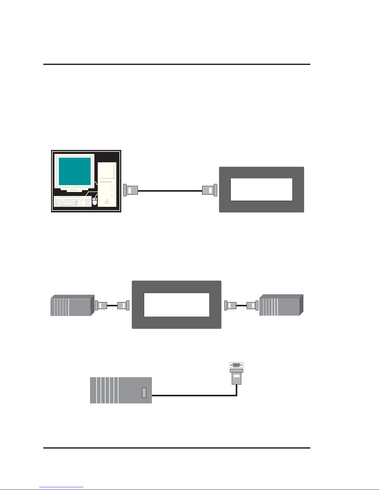
Configuration of NTXS:
Each NTXS unit has to be configured using the NTXS Software before connecting it to the PLC.
NTXS-IBM
Normal Operation:
After configuration is completed, NTXS should be connected with a PLC to start the system.
PLC
To PLC
Programming Port
PLC port
of unit
Connecting
Cable
PLC1
PLC2
Page 11
Introduction
5
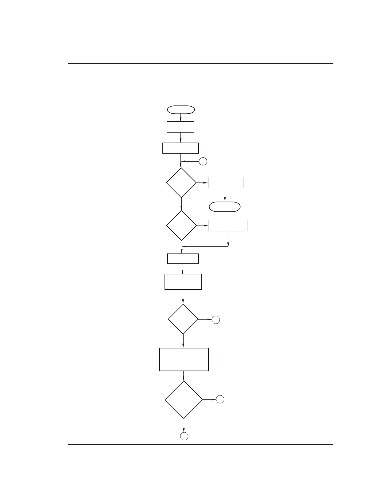
1.3 How NTXS Works
The NTXS follows a specific sequence for performing the tasks defined by the user in the application.
The sequence is as shown below
Power-up
Message
Power up Task
START
IBM
Comm
?
A
Complete IBM
Communication
PLC
Comm
Error
?
Y
N
N
Y
Re-establish PLC
Communication
Re-Start
Global Task
Check Screen
Number
N
Y
Same
Screen
Number
?
C
Perform After Hiding
Task for Previous
Screen
Password
Protected
Screen
?
N
Y
D
B
Page 12
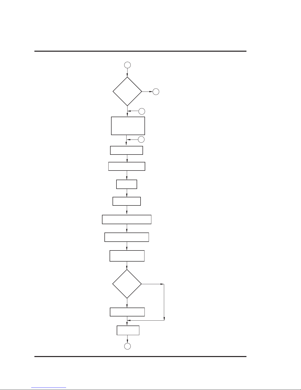
Introduction
6
Check if same key
pressed
Upload Alarm Block
Serv Alarm
Display Screen
Display Associated Screens
Serv While Showing Task
Y
N
Key Release task
Same
key
Pressed
?
Load new
keys
I
Valid
Screen
password
?
N
Y
Perform Before
Showing Task List
for new Screen
F
D
C
Upload Tag Block
B
Page 13
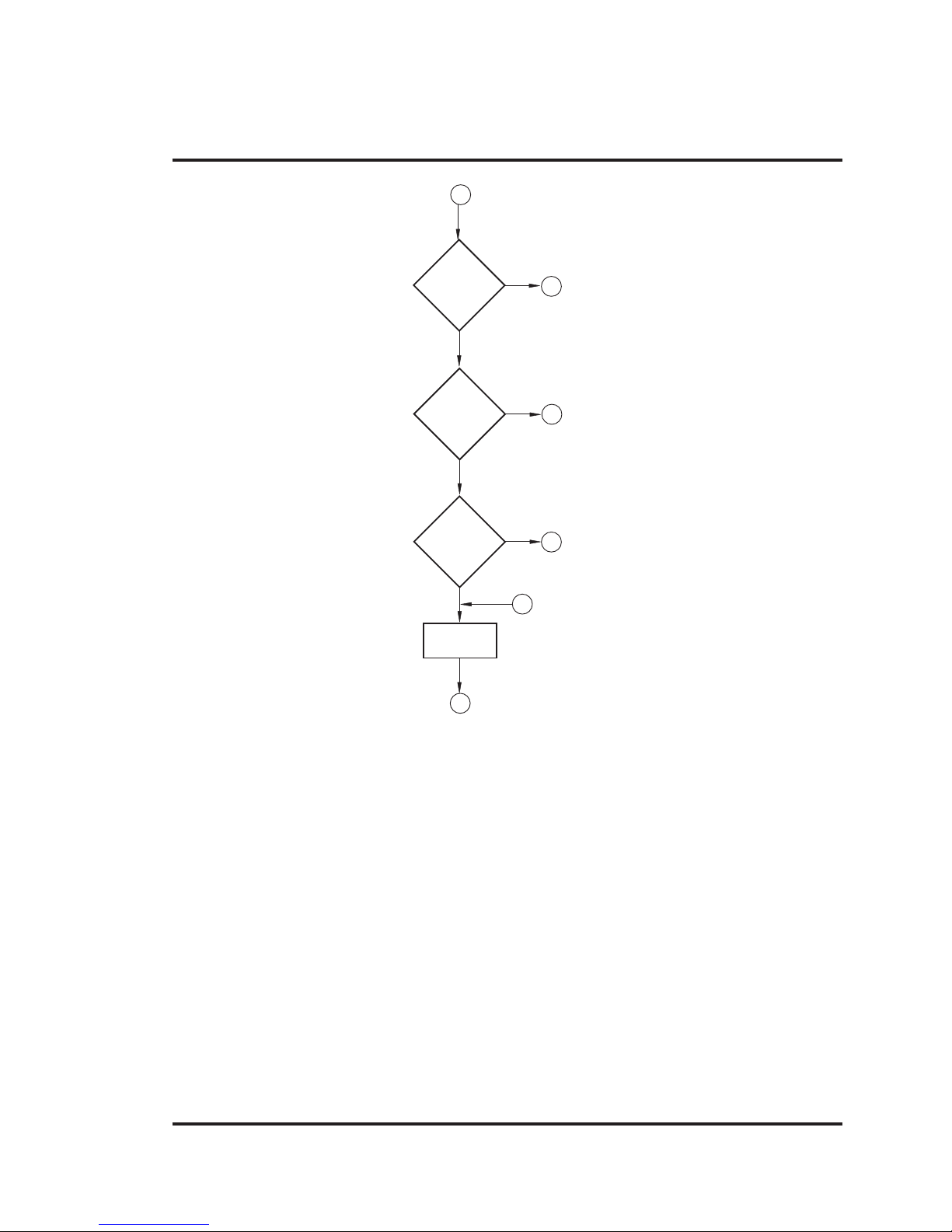
Introduction
7
Y
N
New
key
Pressed
?
A
I
Y
N
Valid Key
Password
?
A
Serv Key
Press Task
Password
Protected
Key ?
Y
G
N
G
A
Page 14

Introduction
8
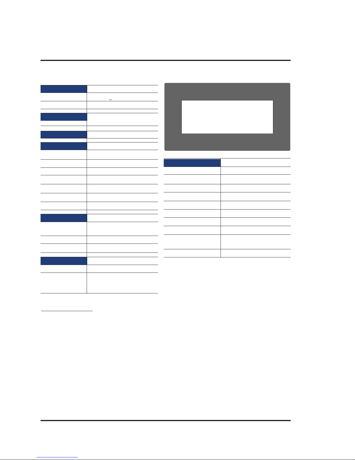
1.3.1 Specifications of NTXS Series
Models included in the NTXS series are as follows:
NT2S-SF121B-EV2
NT2S-SF122B-EV2
NT2S-SF123B-EV2
NT2S-SF125B-E
NT2S-SF126B-E
NT2S-SF127B-E
NT3S-ST121B-E
NT3S-ST123B-E
NT3S-ST124B-E
NT3S-ST126B-E
Page 15
Introduction
9
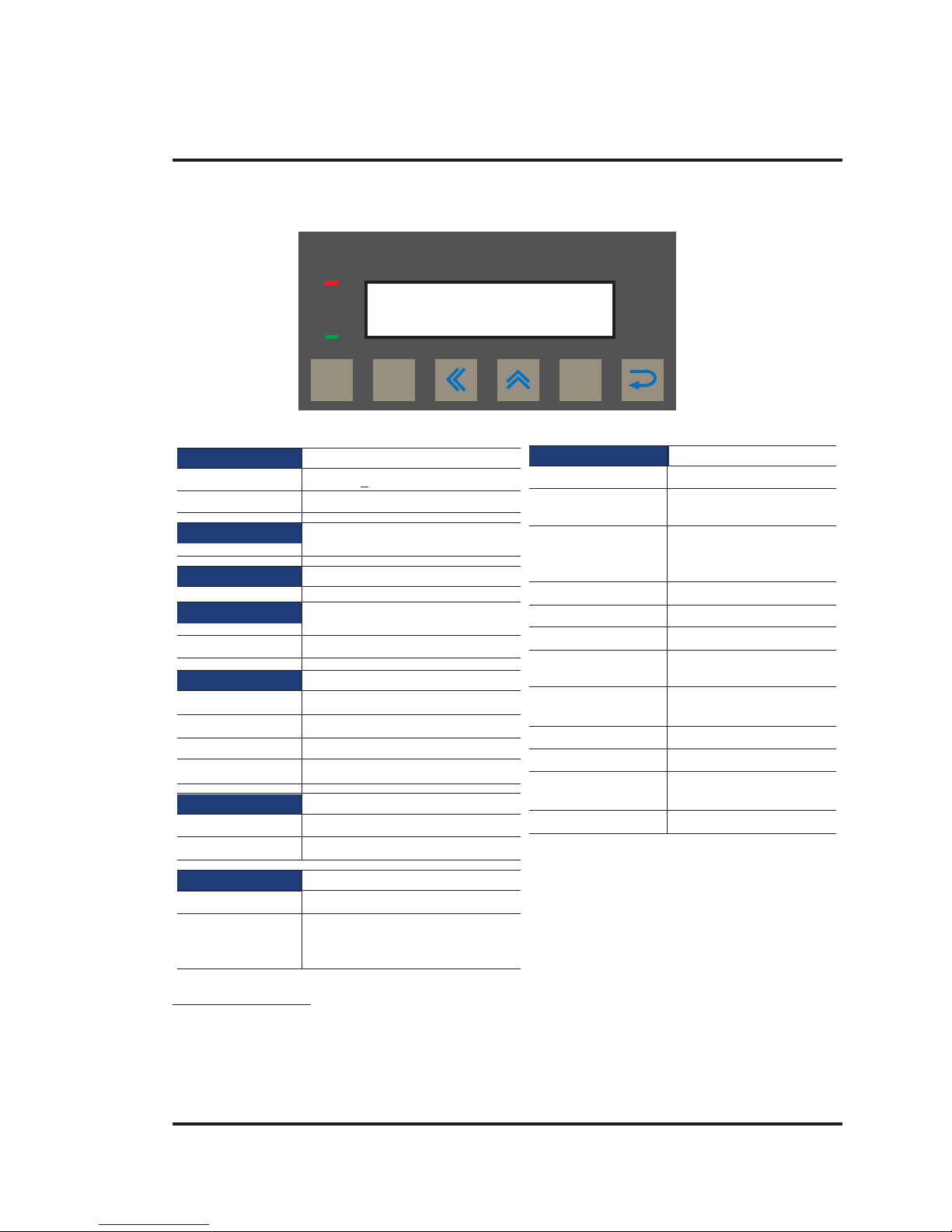
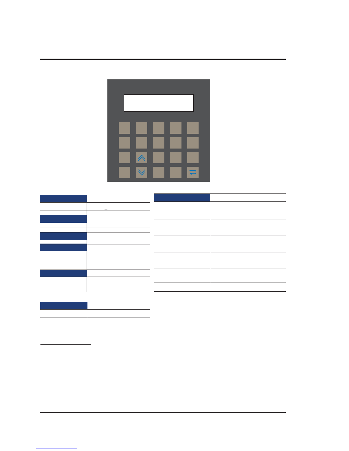
NT2S-SF121B-EV2
System Components:
- Unit with LCD display , Membrane keypad and R TC.
- Power Supply connector.
- Installation Kit: Gasket, Two Mounting clamps
Note: User should order cables separately
Power Supply 24VDC
Voltage Rating 24 VDC
+ 10%
Power Rating 1.5W
Approvals CE, CSA and cULus Class 1
Div.2 Certified
Bezel IP65 Rated Keypad
Keypad Membrane Keypad With Tactile
Feedback Keys
Number Of Keys 6 user Definable keys
Memory
Total Memory 63KB
Application Memory 24KB
Data Register 1000
Retentive Register 1000
Display LCD Text Display
Display Type 2 lines of 16 characters Backlit LCD
LEDs 2 LEDs
Communication
Number of Ports 2
Type One RS232/CMOS port for
connecting to PLC and one RS232
port for programming and printing
PREV CLR
F 1F 2F 3F 4F 5
F 6
NEXT
Miscellaneous
Dimension 92.00 X 45.00 mm
Battery Coin Type, 3V Lithium
Battery 614-CR1225FH
Battery Backup 8 years typical battery
backup for RTC and
System data
Operating Temperature 0
0
C to 50 0C
Storage Temperature -25
0
C to 80 0C
Mounting Method Panel Mounting
Clock(RTC) Real Time Clock
Function(Date & Time)
Humidity 10% To 90%
(Noncondensing)
Immunity to ESD Level 3 as per IEC1000-4-2
Immunity to Transients Level 3 as per IEC1000-4-4
Immunity to Radiated Level 3 as per IEC1000-4-3
RF
Emission EN55011 CISPRA
Page 16

Introduction
10
NT2S-SF122B-EV2
System Components:
- Unit with LCD display , Membrane keypa d
- Installation Kit: Gasket, Two Mounting clamps
Note: User should order cables separately
Power Supply 5VDC
Voltage Rating 5 VDC
+ 10% from PLC
Approvals CE, CSA and cULus Class 1
Div.2 Certified
Bezel IP65 Rated Keypad
Keypad Membrane Keypad With Tactile
Feedback Keys
Number Of Keys 6 user Definable keys
Memory
Total Memory 63KB
Application Memory 24KB
Data Register 1000
Retentive Register 1000
Display LCD Text Display
Display Type 2 lines of 16 characters
Backlit LCD
LEDs 2 LEDs
Communication
Number of Ports 2
Type One RS232/CMOS port for
connecting to PLC and one RS232
port for programming and printing
PREV CLR
F 1F 2F 3F 4F 5
F 6
NEXT
Miscellaneous
Dimension 92.00 X 45.00 mm
Operating Temperature 0
0
C to 50 0C
Storage Temperature -25
0
C to 80 0C
Mounting Method Panel Mounting
Humidity 10% To 90%
(Noncondensing)
Immunity to ESD Level 3 as per IEC1000-4-2
Immunity to Transients Level 3 as per IEC1000-4-4
Immunity to Radiated Level 3 as per IEC1000-4-3
RF
Emission EN55011 CISPRA
Page 17
Introduction
11
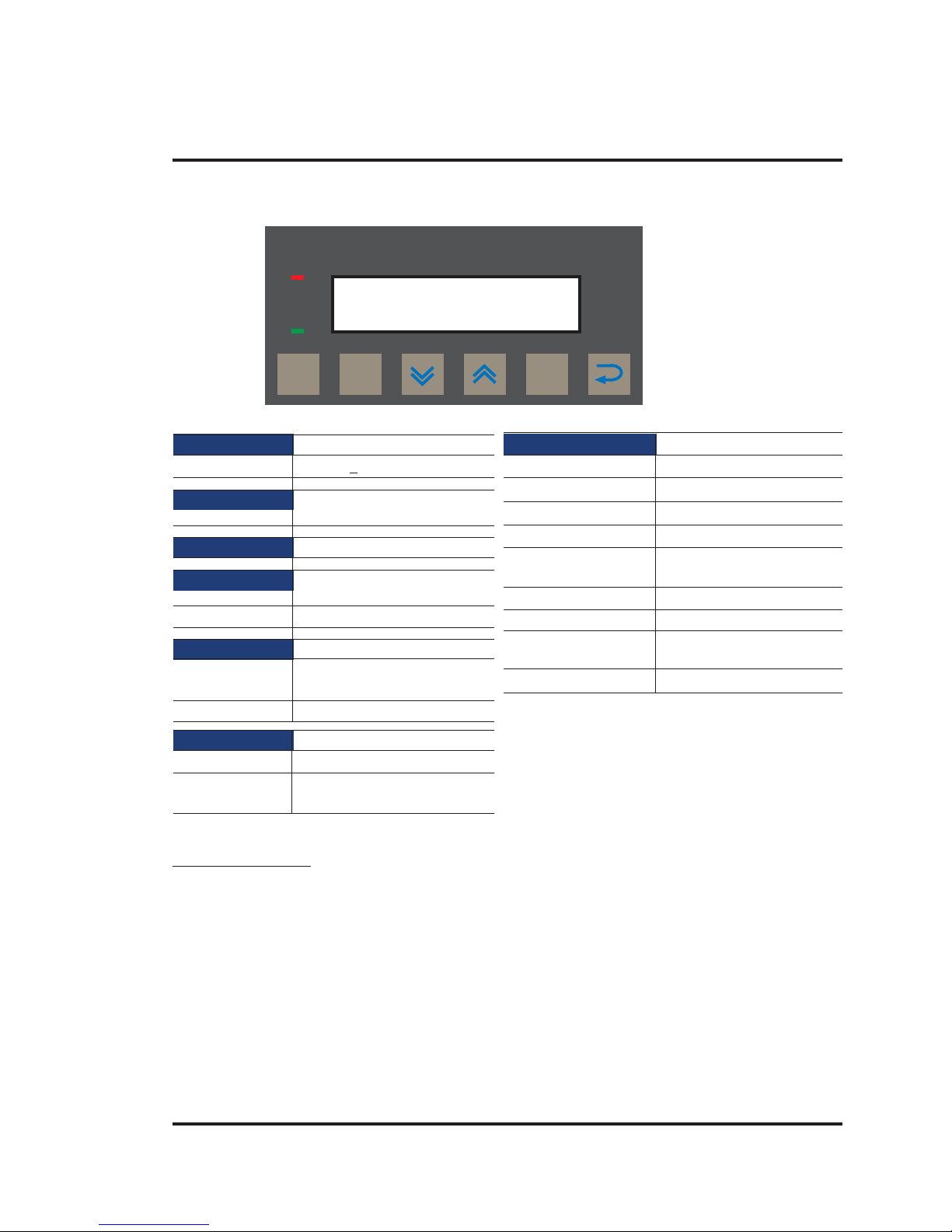
NT2S-SF123B-EV2
System Components:
- Unit with LCD display , Membrane keypa d
- Installation Kit: Gasket, Two Mounting clamps
Note: User should order cables separately
Power Supply 5VDC
Voltage Rating 5 VDC
+ 10% from PLC
Approvals CE, CSA and cULus Class 1
Div.2 Certified
Bezel IP65 Rated Keypad
Keypad Membrane Keypad With Tactile
Feedback Keys
Number Of Keys 6 keys
Display LCD Text Display
Display Type 2 lines of 16 characters
Backlit LCD
LEDs 2 LEDs
Communication
Number of Ports 1
Type CMOS port for communication
to PLC
DATA CLR
F 1
F 2F 3F 4F 5
F 6
REG
Miscellaneous
Dimension 92.00 X 45.00 mm
Operating Temperature 0
0
C to 50 0C
Storage Temperature -25
0
C to 80 0C
Mounting Method Panel Mounting
Humidity 10% To 90%
(Noncondensing)
Immunity to ESD Level 3 as per IEC1000-4-2
Immunity to Transients Level 3 as per IEC1000-4-4
Immunity to Radiated Level 3 as per IEC1000-4-3
RF
Emission EN55011 CISPRA
Page 18
Introduction
12
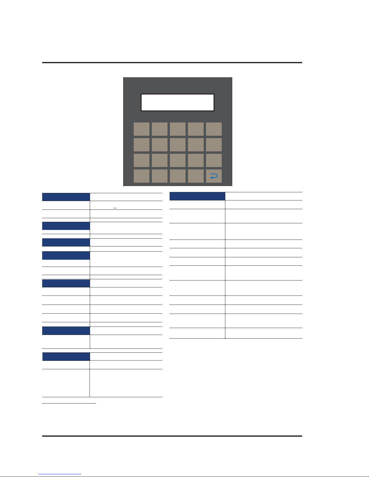
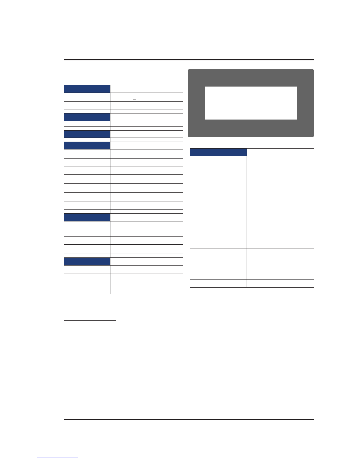
NT2S-SF125B-E
System Components:
- Unit with LCD display , Membrane keypad and R TC.
- Power Supply connector.
- Installation Kit: Gasket, T wo Mounting clamp s
Note: User should order cables separately
Communication
Number of Ports 2
Type One RS232/CMOS port for
connecting to PLC and one
RS232 port for Programming
and Printing
Power Supply 24VDC
Voltage Rating 24 VDC
+ 10%
Power Rating 1.5W
Approvals CE and cULus Class1 Div. 2
Certified
Bezel IP65 Rated Keypad
Keypad PCB based Keypad With
Tactile Feedback Keys
Number Of Keys 20 keys
Memory
Total Memory 63KB
Application Memory 24KB
Data Register 1000
Retentive Register 1000
Display LCD Text Display
Display Type 2 lines of 16 characters
Backlit LCD
1
4
7
CLR
2
5
8
0
3
6
9
+/-
F1
F2
F3
F4
F5
F6
F7
F8
Miscellaneous
Dimension 92.00 X 92.00 mm
Battery Coin Type, 3V Lithium Battery
614-CR1225FH
Battery Backup 8 years typical battery backup
for RTC and System data
Operating Temperature 0
0
C to 50 0C
Storage Temperature -25
0
C to 80 0C
Mounting Method Panel Mounting
Clock(RTC) Real Time Clock Function
(Date & Time)
Humidity 10% To 90%
(Noncondensing)
Immunity to ESD Level 3 as per IEC1000-4-2
Immunity to Transients Level 3 as per IEC1000-4-4
Immunity to Radiated Level 3 as per IEC1000-4-3
RF
Emission EN55011 CISPRA
Page 19
Introduction
13
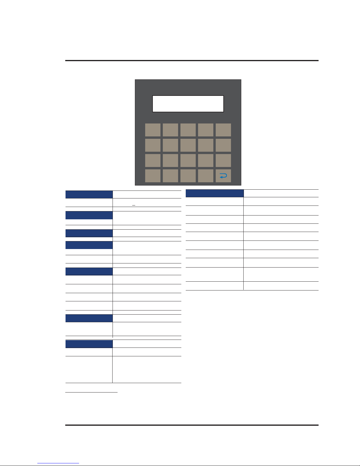
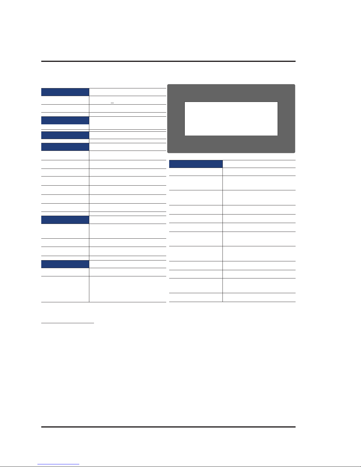
NT2S-SF126B-E
System Components:
- Unit with LCD display , Membrane keypa d
- Installation Kit: Gasket, Two Mounting clamps
Note: User should order cables separately
Communication
Number of Ports 2
Type One RS232/CMOS port for
connecting to PLC and one
RS232 port for Programming
and Printing
Power Supply 5VDC
Voltage Rating 5 VDC
+ 10% from PLC
Approvals CE and cULus Class1 Div. 2
Certified
Bezel IP65 Rated Keypad
Keypad PCB based Keypad With
Tactile Feedback Keys
Number Of Keys 20 User definable keys
Memory
Total Memory 63KB
Application Memory 24KB
Data Register 1000
Retentive Register 1000
Display LCD Text Display
Display Type 2 lines of 16 characters
Backlit LCD
1
4
7
CLR
2
5
8
0
3
6
9
+/-
F1
F2
F3
F4
F5
F6
F7
F8
Miscellaneous
Dimension 92.00 X 92.00 mm
Operating Temperature 0
0
C to 50 0C
Storage Temperature -25
0
C to 80 0C
Mounting Method Panel Mounting
Clock(RTC) Does not support RTC
Humidity 10% To 90% (Noncondensing)
Immunity to ESD Level 3 as per IEC1000-4-2
Immunity to Transients Level 3 as per IEC1000-4-4
Immunity to Radiated Level 3 as per IEC1000-4-3
RF
Emission EN55011 CISPRA
Page 20
Introduction
14
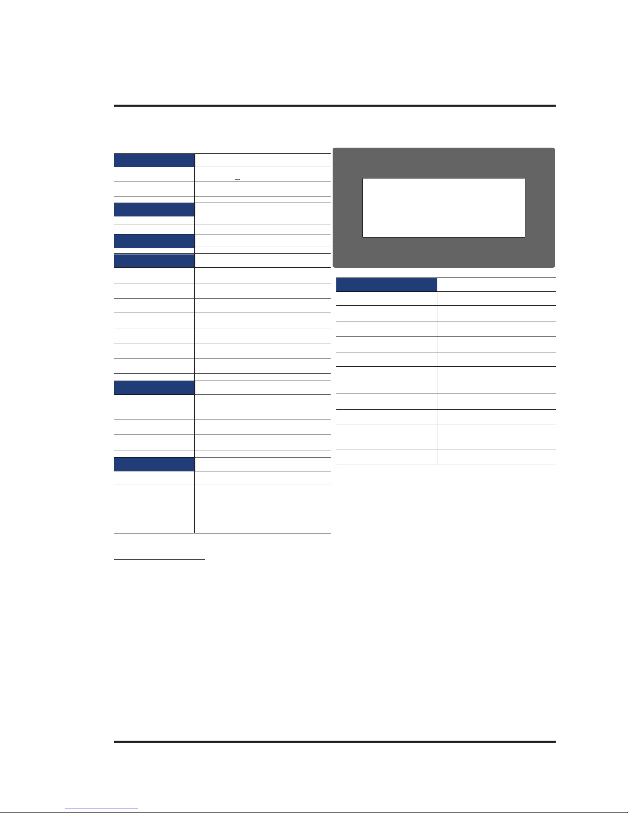
NT2S-SF127B-E
System Components:
- Unit with LCD display , Membrane keypa d
- Installation Kit: Gasket, Two Mounting clamps
Note: User should order cables separately
Power Supply 5VDC
Voltage Rating 5 VDC
+ 10% from PLC
Approvals CE and cULus Class1 Div.2
Certified
Bezel IP65 Rated Keypad
Keypad PCB based Keypad With
Tactile Feedback Keys
Number Of Keys 20 keys
Display LCD Text Display
Display Type 2 lines of 16 characters
Backlit LCD
Communication
Number of Ports 1
Type CMOS port for connecting
to PLC
1
4
7
CLR
2
5
8
0
3
6
9
+/-
F1
F2
F3
F4
REG
DATA
Miscellaneous
Dimension 92.00 X 92.00 mm
Operating Temperature 0
0
C to 50 0C
Storage Temperature -25
0
C to 80 0C
Mounting Method Panel Mounting
Clock(RTC) Does not support RTC
Humidity 10% To 90% (Noncondensing)
Immunity to ESD Level 3 as per IEC1000-4-2
Immunity to Transients Level 3 as per IEC1000-4-4
Immunity to Radiated Level 3 as per IEC1000-4-3
RF
Emission EN55011 CISPRA
Page 21
Introduction
15
NT3S-ST121B-E
Miscellaneous
Dimension 132.00 X 69.00 mm
Battery Coin Type, 3V Lithium
Battery 614-CR1225FH
Battery Backup 8 years typical battery backup
for RTC and System data
Operating Temperature 0
0
C to 50 0C
Storage Temperature -25
0
C to 80 0C
Mounting Method Panel Mounting
Clock(RTC) Real Time Clock Function
(Date & Time)
Humidity 10% To 90%
(Noncondensing)
Immunity to ESD Level 3 as per IEC1000-4-2
Immunity to Transients Level 3 as per IEC1000-4-4
Immunity to Radiated Level 3 as per IEC1000-4-3
RF
Emission EN55011 CISPRA
System Components:
- Unit with LCD display , touch screen and R TC
- Power Supply connector.
- Installation Kit: Gasket, Two Mounting clamps
Note: User should order cables separately
Power Supply 24VDC
Voltage Rating 24 VDC
+ 10%
Power Rating 3.5W
Approvals CE and cULus Class 1 Div.
2 Certified
Bezel IP65 Rated
Memory
Total Memory 512KB
Application Memory 120KB
Data Register 1000
Retentive Register 1000
System Register 64
System Coil 100
Internal Coil 5000
Display LCD Graphic Display
Display Type Monochrome Backlit
LCD Display
Display Resolution 192 X 64 Pixels
Touch Screen 4 wire, Analog Resistive
Communication
Number of Ports 2
Type RS232/CMOS/RS485/RS422
for connecting to PLC,
Programming and Printing
Page 22
Introduction
16
NT3S-ST123B-E
System Components:
- Unit with LCD display , touch screen and R TC
- Power Supply connector.
- Installation Kit: Gasket, T wo Mounting clamp s
Note: User should order cables separately
Miscellaneous
Dimension 132.00 X 69.00 mm
Battery Coin Type, 3V Lithium
Battery 614-CR1225FH
Battery Backup 8 years typical battery backup
for RTC and System data
Operating Temperature 0
0
C to 50 0C
Storage Temperature -25
0
C to 80 0C
Mounting Method Panel Mounting
Clock(RTC) Real Time Clock Function
(Date & Time)
Humidity 10% To 90%
(Noncondensing)
Immunity to ESD Level 3 as per IEC1000-4-2
Immunity to Transients Level 3 as per IEC1000-4-4
Immunity to Radiated Level 3 as per IEC1000-4-3
RF
Emission EN55011 CISPRA
Power Supply 24VDC
Voltage Rating 24 VDC
+ 10%
Power Rating 3.5W
Approvals CE and cULus Class 1
Div. 2 Certified
Bezel IP65 Rated
Memory
Total Memory 512KB
Application Memory 120KB
Data Register 1000
Retentive Register 1000
System Register 64
System Coil 100
Internal Coil 5000
Display LCD Graphic Display
Display Type Monochrome Backlit
LCD Display
Display Resolution 192 X 64 Pixels
Touch Screen 4 wire, Analog Resistive
Communication
Number of Ports 2
Type One RS232/CMOS/RS485/RS422
and one RS232/CMOS for
connecting to PLC, Programming
and Printing
Page 23
Introduction
17
NT3S-ST124B-E
Miscellaneous
Dimension 132.00 X 69.00 mm
Operating Temperature 0
0
C to 50 0C
Storage Temperature -25
0
C to 80 0C
Mounting Method Panel Mounting
Clock(RTC) Does not support RTC
Humidity 10% To 90%
(Noncondensing)
Immunity to ESD Level 3 as per IEC1000-4-2
Immunity to Transients Level 3 as per IEC1000-4-4
Immunity to Radiated Level 3 as per IEC1000-4-3
RF
Emission EN55011 CISPRA
Power Supply 24VDC
Voltage Rating 24 VDC
+ 10%
Power Rating 3.5W
Approvals CE and cULus Class 1
Div. 2 Certified
Bezel IP65 Rated
Memory
Total Memory 512KB
Application Memory 120KB
Data Register 1000
Retentive Register 1000
System Register 64
System Coil 100
Internal Coil 5000
Display LCD Graphic Display
Display Type Monochrome Backlit
LCD Display
Display Resolution 192 X 64 Pixels
Touch Screen 4 wire, Analog Resistive
Communication
Number of Ports 2
Type One RS232/CMOS/RS485/RS422
and One RS232/CMOS port for
connecting to PLC, Programming
and Printing
System Components:
- Unit with LCD display , touch screen
- Power Supply connector.
- Installation Kit: Gasket, Two Mounting clamps
Note: User should order cables separately
Page 24
Introduction
18
NT3S-ST126B-E
Miscellaneous
Dimension 132.00 X 69.00 mm
Operating Temperature 0
0
C to 50 0C
Storage Temperature -25
0
C to 80 0C
Mounting Method Panel Mounting
Clock(RTC) Does not support RTC
Humidity 10% To 90% (Noncondensing)
Immunity to ESD Level 3 as per IEC1000-4-2
Immunity to Transients Level 3 as per IEC1000-4-4
Immunity to Radiated Level 3 as per IEC1000-4-3
RF
Emission EN55011 CISPRA
System Components:
- Unit with LCD display , touch screen
- Power Supply connector.
- Installation Kit: Gasket, T wo Mounting clamp s
Note: User should order cables separately
Power Supply 24VDC
Voltage Rating 24 VDC
+ 10%
Power Rating 3.5W
Approvals CE and cULus Class 1
Div. 2 Certified
Bezel IP65 Rated
Memory
Total Memory 512KB
Application Memory 120KB
Data Register 1000
Retentive Register 1000
System Register 64
System Coil 100
Internal Coil 5000
Display LCD Graphic Display
Display Type Monochrome Backlit
LCD Display
Display Resolution 192 X 64 Pixels
Touch Screen 4 wire, Analog Resistive
Communication
Number of Ports 2
Type RS232/CMOS for connecting
to PLC, Programming and
Printing
Page 25

Hardware
19
HARDW ARE
In this chapter. . . .
♦ Safety Precautions
♦ Installation Instructions
♦ Power Requirements
♦ Wiring Diagram
♦ Communication Ports
Page 26

Hardware
20
2.1 Safety Precaution
Please observe the following precautions when installing the unit. Failure to comply with these restrictions could result in loss of life, serious personal injury , or equipment damage.
Warning: Do not operate the HMI in areas subject to explosion due to flammable
gases, vapors, or dusts.
Warning: Do not connect the HMI to an AC power source. Y ou will cause permanent
damage to the HMI.
Warning: Do not attempt to use a DC power supply that does not meet HMI power
requirements. You may cause malfunction or permanent damage to HMI.
Warning: Do not power the HMI with a DC power supply used for inductive loads or for
input circuitry to the programmable logic controller. Severe volt age spikes
caused by these devices may damage the HMI.
2.2 Installation Instructions
The NTXS should be mounted on a panel. Gasket, mounting clamps are provided with each NTXS unit
for proper mounting.
Environmental Considerations:
Make sure that the unit is installed correctly and that the operating limits are followed (see S pecifications
for NTXS).
Do not operate NTXS in areas subject to explosion hazards due to flammable gases, vapors or dusts.
NTXS should not be installed where fast temperature variations are present. Highly humid areas are
also to be avoided. High humidity causes condensation of water in the unit.
Location Considerations:
Care should be taken when locating equipment behind the NTXS to ensure that AC power wiring, PLC
output modules, contactors, starters, relays and any other source of electrical interference are located
away from NTXS. Particular care should be taken to the position of V ariable speed drives and switching
power supplies away from the NTXS.
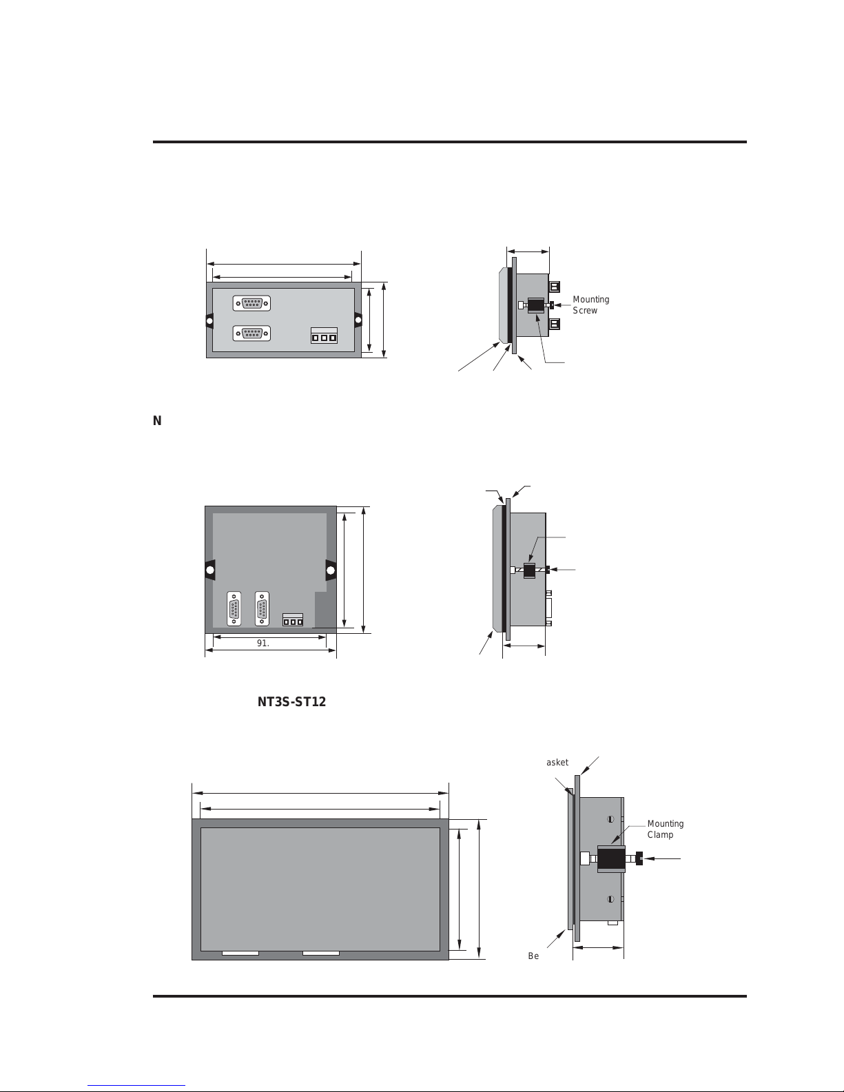
Panel Mounting
This section presents the dimensional sketches and panel cutouts for NTXS models.
(All dimensions are in mm. Not to Scale.)
!
!
!
!
Page 27
Hardware
21
NT2S-SF121B-EV2, NT2S-SF122B-EV2 and NT2S-SF123B-EV2
Panel cutout: 92.00 mm x 45.00 mm
All Dimensions are in mm.
108.30
91.20
44.18
60.50
Panel
Gasket
Bezel
Clamp
27.10
Mounting
Screw
NT2S-SF125B-E, NT2S-SF126B-E and NT2S-SF127B-E
Panel Cutout: 92.00 mm x 92.00 mm
All Dimensions are in mm.
2-4
106.88
91.30
91.30
106.88
Panel
25.80
Gasket
Mounting
Screw
Clamp
Bezel
12345
12345
NT3S-ST121B-E, NT3S-ST123B-E, NT3S-ST124B-E and NT3S-ST126B-E
Panel cutout: 132.00 mm x 69.00 mm
All Dimensions are in mm.
131.00
140.00
68.00
77.20
1234567890
1234567890
31.80
Mounting
Screw
Panel
Gasket
Mounting
Clamp
Bezel
Page 28

Hardware
22
2.3 Power Requirements
Supply voltage requirements for NTXS series models is as follows:
NT2S-SF121B-EV2 +24VDC + 10%, 1.5W maximum on Power Port
NT2S-SF122B-EV2 +5VDC + 10% on PLC port
NT2S-SF123B-EV2 +5VDC + 10% on PLC port
NT2S-SF125B-E +24VDC + 10%, 1.5W maximum on Power Port
NT2S-SF126B-E +5VDC + 10% on PLC port
NT2S-SF127B-E +5VDC + 10% on PLC port
NT3S-ST121B-E +24VDC + 10%, 3.5W maximum on Power Port
NT3S-ST123B-E +24VDC + 10%, 3.5W maximum on Power Port
NT3S-ST124B-E +24VDC + 10%, 3.5W maximum on Power Port
NT3S-ST126B-E +24VDC + 10%, 3.5W maximum on Power Port
Please follow the instructions given below while making power supply connections for models:
1. Follow the wiring diagram on the sticker of the unit which shows terminals.
2. To make a connection strip about 7mm of insulation of the wire, turn the connector screw
counter-clock wise until the gap is wide open. Insert the wire all the way in and turn the screw
clockwise until it is tight.
3. Wire lengths should be minimum. Wires should run in pairs with a neutral or common paired
with a live or signal wire.
4. NTXS +24VDC model is fused internally with a self resetting 60V , 400mA fuse. It is recom
mended that all input power lines be protected from product failure by a fuse or breaker.
5. Adequate strain relief must be provided for the power connector, to ensure that vibration does
not cause the power connector to be pulled out.
6. All the NTXS products are housed in a moulded ABS plastic case which eliminates any
electrical shock hazard. Hence Safety Earth is not required to be connected to the chassis of
the unit.
7. The DC ground is not directly coupled to Earth ground internally. The unit is designed to
operate properly whether or not the DC ground is connected to the Earth ground. We do recom
mend, however, that if the DC ground has to be connected to the Earth ground, the Earth
connection should be made to a central star point as poor site earths can introduce noise into a
system.
8. Do not power unit and inductive loads with the same power supply even though there is
enough immunity in the NTXS to withstand the transients present on these lines. A void using
power supplies with large capacitive outputs which may cause problems if power is cycled within
a short time period.
9. If wiring is to be exposed to lightening or surges, use appropriate surge suppression devices.
10. Keep AC, high energy and rapidly switching DC wiring sep arate from signal wires.
1 1. Connecting high voltages or AC power mains to the DC input will make unit unusable and
may create an electrical shock hazard to personnel. Such a failure or shock could result in
serious personal injury , loss of life and/or equipment damage. DC voltage sources should
provide proper isolation from main AC power and similar hazards.
Page 29
Hardware
23
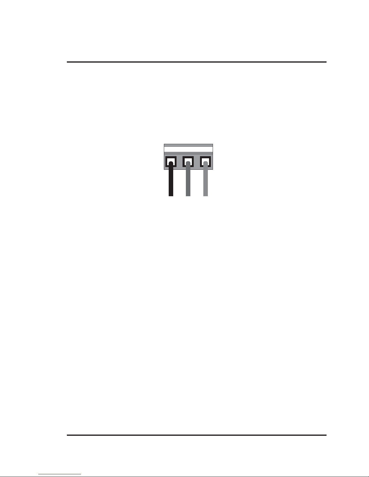
2.4 Wiring Diagram
If wiring is to be exposed to lightening or surges, use appropriate surge suppression devices. Keep AC,
high energy and rapidly switching DC wiring separate from signal wires.
Connecting high voltages or AC power mains to the DC input will make unit unusable and may create an
electrical shock hazard to personnel. Such a failure or shock could result in serious personal injury , loss
of life and/or equipment damage. DC voltage sources should provide proper isolation from main AC
power and similar hazards.
Pin description of the power connector for NTXS Models is as follows:
DC+ DC- Earth
24Vdc
123
2.5 Communication Ports
NTXS unit has 2 types of communication ports.
One port of NT2S models has RS232/CMOS signals. This port is used to connect to PLC. The other
port has RS232 signals which is used for receiving configuration setup and printing.
Note: NT2S-SF123B-EV2 and NT2S-SF127B-E units have only a PLC port with CMOS signals.
NT3S has multi-signal ports meaning RS232/RS485/CMOS signal level ports.
Note: NT3S-ST126B-E unit has only RS232 and CMOS signal level ports.
NT3S units can simultaneously communicate with two devices on these serial ports. Units can receive
data from PC on either of the ports. Both the ports are also capable of Serial Printing. Each port has to
be configured for their function. Even if both the ports are configured for PLC connection, user can
download data from NTXS software on either of the ports. For Programming cable details, please refer
to Appendix.
Different cables are required for different devices. Cable details for any p articular device are given in the
Operation Manual of that device. Pin description of the communication Ports for NT2S and NT3S
models is as given in following pages.
Page 30

Hardware
24
NT3S-ST121B-E
Com1 and Com2 Ports
Port Type: DB9 Female
Pin Name Description
Number
1 TX+ Transmit +
2 232TXD Transmit 232
3 RXD Receive 232 / CMOS
4 RX+ Receive +
5 GND Circuit Ground
6 VCC +5 VDC
7 CMOSTXD Transmit CMOS
8 TX- Transmit 9 RX- Receive -
NT3S-ST123B-E / NT3S-ST124B-E
Com1 Port
Port Type: DB9 Female
Pin Name Description
Number
1 TX+ Transmit +
2 232TXD Transmit 232
3 RXD Receive 232 / CMOS
4 RX+ Receive +
5 GND Circuit Ground
6 VCC +5 VDC
7 CMOSTXD Transmit CMOS
8 TX- Transmit 9 RX- Receive -
Page 31

Hardware
25
NT3S-ST123B-E / ST124B-E
Com2 Port
Port Type: DB9 Female
Pin Name Description
Number
1NCNC
2 232TXD Transmit 232
3 RXD Receive 232 / CMOS
4NCNC
5 GND Circuit Ground
6 VCC +5 VDC
7 CMOSTXD Transmit CMOS
8NCNC
9NCNC
NT3S-ST126B-E
Com1 and Com2 Ports
Port Type: DB9 Female
Pin Name Description
Number
1NCNC
2 232TXD Transmit 232
3 RXD Receive 232 / CMOS
4NCNC
5 GND Circuit Ground
6 VCC +5 VDC
7 CMOSTXD Transmit CMOS
8NCNC
9NCNC
Page 32

Hardware
26
NT2S-SF121B-EV2 / SF125B-E
Com1 Port (PLC Port)
Port Type: DB9 Female
Pin Name Description
Number
1 GND Circiut Ground
2 232TXD Transmit 232
3 RXD Receive 232 / CMOS
4 GND Circuit Ground
5 GND Circuit Ground
6 VCC +5 VDC
7 CMOSTXD Transmit CMOS
8 DIR Direction Control
9 PLC ATTACH Attach PLC. Should be grounded inside the cable
NT2S-SF122B-EV2 / SF126B-E
Com1 Port (PLC Port)
Port Type: DB9 Male
Pin Name Description
Number
1NCNC
2 DIR Direction Control
3 232TXD Transmit 232
4 VCC +5 VDC
5 GND Circuit Ground
6 CMOSTXD Transmit CMOS
7 RXD Receive 232 / CMOS
8 RXD Receive 232 / CMOS
9NCNC
Page 33

Hardware
27
NT2S-SF121B-EV2 / SF122B-EV2 / SF125B-E / SF126B-E
Com2 Port (Serial Port)
Port Type: DB9 Female
Pin Name Description
Number
1NCNC
2 TXD Transmit RS232
3 RXD Receive RS232
4NCNC
5NCNC
6NCNC
7NCNC
8NCNC
9 GND Circuit Ground
NT2S-SF123B-EV2 / SF127B-E
Com1 Port (PLC Port)
Port Type: DB9 Male
Pin Name Description
Number
1NCNC
2NCNC
3NCNC
4 VCC +5 VDC
5 GND Circuit Ground
6 CMOS TXD Transmit CMOS
7 RXD Receive CMOS
8 RXD Receive CMOS
9NCNC
Page 34

Hardware
28
NT2S-SF121B-EV2 / SF125B-E
Com1 Port (PLC Port)
Port Type: DB9 Female
Pin Name Description
Number
1 GND Circiut Ground
2 232TXD Transmit 232
3 RXD Receive 232 / CMOS
4 GND Circuit Ground
5 GND Circuit Ground
6 VCC +5 VDC
7 CMOSTXD Transmit CMOS
8 DIR Direction Control
9 PLC ATTACH Attach PLC. Should be grounded inside the cable
NT2S-SF122B-EV2 / SF126B-E
Com1 Port (PLC Port)
Port Type: DB9 Male
Pin Name Description
Number
1NCNC
2 DIR Direction Control
3 232TXD Transmit 232
4 VCC +5 VDC
5 GND Circuit Ground
6 CMOSTXD Transmit CMOS
7 RXD Receive 232 / CMOS
8 RXD Receive 232 / CMOS
9NCNC
Page 35

Hardware
29
NT2S-SF121B-EV2 / SF122B-EV2 / SF125B-E / SF126B-E
Com2 Port (Serial Port)
Port Type: DB9 Female
Pin Name Description
Number
1NCNC
2 TXD Transmit RS232
3 RXD Receive RS232
4NCNC
5NCNC
6NCNC
7NCNC
8NCNC
9 GND Circuit Ground
NT2S-SF123B-EV2 / SF127B-E
Com1 Port (PLC Port)
Port Type: DB9 Male
Pin Name Description
Number
1NCNC
2NCNC
3NCNC
4 VCC +5 VDC
5 GND Circuit Ground
6 CMOS TXD Transmit CMOS
7 RXD Receive CMOS
8 RXD Receive CMOS
9NCNC
Page 36

Before you Begin
30
BEFORE YOU BEGIN
In this chapter. . . .
♦ Connecting the HMI to a Computer
♦ Starting NTXS Software
♦ Setting Network Configuration
Page 37

Before you Begin
31
3.1 Connecting the HMI to your Computer
Before you start your first project, the HMI should be connected to the computer so that the project can
be downloaded after creating it. You should also connect the PLC that you are using with the HMI so that
you can test the operation of the HMI after you have finished creating the sample project.
• To connect your HMI to the computer
1. Connect a +24VDC power supply to the HMI.
2. Connect the programming cable to the computer and HMI.
• Connect IBM cable to the communication port of NTXS.
• Download Firmware i.e. driver for the PLC. The NTXS unit cannot communicate with
PLC till the required driver is downloaded.
3. Apply power to the HMI.
• To connect your PLC to HMI
NTXS can communicate with any PLC without any change in the NTXS hardware. To communi
-cate with a PLC, NTXS unit needs:
1. Proper Communication Driver for the PLC
2. NTXS - PLC communication cable
1. Communication Driver for the PLC:
Each PLC has a defined protocol for communicating with any device. Communication Driver is
downloaded into NTXS unit along with the firmware. Communication driver varies from PLC to
PLC. This driver enables unit to talk to a specific PLC, such as OMRON PLC.
2. NTXS:
PLC Communication Cable: Proper NTXS - PLC cable is required for error free communication
with a PLC.
Page 38

Before you Begin
32
3.2 Starting NTXS Software
3.2.1 Installing NTXS Software
System requirements for installing NTXS on your PC:
Windows Version : Microsoft Windows® 2000 or higher
Processor : 266 MHz Pentium® II or higher
Pentium-compatible CPU
Hard disk Space : 150 MB free memory space
Serial Mouse : Microsoft® mouse or compatible pointing
device
RAM : At least 64 megabytes (MB) of RAM; more
memory generally improves responsiveness
Display resolution : 800x600 with 24 bit true color
Serial Port : One Serial Port for Downloading Required
To install NTXS Software:
1. Open Microsoft Windows.
2. Select Run and Pop up window appears. Type the p ath for inst alling the Setup.
This will install NTXS Setup Software.
3. When you click on OK, Welcome window appears on the screen. Click on Next.
4. Enter User name and Company name.
Page 39

Before you Begin
33
5. Select the destination folder where Setup will install the files.
Page 40

Before you Begin
34
3.2.2 Steps for starting NTXS Software
1. In Windows click the Start button.
2. Select Programs.
3. Select NTXS V1.03.
4. Select NTXS V1.03.
5. Select New Application either from Tool station or from File Menu.
6. Select the model and product type that you would like to set by clicking on picture of the product in
the list.
7. Define the Unit Settings and Network Configuration.
8. Next step is to define Tag Database and then define the screens according to your application.
7. Installation starts. A dialog box indicating the status of progress of installation will display.
A screen is displayed to inform you when inst allation is completed.
This procedure installs NTXS Software in Start Menu (in selected folder).
6. Select the Program folder.
Page 41

Before you Begin
35
5. When you click on Yes, it will uninstall NTXS V1.03 from your computer.
If you want to install NTXS V1.03, then you have to follow the steps as explained in section 3.2.1.
3.3 Setting Network Configuration
Unit can communicate with any PLC without any changes in the hardware. To communicate with PLC
unit needs proper communication driver. Each PLC has a defined protocol for communicating with any
device. PLC driver is downloaded into unit alongwith the firmware. This driver enables the unit to talk to
a specific PLC.
Using this configuration screen you can set the node address and node name for each port. For NT2S
units, node
address can be set from 0 to 255 but for NT3S units, the highest node address is 32. You can change
default values generated by editing these two fields. Protocol selection box displays list of all supported
PLCs. By clicking this selection box you can see list of Model Numbers in PLC Model selection Box.
Select PLC Name from PLC selection box and PLC Model name from PLC Model selection box.
PLC specific data button is activated only if selected PLC has Special PLC specific dat a to be set.
3.2.3 Uninstalling NTXS Software
1. In Windows click the St art button.
2. Select Programs.
3. Select NTXS V1.03.
4. Select Uninstall NTXS V1.03.
Following screen will be displayed. The screen will ask you for the confirmation for uninstalling NTXS
V1.03.
Page 42

Before you Begin
36
3.3.1 Setting Network Configuration For NT2S Series Products
Unit can be configured for PLC Communication.
Node Address: User can assign unique node address starting from 0 to 255.
Node Name: User can specify node name, maximum upto 15 characters.
PLC: User can select desired PLC from the list of available PLCs.
PLC Model: User can select model for the desired PLC.
Add a Node: A new node is added in the network.
Delete the Node: The selected node can be deleted from the network.
Page 43

Before you Begin
37
3.3.2 Setting Network Configuration For NT3S Series Products
Unit can communicate with any PLC without any change in hardware. To communicate with PLC unit
needs proper communication driver. Each PLC has a defined protocol for communicating with any
device. PLC driver is downloaded in to unit along with the firmware. This driver enables the unit to talk to
a specific PLC.
Unit can be configured in following ways:
1. For IBM Communication
2. For Serial Printing
3. For PLC Communication
Either of the ports can be configured for the ways mentioned above. Depending on the type of communi-
cation, user may require to define certain parameters.
The following table displays number of nodes connected on Com1 and Com2 with their Node address,
node name, node type (unit / PLC), total number of blocks used in application.
Note: Default Node address for unit is 0 for COM1 and COM2. This address needs to be changed if
settings for PLC address is same as unit address.
Page 44

Before you Begin
38
1. For IBM Communication
This is default communication setting. If user wants IBM communication, no other setting is required. In
this case both communication ports can be used for download / upload purpose.
Page 45

Before you Begin
39
2. For Serial Printing
User can set either of the ports for serial printing. This is done by selecting Protocol as “Serial printer”. In
the above example, user has configured Com1 for serial printing. However, when this port is not being
used for printing, it will be used for IBM Communication.
User has to define parameters for serial printing, by using ‘Comm Settings’ option.
Page 46

Before you Begin
40
Following serial printing parameters can be set-
Baud Rate - Supported Baud rates are 4800, 9600, 19.2K, 38.4K, 57.6K and
1 15.2K.
Parity - Can be None, Even or Odd.
Number of Bits - Can be 7 or 8.
Number of columns - Can be from minimum 1 to maximum 80.
Terminating character - Can be None, CR(Carriage Return), LF(Line Feed) or CR+LF.
Number of characters - Can be from minimum 1 to maximum 256.
to print
Click ‘Ok’ to set printer setting.
3. For PLC Communication
Protocol - User can select desired PLC from the list of available drivers. In the example shown above,
user has selected Omron Host Link at Com1.
Page 47

Before you Begin
41
User can set PLC communication parameters like Baud Rate, Parity , Dat a Bit s and Stop Bits.
Click ‘Ok’ to set parameters.
Model - User can select desired PLC model from the list available. In the example shown
above, user has selected ‘CJ1’ model.
Address - Unique PLC node address ( 0 to 32 ).
Name - User can specify node name, which can be maximum up to 15 characters.
Add a Node - User can add a node in the network.
Change a Node -
User can change PLC or PLC related information. First of all user has to select the
node. Then change the information and finally click the button ‘Change a Node’.
PLC specific data -
If additional information is required for PLC, user can select the node. Then this button
is activated. Now by clicking on this button user can provide the desired information.
Delete node - To delete a node, first of all user has to delete all the tags defined for the node. Then
user has to select the node and click the Delete button.
Omron Frame delay can be set using the screen shown below:
Port Settings -
Page 48

Using NTXS Software
42
USING NTXS SOFTW ARE
In this chapter. . . .
♦ NTXS Menu Structure
♦ Creating New Application
♦ Creating Screens
♦ Data Entry Object
♦ Display Data Object
♦ Global And Power On Tasks
♦ Global Keys
♦ Screen Keys
Page 49

Using NTXS Software
43
4.1 NTXS Menu Structure
From Windows Task Bar, click the Start button and select the NTXS V1.03.
The following Window will appear.
The Program displays a Splash screen on Start-up. This dialog can be closed by pressing any key or just
by clicking mouse or waiting 10 seconds for it to automatically go to the next screen (i.e. Toolstation).
Page 50

Using NTXS Software
44
Menu bar operates like any standard Windows Menu bar . To open a particular Menu click it with the help
of Mouse or use key alongwith ALT key just like any other st andard Windows based software. When no
application is opened above Menu bar will be displayed.
Page 51

Using NTXS Software
45
The Tool-Station consist s of icons. When the mouse point s to any icon, a tool-tip is displayed. Click on
the icon to select the particular menu.
Now we will study the different Menus in the Menu Bar .
4.1.1 File Menu
File Menu handles the File related functions. File Menu consists the functions like New Application,
Close Application, Save Application, Print and Exit NTXS. Using Information option user can set or
change NTXS application information such as application title, user name etc.
New - Creates a new application.
Open - Opens a saved application.
Close - Closes currently opened application.
Save - Saves currently opened application.
Save as - Saves the current application with a different name.
Information - Configure application specific information such as application title, author,
password etc.
Import - All the text data associated with wizards (On / Off text, labels etc.) can be
imported. (Refer to USING LANGUAGES Chapter for more information)
Export - Exports data from NTXS projects and put it into a user specified file.
(Refer to USING LANGUAGES Chapter for more information)
Print - Either prints all the current application information such as Project information,
Unit settings, NTXS nodes, tags, screens, application tasklist, screen tasklist,
alarms or the selected attributes.
Exit - Exits NTXS Software.
Page 52

Using NTXS Software
46
4.1.2 Define Menu
This menu defines the application. In the main window of NTXS Software, bottom line of the icons is
dedicated for this menu.
Unit Settings - Defines Unit settings. Normally there is no need to change these
settings.
Network Configuration - Defines PLC node, node ID etc.
Tag DataBase - Defines tags to be used in the application.
Screens - Defines screens.
Application Keys - Defines application keys.
Alarms - Defines alarms in the application.
Application Task-List - Defines Power-on and Global Tasklist.
Hide Project Tools - When checked, hides the project toolbox.
Page 53

Using NTXS Software
47
4.1.3 Communicate Menu
Communicate Menu has options like selecting COM port, downloading or uploading NTXS application
etc.
Communication Port - Sets COM port for communicating with NTXS.
Download - Downloads Application to NTXS Unit.
Upload - Uploads Application from NTXS Unit.
4.1.4 Utilities Menu
Utilities Menu informs the user about the memory used for the application. This menu has other options
like Font Editor, image conversion and Convert application.
Convert Application - Converts opened application.
NTXS Memory status - Displays statistics of the memory used by the current
application.
Font Editor - User can edit the fonts by using the Font Editor utility .
Image Conversion to bitmap - Converts images from any type of picture format to bitmaps.
Page 54

Using NTXS Software
48
4.1.5 Help Menu
Help menu offers help for the user application and information about the NTXS version.
Index - Lists all the Help topics
About NTXS Software - Displays the software version number.
4.2 Creating New Application
A User can create a new application either from Menu Bar or from Tool Bar.
♦ Creating a New Application from Menu Bar:
Click on New From File Menu or New Application icon from Toolbar. It will create new
application.
Click on the New Application icon either from File Menu Bar or Tool Bar. Following screen will be appeared.
OR
Page 55

Using NTXS Software
49
This screen shows list of all NTXS units. Select the required product from the list of products that you
would like to set by clicking on the picture of the product in the list. An enlarged picture of the product is
also shown below the list.
On clicking Ok product type selection screen will display -
Page 56

Using NTXS Software
50
Select the type of Product and then click OK to start the Application.
Steps for creating a new application are as follows:
1) Start a new project using either File Menu or Tool section New command.
2) Define Unit Settings.
3) Define Network Configuration for selected unit and PLCs.
4) Define the tags in the Tag database required for the project / application.
4) Define the screens.
5) Define Power-on, Global and Screen tasks.
6) Save your application.
7) Download firmware to the unit.
8) Download your application to the unit.
Tag Database
This is the central database for the tags which need to be used in the application. Once the tags are
defined (as register or coils) and their attributes selected, the tags can be used in the application on
screens, tasks, alarms etc. This screen helps you to define Tags associated with defined Nodes. Tag is
nothing but a Register or Coil or Individual bit of any register. Select type of the tag from Tag Type field
which is either Register or Coil Type.
If type of tag selected is register then number of bytes to be fetched varies from 1, 2, 4, etc. For displaying or editing float data number of bytes of tag must be 4. Tag Name field is user definable. Tag is not
added in Tag list unless you define Tag name. Once you define all these fields click on Add button for
adding Tag in Tags List Box. Block field of this tag database defines Block starting address followed by
Block size.
For example : Tag M0214 is within a block ( M0214 : 1 ) whose starting address is M0214 and block size
is 1. This block size is optimized automatically depending on address of PLC Tag.
Default block size is either 1 or 16. This setting varies from PLC to PLC.
Attributes of existing Tag can be changed by clicking on Change button. Note that Change button is
activated only if tag in the tag list is selected. Existing Tag can be removed from Tag list by clicking on
Delete button. However , user can delete the tags only if they are not used in any screen.
Page 57

Using NTXS Software
51
Tag Database for NT2S Series:
Add - User can add tag with this button. Before clicking this button user has to select
1. Node : For which tag is going to be defined.
2. Read : Write Register or coil - User can select Read only or Read-Write type
tag.
3. Tag Type : Register / Coil or Bit addressed Register. User has to choose the
register number or coil number within the limit shown.
4. Tag name : Each register / coil in the unit /PLC memory has a unique and specific
name to identify it. User can define name up to 40 characters.
5. Byte(s) : If selected t ag is of register type then user can define it as a 1- byte (
Low-byte / High-byte), 2-byte, 4-byte.
Change – User can change tag information (like register/coil number, t ag name, Byte(s)) by selecting
tag. Change the information and then click on Change button.
Delete - Select the tag and click on Delete button to delete the tag. Before deleting any tag, the user
must delete any references to the tag in screens and tasks. Otherwise it can not be deleted.
Page 58

Using NTXS Software
52
Tag Database for NT3S Series
Add - User can add tag with this button . Before clicking this button user has to select
1. Node : For which tag is going to be defined.
2. Read : Write Register or coil - User can select Read only or Read-Write type
tag.
3. Tag Type : Register / Coil or Bit addressed Register. User has to choose the
register number or coil number within the limit shown.
4. Tag name : Each register / coil in the unit /PLC memory has a unique and specific
name to identify it. User can define name up to 40 characters.
5. Byte(s) : If selected tag is of register type then user can define it as a 1- byte (
Low-byte / High-byte), 2-byte, 4-byte.
Change – User can change tag information (like register/coil number, t ag name, Byte(s)) by selecting
tag. Change the information and then click on Change button.
Delete - Select the tag and click on Delete button to delete the tag. Before deleting any tag, the user
must delete any references to the tag in screens and tasks. Otherwise it can not be deleted.
Page 59

Using NTXS Software
53
Default System T ags
1. System Registers
Tags Tag Name Read / Write Description
S0001 Language Read / Write Writing the value will change languages
used in any wizard
S0003_14 Comm1 status Read Only 0 = Communication Error
1 = Communicating with PLC
S0003_15 Comm2 status Read Only 0 = Communication Error
1 = Communicating with PLC full status
S0004 Number of Historical Read Only Shows number of alarms stored in
memory Alarms
S0005 Screen Trigger Read / Write Shows active screen no. User can
change Register screen by writing any
valid screen no in this register
S0007 Battery Vol tage Read Only Indicates battery voltage in #.# format
S0008 Error code for Read only Error code byte for Xtradrive for Com1
Xtradrive Com1
S0009 Error code for Read only Error code byte for Xtradrive for Com2
Xtradrive Com2
2. System Bits
T ags Tag Name Read / Write Description
s0009 Beeper On /Off Read / Write 0: Enable Beeper
1: Disable Beeper
User can change this bit at Run time.
s0010 Battery Status Read only 0: Battery voltage is OK (i.e.above 2.2 V)
1: Low Battery (i.e. below 2.2V)
s0011 Start / Stop jog Read / Write Used in jog operation of Xtradrive for port1
for Xtradrive Com1
1: Continuous jog operation on port1
0: Stop jog operation on port1
s0013 Start / Stop jog Read / Write Used in jog operation of Xtradrive for port2
for Xtradrive Com2
1: Continuous jog operation on port2
0: Stop jog operation on port2
Page 60

Using NTXS Software
54
4.3 Creating Screens
Screens are the most important part of any application as they display the information required by the
operator. NTXS has various objects to make a screen operator-friendly. Click on Screens icon to define
screens.
In the Screens dialog box, enter the screen number, name and p assword. Select screen properties and
screen type.
Screen Number : Screen number can be from 1 to 65534 for NT2S models. For NT3S
models screen number can be from 1 to 65000 as shown in the follow
ing screen. The screen number is unique.
Screen Name : Screen name can be upto 20 characters. It is displayed only in software
configuration.
Password : User can protect screen information by giving password to the screen.
User can assign any number from 1 to 9999 as screen password.
Screen Properties -
1. Display only : If the screen property is ‘Display only’ then the screen information is displayed on LCD.
2. Print Only : Screen, having this property , will not be displayed. Alphanumeric data on the screen goes
to serial printer only once and control jumps back to last displayed screen. User has to define the port
as ‘Serial Printer’ port if he wants to assign this property to screen. Either of the ports can be configured
for printing. When the print screen is activated, the print data will be sent from the printer port.
3. Print Once / display : If screen has this property , first of all Alphanumeric data on the screen goes to
serial printer and then the screen is displayed on LCD. User has to define the port as ‘Serial Printer’ port
for assigning this property to the screen. Either of the ports can be configured for printing. When the
print screen is activated, the print data will be sent from the printer port.
Page 61

Using NTXS Software
55
Description : User can write the information about the screen for the reference. This description is only
for software configuration. It is not displayed on the unit.
Associated Screens : Associated screen is useful in the case where one or more object s are common
between different screens. The common data from all the screens is placed in a screen and this screen
is associated with the other screens.
Advantage of associated screen -
1. It saves application memory .
2. It saves time of the application programmer.
Note : Only one screen can be associated to any screen.
No data entry objects can be placed in the screen to be associated.
Embedding any PLC information is not supported in associated screen.
User can ‘unassociate’ a screen.
Available Screens - List of available screens is displayed.
Click ‘Ok’ to edit the screen.
4.3.1 Protecting Application Using Password
NTXS application can be password protected. This protection is applicable for both during uploading an
application and during opening NTXS application. To make application password protected define
password in application information screen. Define password for application and download or save the
application. Following screen will appear during application uploading or during opening an application.
4.4 Data Entry Object
Any register or coil from the unit or PLC memory , except Read-only registers and coils, can be edited
using the numeric keypad.
Procedure -
1. Click on the Data Entry button from objects toolbar.
2. The mouse pointer will change to the tool shape. Now place the mouse pointer at desired
location and click the left mouse button. The data entry dialog box will appear.
Data Entry objects are explained in detail in chapter 5.
Page 62

Using NTXS Software
56
4.5 Display Data Object
This object is used to display the contents of the register or coil.
Procedure-
1. Click on ‘Display Data’ from object s toolbar. The mouse pointer will change to the tool shape.
2. Now place the mouse pointer at desired location and click the left mouse button. The data entry dialog
box will appear.
Display data object is explained in detail in chapter 5.
4.6 Global And Power On Task
1. Power-on Tasks - Tasks specified under this option execute only once when unit is powered on.
2. Global Tasks - Tasks specified under this option execute continuously as long as unit is powered.
Page 63

Using NTXS Software
57
Select a T ask to add
This drop down list allows the user to select a task to be executed. A task list contains multiple tasks.
Close - Accepts the selected task.
Up arrow - Shifts the selected task upwards.
Down arrow - Shifts the selected task downwards.
Delete - Deletes the selected task.
Page 64

Using NTXS Software
58
4.7 Global Keys
Define tasks for these key events -
Press T asks – These tasks are performed only once when the key is pressed.
Pressed T asks – These tasks are performed as long as the key is pressed.
Released T asks – These tasks are performed when the key is released.
Tasks defined for Global Keys are executed for whole application, independent of which screen is being
displayed.
Close - Accepts the selected t ask.
Up arrow -Shif ts the selected t ask upwards.
Down arrow -Shifts the selected task downwards.
Delete -Deletes the selected task.
Show used double keys -Shows the list of combination keys used to define the tasks.
Single Key -If this option is selected, a task is defined on a single key .
T wo simult aneous keys -If this option is selected, a task is defined on a combination of
two keys.
Note: Global keys Task list is applicable for only NT2S Products.
Page 65

Using NTXS Software
59
4.8 Screen Keys
Define tasks for key events for a specific screen -
Press T asks – These tasks are performed only once when the key is pressed.
Pressed T asks – These tasks are performed as long as the key is pressed.
Released T asks – These tasks are performed when the key is released.
Task defined under this option are executed only for the currently displayed screen . These are screen
dependent tasks.
Close -Accepts the selected task.
Up arrow -Shifts the selected task upwards.
Down arrow -Shifts the selected task downwards.
Delete -Deletes the selected task.
Used double keys -Shows list of combination keys used to define the task..
Single Key -If this option is selected, a task is defined to one key.
T wo simultaneous keys-If this option is selected, a task is defined to a combination of
two Keys.
Note: Screen Keys’ Tasklist has higher priority over Global Keys’ Tasklist when the screen is displayed.
Page 66

Representing Data
60
REPRESENTING DA TA BY OBJECTS AND WIZARDS
In this chapter. . . .
♦ Alphanumeric Objects
♦ Graphics Objects
♦ Wizards
Page 67

Representing Data
61
5.1 Alphanumeric Objects
Alphanumeric objects are text objects with certain properties or attributes. By using various attributes,
the designer can emphasize the importance of a particular text object. The alphanumeric objects in
models with a graphics display have some additional attributes.
Alphanumeric Object
Alphanumeric Objects T ypes:
1. Text Object
2. Data Entry
3. Display Data
4. Time
5. Date
5.1.1 Text Objects
Text object is useful for displaying any message for the operator. Plain text objects do not depend on the
PLC.
Procedure
1. Click on the Text button in screen Objects Toolbar or Menu option. The shape of the mouse pointer
will change.
2. Now place the mouse pointer at desired location and mark the area of text object while holding the left
mouse button.
3. A block cursor will blink at the location inside the text outline. Now enter the text. Last character will be
overwritten If insert mode (Computer Keyboard) is disabled, else new character will not be accepted.
5.1.2 Data Entry Objects
Any read/write register or coil from the unit or PLC memory can be edited using the numeric keypad.
Page 68

Representing Data
62
This box will allow user to select either Coil Data Entry or Register Data entry. By default Coil data entry
is selected
1. Coil-Tag : Select Coil tag from the list.
2. On Te xt : Enter On text maximum up to 40 characters.
3. Off Text : Enter Off text maximum up to 40 characters.
4. Popup : If user wants data entry with popup keypad then user has to check Keyp ad option and also
select popup screen number from the list. If user don’t want popup data entry then he has to add static
numeric keypad object on screen.
To edit a register, select Register Data Entry .
Register Data Entry dialog box allows user to select the -
1. Register-Tag : This is a list of tags available in the application. The list will not display any read only
registers that can not be modified.
2. Data Type : This selects the type of data to be entered. Choices are Unsigned Integer, Signed
Integer, Hexadecimal, BCD, Binary (1 word), Float.
3. Format : Determines the format of the data to be displayed.
4. Low-limit : Data entered can be limited by assigning Low limit.
5. High-limit : Data entered can be limited by assigning High limit.
6. 1st-operation : User can define math operations like addition(+), subtraction(-), multiplication(*),
Division (/). By default selection is NOP i.e. no operation.
7. 2nd- operation : User can define math operations like addition(+), subtraction(-), multiplication(*),
Division (/). By default selection is NOP i.e. no operation
Page 69

Representing Data
63
8. Popup : If user wants to enter data with popup keyp ad then user has to check Keyp ad option and
also select popup screen number from list. If user don’t want popup data entry then he has to add static
numeric keypad object on screen .
Note:- Math operations operate only on unsigned values and unsigned result e.g. If first operation is
divided by 100 and tag value is 25 then result will be stored as zero and not 0.25.
Click ‘Ok’ button to add the object on screen.
5.1.3 Display Data
Procedure
1. Click on ‘Display Data’ from object toolbar. The mouse pointer will change to the tool shape.
2. Now place the mouse pointer at desired location and click the left mouse button. The data entry dialog
box will appear.
Type- Bit Text
This object displays text depending on the bit status.
1. Coil-Tag : Select Coil tag from the list.
2. On T ext : Enter On text maximum up to 40 characters.
3. Off Text : Enter Off text maximum up to 40 characters.
Click ‘Ok’ button to add the object on the screen.
Page 70

Representing Data
64
Type – Register Value
1. Register-Tag : This is a list of tags available in the application. The list will not display any read only
registers that can not be modified.
2. Data Type : This selects the type of data to be entered. Choices are Unsigned Integer, Signed Integer,
Hexadecimal, BCD, Binary (1 word), Float.
3. Format : Determines the format of the data to be displayed.
4. Leading zeros blank : Leading Zeros blank option decides whether zeros preceding the value will be
displayed or not. If this option is enabled then register value will be displayed without Leading zeros.
5. 1st-operation : User can define math operations like addition(+), subtraction(-), multiplication(*),
Division(/). By default selection is NOP i.e. no operation
7. 2nd-operation : User can define math operations like addition(+), subtraction(-), multiplication(*),
Division(/). By default selection is NOP i.e. no operation.
Page 71

Representing Data
65
Type – Register Text
This object displays text depending on value of a register. User can define dif ferent text for different
ranges.
1. Register-Tag : This is a list of tags available in the application. The list will not display any read only
registers that can not be modified.
2. Show table : Table shows list of text string defined for different ranges.
3. Define new range : User can define new range with low and high limits and text in following edit box.
4. Delete : User can delete entry from table.
5. Accept : Using this button edited range is accepted and added in the table.
6. Discard : Using this button edited limit and text is disabled.
Click ‘Close’ button to add object on the screen.
Page 72

Representing Data
66
Time is displayed in 24 hour format without leading zeros. If NTXS hardware is without RTC this object
will display ‘?’
5.1.5 Date
1. Click on ‘Date’ from objects toolbar. The mouse pointer will change to the tool shape.
2. Now place the mouse pointer at desired location and click the left mouse button.
Object is placed in default format DD/MM/YY without leading zeroes.
User can change format by double clicking on object.
By selecting Day check box day will be displayed ( ‘SUN’, ‘MON’…..).
If NTXS hardware is without RTC this object will display ‘?’.
5.1.4 Time
1. Click on ‘Time’ from object s toolbar. The mouse pointer will change to the tool shape.
2. Now place the mouse pointer at desired location and click the left mouse button.
Object is placed in default format HH:MM:SS.
User can change format by double clicking on the object.
Page 73

Representing Data
67
Attributes of Alphanumeric Objects
Font Size
Text objects have four font sizes: 5 X 7 Dots, 7 X 14 Dots, 10 X 14 Dots and 20 X 28 Dots. Default font
size is 5 X 7 Dots.
Text Foreground:
Text foreground can be changed by user. Two options are available: black and white. Default Text
Foreground is Black.
Text Background
Text Background can be changed by user. Two options are available: black and white. Default Text
Background is white.
Border -Single or Double
Any text object can be highlighted using single or double border This enhances its importance.
Unconditional Flash
User can assign flashing attribute to any text object. An object can flash at three dif ferent speeds: Slow,
Medium and Fast. By default no object is assigned the flashing attribute. If flashing is defined, slow
flashing is selected by default.
Note: Data Entry objects (Coil and register) do not have flash attribute.
Following attributes are available on NTXS Models with Graphic Display .
Animation Properties:
All the objects have Animation Properties. Animation Property is a property of an object which changes
with the value of the Tag associated with it. Animation Property help s user to create a screen that will
have a better user interface. Animation properties are of two types-
1. Show / Hide Animation
2. Flash
Page 74

Representing Data
68
1. Show / Hide Animation: Object is displayed only when the condition specified by the user is true. For
example, the object is displayed when a value of tag is within 100(Low) and 200(High). When this
condition is false, the object is not displayed.
2. Flashing Animation: Object can be flashed at three speeds – Slow , Medium and Fast, only when the
condition specified by the user is true. For example, object is flashed when a value of tag is within
100(Low) and 200(High). When this condition is false, the object is not flashed.
Page 75

Representing Data
69
5.2 Graphic Wizards
Graphic objects can be used to make the screen more user friendly by drawing pictures. Graphic objects
are available only in NT3S units.
Graphics Object
Following are the Graphical Objects :
1. Line
2. Rectangle
3. Ellipse
4. Rounded Rectangle
5. Bargraph
6. Bitmap
5.2.1 Line
Draws a line of required length in any direction and at required location.
Procedure
1. Click on the ‘Line’ button in screen Objects Toolbar or Menu option. The shape of the mouse pointer
will change.
2. Now place the mouse pointer at the desired location and mark the area of object while holding the left
mouse button.
3. Release button to add object on screen.
User can change the dimensions and location by double clicking on object.
Page 76

Representing Data
70
5.2.2 Rectangle
Draws a rectangle at the desired location and of required size.
Procedure
1. Click on the ‘Rectangle’ button in screen Objects Toolbar or Menu option. The shape of the mouse
pointer will change.
2. Place the mouse pointer at the desired location and mark the area of the object while holding the left
mouse button.
3. Release button to add object on screen.
Dimensions and location by double clicking on the object.
5.2.3 Ellipse
Draws an ellipse of the size at the insertion location.
Procedure
1. Click on the ‘Ellipse’ button in screen Objects Toolbar or Menu option. The shape of the mouse
pointer will change.
2. Now place the mouse pointer at desired location and mark the area of object while holding the left
mouse button.
3. Release button to add object on screen.
The designer can change the dimensions and location by double clicking on the object.
Page 77

Representing Data
71
5.2.4 Rounded Rectangle
Draws a rectangle with rounded corners. The size and location can be varied.
Procedure
1. Click on the ‘Round Rectangle’ button in screen Object s Toolbar or Menu option. The shape of the
mouse pointer will change.
2. Now place the mouse pointer at desired location and mark the area of object while holding the left
mouse button.
3. Release button to add object on screen.
The designer can change the dimensions and location of the object by double clicking on the object.
5.2.5 Bargraph
Bar graphs are register dependent objects which change their bar height or width according to the value
in the register.
Procedure
1. Click on the ‘Bargraph’ button in screen Objects Toolbar or Menu option. The shape of the mouse
pointer will change.
2. Now place the mouse pointer at desired location, the following window will appear.
Page 78

Representing Data
72
1. Tag: This is a list of t ags available in the application.
2. Data type: This selects the type of data to be entered. Choices are Unsigned Integer, Signed Integer,
Hexadecimal, BCD, Binary (1 word), Float.
3. Limits: Limits of bar graph are 0 to 65535 for all data types except signed integer for which range for
limits is -32768 to 32767.
4. Direction: User can define direction of bar graph from four options.
Note: Bar graph supports only show/hide animation.
Click ‘Ok’ button to add object to the screen.
5.2.6 Bitmap
A bitmap can be drawn on the NTXS display. The bitmap should not be bigger than the display size of
the NTXS unit.
Bitmap Specifications:
Maximum size of bitmaps that can be used for NT3S is 192 pixels (W) X 64 pixels (H).
Only 2 color bitmaps can be used.
Procedure
1. Click on the ‘Bitmap’ button in screen Objects Toolbar or Menu option. The shape of the mouse
pointer will change.
2. Now place the mouse pointer at the desired location and window will appear.
Page 79

Representing Data
73
This window shows a list of the currently available bitmaps in the bitmap library .
Add New Bitmap T o Library : User can add his own bitmap in the library.
Delete Selected Bitmap : User can delete selected bitmap from the library .
Add Selected Bitmap T o Screen : This will add selected bitmap on the screen at desired location
Graphical Objects have certain properties, referred as Attributes. Attributes are useful for suggesting the
importance of the particular object.
Basic Graphic Objects have the following attributes:
Pen Color : This attribute defines the pattern for drawing the border. For Black and White Graphic
display this can either be black or white.
Fill Color : This attribute defines the fill color. Any closed object can be filled by the selected color.
Flash : All the basic objects can be flashed using this attribute. Flashing can be done at three
different speeds: Slow , Medium and Fast.
5.3 Wizards
V arious wizards included for use in graphical NTXS products are:
1. Button object :
a. Bit Button
b. Word Button
2. Lamp Object:
a. Bit Lamp
b. Word Lamp
3. Analog Meter
4. Multiple Bargraph
5. Numeric Keypad
6. Trend Display
Page 80

Representing Data
74
5.3.1 Bit Button
The bit button can be used to display the status bit and perform an action based on the task defined for
the button.
To draw the object, click on the Bit Button icon and place it on the screen.
The dialog box window enables the user to select button properties, attributes and operations.
Feed back tag status defines the shape of the button, on text, off text. Operation does not vary on the
Feedback tag. The presentation of the button on the display is decided by the feedback tag.
Note: If the button style is non rectangular, the coordinates of the bounding rect angle are the coordinates of the object. In that case please press inside or on the exact boundary of the button.
Page 81

Representing Data
75
Button Properties:
Style
A button can have a number of dif ferent styles:
1. Generic square
2. Generic circle
3. Generic rounded rectangle
4. Invisible button
5. User defined image
On/Off Text
A button can also be configured with the following properties:
1. Text : On / Off text, can be up to 21 characters.
2. Font : Select Windows® font, font style and font size. Any font supported in the user’s
computer is acceptable.
3. Language : Display the list of languages depending upon the number of languages configured
in the unit settings.
4. Fill Pattern : If the display style is a generic square, circle, or rounded rectangle; then the user
can define different types of fill patterns for that style.
5. Text Color : Color of the text.
6. Background : Background color of text.
Simulate
The user can simulate the ON and OFF text in various languages as configured in the wizard. These
can be previewed in the preview window.
General Attributes
Label selection
Parameters related to the bit button label can be configured if the Label selection is ON. (Check box
‘Label’ is selected).
1. Text : Label text, can be up to 21 characters.
2. Font : User can select windows® Font, Font Style and Font size.
3. Language : Display the list of languages depending upon number of languages configured in
the Unit settings.
4. Pattern : User can select different fill patterns for label.
5. Text Color : Color of the text.
6. Background : Background color of text.
7. Label position : If the “Top” option is selected, then the label is displayed above the button as
shown above. If the “Bottom” option is selected, then the label is shown at the
bottom of the button.
Page 82

Representing Data
76
Border
If the ‘Border’ option is selected (through check box), then the button is shown with the border.
Simulate
The designer can simulate the ON and OFF text in various languages configured in the wizard, and can
see its preview in the preview window .
Page 83

Representing Data
77
Operation
Operation
Feedback T a g : If the button has the attribute “Feedback Tag” enabled, then the button shows ON and
OFF states as defined in the configuration based on the status of feedback tag. Otherwise, the button
displays only the ON state.
T ask List
A bit button can be configured to perform t asks depending on the st ate of the button by clicking on
Action for Touch Key button. When user clicks on this button, Touch-Screen Task-list window appears
for defining the tasks.
1. Press T asks - These tasks are performed only once when the button is pressed.
2. Pressed T asks - These tasks are performed as long as the button is pressed.
3. Released T asks - These tasks are performed when the button is released.
Page 84

Representing Data
78
5.3.2 Word Button
The word button performs a set of tasks based on the value of a tag register . Any two-byte tag can be
defined as the state tag to control the word button.
To draw the object, click on the Word Button icon and place the object on the screen.
State Properties
Page 85

Representing Data
79
Button Properties
Style
A button can have a number of dif ferent display styles:
1. Generic square
2. Generic circle
3. Generic rounded rectangle
4. Invisible button
5. User defined image
6. Check box
7. Radio button
8. Toggle switch
Fill Color
Fills the color for each state of the button.
Size
If the style is Check box, Radio button or Toggle switch then user can have button size either 1x or 2x.
T ext Properties
The designer can select different text strings for each state if the text option is enabled.
1. Text : Button text.
2. Font : User can select Windows® Font, Font Style and Font size.
3. Language : Display the list of languages depending upon number of languages configured in the
Unit settings.
4. T ext Color : User can select the color of the text.
State Tag
This tag is used to determine the present state of the word button. This can be either unit tag or PLC
tag.
State conditions and t asks
This table gives information about the various states defined by the word button with their corresponding
low and high limits and the task list for each range. The user can assign t asks to any of the defined
states by clicking on the Task List button for the corresponding state. Up to 32 different states can be
defined.
Add new state
Add a new state by clicking this button.
Delete state
Delete an existing state by high lighting it and pressing this button.
Simulate
The designer can simulate various languages configured in the wizard. Previews of each language can
be simulated.
Page 86

Representing Data
80
General Attributes
Label selection
The word button label can be configured when the Label selection is enabled. (Check box Label is
selected).
1. Text : Label text.
2. Font : User can select a Windows® font, font style and the font size.
3. Language : Display the list of languages depending upon number of languages configured in the Unit
settings.
4. Text Color : User can select color of the text.
5. Background : User can select background color of text.
6. Label position : If the top option is selected then the label is shown above the button. If the bottom
option is selected, then the label is shown at the bottom of the button.
Button Border
If the button border is enabled then the button is drawn with a border. This applies only to the “generic”
style bit buttons.
Simulate
This allows the designer to preview what the button will look like. It is enabled when multiple languages
are used or if the Feedback Tag checkbox is checked.
Page 87

Representing Data
81
5.3.3 Bit Lamp
The bit lamp can be used to display the on/off status of a coil or bit.
To draw the object, click on the Bit Lamp button. Place the tool on the screen.
Lamp Properties:
A number of predefined lamp styles are available. The On and Of f text properties are applicable only for
the “generic” styles. The designer may create a custom lamp by selecting the “User defined image” and
selecting images for the On and Off properties.
Style
1. Generic square
2. Generic circle
3. Generic rounded rectangle
4. User defined image
5. Lamp
6. Indicator
7. LED
Page 88

Representing Data
82
On/Off T ext
Configurable parameters:
1. Text : On /Off text, can be up to 21 characters.
2. Font : User can select Windows® Font , Font Style and Font size.
3. Language : Displays the list of languages depending upon number of languages
configured in the Unit settings.
4. Fill Pattern : If display style is Generic square; then user can have different types of fill
patterns for the style.
5. T ext Color : User can select color of the text.
6. Background : User can select background color of text.
Simulate
User can simulate the ON and OFF text in various languages configured in the wizard, and can see its
preview in the preview window.
General Attributes
Use this page to define attributes common to all wizards. A preview of the lamp object is displayed in the
upper left corner of this page.
Label selection
Bit lamp label parameters can be configured if the Label selection is enabled by selecting the “Label”
checkbox.
1. Text : Up to 21 characters can be entered for the label.
2. Font : This is used to change the standard Windows® font, font style and font
size.
3. Language : Displays the list of languages configured in the Unit Settings. When a
different language is selected, the label text is entered for that language.
4. Pattern : Different fill patterns for the label can be selected.
5. T ext Color : Select the color for the label text. The “color index” can be used for
precise color matching.
6. Background : Select the color for the text background. The “color index” can be used for
precise color matching.
7. Label Position : If the “T op” option is selected, the label is shown above the lamp. If the
“Bottom” option is selected, the label is shown at the bottom of the lamp.
Page 89

Representing Data
83
Border
If the “Border” checkbox is enabled, the lamp is shown with a border. This is the default condition.
Simulate
This allows the designer to preview how the button will look like. It is enabled when multiple languages
are used or if the Feedback Tag checkbox is checked.
Page 90

Representing Data
84
Operation
The Feedback Tag determines which bit tag controls the state of the lamp.
Page 91

Representing Data
85
5.3.4 Word Lamp
The Word Lamp performs a set of tasks and displays different lamp s depending on the value of a
register tag. Any two byte tag can be defined as the State Tag. This tag controls the current state of the
word lamp.
To draw the object, click on the Word Lamp button. Place the tool on the screen.
State Properties
Style
Each state can use any one of the different types of display styles. A vailable styles are:
1. Generic square
2. Generic circle
3. Generic rounded rectangle
4. Invisible button
5. User defined image
6. Lamp
7. Indicator
8. LED
Page 92

Representing Data
86
Fill Color
Select the lamp color for each state.
Size
If the style is ‘Lamp’, ‘Indicator’, or ‘LED’, the lamp size can be changed from 1x to 2x.
T ext Properties
Different text strings can be specified for each state if the Text option is enabled.
1. Text : Up to 20 characters of text can be displayed.
2. Font : Used to change the Windows® Font , Font Style and Font size.
3. Language : Displays the list of languages depending upon number of languages configured in
the Unit settings.
4. T ext Color : Select the color of the text.
State Tag
This tag is used to determine the present state of the word lamp. This can be either a NTXS unit tag or
a PLC tag.
State conditions and Tasks
This table is a list of the states defined for the word lamp with their corresponding high and low limits.
Up to 32 different states can be defined.
Add new state
Clicking this button adds a new state to the list.
Delete state
Select a particular state by highlighting it, and use this button to delete it.
Simulate
User can simulate various languages configured in the wizard, and can see its preview in the preview
window.
General Attributes
Label selection
If the Word Lamp S tyle is “Generic”, then the lamp can have a label by enabling the “Label” checkbox.
1. Text : Up to 14 characters of label text can be defined.
2. Font : Select the Windows® Font, Font Style and Font size.
3. Language : Displays the list of languages configured in the NTXS settings.
4. T ext Color : Selects the color of the text.
5. Background : Selects the background text color.
6. Label position : If the “Top” option is selected, the label is shown above the lamp. If the
“Bottom” option is selected, the label is shown below the lamp.
Page 93

Representing Data
87
Button Border
If the “Button Border” check box is enabled, the lamp is shown with a border. This is the default condition.
5.3.5 Multiple Bargraph
Bar graphs are register dependent objects which change their height or width according to the value in
the register.
This wizard can be configured to view multiple bargraphs (up to 4) simultaneously . Each bargraph can
be configured with individual colors and limit values.
To draw the object, click on the Multiple Bargraph button. Place the tool on the screen and select the
number of bars. The style and width for all bars can be specified. Individual bar properties are set for
the bar tag, color , as well as the Maximum and Minimum limits.
Page 94

Representing Data
88
Bargraph Properties
Number of bars
Enter or select the number of bars you want in a single wizard. Up to four bargraphs can be defined in a
single wizard.
Background color
This is the background color for the entire bargraph object.
Gap width
The Gap Width is the space, in pixels, between any two bars. The minimum gap wid th is 0 pixels. The
maximum is 28 pixels.
Bar width
The designer can specify the bar width, in pixels, for all bars. The minimum gap width is 1 pixel. The
maximum is 25 pixels.
Page 95

Representing Data
89
Style
A multiple bargraph object can have any of four dif ferent styles.
Simulate
The designer can preview the bargraph by entering suitable values in the corresponding simulate value
field. Changing the “Language” displays the text associated with each language.
General Attributes
Page 96

Representing Data
90
Label selection
If the “Label” checkbox is enabled, the designer can specify the following label parameters:
1. Text : Label Text. Up to 14 characters of text can be specified for the label.
2. Font : Specify the Windows® Font , Font S tyle and Font size desired.
3. Language : Displays the list of languages depending upon number of languages configured in
the Unit settings.
4. T ext Color : Selects the color of the text.
5. Background : Selects the background color of the text.
6. Label position : If the “Top” option is selected, the label is shown above the bargraph. If the
“Bottom” option is selected, the label is shown below the bargraph.
Border
If the “Border” option is enabled, the bargraph is shown with a border. This is the default condition.
Data Type
User can have tags of following data types representing values of bargraph :
1. Unsigned integer
2. Signed integer
3. Hexadecimal
4. BCD
5. Float
Simulate
The designer can simulate the label text of various languages configured in the wizard, and can see a
preview in the preview window.
Page 97

Representing Data
91
Axis
Axis properties
User can enable or disable axis by clicking on the “Axis” option.
Axis color
Color of the axis can be defined.
Axis label
Parameters related to the axis label can be configured here if the Label selection is enabled.
1. Text : Axis label text. Upto 12 characters of text can be set for the axis label.
2. Language : Display the list of languages depending upon number of languages configured in the
Unit Settings.
3. T ext Color : Selects the color of the text.
4. Background : Selects the background color of text.
Display Range
If enabled, minimum and maximum display range of value scale axis can be specified.
Divisions
If enabled, major and minor divisions of value scale axis can be specified.
Page 98

Representing Data
92
Bar <bar number>
Bar Properties
1. Min Tag Value : Lower limit for the corresponding bargraph.
2. Max Tag Value : Higher limit for the corresponding bargraph.
3. Tag : A NTXS unit t ag or a PLC t ag controlling the corresponding bargraph.
Bar Color
1. Line Color : Border color for the corresponding bargraph.
2. Fill Color : Interior color for the corresponding bargraph..
Bar Label
Parameters related to the bar label can be configured here if the Bar label selection is enabled.
1. Text : Up to 12 characters of axis label text can be defined. Labels may overlap if there is insufficient
room..
2. Language : Displays the list of languages depending upon number of languages configured in the
Unit settings.
3. T ext Color : Selects the color of the text.
4. Background : Selects the background color of text.
Page 99

Representing Data
93
5.3.6 Analog Meter
The Analog Meter wizard is useful to represent parameter values such as temperature or pressure from
a NTXS Unit or PLC tag.
To draw the object, click on the Analog Meter button. Place the tool on the screen. This wizard represents the word register on a analog meter. The dialog box has four pages: Meter Foreground properties,
Meter Background properties, General Properties, and Operation. Foreground Properties define the
number of meter divisions and display range. The Background Properties define needle color , meter
style, and range color settings. The General attributes define the label properties and enable or disable
the border. The Operation p age defines meter start and end angles, control t ag and the meter range.
Meter Foreground Properties
Meter Foreground properties define the display range and meter divisions.
Display Range
If enabled, the values of the minimum display range, maximum display range, and major divisions will be
shown on the meter. The limit s for the minimum and maximum display range are dependent upon the
data type of the tag that is assigned for the meter .
Divisions
If enabled, the number of major and minor divisions on the meter scale can be specified.
Simulate
The user can simulate the text for the various languages configured in the wizard, the tag value with its
corresponding deflection and see a preview in the window.
Page 100

Representing Data
94
 Loading...