

Page 1
NT2S-SF121B-E
&
NT2S-SF122B-E
QUICK START GUIDE - V1.03
Version 1.03 Page 1
Page 2

NT2ST QUICK START GUIDE
1. INTRODUCTION ............................................................................................................................................ 3
2. NT2S OPERATION OVERVIEW ...................................................................................................................3
3. NT2ST SOFTWARE OVERVIEW..................................................................................................................4
4. ADD/REMOVE DRIVERS..............................................................................................................................5
5. CREATE NEW PROJECT............................................................................................................................... 6
6. PROJECT SETUP............................................................................................................................................. 7
7. TAG DATABASE............................................................................................................................................ 8
8. EDIT – SCREENS..........................................................................................................................................10
9. NORMAL SCREEN.......................................................................................................................................11
10. LINK SCREEN............................................................................................................................................... 15
11. SPECIAL SCREEN........................................................................................................................................ 16
12. FUNCTION SCREEN.................................................................................................................................... 18
13. SPECIAL PROGRAMMING NOTES ...........................................................................................................20
STR Control from a Function Key ...................................................................................................................... 20
STR Control from the PLC.................................................................................................................................. 20
Function Key Control Definitions.......................................................................................................................20
Entering Text on Second Line of Display............................................................................................................ 21
14. COMMUNICATION CABLES SPECIFICATIONS..................................................................................... 22
Omron Cables ....................................................................................................................................................22
Allen-Bradley Cables.......................................................................................................................................... 24
GE Micro Cables ................................................................................................................................................ 25
Modicon Cables.................................................................................................................................................. 26
Keyence Cables................................................................................................................................................... 27
Toshiba Cables....................................................................................................................................................28
Koyo Cables........................................................................................................................................................ 29
15. NT2S SPECIFICATIONS ..............................................................................................................................30
Version 1.03 Page 2
Page 3

1. INTRODUCTION
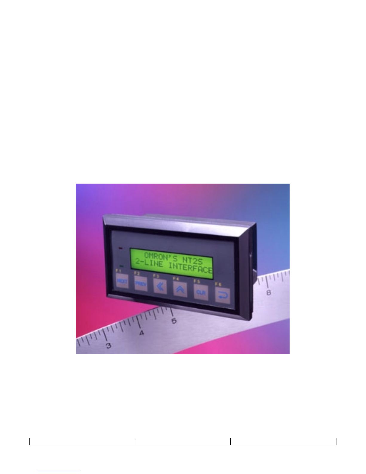
NT2ST is used with NT2S-SF121B-E and NT2S-SF122B-E products. These products are
compact but highly functional operator interfaces and NT2ST is designed to be extremely
flexible to take advantage of this functionality.
The bright LED back light and 2 x 16 character screen provide a highly visible display for
showing fixed or scrolling text messages, bit controlled text, and numerical data.
Special screen types exist for simplifying data entry. Navigation can be achieved using
programmed function keys, configuring a LINK screen, or chaining message screens that change
on a timer. Six function keys provide many options for operator control and data entry.
Function keys can be programmed locally for each screen, or globally for the project, to perform
tasks which include momentary, set on, set off, and toggle bit control, as well as numerous
numeric value control tasks.
The Windows based program, NT2ST, provides many tools to achieve flexible solutions. Follow
this quick start guide to gain an overall understanding of the layout of this software tool.
This document assumes the user is familiar with the operation of programs within Windows and
basic PLC concepts. Consult a technical resource for answers to basic PLC questions.
2. NT2S OPERATION OVERVIEW
The screens displayed on the NT2S are stored in the program memory of the unit. The NT2S
displays the screen number currently stored in the Screen Trigger Register (STR), which is a
PLC memory location. The NT2S remembers the last three STR values and will display them in
order when the current screen is finished displaying.
Numeric data is displayed by placing fields on a screen that reference PLC memory locations.
Up to six numeric fields can be placed on a single screen. Bit status can be displayed on the
screen using bit controlled text.
Navigation from screen to screen can be handled in several ways:
Function keys can be programmed to change the STR. F1 can increment the STR by one,
•
and F2 can decrement the STR by 1. Function keys can also change the STR to a specified
number.
Link screens can be created to navigate a series of screens specified by the user. A link
•
screen is a parent screen which displays a series of child screens. Link screens save
programming time because it automatically defaults to F1 being a NEXT key, and F2 being a
PREV key. Programmer does not have to set these functions up on each screen. Call the link
screen number in the STR to activate the link screen.
Chained screens can be used to automatically cycle through a list of screens. When creating a
•
screen, specify to what screen number it is linked. During operation, the NT2S will continue
to change screens at the rate specified in the MIN TIME field of each screen. The screens
will loop until a STR number is called for a screen not in the chain.
Version 1.03 Page 3
Page 4

3. NT2ST SOFTWARE OVERVIEW
It is recommended that programming steps be performed by accessing the Windows menu items
at the top of the program window. Deactivate the Tool Station (the Desktop cartoon image) by
selecting
Options
menu
, Tool Station
. The tool station should disappear.
Select
at any point within NT2ST to view context sensitive help information. The help
Help
document will provide a more thorough explanation than this document will for most functions.
The sections below are roughly in the order in which a project will be created.
Version 1.03 Page 4
Page 5
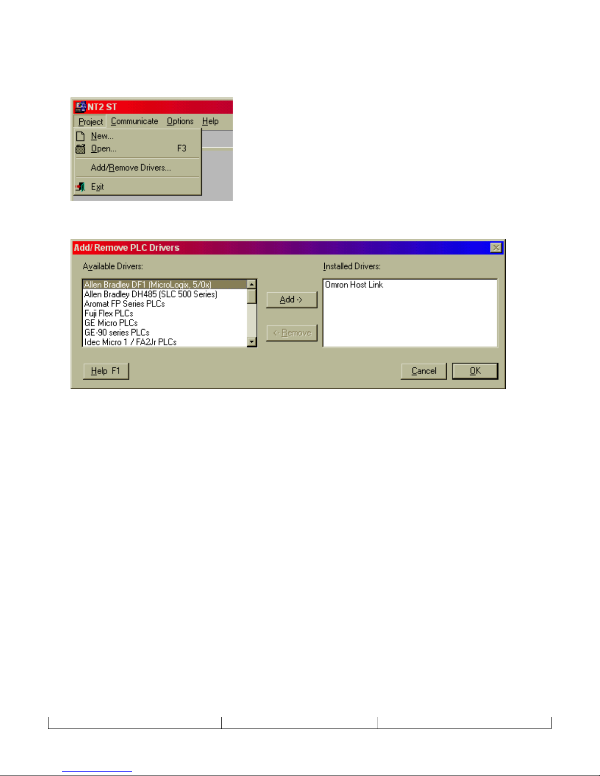
4. ADD/REMOVE DRIVERS
Before beginning the first project, select
Project
and
Add/Remove Drivers
. This menu item is
not available once a project has been created.
A dialog will appear that allows additional PLC models to be added to the PLC selection menu.
Make sure that the PLC needed for the project is included in the list on the right.
Select OK to complete addition of drivers to the project.
Version 1.03 Page 5
Page 6
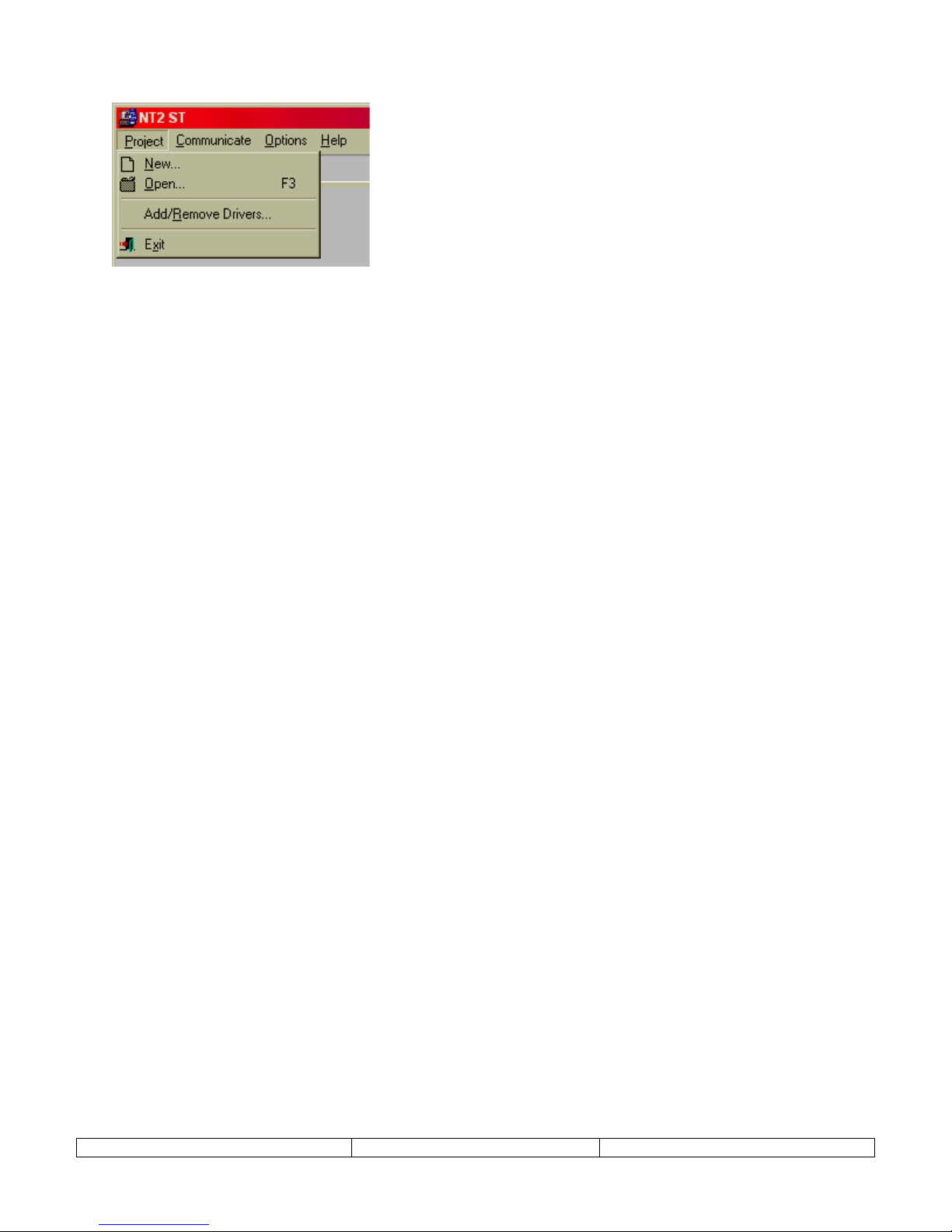
5. CREATE NEW PROJECT
1. Select
New
from the
Project
menu.
2. In the dialog presented, select the PLC and PLC Model from the New project dialog and
select OK.
The PLC model can be changed at any time during the project. From the
select,
PLC Model
, and select a new PLC model from the list. Accept the change by
Project
menu,
clicking on OK. Care must be taken to verify that the tag addresses are valid for the new
PLC model.
(If the brand of PLC required for the project does not appear, refer to the ADD/REMOVE DRIVERS section
above.)
3. Select the NT2S hardware model that will be used for this project. Choose either NT2SSF121B-E or NT2S-SF122B-E and click the CLOSE button.
(If the incorrect NT2S model is selected, the project can be converted at anytime using the file conversion
utility located on the
select OK.)
Project
menu, and select
Model type
. Just open the project and select this menu item and
Version 1.03 Page 6
Page 7
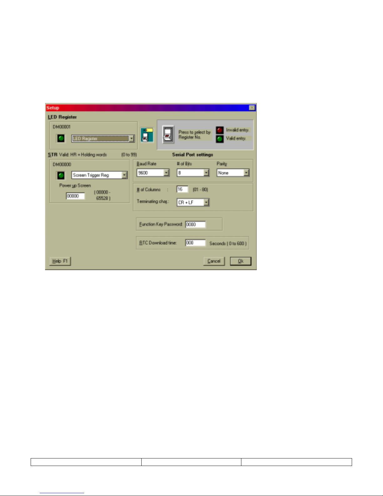
6. PROJECT SETUP
The Setup dialog is used to configure the NT2S operation parameters. Specify the LED register,
screen trigger register, power up screen, serial port settings, function key password, and real time
clock download time. The project setup dialog is accessed from the
Edit
menu,
Setup
menu
item.
Generally, there is no need to change the default settings. The only parameters that need to be
set by the user are Power up screen number and the function key password settings.
LED Register –
type can be referenced for this setting. The default TAG is labeled “LED Register”.
This setting tells the NT2S which TAG to reference for the Screen Trigger Register. Any TAG of the proper
STR –
type can be referenced for this setting. The default TAG is labeled “Screen Trigger Reg”.
Power Up Screen –
number is only referenced internally from the NT2S and is not written down to the STR in the PLC.
Serial Port settings:
RS232, Selectable 7 or 8 bit, Odd, Even or No Parity, No handshake, 300, 600, 1200, 2400, 4800, 9600 or 19200
Baud.
NOTE: Serial Communications specifications apply to the Unit - printer setup and do not affect PC to Unit
communications.
Function Key Password –
password will be used throughout the project.
RTC Download Time (NT2S-SF121B-E only) –
here. The values range from 0 to 600 ( seconds ). 0 means the values will be downloaded as fast as possible. Any
other interval will mean that NT2S will wait for the specific time interval before downloading the value into the
PLC.
Version 1.03 Page 7
This setting tells the NT2S which TAG to reference for the LED Register. Any TAG of the proper
Enter the screen number for the screen that should appear at system start-up. This screen
Set the serial port parameters for serial printer connection. The communication is Serial
This password will be applied to any function key that has the password activated. The
Enter the time interval for downloading the RTC tags to the PLC
Page 8
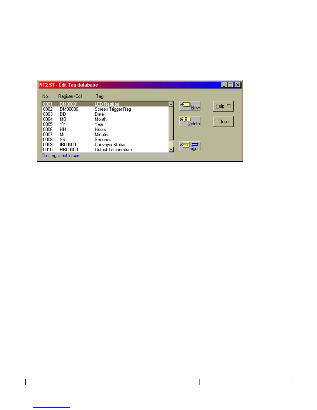
7. TAG DATABASE
Once the project has been created, the very first step should be to define the TAG DATABASE.
The tag database is a list of names (tags) that reference PLC registers or coils (bits). When
programming screens, reference is made to this tag database. Users can choose to reference the
tags either by name or PLC address.
Tags will be referenced while creating the NT2S screens are created. Tags can always be edited
or modified later in the project.
New projects are created a set of default TAGS. For instance, NT2S-SF122B-E has the
following tags:
0001 LED Register |DM00001|
0002 Screen Trigger Reg |DM00000|
NT2S-SF121B-E projects are created with 8 tags. Tags 0003 through 0008 are associated with
the RTC and cannot be directly addressed in NT2ST. Their addresses are offset from the LED
Register address. The tags are defined as follows:
0001 LED Register |DM00001|
0002 Screen Trigger Reg |DM00000|
0003 Date
0004 Month
0005 Year LED Register + 3 (Lower byte) ---- Year (YY)
0006 Hours LED Register + 1 (Higher byte) ---- Hours (HH)
0007 Minutes LED Register + 1 (Lower byte) ---- Minutes (MI)
0008 Seconds LED Register + 2 (Higher byte) ---- Minutes (MI)
LED Register + 2 (Lower byte) ---- Date (DD)
LED Register + 3 (Higher byte) ---- Month (MO)
Version 1.03 Page 8
Page 9
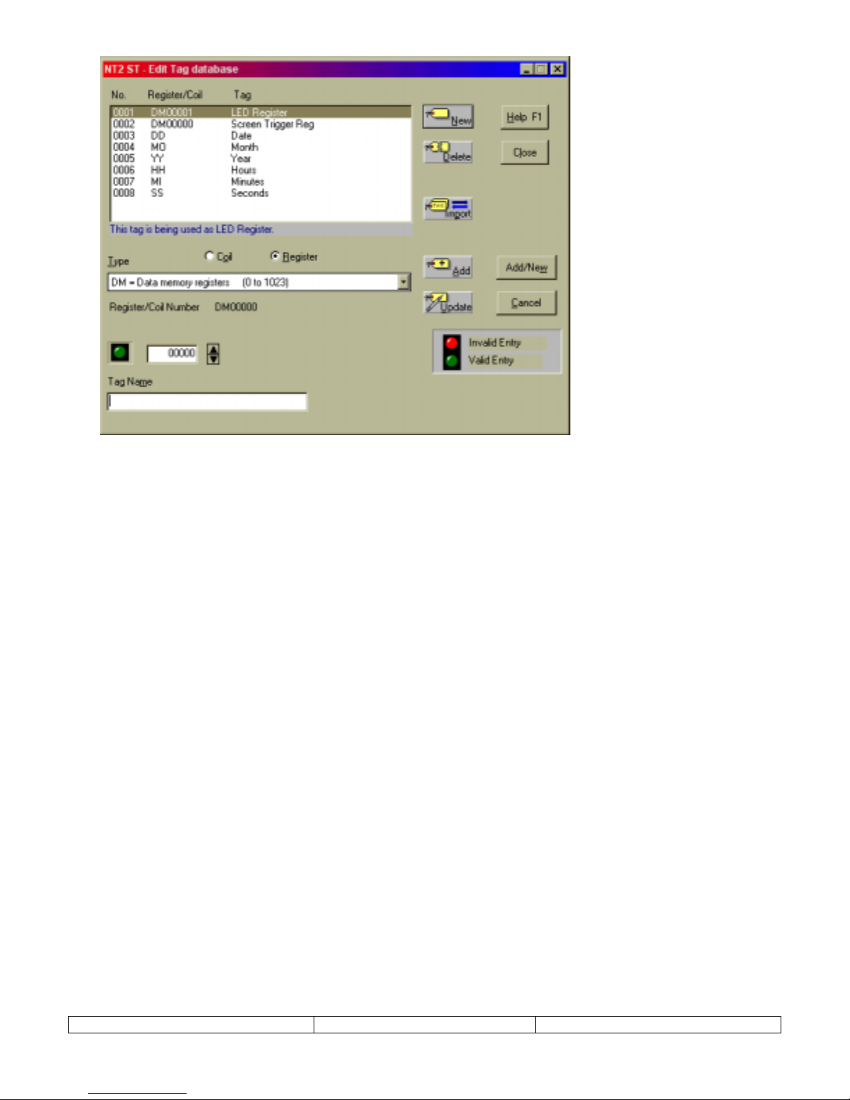
CREATE A REGISTER
A tag can reference an entire word in PLC memory, called a register. Use the following steps to
create a tag for a register:
1. Select
Tag Database
from the
Edit
menu.
2. From the Tag Database editor dialog (shown above), choose NEW.
3. Select the Register button.
4. Choose the PLC memory location from the provided list box.
5. Select the specific register number in the address box provided.
6. Enter a tag name in the lower text box.
7. Select ADD button to complete the creation of the register tag.
CREATE A COIL
A tag can reference a bit in PLC memory, called a coil. Use the following steps to create a tag
for a coil:
1. Select
Tag Database
from the
Edit
menu.
2. From the Tag Database editor dialog, choose NEW.
3. Select the Coil button.
4. Choose the PLC memory location from the provided list box.
5. Select the specific register and bit number in the address box provided.
6. Enter a tag name in the lower text box.
7. Select ADD button to complete the creation of the coil tag.
Version 1.03 Page 9
Page 10
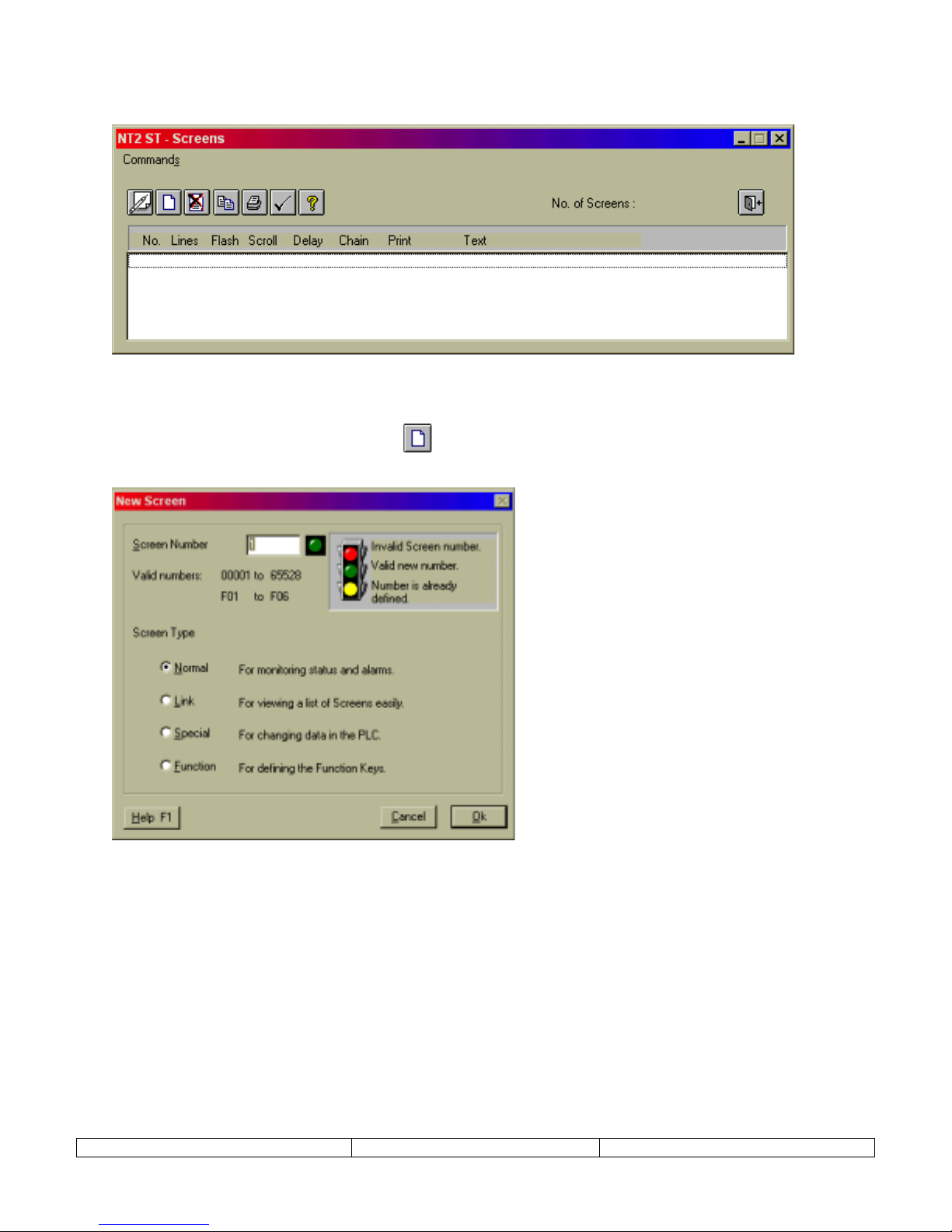
8. EDIT – SCREENS
Launch Screen Editor from EDIT menu. Select SCREENS menu item.
1. From the Edit menu, select the Screens item.
2. Click on the new screen button ! to launch the screen type selection dialog, New
Screen.
3. Four different types of screens can be selected from the New Screen dialog: Normal, Link,
Special, and Function. The following sections will discuss each type of screen. Choose a
screen type, enter a screen number, and select OK to launch the Editing Screen dialog.
Version 1.03 Page 10
Page 11

9. NORMAL SCREEN
Normal screens will make up 90% of all project screens. This type can be used for text message
display, scrolling text messages, display of bit controlled text, display of analog values, and
function key control. The function keys, in red below, can be programmed uniquely for each
normal screen.
The text window in the upper left corner represents the NT2S display window. Some Normal
screen settings include:
DISPLAY HALF – set display for ALL, TOP, or BOTTOM. This is primarily for use with scrolling messages. If
ALL is selected, the scrolling rolls in from the bottom right and then pauses on the top line as the message continues
to scroll in on the bottom. If TOP is selected the message forms a continuous scroll acro ss the top line. Likewise
for the BOTTOM setting.
SCROLL – Set scroll to NO, SLOW, MEDIUM, FAST. Activates scrolling message s. Scro lling messages cannot
display imbedded coil or register values. During NT2S operation, scrolling messages cannot be interrupted. Screen
cannot be changed until the entire scrolling message has been d i splayed.
FLASH – Selection box that allows the NT2S message to blink.
PRINT – Selection box that allows the NT2S screen data to print out the top serial port.
MIN TIME – A minimum time can be assigned to assure an operator can view the screen. If a number is entered in
this field, screens will display for the specified minimum time. This is useful when displaying chained messages,
confirming function key action, or displaying alarm/err or message s .
CHAIN TO – If a screen number is placed in this box, the current screen will be displayed following the specified
screen. The screens in a “chain” will each display for the specified time in the MIN TIME box.
Version 1.03 Page 11
Page 12
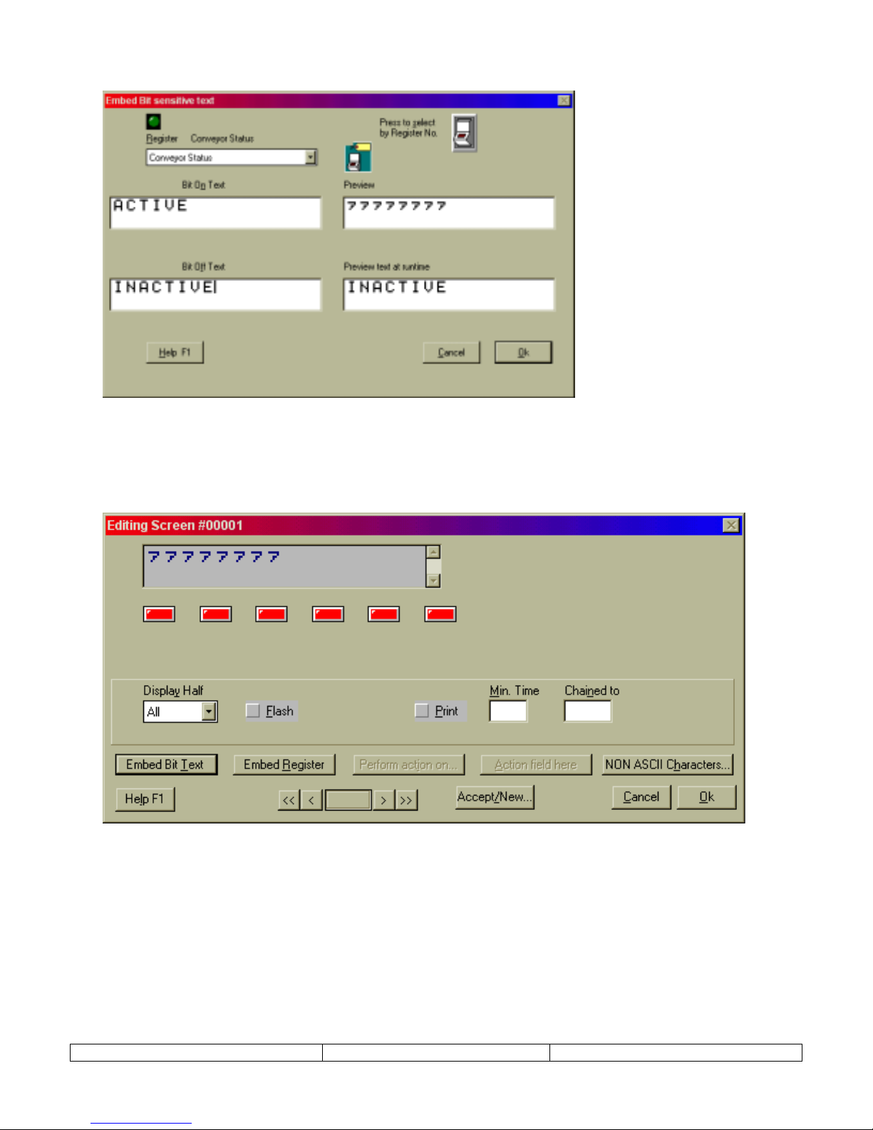
EMBED BIT TEXT – This selection button launches an editing window where letters are assigned to bit val ues.
Once the text is assigned to bit values and OK is selected, text placeholders will appear in the display window.
These placeholders can be positioned by adding characters before the placeholders. In this case, spaces were added
at the far left of the second line to center the text.
The Embedded Bit Text can be edited by selecting a placeholder in the NT2S display window. Choose EDIT from
the menu that will be presented. A DELETE selection will also be pr esented.
Multiple Bit Text elements can be placed on a single NT2S screen. The program will allow up to 32 single
character bit text messages per screen. It is also possible to have one of the states, On or Off, to have no text
displayed.
Version 1.03 Page 12
Page 13
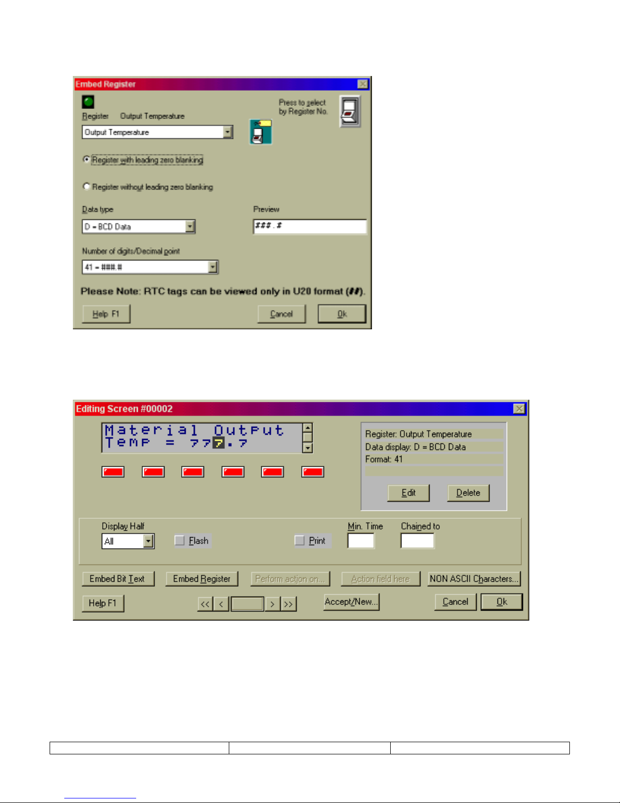
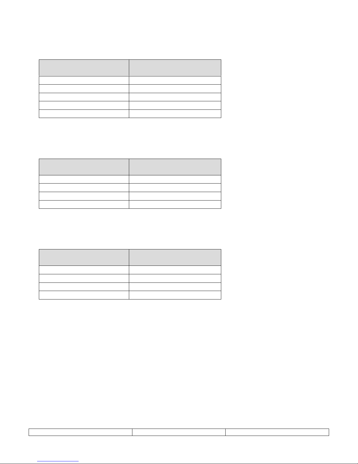
EMBED REGISTER – This selection button launches an editing window for specifying numeric data display. This
editing window allows the selection of data TAG, type, and format.
Once the register is assigned and formatted, select OK. Text placeholders will appear in the display window at the
cursor location. These placeholders can be positioned by adding characters before the placeholders.
The Embedded Register can be edited by selecting a placeholder in the NT2S display window. Choose EDIT from
the menu that will be presented. A DELETE selection will also be pr esented.
Version 1.03 Page 13
Page 14

KEYS FOR SCREEN – The buttons shown in the lower right hand side of the screen dialog are for editing the
function keys for that screen. This would be considered l ocal programming for function keys , effective only for th e
current screen number. Global programming must be performed by creating a Function Key screen, or using the
Edit
menu ,
Function Keys
.
Red keys have not been programmed yet. Green keys have been pr ogrammed.
Double click on the red key to program, or green keys to change programming. The following Editing Key
screens will be displayed. The first dialog box below will be displayed if a register tag is chosen in the register
list box. Choosing a coil tag will display dialog box at the bottom.
Bits can be controlled in several ways. Turn Off and Turn On functions force set the bit to the 0 or 1 positio n.
Toggle alternates the bit between 1 and 0 as the function key is pressed. Hold Off and Hold On set the bit to a 0 or a
1 as long as the function key is held (momentary switch).
Version 1.03 Page 14
Page 15

10. LINK SCREEN
A link screen is a parent screen on which a series of child screens can be displayed. The link
screen is assigned a screen number which can be called by the Screen Trigger Register (STR).
When the link screen number is in the STR, the NEXT(F1) and PREV(F2) function keys can be
used to navigate through the list of specified child screens.
The child screens of the Link Screen can be any existing NORMAL or SPECIAL screen type.
NEXT and PREV functions of the link screen will override any function key programming on F1
and F2 of the child screens.
The progression of screens will follow the order listed in the right window. The order can be
changed using the UP and DOWN keys. Pressing the Next button will show how linked screens
will progress on the NT2S.
Version 1.03 Page 15
Page 16

11. SPECIAL SCREEN
Special screens are used to enter analog values or set digital states. Generally digital states are
more easily set from the Normal screens using function keys and bit controlled text. Only the F1
and F2 keys can be programmed on special screens. F3, F4, F5, and F6 are preprogrammed for
data entry functions.
When creating a Special screen, the first screen to be displayed will be the Edit Action field
dialog.
Operations can be performed on register or coil tags. (Recommend using Special screens only
for changing registers, not coils. Use the function keys of a normal screen for changing coils.)
Operation on Tag include:
-
Edit One Word
Values are entered into the NT2S field using the enter key (F6), up arrow (F3), and left arrow (F4). When
the special screen is displayed, begin the number entry process by pressing the Enter key. The right most
digit will begin blinking. Increment to the digit to the desired value and press the left arrow to shift it over.
Increase the digits and shift them to the left until the desired number is displayed. Then press enter again to
accept the value.
- Numbers are entered highest digit first. Entering the number 521, the user will enter the 5 first, shift it left,
enter the 2 next, shift it left, and then enter a 1 and press enter.
– Assign a value to the sp ecified PLC register using the prepr ogrammed function keys.
A special screen can also perform the following functions.
-
Unsigned Integer - Sends a specified unsigned integer constant value to the specified tag.
-
HEX constant - Sends a specified HEX constant value to the specified tag.
-
Binary constant - Sends a specified Binary constant value to the specified tag.
-
BCD constant - Sends a specified BCD value to the specified tag.
-
Add constant - Sends a specified HEX value to the specified tag.
-
Subtract constant - Sends a specified HEX value to the specified tag .
However, NORMAL screens are recommended for writing constants to memory locations, as
they are much easier to implement.
Version 1.03 Page 16
Page 17

After selecting OK on the Edit Action Field screen, the Editing Screen dialog will appear. The
previous dialog defined the Action Field. Insert the Action Field on to the NT2S screen by
clicking on the ACTION FIELD HERE button on the lower right. Enter text to complete this
screen. Click on the OK button.
Version 1.03 Page 17
Page 18

12. FUNCTION SCREEN
Function screens allow function keys to be defined globally. Function key screens, which can be
created for each key, can have the screen numbers F01, F02, F03, F04, F05, F06. A pop-up
message can be programmed to appear when the function key is pressed. This feature is not
available when programming NORMAL screen function keys. The pop up message is an easy
way to confirm function key key-strokes.
The programming of these Global function keys can be overridden by local function key
programming. It will NOT replace local programming that has already been done. Only keys
with no local programming will perform the global tasks.
Programming begins by clicking on the function key that requires programming. Configure the
action of the function key by clicking on PERFORM ACTION ON button.
Once the action is set, you may choose to enter text in the text window at the upper left. If text is
entered here, a message will be displayed when that function key is pressed. If the field is left
blank, the screen will not change from the current screen.
Bit controlled text, and register information can be placed on the function key pop-up screen
using the EMBED BIT TEXT and EMBED REGISTER buttons in the lower left corner of the
screen.
Select ACCEPT CHANGES TO KEY button when finished programming a function key. Select
another function key number to edit, or select the CLOSE button.
When utilizing the pop-up window feature for the global function keys, it is necessary to enter a
MIN TIME for the screen to display. If no MIN TIME is specified the screen will appear to
quickly to read. Follow the instructions below for editing a Function Key screen to gain access
to this setting.
Version 1.03 Page 18
Page 19

There are two ways to edit a programmed function key screen. Use the
on the
menu item to access the Function Key editing dialog above. Or, click on the screen
Edit
Function Keys
number, F0#, as it appears in the SCREENS dialog, as highlighted below.
The following screen will appear.
selection
Click on the PERFORM ACTION ON button to change global function key program. Enter
MIN TIME to control the time of display of function key message.
Version 1.03 Page 19
Page 20

13. SPECIAL PROGRAMMING NOTES
STR Control from a Function Key
Any function key can be programmed to change the screen by sending a new value to the STR in
the PLC. The STR is defined in the tag database as the Screen Trigger Register tag. The PLC
register will store the value in HEX, so select HEX Constant for the function key operation. If
the user needs to change to screen 25, enter the value 25 in the HEX constant field and the NT2S
will send the HEX value 19 to the STR. Screen 25 will be displayed.
STR Control from the PLC
Since the display can have screen numbers up to 65,528 and the STR is only a four digit register,
the STR is always Hexadecimal. Manipulate the STR in HEX when changing screens from the
PLC. For example, if screen 12 is to be displayed, write the value 000C to the STR. This is
usually done with a copy type command in the PLC ladder program.(Function 21-MOV for
Omron)
Function Key Control Definitions
When programming function keys to control bits in the PLC there are five options for the type of
bit control. After selecting one of the keys you must define a coil tag or address. Next you
choose one of five “Operations” on that tag. The Five Operations and there effect on the PLC
address are as follows:
TURN ON –
Performs a FORCE SET of that bit in the PLC. No other bits in that register are affected
TURN OFF –
Performs a FORCE RESET of that bit in the PLC. No other bits in that register are affected
TOGGLE –
Performs a FORCE SET first time the key is pressed then a FORCE RESET the next time. No
other bits in that register are affected
HOLD ON –
If the bit is ON, there will be no change to the bit. If the bit is OFF the display performs a
FORCE SET of that bit when the key is pressed and a FORCE RESET when released. No other
bits in that register are affected
HOLD OFF –
If the bit is OFF, there will be no change to the bit. If the bit is ON the display performs a
FORCE RESET of that bit when the key is pressed and a FORCE SET when released. No other
bits in that register are affected
Version 1.03 Page 20
Page 21

Entering Text on Second Line of Display
An NT2S can display messages on the top and bottom line for a particular screen. NT2ST
requires a simple step to begin typing text on the second line of the display. Enter characters on
the top line until the cursor is just past the end of the line.
Type any character on the keyboard to initiate the second line. This character will be the first
character on the second line.
Type the second line as it should appear on the NT2S display.
If the characters need to be centered on the second line, click on the first character of the second
line with the mouse button and add spaces using the keyboard.
Remember, the second line can begin with a space, but it cannot be initiated with a space.
Version 1.03 Page 21
Page 22

14. COMMUNICATION CABLES SPECIFICATIONS
OMRON CABLES
NT2S Program Download Cable
Use the standard Omron PLC and NT programming cables:
C200HS-CN220-EU
C200H-CN229-EU
NT2S-SF121B-E pin Designations
NT2S Port PIN #
Designation
Female DB9 Port
2 TX232 (Transmit RS232)
3 RXD (Receive RS232/CMOS)
4&5 Circuit GND
6 VCC (+5V)
7 TXD (Transmit CMOS)
8 PLC Attach
9 Direction Control
NT2S-SF122B-E pin Designations
NT2S Port PIN #
Designation
Male DB9 Port
2 Direction Control
3 TX232 (Transmit RS232)
4 VCC (+5V)
5 Circuit GND
6 TXD (Transmit CMOS)
7 RXD (Receive RS232/CMOS)
8 (same as 7) RXD (Receive RS232/CMOS)
NT2S-SF123B-E pin Designations
NT2S Port PIN #
Designation
Male DB9 Port
4 VCC (+5V)
5 Circuit GND
6 TXD (Transmit CMOS)
7 RXD (Receive CMOS)
8 (same as 7) RXD (Receive CMOS)
Version 1.03 Page 22
Page 23

Omron PLC Peripheral Port Cable (NT2S-SF121B-E):
NT2S Port PIN #
Omron Peripheral Port PIN #
Male DB9
7 TXD (CMOS) 5 RXD
3 RXD 7 TXD
5&9 10 Ground
Short 3, 15, & 17
Short 11 & 16
Metal cover to shield Metal cover to shield
NT2S-CN21#
Omron PLC Peripheral Port Cable (NT2S-SF122B-E and NT2S-SF123B-E):
NT2S Port PIN #
Omron Peripheral Port PIN #
NT2S-CN22#
Male DB9
1&5 shorted
4 Green VCC (+5V) 1 5V source
6 White TXD (CMOS) 5 RXD
7 Yellow RXD (CMOS) 7 TXD
1&5 Brown (GND) 10 Ground
Short 3, 15, & 17
Short 11 & 16
Metal cover to shield Metal cover to shield
Omron PLC Serial Port Connection with NT2S-SF
121
B-E
Tested an NT2S-SF121B-E by connecting it to the Host Link (RS-232C) port on a CQM1 PLC
and it worked fine. This cable is needed to connect to Host Link and has the following pinouts:
NT2S Port PIN #
Male DB9 on cable
Omron Serial Port PIN #
Male DB9 on cable
2 TXD (RS232) 3 RXD
3 RXD 2 TXD
5&9 Ground 9 Ground
1 to shield
4 to 5 short
Omron PLC Serial Port Connection with NT2S-SF
Tested an NT2S-SF122B-E connection to the following PLCs:
- C200H
- CQM1 – directly to serial port
- CPM2A - directly to serial port
- CQM1H – Con nect to Serial Port
- CPM2C – Connect to CPM2C-CN111
– directly to serial port
α
NT2S Port PIN #
Female DB9 on cable
3 TXD (RS232) 3 RXD
4 VCC (+5V) 6 5V Source
2 & 5 Ground 9 Ground
7 RXD (RS232) 2 TXD
Version 1.03 Page 23
B-E
122
Omron Peripheral Port PIN #
Male DB9 on cable
1 to shield
4 to 5 short
Page 24

Allen-Bradley Cables
MicroLogix (DF1 protocol)
NT2S-SF121B-E Port PIN #
Male DB9 on cable
AB Micrologix 1000 & 1500
8 PIN MINIDIN (from AB)
2 TXD (RS232) 4 RXD
3 RXD 7 TXD
5&9 Ground 2 Ground
2 to shield
Allen Bradley SLC 5/0x (DF1 protocol)
NT2S-SF121B-E Port PIN #
Male DB9 on cable
AB SLC 5/0x
Male DB9 on cable
2 TXD (RS232) 2 RXD
3 RXD 3 TXD
5&9 Ground 5 Ground
5 to shield
Version 1.03 Page 24
Page 25

GE Micro Cables
Communication cable connections
HMI end Designation PLC end
SPECIFICATION NOT YET AVAILABLE
: GE Micro
Version 1.03 Page 25
Page 26

Modicon Cables
Modicon (Modbus master)
NT2S-SF121B-E Port PIN #
Male DB9 on cable
Modicon Modbus Master
8 x 8 Modular Connector
2 TXD (RS232) 4 RXD
3 RXD 3 TXD
5&9 Ground 5 Ground
5 to shield
Version 1.03 Page 26
Page 27

Keyence Cables
Keyence KV Series
NT2S-SF121B-E Port PIN #
Male DB9 on cable
Keyence KV Series PLC
4 x 4 Modular Connector
2 TXD (RS232) 3 RXD
3 RXD 1 TXD
5&9 Ground 1 Ground
1 to shield
Version 1.03 Page 27
Page 28

Toshiba Cables
Toshiba PLC T1
NT2S-SF121B-E Port PIN #
Male DB9 on cable
Toshiba PLC T1
8 PIN Minidin Connector
2 TXD (RS232) 8 RXD
3 RXD 6 TXD
5&9 Ground 5 Ground
5 to shield
Toshiba PLC T2
NT2S-SF121B-E Port PIN #
Male DB9 on cable
Toshiba PLC T2
8 PIN Minidin Connector
2 TXD (RS232) 2 RXD
3 RXD 3 TXD
5&9 Ground 5 Ground
5 to shield
Version 1.03 Page 28
Page 29
Koyo Cables
Koyo 405 Series
NT2S-SF121B-E Port PIN #
Male DB9 on cable
Koyo 405 Series
8PIN Minidin Connector
2 TXD (RS232) 3 RXD
3 RXD 2 TXD
5&9 Ground 13, 14, 15 Ground
13, 14, 15 Shield
1, 7, 8 Short
Koyo DL 205
NT2S-SF121B-E Port PIN #
Male DB9 on cable
Koyo 205 Series
6 x 6 Modular
2 TXD (RS232) 3 RXD
3 RXD 4 TXD
5&9 Ground 1 Ground
1 Shield
Koyo DL 305
NT2S-SF121B-E Port PIN #
Male DB9 on cable
Koyo 305 Series
4 x 4 Modular
2 TXD (RS232) 1 RXD
3 RXD 2 TXD
5&9 Ground 4 Ground
4 Shield
Version 1.03 Page 29
Page 30
15. NT2S SPECIFICATIONS
Features Description NT2S-SF121B-E NT2S-SF122B-E
Programming package Windows Software Package - NT2ST Yes Yes
ASCII Controlled Messages ASCII in PLC registers is displayed on the NT2S screen. Pointer in PLC
memory tells NT2S which register to display. Pointers placed in that
PLC register point to data value to be displayed.
Multi-vendor support Omron, Allen-Bradley Micrologix and SLC 5/0x, GE Micro, Modicon,
Keyence KV Series, Toshiba T Series, Koyo 305, 405, and DL205
Series.
Memory type EEPROM 8k 8k
Power 24vdc Term i nals or PLC Peripheral Port 5 vdc 24 vdc 5 vdc
Enclosure ratings IP65 Yes Yes
Standards CE, cCSAus Yes Yes
Ambient Op Rating 0 to 50 C Ok Ok
Storage temp -20 to + 60 C Ok Ok
Ambient Humidity 35 to 85 % with no condensation Ok Ok
Ambient Environment No c o rrosive gasses Ok Ok
Weight 400 g Ok Ok
Panel Fitting 2 c l amps Ok Ok
Face Dimensions Dimensions of NT2S Front Bezel (mm) 109W x 60H 109W x 60H
Rear Unit Dimensions Dimensions for portion of NT2S that enters panel (mm) 91W x 44H x 44D 91W x 44H x 44D
Panel Cutout Recommended panel cutout Dimensions (mm) 1/8 DIN 92W x 45H 92W x 45H
Display Specifications
Display Lines * Characters 2 * 16 2 * 16
Character Height mm 4.35 mm 4.35 mm
Backlit LED Backlight Ok Ok
Effective display area mm 60 x 13 mm 60 x 13 mm
Indicators Red and Green LED indicators. Yes Yes
Number of screens Max number of screens if only text messages are used. Adding function
keys, scrolling messages, etc. decreases the maximum number of
screens.
Data Format HEX, BCD, OCT, BIN, signed, unsigned Ok Ok
Function Keys
Available Function keys Number of user programmable function keys 6 6
Global Function Key Program Function key can be programmed for global functions. Key program is
effective throughout the NT2S program.
Local Function Key Program Function key can be programmed uniquely for each screen. Yes Yes
No No
Yes No
250 250
Yes Yes
Function Key Binary Action Momentary, Toggle On, Toggle Off, Set On, Set Off. Yes Yes
Function Key Numeric Action Set constant value, increment, or decrement by a constant value to PLC
register.
Numeric Entry S pecial screen uses arrow, clear, and enter keys to input numeric values
to PLC register.
Function Key Screen Global Function key actions can be linked to a Function Key screen that
displays upon activation of that function key. This can be used to
confirm function key action.
Password Protect Any Key Password can be activated for any function key. Yes Yes
Yes Yes
Yes Yes
Yes Yes
Version 1.03 Page 30
Page 31
Communications
COM port 1 Programming & Printi ng port DB9 connector
COM port 2 Host PLC Communicati ons DB9 connector
Special functions
Real Time Clock 2-digit Year, Month, Date, Hour, Minut e, Second Yes NA
2 User definable LEDs Red and Green LED can be controlled from PLC Yes Yes
Scrolling Messages Scroll messages up to 256 characters. Yes Yes
Flashing Display Specify for backli ght t o flash. Yes Yes
Minimum Display Time Define minimum display time for a screen. Yes Yes
Screen chaining Chained screens will display in sequential fashion, each displaying for
the set minimum display time.
Link Screen Create a list of screens that can be navigated using the NEXT (F1) and
PREVIOUS (F2) keys.
Bar Graph Display Displ ay numeric values as a bargraph. Yes Yes
Print Functions
Print Screen Configure serial communications port to commumicate with a printer.
Print screen text and displayed PLC data values can be printed.
RS-232 Port
CMOS/RS-232 port
Yes Yes
Yes Yes
Yes Yes
DB9 connector
RS-232 Port
DB9 connector
CMOS port
Version 1.03 Page 31
 Loading...