

Page 1

Cat. No. V001-E1-2
Programmable Terminal
NT20M/NT2000M
Page 2

NT20M/NT2000M
Programmable Terminal
Operation Manual
Revised September 1993
Page 3

iv
Page 4

v
Notice:
OMRON products are manufactured for use according to proper procedures by a qualified operator
and only for the purposes described in this manual.
The following conventions are used to indicate and classify warnings in this manual. Always heed the
information provided with them.
Indicates information that, if not heeded, could result in loss of life or serious
injury.
Indicates information that, if not heeded, could result in minor injury or damage to the product.
Product References
All OMRON products are capitalized in this manual. The word “Unit” is also capitalized when it refers
to an OMRON product, regardless of whether or not it appears in the proper name of the product.
The abbreviation “Ch,” which appears in some displays and on some OMRON products, often means
“word” and is abbreviated “Wd” in documentation in this sense.
The abbreviation “PC” means Programmable Controller and is not used as an abbreviation for anything else.
IBM and IBM PC/AT are registered trademarks of International Business Machines Corporation.
MS-DOS is a registered trademark of Microsoft Corporation.
Visual Aids
The following headings appear in the left column of the manual to help you locate different types of
information.
Indicates information of particular interest for efficient and convenient operation of the product.
Indicates lists of one sort or another, such as procedures, precautions, etc.
OMRON, 1991
All rights reserved. No part of this publication may be reproduced, stored in a retrieval system, or transmitted, in any
form, or by any means, mechanical, electronic, photocopying, recording, or otherwise, without the prior written permission of OMRON.
No patent liability is assumed with respect to the use of the information contained herein. Moreover, because OMRON is
constantly striving to improve its high-quality products, the information contained in this manual is subject to change
without notice. Every precaution has been taken in the preparation of this manual. Nevertheless, OMRON assumes no
responsibility for errors or omissions. Neither is any liability assumed for damages resulting from the use of the information contained in this publication.
DANGER!
Caution
Note
1, 2, 3...
Page 5

vi
Page 6

vii
TABLE OF CONTENTS
SECTION 1
Introduction 1. . . . . . . . . . . . . . . . . . . . . . . . . . . . . . . . . . . . .
1-1 Introduction 2. . . . . . . . . . . . . . . . . . . . . . . . . . . . . . . . . . . . . . . . . . . . . . . . . . . . . . . . . . . . .
1-2 Features 2. . . . . . . . . . . . . . . . . . . . . . . . . . . . . . . . . . . . . . . . . . . . . . . . . . . . . . . . . . . . . . . .
1-3 NT-series Terminology 3. . . . . . . . . . . . . . . . . . . . . . . . . . . . . . . . . . . . . . . . . . . . . . . . . . . . .
1-4 Models 4. . . . . . . . . . . . . . . . . . . . . . . . . . . . . . . . . . . . . . . . . . . . . . . . . . . . . . . . . . . . . . . . .
1-5 Support Tool 6. . . . . . . . . . . . . . . . . . . . . . . . . . . . . . . . . . . . . . . . . . . . . . . . . . . . . . . . . . . . .
1-6 System Configuration 6. . . . . . . . . . . . . . . . . . . . . . . . . . . . . . . . . . . . . . . . . . . . . . . . . . . . . .
1-7 Nomenclature and Functions 8. . . . . . . . . . . . . . . . . . . . . . . . . . . . . . . . . . . . . . . . . . . . . . . .
SECTION 2
Settings and Installation 13. . . . . . . . . . . . . . . . . . . . . . . . . . .
2-1 Switch Settings 14. . . . . . . . . . . . . . . . . . . . . . . . . . . . . . . . . . . . . . . . . . . . . . . . . . . . . . . . . . .
2-2 Installation Environment 16. . . . . . . . . . . . . . . . . . . . . . . . . . . . . . . . . . . . . . . . . . . . . . . . . . .
2-3 Dimensions 17. . . . . . . . . . . . . . . . . . . . . . . . . . . . . . . . . . . . . . . . . . . . . . . . . . . . . . . . . . . . . .
2-4 Installing in a Panel 18. . . . . . . . . . . . . . . . . . . . . . . . . . . . . . . . . . . . . . . . . . . . . . . . . . . . . . .
2-5 Wiring and Connectors 21. . . . . . . . . . . . . . . . . . . . . . . . . . . . . . . . . . . . . . . . . . . . . . . . . . . . .
2-6 RS-232C Interface Connector 26. . . . . . . . . . . . . . . . . . . . . . . . . . . . . . . . . . . . . . . . . . . . . . .
2-7 Mounting Function Key Units (to DN-type PT s) 27. . . . . . . . . . . . . . . . . . . . . . . . . . . . . . . . .
SECTION 3
Initial Operation 29. . . . . . . . . . . . . . . . . . . . . . . . . . . . . . . . .
3-1 Powering Up 30. . . . . . . . . . . . . . . . . . . . . . . . . . . . . . . . . . . . . . . . . . . . . . . . . . . . . . . . . . . . .
3-2 Initialization 30. . . . . . . . . . . . . . . . . . . . . . . . . . . . . . . . . . . . . . . . . . . . . . . . . . . . . . . . . . . . .
3-3 Transferring Data to and from the Support Tool 32. . . . . . . . . . . . . . . . . . . . . . . . . . . . . . . . .
3-4 Initial Settings 33. . . . . . . . . . . . . . . . . . . . . . . . . . . . . . . . . . . . . . . . . . . . . . . . . . . . . . . . . . .
SECTION 4
Display Functions 35. . . . . . . . . . . . . . . . . . . . . . . . . . . . . . . .
4-1 Character Displays on Screen 36. . . . . . . . . . . . . . . . . . . . . . . . . . . . . . . . . . . . . . . . . . . . . . .
4-2 Normal Screen Changes 36. . . . . . . . . . . . . . . . . . . . . . . . . . . . . . . . . . . . . . . . . . . . . . . . . . . .
4-3 Continuous Screens 37. . . . . . . . . . . . . . . . . . . . . . . . . . . . . . . . . . . . . . . . . . . . . . . . . . . . . . .
4-4 Overlapping Screens 38. . . . . . . . . . . . . . . . . . . . . . . . . . . . . . . . . . . . . . . . . . . . . . . . . . . . . .
4-5 Numeric Displays 39. . . . . . . . . . . . . . . . . . . . . . . . . . . . . . . . . . . . . . . . . . . . . . . . . . . . . . . . .
4-6 Character Strings 40. . . . . . . . . . . . . . . . . . . . . . . . . . . . . . . . . . . . . . . . . . . . . . . . . . . . . . . . .
4-7 Bar Graphs 41. . . . . . . . . . . . . . . . . . . . . . . . . . . . . . . . . . . . . . . . . . . . . . . . . . . . . . . . . . . . . .
4-8 Lamps 41. . . . . . . . . . . . . . . . . . . . . . . . . . . . . . . . . . . . . . . . . . . . . . . . . . . . . . . . . . . . . . . . . .
4-9 Graphics Display 42. . . . . . . . . . . . . . . . . . . . . . . . . . . . . . . . . . . . . . . . . . . . . . . . . . . . . . . . .
4-10 Special Controls 42. . . . . . . . . . . . . . . . . . . . . . . . . . . . . . . . . . . . . . . . . . . . . . . . . . . . . . . . . .
SECTION 5
Input Functions 45. . . . . . . . . . . . . . . . . . . . . . . . . . . . . . . . . .
5-1 On-screen Switch Inputs 46. . . . . . . . . . . . . . . . . . . . . . . . . . . . . . . . . . . . . . . . . . . . . . . . . . .
5-2 Inputting Numeric Settings 47. . . . . . . . . . . . . . . . . . . . . . . . . . . . . . . . . . . . . . . . . . . . . . . . .
5-3 Standalone Function 50. . . . . . . . . . . . . . . . . . . . . . . . . . . . . . . . . . . . . . . . . . . . . . . . . . . . . . .
SECTION 6
System Menu 51. . . . . . . . . . . . . . . . . . . . . . . . . . . . . . . . . . . .
6-1 Configuration of System Menu 52. . . . . . . . . . . . . . . . . . . . . . . . . . . . . . . . . . . . . . . . . . . . . .
6-2 System Menu 53. . . . . . . . . . . . . . . . . . . . . . . . . . . . . . . . . . . . . . . . . . . . . . . . . . . . . . . . . . . .
6-3 Maintenance Mode 53. . . . . . . . . . . . . . . . . . . . . . . . . . . . . . . . . . . . . . . . . . . . . . . . . . . . . . . .
6-4 Memory Switch Settings 60. . . . . . . . . . . . . . . . . . . . . . . . . . . . . . . . . . . . . . . . . . . . . . . . . . .
Page 7

viii
SECTION 7
Online Transfer 63. . . . . . . . . . . . . . . . . . . . . . . . . . . . . . . . . .
7-1 Transferring Screen Data 64. . . . . . . . . . . . . . . . . . . . . . . . . . . . . . . . . . . . . . . . . . . . . . . . . . .
7-2 Host to PT 64. . . . . . . . . . . . . . . . . . . . . . . . . . . . . . . . . . . . . . . . . . . . . . . . . . . . . . . . . . . . . . .
7-3 PT to Host 64. . . . . . . . . . . . . . . . . . . . . . . . . . . . . . . . . . . . . . . . . . . . . . . . . . . . . . . . . . . . . . .
7-4 Online Transmission and Resume Function 65. . . . . . . . . . . . . . . . . . . . . . . . . . . . . . . . . . . . .
SECTION 8
Maintenance and Inspection 67. . . . . . . . . . . . . . . . . . . . . . .
8-1 Checking Operation 68. . . . . . . . . . . . . . . . . . . . . . . . . . . . . . . . . . . . . . . . . . . . . . . . . . . . . . .
8-2 Changing the Lithium Backup Battery 69. . . . . . . . . . . . . . . . . . . . . . . . . . . . . . . . . . . . . . . .
8-3 Replacing the Backlight 70. . . . . . . . . . . . . . . . . . . . . . . . . . . . . . . . . . . . . . . . . . . . . . . . . . . .
8-4 Maintenance and Inspection 71. . . . . . . . . . . . . . . . . . . . . . . . . . . . . . . . . . . . . . . . . . . . . . . . .
Appendices 73. . . . . . . . . . . . . . . . . . . . . . . . . . . . . . . . . . . . . .
A. Standard Models 73. . . . . . . . . . . . . . . . . . . . . . . . . . . . . . . . . . . . . . . . . . . . . . . . . . . . . . . . . .
B. Specifications 75. . . . . . . . . . . . . . . . . . . . . . . . . . . . . . . . . . . . . . . . . . . . . . . . . . . . . . . . . . . .
Index 79. . . . . . . . . . . . . . . . . . . . . . . . . . . . . . . . . . . . . . . . . . .
Revision History 81. . . . . . . . . . . . . . . . . . . . . . . . . . . . . . . . .
Page 8

ix
About this Manual:
Programmable Terminals (PTs) are terminals used mainly at FA production sites. The PT is connected to a
host such as a Programmable Controller or an FA Computer, and is used to display the operating conditions of various devices and equipment. In addition, it can be used as a control panel with lamps and
switches, or it can be used for inputting data. This manual describes the installation and operation of the
NT20M and NT2000M Programmable Terminals and includes the sections described below. Further information is pro v i ded on manuals on the Host Interface Units and Support Tool. Refer to the list in Section
1 Introduction.
Please read this manual completely and be sure you understand the information provide before attempting to install and operation a Programmable Terminal.
Section 1 introduces the PTs, describes the terminology used in this manual, and provides examples
of system configurations for programming and operation.
Section 2 provides procedures and specifications required to set up a PT system, including hardware
switch settings and installation.
Section 3 provides steps required for initial PT operation.
Section 4 describes functions used to create screens and control display attributes on the PT. In-
cluded is automatic transfer of data from the host computer via character string and numeral tables.
Section 5 describes functions used to input data on-screen and transfer it to the host computer via
the numeral table.
Section 6 describes basic data transfer and maintenance functions.
Section 7 describes transferring screens online to and from the host computer.
Section 8 provides troubleshooting and basic maintenance methods, including battery replacement.
Appendices of OMRON products used with PTs and PT specifications are provided at the back of the
manual.
Page 9

1
SECTION 1
Introduction
This section provides information necessary to familiarize you with the features and parts of a PT system.
1-1 Introduction 2. . . . . . . . . . . . . . . . . . . . . . . . . . . . . . . . . . . . . . . . . . . . . . . . . . . . . . . . . . . . .
1-2 Features 2. . . . . . . . . . . . . . . . . . . . . . . . . . . . . . . . . . . . . . . . . . . . . . . . . . . . . . . . . . . . . . . .
1-3 NT-series Terminology 3. . . . . . . . . . . . . . . . . . . . . . . . . . . . . . . . . . . . . . . . . . . . . . . . . . . . .
1-4 Models 4. . . . . . . . . . . . . . . . . . . . . . . . . . . . . . . . . . . . . . . . . . . . . . . . . . . . . . . . . . . . . . . . .
1-4-1 NT20M Programmable Terminals 4. . . . . . . . . . . . . . . . . . . . . . . . . . . . . . . . . . . . .
1-4-2 NT2000M Programmable Terminals 5. . . . . . . . . . . . . . . . . . . . . . . . . . . . . . . . . . .
1-4-3 12-key Function Key Units (for DN-type) 6. . . . . . . . . . . . . . . . . . . . . . . . . . . . . .
1-5 Support Tool 6. . . . . . . . . . . . . . . . . . . . . . . . . . . . . . . . . . . . . . . . . . . . . . . . . . . . . . . . . . . . .
1-6 System Configuration 6. . . . . . . . . . . . . . . . . . . . . . . . . . . . . . . . . . . . . . . . . . . . . . . . . . . . . .
1-7 Nomenclature and Functions 8. . . . . . . . . . . . . . . . . . . . . . . . . . . . . . . . . . . . . . . . . . . . . . . .
1-7-1 NT20M-Dj121-V2/Dj13j 8. . . . . . . . . . . . . . . . . . . . . . . . . . . . . . . . . . . . . . . .
1-7-2 NT2000M-Dj131 10. . . . . . . . . . . . . . . . . . . . . . . . . . . . . . . . . . . . . . . . . . . . . . . . .
Page 10

2
1-1 Introduction
This manual describes the installation and operation of NT20M and
NT2000M Programmable Terminals (PTs). Both models can come with or
without touch panels. Programmable Terminals have three main functions: 1)
monitoring operating conditions, 2) directing on-site personnel, and 3) inputting data.
1) PTs can monitor, in real time, system and equipment operating conditions,
production quantities, and so on. The PT display can show, for example,
whether the production line is operating normally, and what percentage of the
production target has been met. Bar graphs can be continually updated as
data is received from the host. On-screen characters can be displayed as
plain, reverse video, blinking, or reverse blinking. In addition, lamps, bar
graphs, and figures can all be created. Screen data can be registered at the
PT in advance, and can be displayed simply by transmitting the appropriate
screen number from the host.
2) PTs can inform on-site personnel of current conditions that need to be addressed. Depending on the nature of the situation, built-in or external buzzers
can be sounded to alert personnel to problems that have developed. Depending on factors such as distance from the host, the number of devices
connected, and the response time, any of a variety of communications methods may be selected.
3) PTs can input data for controlling certain operations and communicating
information to the host. Setting switches and a ten-key pad allows a PT to be
used as a control panel. In the example shown below, touch switches used
for inputs to the host are displayed. When this screen is displayed, the onsite operator can control a device by means of touch switches.
Aside from touch switches, the PT can provide inputs by means of numeric
settings and externally connected switches. The illustration below shows a
numeric setting screen that can be used for inputting numeric data.
The screens used for these operations can be created in advance by using
the “Support Tool” software on a personal computer. The screen data that is
created using the Support Tool can be printed out, saved to a diskette, or
transferred to the PT. Either an FA Computer or a Programmable Controller
can be used as the host.
1-2 Features
Clear Display The display is extremely clear due to an STN liquid crystal display with a
backlight. For long life, the backlight can be set to turn off automatically. With
the NT20M-Dj131 and the NT2000M-Dj131 models, the backlight is replaceable.
By increasing the dot size, the display screen for the NT2000M has been enlarged.
With the NT20M-Dj131 and the NT2000M-Dj131 models, the backlight
can be switched between white and red. It is ordinarily white, but under extreme circumstances it can be switched to red for greater visibility.
Up to 250 screens can be registered. A total of 256 touch switches and rectangular or circular lamps can be created and registered, with up to 64 touch
switches and/or lamps for a single screen. In addition, up to 32 messages
(strings of 32 characters) and 128 eight-digit numbers can be registered. Fig-
Industry’s Largest LCD
Screen
Industry’s First CFL
Two-color Backlight Display
Display Functions
Features Section 1-1
Page 11

3
ures and bar graphs can also be created and displayed. Marks (16 dots x 16
dots) can also be created with the NT20M/NT600M Support Tool and displayed.
Up to 64 touch switch inputs can be registered per screen for Terminals with
a touch panel (DT).
Drip-proof, Oil-proof Panel The NT20M PTs (except for those connected to the NT20M-FK210) have a
drip-proof front panel structure when the dust cover is mounted to protect the
display area and the key input area. For protection against oil spray, the
front-panel sheets and moulded parts use oil-resistant materials. In addition,
the NT2000M PTs have a completely water-proof structure when the panel is
mounted.
Messages and numbers transferred from the host can be displayed at programmed locations. In addition, numbers from touch panel and function key
inputs can be transferred back to the host.
Five types of Host Interface Unit enable general RS-232C and RS-422 communications, special-purpose SYSMAC BUS (Wired) communications,
C200H Host Interface communications to the C200H, and Host Link direct
connection communications.
System Configuration NT-series Terminals have common communications protocol and peripheral
devices. Select the Terminal you need based on screen size, memory capacity, and host interface.
Program Reusability Programs for communicating with Programmable Controllers are upwardly
compatible so the program can easily be reused when adding functions.
Screens can be changed on-site, without requiring instructions from the host.
At the time when the screens are created by the Support Tool in advance,
screen-changing functions can be allocated to touch switches or function
keys, thereby making it possible to easily change to any screen.
Online Transfer Capability When an RS-232C or RS-422 Interface Unit is mounted to the Host Interface
Unit, screen data can be changed by means of commands from the host.
Direct connection is a function whereby host data areas can be made to directly correspond to PT operations. Ordinarily, operating instructions to the
PT and inputs from the PT are carried out by means of command execution
at the host. The direct connection function eliminates the need for such host
commands and programming, thereby greatly reducing the size and complexity of the host program. Direct connection is possible for PTs with touch
panels when a Host Link Interface Unit is mounted. In addition, the NT20MZASAT-EV4 Support Tool and the NT20M-SMR31-E are required.
1-3 NT-series Terminology
The following are definitions for the names of items in this manual related to
the NT Series of Programmable Terminal and SYSMAC C-series Programmable Controllers.
Abbreviations The following abbreviations are used in the text.
Input Functions
Two-way Communications
Host Interface
Communications
Stand-alone Capability
Direct Connection
NT-series Terminology Section 1-3
Page 12

4
Abbreviation Term Meaning
PT Programmable Terminal Refers to an OMRON NT-series Programmable Terminal.
PC Programmable
Controller
Refers to an OMRON SYSMAC C-series or CV-series Programmable
Controller, or programmable controllers manufactured by other companies.
I/F interface A communications device that connects the Programmable Terminal with
peripheral devices.
I/O input/output Refers to PT and PC inputs and outputs.
SYSMAC Terminology
Terminology Explanation
SYSMAC A generic name for OMRON’s Programmable Controllers.
Host Link System A system employing SYSMAC C-series Host Link Units used to create a communications bus
between PCs, between PCs and PTs, etc.
SYSMAC BUS A remote I/O network created between SYSMAC C-series PCs and input/output devices.
C200H An OMRON SYSMAC C-series Programmable Controller.
NT-series Manuals The NT20M/NT2000M Series and NT600M Series are covered in the four
manuals described below.
Name of Manual Contents Manual No.
NT20M/NT2000M Operation
Manual
This manual provides specifications, functions, and operating
instructions for the NT20M and NT2000M Programmable Terminals.
V001
NT600M Operation Manual This manual provides specifications, functions, and operating
instructions for NT600M Programmable Terminals.
V002
NT-series Host Interface Unit
Operation Manual
This manual covers the commands, controls, and communications
specifications for operating the NT20M and the NT600M. Refer to
this manual when programming host computer communications.
V003
NT20M/NT600M Support Tool
Operation Manual
This manual covers methods for creating screens, including screen
data preparation, switches, lights, and alarms.
V004
NT-series Host Interface Unit
Direct Connection Operation
Manual
This manual covers the Direct Connection feature which has been
added to the Host Interface Unit.
V015
NT-series RS-232C/RS-422
Interface Unit Operation Manual
This manual covers the commands, controls, and communications
specifications for operating the NT20M and the NT600M with the
RS-232C/RS-422 Interface Unit. Refer to this manual when
programming host computer communications.
V016
1-4 Models
1-4-1 NT20M Programmable Terminals
The various NT20M PT models are shown in the table below. Several of
these models employ two-color backlights. The two-color backlight incorporates red and white lights, one of which is selected according to operational
requirements. The two-color backlights are replaceable, and are sold separately.
System ROM is sold separately for all models. Select the System ROM according to the Host Interface Unit that is mounted to the PT, as described in
Host Interface Units and Conforming System ROM on the following page.
NT20M type Model number Backlight Image data memory
With touch panel (DT)
NT20M-DT121-V2 White
I/C socket:
p()
NT20M-DT131 White or red
None of these models come with image data
memor
y
chips mounted. Purchase them
Without touch panel (DN)
NT20M-DN121-V2 White
memory chips mounted. Purchase them
separately, following the specifications in the
p()
NT20M-DN131 White or red
“Memory Chips” table on the following page.
Models Section 1-4
Page 13

5
1-4-2 NT2000M Programmable Terminals
The NT2000M-DT, touch-panel type and the NT2000M-DN131, non-touchpanel type models employ a two-color backlight (changeable between white
and red), which is replaceable and is sold separately. The NT2000M-DN131,
like the NT20M models described above, does not come with an image data
memory chip mounted. This must be purchased separately.
System ROM is also sold separately. Select the System ROM according to
the Host Interface Unit that is mounted to the PT, as described in Host Inter-
face Units and Conforming System ROM below.
Memory Chips In order for images to be saved, screen data memory is required. The follow-
ing memory chips can be purchased separately and mounted in the socket.
Type Memory
capacity
Model Recommended memory chips
SRAM 32K bytes RAM22-15 HM62256ALP-15 (Hitachi).
128K bytes RAM13-10 HM628128LP-10 (Hitachi).
EPROM* 64K bytes ROM-KD-B M5M27C512AK-12 (Mitsubishi)
128K bytes ROM13-12B HN27C101AG-12 (Hitachi).
EEPROM 32K bytes EER22-20 HN58C256P-20 (Hitachi).
Notes 1. When using EPROM, use a PROM writer to write the data that was
created by the Support Tool, and then mount the chip in the PT.
2. If memory chips other than the recommended ones are used, the memory
backup battery capacity may not be sufficient.
Screen memory capacity varies according to which Screen Data Memory
Board is installed. The screen memory capacity, in turn, determines the number of screens that can be registered. Use the table below as a guide to select the amount of memory suitable for your needs.
Screen memory capacity Number of registered screens
32K bytes Mostly messages: 140 screens
Mostly graphics: 50 screens
64K bytes Mostly messages: 250 screens
Mostly graphics: 100 screens
128K bytes Mostly messages: 250 screens
Mostly graphics: 200 screens
Note The table above is strictly a guide. If the messages or other display data per
screen increase, the number of screens that can be registered will decrease.
Likewise, if the messages decrease, the number of screens (250 screens
max.) that can be registered will increase.
Host Interface Units provide the interface for communications between the
PT and the host, which may be either a C-series Programmable Controller or
an FA computer. The System ROM is ROM which contains the programs
necessary for operating the PT. Select the System ROM according to the
Host Interface Unit that is to be mounted to the PT. System ROM is used in
common for both NT20M and NT2000M PTs.
Host Interface Unit System ROM
NT600M-LK201 (RS232C/SYSMAC WAY)
NT600M-LK202 ((RS-422)
NT600M-RT121 (SYSMAC BUS)
NT20M-SMR01-E
NT600M-LB121 (C200H Host Interface) NT20M-SMR02-E
NT600M-LK201 (Host Link direct connection) NT20M-SMR31-E
Memory Capacity and
Number of Screens
Host Interface Units and
Conforming System ROM
Models Section 1-4
Page 14

6
1-4-3 12-key Function Key Units (for DN-type)
Function-key input for NT20M non-touch panel (DN) type models is made
possible by attaching an NT20M-FK210 12-key Function Key Unit.
1-5 Support Tool
Screen data, memory table data, and system data are all created by the Support Tool. In order to fully utilize the functions of the NT20M and NT2000M
PTs, use a Support Tool version of NT20M-ZASAT-EV4 or higher. Screen
data is interchangeable for NT20M and NT2000M PTs.
NT20M-ZASAT-EVj
Version
Compatible platform
AT: IBM PC/AT compatible
Floppy disk size
3: 3.5 inch
5: 5.25 inch
S: 3.5 and 5 inch
Support software
NT20M-series, basic model
Overseas specifications (English)
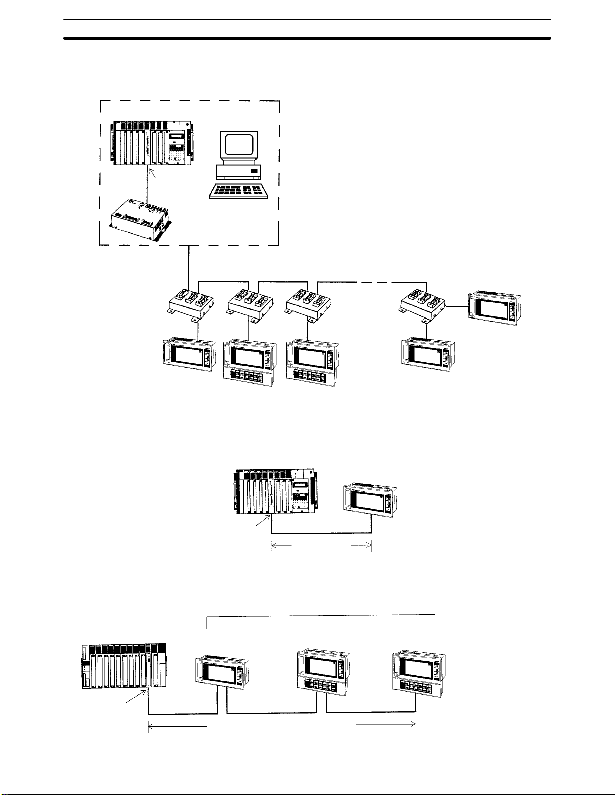
1-6 System Configuration
The Host Interface Unit mounted on the back of the PT is connected to the
host (i.e., a personal computer or Programmable Controller) via communication cable. The PT must be used with a Host Interface Unit. If no Host Interface Unit is mounted, the PT will not operate. Refer to the NT-series Host
Interface Unit Operation Manual for details on connecting between the Host
Interface Unit and the host.
Using the N600M-LK201 Host Interface Unit, the Programmable Terminal
can be connected one-to-one to a PC through an ASCII Unit, or to personal
computer.
C200H, C500, C1000H,
or C2000H PC
15 m max.
RS-232C
ASCII Unit
RS-232C
15 m max.
NT20M/NT2000M
with NT600M-LK201
Personal computer
NT20M/NT2000M
with NT600M-LK201
RS-232C Interface
(NT600M-LK201)
System Configuration Section 1-6
Page 15
7
Using NT600M-LK202 Host Interface Units, up to 16 NT20M or NT2000M
Programmable Terminals can be connected to a PC through an ASCII Unit,
or to an FA computer.
(16 Terminals max.)
C-series PC
ASCII Unit
(RS-232C)
3G2A9-AL004-(P)E
Link Adapter
Cable length: 500 m max.
Branch lines: 10 m max. each.
RS-422
3G2A9-AL001
Link Adapters
NT20M or NT2000M
with NT600M-LK202
FA computer
NT20M or NT2000M
with NT600M-LK202
Using the NT600M-LK201 Host Interface Unit and RS-232C cable, the Programmable Terminal can be connected one-to-one to a PC through a Host
Link Unit.
Host Link Unit
C200H or C500 PC
RS-232C
15 m max.
NT20M or NT2000M
with NT600M-LK201
Using NT600M-RT121 Host Interface Units, up to 8 Programmable Terminals
can be connected to a PC through a Wired Remote I/O Master Unit.
Remote I/O
Master Unit
200 m max. (2-wire cable)
C200H, C500, C1000H, or
C2000H PC
8 Terminals max.
NT20M or NT2000M
with NT600M-RT121
RS-422 Interface
(NT600M-LK202)
Host Link Unit Interface
(NT600M-LK201)
Wired SYSMAC BUS
Interface
(NT600M-RT121)
System Configuration Section 1-6
Page 16

8
With the C200H Host Interface Units, the interface is set up simply by connecting with cable to the C200H CPU Rack or Expansion I/O Rack. It is also
possible to connect to C20H, C28H, C40H, and C60H CPU Units or I/O
Units. Be sure to use a noise filter when connecting CjjH. Refer to the
Host Interface Units Operation Manual for details.
In a C200H PC System, you can ordinarily connect two Expansion I/O Racks to
the CPU Rack. The C200H Host Interface Unit itself, however, functions as an
Expansion I/O Rack, and therefore when using a C200H Host Interface Unit, you
can only connect one other Expansion I/O Rack.
C200H CPU Rack
C200H Expansion I/O Rack
NT20M or NT2000M
with
NT600M-LB121
C200H-CN221
Connection Cable
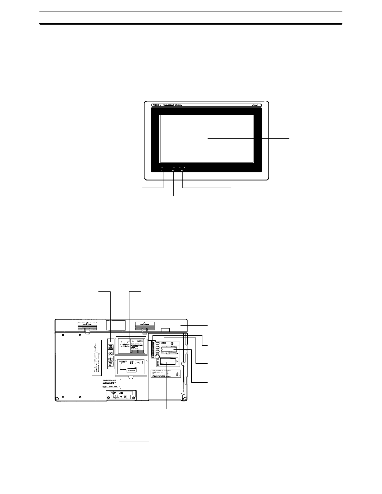
1-7 Nomenclature and Functions
1-7-1 NT20M-Dj121-V2/Dj13j
Front Panel
Display
POWER Indicator (green)
Lit while power is on.
RUN Indicator (green)
Lit during operation
System Keys
Used when maintenance of the
NT20M, selecting the System
Menu, etc. Used during operation
for scrolling the screen and inputting numeric values.
BAT LOW Indicator (red)
Lights if the lithium
battery voltage level
drops.
Peripheral Device Interface
Drip-proof Cover
Drip-proof Cover Screw
To ensure drip-proof protection,
tighten this screw securely.
Display
Note If there are is no battery installed, the BAT LOW indicator will light.
C200H Host Interface
(NT600M-LB121)
Nomenclature and Functions Section 1-7
Page 17

9
Bottom
Extended I/O Unit Connector
(NT20M-DNjjj only)
Remove seal when connecting
a 12-key Function Key Unit.
Components under Drip-Proof Cover
NT20M-Dj121-V2
The illustration below is for the NT20M-Dj121-V2. The NT20M-Dj13j is
basically similar except for the contrast control being in a slightly different
position.
Reset Switch
Pressing this switch initializes
the NT20M. The status of
screen data before initialization is retained.
Peripheral Device Connector
Used to transfer screen data
between the Support Tool and
the NT20M.
Contrast Control
Adjusts display contrast.
Turning clockwise increases contrast.
Note When adjusting the contrast,
use the screwdriver included
with the drip-proof cover.
Rear Panel
Lithium Battery Cover
The lithium battery is
under this cover.
Cover for 8-position DIP switch for system settings
Slide switch for memory
settings (SW2)
Socket with lever, for installing
image data memory
Connector for Host Interface Unit
Terminal block cover
(Refer to 2-5 Wiring and Connectors)
Socket for mounting System ROM
(NT20M-SMRjj)
Nomenclature and Functions Section 1-7
Page 18
10
1-7-2 NT2000M-Dj131
Front Panel
POWER Indicator (Green)
Normally lit when power is
turned on.
BAT LOW Indicator (Red)
Lights when the voltage level
of the lithium battery drops.
RUN Indicator (Green)
Lit during operation.
Display
Note When no battery is installed, BAT LOW indicator operation is unstable.
Rear Panel
System Keys Connector Cover
The RS-232C interface connector
and the battery are located under
this cover.
Backlight Cover
The backlight is located under this cover. To
open the cover, push and slide upwards.
Host Interface Connector
Connects to the Host Interface Unit.
Slide Switch for Setting
Memory (SW2)
Socket With Lever for Installing Screen
Data Memory
The image data memory chip is installed
here.
Socket for Installing System ROM
The System ROM is installed here.
Terminal Block
Switch Cover
Switches are located
under this cover.
Nomenclature and Functions Section 1-7
Page 19

11
Components Under the Connector Cover
Peripheral Device
Interface Connector
Transfers image data
between the
NT2000M and a peripheral device.
Buzzer Sound Enable/Disable Pin
When this pin is pulled out, the buzzer will not
sound under any conditions. When the circuit
is closed, the buzzer will sound in accordance
with the system.
Lithium battery
Components Under the Switch Cover
8-pin DIP Switch for System Settings
Contrast Control
Adjusts display contrast. Sliding to the
right increases contrast.
Reset Switch
Pressing this switch initializes
the NT2000M. The status of
screen data before initialization is retained.
System Key Unit
When using the System Key
Unit, remove the short-circuit
socket.
External System Key Connector
This connector enables the system keys to be used externally.
Nomenclature and Functions Section 1-7
Page 20

13
SECTION 2
Settings and Installation
This section provides procedures to set hardware switches and install the PT.
2-1 Switch Settings 14. . . . . . . . . . . . . . . . . . . . . . . . . . . . . . . . . . . . . . . . . . . . . . . . . . . . . . . . . . .
2-1-1 System DIP Switch Settings (SW1) 14. . . . . . . . . . . . . . . . . . . . . . . . . . . . . . . . . . .
2-1-2 System ROM Mounting 15. . . . . . . . . . . . . . . . . . . . . . . . . . . . . . . . . . . . . . . . . . . . .
2-1-3 Memory Setting (SW2) 15. . . . . . . . . . . . . . . . . . . . . . . . . . . . . . . . . . . . . . . . . . . . .
2-1-4 Inserting the Screen Data Memory 15. . . . . . . . . . . . . . . . . . . . . . . . . . . . . . . . . . . .
2-2 Installation Environment 16. . . . . . . . . . . . . . . . . . . . . . . . . . . . . . . . . . . . . . . . . . . . . . . . . . .
2-2-1 Installation Site 16. . . . . . . . . . . . . . . . . . . . . . . . . . . . . . . . . . . . . . . . . . . . . . . . . . .
2-2-2 Mounting Position 16. . . . . . . . . . . . . . . . . . . . . . . . . . . . . . . . . . . . . . . . . . . . . . . . .
2-3 Dimensions 17. . . . . . . . . . . . . . . . . . . . . . . . . . . . . . . . . . . . . . . . . . . . . . . . . . . . . . . . . . . . . .
2-3-1 NT20M Programmable Terminals 17. . . . . . . . . . . . . . . . . . . . . . . . . . . . . . . . . . . . .
2-3-2 NT2000M Programmable Terminals 18. . . . . . . . . . . . . . . . . . . . . . . . . . . . . . . . . . .
2-4 Installing in a Panel 18. . . . . . . . . . . . . . . . . . . . . . . . . . . . . . . . . . . . . . . . . . . . . . . . . . . . . . .
2-5 Wiring and Connectors 21. . . . . . . . . . . . . . . . . . . . . . . . . . . . . . . . . . . . . . . . . . . . . . . . . . . . .
2-5-1 Terminal Block 21. . . . . . . . . . . . . . . . . . . . . . . . . . . . . . . . . . . . . . . . . . . . . . . . . . .
2-5-2 Power Supply and Battery Wiring 22. . . . . . . . . . . . . . . . . . . . . . . . . . . . . . . . . . . . .
2-5-3 LG and GR Terminals 23. . . . . . . . . . . . . . . . . . . . . . . . . . . . . . . . . . . . . . . . . . . . . .
2-5-4 HOST RUN INPUT Terminal 24. . . . . . . . . . . . . . . . . . . . . . . . . . . . . . . . . . . . . . . .
2-5-5 ALM OUTPUT (Alarm Output) 25. . . . . . . . . . . . . . . . . . . . . . . . . . . . . . . . . . . . . .
2-6 RS-232C Interface Connector 26. . . . . . . . . . . . . . . . . . . . . . . . . . . . . . . . . . . . . . . . . . . . . . .
2-7 Mounting Function Key Units (to DN-type PT s) 27. . . . . . . . . . . . . . . . . . . . . . . . . . . . . . . . .
Page 21

14
2-1 Switch Settings
There are switches to set under the switch cover on the back of the Terminal,
and also on each Host Interface Unit. For Host Interface Unit switch settings,
refer to the Host Interface Unit Operation Manual. Be sure to set the switches
before installation if the installation location prevents access to the switches
after installation.
2-1-1 System DIP Switch Settings (SW1)
The 8-pin DIP switch for system settings is located under the DIP switch cover on the back of the Terminal. Be sure that power is off when changing
switch settings.
ON
SW1
12345678
Communications specification
(only for when NT600M-LK201 is mounted)
ON: Host Link
OFF: RS-232C
Not used.
Reserved (Always ON).
Mode change enable/disable
ON: Enable
OFF: Disable
HOST RUN input enable/disable
ON: Disable
OFF: Enable
Automatic reset after communications error
ON: No automatic reset.
OFF: Automatic reset.
Not used.
Bit designation for lamps/touch switches
ON: 0 to 63
OFF: 0 to 111
Automatic reset after
communications error
“Automatic reset” means that, when an error occurs, no error message will be displayed and
the next command will be executed when received. “No Automatic reset” means that, when
an error occurs, an error message will be displayed and operation will stop.
HOST RUN input
enable/disable
If this pin is turned OFF then, when the HOST RUN INPUT turns OFF, Host Error will be
displayed regardless of other conditions and processing will stop.
Bit designation for lamps
and touch switches
This pin designates the bits for lamp and touch switch display control for when Host Link
Interface Units, C200H Host Interface Units are used.
Mode change
enable/disable
“Mode change” refers to changing between the System Menu and Transmit Mode,
Maintenance Mode, or RUN Mode. When an RS-232C or RS-422 Host Interface Unit is
used, mode changes can be prohibited by means of a command from the host.
Communications
specification
When an NT600M-LK201 Host Link Unit is used, the communications specification must be
set to either Host Link or RS-232C. If the PC setting and the Host Interface Unit setting do
not match, operation will not be possible.
Pin 3
Pin 3 is factory-set to OFF and must be turned ON by the user. Screens will not be displayed
properly unless this pin is ON.
Switch Settings Section 2-1
Page 22

15
2-1-2 System ROM Mounting
1, 2, 3... 1. Turn off the power to the PT.
2. Set the groove of the mounting screw on the right edge of the IC socket to O
(Open).
3. Mount th e System ROM in the direction of the seal on the IC socket and set
the groove of the mounting screw to C (Close) to lock the System ROM.
IC socket
Seal
Mounting screw
4. Make sure that the groove of the mounting screw is set to C, otherwise the
System ROM will not be locked.
Socket
The groove is
improperly set
Note 1. Be sure to turn off the PT when mounting or dismounting the System
ROM to the IC socket, otherwise the internal memory of the PT may be
damaged.
2. Be sure to lock the System ROM after mounting, otherwise the operation
of the PT will be unstable.
3. OMRON Corporation has the copyright of the System ROM program.
Making a copy of the program is prohibited without the prior consent of
the OMRON Corporation.
2-1-3 Memory Setting (SW2)
This switch is used to set the type of data memory to be installed in the socket at the back of the Terminal.
SW2
The switch is factory-set
to the left, as shown here.
SW 2
Screen data memory
Left SRAM
Right EPROM
Center EEPROM
Note 1. Be sure that the power is off when changing the setting.
2. Carefully check the switch settings and the memory chip before turning
the power on. If memory is not installed in accordance with this switch
setting, the Terminal will not operate properly and memory may be destroyed.
2-1-4 Inserting the Screen Data Memory
1, 2, 3... 1. Turn off the power to the PT.
2. Set switch 2 to match the memory chip that is to be inserted.
Switch Settings Section 2-1
Page 23

16
3. Raise the IC socket lever, and insert the memory chip in the direction indicated on the seal. The chip will have either 28 or 32 pins. Line it up with the
position shown on the seal.
4. Check t o be sure that the memory chip is inserted securely, and then lock the
lever back into place.
Note Be sure to turn the power off before removing the memory chip.
2-2 Installation Environment
The NT20M and NT2000M PTs have strong environmental resistance and
high reliability, but you can maximize system reliability and make the most of
their functions by observing the following considerations during installation.
2-2-1 Installation Site
Avoid installing the PT in a location where any of the following conditions exist.
• Ambient temperatures exceeding a range of 0°C to 45°C for the NT20M or
0°C to 50°C for the NT2000M.
• Abrupt temperature changes or condensation.
• Relative humidity exceeding a range of 35% to 85%.
• Corrosive or inflammable gasses.
• Strong magnetism.
• Excessive dust, salt, or iron dust.
• Direct vibration or shock.
• Direct sunlight.
• Spray from water, oil, or chemicals (even though the front panel of the
NT20M is drip-proof and the entire NT2000M is waterproof).
2-2-2 Mounting Position
The PT employs a liquid crystal display, so the angle of vision should be considered when mounting. Install the Terminal at a height and direction that
make it easy for the operator to see.
Ambient Temperature The ambient operating temperature range is 0°C to 45°C for the NT20M and
0°C to 50°C for the NT2000M. Take the following factors into consideration.
• Leave sufficient ventilation space.
• Do not install directly above machinery that radiates a lot of heat (e.g.,
heaters, transformers, high-capacity resistors).
• If the ambient temperature rises above 45°C, set up a fan or air conditioner.
PT
Control panel
Fan
Louver
Operation and Maintenance For safety during operation and maintenance, place the PT as far as possible
from high-voltage machinery and power equipment.
Installation Environment Section 2-2
Page 24

17
Improving Noise Resistance Do not install the PT in a panel with high-voltage devices, and install it at
least 200 mm from electric power lines.
PT
200 mm min.
200 mm min.
Power line
When installing the Terminal near devices with strong electrical or magnetic
fields (such as solenoids), allow a distance of at least 40 mm, more if necessary.
PT
40 mm min.
40 mm min.
Solenoid
Solenoid
2-3 Dimensions
All dimensions are in millimeters.
2-3-1 NT20M Programmable Terminals
Terminals With and Without Touch Panels
208
220
110
98
4.5
82
Cable
40
Approx.
80
Dimensions Section 2-3
Page 25

18
Terminals With Function Keys
An NT20M-FK210 12-key Function Key Unit can be connected to PTs without
touch panels (i.e., DN type PTs).
208
220
164
4.5
49
82
152
98
Cable
Approx.
80
40
2-3-2 NT2000M Programmable Terminals
NT2000M-DN131
351
365
232.5 218.5
76.8
12
Cable
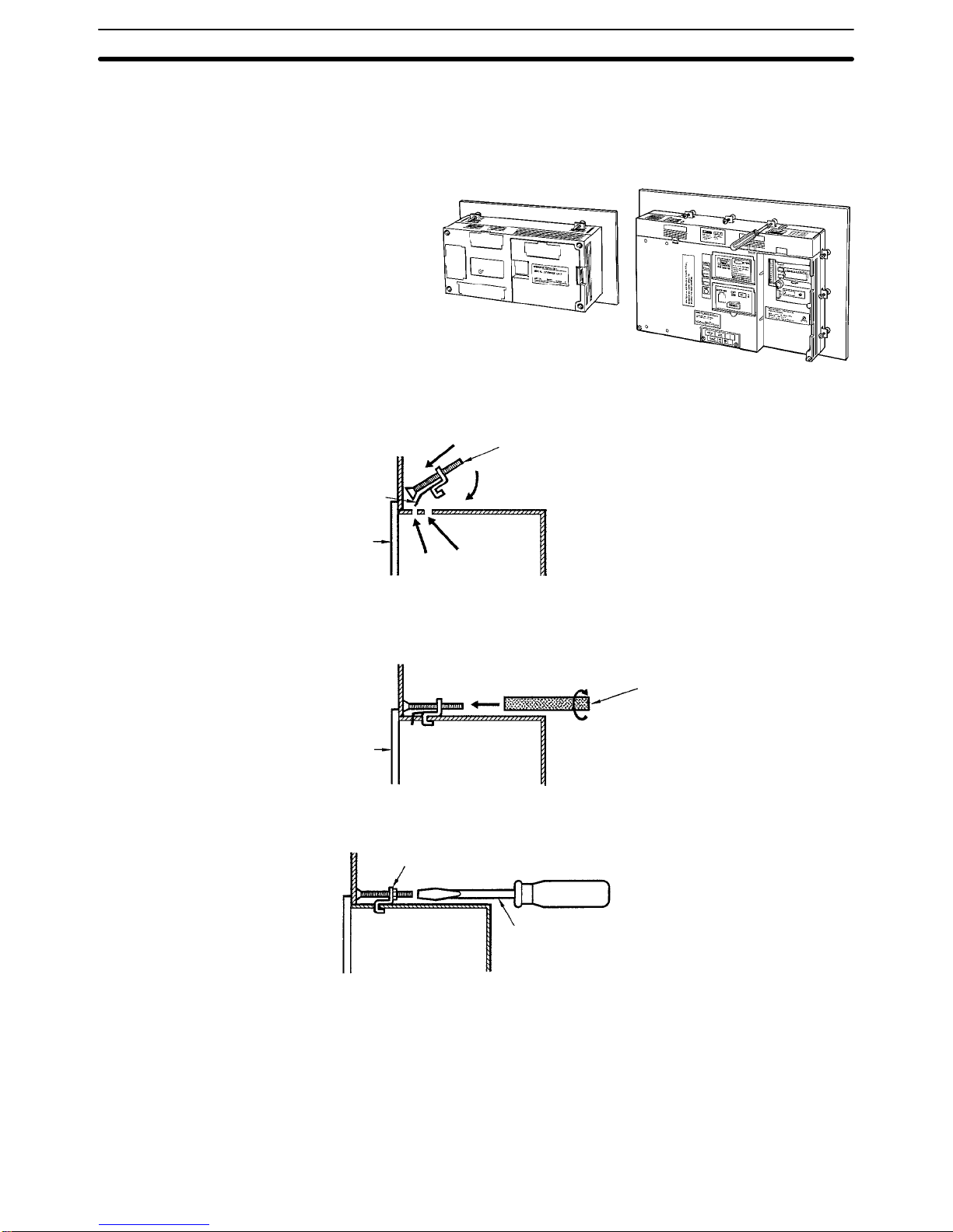
2-4 Installing in a Panel
The NT20M is designed to be installed in a panel. Install it as follows:
1, 2, 3... 1. Cut a hole in the panel in accordance with the recommended dimen-
sions shown below. The panel should be between 1.6 and 4.8 mm thick.
For PTs that have the backlight replaced from the side (i.e., NT20M-DT/
Installing in a Panel Section 2-4
Page 26

19
DN131), however, the panel should only be from 1.6 to 2.0 mm thick, in
order to allow enough space to replace the backlight.
Side Space for Backlight Replacement:
When mounting the NT20M to a panel, leave open the space marked
with dotted lines on the left of the rear panel as shown below.
175 mm min.
20 mm min.
NT2000M PTs have the backlight replaced from the back, so they need
not be accessed from the side. All dimensions shown below are in millimeters.
NT20M-Dj121-V2 NT20M-DN121-V2 with NT20M-FK210
NT20M-Dj131 NT20M-DN131 with NT20M-FK210
Installation
space
98.5
+0.5
–0
209±0.5
Installation
space
209±0.5
153 0.5+
NT2000M-DN131
Installation
space
219
+0.5
–0
351
+0.5
–0
2. Insert the Terminal into the hole from the front of the panel.
NT20M NT2000M
Installing in a Panel Section 2-4
Page 27
20
3. Use the accessory metal fittings and tool to fasten the Terminal to the
panel surface. Do not use a screwdriver on the fittings, otherwise the
fittings or the terminal of the NT20M may become damaged.
NT20M NT2000M
Securing the NT20M to the Panel
After setting the NT20M into the panel, secure it as shown below.
(1) First pass the plastic part of the
fitting through slot (a).
(2) Next, put the hook of the fitting
into slot (b) and pull so that the
leg catches in the NT20M case.
NT20M
Fitting
Plastic
(1)
(2)
(b)
(a)
Turn the screw with the tool that comes with the NT20M, and secure the
NT20M to the panel. When you are finished, rotate the tool in the reverse direction and remove it from the screw.
NT20M
Accessory tool
4. To remove the NT20M from the panel, use a flat-blade screwdriver. (For
the NT2000M, use a Phillips screwdriver.)
4 panel installation fittings
Flat-blade screwdriver
Securing the NT2000M to the Panel
Using the tool that comes with the NT2000M, secure the NT2000M to the
panel from behind. When not making it waterproof, the four places marked
“A” in the illustration below must not be tightened. Use a tightening torque of
no more than 6 kg.
When making the NT2000M waterproof, tighten all twelve places shown in
the illustration, including the places marked “A.” Use a tightening torque of at
least 8 kg and no more than 10 kg.
Installing in a Panel Section 2-4
Page 28

21
To remove the NT2000M from the panel, use a Phillips screwdriver.
Phillips screwdriver
View from rear
A
A
AA
2-5 Wiring and Connectors
2-5-1 Terminal Block
The terminal blocks illustrated below are located under the respective terminal block covers of the NT20M and the NT2000M.
NT20M
10
10
1.4
3
ALM
OUTPUT
HOST
RUN
INPUT
24 VDC
Terminal screws: M3.5
+
Dimensions are in millimeters.
NT2000M
HOST
RUN
INPUT
ALARM
OUTPUT
LG GR100 to 240 VAC
50/60 Hz
Terminal screws: M4
Crimp-style Terminals for Wiring
Use crimp-style terminals for wiring. If twisted wires are connected directly,
there is a possibility of poor contact or short-circuiting. For the NT20M, use
crimp-style terminals with holes to match M3.5 screws. For the NT2000M,
use crimp-style terminals with holes to match M4 screws. The dimensions
shown in the illustration below are for the NT20M. For the NT2000M, the dimensions would be 8.6 mm max. for both the fork-type and the round-type.
7 mm max.
Fork-type
8 mm max.
Round-type
Wiring and Connectors Section 2-5
Page 29

22
Conforming Crimp-style Terminals
Maker Fork-type
(NT20M)
Round-type
(NT20M)
Fork-type
(NT2000M)
Round-type
(NT2000M)
Conforming wire (twisted)
Japan Solderless Terminal MFG 2-YS3A 2-3.5 2-4A 2-4 1.04 to 2.63 mm
2
Fuji Terminals 2-YAS3.5 V2-S3.5 2-YA4 V2-4
Nichifu Terminals 2Y-3.5 2-3.5 2Y-4 2-4
2-5-2 Power Supply and Battery Wiring
24 VDC (NT20M)
These are the power supply input terminals for running the NT20M.
Breaker
24-VDC
power supply
+
NT20M Power Supply Wiring
• Provide 24-VDC power.
• Use a power supply within the allowable voltage range.
Power supply voltage Allowable voltage range
24 VDC 20.4 to 26.4 VDC
• Use a power supply with a rated capacity of at least 15 W at 24 VDC.
• If power lines are long, then use wires of at least 2 mm
2
to avoid a drop in
voltage.
• Use twisted-pair cables.
• Turn off the power before wiring.
• Be careful not to reverse the positive and negative terminals.
• Do not run the wiring between the 24-VDC power supply and the PT power
supply input terminal parallel to or in close proximity with high-voltage or
high-current power lines.
• If you anticipate noise levels exceeding specifications, use noise-prevention
measures such as installing a noise filter at the power supply. Use a common mode filter as the noise filter, and install no more than 100 mm of wiring from the PT to the filter.
• If you use a 24-VDC power supply with no output short-circuit prevention,
then wire a breaker into the circuit.
Wiring and Connectors Section 2-5
Page 30

23
AC Input (NT2000M)
These are the power supply input terminals for running the NT2000M.
MCCB
100 to 240 VAC
50/60 Hz
Insulated
transformer
NT2000M Power Supply Wiring
• Provide a 100 to 240 VAC power.
• Use a power supply within the allowable voltage range.
Power supply voltage Allowable voltage range
100 to 240 VAC 85 to 264 V AC
• Insulated Transformer
The NT2000M has built-in anti-noise features which are sufficient for handling general noise from power lines, but ground noise can be greatly reduced by supplying power through a 1:1 insulated transformer. The secondary side of the insulated transformer should be an isolated neutral system.
• Power Capacity
Use a rated power supply of at least 50 VA.
• If power lines are long, then use wires of at least 2 mm
2
to avoid a drop in
voltage.
• Use twisted-pair cables.
2-5-3 LG and GR Terminals
HOST
RUN
INPUT
ALARM
OUTPUT
100 to 240 VAC
50/60 Hz
LG GR
Terminal screws are M4.
• GR is the ground terminal. In order to avoid electric shock, use separate
ground wire (at least 2 mm
2
) and a class-3 ground (ground resistance
100 W or less).
• LG is the noise filter neutral terminal. If malfunction results from excessive
noise, or to prevent electrical shock, short-circuit LG and GR and use a
class-3 dedicated ground.
• The ground line should be 20 m or less.
Wiring and Connectors Section 2-5
Page 31
24
• Sharing a ground line with other machinery or grounding to the girders of a
building may be ineffective and even harmful.
Other
machinery
Class-3
ground
NT2000M
LG GR
NT2000M
LG GR
Other
machinery
Okay No
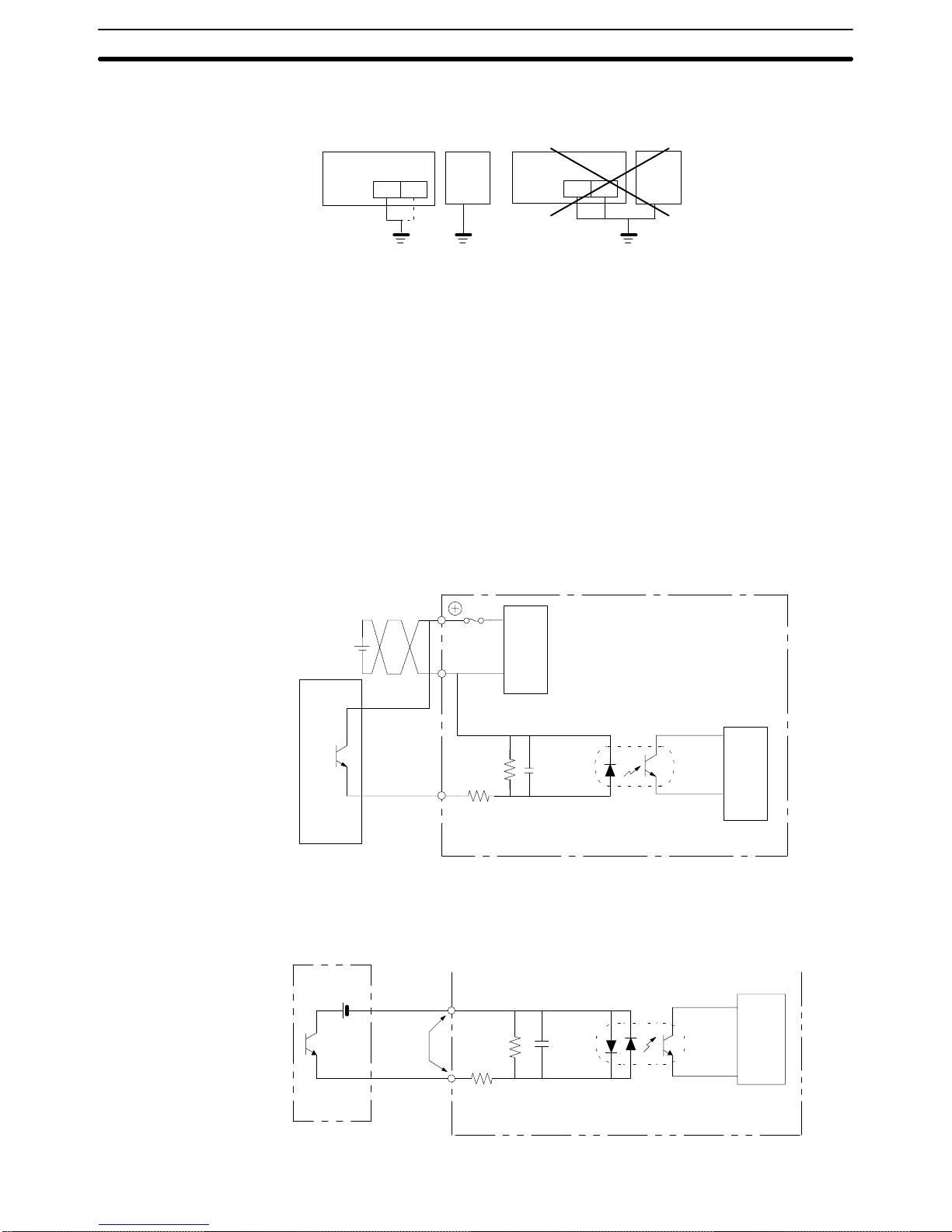
2-5-4 HOST RUN INPUT Terminal
Use the HOST RUN INPUT when you want to monitor the RUN status of the
host. When this input terminal is enabled by pin 2 of DIP switch 1, then, if the
HOST RUN INPUT turns OFF, PT processing will be interrupted and a priority message will be displayed indicating that a host error has occurred. This
condition will be maintained until the host RUN status is restored.
Enable: Turn OFF SW1, pin 2.
Disable: Turn ON SW1, pin 2.
NT20M
1000 pF
NT20M
620 Ω
5.6 kΩ
HOST RUN
INPUT
24 VDC
Host
Host RUN status with
transistor ON.
Internal circuit
Power supply
circuit
NT2000M
HOST
RUN
INPUT
Host
Host RUN status
with transistor ON.
(This terminal has no polarity.)
620 Ω
5.6 kΩ
1,000 PF
Internal circuit
Wiring and Connectors Section 2-5
Page 32

25
Input Specifications (For Both NT20M and NT2000M)
Item Content
Rated input voltage 24 VDC
+10%
/
–15%
Input impedance 5.6 kΩ
Input current 4.1 mA typical (at 24 VDC)
ON voltage 15.5 V min.
OFF voltage 5.0 V max.
ON delay 2.5 ms max.
OFF delay 2.5 ms max.
Insulation method Photocoupler
2-5-5 ALM OUTPUT (Alarm Output)
This terminal outputs the PT alarm signal. Use this terminal when you want
to externally monitor status.
NT20M
Load
24 VDC
ALM
OUTPUT
External device
Internal circuit
Internal circuit
Item Content
Output type Relay output
Rated load 24 VDC
+10%
/
–15%
Maximum load current 1 A
Minimum switching capacity 10 mA at 5 VDC
Leakage current 0.1 mA max.
Residual current 1.0 V max.
ON delay 2.5 ms max.
OFF delay 2.5 ms max.
Wiring and Connectors Section 2-5
Page 33

26
NT2000M
External device
Load
ALM output
Internal circuit
100 to 240 VAC input
Item
Content
Output type Relay output
Rated load 1 A at 24 VDC
Maximum load current 1 A
Minimum switching capacity 10 mA at 5 VDC
2-6 RS-232C Interface Connector
The RS-232C interface connector is used during communications between
the PT and the Support Tool. It is located under the RS-232C interface connector cover on the front of the NT20M or NT2000M.
Pin Allocation
Pin no. Symbol Name
1 FG Frame Ground (not used)
2 SD Send Data
3 RD Receive Data
4 RS Request to Send
5 CS Clear to Send
9 SG Signal Ground
Connection Diagram
SD
RD
RS
CS
SG
FG
SD
RD
RS
CS
SG
FG (Not connected.)
1
2
3
4
5
7
2
3
4
5
1
9
Personal computer
(25 pins)
Shielded wire
D-sub connector, 9 pins
RS-232C PT
Note 1. RS-232C communications conditions are set automatically by the NT20M
Support Tool.
2. Connectors can be connected and disconnected with power turned on.
3. This connection diagram cannot be used for the Host Interface Unit.
RS-232C Interface Connector Section 2-6
Page 34

27
Plug: XM2A-0901 (OMRON) or equivalent.
Hood: XM2S-0911 (OMRON) or equivalent.
Recommended Cables AWG 28 x 5P IFVV-SB (Fujikura Cable, Ltd.)
CO-MA-VV -SB 5P x 28 AWG (Hitachi Cable, Ltd.)
Cable Set CV500-CN228 (OMRON)
Cable length: 2 m
2-7 Mounting Function Key Units (to DN-type PTs)
Mounting Procedure
1, 2, 3... 1. Remove the rubber packing and bottom connector seal from the DN-type
PT.
2. Mount t h e 1 2 - k e y F u nction Key Unit to the PT, matching the connectors. Using a Phillips screwdriver, tighten the five mounting screws.
NT20M-DNjjj
Programmable Terminal
Phillips screwdriver
NT20M-FK210 12-key
Function Key Unit
Mounting screws (5 places)
3. Attach the rubber packing that comes with the 12-key Function Key Unit.
Rubber packing
4. Mount to the panel.
Applicable Connectors
(Cable Side)
Mounting Function Key Units (to DN-type PTs)
Section 2-7
Page 35

29
SECTION 3
Initial Operation
This section provides an introduction to the operations necessary to use a PT for the first time and to the menus and keys
used to control PT operation.
3-1 Powering Up 30. . . . . . . . . . . . . . . . . . . . . . . . . . . . . . . . . . . . . . . . . . . . . . . . . . . . . . . . . . . . .
3-2 Initialization 30. . . . . . . . . . . . . . . . . . . . . . . . . . . . . . . . . . . . . . . . . . . . . . . . . . . . . . . . . . . . .
3-2-1 Initializing Memory 30. . . . . . . . . . . . . . . . . . . . . . . . . . . . . . . . . . . . . . . . . . . . . . . .
3-2-2 Menus 31. . . . . . . . . . . . . . . . . . . . . . . . . . . . . . . . . . . . . . . . . . . . . . . . . . . . . . . . . . .
3-3 Transferring Data to and from the Support Tool 32. . . . . . . . . . . . . . . . . . . . . . . . . . . . . . . . .
3-4 Initial Settings 33. . . . . . . . . . . . . . . . . . . . . . . . . . . . . . . . . . . . . . . . . . . . . . . . . . . . . . . . . . .
Page 36

30
3-1 Powering Up
When first starting up the system, do not connect the Host Interface Unit to
the host. When power is turned on to the PT, either a “Connecting to host”
message or the initial screen set by the Support Tool will be displayed. The
“Connecting to host” message will be displayed if a Host Link Interface Unit,
a SYSMAC BUS Interface Unit, or a C200H Host Interface Unit is mounted.
The initial screen will be displayed if an RS-232C/RS-422 Interface Unit is
mounted.
If there is no image data registered for the PT, or if there is an error in the
image data that is registered, then the System Menu will be displayed
instead, with an error message at the bottom. In that case, it will be necessary to initialize the memory and transmit the correct data.
3-2 Initialization
Initialize the memory in the PT using the procedure described below. This
procedure can also be used later to completely delete data from the PT. Always be careful not to initialize and delete essential data.
3-2-1 Initializing Memory
Perform the initialization if the screen memory is either SRAM or EEPROM.
Check to be sure that the screen memory is installed.
Memory initialization can be used to initialize screen memory, memory tables,
and history data. Initializing screen memory completely deletes the contents
of the screen memory, including the contents of numeral tables and text
string memory tables. Initializing memory tables overwrites numeral tables
and text string memory tables with the initial values set by the Support Tool.
Initializing the display history deletes all of the display history data.
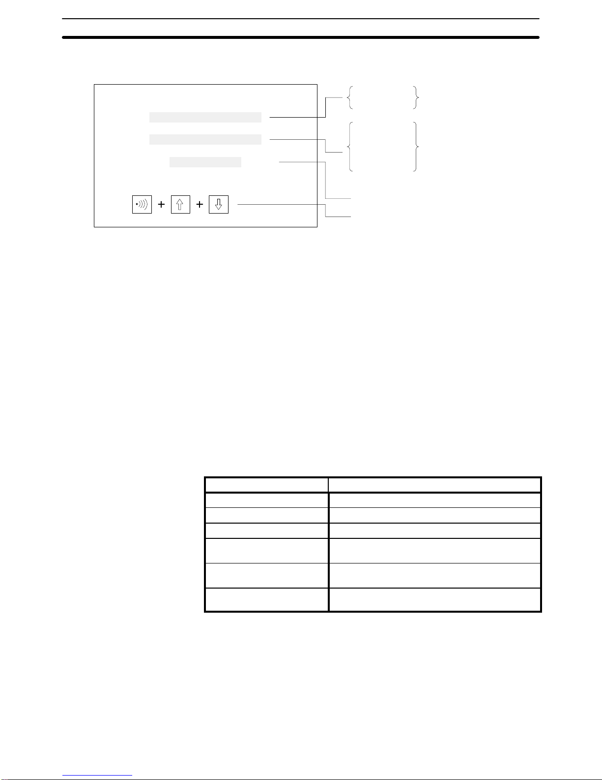
To initialize the screen memory, first access the system menu by simultaneously pressing the Buzzer Key, Up Key, and Down Key. Then proceed as
shown below.
System Menu
Select “MAINTENANCE MODE.”
Select “Init. Screen.”
Initialize Screen Memory?
No
Yes
Refer to Section 6 System Menu.
If you select yes, then memory will be initialized and all data used for displays
will be erased. After initialization, operation will begin.
Initialization Section 3-1
Page 37

31
If you select no, then operation will begin without initialization.
When entering RUN Mode after initialization, nothing will be displayed on the
screen and the Terminal will wait for a command from the host.
Caution Screen memory must be initialized before using a new PT. If the PT is used
as shipped from the factory without initialization, messages indicating errors
in the host will not be displayed properly.
3-2-2 Menus
The System Menu is called up by using the system keys during operation.
Transmit Mode
Maintenance Mode
SYSTEM MENU
Quit
Using System Keys
Operation Content
Press the Buzzer Key, Up Key,
and Down Key simultaneously.
The System Menu shown above is displayed during operation. If actions are executed
while the System Menu is being displayed, the system returns to operation. With the
Buzzer Key pushed down, press the Up Key and Down Key simultaneously.
Press the Up Key. Moves the bar cursor upward.
Press the Down Key. Moves the bar cursor downward.
Press the Enter Key. Selects the menu at the position of the bar cursor.
Quit Use either of the following two methods to leave the System Menu and return
to operation.
1, 2, 3... 1. Select “Quit.”
OR
2. Press the Buzzer Key, Up Key, and Down Key simultaneously.
In addition, if there are no key inputs within 10 s of calling up the System
Menu, the system will automatically return to normal operation.
Selecting Items To select an item, move the cursor to that item and press the Enter Key.
Selected item Function
Quit Quits and return to normal operation.
Transmit Mode Shifts to Transmit Mode.
Select when transferring data between the PT and Support Tool. For details, refer to 3-3
Transferring Data to and from the Support Tool.
Maintenance Mode Shifts to Maintenance Mode.
Used to check the setting status of the PT and conducts self-testing.
Initialization Section 3-1
Page 38

32
Error Messages When there is an error in screen data registered in the PT, the System Menu
will appear before entering RUN Mode, and the error message will be displayed on the bottom line.
Transmit Mode
Maintenance Mode
System Menu
Quit
Screen Data Corrupted Example of error message
There are three types of error messages, as shown below. Operation will not
begin again until the error has been corrected.
Error message Error Content and Correction
Screen Data Corrupted This is displayed when registered screen data is corrupted. Initialize the screen data and
re-register the screen data. Operation will not begin again until the data is restored.
Mark Data Corrupted This is displayed when registered mark data is corrupted. Initialize the screen data and
transfer the screen data files. The mark data is included in the screen data files. Re-register
the mark data. Operation will not begin again until the data is restored.
Memory Not Formatted This is displayed when the screen data area is not formatted. Initialize the screen data
memory. All registered screen data, mark data, and system data will be deleted by the
initialization, so they will have to be transferred again from the Support Tool. In addition, if
the image data memory is the IC socket type, recheck the socket memory and its settings.
3-3 Transferring Data to and from the Support Tool
The following data can be transferred between the PT and the Support Tool.
Data Support Tool to PT PT to Support Tool
Screen data All screens or one screen All screens or one screen
Text string table YES YES
Numeral table YES YES
Mark data YES YES
Display history data None YES
System Memory* (Initial
screen after power-up)
YES YES
Note System Memory is the first (initial) screen after the PT is powered up.
Procedure Use the following procedure to transfer data.
1, 2, 3... 1. Connect the PT and personal computer running the Support Tool.
2. Select Transmit Mode from the System Menu.
System Menu
Select “Transmit Mode.”
Refer to Section 6 System Menu.
Transferring Data to and from the Support Tool Section 3-3
- - - - - - - - - - - - - - -
Page 39
33
3. Perform the transfer operation from the Support Tool. The screen shown
below will be displayed during the transfer.
Abort:
Transmit Mode
KB
PT --> Host
Host --> PT
Screen Data
System Memory
Memory Tables
Mark Data
History Data
Number of bytes transferred (in kilobytes).
Press these three System Keys simulta-
neously to stop the transfer in progress.
Shows direction
of data transfer.
Shows type of data.
4. In the event of a disconnected cable or other disruption while the transfer is in progress, the PT screen will go blank and a message telling you
that transfer was not possible will be displayed at the Support Tool. If the
transfer is completed successfully, then at the end of the transfer the PT
screen will go blank and a message telling you that the transfer has
been completed will be displayed at the Support Tool.
5. To return from Transmit Mode to RUN Mode, press the Buzzer Key, Up
Key, and Down Key simultaneously.
Note After completion of the transfer, be sure to change to Maintenance Mode. If
power is turned off or the reset switch is pressed before changing to Maintenance Mode, the data that is transferred will be damaged.
When using the EEPROM as a screen data memory, screens cannot be
transferred screen by screen from the Support Tool to the PT. The screen
data must be transferred in file units after initializing the memory.
3-4 Initial Settings
When power is turned on, the PT’s internal status is initialized to the following
settings.
Item Initial value
Character string memory Screen data memory content
Numeral memory Screen data memory content
Lamp/touch switch status OFF
Key Press Sound ON (When a battery is installed, the previously set
value is retained.)
Backlight Off 10 minutes (When battery is installed, the
previously set value is retained.)
Display No display or initial screen (At the Support Tool you
can set either no display or initial screen.)
Initial Settings Section 3-4
Page 40

35
SECTION 4
Display Functions
This section describes the functions used to create screens and control display attributes on the PT. Functions used to input data on-screen are described in Section 5 Input Functions. Data transfer and maintenance functions are described in
Section 6 System Menu. Transferring screens online to and from the host computer is described in Section 7 Online
Transfer.
4-1 Character Displays on Screen 36. . . . . . . . . . . . . . . . . . . . . . . . . . . . . . . . . . . . . . . . . . . . . . .
4-1-1 Types of Characters 36. . . . . . . . . . . . . . . . . . . . . . . . . . . . . . . . . . . . . . . . . . . . . . . .
4-1-2 Designating Display Positions 36. . . . . . . . . . . . . . . . . . . . . . . . . . . . . . . . . . . . . . . .
4-1-3 Character Scale 36. . . . . . . . . . . . . . . . . . . . . . . . . . . . . . . . . . . . . . . . . . . . . . . . . . .
4-1-4 Display Attributes 36. . . . . . . . . . . . . . . . . . . . . . . . . . . . . . . . . . . . . . . . . . . . . . . . .
4-2 Normal Screen Changes 36. . . . . . . . . . . . . . . . . . . . . . . . . . . . . . . . . . . . . . . . . . . . . . . . . . . .
4-2-1 Procedure for Changing Screens 37. . . . . . . . . . . . . . . . . . . . . . . . . . . . . . . . . . . . . .
4-3 Continuous Screens 37. . . . . . . . . . . . . . . . . . . . . . . . . . . . . . . . . . . . . . . . . . . . . . . . . . . . . . .
4-4 Overlapping Screens 38. . . . . . . . . . . . . . . . . . . . . . . . . . . . . . . . . . . . . . . . . . . . . . . . . . . . . .
4-5 Numeric Displays 39. . . . . . . . . . . . . . . . . . . . . . . . . . . . . . . . . . . . . . . . . . . . . . . . . . . . . . . . .
4-6 Character Strings 40. . . . . . . . . . . . . . . . . . . . . . . . . . . . . . . . . . . . . . . . . . . . . . . . . . . . . . . . .
4-7 Bar Graphs 41. . . . . . . . . . . . . . . . . . . . . . . . . . . . . . . . . . . . . . . . . . . . . . . . . . . . . . . . . . . . . .
4-8 Lamps 41. . . . . . . . . . . . . . . . . . . . . . . . . . . . . . . . . . . . . . . . . . . . . . . . . . . . . . . . . . . . . . . . . .
4-9 Graphics Display 42. . . . . . . . . . . . . . . . . . . . . . . . . . . . . . . . . . . . . . . . . . . . . . . . . . . . . . . . .
4-10 Special Controls 42. . . . . . . . . . . . . . . . . . . . . . . . . . . . . . . . . . . . . . . . . . . . . . . . . . . . . . . . . .
4-10-1 Backlight On/Off 42. . . . . . . . . . . . . . . . . . . . . . . . . . . . . . . . . . . . . . . . . . . . . . . . . .
4-10-2 Backlight Red/White 43. . . . . . . . . . . . . . . . . . . . . . . . . . . . . . . . . . . . . . . . . . . . . . .
4-10-3 Buzzer On/Off 43. . . . . . . . . . . . . . . . . . . . . . . . . . . . . . . . . . . . . . . . . . . . . . . . . . . .
4-10-4 Alarm Output On/Off 43. . . . . . . . . . . . . . . . . . . . . . . . . . . . . . . . . . . . . . . . . . . . . . .
4-10-5 HOST RUN INPUT 43. . . . . . . . . . . . . . . . . . . . . . . . . . . . . . . . . . . . . . . . . . . . . . . .
4-10-6 Display History Clear 43. . . . . . . . . . . . . . . . . . . . . . . . . . . . . . . . . . . . . . . . . . . . . .
4-10-7 Terminal Function 44. . . . . . . . . . . . . . . . . . . . . . . . . . . . . . . . . . . . . . . . . . . . . . . . .
Page 41

36
4-1 Character Displays on Screen
The type, size, and attributes of characters that can be displayed on the
NT20M and NT2000M screens are shown below. Character type, size, and
attributes are set at the time of creation on the Support Tool. When an
RS-232C or RS-422 Host Interface Unit is used, coordinates, characters,
etc., can be designated with commands from the host in Terminal Mode.
4-1-1 Types of Characters
Half-size characters (8 x 8 dots) Alphanumeric characters and symbols.
Normal-size characters (8 X 16 dots) Alphanumeric characters and symbols.
Marks (16 X 16 dots) Pictographs defined by the user (up to 64 possible).
4-1-2 Designating Display Positions
The display positions can be designated in increments of display dots. When
characters overlap, characters written last overwrite those written earlier.
4-1-3 Character Scale
It is possible to designate normal, double-width, double-height, 4x, 9x, or 16x
character size. When enlarging by 4x or more, the Programmable Terminal’s
automatic smoothing process (a process that removes the notches from
characters when they are enlarged) makes the characters easier to read.
4-1-4 Display Attributes
Besides the standard display (black characters on a white background), you
can designate individual characters as inverse, blinking, or inverse/blinking.
Blinking Inverse blinking
jj
Note You cannot designate the blinking cycle.
Normal-size
characters
4x characters
Wide
characters
Wide
characters
4x characters
16x characters
4-2 Normal Screen Changes
The displayed screen can be changed to another screen by designating the
screen number from the host (a Programmable Controller or personal com-
Normal Screen Changes Section 4-2
Page 42

37
puter). The designated screen must have already been created at the Support Tool and downloaded to the PT.
4-2-1 Procedure for Changing Screens
1, 2, 3... 1. By designating a screen number (0 to 250) from the host, you can
switch to the designated screen.
2. When an ordinary screen is displayed, the screens cannot be changed
by means of the Up and Down Keys on the front panel of the NT20M.
3. For details on screen-changing procedures for each interface, refer to
the Host Interface Unit Operation Manual.
Note Screen no. 0 is white with no characters.
4-3 Continuous Screens
Screens can be linked to display consecutively, without breaks. A maximum
of eight screens can be made consecutive, and treated as one screen.
Screen
A
B
C
D
A
B
D
20→21→23
Parent screen for consecutive screens
Screen no. 09
Register the screen numbers of the child screens
that you want to make consecutive. (You can set
screen numbers in any order you want.)
Screen contents
20
21
22
23
20
21
23
Screen no. 9: Screens displayed
Example
1, 2, 3... 1. If screen 09 is designated from the host, screen 20 is displayed first.
2. Screens B and D will be displayed in order, either by line or screen scroll
when the Down Key is pressed, depending on the scroll unit setting.
• With line scroll, pressing the Down or Up Key will scroll eight dots at a time.
• With screen scroll, one screen will be scrolled at a time.
• Line and screen scroll are designated by the Support Tool when registering
continuous screens. Screens with variable character string displays, numeric displays, graph displays, touch switches, lamps, or numeric settings cannot be scrolled by line.
Continuous Screens Section 4-3
Page 43

38
• Screens with numeric settings cannot be designated as a child screen for
any consecutive screen.
• A continuous screen cannot be registered as a child screen.
Note The parent screens (screen no. 09 in this case) cannot have screen data.
They can be treated only as parent screens.
4-4 Overlapping Screens
The contents of multiple screens can be laid one on top of another and registered as one screen, when the screens are created on the Support Tool. Just
as with ordinary screens, if the number of a screen registered as an overlapping screen is designated from the host, then the overlapping screens corresponding to that number are displayed.
• A maximum of eight screens may be overlapped.
• Screens with touch switches, lamps, graphs, character strings, and numeric
displays can be overlapped.
• An overlapping screens cannot be registered as a child screen.
Example If screen 02 is designated from the host, then screens 03, 05, and 08 are dis-
played.
Parent screen: Screen no. 02
Overlapping screens
Numbers of child screens:
Note The contents of the screens
are not displayed during setting operations.
Screen no. 03
My name
is
Smith.
Screen no. 02 is designated by the host.
Screen no. 02: Screen displayed
My name is Smith.
Screen no. 05
Screen no. 08
03
05
08
Contents of child screens registered to overlapping screen no. 02:
Note The parent screens (screen 02 in this case) cannot have screen data. They
can be treated only as parent screens.
Overlapping Screens Section 4-4
Page 44

39
4-5 Numeric Displays
A numeral table is stored in the PT, and you can display numeric values from
the table at programmed positions on a screen. In addition, the values in the
table can be transferred from the host so that they are renewed each time a
new value is transferred. The display positions are set in advance with the
Support Tool.
Example
Screen Registered
Production
Line 1
Weld
Assem
No.
Contents
These contents are transmitted from the host.
When the PC is used as the host, for example, these values will be transferred via the Host
Interface Unit and updated on screen when the contents of the DM Area are changed.
Final
Paint
Line 2
# 1
# 2
# 3
# 4
# 5
# 6
# 7
# 8
# 1 1020
# 2 832
# 3 711
# 4 630
# 5 556
# 6 999
# 7 807
# 8 777
Screen Displayed
Production
Line 1
Weld
Assem
Final
Paint
Line 2
1020
832
711
630
556
999
807
777
Contents registered to screens by Support Tool:
Numeral table numbers
Display positions
Number of digits displayed (whole numbers, fractions)
Sizes of characters displayed
Numeral Table
(Maximum of 128 entries)
Numeric Displays Section 4-5
Page 45

40
4-6 Character Strings
This function displays variable character strings on the screen. These character strings can be changed with transmissions from the host. A character
string memory table is stored in the PT. By changing, from the host, the
memory table values corresponding to the display position, you can update
the characters displayed. The designation of the display positions is set in
advance at the Support Tool.
Example
Screen Registered
Production
Line 1
Weld
Assem
Contents registered to screens by Support Tool:
Character string memory table numbers
Display positions
Number of characters displayed
Sizes of characters displayed
No.
Contents
These contents are transmitted from the host.
When the PC is used as the host, for example, these values will be transferred via the Host
Interface Unit and updated on screen when the contents of the DM Area are changed.
Final
Paint
Line 2
# 1
# 2
# 3
# 4
# 5
# 6
# 7
# 8
# 1 Van
# 2 Car A
# 3 Car B
# 4 High-roof
# 5 Sports A
# 6 Convert
# 7
# 8
Screen Displayed
Production
Line 1
Weld
Assem
Final
Paint
Line 2
Van
Car A
Car B
High-roof
Sports A
Convert
Character String Table
(Maximum of 32 entries)
Character Strings Section 4-6
Page 46

41
4-7 Bar Graphs
If the numeric values that you want to make into a bar graph have been input
into the numeral table in advance, then that graph can be displayed simply
by designating the screen on which the graph is registered. Just as with numeric displays, the graph display is also updated when the contents of the
numeral table are updated. Bar graphs can be displayed either horizontally or
vertically.
Example
Goals
Line 1
Line 3
Contents registered to screens by Support Tool:
Display positions (50 bars max.)
Graph width (2 to 255 dots)
Graph orientation (horizontal and vertical)
Display direction (normal or inverted direction)
100% value
With or without % numeric display
Position of % numeric display
% numeric font
Enlarged % numeric display
Numeral table numbers to be referred to
With or without +/– symbol
With or without graph frames
No.
Contents
Line 2
# 0
# 1
# 2
# 0 1020
# 1 832
# 2 711
Graph Display
Line 1
Line 3
Line 2
50%
100%
75%
Goals
Numeral Table
(Maximum of 128 entries)
4-8 Lamps
With the Support Tool you can set lamp areas in the display screen, and the
lamps can be made to light (or blink) by means of a designation from the
host. Lamps are registered in advance at the Support Tool.
Display position: Can be set as desired, but must match the switch
frames when combining lamps with the switch func-
tion.
Shape: Square and circle.
Size: The size of the square or circle can be freely set.
Lamps Section 4-8
Page 47

42
Number of settings: The total number of lamps must not be greater than
64 per screen.
Display attribute: Lit or flashing (used for bit designation).
Guide characters: With or without (selectable).
Lamps set from the host can be turned on and off by either of two methods:
number designation or bit designation. For details, refer to the Host Interface
Unit Operation Manual.
If using a lamp together with a switch, then set the lamp within the switch
frames, of which there are 12 horizontal and 6 vertical.
Example 2: Emphasis The display of the number defective can be emphasized setting it to blink.
Goal
Complete
Defective
1234
600
2
4-9 Graphics Display
Unbroken straight lines (polylines) and circles can be created by the Support
Tool and displayed at the PT. When an RS-232C or RS-422 Interface Unit is
used, the graphics can be displayed by using the terminal function and transmitting commands from the host. (The terminal function can be used with all
versions. See 4-10-7 Terminal Function.)
Graphics display positions can be designated in dot units. In cases where
graphics and characters overlap, the graphics will be overwritten. Polylines
and circles are both drawn with a width of one dot.
4-10 Special Controls
The status of the PT can be controlled from the host during operation.
4-10-1 Backlight On/Off
In order to prolong the life of the backlight, the backlight can be set to turn off
when it is not needed during operation.
Example 1: Usage with
Switch Frames
Designating Display
Positions
Special Controls Section 4-10
Page 48

43
Note If there is any key input or screen-change command while the backlight is off,
the backlight will turn on again.
4-10-2 Backlight Red/White
The backlight can be changed from white to red during operation. This is
possible for the following models: NT20M-DT13j/DN131 and
NT2000M-Dj131.
4-10-3 Buzzer On/Off
The built-in buzzer can be turned on and off from the host. There are two
types of buzzers, continuous and intermittent. The buzzer also sounds when
a screen registered with the buzzer is displayed. The buzzer stops when the
Buzzer Key is pressed. The NT2000M allows for the buzzer to be disabled
when the setting pin is disabled.
4-10-4 Alarm Output On/Off
The ALM OUTPUT can be turned ON and OFF from the host. The ALM
OUTPUT terminal ON/OFF is also output when a screen registered for an
alarm is displayed, or when an error occurs. This terminal can be used for
large lamps or sound devices.
24 VDC
(COM)
ALM
OUTPUT
+
ALARM
OUTPUT
NT20M NT2000M
4-10-5 HOST RUN INPUT
The HOST RUN INPUT detects when the host in not in RUN, and displays
the host error screen. Pin 2 of SW1 is used to enable and disable this input.
HOST
RUN
INPUT
Pin 2 of SW1 ON: HOST RUN INPUT disable.
Pin 2 of SW1 OFF: HOST RUN INPUT enable.
24 VDC
(COM)
+
NT20M NT2000M
HOST
RUN
INPUT
4-10-6 Display History Clear
History data in the PT can be cleared (initialized) by the host. Until this operation is executed, history data continues to be registered.
Special Controls Section 4-10
Page 49

44
4-10-7 Terminal Function
This function allows you the option of displaying, by transmission on command, the codes (coordinates, type, etc.) of characters and figures you want
to display from the host, in addition to screens registered in advance. This
function is possible only when the Host Interface Unit is the NT600M-LK201
(RS-232C specifications) or the NT600M-LK202 (RS-422 specifications). For
details, refer to the terminal commands listed in the Host Interface Unit Oper-
ation Manual.
Item Content
Display position Optional
Character size Normal, half-size, high, wide, 4x, 9x, or 16x
Display attributes Normal, inverse, blinking, inverse blinking
Character designation ASCII
Graphics Polyline, circle
Note 1. If a displayed character string exceeds the line, that string is displayed
beginning from the left side of the next line.
2. In addition, strings that do not fit at the bottom of the screen over-write
from the top left side of the same screen.
Special Controls Section 4-10
Page 50

45
SECTION 5
Input Functions
This section describes the functions used to input data on-screen. Functions used to create screens and control display
attributes on the PT are described in Section 4 Display Functions. Data transfer and maintenance functions are described
in Section 6 System Menu. Transferring screens online to and from the host computer is described in Section 7 Online
Transfer.
5-1 On-screen Switch Inputs 46. . . . . . . . . . . . . . . . . . . . . . . . . . . . . . . . . . . . . . . . . . . . . . . . . . .
5-1-1 Transmitting to the Host 46. . . . . . . . . . . . . . . . . . . . . . . . . . . . . . . . . . . . . . . . . . . .
5-1-2 Creating Touch Switches (DT Type Only) 46. . . . . . . . . . . . . . . . . . . . . . . . . . . . . .
5-1-3 Using Function Keys 47. . . . . . . . . . . . . . . . . . . . . . . . . . . . . . . . . . . . . . . . . . . . . . .
5-2 Inputting Numeric Settings 47. . . . . . . . . . . . . . . . . . . . . . . . . . . . . . . . . . . . . . . . . . . . . . . . .
5-3 Standalone Function 50. . . . . . . . . . . . . . . . . . . . . . . . . . . . . . . . . . . . . . . . . . . . . . . . . . . . . . .
Page 51

46
5-1 On-screen Switch Inputs
The DT-type PT can transmit to the host the status of touch switches set on
screens. A maximum of 64 switches can be set per screen. The DN-type can
transmit to the host the inputs of 12-key Function Key Units and External I/O
Units.
5-1-1 Transmitting to the Host
There are two ways to transmit the status of switches to the host. These
methods are described briefly below. For more detail, refer to the Host Inter-
face Unit Operation Manual.
Switch-Number Method When a switch is pressed, the number corresponding to that switch is trans-
mitted to the host as a numeric value in three digits of BCD. When two
switches are pressed, the first one is given priority in transmission. When
using an NT600M-LK201 or NT600M-RT121/LB121 Host Interface Unit, send
the data to the host by means of the strobe signal in the PT status information which is output when switches are pressed.
Bit-Switch Method The status of each switch is transmitted to the host as a bit status. This is the
method used when substituting for ordinary operating switches. You can use
it for ordinary bit input switches from a Programmable Controller. In order to
use this method, you must set “bit input” in advance at the Support Tool or
use the Host Link Interface direct connection function.
Note With this method, it is possible to push a number of switches simultaneously
as long as they are in the same vertical row or the same horizontal column.
Do not simultaneously press switches that are in both different rows and in
different columns. At the right in the following example, simultaneously pressing switches A, B, and D will automatically turn switch C to ON.
Switch B
Switch C
:Switches pushed down
Okay No
Switch D
Switch A
For details, refer to the Host Interface Unit Operation Manual.
5-1-2 Creating Touch Switches (DT Type Only)
Just as with lamps, touch switches are created and registered with the Support Tool. The setting content is as follows:
Frame Display Standard/Cubic Type/Without
Inversion at input time With/Without
Guide character With/Without
Setting Parameters Combine your choices of rectangular sections from the among the 72 blocks
shown in the diagram below, and designate them as switches. Switches must
be set in increments of these blocks.
Number of Settings You can set a maximum total of 64 switches per screen. If you wish, the
whole screen can also be set as one input switch.
On-screen Switch Inputs Section 5-1
Page 52

47
Screen Configuration Example
12
6
Example of On-screen Touch Switches
Power error
Oil pres error
Auto
Man
Forwd
Back
Up
Down
Stop
5-1-3 Using Function Keys
The function keys all have the same size screen display frames. You can display customized function names on the screen to identify them. When a
12-key Function Key Unit or an External I/O Unit is connected to a DN-type
PT, the functions of the keys can be allocated. Up to two function keys can be
pressed simultaneously when using an NT20M-FK210 Function Key Unit.
Example of Function Key Input Screen
123456
7890CLR+/–
Time Setting
PV
SV
56 s
5-2 Inputting Numeric Settings
Numeric values input while the numeric setting screen is being displayed are
written to the designated numeral table and transmitted to the host.
The standard numeric setting screen is as shown below. This screen is reserved for system use by the Support Tool. Standard screen key arrange-
Numeric Setting Screens
Inputting Numeric Settings Section 5-2
Page 53

48
ments and functions are fixed. In order to change the key arrangement or
add keys (such as a decimal point) for numeric input, set the “numeric setting” item under “screen attributes” to “user.” (When it is set to “system,” the
standard screen will be displayed.) For instructions on registering numeric
setting screens, refer to the NT-series Support Tool Operation Manual.
12345 6
7 8 9 0 CLR +/–
123
456
789
0
CLR
.
CHANGE
↑
↓
←
→
SET
HOME MENU
06500654
05500000
09900800
Tank A Tank B
Tank C Tank D
Tank E Tank F
Standard Screen (Screen Attribute: System)
User-set Screen Example
(Screen Attribute: User)
When creating a numeric setting screen with the Support Tool, take note of
the following points.
1) A numeric setting screen cannot be set as the child screen of a continuous
screen.
2) Ordinary touch switches can be set in numeric input screens, but touch
switch numbers 244 through 255 cannot be used.
3) When “10-key” is set to “user” in the screen attributes, touch switch numbers 231 through 255 cannot be used for purposes other than numeric input.
4) The numeric setting function cannot be used when the screen attribute “bit
input” is enabled for PTs with no touch panel.
1) Inputting Numeric Values with the Standard Screen:
• The numeral shifts from the rightmost digit to the left each time a screen
key is pressed.
• If a decimal point is set, the shift is from the rightmost digit in the decimal
area to the integer side.
2) Inputting Numeric Values with a User-set Screen:
• The numeral shifts from the rightmost digit to the left each time a screen
key is pressed.
• If a decimal point is set, the integer portion is received first, and with each
numeric key input there is a shift from the rightmost digit to the left.
• When the decimal point key is pressed, the decimal portion will then be received. From that point on, with each numeric key input there is a shift from
the rightmost digit in the decimal portion to the left.
Use the 12-key Function Key Unit (NT20M only) or the 32/16 Terminal for an
External I/O Unit. The 10/02 Terminal cannot be used for numeric input.
1) Inputting Numeric Values with the Standard Screen:
Use the corresponding function keys. Numeric input is the same as for PTs
with touch panels.
Creating Numeric Setting
Screens
Inputting Numeric Values
(PTs With Touch Panels)
Inputting Numeric Values
(PTs Without Touch Panels)
Inputting Numeric Settings Section 5-2
Page 54

49
2) Inputting Numeric Values with a User-set Screen:
Use the corresponding function keys. Numeric input is the same as for PTs
with touch panels.
Numeric Input Example
This example shows numeric input with a user-set screen. The display settings made with the Support Tool are as follows:
Number of digits displayed: 7
Number of integer digits: 4
Number of decimal digits: 3
Zero suppress: No
Plus/minus mark display: No
The following table shows the inputs and the resulting changes in the display.
Input operation Set value
Initial display 1234.567
Input “CLR” 0000.000
Input “2” 0002.000
Input “7” 0027.000
Input “.” 0027.000
Input “2” 0027.002
Input “1” 0027.021
Input “9” 0027.219
Input “↵” 0027.219
Numeric values input with the input keys are stored in the numeral table justified to the right, as shown above. When the CLR Key is pressed for the first
time, the initial display is cleared. If zero suppress were enabled, the number
displayed would be “0.000” instead of “0000.000.” When the “2” is then input,
it is registered at the rightmost integer position, as described on the preceding page. The “2” is then shifted to the left as the “7” is input. After the decimal point is input, numerals are then registered at the leftmost decimal position. (To return to integer input status, press the CLR Key again.) Finally,
pressing the Enter Key causes the numeral table data to be transmitted to
the host.
Pressing the direction keys (i.e., the arrow keys) moves the cursor to other
numeric setting columns. Pressing the Home Key moves the cursor to the
upper left of the screen.
When multiple numeric setting areas are created for a numeric setting
screen, cursor movement will be different depending on whether system keys
or touch switches are used.
Screen Example
Numeric setting 2
Numeric setting 3
Numeric setting 1
Numeric setting 5
Numeric setting 4
Numeric setting n: “n” represents the order
in which numeric setting areas are created
by the Support Tool.
Present cursor position
Direction Keys and Home
Key
Differences in Cursor
Movement
Inputting Numeric Settings Section 5-2
Page 55

50
1) When System Keys are Used:
When system keys are used, the cursor moves from area to area in the order
in which the areas were created by the Support Tool. Thus, in the screen example shown above, the cursor would start at numeric setting 2 and move in
order to numeric settings 3, 4, 5, and back to 1.
2) When Touch Switches are Used:
When touch switches are used, the cursor moves from area to area according to the layout of the screen. Thus, in the screen example shown above,
the Down Key would move the cursor from numeric setting 2 to numeric setting 5. After that, the Down Key cannot move the cursor any further.
Pressing the Up Key would then move the cursor back to numeric setting 2,
and then continue to move it upward in order to numeric settings 1 and 3.
The Right Key would then have to be used to move the cursor to numeric
setting 4.
5-3 Standalone Function
When a screen for which the standalone function has been set by the Support
Tool is displayed, the screen can be changed by means of touch switches and
function keys.
Example
Registered Screen
Production Target
Screen 5
Touch switch
no. 1 display
area
Model no. NT600M-DT122
Number
produced
Items Registered to Screen by Support Tool
• Standalone function setting
• Touch switch or function key number
• Screen number to be displayed when touch
switches or function keys are input
Example
Standalone function is set.
Touch switch number: No. 1
Screen to be displayed: No. 5
Screen No. 5
Production Conditions
Production target: 5,000
Number produced: 2,500
Number defective: 2
When touch switch no. 1 is input,
screen no. 5 is displayed.
2,500
Standalone Function
Section 5-3
Page 56

51
SECTION 6
System Menu
This section describes data transfer and maintenance functions. Functions used to create screens and control display attributes on the PT are described in Section 4 Display Functions. Functions used to input data on-screen are described in
Section 5 Input Functions. Transferring screens online to and from the host computer is described in Section 7 Online
Transfer.
6-1 Configuration of System Menu 52. . . . . . . . . . . . . . . . . . . . . . . . . . . . . . . . . . . . . . . . . . . . . .
6-2 System Menu 53. . . . . . . . . . . . . . . . . . . . . . . . . . . . . . . . . . . . . . . . . . . . . . . . . . . . . . . . . . . .
6-2-1 Quit 53. . . . . . . . . . . . . . . . . . . . . . . . . . . . . . . . . . . . . . . . . . . . . . . . . . . . . . . . . . . .
6-2-2 Transmit Mode 53. . . . . . . . . . . . . . . . . . . . . . . . . . . . . . . . . . . . . . . . . . . . . . . . . . . .
6-3 Maintenance Mode 53. . . . . . . . . . . . . . . . . . . . . . . . . . . . . . . . . . . . . . . . . . . . . . . . . . . . . . . .
6-3-1 Display History 53. . . . . . . . . . . . . . . . . . . . . . . . . . . . . . . . . . . . . . . . . . . . . . . . . . .
6-3-2 I/O Checks 56. . . . . . . . . . . . . . . . . . . . . . . . . . . . . . . . . . . . . . . . . . . . . . . . . . . . . . .
6-3-3 PT Settings Check 58. . . . . . . . . . . . . . . . . . . . . . . . . . . . . . . . . . . . . . . . . . . . . . . . .
6-3-4 Initialization 60. . . . . . . . . . . . . . . . . . . . . . . . . . . . . . . . . . . . . . . . . . . . . . . . . . . . . .
6-4 Memory Switch Settings 60. . . . . . . . . . . . . . . . . . . . . . . . . . . . . . . . . . . . . . . . . . . . . . . . . . .
Page 57

52
6-1 Configuration of System Menu
The system menu is used to set PT system parameters in advance and perform maintenance. With the system menu you can, in addition to determining
the PT’s status, check switch settings and perform simple I/O checks.
To return to the original screen after selecting Maintenance Mode, do
one of the following:
Select Quit, and press the Enter Key.
Or press the Buzzer Key, Up Key, and Down Key simultaneously.
The RUN indicator on the front panel is OFF while the System Menu is
being displayed.
Function Key
Quit Touch Switch
LCD DisplayComm. Check
Status Check
I/O Check
SYSTEM MENU
(1) If there is no key input within 10 s, the original screen will be
automatically reset.
(2) The RUN indicator will be OFF during system menu operations.
Quit
Transmit Mode
Maintenance
Mode
Quit
Display History
Occur. Freq.
Init. Memory
Memory SW
Key Press Sound Backlight Check
Quit
Init. Screen Init. Table Init. History
Quit
Key Press Sound Backlight Off Resume
Tool I/F Host I/F
Configuration of System Menu Section 6-1
Page 58

53
6-2 System Menu
6-2-1 Quit
The System Menu is called up by using the system keys during operation. To
leave the System Menu and return to RUN Mode, select Quit. If no key is
pressed for 10 seconds, the PT will automatically return to RUN Mode.
Quit
Transmit Mode
Maintenance Mode
SYSTEM MENU
For details on key operation and content, refer to 3-2 Initialization.
6-2-2 Transmit Mode
This mode is used to transfer data between the PT and the Support Tool.
6-3 Maintenance Mode
When making PT system settings or when there is an operating error, select
Maintenance Mode and conduct all the checks.
Maintenance Mode Menu
Quit
MAINTENANCE MENU
Display Hist.
I/O Check
PT Settings
Init. Screen
Init. Hist.
6-3-1 Display History
The PT saves into memory and can display the history of screens displayed
during operation if the history attribute is set for them. The history can be displayed either in order of occurrence or in order of frequency. This function
can be used to help identify the causes of malfunctions or to enable the operator to know which functions are often being used.
Setting History Data When creating screens with the Support Tool, use screen attribute designa-
tions to register history attributes and messages (within 24 characters) for the
screens you want to save in the history.
Maintenance Mode Section 6-3
Page 59

54
Whenever the screen number registered for history attributes is designated
by the host, the occurrence and message are saved in memory.
• The capacity of the history is 256 screens.
• The only things that can be recorded are screen numbers and messages.
History record data is backed up by a battery, so, as long as the lithium battery is installed, the contents will be retained even when the power is turned
off.
• Before beginning to record, initialize the history data by transmitting an Initialize History command from the host, or by selecting Init. Hist. from the
Maintenance Mode.
• If the history data capacity is exceeded, newly occurring history data will not
be saved.
Reading History Data Enter Maintenance Mode from the System Menu.
Quit
MAINTENANCE MENU
I/O Check
PT Settings
Init. Screen
Init. Hist.
Quit
Display Hist.
Move the bar cursor to History Record by pressing the Up and Down Keys.
Then press the Enter Key.
History Record
Frequency
Occurrence
Select whether the history is to be displayed in order of occurrence or in order of frequency. First move the bar cursor to your selection by means of the
Up and Down Keys, and then press the Enter Key.
Order of Occurrence Record data is displayed in order of occurrence.
No.
1
5
200
150
Times
( )
( )
( )
( )
Message
Coolant Mal.
Motor Mal.
Comp. Mal.
Press
Number of times occurred.
Screen number
Of
Maintenance Mode Section 6-3
Page 60

55
• One screen displays six items of record data.
• If not all of the record data shows on the screen, then use the Down Key to
scroll down.
• To return to RUN mode, press the Buzzer Key, Up Key, and Down Key simultaneously.
• When record data is displayed chronologically, the chronology number is
not displayed.
Order of Frequency Record data is displayed in order of frequency.
No.
200
1
5
Times
( 2)
( 1)
( 1)
Message
Comp. Mal.
Coolant Mal.
Motor Mal.
Of
When different messages occur with the same frequency, they are displayed
in order beginning with the lowest screen number.
When there is no display data, the following message will be displayed (for
both order of occurrence and order of frequency).
History Record Not Found
Initializing History Data If you select Init. Hist. from the Maintenance Mode menu, the history data
which is currently recorded will be deleted. Select Maintenance Mode from
the System Menu. The Maintenance Mode Menu will be displayed.
Quit
MAINTENANCE MENU
I/O Check
PT Settings
Init. Screen
Display Hist.
Quit
Init. Hist
Move the bar cursor to Init. Hist. by pressing the Up and Down Keys. Then
press the Enter Key.
Initialize History?
Yes
No
Select whether or not the history will be initialized. If you select Yes, then initialization will be executed. All recorded history will be deleted. If you select
No, then operation will commence without initialization.
Maintenance Mode Section 6-3
Page 61
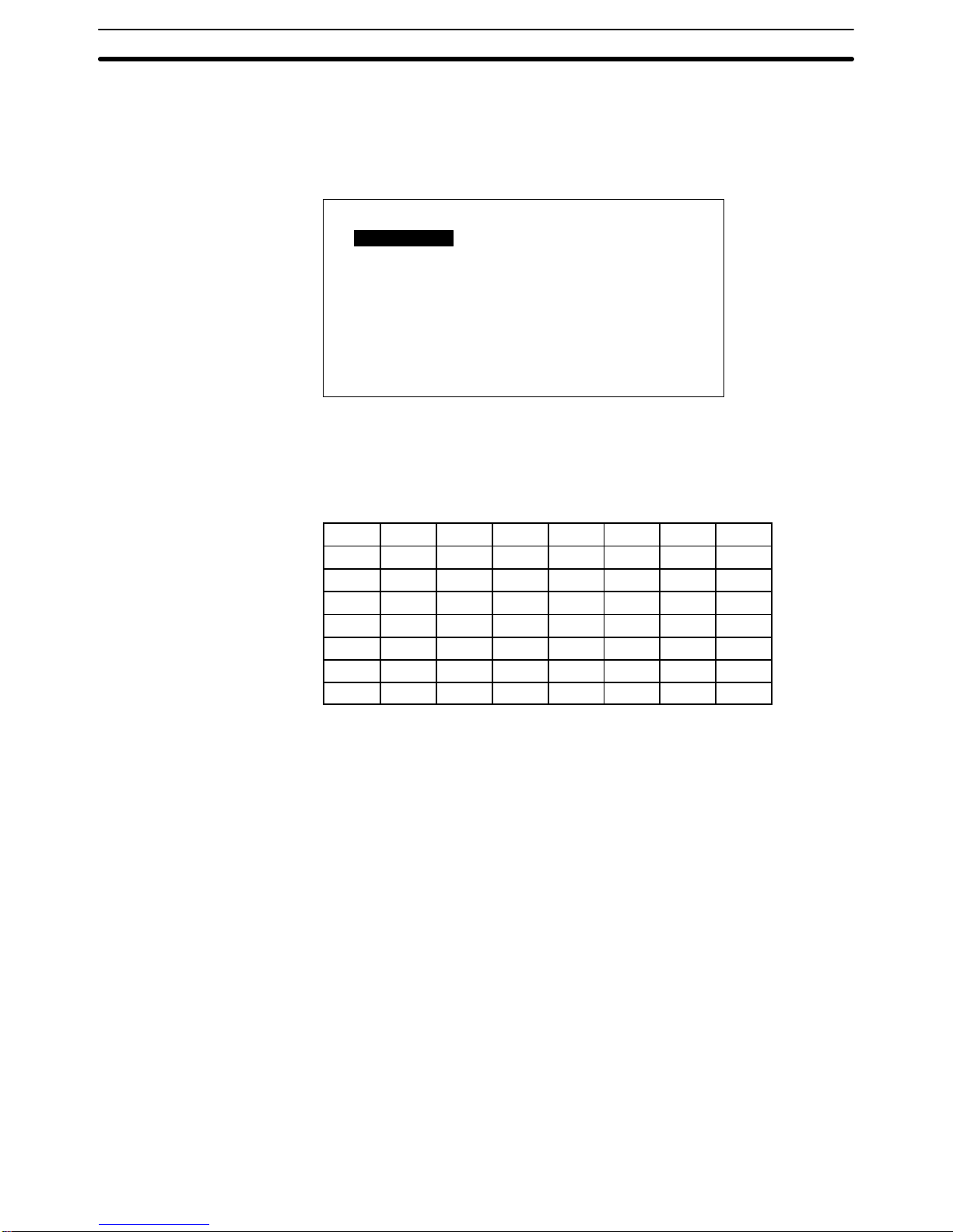
56
6-3-2 I/O Checks
In the Maintenance Mode Menu, use the Up and Down Keys to move the bar
cursor to I/O Check. When you then press the Enter Key, the following menu
will be displayed.
Quit
I/O CHECK MENU
Function Key
Touch Switch
Comm. Check
LCD Display
Buzzer
Backlight Check
Move the bar cursor to the item you want to check, and then press the Enter
Key.
Function Key Check
F1 F2 F3 F4 F5 F6 F7 F8
F9 F10 F11 F12 F13 F14 F15 F16
F17 F18 F19 F20 F21 F22 F23 F24
F25 F26 F27 F28 F29 F30 F31 F32
F33 F34 F35 F36 F37 F38 F39 F40
F41 F42 F43 F44 F45 F46 F47 F48
F49 F50 F51 F52 F53 F54 F55 F56
F57 F58 F59 F60 F61 F62 F63 F64
The operation of the function keys can be checked if a 12-key Function Key
Unit is connected. Press a function key. If the number of that key is displayed
in reverse video on the screen, then it is operating properly. Key numbers are
not transmitted to the host during the check operation. Up to two keys can be
pressed simultaneously.
The NT20M-FK210 has 12 standard function keys, so you can use F1 to
F12.
To return to the I/O Check Menu, press the Buzzer Key, Up Key, and Down
Key simultaneously.
A touch switch operation check can be carried out for PTs with touch panels (i.e.,
DT-type P Ts) by pressing each switch displayed on the screen. If a given switch
is displayed in reverse video after being pressed for approximately 0.5 second,
then that switch is okay. If “key input sound” is set to ON in the Memory Switch
Menu in Maintenance Mode, then the buzzer sounds simultaneously with the
reverse video display. The switch numbers are not transmitted to the host.
To return to the I/O Check Menu, press the Buzzer, Up, and Down system keys
simultaneously.
When external input terminals turn ON, the corresponding function keys are displayed in reverse video. When a 12-key Function Key Unit is connected, F1
through F12 correspond to IN0 through IN11.
Touch Switches (DT-type
PTs)
External Function Key Input
Check
Maintenance Mode Section 6-3
Page 62

57
To return to the I/O Check Menu, press the Buzzer, Up, and Down system keys
simultaneously.
F1
F9
F17
F25
F33
F41
F49
F57 F58
F50
F42
F34
F26
F18
F10
F2
F3
F11
F19
F27
F35
F43
F51
F59 F60
F52
F44
F36
F28
F20
F12
F4 F5
F13
F21
F29
F37
F45
F53
F61
F62
F54
F46
F38
F30
F22
F14
F6 F7
F15
F23
F31
F39
F47
F55
F63
F64
F56
F48
F40
F32
F24
F16
F8
When “lamp output check” is be displayed in reverse video, L1 will light. This indicates that output 1 is ON. Use the Up Key and the Down Key to move from
lamp to lamp to check their respective outputs. When the Up Key is pressed, the
next lamp to the right is displayed in reverse video. When the Down Key is
pressed, the next lamp to the left is displayed in reverse video.
When a 32/16 T erminal or a 10/02 Terminal is connected, the output corresponding to the lamp displayed in reverse video turns ON.
To return to the I/O Check Menu, press the Buzzer, Up, and Down system keys
simultaneously.
L1
L9
L17
L25
L33
L41
L49
L57 L58
L50
L42
L34
L26
L18
L10
L2
L3
L11
L19
L27
L35
L43
L51
L59 L60
L52
L44
L36
L28
L20
L12
L4 L5
L13
L21
L29
L37
L45
L53
L61
L62
L54
L46
L38
L30
L22
L14
L6 L7
L15
L23
L31
L39
L47
L55
L63
L64
L56
L48
L40
L32
L24
L16
L8
Note If a load (e.g., a buzzer or alarm light) is connected to a 10/02 Terminal or a 32/16
Terminal, it will actually operate. This can potentially be dangerous, so take the
necessary precautions.
Communications Check When “Communications Check” is selected, the Communications Check Menu
will be displayed.
Select one
COMMUNICATIONS CHECK MENU
Tool Interface
Host Interface
Tool Interface Check Data received from a connected Support Tool is displayed as is, in hexadecimal.
If any numbers are displayed, that means that the tool interface is okay. If nothing is displayed, then there may be a Support Tool, communications cable, or
communications hardware error.
Tool Interface Data transmitted from the Support Tool is displayed in hexadecimal.
Lamp Output Check
Maintenance Mode Section 6-3
Page 63

58
Tool I/F Input Check
1B 24 15 20
Host Interface (NT600M-LK201)
RS-232C I/F Input Check
1B 51 30 33
Data which is received will be displayed in hexadecimal.
Host Interface (NT600M-LK202)
RS-422 I/F Input Check
1B 24 15 20
Data which is received will be displayed just as it is, in hexadecimal.
LCD Display Check
The lines of the display are reversed one at a time, starting from the top of
the screen. When the reversal is finished, then they are cleared one at a
time. When all of them have been cleared, the I/O Check Menu is returned
to. You can interrupt the check and return to the I/O Check Menu by pressing
the Buzzer Key, Up Key, and Down Key simultaneously while the check is in
progress.
By selecting “Buzzer” from the I/O Check Menu, the PT buzzer can be
checked. The buzzer should produce a continuous sound. To stop the buzzer, press the Buzzer Key. While the buzzer is sounding, it will not be possible
to change screens or stop the buzzer by pressing the Buzzer Key, Up Key,
and Down Key simultaneously. The NT2000M has a buzzer enable/disable
pin. If this pin is removed, the buzzer cannot sound.
If “Backlight” is selected, the cycle from white (1 s) to red (1 s) to off will be
repeated. To stop the backlight check, press the Buzzer Key, Up Key, and
Down Key simultaneously. The NT20M-DT121-EV2 and the NT20MDN121-EV2 do not have red backlights.
6-3-3 PT Settings Check
The status of the PT and Host Interface Unit can be displayed, as well as the
settings of switches. Select “PT Settings” from the Maintenance Mode Menu.
Buzzer Check
Backlight Check
Maintenance Mode Section 6-3
Page 64

59
There are two screens, one for the PT and one for the Host Interface Unit,
and you can scroll up and down with the Up and Down Keys.
Internal Settings When PT Settings is selected, the internal settings of the PT are displayed
first.
PT Settings
Page
Memory Type RAM
Memory Size 128 KB
Mode Changes No
Exp. I/O Unit Standard (See Note 2)
↓
Note 1. Memory type and memory size are displayed only when the screen data
memory has been initialized. If it has not been initialized, then “N.A.” is
displayed.
2. If the PT is a DN type, and if an Expansion I/O Unit is connected, then the
types of Expansion I/O Unit will be displayed.
Standard: 12-key Function Key Unit
Not Connected
• If an 12-key Function Key Unit becomes disconnected during operation, a
continuous buzzer will sound and a “No Expansion I/O Unit” error message
will be displayed.
• To clear the error message, turn off the power supply and reconnect the
Expansion I/O Unit. Then turn the power supply back on.
Host Interface Unit Settings To display the DIP switch settings on the Host Interface Unit, press the Down
Key while the PT settings are being displayed.
RS-232C Host Link Units (NT600M-LK201)
RS-232C I/F Settings
Data Length 7 bits
Stop Bits 2 bits
Parity Even
Flow Control XON/XOFF
Baud Rate 9600 bps
Page
↑
RS-422 Host Interface Units (NT600M-LK202)
RS-422 I/F Settings
Terminal No. 01
Data Length 7 bits
Stop Bits 2 bits
Parity Even
Flow Control No
Baud Rate 9600 bps
Page
↑
For details on other Host Interface Unit models, refer to the Host Interface
Unit Operation Manual. To return to the Maintenance Mode Menu, press the
Buzzer Key, the Up Key, and the Down Key simultaneously.
Maintenance Mode Section 6-3
Page 65

60
6-3-4 Initialization
You must initialize the image data memory when using the SRAM or EEPROM for the first time. Initialization can also be used to clear all or part of
the data already registered in the PT.
Initializing Memory If you select Init. Memory in Maintenance Mode, a screen will be displayed
providing a selection of data to be initialized (i.e., image data, memory table
data, or history data). After one of the choices has been selected, another
screen will be displayed to confirm that you actually want to initialize that
data.
If you select Yes, then initialization will be executed and all of the selected
data will be deleted. (If memory table data is initialized, then the values set
by the Support Tool will be restored.
6-4 Memory Switch Settings
Memory switch settings set the NT20M display and key input sounds.
Select “Memory SW” from the Maintenance Mode Menu.
MAINTENANCE MODE MENU
Display History
I/O Check
PT Settings
Initialize Memory
Select one
MemorySwitch
Quit
Liquid Crystal Display Type Move the cursor to the item that is to be set and press the Enter Key. Each time
that it is pressed, the set value will change.
After the settings have been made, press the Buzzer, Up, and Down keys to return to RUN Mode. If the power to the NT20M is turned off at this point, the settings will not be registered.
Quit
MEMORY SW MENU
Key Input Sound ON
Backlight Off 10 min
Display Normal
Resume Function ON
Memory Switch Settings
Section 6-4
Page 66

61
EL Display Type
Quit
MEMORY SW MENU
Key Input Sound ON
Residual Image Elimination Function 1 hr
Resume Function ON
Contents of Settings
Item Setting Contents
Key input sound ON The buzzer sounds for 0.2 second when a system key, touch switch, or
function key is input.
OFF The buzzer does not sound when a system key, touch switch, or
function key is input.
Backlight off (LCD type) 10 min If no key input (see note 1) or
command (see note 2) is received
for 10 minutes while a screen is
being displayed, the backlight
turns off.
If a backlight-off command is
transmitted from the host, the
backlight turns off regardless of
this setting.
1 hr If no key input (see note 1) or
command (see note 2) is received
for one hour while a screen is
being displayed, the backlight
turns off.
None The backlight stays on constantly.
Display (LCD type) Normal The screen display is normal.
Reverse video The screen is displayed with dark and light reversed.
Residual image elimination
function (EL type)
10 min If no key input (see note 1) or command (see note 2) is received for 10
minutes while a screen is being displayed, the screen turns off.
1 hr If no key input (see note 1) or command (see note 2) is received for
one hour while a screen is being displayed, the screen turns off.
None The screen stays on constantly. The residual image
eliminationfunction does not operate, so turn off the screen periodically
by means of the host program.
Resume function ON The contents of memory tables written by the host during operation are
retained even if the NT20M power turns off or a reset is executed.
OFF If power to the NT20M is turned off or a reset is executed, the contents
of the memory table are overwritten by the contents of data created by
the Support Tool.
Note 1. Key Inputs
System keys, touch switches, function keys
2. Commands
Screen-change command
Setting screen overlap command (serial systems only)
On-line transfer completed command (Restart with change to RUN Mode)
Backlight-on command
3. The shaded areas represent the default settings.
When either “backlight off” or residual image elimination” is set to either “10 minutes” or “one hour,” the internal timer starts counting as soon as the key input or
command is received. When the time is up, the backlight or EL screen turns off.
The relevant key inputs and commands are as follows:
Operating Conditions for
the Backlight Off and
Residual Image
EliminationFunctions
Memory Switch Settings
Section 6-4
Page 67

62
When any one of the above key inputs or commands is received, the backlight
will be turned back on and the internal timer will start counting again. If a key input or command is then received before the time is up, the timer will be reset and
the count will start over.
Resume Function The resume function retains character string and numeral table data when pow-
er is interrupted or when the reset switch is pressed.
1, 2, 3... 1. When the Resume Function is Set to Off
The contents of character string and numeral tables are cleared when the
power to the PT is turned off or when the reset switch is pressed. After the
power is turned back on, or after the reset, character string and numeral
table data is read from the screen memory and operation begins again. If
new character string or numeral table data is transferred from the Support
Tool, that new data overwrites the data in the memory tables.
2. When the Resume Function is Set to On
If the power to the PT is turned off, or if the reset switch is pressed, the character string or numeral table data prior to the power interruption or reset is
retained. If new character string or numeral table data is transferred from the
Support Tool, the contents of the screen memory are refreshed but the
memory table data does not change. In order to return the contents of the
memory tables to the initial values that were created by the Support Tool,
execute “initialize memory table.”
Display Examples Depending on the setting of the resume function, the display at the time of pow-
ering up will be as follows:
Display at beginning
of operation.
The initial values
created by the Support
Tool are displayed.
Display just prior to power
interruption or reset.
Memory Table Data
Power turned OFF or reset switch pressed.
Display after power is turned
back to ON or after reset.
When resume function
is set to ON.
When resume function
is set to OFF.
0123
ABC
0123
ABC
9999
XYZ
9999
XYZ
Memory Switch Settings
Section 6-4
Page 68

63
SECTION 7
Online Transfer
This section describes transferring screens online to and from the host computer. Functions used to create screens and
control display attributes on the PT are described in Section 4 Display Functions. Functions used to input data on-screen
are described in Section 5 Input Functions. Data transfer and maintenance functions are described in Section 6 System
Menu.
Screen data can be transmitted online (i.e., in RUN Mode) by means of a Host Interface Unit command. For details on
commands, refer to information on online transfers in the Host Interface Unit Operation Manual. This function is valid
only for RS-232C and RS-422 Host Interface Units.
7-1 Transferring Screen Data 64. . . . . . . . . . . . . . . . . . . . . . . . . . . . . . . . . . . . . . . . . . . . . . . . . . .
7-2 Host to PT 64. . . . . . . . . . . . . . . . . . . . . . . . . . . . . . . . . . . . . . . . . . . . . . . . . . . . . . . . . . . . . . .
7-3 PT to Host 64. . . . . . . . . . . . . . . . . . . . . . . . . . . . . . . . . . . . . . . . . . . . . . . . . . . . . . . . . . . . . . .
7-4 Online Transmission and Resume Function 65. . . . . . . . . . . . . . . . . . . . . . . . . . . . . . . . . . . . .
Page 69

64
7-1 Transferring Screen Data
Screen data can be transferred along with screen numbers. Set the desired
screen number. If you set a screen number which is identical with one already registered in the PT, then the screen data for that number will be overwritten.
In addition to screen data, you can transfer memory tables and marks.
7-2 Host to PT
Screen data is transferred along with screen numbers. Any screen numbers
can be set. You can make a setting to transfer all screens or a screen of your
choice.
In addition to screen data, you can transfer memory tables, marks, and
history.
If data transmission is interrupted by a system key operation, the data received up to that point will be stored, but all data after that point will be corrupted.
If transmission of mark data is interrupted, the mark data will be received but
the accuracy of the data cannot be ensured. When the System Menu is
brought up, a message will be displayed indicating that the mark data has
been corrupted.
Transmit Mode
Screen during online transfer processing
Screen Data
System Memory
Memory Tables
Mark Data
History Info
PT ––> Host
Host ––> PT
Number of bytes transferred (in kilobytes).
KB
Shows direction
of data transfer.
Shows type of data.
7-3 PT to Host
Screen data can be transferred along with screen numbers. All screens or
desired screens can be transferred.
The memory table, mark, and display history can be transferred as well.
Screen data will not be corrupted when data transfer is interrupted with the
System Key.
PT to Host Section 7-2
Page 70

65
7-4 Online Transmission and Resume Function
Online transfer enables the Host to write data directly to the screen data
memory just like data transfer to the Support Tool. Therefore, the contents of
the display are influenced by the settings of the resume function.
9999
XYZ
2752
XYZ
9999
XYZ
2752
XYZ
Display after data reception
Reception
Display after reception of data
from the Host
Resume function turned ON
New data transfer on the Host
side
Resume function turned OFF
PT to Host Section 7-2
Page 71

67
SECTION 8
Maintenance and Inspection
This section provides troubleshooting and basic maintenance methods, including battery replacement.
8-1 Checking Operation 68. . . . . . . . . . . . . . . . . . . . . . . . . . . . . . . . . . . . . . . . . . . . . . . . . . . . . . .
8-2 Changing the Lithium Backup Battery 69. . . . . . . . . . . . . . . . . . . . . . . . . . . . . . . . . . . . . . . .
8-3 Replacing the Backlight 70. . . . . . . . . . . . . . . . . . . . . . . . . . . . . . . . . . . . . . . . . . . . . . . . . . . .
8-4 Maintenance and Inspection 71. . . . . . . . . . . . . . . . . . . . . . . . . . . . . . . . . . . . . . . . . . . . . . . . .
8-4-1 Spare Terminals 71. . . . . . . . . . . . . . . . . . . . . . . . . . . . . . . . . . . . . . . . . . . . . . . . . . .
8-4-2 Inspection 71. . . . . . . . . . . . . . . . . . . . . . . . . . . . . . . . . . . . . . . . . . . . . . . . . . . . . . . .
Page 72

68
8-1 Checking Operation
The hardware status of the PT can be checked with the Maintenance Menu.
Symptoms and corrective measures for errors that cannot be checked are
shown in the table below.
Symptom Probable cause Corrective measures, processing
POWER indicator
does not light.
Power is not being input, or power
supply is connected in inverse.
Provide a power supply with a rated voltage of 24 VDC.
Do not reverse polarity.
A fuse is blown. Contact your OMRON representative.
Message indicates no
Host Interface.
No Host Interface Unit is mounted. Mount a Host Interface Unit.
The System ROM is not compatible
with the Host Interface Unit.
Match the specifications of the System ROM and the
Host Interface Unit.
Screen does not
display.
System ROM is not installed, or
connections are faulty.
Check to be sure that the System ROM is installed, and
tighten the screws.
The memory installed does not
match the settings of SW2, or no
memory chip is installed.
Install a memory chip in socket and set SW2 correctly.
Contrast is not correct. Adjust the contrast with the contrast control.
Cannot communicate PT is not in Transmit Mode. Select Transmit Mode from the System Menu.
with Support Tool. There is a faulty connection with
the Support Tool.
Check connecting cables.
Cannot communicate
using Host Interface
Switch settings are not correct. Check PT settings under the Maintenance Mode and be
sure that settings match the host settings.
g
Unit (serial
communications)
Host Interface Unit connections are
faulty.
Check wiring of connecting cables.
Use shielded wire.
Check whether the cables are within the maximum
lengths.
For the NT600M-LK202, terminator
settings are not correct.
When using RS-422 communications, specify only the
last Terminal from the host as the terminator (turn on
termination resistance on the last Terminal only).
Cannot communicate
using Host Interface
Unit (parallel
communications)
The timing is off for
communications with the host
interface.
Check the timing of the DIP switch settings and the
host’s clock output.
Conduct a check using the “Communications Check” in
Maintenance Mode.
Lamp status is
retained when screens
are changed.
Lamps and touch switches are
overlapping.
Use touch switches as lamps just as they are. (Touch
switches have lamp functions.)
The buzzer sounds,
the RUN LED indicator
goes out, operation
suddenly stops, or the
display goes off and
does not return.
1) System ROM is not properly
installed.
2) Malfunction occurred due to
external noise.
1) Install the System ROM properly and lock it securely
in place.
2) Remove the communications cable from the source of
noise. Attach a noise filter to the power supply line.
Screen suddenly goes
blank.
Screen has changed to screen no.
0 at the host.
There is no error.
Corrupted Screen
Data
Screen data memory is bad.
The power was turned off or the
reset button was pressed during
transmission
1.) Replace the memory.
2.) Initialize the screen data memory and re-transfer the
data.
Checking Operation Section 8-1
Page 73

69
8-2 Changing the Lithium Backup Battery
A lithium battery is used in the NT20M and in the NT2000M. If the BAT LOW
indicator on the front panel lights, replace the battery within ten days.
Battery model 3G2A9-BAT08
Battery backup time 5 years at 25°C.
Replacement time Within 5 minutes from the time power is turned off.
Replacing the Battery
1, 2, 3... 1. Turn the power off. If the power has not been on, turn it on for at least
one minute and then turn it off again before replacing the battery.
2. Take off the battery cover on the back of the PT.
3. Remove the battery from the connector and put in a new battery. Be
sure that the connector is straight when inserted.
Note a) Do not take more than five minutes to replace the battery, other-
wise the internal memory may be lost.
b) The battery can be replaced with the PT turned on, in which case
there is no limitation for battery replacement time.
Caution Be sure not to touch the internal circuitry when replacing the battery with the
PT turned on, otherwise the internal circuitry may be short-circuited or an
electric shock accident may result.
Battery Set 3G2A9-BAT08
Battery connector
NT20M
Battery Set
Battery connector
NT2000M
3G2A9-BAT08
4. Replace the cover.
Caution The lithium battery can explode if placed into a fire, or it can explode, burn, or
leak if the + and – terminals are short-circuited or if the battery is recharged
or dismantled. Handle the battery with care.
Note If no battery is connected, BAT LOW indicator operation is not stable.
Changing the Lithium Backup Battery Section 8-2
Page 74
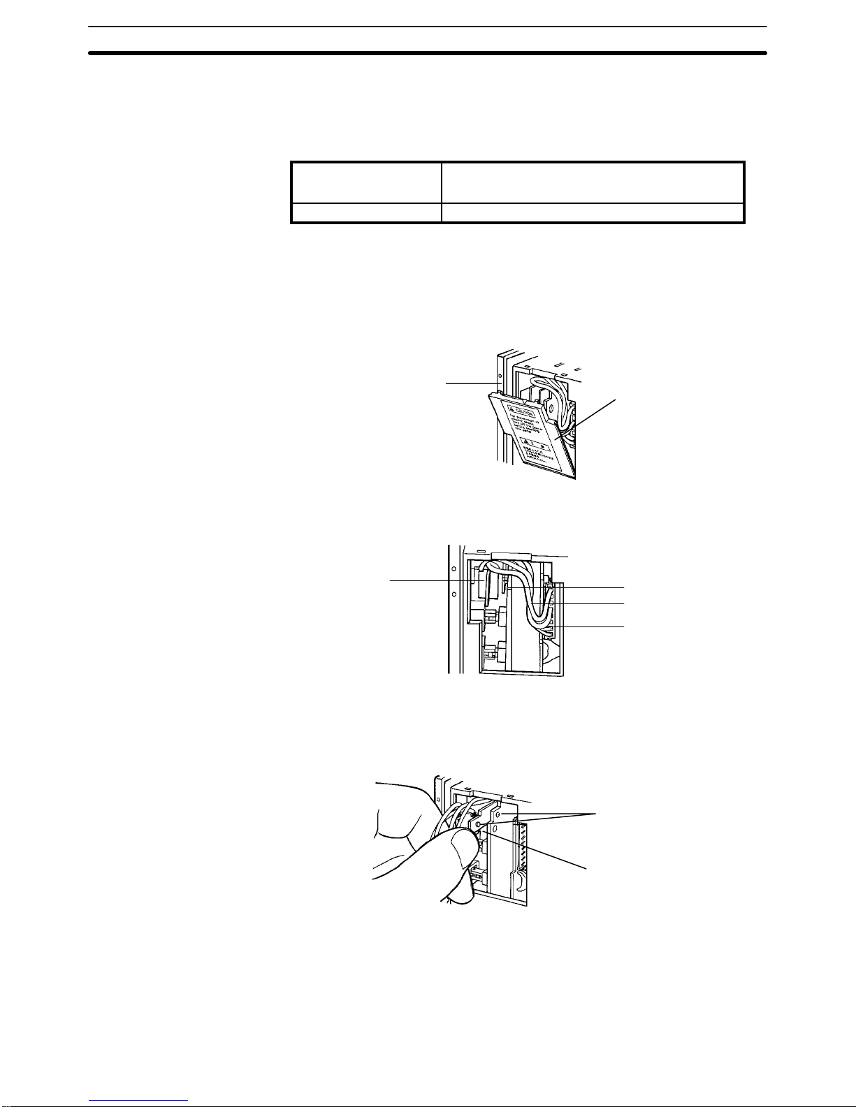
70
8-3 Replacing the Backlight
The backlight can be replaced for NT20M-DT13j, NT20M-DNj, and
NT2000M-Dj131 PTs. When the screen begins to flicker or get darker, replace the backlight by replacing the CFL Unit.
CFL Unit model For NT20M: NT20M-CFL01
For NT2000M: NT200M-CFL01
Service life (See note) Approx. 20,000 hours at 25°C.
Note The service life is taken to be the time it takes for the backlight to lose 50% of
its brightness.
1) Turn off the power to the PT.
2) Pull out the backlight cover on the right side of the PT by placing your fin-
ger on the top and pulling it forward.
NT20M
Cover
3) Pull out the attached CFL Unit cord and slowly pull off the connector, being
careful to pull it straight.
CFL Unit
Lock mechanism
Cord
Connector
4) On the right side of the CFL Unit there is a latch. Bend it to the left (i.e., to
the side of the PT display panel) to unlock the CFL Unit from the print board.
Then pull the CFL Unit straight out. Be careful not to directly touch the fluorescent tube.
Lock mechanism
Latch
5) Insert the new CFL Unit, and bend the latch back to lock the CFL Unit to
the print board. If it is difficult to insert it, the cord may be getting in the way.
Do not try to force it, but just push the cord to the top and insert the CFL Unit
slowly.
6) Insert the connector, being careful to match the polarity. Fit the cord in and
replace the cover.
NT20M-DT/DN13j
Backlights
Maintenance and Inspection Section 8-4
Page 75

71
1) Turn off the power to the PT.
2) Remove the backlight case at the rear of the PT, by pressing on the place
where it is indicated and pushing upward.
Hooks
3) Pull off the attached CFL Unit connector and remove the CFL Unit.
Connector
Latches
CFL Unit
4) Install the new CFL Unit and insert the connector, being careful to match
the polarity.
5) Replace the backlight case, and snap it carefully in place.
Latch
Hook
Notch
Caution To avoid electrical shock, be sure to turn off the power before removing the
backlight cover.
Be sure to put the cover back on after replacing the CFL Unit.
8-4 Maintenance and Inspection
8-4-1 Spare Terminals
In order to restore operations as quickly as possible in the event of a PT
breakdown, it is a good idea to always keep a spare PT on hand.
8-4-2 Inspection
If the PT screen gets dirty, it will become hard to read. Be careful of the following points when cleaning it.
• When cleaning, wipe with a dry, soft cloth. If the dirt does not come off, then
moisten the rag with water and rub hard.
NT2000M-Dj131
Backlights
Maintenance and Inspection Section 8-4
Page 76

72
• Wiping with a chemical cloth or with volatile solutions such as benzine or
thinner may cause degeneration. A little alcohol may be used if necessary.
• Prolonged contact with rubber, vinyl products, or tape may leave marks.
• The PT’s liquid crystal display and backlight can wear out. If they become
hard to see, replace the PT. The backlight of the NT20M-DT121-V2 or
DN121-V2 cannot be replaced.
• The standard inspection period is once every 6 to 12 months, but it should
be moved up if the operating environment is harsh. If there is any deviation
from the criterion, then it should be corrected.
Inspection item Inspection content Criterion Method/tools
Power supply Measure at the power supply terminal block. Are
voltage fluctuations within the criterion?
Voltage fluctuation range:
NT20M: 20.4 to 26.4 VDC
NT2000M: 85 to 264 VAC
Tester
Operating
environment
Is the ambient temperature (the temperature inside of
the panel) suitable?
NT20M: 0°C to 45°C
NT2000M: 0°C to 50°C
Thermometer
Is the ambient humidity (the humidity inside of the
panel) suitable?
35% to 85% There should
be no condensation.
Hydroscope
Is dust collecting? There should be no dust. Visual
Installation Is each Terminal firmly secured? There should be no loose
screws.
Phillips
screwdriver
Are the connectors for the connecting cable inserted
perfectly and locked?
There should be no loose
screws.
---
Are any screws for the external wiring coming loose? There should be no loose
screws.
Phillips
screwdriver
Is any external wiring loose or disconnected? There should be no external
abnormalities.
Visual
Replaceable
parts
Can you read the characters on the liquid crystal
display?
Is the backlight illumination as bright as it should be?
Average life expectancy of
liquid crystal: 50,000 hrs
Average life expectancy of
backlight: 20,000 hrs
Visual
Precautions for Handling
• Turn off the power before replacing a PT.
• When you discover what seems to be a defective PT, check it again before
replacing it to be sure that the problem is actually with the PT.
• When returning a defective PT for service, please describe the problem in
as much detail as possible. Send the PT to the OMRON office closest to
you.
Tools for Inspection
• Phillips and flat-blade screwdrivers
• Voltage tester or digital voltmeter
• Industrial alcohol and all-cotton cloth
Measuring Instruments (Depending on Case)
• Synchroscope
• Oscilloscope with pen output
• Thermometer
• Hydroscope
Maintenance and Inspection Section 8-4
Page 77
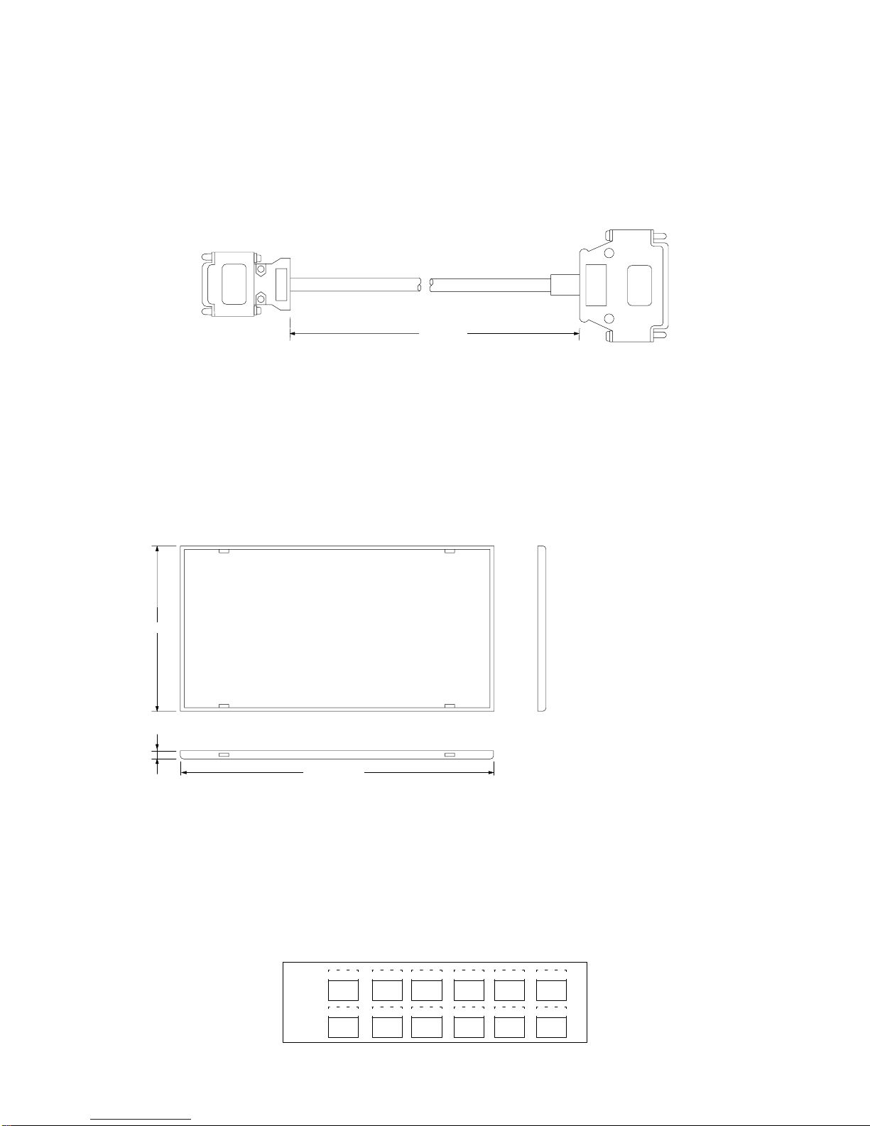
73
Appendix A
Standard Models
RS-232C Connecting Cable for Connecting Devices (CV500-CN228)
2 ,000
+150
–0
Note The personal computer end of the CV500-CN228 Connecting Cable is a 25-pin D-sub male con-
nector. To connect to an IBM PC/AT or compatibles, a 9-pin or 25-pin D-sub female adapter is
required.
Dustproof Cover
NT20M-KBA01 (for NT20M-DT/DN)
NT20M-KBA02 (for NT20M-DN connected to NT20M-FK210)
Under severe conditions, this cover can be used to protect the display area and controls from oil and dust.
112.4 ±0.3
222.4 ±0.3
5.7
NT20M-KBA01 dimensions (mm)
Material: Silicon rubber
NT20M-CFK01 Key Sheets (Five Sheets)
Use these sheets for NT20M-FK210 function keys. By simply peeling them off of the paper, you can easily
write on them and attach them. You can also rub off anything written with oil-base ink. If they get dirty, you can
easily remove and replace them.
Square
hole
Page 78
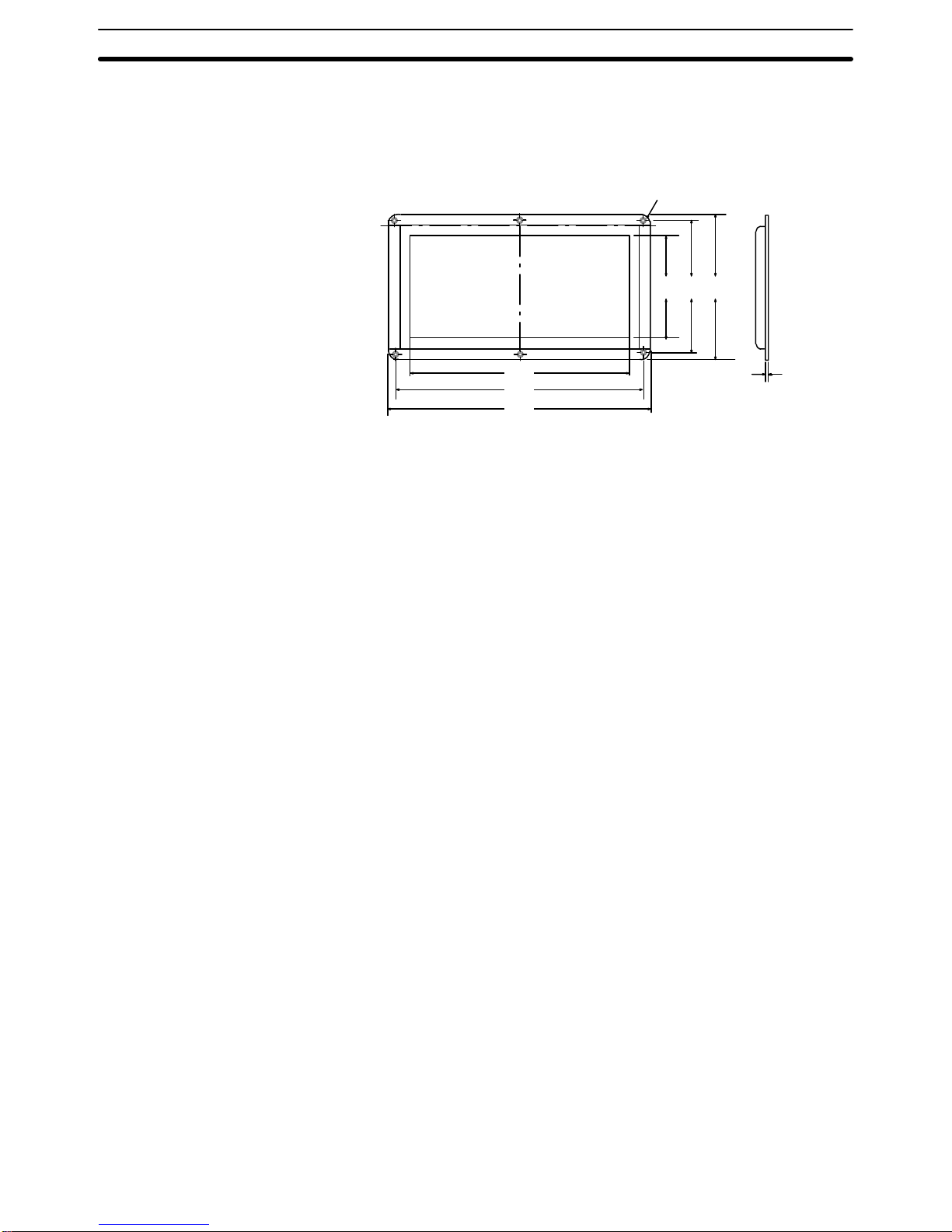
Appendix AStandard Models
74
NT20M-KBA03 Oil Resistance Kit
Mount this kit to the display panel of the NT20M to protect from dirt and oil. (This kit cannot be mounted at the
same time as an NT20M-FK210 Function Key Unit. In addition, when it is mounted it is not possible to access
under the Support Tool connector cover.
Six M3 flat-head screws
206
230
243
96 124 133
7.9
Page 79
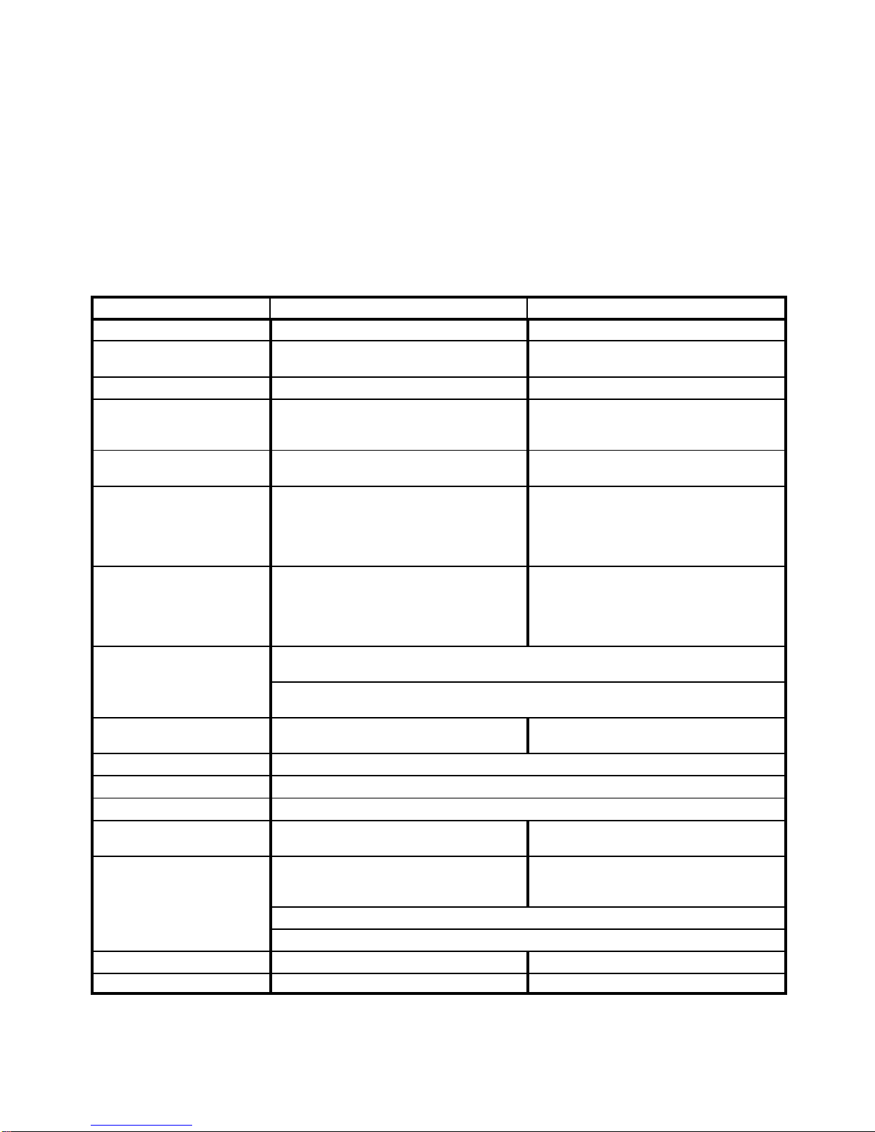
75
Appendix B
Specifications
General Specifications
Item NT20M NT2000M
Power supply voltage 24 VDC 100 to 240 VAC
Allowable power supply
voltage range
20.4 to 26.4 VDC, (24 VDC
–15%
/
+10%
) 85 to 264 VAC (50/60 Hz)
Power consumption 12 W max. 40 VA max.
Insulation resistance ___ 20 MΩ min. (at 500 VDC megger) between
the AC external terminals and the GR
terminal
Voltage resistance ___ 2300 VAC max. for 1 min. at 50/60 Hz
(Leakage current: 0.8 mA max.)
Noise resistance (24 VDC) Common (between power
supply and panel): 1,000 V
P-P
Normal: 300 V
P-P
Pulse width: 100 ns to 1 ms
Pulse rise time: 1 ns
AC 1,000 V
P-P
Pulse width: 100 ns to 1 ms
Pulse rise time: 1 ns
Vibration resistance 10 Hz to 22 Hz: 1.5-mm double amplitude
X, Y, and Z directions
22 Hz to 500 Hz:
Acceleration: 1.5 G (14.7 m/s
2
)
X, Y, and Z directions for 30 min total
10 Hz to 50 Hz: 0.5-mm single amplitude;
Acceleration: 2.0 G (19.6 m/s
2
)
X, Y, and Z directions for 1 hour each
Shock resistance
30 G (294 m/s2)
3 times each in X, Y, and Z directions
20 G (196 m/s2)
3 times each in X, Y, and Z directions
Ambient operating
temperature
0°C to 45°C (with no freezing) 0°C to 50°C (with no freezing)
Ambient operating humidity 35% to 85% (with no condensation.)
Operating environment No corrosive gas
Storage temperature –20°C to 70°C (with no freezing)
Allowable power interruption
time
1)
5 ms max. (one minute or more after
power is turned on)
20 ms max.
Enclosure ratings
Front control panel IP52F (Drip-proof
when dust cover is installed, as long as
NT20M-FK210 is not mounted.)
IP65F or equivalent. Do not expose to
direct jet stream for longer than one
minute.
Rear case: IP20
Terminal section IP00
Weight 1.2 kg max. Approx. 3 kg
Dimensions 220 (W) x 110 (H) x 82 (D) 365 (W) x 232.5 (H) x 77 (D)
Note 1. Even if a power interruption is outside of the allowable range, PT operation can still be continued
but there is a possibility of data being corrupted if it occurs during communications with the Support Tool or the host when PT settings are made with system keys.
Page 80

Appendix BSpecifications
76
Characteristics
Display Specifications
Item Specifications
Display screen Dot matrix STN liquid crystal display panel
No. of dots: 256 x 128
NT20M: j0.407 mm
NT2000M: j1.04 mm
Effective display area: NT20M: 112 mm x 56 mm
NT2000M: 275 x 138 mm
Service life expectancy: 50,000 hrs min.
View angle (right/left direction)
NT20M-Dj12j: ±30°
NT20M-Dj13j ±40° (when white backlight is lit)
NT2000M-Dj131 ±45° (when red backlight is lit)
Backlight
White cold-cathode tube (NT20M-Dj13j and NT2000M-Dj131 can change
between red and white backlights.)
Service life expectancy: 10,000 hrs min. (20,000 hrs average)
Automatic turn-off: Can be set to not turn off, or to turn off in 10 min or 1 hr
Indicators Three indicators:
POWER indicator (Green LED): Lit when power is being supplied.
RUN indicator (Green LED): Lit during operation.
BAT LOW indicator (Red LED): Lit when battery voltage level drops.
Control Panel Specifications
Item Specifications
System keys Four keys: buzzer-stop, up-scroll, down-scroll, execute (enter)
Functions: System Menu selection, buzzer off, bar cursor movement, up/down scroll for
continuous screens, execution of numeric settings
Touch panel (DT type) Maximum: 64 touch switches per screen
Pressure-sensitive
Operating force: 100 g max.
Life expectancy: 1,000,000 operations min.
12-key Function Key Unit
NT20M-FK210 (Connectible
to NT20M-DN type)
No. of keys: 12 (fixed)
Switch type Pressure-sensitive
Key sheets are replaceable.
Note The 2-point output is the contact relay type. For the socket type, it can be replaced by a no-con-
tact relay such as a transistor or triad.
Display Capacity
Item Specifications
Display characters Half-size characters (8 x 8 dots): Alphanumerics and symbols
Normal characters (8 x 16 dots): Alphanumerics and symbols
Marks (16 x 16 dots): User defined, 64 max.
Number of characters
displayed
Standard-size characters: Max. 32 characters horizontal x 8 vertical
Wide characters: Max. 16 characters horizontal x 8 vertical
Enlargement function Horizontal, vertical, 4 times, 9 times, 16 times
Display attributes Inverse, blinking, inverse blinking
Character displays Displays any characters (screen number designation).
Graphics Polylines (broken continuous line) and circles
Terminal mode Characters, numeric values, and graphic designated by the host are displayed
(RS-232C or RS-422 interface required).
String displays Maximum 32 total, 8 per screen and 32 bytes per string
Numeral displays Maximum 128 total, 50 per screen
Page 81

Appendix BSpecifications
77
Item Specifications
Bar graph display 2 to 255 dots; +/– area display;% display capability
Overlapping screens Overlapping of a maximum of 8 registered screens is possible.
Continuous screens Scrolling the display for a maximum of 8 registered screens is possible.
No. of registered screens 250 max.
Screen registration method Transfer to the PT data created at IBM PC/AT compatible, or mount EPROM chip
containing data.
Screen saving method Can be saved to SRAM (with backup battery), EEPROM or EPROM.
Screen attribute settings Alarm, continuous buzzer, intermittent buzzer, function key bit input, touch switch bit
input, display history, 10-key, backlight
Data Quantities
Item Specifications
Mark data 64 max.
String data 32 characters (standard size characters) x 32 strings max.
Numeral data 8 digits x 128 values max.
Switches Switches and lamps combined: 256 max.
Lamps
(There is no limit when Host Link direct connection is used.)
Special Features
Item Specifications
Alarm output Relay output on rear terminal block.
Rating: NT20M: 1 A at 24 VDC
NT2000M: 1 A at 24 VDC
Output condition: NO contact (Closes when a command is received from the host or
when there is a screen called with an alarm-ON specification.)
Host RUN input Photocoupler input on rear terminal block.
Rating 24 VDC
+10%
/
–15%
When this input goes OFF, the PT will display “host error” regardless of other conditions.
Buzzers Two types: Continuous sound and intermittent sound.
ON: The buzzer will sound when a command is received from the host, or when
a screen with a buzzer-ON specification is called.
OFF: The buzzer is turned OFF when the Buzzer Key is pressed, when a
command is received from the host, or when a screen without a buzzer-ON
specification is displayed.
Sound pressure: 80 dB min./87 dB average (Measured at 10 cm from front panel.)
Enabled/disabled (NT2000M only): The buzzer sound can be enabled or disabled
by means of a setting pin. If it is disabled, the buzzer will not sound under
any conditions.
Maintenance functions Self-test for memory, switches, etc.
Status setting confirmation for communications and other conditions.
Simple communications confirmation.
Battery backup Data backed up by lithium battery when screen data memory is SRAM.
Data backup time: 5 years (at 25°C)
If there is a voltage drop, the BAT LOW indicator on the front panel will light and the
Battery Low Flag to the host will turn ON.
The battery can be replaced from the rear of the Terminal while power is on.
Key input sound setting If Key Input Sound is set to ON in the Memory Switch Menu, a beep will sound for 0.2 s
when a system key, function key, or touch switch is pressed.
Page 82

79
Index
A
abbreviations, 3
alarms, controlling from host, 43
ALM OUTPUT terminals, 25
ASCII Unit, 6, 7
B
backlight, controlling from host, 42
bar graphs, displaying, 41
battery, replacing, 69
buzzer, controlling from host, 43
C
cable, 73
child screens, 37, 38
communications, setting for NT20-LK201/LK203-E, 14
communications errors, automatic reset setting, 14
contract control, 9
control panel, specifications, 76
cover, 73
D
data transfer, PT to host, 46
dimensions, 17
DIP switch, 9
display
attributes, 36
capacity, 76
character scale, 36
characters, 36
data quanitities, 77
LCD check, 58
positioning, 36
specifications, 76
display history, 53
controlling from host, 43
initializing, 60
E
error messages, 32
F
function key input screen, 47
function keys, checking, 56
H
host computer
controlling PT operation, 42
data transfer, 39, 40, 41, 44, 46, 47
Host Interface Units, displaying settings, 58
Host Link Unit, interface, 7, 8
HOST RUN INPUT
controlling from host, 43
enable/disable setting, 14
HOST RUN INPUT terminals, 24
I
I/O checks, 56
initialization, 60
memory, 30
installation
environment, 16
mounting position, 16
panel mounting, 18
K
Key Sheets, 73
L
lamps
attributes, 41
displaying, 41
language, setting, 14
LG and GR terminals, 23
M
Maintenance Mode, 53
maintenence, inspection, 71
memory, initializing, 30
memory capacity, 5
memory chips, 5
memory switch settings, 15
Page 83

Index
80
menus
overview, 31
selecting items, 31
system menu, 52
mode changes, enable/disable setting, 14
models, 4
N
nomenclature, 8
numeral table, 39, 41, 47
numeric display, 39
numeric settings, 47
P
parent screens, 37, 38
power supply
24-VDC input terminals, 22
AC input terminals, 23
wiring, 22
PT settings, displaying, 58
R
RS-232C connector, 9
RS-232C interface, 6
connector, 26
RS-422 interface, 7
S
screen memory, initializing, 60
screens
changing, 36
continuous screens, 37
examples, 36
maximum limit, 5
overlapping screens, 38
transferring online, 64
setting, defaults, 33
specifications, 75
special features, 77
string table, 40
Support Tool, 6
checking interface, 57
Support Tools, data transfer, 32
switch inputs, transferring to host, 46
SYSMAC BUS, interface, 7
system configuration, 6
system keys, 31
System Menu, 53
System ROM, selecting, 5
T
terminology, 3
text strings, displaying, 40
touch switches, 46
Transmit Mode, 53
troubleshooting, 68
W
wiring
ALM OUTPUT terminals, 25
HOST RUN INPUT terminals, 24
LR and GR terminals, 23
power supply, 22
RS-232C connector, 26
terminal block, 21
Page 84

81
Revision History
A manual revision code appears as a suffix to the catalog number on the front cover of the manual.
Cat. No. V001–E1–2
Revision code
The following table outlines the changes made to the manual during each revision. Page numbers refer to the
previous version.
Revision code Date Revised content
1 November 1991 Original production
1A October 1992 Page 3: A row defining the C200H has been added to the SYSMAC terminology table.
Manual numbers have been changed in the Reference Manuals table.
Page 4: The numbers of registered screens have been changed in the Memory Capacity
and Number of Screens table. The model legend for the system ROM has been changed
to incorporate the C200H. A model number for the Host Interface Units has been added to
the table.
Page 5: C200H Interface has been added to the list of allowable interfaces for communications in 1-4-2 Operation.
Page 7: A C200H Interface description has been added.
Page 10: “Transfer Mode” has been changed to “Transmit Mode” for pin 6 of the switch set-
tings table.
Page 11: SW1 has been changed to SW3 in the table.
Page 23: “Transfer Mode” has been changed to “Transmit Mode” within the procedure.
Page 26: The description within 4-1-3 Character Scale has been changed.
Page 32: NT20M-LB121-EV1 Host Interface Unit has been added to the Note at the bottom
of the page.
Page 49: A description for the C200H Host Interface Units (NT20M-LB121-EV1) has been
added.
Page 51: A description for the C200H Host Interface Units (NT20M-RT121-EV1) has been
added.
Page 59: A row for the C200H Host Interface Units has been added to the table.
2 September 1993 Page 2: A general introduction was added, describing the basic functions of PTs.
Pages 2 and 3: Some new features were added.
Page 4: Descriptions of NT20M and NT2000M PTs were added.
Page 5: Information was added about selecting System ROM.
Page 6: Information was added about the Support Tool.
Pages 7 and 8: Changes were made to system configuration illustrations.
Pages 9 to 12: Illustrations were added showing features and components of PT.
Page 14: Revisions were made to DIP switch settings.
Page 15: Revisions were made to memory settings.
Pages 15 to 20: NT2000M installation information was added.
Pages 21 to 27: NT2000M wiring and connector information was added.
Pages 30 t o 3 1 : Information was added concerning powering up and initializing the memory.
Pages 36 to 44: Information was added regarding NT2000M display functions.
Pages 48 to 50: Information was added regarding numeric input.
Page 52: Changes were made to menu illustration.
Pages 53 to 59: Changes were made to information regarding Maintenance Mode.
Pages 64 to 69: Changes were made and information was added regarding maintenance
and inspection procedures.
Appendix A: Changes made to optional items.
Appendix B: Changes made to specifications.
Page 85

OMRON Corporation
Control Devices Division H.Q.
Shiokoji Horikawa, Shimogyo-ku,
Kyoto, 600-8530 Japan
Tel: (81)75-344-7109/Fax: (81)75-344-7149
Regional Headquarters
OMRON EUROPE B.V.
Wegalaan 67-69, NL-2132 JD Hoofddorp
The Netherlands
Tel: (31)2356-81-300/Fax: (31)2356-81-388
OMRON ELECTRONICS LLC
1 East Commerce Drive, Schaumburg, IL 60173
U.S.A.
Tel: (1)847-843-7900/Fax: (1)847-843-8568
OMRON ASIA PACIFIC PTE. LTD.
83 Clemenceau Avenue,
#11-01, UE Square,
Singapore 239920
Tel: (65)6835-3011/Fax: (65)6835-2711
OMRON (CHINA) CO., LTD.
Room 2211, Bank of China Tower,
200 Yin Cheng Zhong Road,
PuDong New Area, Shanghai, 200120 China
Tel: (86)21-5037-2222/Fax: (86)21-5037-2200
Page 86

Cat. No. V001-E1-2 Note: Specifications subject to change without notice.
Printed in Japan
0993-1.4M (1191)
Authorized Distributor:
 Loading...