

Page 1

Cat. No. V091-E1-01
NT20
Programmable Terminal
USER’S MANUAL
Page 2
NT-series Programmable Terminal
User’s Manual
Produced March 2007
Page 3

iv
Page 4

Notice:
r
f
OMRON products are manufactured for use according to proper procedures by a qualified operator
and only for the purposes described in this manual.
The following conventions are used to indicate and classify precautions in this manual. Always heed
the information provided with them. Failure to heed precautions can result in injury to people or damage to property.
!DANGER Indicates an imminently hazardous situation which, if not avoided, will result in death or
serious injury. Additionally, there may be severe property damage.
!WARNING Indicates a potentially hazardous situation which, if not avoided, could result in death or
serious injury. Additionally, there may be severe property damage.
!Caution Indicates a potentially hazardous situation which, if not avoided, may result in minor or
moderate injury, or property damage.
OMRON Product References
All OMRON products are capitalized in this manual. The word “Unit” is also capitalized when it refers to
an OMRON product, regardless of whether or not it appears in the proper name of the product.
The abbreviation “Ch,” which appears in some displays and on some OMRON products, often means
“word” and is abbreviated “Wd” in documentation in this sense.
The abbreviation “PLC” means Programmable Controller. “PC” is used, however, in some Programming Device displays to mean Programmable Controller.
The abbreviation “Host” means a PLC that controls the NT20.
Visual Aids
The following headings appear in the left column of the manual to help you locate different types of
information.
OMRON, 2007
All rights reserved. No part of this publication may be reproduced, stored in a retrieval system, or transmitted, in any form, o
by any means, mechanical, electronic, photocopying, recording, or otherwise, without the prior written permission o
OMRON.
No patent liability is assumed with respect to the use of the information contained herein. Moreover, because OMRON is constantly striving to improve its high-quality products, the information contained in this manual is subject to change without
notice. Every precaution has been taken in the preparation of this manual. Nevertheless, OMRON assumes no responsibility
for errors or omissions. Neither is any liability assumed for damages resulting from the use of the information contained in
this publication.
Note Indicates information of particular interest for efficient and convenient opera-
tion of the product.
1,2,3... 1. Indicates lists of one sort or another, such as procedures, checklists, etc.
v
Page 5

vi
Page 6

TABLE OF CONTENTS
PRECAUTIONS . . . . . . . . . . . . . . . . . . . . . . . . . . . . . . . . . . . xvii
1 Intended Audience. . . . . . . . . . . . . . . . . . . . . . . . . . . . . . . . . . . . . . . . . . . . . . . . . . . . . . . . . xviii
2 General Precautions. . . . . . . . . . . . . . . . . . . . . . . . . . . . . . . . . . . . . . . . . . . . . . . . . . . . . . . . xviii
3 Safety Precautions . . . . . . . . . . . . . . . . . . . . . . . . . . . . . . . . . . . . . . . . . . . . . . . . . . . . . . . . . xviii
4 Operating Environment Precautions . . . . . . . . . . . . . . . . . . . . . . . . . . . . . . . . . . . . . . . . . . . xix
5 Application Precautions. . . . . . . . . . . . . . . . . . . . . . . . . . . . . . . . . . . . . . . . . . . . . . . . . . . . .xix
6 EC Directives. . . . . . . . . . . . . . . . . . . . . . . . . . . . . . . . . . . . . . . . . . . . . . . . . . . . . . . . . . . . . xx
SECTION 1
Functions of the NT20 . . . . . . . . . . . . . . . . . . . . . . . . . . . . . . 1
1-1 Role and Operation of NT20 . . . . . . . . . . . . . . . . . . . . . . . . . . . . . . . . . . . . . . . . . . . . . . . . . 2
1-2 Functions of NT20. . . . . . . . . . . . . . . . . . . . . . . . . . . . . . . . . . . . . . . . . . . . . . . . . . . . . . . . . 4
1-3 Method for Connection to the Host . . . . . . . . . . . . . . . . . . . . . . . . . . . . . . . . . . . . . . . . . . . . 8
1-4 Communications with PLC by Direct Connection . . . . . . . . . . . . . . . . . . . . . . . . . . . . . . . . 10
1-5 Communications Using RS-232C (NT20-ST128) . . . . . . . . . . . . . . . . . . . . . . . . . . . . . . . . 13
1-6 Before Operating . . . . . . . . . . . . . . . . . . . . . . . . . . . . . . . . . . . . . . . . . . . . . . . . . . . . . . . . . . 14
SECTION 2
Hardware Settings and Connections. . . . . . . . . . . . . . . . . . . 17
2-1 Description of Parts and Settings. . . . . . . . . . . . . . . . . . . . . . . . . . . . . . . . . . . . . . . . . . . . . . 18
2-2 Installation . . . . . . . . . . . . . . . . . . . . . . . . . . . . . . . . . . . . . . . . . . . . . . . . . . . . . . . . . . . . . . . 21
2-3 Connecting Link Adapters and RS-422A Converters . . . . . . . . . . . . . . . . . . . . . . . . . . . . . . 24
2-4 Connecting the NT Support Tool. . . . . . . . . . . . . . . . . . . . . . . . . . . . . . . . . . . . . . . . . . . . . . 35
2-5 Using a Memory Unit . . . . . . . . . . . . . . . . . . . . . . . . . . . . . . . . . . . . . . . . . . . . . . . . . . . . . . 36
2-6 Connecting to the RS-232C Port at the Host. . . . . . . . . . . . . . . . . . . . . . . . . . . . . . . . . . . . . 44
2-7 Communicating with the PLC Using C200H Direct Communications. . . . . . . . . . . . . . . . . 73
2-8 Host Connections by RS-232C (NT20-ST128). . . . . . . . . . . . . . . . . . . . . . . . . . . . . . . . . . . 79
SECTION 3
System Menu Operation. . . . . . . . . . . . . . . . . . . . . . . . . . . . . 81
3-1 Operation Flow by the System Menu . . . . . . . . . . . . . . . . . . . . . . . . . . . . . . . . . . . . . . . . . . 82
3-2 Starting the NT20 . . . . . . . . . . . . . . . . . . . . . . . . . . . . . . . . . . . . . . . . . . . . . . . . . . . . . . . . . 83
3-3 Operation Modes and the System Menu . . . . . . . . . . . . . . . . . . . . . . . . . . . . . . . . . . . . . . . . 84
3-4 Initializing Memory . . . . . . . . . . . . . . . . . . . . . . . . . . . . . . . . . . . . . . . . . . . . . . . . . . . . . . . . 88
3-5 Setting the Conditions of Communications with the Host by Using the Memory Switches. 91
3-6 Registering the Screen Data. . . . . . . . . . . . . . . . . . . . . . . . . . . . . . . . . . . . . . . . . . . . . . . . . .102
3-7 Starting the Operation . . . . . . . . . . . . . . . . . . . . . . . . . . . . . . . . . . . . . . . . . . . . . . . . . . . . . . 105
3-8 Various System Settings . . . . . . . . . . . . . . . . . . . . . . . . . . . . . . . . . . . . . . . . . . . . . . . . . . . . 106
3-9 System Maintenance . . . . . . . . . . . . . . . . . . . . . . . . . . . . . . . . . . . . . . . . . . . . . . . . . . . . . . . 115
3-10 Transferring the System Program . . . . . . . . . . . . . . . . . . . . . . . . . . . . . . . . . . . . . . . . . . . . . 126
3-11 Transferring the Resource Data. . . . . . . . . . . . . . . . . . . . . . . . . . . . . . . . . . . . . . . . . . . . . . . 129
vii
Page 7

TABLE OF CONTENTS
SECTION 4
NT20 Functions and Operation . . . . . . . . . . . . . . . . . . . . . . . 133
4-1 Screen Creation Procedure . . . . . . . . . . . . . . . . . . . . . . . . . . . . . . . . . . . . . . . . . . . . . . . . . .134
4-2 Outline of Functions . . . . . . . . . . . . . . . . . . . . . . . . . . . . . . . . . . . . . . . . . . . . . . . . . . . . . . . 136
4-3 Screen Display . . . . . . . . . . . . . . . . . . . . . . . . . . . . . . . . . . . . . . . . . . . . . . . . . . . . . . . . . . . . 140
4-4 Memory Tables . . . . . . . . . . . . . . . . . . . . . . . . . . . . . . . . . . . . . . . . . . . . . . . . . . . . . . . . . . . 144
4-5 Bar Graphs . . . . . . . . . . . . . . . . . . . . . . . . . . . . . . . . . . . . . . . . . . . . . . . . . . . . . . . . . . . . . . . 147
4-6 Lamps . . . . . . . . . . . . . . . . . . . . . . . . . . . . . . . . . . . . . . . . . . . . . . . . . . . . . . . . . . . . . . . . . . 150
4-7 Touch Switches . . . . . . . . . . . . . . . . . . . . . . . . . . . . . . . . . . . . . . . . . . . . . . . . . . . . . . . . . . . 152
4-8 Numeral Setting . . . . . . . . . . . . . . . . . . . . . . . . . . . . . . . . . . . . . . . . . . . . . . . . . . . . . . . . . . . 156
SECTION 5
How to Use the Host Link/NT Link . . . . . . . . . . . . . . . . . . . 165
5-1 Overview of Direct Connection Operations . . . . . . . . . . . . . . . . . . . . . . . . . . . . . . . . . . . . . 166
5-2 Memory Tables and Bar Graphs . . . . . . . . . . . . . . . . . . . . . . . . . . . . . . . . . . . . . . . . . . . . . . 177
5-3 Lamps, Touch Switches, Numeral Setting. . . . . . . . . . . . . . . . . . . . . . . . . . . . . . . . . . . . . . . 191
5-4 NT20 Status Control . . . . . . . . . . . . . . . . . . . . . . . . . . . . . . . . . . . . . . . . . . . . . . . . . . . . . . . 203
5-5 Notification of the Operating Status to the PLC
(Determining the NT20 Operating Status) . . . . . . . . . . . . . . . . . . . . . . . . . . . . . . . . . . . . . . 208
SECTION 6
Using RS-232C Communications . . . . . . . . . . . . . . . . . . . . . 211
6-1 Table of Commands. . . . . . . . . . . . . . . . . . . . . . . . . . . . . . . . . . . . . . . . . . . . . . . . . . . . . . . . 212
6-2 RS-232C Communications . . . . . . . . . . . . . . . . . . . . . . . . . . . . . . . . . . . . . . . . . . . . . . . . . . 213
6-3 Screen Display . . . . . . . . . . . . . . . . . . . . . . . . . . . . . . . . . . . . . . . . . . . . . . . . . . . . . . . . . . . . 216
6-4 Memory Tables . . . . . . . . . . . . . . . . . . . . . . . . . . . . . . . . . . . . . . . . . . . . . . . . . . . . . . . . . . . 218
6-5 Lamps, Touch Switches, Numeral Setting. . . . . . . . . . . . . . . . . . . . . . . . . . . . . . . . . . . . . . . 221
6-6 Controlling the NT20 Status . . . . . . . . . . . . . . . . . . . . . . . . . . . . . . . . . . . . . . . . . . . . . . . . .227
6-7 Terminal Commands . . . . . . . . . . . . . . . . . . . . . . . . . . . . . . . . . . . . . . . . . . . . . . . . . . . . . . . 229
6-8 Key to Programs . . . . . . . . . . . . . . . . . . . . . . . . . . . . . . . . . . . . . . . . . . . . . . . . . . . . . . . . . . 234
SECTION 7
Troubleshooting and Maintenance . . . . . . . . . . . . . . . . . . . . 247
7-1 Hardware Faults. . . . . . . . . . . . . . . . . . . . . . . . . . . . . . . . . . . . . . . . . . . . . . . . . . . . . . . . . . . 248
7-2 Responding to Displayed Error Messages. . . . . . . . . . . . . . . . . . . . . . . . . . . . . . . . . . . . . . . 249
7-3 Maintenance of the NT20 . . . . . . . . . . . . . . . . . . . . . . . . . . . . . . . . . . . . . . . . . . . . . . . . . . .253
7-4 Inspection and Cleaning . . . . . . . . . . . . . . . . . . . . . . . . . . . . . . . . . . . . . . . . . . . . . . . . . . . . 253
Appendices
A Specifications . . . . . . . . . . . . . . . . . . . . . . . . . . . . . . . . . . . . . . . . . . . . . . . . . . . . . . . . . . . . 255
B Dimensions . . . . . . . . . . . . . . . . . . . . . . . . . . . . . . . . . . . . . . . . . . . . . . . . . . . . . . . . . . . . . . 261
C Transporting and Storing PTs . . . . . . . . . . . . . . . . . . . . . . . . . . . . . . . . . . . . . . . . . . . . . . . . 263
viii
Page 8

TABLE OF CONTENTS
D Making the Cable . . . . . . . . . . . . . . . . . . . . . . . . . . . . . . . . . . . . . . . . . . . . . . . . . . . . . . . . . 265
E Making the Cable for Connecting a Personal Computer . . . . . . . . . . . . . . . . . . . . . . . . . . . 267
F Model List . . . . . . . . . . . . . . . . . . . . . . . . . . . . . . . . . . . . . . . . . . . . . . . . . . . . . . . . . . . . . . . 269
G Option List . . . . . . . . . . . . . . . . . . . . . . . . . . . . . . . . . . . . . . . . . . . . . . . . . . . . . . . . . . . . . . 277
H Special Characters . . . . . . . . . . . . . . . . . . . . . . . . . . . . . . . . . . . . . . . . . . . . . . . . . . . . . . . . 279
I Function Restrictions Depending on the Support Tool . . . . . . . . . . . . . . . . . . . . . . . . . . . . . 281
Index. . . . . . . . . . . . . . . . . . . . . . . . . . . . . . . . . . . . . . . . . . . . . 283
Revision History . . . . . . . . . . . . . . . . . . . . . . . . . . . . . . . . . . . 287
ix
Page 9

TABLE OF CONTENTS
x
Page 10

About this Manual:
This manual describes the basic functions and operation procedures of the NT-series programmable
terminal NT20, its operations when connected to a PLC or a Host, and includes the sections described
below.
Please read this manual carefully and be sure you understand the information provided before
attempting to install and operate the NT-series programmable terminal NT20.
!WARNING Failure to read and understand the information provided in this manual may result in
personal injury or death, damage to the product, or product failure. Please read each
section in its entirety and be sure you understand the information provided in the
section and related sections before attempting any of the procedures or operations
given.
Precautions provides general precautions for using the NT20 and related devices.
Section 1 describes the operation functions, system configuration, and the direct connection function
of the NT20.
Section 2 describes the NT20 hardware settings, its installation in an operation panel, its connection
to the Host, etc.
Section 3 describes the procedure before operating the NT20, and useful functions when operating it.
Also describes how to perform an operation check.
Section 4 describes the functions of the NT20 when it is connected to a Host.
Section 5 describes how to operate the NT20 when the host link/NT link is used for communications.
Section 6 describes how to operate the NT20 when the RS-232C interface is used for communica-
tions. Read this section only when using the NT20-ST128.
Section 7 describes the procedures to follow when the system does not operate correctly, and the pro-
cedure for routine maintenance of the NT20.
APPENDIX describes the specifications and the method for making connecting cables, and includes
an area list for the PLC.
!WARNING Failure to read and understand the information provided in this manual may result in per-
sonal injury or death, damage to the product, or product failure. Please read each section
in its entirety and be sure you understand the information provided in the section and
related sections before attempting any of the procedures or operations given.
xi
Page 11

Related Manuals and Their Contents:
The related manuals are indicated below.
The @ symbol at the end of the manual number is the revision history symbol.
Operating the Programmable Terminal and Communicating with the Host
• NT20 Programmable Terminal User’s Manual (V091)
- - - - - - - - - - - - - - - - - - - - - - - - - - - - - - - - - - - - - - - - - - - - - - - - This manual
This user’s manual is the manual for the NT20 itself.
The NT20 is a unit which integrates a programmable terminal body and host interface unit. This user’s
manual describes the functions and handling of both the programmable terminal body and the host
interface function.
Creating and Transferring Screen Data
• NT Support Tool for Windows Ver.4@ Operation Manual (V061-E1-@)
The screens displayed on the NT20 are created with the Support Tool and transferred to the NT20.
This manual describes how to create and transfer screen data. It also describes how to download a
system program to a PT using the System Installer.
Connection to Other Makers’ PLCs
• PLC Connection V042-E1-@
NT20-ST121-E can be connected to Mitsubishi A series PLCs. This manual describes how to make
the connection and how to make settings when connecting the PT to a Mitsubishi A series PLC.
In order to use the PT while connected to a PLC made by a manufacturer other than OMRON, the Ver.
2.3 Support Tool must be used.
xii
Page 12

Read and Understand this Manual
Please read and understand this manual before using the product. Please consult your OMRON
representative if you have any questions or comments.
Warranty and Limitations of Liability
WARRANTY
OMRON's exclusive warranty is that the products are free from defects in materials and workmanship for a
period of one year (or other period if specified) from date of sale by OMRON.
OMRON MAKES NO WARRANTY OR REPRESENTATION, EXPRESS OR IMPLIED, REGARDING NONINFRINGEMENT, MERCHANTABILITY, OR FITNESS FOR PARTICULAR PURPOSE OF THE
PRODUCTS. ANY BUYER OR USER ACKNOWLEDGES THAT THE BUYER OR USER ALONE HAS
DETERMINED THAT THE PRODUCTS WILL SUITABLY MEET THE REQUIREMENTS OF THEIR
INTENDED USE. OMRON DISCLAIMS ALL OTHER WARRANTIES, EXPRESS OR IMPLIED.
LIMITATIONS OF LIABILITY
OMRON SHALL NOT BE RESPONSIBLE FOR SPECIAL, INDIRECT, OR CONSEQUENTIAL DAMAGES,
LOSS OF PROFITS OR COMMERCIAL LOSS IN ANY WAY CONNECTED WITH THE PRODUCTS,
WHETHER SUCH CLAIM IS BASED ON CONTRACT, WARRANTY, NEGLIGENCE, OR STRICT
LIABILITY.
In no event shall the responsibility of OMRON for any act exceed the individual price of the product on which
liability is asserted.
IN NO EVENT SHALL OMRON BE RESPONSIBLE FOR WARRANTY, REPAIR, OR OTHER CLAIMS
REGARDING THE PRODUCTS UNLESS OMRON'S ANALYSIS CONFIRMS THAT THE PRODUCTS
WERE PROPERLY HANDLED, STORED, INSTALLED, AND MAINTAINED AND NOT SUBJECT TO
CONTAMINATION, ABUSE, MISUSE, OR INAPPROPRIATE MODIFICATION OR REPAIR.
xiii
Page 13

Application Considerations
SUITABILITY FOR USE
OMRON shall not be responsible for conformity with any standards, codes, or regulations that apply to the
combination of products in the customer's application or use of the products.
At the customer's request, OMRON will provide applicable third party certification documents identifying
ratings and limitations of use that apply to the products. This information by itself is not sufficient for a
complete determination of the suitability of the products in combination with the end product, machine,
system, or other application or use.
The following are some examples of applications for which particular attention must be given. This is not
intended to be an exhaustive list of all possible uses of the products, nor is it intended to imply that the uses
listed may be suitable for the products:
• Outdoor use, uses involving potential chemical contamination or electrical interference, or conditions or
uses not described in this manual.
• Nuclear energy control systems, combustion systems, railroad systems, aviation systems, medical
equipment, amusement machines, vehicles, safety equipment, and installations subject to separate
industry or government regulations.
• Systems, machines, and equipment that could present a risk to life or property.
Please know and observe all prohibitions of use applicable to the products.
NEVER USE THE PRODUCTS FOR AN APPLICATION INVOLVING SERIOUS RISK TO LIFE OR
PROPERTY WITHOUT ENSURING THAT THE SYSTEM AS A WHOLE HAS BEEN DESIGNED TO
ADDRESS THE RISKS, AND THAT THE OMRON PRODUCTS ARE PROPERLY RATED AND INSTALLED
FOR THE INTENDED USE WITHIN THE OVERALL EQUIPMENT OR SYSTEM.
PROGRAMMABLE PRODUCTS
OMRON shall not be responsible for the user's programming of a programmable product, or any
consequence thereof.
xiv
Page 14

Disclaimers
CHANGE IN SPECIFICATIONS
Product specifications and accessories may be changed at any time based on improvements and other
reasons.
It is our practice to change model numbers when published ratings or features are changed, or when
significant construction changes are made. However, some specifications of the products may be changed
without any notice. When in doubt, special model numbers may be assigned to fix or establish key
specifications for your application on your request. Please consult with your OMRON representative at any
time to confirm actual specifications of purchased products.
DIMENSIONS AND WEIGHTS
Dimensions and weights are nominal and are not to be used for manufacturing purposes, even when
tolerances are shown.
PERFORMANCE DATA
Performance data given in this manual is provided as a guide for the user in determining suitability and does
not constitute a warranty. It may represent the result of OMRON's test conditions, and the users must
correlate it to actual application requirements. Actual performance is subject to the OMRON Warranty and
Limitations of Liability.
ERRORS AND OMISSIONS
The information in this manual has been carefully checked and is believed to be accurate; however, no
responsibility is assumed for clerical, typographical, or proofreading errors, or omissions.
xv
Page 15

xvi
Page 16

PRECAUTIONS
This section provides general precautions for using the Programmable Terminal.
The information contained in this section is important for the safe and reliable application of the Programmable
Terminal. You must read this section and understand the information contained before attempting to set up or
operate a Programmable Terminal.
1 Intended Audience . . . . . . . . . . . . . . . . . . . . . . . . . . . . . . . . . . . . . . . . . . . . . xviii
2 General Precautions . . . . . . . . . . . . . . . . . . . . . . . . . . . . . . . . . . . . . . . . . . . . xviii
3 Safety Precautions. . . . . . . . . . . . . . . . . . . . . . . . . . . . . . . . . . . . . . . . . . . . . . xviii
4 Operating Environment Precautions . . . . . . . . . . . . . . . . . . . . . . . . . . . . . . . . xix
5 Application Precautions . . . . . . . . . . . . . . . . . . . . . . . . . . . . . . . . . . . . . . . . . xix
6 EC Directives . . . . . . . . . . . . . . . . . . . . . . . . . . . . . . . . . . . . . . . . . . . . . . . . . xx
xvii
Page 17

Intended Audience 1
1 Intended Audience
This manual is intended for the following personnel, who must also have
knowledge of electrical systems (an electrical engineer or the equivalent).
• Personnel in charge of introducing FA systems into production facilities.
• Personnel in charge of installing FA systems.
• Personnel in charge of designing and connecting FA systems.
• Personnel in charge of managing FA systems and facilities.
2 General Precautions
• The user must operate the product according to the performance specifications described in the operation manuals.
• Before using the product under conditions which are not described in the
manual or applying the product to nuclear control systems, railroad systems, aviation systems, vehicles, combustion systems, medical equipment, amusement machines, safety equipment, and other systems,
machines, and equipment that may have a serious influence on lives and
property if used improperly, consult your OMRON representative.
• Make sure that the ratings and performance characteristics of the product
are sufficient for the systems, machines, and equipment, and be sure to
provide the systems, machines, and equipment with double safety mechanisms.
• This manual provides information for using the Programmable Terminal.
Be sure to read this manual before attempting to use the software and
keep this manual close at hand for reference during operation.
!WARNING It is extremely important that Programmable Terminals and related devices be
used for the specified purpose and under the specified conditions, especially
in applications that can directly or indirectly affect human life. You must consult with your OMRON representative before applying Programmable Terminals to the abovementioned applications.
!WARNING Do not use the input functions of the PT, such as touch switches or function
keys, for applications where danger to human life or serious property damage
is possible or for emergency switch applications.
3 Safety Precautions
Read these safety precautions carefully and make sure you understand them
before using the Programmable Terminal so that you can use it safely and correctly.
!WARNING Do not attempt to take the PLC apart and do not touch any internal parts while
the power is being supplied. Doing either of these may result in electrical
shock.
!Caution Carefully check the wiring before turning ON the power.
!Caution Do not connect AC power to the DC terminals. Incorrect wiring may result in
burning.
xviii
Page 18

Operating Environment Precautions 4
!Caution If the DIP switch settings have been changed when the NT20 is powered,
reset the power to the NT20. The changes with the DIP switches become
effective only after the power supply is reset.
4 Operating Environment Precautions
1,2,3... 1. Do not install the PT in any of the following locations.
• Locations subject to rapid changes in temperature
• Locations subject to temperatures or humidity outside the range specified
in the specifications
• Locations subject to condensation as the result of high humidity
• Locations subject to splashing chemicals or solvents
• Locations subject to oil splashes
• Locations subject to corrosive or flammable gases
• Locations subject to strong shock or vibration
• Locations outdoors subject to direct wind and rain
• Locations subject to strong ultraviolet light
2. Take appropriate and sufficient countermeasures when installing systems
in the following locations.
• Locations subject to static electricity or other forms of noise
• Locations subject to strong electromagnetic or magnetic fields
• Locations close to power supply lines
• Locations subject to possible exposure to radioactivity
5 Application Precautions
1,2,3... 1. When unpacking the PT, check carefully for any external scratches or other
damage. Also, shake the PT gently and check for any abnormal sound.
2. Turn OFF the power supply to the PT before mounting or dismounting any
Interface Unit, such as a Memory Unit. Correctly mount the Interface Unit
according to the NT20 User's Manual.
3. Do not touch PCBs with bare hands. Discharge static electricity accumulated in your body in advance.
4. The mounting panel must be between 1.6 and 4.8 mm thick. Tighten the
Mounting Brackets evenly to a torque of between 0.5 and 0.6 N·m to maintain water and dust resistance. Make sure the panel is not dirty or warped
and that it is strong enough to hold the PT.
5. Do not let metal particles enter the PT when preparing the panel.
6. Do not perform a dielectric voltage test on the PT.
7. Use a DC power supply that is isolated between DC output and AC input,
and has minimal fluctuation voltage.
Rated power supply voltage: 24 VDC (Allowable range: 20.4 to 27.6 VDC)
Capacity: 10 W min.
8. Use a twisted-pair cable of at least 2 mm
terminals. Tighten the terminal screws to 0.8 N·m. Make sure the screws
are properly tightened.
9. Turn OFF the power supply to the PT before connecting or disconnecting
cables between devices.
2
to connect to the power supply
xix
Page 19

EC Directives 6
10. Always tighten the connector screws after connecting communications cables.
11. The maximum pull load for cables is 30 N. Do not apply loads greater than
this.
12. Confirm that the current capacity of the connected device is 150 mA or less
before using the 5-V power supply from pin 6 of serial port A or port B. The
5-V output of the NT20 is 150 mA maximum at 5 V
13. Confirm the safety of the system before turning ON or OFF the power supply or pressing the reset switch.
14. The whole system may stop depending on how the power supply is turned
ON or OFF. Turn ON or OFF the power supply according to the specified
procedure.
15. Start actual system application only after sufficiently checking screen data
and the operation of the program in the PLC (host).
16. Do not press any touch switch with a force greater than 30 N.
17. Do not accidentally press touch switches when the Backlight is not lit or
when the display does not appear. Confirm the safety of the system before
pressing touch switches.
18. Signals from the touch switches may not be input if the switches are
pressed consecutively at high speed. Confirm each input before proceeding to the next touch switch.
19. To ensure greater safety for numeric inputs, use the upper/lower limit setting function.
20. When transferring data in screen units, also transfer any data associated
with the screen, such as memory tables or direct connection data, if any of
this data has changed.
21. To assure system safety, incorporate a program that periodically calls PT
operation bits from the host side to check that the PT is properly operating.
22. An afterimage will remain if the same patterns are displayed continuously
for extended periods of time (e.g., 24 hours). Use the screen saver or periodically change the display to prevent afterimages.
23. Do not use benzene, paint thinner, or other volatile solvents, and do not
use chemically treated cloths.
24. Do not attempt to disassemble, repair, or modify the PT in any way.
25. The backlight in the PT contains mercury. Do not dispose of the PT together with waste to be processed at disposal plants. Dispose of the PT according to all local laws, regulations, and ordinances as they apply.
26. Confirm the installation conditions periodically when the PT is being used
in an environment subject to oil or water.
27. Water resistance will be lost if the front sheet is not present. Confirm that
the front sheet is present before using the PT.
±5%.
6 EC Directives
xx
Conforming Directive
The NT20 PTs conform to the EMC Directive.
Page 20

EC Directives 6
EMC Directive Conformance
OMRON products are designed as electrical devices for use built into other
devices or the overall machine. As individual devices, they comply with the
related EMC standards (see note) so that they can more easily be built into
other devices or the overall machine. The actual products have been checked
for conformity to EMC standards. Whether they conform to the standards in
the system used by the customer, however, must be checked by the customer.
EMC-related performance of the OMRON devices will vary depending on the
configuration, wiring, and other conditions of the equipment or control panel
on which the OMRON devices are installed. The customer must, therefore,
perform the final check to confirm that devices and the overall machine conform to EMC standards.
Note Applicable EMC (Electromagnetic Compatibility) standards are as follows:
EMS (Electromagnetic Susceptibility): EN 61131-2
EMI (Electromagnetic Interference): EN 61131-2 (Radiated emission:
10-m regulations)
Complying with EC Directives
NT-series PTs comply with EC Directives. Observe the following precautions
to ensure that the customer’s device and the overall machine also comply with
EC Directives.
1,2,3... 1. The PT is designed for installation inside a control panel. The PT must be
installed within a control panel.
2. Use reinforced insulation or double insulation for the DC power supply to
the PT. Ensure that a stable power output can be provided even if a 10-ms
interruption occurs at the input.
3. The PT conforms to the EN 61131-2, but the radiated emission characteristics (10-m regulations) may vary depending on the configuration of the
control panel used, other devices connected to the control panel, wiring,
and other conditions. You must therefore confirm that the overall machine
or equipment complies with EC Directives.
xxi
Page 21

EC Directives 6
xxii
Page 22

SECTION 1
Functions of the NT20
NT20 is a new programmable terminal (PT) which incorporates a host interface unit and two RS-232C interface units in a
programmable terminal body. It can be easily installed and used. This section gives the operation examples and
characteristics of the NT20 so that you will understand the applications of the NT20.
1-1 Role and Operation of NT20. . . . . . . . . . . . . . . . . . . . . . . . . . . . . . . . . . . . . . 2
1-1-1 Operations of NT20 . . . . . . . . . . . . . . . . . . . . . . . . . . . . . . . . . . . . . 3
1-2 Functions of NT20 . . . . . . . . . . . . . . . . . . . . . . . . . . . . . . . . . . . . . . . . . . . . . 4
1-2-1 Features. . . . . . . . . . . . . . . . . . . . . . . . . . . . . . . . . . . . . . . . . . . . . . . 4
1-2-2 Principal Functions of NT20 . . . . . . . . . . . . . . . . . . . . . . . . . . . . . . 5
1-2-3 Comparison between NT20S, NT20M, and NT20. . . . . . . . . . . . . . 6
1-2-4 Displays . . . . . . . . . . . . . . . . . . . . . . . . . . . . . . . . . . . . . . . . . . . . . . 7
1-3 Method for Connection to the Host. . . . . . . . . . . . . . . . . . . . . . . . . . . . . . . . . 8
1-4 Communications with PLC by Direct Connection . . . . . . . . . . . . . . . . . . . . . 10
1-4-1 Functions of the Allocated Bits and Words . . . . . . . . . . . . . . . . . . . 10
1-4-2 Connecting to PLC from Other Companies . . . . . . . . . . . . . . . . . . . 12
1-5 Communications Using RS-232C (NT20-ST128) . . . . . . . . . . . . . . . . . . . . . 13
1-6 Before Operating. . . . . . . . . . . . . . . . . . . . . . . . . . . . . . . . . . . . . . . . . . . . . . . 14
1
Page 23

Role and Operation of NT20 Section 1-1
1-1 Role and Operation of NT20
NT20 is a programmable terminal used to display and transmit the information
in an FA site. The following gives a general description of the role and operation of the NT20 for those who use a programmable terminal (PT) for the first
time.
Production Line Status
Monitoring
Messages The NT20 warns of system or equipment failures and prompts the appropriate
The NT20 displays real-time information about the system and equipment
operating status, etc.
Production Control
Product
Today's target
Current Production
% achieved
remedial action.
NT20M/NT20S
560 units
305 units
54.5 %
1994/1/25
NT600M
441 units
275 units
63.0 %
Alarm
Assembly line B
-
Positioning pin
is defective.
Panel Switch Functions Setting touch switches on the NT20 allows workers to use the NT20 as an
operating panel. Production data input to the NT20 or the Host can be transmitted to a PLC.
Electroplating Control
Transport
Clamp
UnClamp
2
Page 24
Role and Operation of NT20 Section 1-1
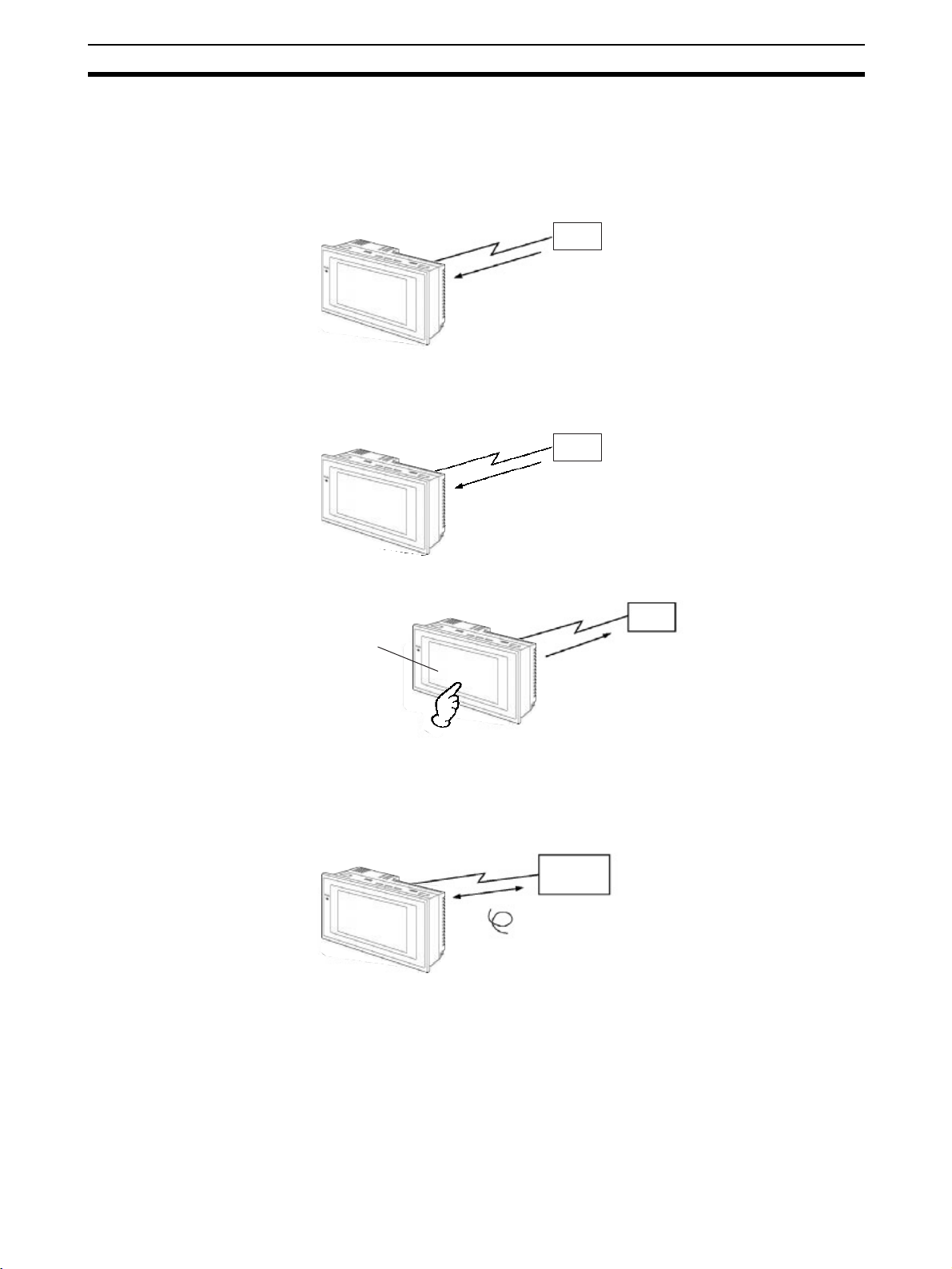
1-1-1 Operations of NT20
Displays Screens The information to be displayed (screen data) can be created on a computer
by using the Support Tool and stored in the NT20. The screen data can be
displayed on the NT20 in response to the instructions from a Host or touch
switch operation.
Host
The screen data designated by
instructions from Host or touch
switch operation is displayed.
Receives Data from a Host The NT20 can be connected to the Host using the host link or NT link commu-
nications method to enable reception of the required data from the Host.
Host link, NT link, RS-232C,
C200H direct communications
Host
Sends Data to a Host Data input through a touch panel can be sent to a Host.
Host
Touch panel
ON/OFF information,
numeric data, etc.
Screen Data The screen data to be displayed on the NT20 can be created by a computer
by using the Support Tool. Connect the NT20 to a PC/AT with an RS-232C
cable so that the screen data are transferred to the NT20.
Create screen data.
RS-232C
Screen data
PC/AT
(Support Tool)
When the host is connected at serial port A,
the personal computer is connected only
when transferring screen data between the
NT20 and NT Support Tool.
3
Page 25

Functions of NT20 Section 1-2
1-2 Functions of NT20
The NT20 has the following features which are different from those of existing
NT20M/NT20S;
1-2-1 Features
Downsized Body • The connectors are located at other than the front.
• The communications cable connectors are housed in the unit so that they
do not protrude from the unit.
• The tool connectors and the Host communications connectors are used in
common (when the host link/NT link is used).
Construction Best Suited to the FA Environment
• Easy-to-read screen even in direct sunlight.
• Long-lived backlight leads free from maintenance.
• Waterproof structure equivalent to oil-resistant IP65.
256 dots
128 dots
Wide angle of visibility ±35°
A Host Link I/F Unit, Screen Data Memory, and a System ROM Are All Incorporated
• With the NT link communications method, 1:1 connections and 1:N connections are possible.
• There is no complicated installation work except a simple connection to a
Host.
• A flash memory is used for the screen data memory. There is no need of
backup battery.
• The following communications methods are standard for each model:
NT20-ST121-E: Host Link (direct) and NT Link
NT20-ST121-E + NT20-IF001 + NT600M-LB122-V1: C200H direct communications
NT20-ST128: RS-232C communications (command control)
• The NT20 can be connected to Mitsubishi FX-series and Mitsubishi Aseries PLCs. (Refer to PLC Connection, Operation Manual (Cat. No.
V042-E1-@)).
Touch Switch Operation The System Menu can be displayed by using the touch switches located in
four corners of the screen.
Compatibility with NT20M/
NT20S
Existing screen data, user programs, are compatible.
4
Page 26
Functions of NT20 Section 1-2
1-2-2 Principal Functions of NT20
Functions Related to the Data Display
• Character display
Characters of various sizes can be displayed. Characters can flash or be highlighted.
• Figure display
Straight lines, circles, and other graphic figures can be displayed.
• Memory data display
Contents of the character-string memory table and the numeral memory table can be
displayed. The memory table contents can be changed from the PLC/Host.
• Bar graph display
Bar graphs corresponding to the contents of the numeral memory table can be displayed.
• Lamp display
Lamps which turn on or flash as controlled by the Host can be displayed.
Functions Related to the Data Input
• Input by the touch switch
Data can be input by simply touching the screen.
• Numeric setting function
The touch keys can be assigned with numeric
values so that the numeric values can be input at
the operation site and sent to the PLC/Host.
Other Functions
• Buzzer
A built-in buzzer can be used.
• Communications with a PLC
By connecting the NT20 with a PLC using the host link, NT link, C200H,
or RS-232C communications method, data can be received from the
host and touch switch status information can be sent to the host.
• System function
The system setting and maintenance can be executed by using the
System Menu on the screen.
• Screen data creation
The screen data can be created by using support tools on the computer
and stored in the unit.
• Unrestricted screen display
When the NT20 is connected to the host via an RS-232C interface,
characters and graphics can be displayed independently of the
registered screens (terminal function) (only with NT20-ST128).
5
Page 27

Functions of NT20 Section 1-2
1-2-3 Comparison between NT20S, NT20M, and NT20
The NT20 is a unitary PT which incorporates a system ROM, screen memory,
and a host I/F unit (Host link, NT link, RS-232C, and C200H direct communications) as the standard equipment in one body.
The NT20 has the following features which are different from those of existing
NT20/NT20S:
Function NT20S NT20M-DT121-V2 NT20
Communications • Host link/NT link incorpo-
Communications connector
Host RUN input terminal/
Alarm output terminal
System keys Not provided Provided Not provided
Contrast control Back Front Back
Waterproof performance Equivalent to oil-resistant
Allowable momentary
power interruption time
System ROM Built in (not replaceable) System ROM compatible with
Resume function Not provided Provided Not provided
History retaining function Not provided Provided Not provided
Screen transfer ❍❍ (Only possible if screen
Screen data compatibility ❍ (Note) – ❍ (Note)
PLC ladder compatibility ❍ – ❍
Backlight replacement ❍ Possible with NT20M-DT131. Do not need
Screen data memory Built in (flash ROM only) Optional (select from
Screen data memory
capacity
Outside dimensions 190 × 110 × 58 mm 220 × 110 × 82 mm 190 × 108 × 53.5 mm
rated NT20S-ST121-EV3
• C200H direct communications incorporated
NT20S-ST122-V1
• RS-232C incorporated
NT20S-ST128
(other host I/F units cannot
be connected)
• The communications connector (9-pin) for a Host is
shared with that for the Support Tool. (NT20S-ST121EV3/ST128)
• Connectors for Support Tool
(9-pin) and Host connections on the rear face
(NT20S-ST122-V1).
Not provided Provided Not provided
IP65
Not guaranteed 5 ms Not guaranteed
96KB 128 KB max. 512 KB
Host I/F units are required. • Host link/NT link
• C200H direct communications
Host I/F unit for C200H communications is required.
• RS-232C incorporated
NT20-ST128 (other host I/F
units can not be connected)
The Support Tool connector
(9-pin) is located on the front.
The Host connector (25-pin)
is located on the back.
Conforms to IP54F. Equivalent to oil-resistant
host I/F unit is required.
data memory is an SRAM)
EPROM, SRAM, and
EEPROM)
• The communications connector (9-pin) for a Host is
shared with that for the Support Tool. (Port A)
• The communications connector (9-pin) for a Host
(Port B)
IP65
Flash ROM rewriteable
❍
Built in (Flash ROM)
Note If a system key function is required on continuous screens or for numerical
setting or buzzer stop, use the Support Tool and set the touch switches which
have the system key function in such screens.
For details, refer to 4-7-3 System Key Functions on page 154.
6
Page 28
Functions of NT20 Section 1-2
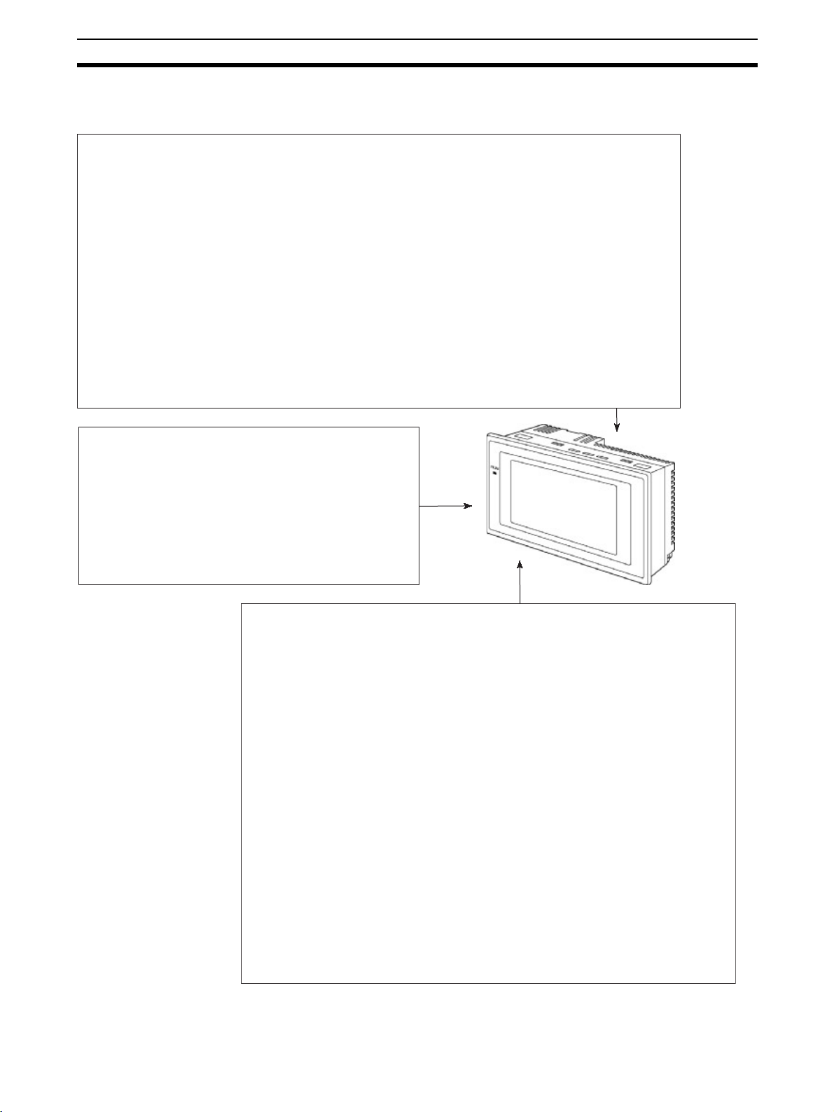
1-2-4 Displays
The NT20 can display various kinds of elements such as characters, lamps,
touch switches, and bar graphs on a screen. The screen data displayed on the
NT20 are created by using the Support Tool on a computer.
Touch switches
Characters
(character string)
Characters (text)
Bar graph
Line 1 Status
Machine name : NT20
Production qty. : 137 units
0% 50% 100%
Stage 1 Stage 2
Emergency
stop
Restart
Stage 3
Numeric value
(Numeral table)
30%
Lamps
Characters (Text) Characters and marks which do not need to be changed can be written
directly to the screen.
Characters (Character-string Memory Table)
Character-strings stored in the character-string memory table are displayed.
The display characters can be changed by changing the data stored in the
character-string memory table.
Numeric Values (Numeral Table)
Numbers stored in the numeral table are displayed. The display numbers can
be changed by changing the data stored in the numeral table. Hexadecimal
values can also be displayed.
Lamps Lamps are displayed as square or round frames and indicate the operating
status. They are controlled by the Host and can be lit (reversed) or made flash
(alternates normal with reversed displays).
Touch Switches Touch switches can be set anywhere on the screen. Touching the screen at a
touch switch location can switch the display (display switch function) or notify
the Host (notification function). The touch switches can be lit or made flash by
controlling from the Host in the same way as the lamps.
Numeric Keys These are the touch switches used to input numeric values.
Bar Graphs The bar graph extends and contracts in proportion to the data stored in the
numeral table. A percentage value can also be displayed simultaneously.
Marks Marks can be designed, created, and handled like characters by the user.
7
Page 29

Method for Connection to the Host Section 1-3
1-3 Method for Connection to the Host
This section describes the methods for connection to the host used with the
NT20, and the relationship between the connection method and the communications method.
NT20 Communications Ports and Communications Methods
The NT20 has two communications ports. Their uses are indicated in the
table below.
Communications
Port
Serial port A Host Link
Serial port B Host Link
Usable Communications
Methods
1:1 NT Link
1:N NT Link (See note.)
RS-232C (command control) (NT-
20-ST128)
(NT Support Tool connection)
1:1 NT Link
1:N NT Link (See note.)
RS-232C (command control) (NT-
20-ST128)
Communications
RS-232C
RS-232C
Note There are two 1:N NT Link communications rates: standard and high-speed.
Converting Communications Type with the RS-232C/RS-422A Link
Adapter and RS-422A Converter
An OMRON NT-AL001 Link Adapter or CJ1W-CIF11 RS-422A Converter can
be used convert from RS-232C communications to either RS-422A or RS-
485.
• RS-232C
•
RS-232C ⇔ RS-485
⇔ RS-422A
There are two models of Link Adapter/RS-422A Converter are available. They
provide different features:
• NT-AL001 Link Adapter
The RS-232C port is insulated from the RS-422A/485 terminals. An RS232C cable (2 m max.) can be connected to either serial port A or B on
the NT20.
• CJ1W-CIF11 RS-422A Converter
The RS-232C port is not insulated from the RS-422A/485 terminals. The
CJ1W-CIF11 RS-422A Converter can be connected to either serial port A
or B on the NT20.
• Communications Distance
Use the NT-AL001 if the communications distance exceeds 50 m.
8
Page 30
Method for Connection to the Host Section 1-3
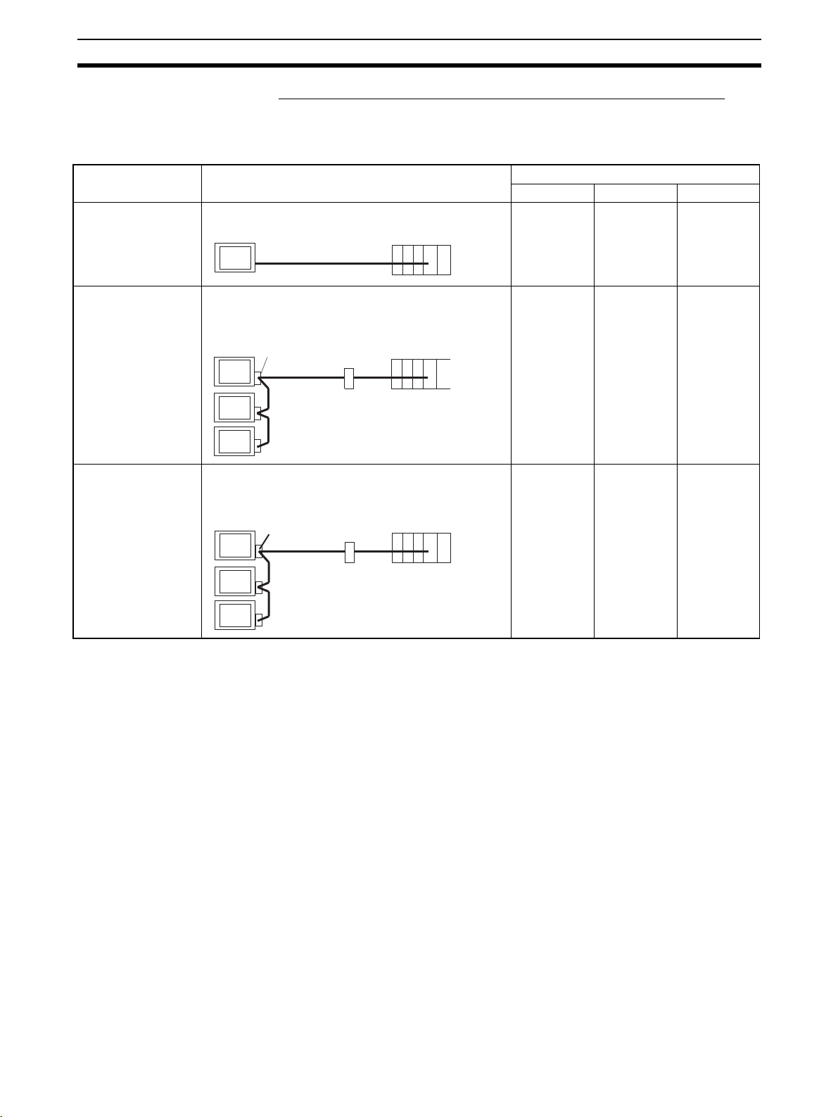
Combinations of Communications Method and Connection Method
The connection methods that can be used depending on the communications
method used and the communications type for communications between the
NT20 and the host are indicated in the table below.
Communications
type at Host
RS-232C ❍❍❍
RS-232C ××❍
Direct 1:1 connection
PT
1:N connection with RS-422A through
Usable Connection Method Usable Communications Method
Host Link 1:1 NT Link 1:N NT Link
Host
RS-232C (15 m max.)
Link Adapter and RS-422A Converters
NT-AL001 (See note 1.)
or CJ1W-CIF11 RS-
PT
422A Converter NT-AL001
RS-422A
(total length 500 m,
See note 2.)
RS-232C ××❍
1:N connection with RS-485 through
Link Adapter
RS-232C
(2 m max.)
Host
Link Adapter and RS-422A Converters
NT-AL001 (See note
1.) or CJ1W-CIF11
PT
RS-422A Converter
NT-AL001
Link Adapter
RS-485
(total length 500 m,
See note 2.)
RS-232C
(2 m max.)
Host
❍: Connection possible
×: Connection not possible
Note (1) An RS-232C Cable (not shown in the diagram) is required when connect-
ing an NT-AL001 Link Adapter to a PT.
(2) If the CJ1W-CIF11 is used, the total communications distance is 50 m.
This also applies if both the NT-AL001 and CJ1W-CIF11 are used in the
same communications path.
9
Page 31

Communications with PLC by Direct Connection Section 1-4
1-4 Communications with PLC by Direct Connection
1-4-1 Functions of the Allocated Bits and Words
When using an NT20-ST121@ with the direct connection function (host link or
NT link), the elements displayed on the NT20 and the NT20 status can be
allocated to the bits and words of the PLC. By changing the contents of the
bits and words, the NT20 can be controlled by the PLC. It is also possible to
send data to the PLC by pressing the touch switches on the NT20.
• Controlling the NT20 by a PLC
The following NT20 functions can be controlled by a PLC.
Screens: Display of designated screens, confirmation
of screen numbers, etc.
Memory tables: Writing to a memory table, copying from a
memory table entry to another memory table
entry, etc.
Lamps and touch switches: Display instructions, confirmation of display
status, etc.
System control: Buzzer ON/OFF, backlight ON/OFF, and oth-
er NT20 status
• Notifying the PLC from the NT20
Data in the NT20 is sent to a PLC when a touch switch is pressed. The fol-
lowing types of data are sent to a PLC.
• NT20 status
• Touch switch status
• Numerical values input with touch switches by using the numeral setting function
• Changes in a memory table after copying between memory table entries
Functions of Display Elements
• Lamps
Allocation destination: Bit
Lamp #1 (Bit 000100)
Lit
Unlit
Lamp #2 (Bit 000101)
PLC’s bit status is displayed by the “Lamp” on the NT20.
The lamp comes on (flashes) when the PLC’s bit status (lamp bit) is ON
(1), and goes off when it is OFF (0).
NT20
PLC
Switch 1: ON (Bit 000100)
Switch 2: OFF (Bit 000101)
10
Page 32

Communications with PLC by Direct Connection Section 1-4
)
• Touch Switches
Allocation Destination: Bit
Touch switch
12 Bit 009012
The lamp comes on (flashes) when the PLC’s control bit is ON (1) and
goes off when it is OFF (0). When the touch switch is pressed, the PLC’s
notification bit comes ON (1) or goes OFF (0).
• Numeral Memory Table
Allocation destination: Word
Numeral memory
table entry 1 (TIM003)
NT20
Bit 009012: ON
NT20
PLC
PLC
Numeral memory table entry 150 (word 0005
Allocate the numeral memory table entries to arbitrary words in the PLC. If
word contents change when corresponding numeral memory table entry is
displayed on the screen, the value on the screen will also change. Monitoring of words can also be made easily.
Reading and writing are executed so that the contents of allocated words
and contents of numeral memory table entries are always the same during
display.
• Character-string Memory Table
Allocation destination: Word
NT20
Character-string memory table entry 1
Allocated word number: 3
First word: DM0100
PLC
("a", "b")
("c", "d")
("e", "f")
Allocate character-string memory table entries to arbitrary words in the
PLC. If word contents change when corresponding character-string memory table entry is displayed on the screen, the value on the screen will also
change. Messages can be displayed easily.
Reading and writing are executed so that the contents of allocated words
and contents of character string memory table entries are always the same
during display.
11
Page 33

Communications with PLC by Direct Connection Section 1-4
y
Functions of the PT Status Control Area (PLC to NT20)
The “PT status control area” is used to control the NT20 status. When data is
written to this area in the PLC, the NT20 reads the contents and operates
according to the contents.
Example of the PT Status Control Area Application
When data is written to the PT status control area, the NT20 will operate as
given below.
Continuous
buzzer sound
Screen 3
display
Numeral memory table entry 50
NT20
PLC
PT status control area
Screen switch setting
Memory table entry
Copy setting
PT status control bits
Copy
Numeral memory table entry 7
Functions of the PT Status Notify Area (NT20 to PLC)
The “PT status notify area” is used to notify the PLC of changes of the NT20
status. When a change is made in the NT20 status, the change is written to
this area in the PLC. By reading the data from the area, the NT20 status can
be checked.
Example of the PT Status Notify Area Application
When a change is made in the NT20 status, such change will be indicated in
the PT status notify area as described below.
PLC
PT status notify area
Allocated word (numeral table entry 13)
12345678
12345678
NT20
Numeral memory table entry 13
12345678
1-4-2 Connecting to PLC from Other Companies
Currently display screen
Updated memory table entr
PT status
Start
Start + 1
The NT20 can be connected to PLCs from other companies using the computer link method.
Connectable PLCs The NT20 can be connected to the following PLCs.
• Mitsubishi A-series Sequencers (via Computer Link Unit)
• Mitsubishi FX-series Sequencers
Refer to the PLC Connection Manual (Cat. No. V042) for connection methods.
NT Series Support
Software
The following Support Software is required when connecting PLCs from other
companies.
Support Software: NT-ZJCAT1-EV4(S) (NT Series Support Software for
Windows, Version 4.@)
12
Page 34

Communications Using RS-232C (NT20-ST128) Section 1-5
1-5 Communications Using RS-232C (NT20-ST128)
This section gives a brief description of the NT20 control commands sent from
the host through the RS-232C interface when the NT20-ST128 is used.
For details on each of the commands sent through the RS-232C interface,
refer toSECTION 6 Using RS-232C Communications.
Control of the NT20 by a Host is executed by two kinds of commands supported by the RS-232C interface that is built into the NT20.
Operation Commands Operation commands are used to control the display and status of the running
NT20 as well as to provide notification.
They are used for purposes such as screen display, data writing, and enqui-
ries.
Notification of the NT20 operation contents can be provided to the Host.
Terminal Commands Terminal commands are used to use the NT20 as a display terminal of the
Host.
When the NT20 is used as a display terminal, it can display characters and
figures according to instructions given by the Host, independently of the
screens registered to the NT20.
These commands are also used if unexpected problems occur.
13
Page 35

Before Operating Section 1-6
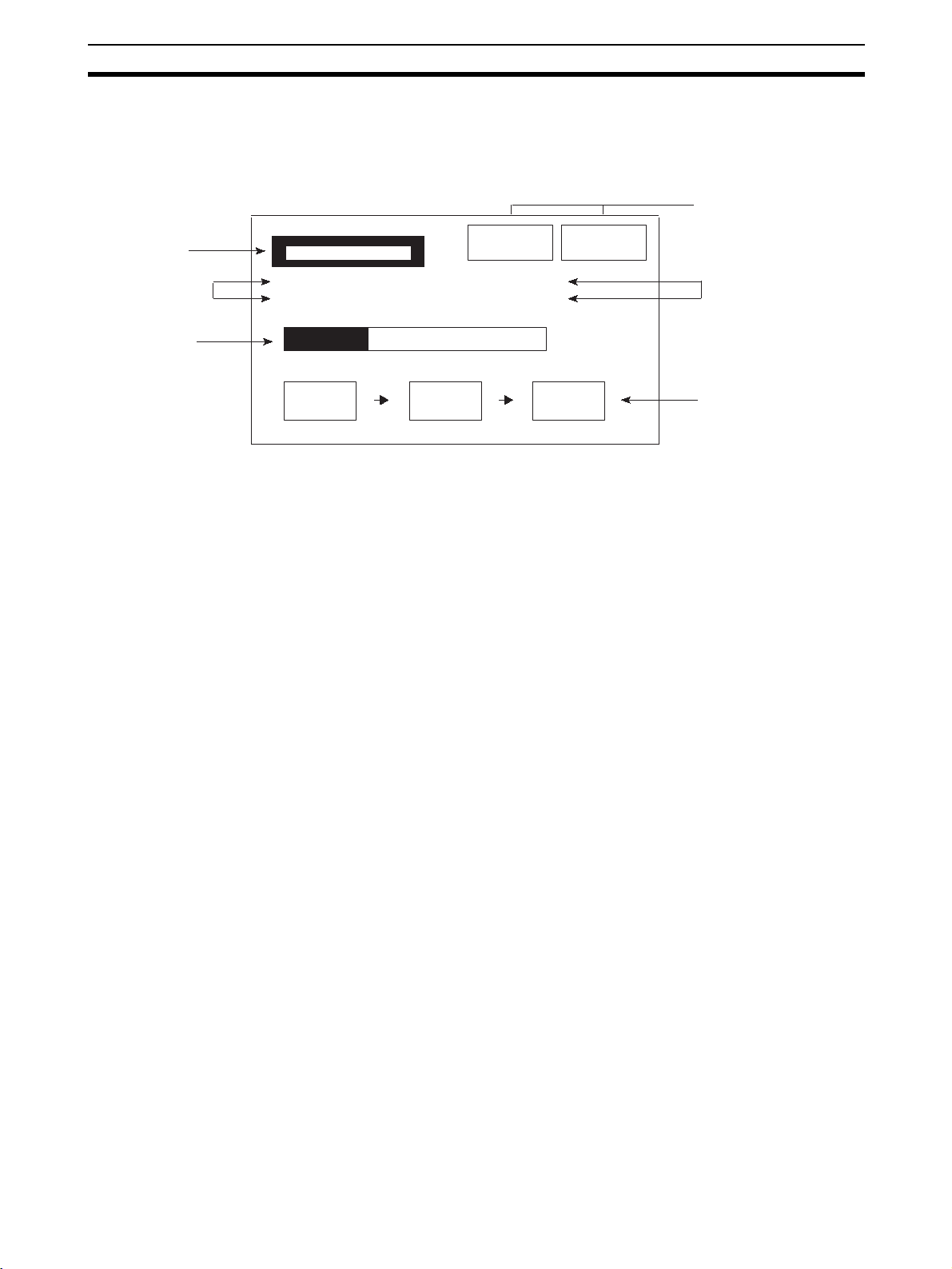
1-6 Before Operating
Follow the procedure given below to start the system of the NT20.
Host
Set the host settings.
• For the Host Link, refer
to page 44, and the manuals for the Host Link
Unit and Programming
Device.
• For a 1:1 NT Link, refer
to page 56.
• For 1:N NT Links, refer to
page 60.
• For high-speed 1:N NT
Links, refer to page 65.
• When using C200H
direct communications,
no settings are required.
• For RS-232C, refer to
page 79 and the manuals for the Host.
Connect to the NT20.
NT20
Set the DIP switch pins.
(page 19)
Install the PT in the
operation panel.
(page 22)
Connect the power supply
and peripheral device.
(page 23)
Install the system program.
(See note.)
(Refer to page 126 and the NT
Support Tool operation manual.)
Transmit the screen data.
Set the memory switches.
(page 91)
Connect to the host.
NT Support Tool
Install the NT Support
Tool in the computer.
(Refer to the NT Support Tool
Operation Manual.)
Create the screens.
(Refer to the NT Support Tool
Operation Manual.)
(page 102)
Create the host program.
Start operation.
Confirm the settings and
check communications.
Note System program installation is only done in special circumstances, for exam-
ple when changing the system program, or when recovering the original status of the installed program. This operation is not normally necessary.
14
Page 36

Before Operating Section 1-6
Refer to the following manuals for the equipment and software.
Device or Software Manual Title Cat. No.
NT20 User’s Manual V091-E1-@
System Installer NT-series Support Tool for Windows (Ver. 4.8) Operation Manual V061-E1-@
NT Support Tool NT-series Support Tool for Windows (Ver. 4.8) Operation Manual V061-E1-@
PLC SYSMAC CPM1 Operation Manual W262-E1-@
SYSMAC CPM1A Operation Manual W317-E1-@
SYSMAC CPM2A Operation Manual W352-E1-@
SYSMAC CPM2C Operation Manual W356-E1-@
SYSMAC C200H Operation Manual (for CPU01/03/11) (Programming) W130-E1-@
SYSMAC C200H Operation Manual (for CPU21/23/31) (Programming) W217-E1-@
SYSMAC C200HS Installation Guide W236-E1-@
SYSMAC C200HS Operation Manual (Programming) W235-E1-@
SYSMAC C200HX/HG/HE (-Z) Installation Guide W302-E1-@
SYSMAC C200HX/HG/HE Operation Manual W303-E1-@
SYSMAC C200HX/HG/HE-Z Operation Manual W322-E1-@
SYSMAC CQM1/CPM1/CPM1A/SRM1 Programming Manual W228-E1-@
SYSMAC CQM1H Operation Manual W363-E1-@
SYSMAC CVM1/CV500/CV1000/CV2000/CVM1 Operation Manual: Ladder Dia-
grams
CS Series Programmable Controllers Operation Manual W339-E1-@
CJ Series CJ1G-CPU@@-E Programmable Controllers Operation Manual W393-E1-@
CS/CJ Series Programming Manual W394-E1-@
CS/CJ Series Serial Communications Boards/Units Operation Manual W336-E1-@
SYSMAC CQM1H Series Serial Communications Board Operation Manual W365-E1-@
CompoBus Master
Control Unit
Programming Tools SYSMAC Support Software Operation Manual: C-series PLCs W248-E1-@
Host Link Unit/
Serial Communications Board
SRM1 (-V2) Operation Manual W318-E1-@
SYSMAC Support Software Operation Manual: CVM1 PLCs W249-E1-@
SYSMAC CPT User Manual and Quick Start Guide W332-E1-@
CX-Programmer Ver. 4 User Manual W425-E1-@
SYSMAC C Series Host Link Unit System Manual W143-E1-@
SYSMAC CVM1/CV Series Host Link Operation Manual W205-E1-@
SYSMAC C200HW-COM01 C200HW-COM02-V1 to C200HW-COM06-EV1 Com-
munications Board Operation Manual
W202-E1-@
W333-E1-@
W304-E1-@
15
Page 37

Before Operating Section 1-6
16
Page 38

Hardware Settings and Connections
This section describes the settings of the NT20, connections to a Host, and other hardware settings.
2-1 Description of Parts and Settings . . . . . . . . . . . . . . . . . . . . . . . . . . . . . . . . . . 18
2-1-1 Description of Parts . . . . . . . . . . . . . . . . . . . . . . . . . . . . . . . . . . . . . 18
2-1-2 Operation Status DIP Switch Settings . . . . . . . . . . . . . . . . . . . . . . . 19
2-2 Installation. . . . . . . . . . . . . . . . . . . . . . . . . . . . . . . . . . . . . . . . . . . . . . . . . . . . 21
2-2-1 Installation Environment. . . . . . . . . . . . . . . . . . . . . . . . . . . . . . . . . . 21
2-2-2 Installation to the Operation Panel . . . . . . . . . . . . . . . . . . . . . . . . . . 22
2-2-3 Power Supply Connection . . . . . . . . . . . . . . . . . . . . . . . . . . . . . . . . 23
2-3 Connecting Link Adapters and RS-422A Converters. . . . . . . . . . . . . . . . . . . 24
2-3-1 Connecting an CJ1W-CIF11 RS-422A Converter . . . . . . . . . . . . . . 24
2-3-2 Connecting an NT-AL001 Link Adapter . . . . . . . . . . . . . . . . . . . . . 28
2-4 Connecting the NT Support Tool . . . . . . . . . . . . . . . . . . . . . . . . . . . . . . . . . . 35
2-5 Using a Memory Unit . . . . . . . . . . . . . . . . . . . . . . . . . . . . . . . . . . . . . . . . . . . 36
2-5-1 Installation Method. . . . . . . . . . . . . . . . . . . . . . . . . . . . . . . . . . . . . . 37
2-5-2 Method of Use . . . . . . . . . . . . . . . . . . . . . . . . . . . . . . . . . . . . . . . . . 37
2-6 Connecting to the RS-232C Port at the Host . . . . . . . . . . . . . . . . . . . . . . . . . 44
2-6-1 Host Types and Settings . . . . . . . . . . . . . . . . . . . . . . . . . . . . . . . . . . 44
2-6-2 Connecting Directly between RS-232C Ports . . . . . . . . . . . . . . . . . 69
2-7 Communicating with the PLC Using C200H Direct Communications . . . . . 73
2-7-1 Applicable PLC Units. . . . . . . . . . . . . . . . . . . . . . . . . . . . . . . . . . . . 73
2-7-2 Connection Method . . . . . . . . . . . . . . . . . . . . . . . . . . . . . . . . . . . . . 73
2-7-3 Turning the Power ON/OFF When Using C200H Direct
Communications. . . . . . . . . . . . . . . . . . . . . . . . . . . . . . . . . . . . . . . . 77
2-8 Host Connections by RS-232C (NT20-ST128) . . . . . . . . . . . . . . . . . . . . . . . 79
2-8-1 Host Computer Communications Settings . . . . . . . . . . . . . . . . . . . . 79
2-8-2 Connector Pin Arrangement . . . . . . . . . . . . . . . . . . . . . . . . . . . . . . . 79
SECTION 2
17
Page 39

Description of Parts and Settings Section 2-1
Note On unpacking the NT20 and peripheral devices, check their external appear-
ance and confirm that there is no damage. Also confirm that there is no abnormal noise when you shake the PT lightly.
2-1 Description of Parts and Settings
Before getting to the operation, confirm the names and functions of parts.
Also set the DIP switches on the NT20.
2-1-1 Description of Parts
Front View
Rear View
RUN indicator
Lit green while the PT is in
•
RUN mode.
Touch switches can be created
in the desired locations on the
display and used as lamps,
input switches, and other
functional objects.
Note The NT20 comes in two body colors.
• NT20-ST121-E: Ivory
• NT20-ST121B-E: Black
• NT20-ST128: Ivory
• NT20-ST128B: Black
Expansion interface connector
When using an Expansion Interface Unit
such as a Memory Unit, connect it here.
Battery cover
There is a battery holder beneath this
cover. The Battery is not installed when the
PT is shipped.
Type name
Contrast control
Use a fine flat-blade screwdriver.
Reset switch
DIP switch
18
Power input terminals
Connect the power to the NT20 at
these terminals
Serial port A connector
Connect this connector to a host or to
a computer running Support Software.
An RS-232C 9-pin connector is
required. A CJ1W-CIF11 RS-422A
Converter can be connected directly.
Serial port B connector
Connect this connector to communicate with a
host. An RS-232C 9-pin connector is required. A
CJ1W-CIF11 RS-422A Converter can be
connected directly.
Page 40

Description of Parts and Settings Section 2-1
2-1-2 Operation Status DIP Switch Settings
Set the NT20 operation status with the DIP switches located in the bottom
right corner on the rear of the body.
Switch # Function
SW2-1 Screen data forced initialize effective/ineffective
Note When this switch is ON, SW2-4, SW2-5 and SW2-6 must be OFF.
ON The NT20 will start in a special RUN mode in which the screen data memory is initialized. When it
is started, the memory initialization menu will be displayed. For the initialization procedure, refer to
Section 3-4 Initializing Memory.
[OFF] The NT20 will start in normal RUN mode.
SW2-2 Screen display language mode. DIP SW2-2 is used to indicate language selection. If it is turned ON, then dis-
SW2-3 Switching to the System Menu enabled/disabled
SW2-4 Unused (Reserved for system use)
SW2-5 System resource initialize
SW2-6 System program initialize
play language will use English and the language parameter in memory SW is not selectable (User can't
choose other language than English.) But if it is turned OFF, then user can choose other language through
language parameter in memory SW.
[ON] Messages are displayed in English.
OFF Language can be selected.
ON The System Menu cannot be displayed. If an error occurs during a start-up, the System Menu will
be automatically displayed. However, “transfer mode” cannot be entered.
[OFF] The System Menu can be displayed.
Note When this switch is ON, SW2-1, SW2-4 and SW2-6 must be OFF.
ON Effective
[OFF] Invalid
Note When this switch is ON, SW2-1, SW2-4 and SW2-5 must be OFF.
ON Effective
[OFF] Invalid
[ ] indicates factory setting.
!Caution If the DIP switch settings have been changed when the NT20 is powered,
reset the power to the NT20. The changes with the DIP switches become
effective only after the power supply is reset.
Note (1) ln addition to the DIP switches, set also the “communications type”, “host
link baud rate”, etc. at the memory switches when host link/NT link is
used.
For these settings, refer to Section 3-5 Setting the Conditions of Commu-
nications with the Host by Using the Memory Switches (page 91).
(2) It may be necessary to change the DIP switch settings after installing the
NT20 in an operation panel. Bear this in mind when deciding the installa-
19
Page 41

Description of Parts and Settings Section 2-1
tion position.
During work at the panel, take care to ensure that no metal scraps enter
the unit.
20
Page 42

Installation Section 2-2
2-2 Installation
Install the NT20 to the operation panel and connect the power to the NT20 as
described below.
2-2-1 Installation Environment
Observe the following points when installing the PT in an operation panel.
!Caution Do not install the NT20 at sites subject to the following conditions.
Otherwise, the product may malfunction.
• Severe temperature variations
• Temperatures or humidities outside the ranges stated in the specifications
• High humidity, condensation
• Splashing chemical agents
• Severe oil splashing
• Corrosive or flammable gases
• Strong vibrations or shocks
• Direct exposure to wind and rain (outdoor sites)
• Strong ultra-violet irradiation
Take adequate measures to ensure shielding if the NT20 is used at a location
subject to any of the following conditions.
• Static electricity, or noise from other equipment
• Strong electric or magnetic fields
• Nearby power cables
• Potential exposure to radioactivity
!Caution Do not perform a withstand voltage test. Performing with stand voltage tests
may result in malfunction.
21
Page 43

Installation Section 2-2
2-2-2 Installation to the Operation Panel
The NT20 can be flush mounted to an operation panel.
Use the panel fittings and tools included in the product package and follow the
procedure below.
!Caution During work at the panel, take care to ensure that no metal scraps enter the
unit. Otherwise, the product may malfunction.
Note The thickness of applicable operation panel is 1.6 mm to 4.8 mm. All fittings
must be tightened uniformly to a torque of at least 0.5 to 0.6 N·cm in order to
ensure water- and dust-resistance. The panel must not be soiled or warped,
and must be able to support an installation that will remain secure and strong.
1. Open a hole, shown below, in the panel and install the NT20 from the front
of the panel.
+0.5 mm
98.5
0 mm
+0.5 mm
178.5
0 mm
2. Attach the panel fittings at four positions, shown below, on the rear of the
NT20.
Fit the hook of the fitting in the square hole in the body and tighten the
screw with a Phillips head screwdriver while lightly pulling the fitting.
Note In order to ensure adequate water and dustproof performance, tighten the four
panel fittings uniformly and make sure there are no gaps between the fittings
and the NT20 panel.
22
Page 44

Installation Section 2-2
2-2-3 Power Supply Connection
Connect a 24 VDC power supply to the power input terminals.
!Caution Carefully check the wiring before turning ON the power.
!Caution Do not connect AC power to the DC terminals. Incorrect wiring may result in
burning.
Note (1) Depending on how the power is turned ON/OFF, the entire system may
stop. Follow the correct procedure when turning the power ON/OFF. Otherwise the system may operate unpredictably.
(2) Use DC power supplies with low voltage fluctuation. An incorrect power
supply may result in malfunctions.
(3) Do not perform a dielectric strength test. Otherwise, the product may mal-
function.
(4) If complying with EC directives (low voltage directives), use a power sup-
ply with reinforced insulation (compliance with EC directives is planned
for June 1998).
24 V
DC
NC
Circuit
breaker
24 VDC
power supply
Power Supply
The applicable power supply specifications are as follows.
Item Value
Power supply 24 VDC
Allowable power supply voltage fluctuation range 20.4 VDC to 27.6 VDC
(24 VDC −15%, +15%)
Power supply voltage capacity 10 W or more
Parts Used for Connection
Note For the connection to the power supply terminal block, use stranded wire of
2
2mm
or greater cross sectional Area (14 AWG stranded wire) and M3.5 size
crimp terminals.
Tighten the screws on the terminal block to a torque of 0.8 N
⋅m.
Otherwise the product may malfunction.
Fork type Round type
7 mm or less 7 mm or less
Recommended Terminals
Maker Fork type Round type Stranded wire
Japan Solderless Terminal MFG 2-YS3A 2-3.5
Fuji Terminal 2-YAS3.5 V2-S3.5
Nichifu Terminal 2Y-3.5 2-3.5
size
2.0 to 2.63 mm
(14 to 13 AWG)
2
23
Page 45

Connecting Link Adapters and RS-422A Converters Section 2-3
2-3 Connecting Link Adapters and RS-422A Converters
This section describes the installation of the NT-AL001 Link Adapter and
CJ1W-CIF11 RS-422A Converter, including the external dimensions, procedure for mounting and removal, and specifications. Refer to this information
when designing the control panel. For further details, refer to the Instruction
Sheet supplied with the NT-AL001 or CJ1W-CIF11.
2-3-1 Connecting an CJ1W-CIF11 RS-422A Converter
The CJ1W-CIF11 RS-422A Converter connects directly to the NT20’s serial
port A or B and converts RS-232C communications to RS-422A or RS-485.
The NT20 supplies power to the RS-422A Converter through pin 6 of the RS232C connector, so an external power supply is not required.
Note 1. The RS-232C connector is not insulated from the RS-422A/RS-485 con-
nector within the CJ1W-CIF11 RS-422A Converter. If there are concerns
about differences in ground potential or noise, we recommend using the
NT-AL001 Link Adapter.
2. Always turn OFF the NT20’s power supply before installing/removing a RS422A Converter or connecting/disconnecting cables.
3. Always discharge any static electricity by touching a grounded object before installing the RS-422A Converter or connecting cables.
Specifications
General Specifications
Item Specification
Dimensions 18.2 × 34.0 × 38.8 mm (W × H × D)
Weight 20 g max.
Ambient operating temperature 0 to 55°C
Ambient storage temperature –20 to 75°C
Ambient operating humidity 10% to 90% (with no condensation)
Rated power supply voltage 5 V (Supplied from pin 6 of the RS-232C connecCurrent consumption 40 mA max.
Operating atmosphere No corrosive gases
Vibration resistance Same as NT20 Series.
Shock resistance Same as NT20 Series.
Isolation method Not isolated
Maximum communications distance 50 m (Use the NT-AL001 if the total communications distance exceeds 50 m.)
RS-232C Connector
Connector Pin Arrangement for
RS-232C Port
Pin number Signal
1FG
2RD
3SD
4CS
5RS
6+5V
7, 8 NC
9SG
Hood NC
tor.)
24
Page 46

Connecting Link Adapters and RS-422A Converters Section 2-3
Note The hood will have the same electrical potential as the connector on the other
end of the cable.
RS-422A/485 Terminal
Block
Signal
RDA–
RDB+
SDA–
SDB+
FG
Block Diagram
SD
RS
CS
RD
ER
DR
SV
SG
FG
SW.6
SW.5
DIP Switch Settings
Pin
number
1 Terminating resistance With (at both ends of the commu-
2 Two-wire/four-wire method selec-
tion (See note 1.)
3 Two-wire/four-wire method selec-
tion (See note 1.)
4 Not used. --- --5 Selection of RS control for RD
(See note 2.)
6 Selection of RS control for SD
(See note 3.)
Function ON OFF
nications path)
Two-wire method Four-wire method
Two-wire method Four-wire method
With RS control Without RS control (always ready
With RS control Without RS control (always ready
SW.2SW.3 SW.1
Without
to receive)
to send)
SDB(+)
SDA(-)
RDB(+)
RDA(-)
FG
Note (1) Set pins 2 and 3 to the same setting. (ON for the two-wire method or OFF
for the four-wire method.)
(2) To prohibit echoback, set pin 5 to ON (with RS control).
25
Page 47

Connecting Link Adapters and RS-422A Converters Section 2-3
(3) When connecting to several devices using the four-wire method in a 1:N
connection, set pin 6 to ON (with RS control). When connecting using the
two-wire method, set pin 6 to ON (with RS control).
Dimensions
5.8
34.0
38.8 18.2
DIP Switch Settings,
Wiring, and Installation
The DIP switch settings must be changed to perform communications according to settings other than the default settings.
1. Remove the DIP switch cover using a flat-bladed screwdriver in the way
shown below.
Note Press the cover gently while removing it to prevent it from popping out sud-
denly.
2. Using a fine pair of tweezers or other tool with a fine point, change the settings of the DIP switch pins to match the desired communications conditions.
3. Be sure to remount the cover after finishing the DIP switch settings.
Wiring the RS-422A/485
Termina l Block
26
1
2
3
4
5
6
O
N
O
N
All the pins are factory-set to OFF.
• Use either two-wire or four-wire shielded cable.
Recommended cable: CO-HC-ESV-3P
×7/0.2 (Hirakawa Hewtech)
Page 48

Connecting Link Adapters and RS-422A Converters Section 2-3
• Connect the shield wire at both ends of the cable carrying RS-422A/485
signals to ground, and ground the ground terminal on the Power Supply
Unit of the CPU or Expansion Rack to 100
1. Taking care not to damage the shield, strip between 30 and 80 mm of
sheath off the end of the cable.
30 to 80 mm
2. Carefully twist the shield mesh together to form a single wire, and carefully
cut off the material surrounding the signal wires and any unnecessary signal wires.
3. Strip the sheath off the signal wires to a length sufficient to attach crimp
terminals. Apply vinyl tape or heat–shrinking tube to the sheathes and
stripped parts of communications lines.
4. Attach stick-type crimp terminals to ends of the signal lines and crimp them
using a crimp tool.
• Recommend crimp terminals:
Phoenix Contact
AI Series
AI-0.5-8WH-B (serial number: 3201369)
• Recommended crimp tool:
Phoenix Contact ZA3
Ω max.
With four-wire cables, insert two signal lines into each crimp terminal together
before crimping.
• Recommend crimp terminals:
Phoenix Contact
AI Series
AI-TWIN2
• Recommended crimp tool:
Phoenix Contact
UD6 (serial number: 1204436)
5. Connect the signal lines and the shield line to the RS-422A/485 terminal
block.
×0.5-8WH (serial number: 3200933)
27
Page 49

Connecting Link Adapters and RS-422A Converters Section 2-3
RS-422A/485 Cable Shield
Connections
When using the CJ1W-CIF11 (with or without the NT-AL001), connect the signal lines, shields, and grounds as shown in the following diagram.
CPU Rack
CPU Unit
Power
Supply
Unit
LG
GR
PT
CJ1W-CIF11
PT
CJ1W-CIF11
RS-422A/485 shield
connected at both ends
Signal line
or Communications
Unit
CJ1W-CIF11
2-3-2 Connecting an NT-AL001 Link Adapter
The NS-AL001 Link Adapter connects to serial port A or B of the NT20 with an
RS-232C cable and converts the RS-232C communications to RS-422A or
RS-485. (Serial ports A and B cannot be used simultaneously.)
The NT20 supplies +5 V power (150 mA max.) to the Link Adapter through pin
6 of the RS-232C connector, so an external power supply is not required.
Note 1. The RS-232C connector is insulated from the RS-422A/RS-485 connector
within the NT-AL001 Link Adapter.
2. Always turn OFF the NT20’s power supply before installing/removing a
Link Adapter or connecting/disconnecting cables.
28
PT
Page 50

Connecting Link Adapters and RS-422A Converters Section 2-3
Dimensions The following diagram shows the dimensions of the NT-AL001 Link Adapter.
All dimensions are in mm.
53.5
(2.11)
110 (4.33)
R
NT-AL001-E
om on
4 (0.16)
30 (1.18)
74.5 (2.93)
100.2 (3.94)
105 (4.13) max.
(30)
(1.18)
45 (1.77)
Units: mm (inch)
Dimensions with RS-422A Terminal Block Cover Closed
30 × 114 × 100.2 mm (W × H × D)
Dimensions with RS-422A Terminal Block Cover Open
30 × 114 × 119.5 mm (W × H × D)
Installation and Removal The NT-AL001 Link Adapter can be mounted on a DIN Track or in a control
panel. The Link Adapter’s RS-422A terminal block can be removed easily.
Mounting to a DIN Track
Latch the hook (a) on the rear of the Link Adapter onto the top edge of the DIN
Track, and pivot the Link Adapter downwards (b) as shown in the diagram
below.
Next, fit End Plates at the right and left of the Link Adapter to secure it so that
it cannot shift laterally.
(a)
(b)
29
Page 51

Connecting Link Adapters and RS-422A Converters Section 2-3
Removal from a DIN Track
Remove the End Plates from the right and left of the Link Adapter, insert a flat
blade screwdriver into the catch at the bottom of the Link Adapter, and pull it
down to release the catch.
Mounting to a Control Panel
The control panel must be at least 2 mm (5/64 inch) thick. Drill two mounting
screw holes in a control panel and secure the Link Adapter with screws.
30
(1.18)
100
(3.94)
21
(0.83)
110
(4.33)
2-M4 holes
Units: mm (inch)
Note The control panel must be at least 2 mm (5/64 inch) thick for a secure and
strong mount.
Specifications The following tables list the NT-AL001 Link Adapter’s general and communica-
tions specifications.
General Specifications
Item Specification
Dimensions With RS-422A terminal block cover closed:
30 × 114 × 100.2 mm (W × H × D)
With RS-422A terminal block cover open:
30 × 114 × 119.5 mm (W × H × D)
Weight 200 g max.
Ambient tem-
perature
Operating ambient humidity 10% to 90% (with no condensation)
Rated power supply voltage +5 V ± 10%
Rated power supply current 150 mA max.
Inrush current 0.8 A max.
Insulation resistance 20 MΩ min., measured between the RS-422A termi-
Operating 0 to 55°C
Storage –20 to 75°C
(through pin 6 of the RS-232C connector)
nal signal lines and FG terminal (at 500 VDC)
30
Page 52

Connecting Link Adapters and RS-422A Converters Section 2-3
Item Specification
Dielectric strength 1,500 VAC for 1 minute between the RS-422A termi-
Operating environment No corrosive gases
Vibration resistance Conforms to JIS C0911, 60 minutes each in X, Y, and
Shock resistance
Communications Specifications (RS-232C Interface)
Item Specification
Baud rate 115.2k bps max.
Transmission distance 2 m max.
Connector 9-pin D-SUB connector (female)
Communications Specifications (RS-422A/485 Interface)
Item Specification
Baud rate 115.2k bps max. (depends on the RS-232C baud
Transmission distance 500 m max.
Terminal block configuration 8-terminal detachable terminal block, M3.0
nal signal lines and the FG terminal
Leakage current: 10 mA max.
Z directions
2
Conforms to JIS C0912, 147 m/s
Y, and Z directions
rate)
, 3 times each in X,
31
Page 53

Connecting Link Adapters and RS-422A Converters Section 2-3
DIP Switch Settings The NT-AL001 Link Adapter has a 6-pin DIP switch that sets the RS-422A/
RS-485 communications conditions. Set the DIP switch before connecting the
communications cable.
ON
1 2 3 4 5 6
(Factory settings)
NT-AL001-E
R
om on
SW1-1: Not used (always ON)
SW1-2: Built-in terminator setting
- OFF Terminator not set
- ON Terminator set
SW1-3 and SW1-4: 2-wire/4-wire
SW1-5 and SW1-6: RS-422A send mode
SW1-3 SW1-4
OFF
ON
SW1-3 SW1-4
OFF
ON
SW1-5 SW1-6
OFF
ON
SW1-5 SW1-6
OFF
ON
SW1-5 SW1-6
OFF
ON
2-wire (RS-485)
4-wire (RS-422A)
No RS/CS control
RS-232C CS control (high)
(Data sent at CS high)
RS-232C CS control (low)
(Data sent at CS low)
32
When using Host Link or 1:1 NT Link communications, set the RS-422A send
mode to “no RS/CS control” by turn OFF both SW1-5 and SW1-6.
When using 1:N NT Link communications (standard or high-speed), set the
communications mode to “RS/CS control” by turning ON either pin SW1-5 or
SW1-6.
Note 1. Do not turn ON both SW1-5 and SW1-6 at the same time. This may dam-
age internal circuits.
2. The power supply to the device supplying +5 V must be turned OFF before
starting wiring work.
3. Before connecting the RS-232C cable and turning ON the power to an RS232C device such as a PT (i.e., turning ON the power to the Link Adapter),
check that the cable is wired correctly and that the DIP switch settings are
correct. If the power is turned ON and there is a wiring fault, the internal
circuits of the Link Adapter or the RS-232C device may be damaged.
Page 54

Connecting Link Adapters and RS-422A Converters Section 2-3
6
7
4. When the Link Adapter is connected to a C200HX/HG/HE (-ZE), CQM1H,
CS1G/H, CS1G/H-H, or CJ1G model of OMRON PLC as an RS-422A device, set pins SW1-5 and SW1-6 as indicated below.
SW1-5
56
OFF
SW1-6
ON
Terminal Pin Allocation The NT-AL001 Link Adapter has a terminal block for an RS-422A/485 inter-
face connection and a connector for an RS-232C interface connection.
The pin allocations for the RS-422A/485 terminal block and the RS-232C con-
nector are as follows.
RS-422A/485 Terminal Block
The CSB and CSA signals are for specialized applications.
Pin Signal name Code Signal direction
(Link Adapter ⇔ Device)
8 Request to send (–) CSA Link Adapter → RS-422A/485 Device
7
5
3
1
8
6
4
2
7 Request to send (+) CSB Link Adapter → RS-422A/485 Device
6 Receive data (–) RDA Link Adapter ← RS-422A/485 Device
5 Receive data (+) RDB Link Adapter ← RS-422A/485 Device
4 Send data (–) SDA Link Adapter → RS-422A/485 Device
3 Send data (+) SDB Link Adapter → RS-422A/485 Device
2 Signal ground SG (GND) --1 Functional ground ---
Compatible Crimp Terminals
Use crimp terminals for M3 screws.
Fork terminal
6.2 mm max.
6.2 mm max.
Round terminal
Manufacturer Style Model Compatible wire
J.S.T. Mfg Co., Ltd. Fork V1.25-N3A AWG22 to AWG16
2
Round V1.25-MS3
(0.25 to 1.65 mm
)
Molex Fork VSY1.25-3.5L AWG22 to AWG16
Round RAV1.25-3
(0.3 to 1.65 mm2)
RS-232C Connector
The connector hood is connected to the RS-422A terminal block’s frame
ground terminal.
Pin Signal name Code Signal direction
1
2
3
4
5
8
9
1 Not used --- --2 Send data SD RS-232C Device ← Link Adapter
3 Receive data RD RS-232C Device → Link Adapter
4 Request to send
RS RS-232C Device ← Link Adapter
(shorted to CS internally)
5 Clear to send
CS RS-232C Device → Link Adapter
(shorted to RS internally)
6 +5 V (150 mA) input for Link
+5 V RS-232C Device → Link Adapter
Adapter
7 Data set ready
(shorted to ER internally)
DR RS-232C Device → Link Adapter
(RS-232C Device ⇔ Link Adapter)
33
Page 55

Connecting Link Adapters and RS-422A Converters Section 2-3
Pin Signal name Code Signal direction
(RS-232C Device ⇔ Link Adapter)
8 Data terminal ready
ER RS-232C Device ← Link Adapter
(shorted to DR internally)
9 Signal ground SG ---
Block Diagram The following diagram shows the internal block diagram of the NT-AL001 Link
Adapter. Refer to this diagram only when wiring custom cables or connecting
devices with special interfaces.
RS-232C side
D-SUB 9-pin Case
Fuse
6
+5 V
9
SG
3
RD
2
SD
4
RS
5
CS
7
DR
8
ER
POWER
Indicator
R
RS-232C
Dr/Rec
Photocoupler
R
RS-422A/485 Dr/Rec
DC-DC
R
RR
SW1-6
SW1-5
RS-422A Dr
Converter
LL REG
Terminating
resistance
IS_5 V
IS_0 V
SW1-3
R
SW1-2
RS-422A/485 side
8 terminal block
1
FG
2
SG
3
SDB
4
2-wire/
4-wire
SW1-4
SDA
5
RDB
6
RDA
7
CSB
8
CSA
RS-422A/485 Cable Shield
Connections
When using RS-422A or RS-485 cables for long-distance communications, do
not ground the shield at both ends of the communications line because large
currents can flow through the shield due to the difference in potential at the
two grounding points. We recommend grounding the shield at one end, as
shown in the following diagram.
Signal lines
Host
RS-422A/485
shield
NT-AL001
RS-232C
NT20
Connect to the
terminal block's
FG terminal.
RS-232C
NT20
RS-232C
NT20
34
Page 56

Connecting the NT Support Tool Section 2-4
2-4 Connecting the NT Support Tool
In order to install the system program in the NT20, or to transmit screen data
created with the NT Support Tool to the NT20, the NT20 must be connected to
a personal computer with an RS-232C cable.
The NT20 connects with the RS-232C cable from a personal computer at
serial port A. When the host is connected at serial port B, the connection with
the host can be maintained as it is while the NT20 is connected to the RS232C cable from a personal computer.
Serial port A
(RS-232C, 9-pin)
Communications Conditions
The communications conditions are automatically set when the system
installer and NT Support Tool are started.
Recommended Connector Cable
Use the cable indicated below.
• CV500-CN228 (length: 2 m), made by OMRON
(D-SUB 9-pin, male
• XW2Z-S001 (conversion cable), made by OMRON
(D-SUB 25-pin, female
• XW2Z-S002 (length: 2 m), made by OMRON
(D-SUB 9-pin, male
For details on making a connector cable, refer to Appendix E Making the
Cable for Connecting a Personal Computer on page 267.
⇔ D-SUB 25-pin, male)
⇔ half pitch 14-pin, male)
⇔ D-SUB 9-pin, female)
35
Page 57

Using a Memory Unit Section 2-5
2-5 Using a Memory Unit
This section explains how to use a Memory Unit with the NT20. By installing a
Memory Unit (NT-MF261) on the NT20, the system program or the screen
data in the NT20 can be recorded (backed up) in the Memory Unit.
In addition, the system program or the screen data in the Memory Unit can be
automatically read into the NT20 when it starts up. This means that system
program and screen data can be changed easily at the operation site without
connecting to the NT Support Tool.
The data in the Memory Unit is retained without backup by a battery or other
means.
In systems where there are frequent setup changes, by preparing a number of
Memory Units in advance and recording screen data in them according to the
control performed in each case, the NT20 screen data can be changed simply
by installing the Memory Unit, without connecting to the NT Support Tool.
Even if NT20 is replaced, the previous status can be maintained simply by
installing the Memory Unit that retains the system program and screen data of
the previous NT20.
By using the following combinations, data can be stored (backed up) to a
Memory Unit.
• Screen data for two PTs.
• System program for two PTs.
• System program and screen data for one PT.
One Memory Unit can store the screen data for two PTs.
Note (1) Make sure that the power supply to the PT is OFF before connecting or
disconnecting a Memory Unit. After mounting a Memory Unit, be sure to
tighten its two screws. Otherwise the product may malfunction.
(2) During data transmission, do not turn OFF the power supply to the NT20.
(3) Do not touch the PCB (printed circuit board) with bare hands. Also, dis-
charge any static electricity by touching a grounded object before con-
necting or disconnecting a Memory Unit. Static electricity may cause the
components to malfunction.
(4) Be sure that the combination of the system program and screen data is
correct in the NT20 before transferring data from the Memory Unit to the
NT20. If the system program and screen data are not combined correctly,
unexpected operation may result.
Reference:
• When a Memory Unit is mounted, the NT20 cannot be set to the operating
status. On completion of data transmission with a Memory Unit, always
disconnect the Memory Unit from the NT20 before starting NT20 operation.
• One Memory Unit can store a system program for up to two PTs of different models. In order to transmit a system program from the Memory Unit
to the NT20, the system program must be compatible to the target PT
model.
• The status of memory switch settings can be recorded to the Memory Unit
besides screen data. When the data in the Memory Unit is written into the
NT20, make sure that these settings can be adapted to the NT20 used
before transmission.
36
Page 58

Using a Memory Unit Section 2-5
2-5-1 Installation Method
Install the Memory Unit (NT-MF261) at the expansion interface connector at
the rear of the NT20 as shown in the figure below.
Mounting screws
Screw hole
2-5-2 Method of Use
As shown in the figure below, a Memory Unit has 2 four-pin DIP switches, and
the operation is determined by the DIP switch settings at startup.
4321
4321
Factory setting is turned all to OFF.
OFF
SW1 SW2
OFF
Note Always confirm that the power to the NT20 is OFF before setting the DIP
switches.
DIP Switch Functions The functions of the DIP switches on the Memory Unit are indicated in the
table below.
SW1
Pin Function
SW1-1 Automatic transmission (writing from the Mem-
ory Unit to the PT)
SW1-2 Automatic transmission (writing from the PT to
the Memory Unit)
SW1-3 Manual transmission (Direction of transmission
and bank used selected at the PT touch panel)
SW1-4 Data type to transfer OFF: Screen data
OFF: Not executed
ON: Executed
OFF: Not executed
ON: Executed
OFF: Not executed
ON: Executed
ON: System program
SW2
Pin Function
SW2-1 Disable/enable writing to PT OFF: Disable
ON: Enable
SW2-2 Disable/enable writing to the Memory Unit OFF: Disable
ON: Enabled
SW2-3 Area (bank) selection of automatic transmission
(See note.)
SW2-4 System/Screen simultaneous transmission OFF: Disable
OFF: Bank 0
ON: Bank 1
ON: Enable
37
Page 59

Using a Memory Unit Section 2-5
Note The Memory Unit stores system program or screen data for one PT
in each of Areas (bank 0, bank 1). (The total data storage is for two
PTs.) SW2-3 sets which of these two banks is used for automatic
transmission.
Reference:
• In the following cases, a mode setting error occurs.
• More than one of the SW1-1 to SW1-3 switches are set to ON.
• None of the SW1-1 to SW1-3 switches are set to ON.
• In the following case, a protect setting error occurs.
Transmitting to the write destination has been disabled by the setting for
SW2-1 or SW2-2.
• In the following cases, a data transmission error occurs.
• An attempt is made to transmit data other than the system program to
PT System Program Area.
• An attempt is made to transmit the system program to PT Screen Data
Area.
• For details on mode setting errors and protect setting errors, refer to
Errors When Using a Memory Unit (page 42).
Writing Screen Data to a
Memory Unit Using
Automatic Transmission
(PT to Memory Unit)
1,2,3... 1. Check that the power supply to the NT20 is OFF, then set the DIP switches
ON
SW1-4 ON: System program
In this mode, system program or the screen data in the NT20 is forcibly written
to the Memory Unit irrespective of the setting status of the NT20.
This mode is convenient if the touch panel is broken and touch switch operation is not possible, or if someone unfamiliar with touch switch operation at the
operation site is using the system.
Reference:
When screen data is written to the Memory Unit, the data that has been
stored in the specified Area up until that point is lost (if the data is written into
only one Bank, the other Bank will not be affected).
■ Method of Execution
Use the following procedure to write the system program or screen data in the
NT20 to the Memory Unit by automatic transmission.
of the Memory Unit as follows after installing Memory Unit to NT20.
ON
SW1
OFF:
4321
SW2
Screen data
4321
SW2-3 ON:
OFF:
SW2-4 ON:
OFF:
Bank 1
Bank 0
System/Screen transmitted simultaneously
System/Screen not transmitted simultaneously
It is not strictly necessary to set SW2-1 to OFF (to disable writing to the
PT), but it is recommended to do so to avoid loss of data in the event of
operating errors.
Reference:
• Setting SW2-4 to ON (System/Screen transmitted simultaneously) disables the setting of SW1-4.
• Setting SW2-4 to ON (System/Screen transmitted simultaneously) disables the setting of SW2-3, writes the system program into bank 0, and
the screen data into bank 1 at all times.
38
Page 60

Using a Memory Unit Section 2-5
2. Turn the NT20 power ON.
The screen data is automatically written into the Memory Unit. The screen
data in the NT20 is preserved.
The messages Preparing, Transmitting, Verifying, and Finished are dis-
played on the screen according to the progress of data writing.
At the same time, the progress of the data writing status is displayed by the
means of the number of bytes and blocks (1 bank = 16 block = 1024k byte).
RUN Indicator operates as follows according to the processing status.
Preparing: flashes at intervals of 1 second
Transmitting: flashes at intervals of 0.5 second
Verifying: flashes at intervals of 0.5 second
Finished: lights up
3. Turn the NT20 power OFF, remove the Memory Unit.
To operate NT20 continuously, turn the NT20 power back ON.
Writing Screen Data to the
PT Using Automatic
Transmission (Memory
Unit to PT)
1,2,3... 1. Check that the NT20 power is OFF, then set the DIP switches on the Mem-
ON
SW1-4 ON:
In this mode, the system program or screen data in the Memory Unit is forcibly
written to NT20 irrespective of the setting status of the NT20.
Since data transmission by this method is faster than when the NT Support
Tool or system installer is used, it can save a lot of time. When transmitting the
same system program or screen data to multiple NT20, this mode becomes
convenient.
Reference:
When data is written to the NT20, the data that has been stored up until that
point is lost. When the system program is changed, the operation of NT20
also changes.
■ Method of Execution
Use the following procedure to write the screen data in Memory Unit to the
NT20 by automatic transmission.
ory Unit as follows after installing Memory Unit to NT20.
ON
SW1
4321
System program
OFF:
Screen data
SW2
SW2-3 ON:
4321
SW2-4 ON: System/Screen
OFF:
System/Screen not transmitted simultaneously
Bank 1
OFF:
Bank 0
transmitted simultaneously
It is not strictly necessary to set SW2-2 to OFF (to disable writing to the
Memory Unit), but it is recommended to do so to avoid loss of data in the
event of operating errors.
39
Page 61

Using a Memory Unit Section 2-5
Reference:
• Setting SW2-4 to ON (System/Screen transmitted simultaneously) disables the setting of SW1-4.
• Setting SW2-4 to ON (System/Screen transmitted simultaneously) disables the setting of SW2-3. In this case, the data transmission becomes
possible only if the data inside Memory Unit is in either of following combinations.
Bank 0: system program, Bank 1: other than system program
Bank 0: other than system program, Bank 1: system program
If the combination is not as listed above, a data transmitting error occurs.
• When writing the system program into the NT20, the type of system program inside Memory Unit and the PT model must correspond.
2. Turn the NT20 power ON.
The screen data is automatically written into the PT.
The messages Preparing, Transmitting, Verifying and Finished are dis-
played on the screen according to the progress of data writing.
At the same time, the progress of data writing status is displayed by the
means of the number of bytes and blocks (1 bank = 16 block = 1024k byte).
The RUN Indicator operates as follows according to the processing status.
Preparing: flashes at intervals of 1 second
Transmitting: flashes at intervals of 0.5 second
Verifying: flashes at intervals of 0.5 second
Finished: lights up
3. Turn the NT20 power OFF, remove the Memory Unit.
To operate NT20 continuously, turn the NT20 power back ON.
Reading and Writing Data
by Manual Transmission
1,2,3... 1. Check that the NT20 power is OFF, then set the DIP switches on the Mem-
In this method, the direction of transmission and Area of the Memory Unit
used are set by touch switch operations at the NT20. Transmission can be
executed while checking the settings.
Reference:
When data is written to the NT20 or Memory Unit, the data that has been
stored up until that point is lost.
■ Method of Execution
Use the following procedure to write screen data using manual transmission.
ory Unit as follows.
ON
4321
SW1
Setting of SW1-4 not relevant
ON
4321
SW2
Setting of SW2-3 not relevant
Setting of SW2-4 not relevant
In order to avoid loss of data in the event of operating errors, it is advisable
to set SW2-1 and SW2-2 so as to disable writing to the Unit from which the
data is to be read.
2. Turn the NT20 power ON.
Display language select screen appears.
40
Page 62

Using a Memory Unit Section 2-5
3. Press the Japanese or English touch switches to select the display language.
The screen shown below is displayed.
Current PT Screen Data, System
The first line: System program name and version for the system program
inside the PT.
The second line: Resource name and version for the resource inside the
PT.
Current PT Screen Data, Screen
The comment for the screen data in the NT20 is displayed here.
Current Memory Unit Screen Data
• System Program:
The first line: System program name and version for the system program
inside the Memory Unit.
The second line: Resource name and version for the resource inside the
Memory Unit.
• Screen Data:
The comment for the screen data in the NT20 is displayed here.
The available transmitting destinations are altered depending on the settings
of the source of transmitting as described in the table below
Source Description
[PT]screen
[PT]system
[PT]system/screen [Memory Unit] Bank 0/1 (fixed)
[Memory Unit] Bank 0 • If system program is selected
[Memory Unit] Bank 1
[Memory Unit] Bank 0/1 [PT]system/screen (fixed)
[Memory Unit] Bank 0
[PT]system (fixed)
• If screen data is selected
[PT]screen (fixed)
[Memory Unit] Bank 1
Reference:
• When transmitting the system program and screen data simultaneously
from the PT to the Memory Unit, the setting of banks is Bank 0: system
program, Bank 1: screen data, and when transmitting them from the
Memory Unit to the PT, either of the following combinations must be used.
Bank 0: system program, Bank 1: other than system program
Bank 0: other than system program, Bank 1: system program
• When writing the system program into the NT20, the type of system program inside Memory Unit and the PT model must correspond.
41
Page 63

Using a Memory Unit Section 2-5
4. Press Execute.
The messages Preparing, Transmitting, Verifying, and Finished are dis-
played according to the progress of data transmission. At the same time,
the progress of data transmitting status is displayed by the means of the
number of bytes and blocks (1 bank = 16 block = 1024k byte).
When the data transmission is operated manually, RUN Indicator remains
OFF.
5. Turn the NT20 power OFF, remove the Memory Unit, then turn the NT20
power back ON.
Errors When Using a
Memory Unit
If an error occurs when using the Memory Unit, the NT20 operates as follows
• Details on the error and remedial action are displayed on the screen.
Each screen has touch switches to change the display language from one
to the other. When the manual data transmission is operating, the content
of error and remedial action are shown with selected language. When the
automatic transmission is operating, it is displayed in Japanese.
• The continuous buzzer sounds.
• The RUN Indicator flashes.
If a protect setting error occurs when executing manual transmission, it is possible to return to the Memory Unit manual transmission screen by pressing
the OK touch switch, but in the case of other errors, the status described
above remains in effect until the NT20 power is turned OFF or reset.
When an error occurs, take remedial action by referring to the table below.
Error Probable Cause Remedial Action
Mode setting error DIP Switch pins SW1-1 to
Protect setting error
(automatic transmission)
Protect setting error
(manual transmission)
Flash memory error An error occurred during ini-
SW1-3 are all OFF, or more
than one is ON.
Writing to the data write destination has been prohibited by
the setting of SW2-1 or SW2-
2.
Writing to the data write desti-
nation has been prohibited by
the setting of SW2-1 or SW2-
2.
tialization of the NT20 or
Memory Unit flash memory, or
during write processing.
Turn the NT20 power OFF, set
the Memory Unit DIP switches
correctly, then turn the NT20
power back ON.
Turn the NT20 power OFF, set
the Memory Unit DIP switches
correctly, then turn the NT20
power back ON.
Perform either of the following
procedures.
• Press the OK touch switch to
return to the Memory Unit
manual transmission screen,
make the correct settings,
then try again.
• Turn the NT20 power OFF,
correct the DIP switches settings of the Memory Unit,
then turn the power back
ON.
Turn the NT20 power OFF,
then back ON. If the error
recurs, the flash memory at
the write destination may be
faulty. In this case, replace the
Unit.
42
Page 64

Using a Memory Unit Section 2-5
Error Probable Cause Remedial Action
Verify error An error occurred during veri-
Transmitting data
error (The automatic
transmission only)
fication processing at the flash
memory of the NT20 or the
Memory Unit.
An attempt is made to transmit data other than a system
program or the system program of a different PT model
into the NT20 as the system
program.An attempt is made
to write a system program into
the NT20 as screen data.
Turn the NT20 power OFF,
then back ON. If the error
recurs, the flash memory at
the write destination may be
faulty. In this case, replace the
Unit.
Perform either of the following
procedures.
• Turn the NT20 power OFF,
correct the DIP switch settings of the Memory Unit,
and then turn the power
back ON.
• Turn the NT20 power OFF,
set the DIP switch settings to
the manual transmission,
and then check the data
inside the Memory Unit.
43
Page 65

Connecting to the RS-232C Port at the Host Section 2-6
2-6 Connecting to the RS-232C Port at the Host
The method for connecting directly between the RS-232C port of the PT and
the RS-232C port of the host is as follows.
The following discussion is focused on the connection method to OMRON
PLCs.
Direct Connection between RS-232C Ports with RS-232C Cable
This is the easiest connection method. Depending on the host to which the
connection is to be made, it may be possible to use OMRON cables with connectors.
HostNT20
RS-232C cable (15 m max.)
Note The CS/CJ-series CPU Unit cannot be connected with the 1:1 NT link
method. Use the 1:N NT link method instead of making a 1:1 connection. For
details, refer to Using the 1:N NT Link on page 60 or Using the High-speed
1:N NT Links on page 65.
2-6-1 Host Types and Settings
The types of host that can be connected to a PT by using the RS-232C ports
of both devices, and the settings to be made at the host, are described here.
Using the Host Link Method
Compatible Hosts Some models and series of OMRON PLCs have the Host Link function built
in.
In the CS-series (including the CS1-H PLCs), CJ-series, and CQM1H PLCs,
the Host Link method can be used by installing a Serial Communications
Board or Unit. In addition, some C200HX/HG/HE(-Z)E have an integral CPU
Unit that can be connected in the Host Link method by installing a Communications Board.
Check the model and series of the PLC, the type of installed Serial Communications Board, Serial Communications Unit, or Host Link Unit before making a
connection.
The hosts that can be connected to the NT20 by the Host Link method using
the RS-232C ports of both Units are indicated in the table below.
PLC
Series
CS Series CS1G-CPU42/43/44/45-EV1
CJ Series CJ1G-CPU44/45 CJ1G-CPU44/45 CJ1W-SCU41 CJ1G
Units with Built-in Host Link
Function
CS1H-CPU63/64/65/66/67-EV1
CS1G-CPU42H/43H/44H/45H
CS1H-CPU63H/64H/65H/66H/
67H
CPU Units Connectable with
Host Link Units or Expansion
Communications Board
CS1G-CPU42/43/44/45-EV1
CS1H-CPU63/64/65/66/67-EV1
CS1G-CPU42H/43H/44H/45H
CS1H-CPU63H/64H/65H/66H/
67H
Host Link Unit/
Communications
Board
CS1W-SCU21
CS1W-SCB21
CS1W-SCB41
Connectable
to
CS1G
CS1H
CS1G-H
CS1H-H
44
Page 66

Connecting to the RS-232C Port at the Host Section 2-6
PLC
Series
C Series --- C200HS-CPU01/03/21/23/31/
CVM1
Series
(See note
3.)
Compo-
Bus/S
Master
Unit
Units with Built-in Host Link
Function
C200HS-CPU21/23/31/33-E --- --- C200HS
C200HE-CPU42-E
C20HE-CPU42-ZE
C200HG-CPU43/63-E
C200HG-CPU43/63-ZE
C200HX-CPU44/64-E
C200HX-CPU44/64/65/85-ZE
CPM1-10/20/30CDR-@
+CPM1-CIF01
CPM1A-10/20/30/40CD@-@
+CPM1-CIF01
CPM2A-30/40/60CD@@-@
+CPM1-CIF01
(Peripheral port connection)
CPM2C-10/20@@@@@@-@
(See note 1.)
CQM1-CPU21-E
CQM1-CPU41/42/43/44-EV1
CQM1H-CPU11/21/51/61 (See
note 2.)
CVM1-CPU01-EV2
CVM1-CPU11-EV2
CVM1-CPU21-EV2
SRM1-C02-V1 --- --- SRM1
CPU Units Connectable with
Host Link Units or Expansion
Communications Board
33-E
C200HE-CPU11/32/42-E
C200HE-CPU11/32/42-ZE
C200HG-CPU33/43/53/63-E
C200HG-CPU33/43/53/63-ZE
C200HX-CPU34/44/54/64-E
C200HX-CPU34/44/54/64/65/
85-ZE
C200HE-CPU32/42-E
C200HE-CPU32/42-ZE
C200HG-CPU33/43/53/63-E
C200HG-CPU33/43/53/63-ZE
C200HX-CPU34/44/54/64-E
C200HX-CPU34/44/54/64/65/
85-ZE
--- --- CPM1
--- ---
--- --- CPM2A
--- --- CPM2C
--- --- CQM1
CQM1H-CPU51/61 CQM1H-SCB41 CQM1H
CVM1-CPU01-EV2
CVM1-CPU11-EV2
CVM1-CPU21-EV2
Host Link Unit/
Communications
Board
C200H-LK201-EV1 C200HS
C200HW-COM02/04/
05/06-EV1
CV500-LK201 CVM1
Connectable
to
C200HE
C200HE-Z
C200HG
C200HG-Z
C200HX
C200HX-Z
C200HE
C200HE-Z
C200HG
C200HG-Z
C200HX
C200HX-Z
Note (1) Use a CPM2C-CN111 or CS1W-CN114/118 Connecting Cable, CPM1-
CIF01 RS-232C Adapter, or CPM1-CIF11 RS-422A Adapter to connect.
(2) The CQM1H-CPU11 does not have a built-in RS-232C port, so connect
to the PT at the peripheral port with a CS1W-CN118 Connecting Cable.
(3) CPU Units of CVM1/CV-series PLCs without the suffix -EV@ cannot be
connected.
45
Page 67

Connecting to the RS-232C Port at the Host Section 2-6
p
Settings at the Host When using the Host Link method, the settings shown below must be made at
the host (depending on the Unit, some of these settings may not be necessary, or settings not shown here may be necessary).
Item Switch Setting
I/O port RS-232C
Baud rate Set the same baud rate as for the NT20. (See note 1.)
Transfer code ASCII, 7 data bits, 2 stop bits
Parity Even
1-to-1/1-to-N
Command level Level 1, 2, 3
Unit # 00
Note (1) Set the Host Link baud rate up to 115,200 bps with the memory switch at
the NT20.
(2) The 1-to-N setting enables BCC (Block Check Character). It is not actu-
ally possible to connect more than one NT20 in a single Host Link.
The setting methods for each Unit are described below.
1-to-N (See note 2.)
Connecting to a C-series
Host Link Unit
C200H, C200HS, and C200HE/HG/HX (-Z)E Rack-mounted Unit:
C200H-LK201-V1
Setting the Front Switches
Set each switch with a flat blade screwdriver so that the values or symbols in
the setting value window agree with the following.
LK201
RUN
RCV
SW1
SW3
XMT
ERROR
SW2
0
0
SW4
2
5
• Unit # (SW1, SW2)
Set these switches to 0.
• Command level, parity, and transfer code (SW4)
Set this switch to 2.
• Baud rate (SW3)
Set this switch to 5 to select 9,600 bps.
Set this switch to 6 to select 19,200 b
s.
Setting the Rear Switches
CTS selector switch
External
0 V (ON)
ON
1
2
3
4
• 1-to-1/1-to-N selection (DIP switch)
Set pin 3 to ON.
• CTS selection (selector switch)
Set this always to 0V (ON).
46
Page 68

Connecting to the RS-232C Port at the Host Section 2-6
Connecting to a CVM1/CVseries Host Link Unit
CVM1/CV-series Rack-mounted Unit: CV500-LK201
A CVM1/CV-series Host Link Unit (CV500-LK201) has two connectors (communications ports 1 and 2). Either of these ports can be used for connection
to an NT20 by the RS-232C method. However, since the connectors at these
ports are of different types, a cable that matches the connector must be prepared.
• Communications Port 1
Communications port 1 is a 25-pin connector for RS-232C use only.
• Communications Port 2
Communications port 2 is a 9-pin connector that allows selection of the
RS-232C or RS-422A method. When this port is used with the RS-232C
method, the I/O port selector switch on the front of the Unit must be set to
RS-232C (the upper position).
CPU Bus Unit Settings
When connecting to a CVM1/CV-series Host Link Unit, set the following communications conditions for the CPU Bus Unit settings.
Item Setting at Host
Baud rate Set the same baud rate as set at the NT20 (See note 1.)
Transfer code ASCII, 7 data bits, 2 stop bits
Parity Even
1-to-1, 1-to-N
Command level Level 1, 2, 3
1-to-N (See note 2.)
Note (1) Set the Host Link baud rate at 9,600 bps or 19,200 bps with the memory
switch at the NT20.
(2) The 1-to-N setting enables BCC (Block Check Character). It is not actu-
ally possible to connect more than one NT20 in a single Host Link.
Set the CPU Bus Unit settings directly from a Programming Device (e.g.,
SYSMAC Support Software).
For details on the CPU Bus Unit settings, refer to the SYSMAC CVM1/CV-
series Host Link Unit Operation Manual (W205-E1-@).
47
Page 69

Connecting to the RS-232C Port at the Host Section 2-6
Setting the Front Switches
• Unit # (SW3, SW4)
When using communications port 2, set
Communications port 1
(RS-232C)
Communications port 2
(RS-232C/RS-422A)
I/O port selector switch
RS-232C
RS-422A
these switches to 0.
• I/O port selection (selector switch)
Set this to RS-232C.
• CTS selection (Pins 2 and 3)
Set pin 2 or 3 to ON. (Set this always to 0V.)
To use communications port 1, turn ON pin 2.
To use communications port 2, turn ON pin 3.
• Communications condition setting (Pin 1)
Set this pin to OFF.
Communications are executed in accordance with
the CPU Bus Unit system settings made at the PLC.
The initial values for the system settings are as
- Baud rate: 9,600 bps
- Parity: Even
- Xon/Xoff control: Not executed
- Communications method: Full duplex
- Stop bits: 2 stop bits
- Data length: 7 bits
Connecting to a CS/CJseries Serial
Communications Unit
CS/CJ-series Rack-mounted Unit: CS1W-SCU21CJ-series: CJ1W-SCU41
(Port 2 is an RS-232C Port.)
Setting the Front Switches
Set the unit number of the Serial Communications Unit by using the rotary
switch located on the front panel. Set each switch with a flat blade screwdriver
so that the values or symbols in the setting value window agree with the following.
CS1W-SCU21
SCU21
RUN
ERC
SD1
RD1
UNIT
UNIT
No.
No.
RDY
ERH
SD2
RD2
F
F
0
0
E
E
1
1
D
2
3
C
C
4
B
5
A
6
9
7
8
Set the unit number to 0 through F so
that it will not duplicate the numbers
used in other Units.
CJ1W-SCU41
Set the unit number to 0 through F so that
it will not duplicate the numbers used in
other Units.
Allocation DM Area Settings for CPU Unit
Settings are written from the Programming Device (a Programming Console
or CX-Programmer) directly into the allocated DM Area (PLC Setup) of the
CPU Unit. After the settings are written, they become effective by turning the
power ON, restarting the Unit, restarting the communications port, or execution of the STUP instruction.
48
Page 70

Connecting to the RS-232C Port at the Host Section 2-6
The following table shows the words allocated in the DM Area and the settings.
m = DM30000 + 100
Allocated DM word Value Settings
Port 1 Port 2
m m+10 8000 Host Link mode, 2 stop bits, even parity, data
m+1 m+11 0000 Baud rate: 9,600 bps.
m+2 m+12 0000 Transmit delay time 0 ms.
m+3 m+13 0000 No CTS control Unit No.0 for Host Link
× unit number
length 7 bits
0007 Baud rate: 19,200 bps.
0008 Baud rate: 38,400 bps.
0009 Baud rate: 57,600 bps.
000A Baud rate: 115,200 bps.
Connecting to a CPU Unit CV-series and CVM1/CV-series (-EV
CVM1-CPU01-EV2/CVM1-CPU11-EV2/CVM1-CPU21-EV2
PLC Setup
When connecting to a CVM1/CV-series CPU Unit, set the following communications conditions for the PLC Setup.
Item Setting at Host
Baud rate Set the same baud rate as set at the NT20 (See note.)
Stop bits 2 stop bits
Parity Even
Data length ASCII 7 bits
Unit # 00
Note Set the Host Link baud rate at 9,600 bps or 19,200 bps with the memory
switch at the NT20.
Either set PLC Setup directly from a Programming Device (e.g., SYSMAC
Support Software), or transmit the PLC Setup made at a Programming Device
to the CPU Unit.
For details on the PLC Setup, refer to the SYSMAC CVM1/CV500/1000/2000
Operation Manual: Ladder Diagrams (W202-E1-@).
@) CPU Units
49
Page 71

Connecting to the RS-232C Port at the Host Section 2-6
Setting the Front Switches
• Host Link Communications method
(selector switch)
Set this to RS-232C.
• System setting (Pin 4)
To effect the existing DIP switch
settings, set SW4 to ON.
To effect the existing PLC Setup,
I/O port selector switch
RS-232C
RS-422A
set pin 4 to OFF.
Note
For CPU Units manufactured before or
during June 1995 (lot No. jj65), the
existing DIP switch settings differ from
the existing PLC Setup as follows.
- DIP switch settings:
2,400 bps, 1 stop bit, even parity, 7 bit
data length
- PLC Setup:
9,600 bps, 2 stop bits, even parity, 7 bit
data length
For CPU Units manufactured from July
1995 onward (lot No. @@75), the
stipulated values in the DIP switch
settings also are 9,600 bps and 2 stop
bits.
C-series C200HS, C200HX/HG/HE(-Z)E, CPM1, CPM2A, CPM2C, CQM1,
CQM1H CPU Units and SRM1
The connection method depends upon the model of PLC being used, as
shown in the following table.
PLC model Connection method
C200HS, CQM1 Connect to the CPU Unit’s built-in RS-232C port.
C200HX/HG/HE(-Z)E • Connect to the CPU Unit’s built-in RS-232C port.
• Connect to one of the RS-232C ports (port A or port B) on
a Serial Communications Board.
CQM1H • Connect to the CPU Unit’s built-in RS-232C port.
• Connect to the peripheral port through a CS1W-CN118
Connecting Cable.
• Connect to the RS-232C port (port 1) on a Serial Communications Board.
CPM1 Connect to the peripheral port through a CPM1-CIF01 RS-
CPM2A, SRM1 • Connect to the CPU Unit’s built-in RS-232C port.
CPM2C Connect to the CPU Unit’s RS-232C port or the peripheral
232C Adapter.
• Connect to the peripheral port through a CPM1-CIF01 RS232C Adapter.
port through a Connecting Cable (CPM2C-CN111, CS1WCN118, or CS1W-CN114).
(The CPM2C-CN111 splits the Unit’s Communications Port
into a RS-232C port and a peripheral port. A CPM1-CIF01
RS-232C Adapter is also required to connect to this peripheral port.)
50
Page 72

Connecting to the RS-232C Port at the Host Section 2-6
PLC Setup Settings
When connecting to a C200HS, C200HX/HG/HE(-Z)E, CPM1, CPM2A,
CPM2C, CQM1, or CQM1H CPU Unit, or SRM1, set the following communications conditions for the PLC Setup.
Item Setting at Host
Communications mode Host Link mode
Baud rate Set the same speed as set at the NT20 (See note.)
Stop bits 2 stop bits
Parity Even
Data length ASCII 7 bits
Unit # 00
Note Set the Host Link baud rate at 9,600 bps or 19,200 bps with the memory
switch at the NT20.
Set the PLC Setup settings directly from a Programming Device (e.g., the CXProgrammer Support Software).
For details on operations relating to the PLC Setup, refer to the manual for the
PLC which is used.
The PLC Setup area word addresses and settings to be made depending on
the Unit and port to which the connection is made are shown below.
CPM2A, CPM2C, CQM1H, or SRM1: Peripheral Port Connection
Word Writing Value Settings
DM6650 0001 Host Link mode, no CTS control
Communications conditions set by the contents of DM
DM6651 0303 Data length 7 bits, 2 stop bits, even parity, baud rate:
0304 Data length 7 bits, 2 stop bits, even parity, baud rate:
DM6653 0000 Unit # 00
9,600 bps
19,200 bps
C200HS, C200HX/HG/HE(-Z)E, CPM2A, CPM2C, CQM1, CQM1H (other
than the CPU11), or SRM1: Built-in RS-232C Port Connection
Word Writing Value Settings
DM6645 0001 Host Link mode, no CTS control
Communications conditions set by the contents of DM
DM6646 0303 Data length 7 bits, 2 stop bits, even parity, baud rate:
0304 Data length 7 bits, 2 stop bits, even parity, baud rate:
DM6648 0000 Unit # 00
9,600 bps
19,200 bps
C200HX/HG/HE(-Z)E: Serial Communications Board Port A
CQM1H: Serial Communications Board Port 1
Word Writing Value Settings
DM6555 0001 Host Link mode, no CTS control
Communications conditions set by the contents of DM
DM6556 0303 Data length 7 bits, 2 stop bits, even parity, baud rate:
0304 Data length 7 bits, 2 stop bits, even parity, baud rate:
DM6558 0000 Unit # 00
9,600 bps
19,200 bps
51
Page 73

Connecting to the RS-232C Port at the Host Section 2-6
C200HX/HG/HE(-Z)E: Serial Communications Board Port B
Word Writing Value Settings
DM6550 0001 Host Link mode, no CTS control
Communications conditions set by the contents of DM
DM6551 0303 Data length 7 bits, 2 stop bits, even parity, baud rate:
9,600 bps
0304 Data length 7 bits, 2 stop bits, even parity, baud rate:
DM6553 0000 Unit # 00
CPM1: Peripheral Port Connection through a CPM1-CIF01 RS-232C Adapter
Word Writing Value Settings
DM6650 0001 Host Link mode
DM6651 0303 Data length 7 bits, 2 stop bits, even parity, baud rate:
0304 Data length 7 bits, 2 stop bits, even parity, baud rate:
DM6653 0000 Unit # 00
Connecting to a CPM2C
The CPM2C PLCs do not have the same kind of port connectors found on
CS1-series PLCs. The CPM2C’s communications port handles both RS-232C
and peripheral port connections, which are divided internally. Therefore, when
using the CPM2C, it is necessary to select RS-232C or peripheral port connections, according to the kind of cable and port (on the cable) used, as
shown in the following table. Refer to the CPM2C Operation Manual for more
details.
Port connecting to PT PLC Setup
RS-232C port (D-Sub 9-pin) of CPM2C-CN111 Built-in RS-232C port settings
Peripheral port of CPM2C-CN111 Peripheral port settings
RS-232C port (D-Sub 9-pin) of CS1W-CN118 Built-in RS-232C port settings
Peripheral port of CS1W-CN114 Peripheral port settings
19,200 bps
Communications conditions set by the contents of DM
9,600 bps
19,200 bps
52
Peripheral port
CPM2C-CN111
RS-232C port
(D-Sub 9-pin, female)
CPM2C
RS-232C port
(D-Sub 9-pin, female)
CS1W-CN118
CPM2C
CS1W-CN114
Peripheral port
CPM2C
Setting the DIP Switches of a C200HX/HG/HE(-Z)E, CQM1, or CQM1H
When using a C200HX/HG/HE(-Z)E, CQM1, or CQM1H, the DIP switches on
the front panel must be set as shown below in order to make the settings in
the PLC Setup (in the DM Area) effective.
Page 74

Connecting to the RS-232C Port at the Host Section 2-6
C200HX/HG/HE(-Z)E
RS-232C port communications condition setting
Set pin 5 to OFF to make the settings made in
PLC Setup effective.
CQM1 CQM1H
When using the CQM1H’s built-in peripheral port, turn ON SW7.
Setting the Switches of a CPM2A
When using a CPM2A, the switches on the front panel must be set as shown
below in order to make the PLC Setup settings effective.
Set the Communications
switch to OFF (down
position).
Setting the Switches of a CPM2C
When using a CPM2C, the switches on the front panel must be set as shown
below in order to make the PLC Setup settings effective.
The settings for SW1 and SW2 depend upon the usage of the
peripheral port and RS-232C port.
• Connecting PT to peripheral port
• Connecting PT to built-in RS-232C port
(A device that requires non-standard communications
settings is connected to the peripheral port.)
SW1: OFF
SW2: ON
• Connecting PT to built-in RS-232C port
(A Programming Console is connected to the peripheral port.)
SW1: OFF
SW2: OFF
Setting the Switches on an RS-232C Adapter
When using a CPM1-CIF01 RS-232C Adapter, set the mode switch as shown
in the following diagram.
CPM1CIF01
Set the mode setting switch to HOST (upper position).
CPM1
53
Page 75

Connecting to the RS-232C Port at the Host Section 2-6
CS/CJ-series CPU Units: CS1G/H-CPU@@-E (-V1)
CS1G/H-CPU@@H
CJ1G-CPU@@
Connect to the built-in RS-232C port of the CPU Unit, or the RS-232C port of
the Communications Board. Note that the connection to a peripheral port
must be made via an RS-232C Adapter (CS1W-CN118) specially designed
for connecting to a peripheral port.
PLC Setup
When connecting to a CS/CJ-series CPU Unit, set the following communications conditions for the PLC Setup. Since the settings shown below are the
PLC default settings for the CPU Unit, no change to the PLC Setup is necessary as long as the baud rate is maintained at 9,600 bps.
Item Setting at Host
Baud rate Set the same speed as set at the NT20 (See note.)
Stop bits 2 stop bits
Parity Even
Data length ASCII 7 bits
Unit No. for the Host Link 00
Note Set the Host Link baud rate up to 115,200 bps with the memory switch at the
NT20. When the baud rate is set to 19,200 bps, the PLC Setup of the CPU
Unit need to be changed.
Either set the PLC Setup directly from a Programming Device (Programming
Console), or transmit the PLC Setup made at a Programming Device (CXProgrammer) to the CPU Unit.
For details on PLC Setup, refer to the SYSMAC CS Series Operation Manual
(W339-E1-@) or SYSMAC CJ Series Operation Manual (W393-E1-@).
When using the built-in RS-232C port of a CS1G/H, CS1G/H-H, or CJ1G
Word address Writing Value Settings
CIO 160 8000 Host Link mode, data length 7 bits,
CIO 161 0000 Baud rate: 9,600 bps.
0007 Baud rate: 19,200 bps.
0008 Baud rate: 38,400 bps.
0009 Baud rate: 57,600 bps.
000A Baud rate: 115,200 bps.
CIO 166 0000 Unit #00
2 stop bits, even parity
When using the peripheral port of a CS1G/H, CS1G/H-H, or CJ1G
Word address Writing Value Settings
CIO 144 8000 Host Link mode, data length 7 bits,
2 stop bits, even parity
CIO 145 0000 Baud rate: 9,600 bps.
0007 Baud rate: 19,200 bps.
0008 Baud rate 38,400 bps.
0009 Baud rate 57,600 bps.
000A Baud rate 115,200 bps.
CIO 150 0000 Unit #00
54
Page 76

Connecting to the RS-232C Port at the Host Section 2-6
Setting the Front Switches
Set pins 4 and 5 of the CPU Unit DIP switch according to the port that the
NT20 is connected to.
CS1G/H, CS1G/H-H
RUN
ERR/ALM
INH
PRPHL/COMM
SYSMAC CS1G
PROGRAMMABLE CONTROLLER
CPU42
Peripheral port
This is used mainly for
connection to the
Programming Device.
(This also supports the
RS-232C Unit connection.)
RS-232C port
This is used mainly for
connection to the RS232C Unit. (This also
supports a CXProgrammer
connection.)
MCPWR
OPEN
PERIPHERAL
PORT
OPEN
BUSY
DIP switches (inside the battery storage)
• Set pin 4 to ON (establishing communications in
accordance with PLC Setup) when connecting the
NT20 to the peripheral port.
• Set pin 5 to OFF (establishing communications in
accordance with PLC Setup) when connecting the
NT20 to the RS-232C port.
Peripheral port
This is used mainly for connection
to the Programming Device.
(This also supports the RS-232C
Unit connection.)
CJ1G
DIP switches (inside the battery storage)
• Set pin 4 to ON (establishing communications in
accordance with PLC Setup) when connecting the
NT20 to the peripheral port.
• Set pin 5 to OFF (establishing communications in
accordance with PLC Setup) when connecting the
NT20 to the RS-232C port.
RS-232 port
This is used mainly for connection to the RS-232C
Unit. (This also supports a CX-Programmer
connection.)
Connecting to CS-series Serial Communications Board
Serial Communications Board equipped with a RS-232C port for CS-series
CPU Units: CS1W-SCB41/21
Allocation DM Area Settings for CPU Unit
Settings are written from the Programming Device (a Programming Console
or CX-Programmer) directly into the allocated DM Area (PLC Setup) of the
CPU Unit. After the settings are written, they become effective by turning the
power ON, restarting the Unit, restarting the communications port, or execution of the STUP instruction.
55
Page 77

Connecting to the RS-232C Port at the Host Section 2-6
The following table shows the words allocated in the DM Area and the settings.
Allocated DM word Value Settings
Port 1 Port 2
DM32000 DM32010 8000 Host Link mode, 2 stop bits, even parity, data
DM32001 DM32011 0000 Baud rate 9,600 bps.
0007 Baud rate 19,200 bps.
0008 Baud rate 38,400 bps.
0009 Baud rate 57,600 bps.
000A Baud rate 115,200 bps.
DM32002 DM32012 0000 Transmit delay time 0 ms.
DM32003 DM32013 0000 No CTS control Unit No.0 for Host Link
Using the 1:1 NT Link Compatible Host Units
Some models and series of OMRON PLCs have the 1:1 NT Link function built
in. With CQM1H PLCs, a Serial Communications Board can be added to provide 1:1 NT Link communications. Some C200HX/HG/HE(-Z)E CPU Units
can be connected by the 1:1 NT Link by installing a Communications Board.
Check the model and series of the PLC against the model of CPU Unit before
making the connections.
length 7 bits
56
Page 78

Connecting to the RS-232C Port at the Host Section 2-6
The hosts that can be connected to the NT20 by the 1:1 NT Link using the
RS-232C ports of both Units are indicated in the table below.
PLC Series CPU Units with Built-in
C Series C200HS-CPU21-E, -EC
C200HS-CPU23-E
C200HS-CPU31-E
C200HS-CPU33-E
C200HE-CPU42-(Z)E C200HE-CPU32-(Z)E
C200HG-CPU43-(Z)E
C200HG-CPU63-(Z)E
C200HX-CPU44-(Z)E
C200HX-CPU64-(Z)E
C200HX-CPU65-ZE
C200HX-CPU85-ZE
CPM1-10CDR-@ (See note 2.)
CPM1-20CDR-@ (See note 2.)
CPM1-30CDR-@ (See note 2.)
CPM1A-10CD@-@ (See note 2.)
CPM1A-20CD@-@ (See note 2.)
CPM1A-30CD@-@ (See note 2.)
CPM1A-40CD@-@ (See note 2.)
CPM2A-30CD@@-@
CPM2A-40CD@@-@
CPM2A-60CD@@-@
CPM2C-10@@@@@@-@ (See note 3.)
CPM2C-20@@@@@@-@ (See note 3.)
CQM1-CPU41-EV1
CQM1-CPU42-EV1
CQM1-CPU43-EV1
CQM1-CPU44-EV1
CQM1-CPU45-EV1
CQM1H-CPU21-E
CQM1H-CPU51-E
CQM1H-CPU61-E
CVM1 Series
(See note 5.)
CompoBus/S
Master Unit
CVM1-CPU01-EV2
CVM1-CPU11-EV2
CVM1-CPU21-EV2
SRM1-C02-V2 --- SRM1
NT Link Function
CPU Units Connectable
with Expansion
Communications Board
(See note 1.)
--- C200HS
C200HE-CPU42-(Z)E
C200HG-CPU33-(Z)E
C200HG-CPU43-(Z)E
C200HG-CPU53-(Z)E
C200HG-CPU63-(Z)E
C200HX-CPU34-(Z)E
C200HX-CPU44-(Z)E
C200HX-CPU54-(Z)E
C200HX-CPU64-(Z)E
C200HX-CPU65-ZE
C200HX-CPU85-ZE
--- CPM1
--- CPM2A
--- CPM2C
--- CQM1
CQM1H-CPU51 (See note 4.)
CQM1H-CPU61 (See note 4.)
--- CVM1
Connectable to
C200HE (-Z)E
C200HG (-Z)E
C200HX (-Z)E
CQM1H
Note (1) One of the following Communications Boards is required: C200HW-
COM02/COM04/COM05/COM06-EV1.
(2) A CPM1-CIF01 adapter is required.
(3) Use a CPM2C-CN111 or CS1W-CN114/118 Connecting Cable, CPM1-
CIF01 RS-232C Adapter, or CPM1-CIF11 RS-422A Adapter to connect.
(4) A CQM1H-SCB41 Serial Communications Board is required.
(5) CPU Units of CVM1/CV-series PLCs without the suffix -EV@ cannot be
connected.
Note CS/CJ-series CPU Unit cannot be connected with the 1:1 connection NT link
method. Use the 1:N connection NT link method (standard or high-speed)
instead of making the 1:1 connection. For details, refer to Using the 1:N NT
Link (page 60) or Using the High-speed 1:N NT Links (page 65).
57
Page 79

Connecting to the RS-232C Port at the Host Section 2-6
Settings at the Host
The setting methods for each Unit are as follows:
Connecting to a C-series C200HS, C200HX/HG/HE(-Z)E, CPM1, CPM2A,
CPM2C, CQM1, CQM1H, or SRM1
PLC Setup Settings
Write the PLC Setup (in the DM Area) settings directly from a Programming
Device (e.g., SYSMAC Support Software) according to the host model and
port.
Host Model Word Writing Value Setting
RS-232C port of C200HS, C200HX/
HG/HE(-Z)E, CPM2A, CPM2C,
CQM1, CQM1H, SRM1
Port A of C200HX/HG/HE(-Z)E (See
note 1.)
Port 1 of CQM1H (See note 2.)
Port B of C200HX/HG/HE(-Z)E (See
note 1.
CPM1 DM6650
Note (1) RS-232C port of the Communications Board
(2) RS-232C port of the Serial Communications Board
For details on operations relating to the PLC Setup, refer to the manual for the
PLC that is used.
DM6645 4000 Use 1:1 NT
Link
DM6555
DM6550
Connecting to a CPM2C
The CPM2C PLCs do not have the same kind of port connectors found on CS/
CJ-series PLCs. The CPM2C’s communications port handles both RS-232C
and peripheral port connections, which are divided internally. Therefore, when
using the CPM2C, it is necessary to select RS-232C or peripheral port connections, according to the kind of cable and port (on the cable) used, as
shown in the following table. Refer to the CPM2C Operation Manual for more
details.
Port connecting to PT PLC Setup
RS-232C port (D-Sub 9-pin) of CPM2C-CN111 Built-in RS-232C port settings
Peripheral port of CPM2C-CN111 Peripheral port settings
RS-232C port (D-Sub 9-pin) of CS1W-CN118 Built-in RS-232C port settings
Peripheral port of CS1W-CN114 Peripheral port settings
Peripheral port
CPM2C-CN111
RS-232C port
(D-Sub 9-pin, female)
CPM2C
RS-232C port
(D-Sub 9-pin, female)
CS1W-CN118
CPM2C
CS1W-CN114
Peripheral port
CPM2C
Setting the DIP Switches on the Front of a C200HX/HG/HE(-Z)E, CQM1,
CQM1H
When using a C200HX/HG/HE(-Z)E, CQM1, or CQM1H, the DIP switches on
the front panel must be set as shown below in order to make the settings in
the PLC Setup (data memory) effective.
58
Page 80

Connecting to the RS-232C Port at the Host Section 2-6
C200HX/HG/HE(-Z)E
RS-232C port communications condition setting
Set pin 5 to OFF to make the settings made in
PLC Setup effective.
CQM1 CQM1H
Setting the Switches of a CPM2A
When using a CPM2A, the switches on the front panel must be set as shown
below in order to make the PLC Setup settings effective.
Set the Communications
switch to OFF (down
position).
Setting the Switches of a CPM2C
When using a CPM2C, the switches on the front panel must be set as shown
below in order to make the PLC Setup settings effective.
The settings for SW1 and SW2 depend upon the usage of
the peripheral port and RS-232C port.
• Connecting PT to peripheral port
• Connecting PT to built-in RS-232C port
(A device that requires non-standard communications
settings is connected to the peripheral port.)
SW1: OFF
SW2: ON
• Connecting PT to built-in RS-232C port
(A Programming Console is connected to the peripheral port.)
SW1: OFF
SW2: OFF
Setting the Switches on an RS-232C Adapter
When using a CPM1-CIF01 RS-232C Adapter, set the mode switch as shown
in the following diagram.
CPM1CIF01
Set the mode setting switch to NT (lower position).
59
Page 81

Connecting to the RS-232C Port at the Host Section 2-6
Connecting to a CVM1/CV (-EV@)
Set the DIP switch on the front panel as follows:
I/O port selection (selector switch)
Set this to RS-232C.
DIP switch setting (Pin 3)
6
5
4
3
2
1
ON
OFF ↔ ON
When using a CVM1/CV-series PLC, CPU Unit execution processing (execution control 2) in the PLC Setup must be set to Simultaneous processing.
Set Pin 3 to use NT Link
(ON, right side).
Using the 1:N NT Link Compatible Host Units
The OMRON PLCs that can be connected using the 1:N NT Link are the CSseries (CS1G/H or CS1G/H-H), CJ-series CJ1G, C-series C200HX/HG/HE(Z)E, CQM1H, and SRM1 only. With the CS/CJ-series PLCs, it is possible to
connect a 1:N NT Link using a CS1W-SCU21 or CJ1W-SCU41 Serial Communications Unit.
Check the model and series of the PLC as well as the model of Serial Communications Board or Unit being used before making the connections.
The hosts that can be connected to the NT20 by the 1:N NT Link using the
RS-232C ports of both Units are indicated in the table below.
PLC Series CPU Units with Built-in
NT Link Function
CS Series CS1G-CPU42/43/44/45-EV1
CS1H-CPU63/64/65/66/67-EV1
CS1G-CPU42H/43H/44H/45H
CS1H-CPU63H/64H/65H/66H/67H
CJ Series CJ1G-CPU44/45 CJ1G-CPU44/45 (See note 2.) CJ1G
CPU Units Connectable with
Communications Board or Unit
(See note 1.)
CS1G-CPU42/43/44/45-EV1
CS1H-CPU63/64/65/66/67-EV1
CS1G-CPU42H/43H/44H/45H (See
note 1.)
CS1H-CPU63H/64H/65H/66H/67H
(See note 1.)
Connectable
to
CS1G
CS1H
CS1G-H
CS1H-H
60
Page 82

Connecting to the RS-232C Port at the Host Section 2-6
PLC Series CPU Units with Built-in
C Series C200HE-CPU42-(Z)E C200HE-CPU32-(Z)E (See note 3.)
C200HG-CPU43-(Z)E
C200HG-CPU63-(Z)E
C200HX-CPU44-(Z)E
C200HX-CPU64-(Z)E
C200HX-CPU65-ZE
C200HX-CPU85-ZE
--- CQM1H-CPU51 (See note 4.)
CompoBus/S
Master Control
Unit
SRM1-C02-V2 --- SRM1
NT Link Function
CPU Units Connectable with
Communications Board or Unit
C200HE-CPU42-(Z)E (See note 3.)
C200HG-CPU33-(Z)E (See note 3.)
C200HG-CPU43-(Z)E (See note 3.)
C200HG-CPU53-(Z)E (See note 3.)
C200HG-CPU63-(Z)E (See note 3.)
C200HX-CPU34-(Z)E (See note 3.)
C200HX-CPU44-(Z)E (See note 3.)
C200HX-CPU54-(Z)E (See note 3.)
C200HX-CPU64-(Z)E (See note 3.)
C200HX-CPU65-ZE (See note 3.)
C200HX-CPU85-ZE (See note 3.)
CQM1H-CPU61 (See note 4.)
(See note 1.)
Connectable
to
C200HE (-Z)E
C200HG (-Z)E
C200HX (-Z)E
CQM1H
Note (1) A CS1W-SCB21 or CS1W-SCB41 Serial Communications Board or
CS1W-SCU21 Serial Communications Unit is required.
(2) A CJ1W-SCU41 Serial Communications Unit is required.
(3) One of the following Communications Boards is required:
C200HW-COM02/COM04/COM05/COM06 (-EV1)
(4) A CQM1H-SCB41 Serial Communications Board is required.
(5) The -V1 versions of CS-series PLCs and CJ-series PLCs support the
high-speed 1:N NT Link as well as the standard 1:N NT Link. Further-
more, the high-speed 1:N NT Link can be used in earlier versions of CS-
series PLCs by installing a new version of Serial Communications Board
or Unit. For details, refer to Using the High-speed 1:N NT Links
(page 65).
Settings at the Host
The Settings required for each Unit are described below.
Connecting a C200HX/HG/HE(-Z)E, CQM1H, or SRM1
PLC Setup Settings
Write the PLC Setup (in the DM Area) settings directly from a Programming
Device (e.g., SYSMAC Support Software) according to the host model and
port.
Connection to Word Writing
C200HX/HG/HE(-Z)E, SRM1
Built-in RS-232C port
C200HX/HG/HE(-Z)E
Communications Board port A
(See note 1.)
CQM1H port 1 (See note 2.)
C200HX/HG/HE(-Z)E
Communications Board port B
(See note 1.)
DM6645 5@00 Use 1:N NT Link
DM6555
DM6550
Val ue
Note (1) RS-232C port on the Communications Board
(2) RS-232C port on the Serial Communications Board
Setting
@ = largest unit number of
the connected PTs (1 to 7)
(See note 3.)
61
Page 83

Connecting to the RS-232C Port at the Host Section 2-6
(3) When using a C200HE (-Z)E, the maximum PT unit number is 3.
Refer to the PLC’s operation manual for details on changing PLC Setup settings.
Setting the DIP Switches of a C200HX/HG/HE(-Z)E
When using a C200HX/HG/HE(-Z)E, the DIP switches on the front panel must
be set as shown below in order to make the settings in the PLC Setup (in the
DM Area) effective.
RS-232C port communications condition setting
Set pin 5 to OFF to make the settings made in
PLC Setup effective.
Connecting to CS/CJ-series CPU Units
CS-series CPU Unit: CS1G/H-CPU@@-E(V1), CS1G/H-CPU@@H
CJ-series CPU Unit: CJ1G-CPU@@
PLC Setup
When connecting to a CS/CJ-series CPU Unit, set the following communications conditions for the PLC Setup, according to the communications port to
be used.
When using the built-in RS-232C port of a CS1G/H, CS1G/H-H, or CJ1G
Word Value Settings
CIO 160 8200 1:N NT Link mode
CIO 161 0000 to 0009 (See
note.)
CIO 166 000@@ = The largest model number of the con-
Communications baud rate (standard)
nected PT (0 – 7)
Note Set any value between 0000 and 0009 Hex for the communications baud rate.
The same baud rate will be used regardless of the value as long as it is
between 0000 and 0009 Hex.
When using the peripheral port of a CS1G/H, CS1G/H-H, or CJ1G
Word Value Settings
CIO 144 8200 1:N NT Link mode
CIO 145 0000 to 0009 (See
note.)
CIO 150 000@@ = The largest model number of the con-
Communications baud rate (standard)
nected PT (0 – 7)
Note Set any value between 0000 and 0009 Hex for the communications baud rate.
The same baud rate will be used regardless of the value as long as it is
between 0000 and 0009 Hex.
When connecting PTs with model numbers 0 and 2 to 5 to the built-in RS232C port, for example, set CIO 160 to 8200 Hex, CIO 161 to 0000 Hex and
set CIO166 to 0005 Hex.
62
Page 84

Connecting to the RS-232C Port at the Host Section 2-6
Either set PLC Setup directly from a Programming Device (Programming Console), or transmit the PLC Setup made at a Programming Device (CX-Programmer) to the CPU Unit. For details on PLC Setup ,refer to the SYSMAC
CS Series Operation Manual (W339-E1-@) or SYSMAC CJ Series Operation
Manual (W393-E1-@).
Setting the Front Switches
Set pins 4 and 5 of the CPU Unit DIP switch according to the port that the
NT20 is connected to.
CS1G/H, CS1G/H-H
RUN
ERR/ALM
INH
PRPHL/COMM
SYSMAC CS1G
PROGRAMMABLE CONTROLLER
CPU42
Peripheral port
This is used mainly for
connection to the
Programming Device.
(This also supports the
RS-232C Unit connection.)
RS-232C port
This is used mainly for
connection to the RS232C Unit.
(This also supports a
CX-Programmer
connection.)
Peripheral port
This is used mainly for
connection to the
Programming Device.
(This also supports the
RS-232C Unit connection.)
CJ1G
MCPWR
OPEN
PERIPHERAL
PORT
OPEN
BUSY
DIP switches (inside the battery storage)
• Set pin 4 to ON (establishing communications in
accordance with PLC Setup) when connecting
the NT20 to the peripheral port.
• Set pin 5 to OFF (establishing communications
in accordance with PLC Setup) when
connecting the NT20 to the RS-232C port.
DIP switches (inside the battery storage)
• Set pin 4 to ON (establishing communications in
accordance with PLC Setup) when connecting the
NT20 to the peripheral port.
• Set pin 5 to OFF (establishing communications in
accordance with PLC Setup) when connecting the
NT20 to the RS-232C port.
RS-232C port
This is used mainly for connection to the RS-232C
Unit. (This also supports a CX-Programmer
connection.)
Connecting to CS-series Serial Communications Board
Serial Communications Board equipped with a RS-232C port for CS-series
CPU Units: CS1W-SCB41/21
63
Page 85

Connecting to the RS-232C Port at the Host Section 2-6
CPU Unit Allocation DM Area Settings
Setting is written from the Programming Device (a Programming Console or
CX-Programmer) directly into the allocated DM Area (PLC Setup) of the CPU
Unit. After the setting is written, it becomes effective by turning the power ON,
restarting the Unit, restarting the communications port, or execution of the
STUP instruction.
The following table shows the words allocated in the DM Area and the settings.
Allocated DM word Value Settings
Port 1 Port 2
DM32000 DM32010 8200 1:N NT Link mode
DM32001 DM32011 0000 to 0009 (See
note.)
DM32006 DM32016 000@ @ = The largest model number of
Note Set any value between 0000 and 0009 Hex for the communications baud rate.
The same baud rate will be used regardless of the value as long as it is
between 0000 and 0009 Hex.
For example, when connecting PTs with model numbers 3, 4, 5, and 6 to port
1, set DM 32000 to 8200 Hex, DM 32001 to 0000 Hex, and DM 32006 to 0006
Hex.
Communications baud rate (standard)
the connected PT (0 - 7)
Connecting to CS/CJ-series Serial Communications Unit
A CS-series Rack-mounted Unit: CS1W-SCU21
CJ-series: CJ1W-SCU41 (Port 2 is an RS-232C port.)
Setting the Front Switches
Set the unit number of the Serial Communications Unit by using the rotary
switch located on the front panel. Set each switch with a flat blade screwdriver
so that the values or symbols in the setting value window agree with the following.
CS1W-SCU21
SCU21
RUN
ERC
SD1
RD1
CJ1W-SCU41
UNIT
No.
RDY
ERH
SD2
RD2
F
0
E
1
D
2
3
C
4
B
5
A
6
9
7
8
Set the unit number to 0 through F so
that it will not duplicate the numbers
used in other Units.
Set the unit number to 0 through F so
that it will not duplicate the numbers
used in other Units.
64
Page 86

Connecting to the RS-232C Port at the Host Section 2-6
Allocation DM Area Settings for CPU Unit
Setting is written from the Programming Device (a Programming Console or
CX-Programmer) directly into the allocated DM Area (PLC Setup) of the CPU
Unit. After the setting is written, it becomes effective by turning the power ON,
restarting the Unit, restarting the communications port, or execution of the
STUP instruction.
The following table shows the words allocated in the DM Area and the settings.
m = DM30000 + (100
Allocated DM word Value Settings
Port 1 Port 2
m m+10 8200 1:N NT Link mode
m+1 m+11 0000 to 0009 (See
note.)
m+6 m+16 000@@ = The largest model number of
Communications baud rate (standard)
the connected PT (0 - 7)
Note Set any value between 0000 and 0009 Hex for the communications baud rate.
The same baud rate will be used regardless of the value as long as it is
between 0000 and 0009 Hex.
× unit number)
Using the High-speed 1:N
NT Links
Compatible Host Units
Only the -V1 versions of the CS1-series CS1G/H, CS1-H-series CS1G/H-H,
and CJ-series CJ1G PLCs support the high-speed 1:N NT Links directly.
Other CS/CJ-series PLCs can use the high-speed 1:N NT Links indirectly
through a CS1W-SCU21 or CJ1W-SCU41 Serial Communications Unit. (If a
Serial Communications Unit is used, even CS1-series Units without the “-V1”
suffix can be connected via high-speed 1:N NT Links.)
Be sure to check the model number of the PLC and Serial Communications
Board/Unit before trying to establish the high-speed 1:N NT Links.
The following table shows which CS1-series PLCs can be connected to an
NT20 with the high-speed 1:N NT Links.
PLC model CPU Units with Built-in
CS Series CS1G-CPU42/43/44/45-EV1 (See note 1.)
CS1H-CPU63/64/65/66/67-EV1 (See note 1.)
CS1G-CPU42H/43H/44H/45H (See note 1.)
CS1H-CPU63H/64H/65H/66H/67H (See note
1.)
CJ Series CJ1G-CPU44/45
NT Link Function
Note (1) The direct high-speed 1:N NT Link connection is not supported by CS1-
series CPU Units without the -V1 suffix.
(2) A CS1W-SCB21 or CS1W-SCB41 Serial Communications Board or
CS1W-SCU21 Serial Communications Unit is required.
(3) A CJ1W-SCU41 Serial Communications Unit is required.
CPU Units Connectable only through a
Serial Communications Board or Unit
CS1G-CPU42/43/44/45-E(V1) (See note
2.)
CS1H-CPU63/64/65/66/67-E(V1) (See
note 2.)
CS1G-CPU42H/43H/44H/45H (See note
2.)
CS1H-CPU63H/64H/65H/66H/67H (See
note 2.)
CJ1G-CPU44/45 (See note 3.)
Connectable
models
CS1G
CS1H
CS1G-H
CS1H-H
CJ1G
Settings at the Host
The Settings required for each Unit are described below.
65
Page 87

Connecting to the RS-232C Port at the Host Section 2-6
Connecting CS/CJ-series CPU Units
CS-series CPU Unit model: CS1G/H-CPU@@-EV1, CS1G/H-CPU@@H
CJ-series CPU Unit model: CJ1G-CPU@@
PLC Setup
When connecting to a CS/CJ-series CPU Unit, set the following communications conditions for the PLC Setup, according to the communications port to
be used.
When using the built-in RS-232C port of a CS1G/H, CS1G/H-H, or CJ1G
Word Value Settings
160 8200 1:N NT Link mode
161 000A Communications baud rate (high-speed)
166 000@@ = The largest model number of the con-
nected PT (0 - 7)
When using the peripheral port of a CS1G/H, CS1G/H-H, or CJ1G
Word Value Settings
144 8200 1:N NT Link mode
145 000A Communications baud rate (high-speed)
150 000@@ = The largest model number of the con-
nected PT (0 - 7)
When connecting PTs with model numbers 0, 2, 3, 4, and 5 to the built-in RS232C port, for example, set CIO 160 to 8200 Hex, CIO 161 to 000A Hex, and
CIO166 to 0005 Hex.
Either set PLC Setup directly from a Programming Device (Programming Console), or transmit the PLC Setup made at a Programming Device (CX-Programmer) to the CPU Unit.
For details on PLC Setup, refer to the SYSMAC CS Series Operation Manual
(W339-E1-@) or SYSMAC CJ Series Operation Manual (W393-E1-@).
Note When using the CX-Programmer to set the high-speed 1:N NT Link, set the
communications baud rate to 115,200 bps.
Setting the Front Switches
Set pins 4 and 5 of the CPU Unit DIP switch according to the port that the
NT20 is connected to.
66
Page 88

Connecting to the RS-232C Port at the Host Section 2-6
CS1G/H, CS1G/H-H
RUN
ERR/ALM
INH
PRPHL/COMM
SYSMAC CS1G
PROGRAMMABLE CONTROLLER
CPU42
Peripheral port
This is used mainly for
connection to the
Programming Device.
(This also supports connection
of RS-232C devices.)
RS-232C port
This is used mainly for
connection of RS-232C
devices.
(This also supports the
connection of CXProgrammer.)
Peripheral port
This is used mainly for
connection to the
Programming Device.
(This also supports connection
of RS-232C devices.)
CJ1G
MCPWR
OPEN
PERIPHERAL
PORT
OPEN
BUSY
DIP switches (inside the battery storage)
• Set pin 4 to ON (establishing communications in
accordance with PLC Setup) when connecting the
NT20 to the peripheral port.
• Set pin 5 to OFF (establishing communications in
accordance with PLC Setup) when connecting the
NT20 to the RS-232C port.
DIP switches (inside the battery storage)
• Set pin 4 to ON (establishing communications in
accordance with PLC Setup) when connecting
the NT20 to the peripheral port.
• Set pin 5 to OFF (establishing communications
in accordance with PLC Setup) when
connecting the NT20 to the RS-232C port.
RS-232C port
This is used mainly for connection of
RS-232C devices. (This also supports
the connection of CX-Programmer.)
Connecting to a CS-series Serial Communications Board
Serial Communications Board equipped with a RS-232C port for CS-series
CPU Units: CS1W-SCB41/21
Note Serial Communications Boards and Serial Communications Units with lot
number 991220 (12/20/99) and later support the high-speed 1:N NT Link.
Boards and Units with earlier lot numbers cannot be used.
CPU Unit Allocation DM Area Settings
Setting is written from the Programming Device (a Programming Console or
CX-Programmer) directly into the allocated DM Area (PLC Setup) of the CPU
Unit. After the setting is written, it becomes effective by turning the power ON,
restarting the Unit, restarting the communications port, or execution of the
STUP instruction.
67
Page 89

Connecting to the RS-232C Port at the Host Section 2-6
The following table shows the words allocated in the DM Area and the settings.
Allocated DM word Value Settings
Port 1 Port 2
DM32000 DM32010 8200 1:N NT Link mode
DM32001 DM32011 000A Communications baud rate (high-speed)
DM32006 DM32016 000@ @ = The largest model number of the con-
For example, when connecting PTs with model numbers 3, 4, 5, and 6 to port
1, set DM 32000 to 8200 Hex, DM 32001 to 000A Hex, and DM 32006 to 0006
Hex.
Connecting to a CS/CJ-series Serial Communications Unit
A CS-series Rack-mounted Unit: CS1W-SCU21
CJ-series: CJ1W-SCU41 (Port 2 is an RS-232C port.)
Note Serial Communications Boards and Serial Communications Units with lot
number 991220 (12/20/99) and later support the high-speed 1:N NT Link.
Boards and Units with earlier lot numbers cannot be used.
Setting the Front Switches
Set the unit number of the Serial Communications Unit by using the rotary
switch located on the front panel. Set each switch with a flat blade screwdriver
so that the values or symbols in the setting value window agree with the following.
nected PT (0 - 7)
CS1W-SCU21
SCU21
RUN
ERC
SD1
RD1
UNIT
No.
RDY
ERH
SD2
RD2
F
0
E
1
D
2
3
C
4
B
5
A
6
9
7
8
Set the unit number to 0 through F so
that it will not duplicate the numbers
used in other Units.
CJ1W-SCU41
Set the unit number to 0 through F so
that it will not duplicate the numbers
used in other Units.
Allocation DM Area Settings for CPU Unit
Setting is written from the Programming Device (a Programming Console or
CX-Programmer) directly into the allocated DM Area (PLC Setup) of the CPU
Unit. After the setting is written, it becomes effective by turning the power ON,
restarting the Unit, restarting the communications port, or execution of the
STUP instruction.
The following table shows the words allocated in the DM Area and the settings.
Word m = DM30000 + 100
Allocated DM word Value Settings
Port 1 Port 2
m m+10 8200 1:N NT Link mode
× unit number
68
Page 90

Connecting to the RS-232C Port at the Host Section 2-6
Allocated DM word Value Settings
Port 1 Port 2
m+1 m+11 000A Communications baud rate (high-speed)
m+6 m+16 000@@ = The largest model number of the con-
nected PT (0 - 7)
2-6-2 Connecting Directly between RS-232C Ports
The method for connection between the RS-232C ports of the NT20 and the
host is described here.
Recommended Connector Cable
When making the connector cable, as far as possible use the recommended
connectors, connector hoods, and cables indicated in the table below. Some
Units come supplied with one connector and one connector hood.
Check the required components and prepare them in advance.
Name Model Remarks Delivered with
Connector XM2A-0901 9-pin
Made by OMRON
XM24-2501 25-pin
Made by OMRON
Connector
hood
XM2S-0911 9-pin
Made by OMRON
XM2S-0913 9-pin
Made by OMRON
XM2S-0911-E 9-pin
Made by OMRON
CS-series CS1G/CS1H,
CS1G-H/CS1H-H
CJ-series CJ1G
C-series CQM1, C200HS,
C200HX/HG/HE(-Z)E,
CVM1/CV-series CPU
Units
CV500-LK201
CV500-LK201
C200H-LK201-EV1
C-series CQM1, C200HS,
C200HX/HG/HE-(Z)E,
CVM1/CV-series CPU
Units
CV500-LK201
---
CS-series CS1G/CS1H,
CS1G-H/CS1H-H
CJ-series CJ1G
XM2S-2511 25-pin
Cable AWG28×5P
IFVV-SB
CO-MA-VV-SB
5P×28AWG
Made by OMRON
Multi-core shielded cable
Made by Fujikura, Ltd.
Multi-core shielded cable
Made by Hitachi Cable,
Ltd.
CV500-LK201
C200H-LK201-EV1
---
---
Note After connecting a communications cable, always secure it with the screws.
Otherwise the cable may disconnect, causing operation to fail.
69
Page 91

Connecting to the RS-232C Port at the Host Section 2-6
OMRON Cables with Connectors
The OMRON cables listed below can be used when connecting with a method
other than the RS-232C communications method.
Model Cable Length Connector Specification
XW2Z-200S 2 m 9-pin ⇔ 25 pin
XW2Z-500S 5 m
XW2Z-200T 2 m 9-pin ⇔ 9-pin
XW2Z-500T 5 m
The OMRON cable listed below can be used when connecting to a personal
computer using RS-232C communications.
Model Cable Length Connector Specification
XW2Z-S002 2 m 9-pin ⇔ 9 pin
Note The cable’s tensile load is 30 N. Do not subject it to loads greater than this.
Otherwise a discontinuity may occur, causing operation to fail.
Wiring for a Host Link Unit
(25-pin) Connection
1
5
Applicable Units: C200H-LK201-EV1
CV500-LK201 (communications port 1)
Compatible cables with attached connectors:
XW2Z-200S (9-pin
XW2Z-500S (9-pin
⇔ 25-pin, 2 m)
⇔ 25-pin, 5 m)
CVM1/CV-series Host Link Units (CV500-LK201) have two types of connector; a 25-pin connector (communications port 1), and a 9-pin connector (communications port 2). When using communications port 2, refer to Wiring for
Other Connections (Other Than the Memory Link Method) below.
6
9
NT20
RS-232C
interface
(9-pin type)
Abbreviation
FG
SD
RD
RS
CS
+5V
5G
Pin
number
Connector
hood
1
2
3
4
5
6
7
8
9
Shield
PLC (Host Link Unit)
Pin
number
Connector
hood
2
3
4
(See note.)
5
6
7
8
-
-
-
-
Abbreviation
FG
SD
RD
RS
CS
-
5G
-
-
-
-
ER
RS-232C
interface
(25-pin type)
114
13 25
Wiring for Other
Connections
70
Note For Units that have a CTS setting selector switch, RS and CS do not have to
be shorted if this switch is set to 0 V.
Applicable Units:
CV500-LK201 (communications port 2)
CS1W-SCU21 CJ1W-SCU41
CPM1-10CDR-@ CPM1-20CDR-@
CPM1-30CDR-@
CPM1A-10CD@-@ CPM1A-20CD@-@
CPM1A-30CD@-@ CPM1A-40CD@-@
CPM2A-30CD@-@ CPM2A-40CD@-@
CPM2A-60CD@-@
CPM2C-10@@@@@@-@ CPM2C-20@@@@@@-@
Page 92

Connecting to the RS-232C Port at the Host Section 2-6
CQM1-CPU21-E
CQM1-CPU41-EV1 CQM1-CPU42-EV1
CQM1-CPU43-EV1 CQM1-CPU44-EV1
CQM1H-CPU11 CQM1H-CPU21
CQM1H-CPU51 CQM1H-CPU61
CS1G-CPU42-E(V1) CS1G-CPU43-E(V1)
CS1G-CPU44-E(V1) CS1G-CPU45-E(V1)
CS1H-CPU63-E(V1) CS1H-CPU64-E(V1)
CS1H-CPU65-E(V1) CS1H-CPU66-E(V1)
CS1H-CPU67-E(V1)
CS1G-CPU42H CS1G-CPU43H
CS1G-CPU44H CS1G-CPU45H
CS1H-CPU63H CS1H-CPU64H
CS1H-CPU65H CS1H-CPU66H
CS1H-CPU67H
CJ1G-CPU44 CJ1G-CPU45
C200HS-CPU21-E, -EC C200HS-CPU23-E
C200HS-CPU31-E C200HS-CPU33-E
C200HE-CPU32-(Z)E C200HE-CPU42-(Z)E
C200HG-CPU33-(Z)E C200HG-CPU43-(Z)E
C200HG-CPU53-(Z)E C200HG-CPU63-(Z)E
C200HX-CPU34-(Z)E C200HX-CPU44-(Z)E
C200HX-CPU54-(Z)E C200HX-CPU64-(Z)E
C200HX-CPU65-ZE C200HX-CPU85-ZE
CVM1-CPU01-EV2 CVM1-CPU11-EV2
CVM1-CPU21-EV2
SRM1-C02-V2
Compatible cables with attached connectors:
XW2Z-200T (9-pin
XW2Z-500T (9-pin
CPU Units of CVM1/CV-series PLCs without the suffix -EV@ cannot be connected by any connection method.
⇔ 9-pin, 2 m)
⇔ 9-pin, 5 m)
Wiring for a RS-232C
Connection
1
5
6
9
NT20 PLC
Pin
Abbreviation
RS-232C
interface
FG
SD
RD
RS
CS
+5V
SG
number
Connector
hood
-
1
2
3
4
5
6
-
7
-
8
9
Shield
(9-pin type)
(See note.)
Pin
number
Connector
hood
2
3
4
5
6
7
8
9
(9-pin type)
Abbreviation
FG
SD
RD
RS
CS
-
-
-
SG
RS-232C
interface
1
5
Note For Units that have a CTS setting selector switch, RS and CS do not have to
be shorted if this switch is set to 0 V.
Compatible cables with attached connectors:
XW2Z-S002 (9-pin
⇔9-pin, 2 m)
Prepare the adapter cable while referring to the following diagram.
6
9
71
Page 93

Connecting to the RS-232C Port at the Host Section 2-6
NT20
Pin
RS-232C
interface
Abbreviation
number
Connector
FG
hood
-
SD
RD
RS
CS
+5V
-
-
SG
(9-pin type)
Shield
1
2
3
4
5
6
7
8
9
1
5
6
9
PLC
Abbreviation
Connector
hood
SD
RD
RS
CS
SG
RS-232C
interface
72
Page 94

Communicating with the PLC Using C200H Direct Communications Section 2-7
2-7 Communicating with the PLC Using C200H Direct
Communications
Connect an NT20-ST121-E and PLC made by OMRON with an I/O cable.
2-7-1 Applicable PLC Units
Before making the connection, check the series and model of the PLC to
which the connection is to be made. A list of the PLCs that can be connected
to an NT20 using C200H direct communications is presented below.
CPU Unit Model Name
C20H/C28HC40H/C60H C@@H
C200H-CPU01-E C200H
C200H-CPU03-E
C200H-CPU11-E
C200H-CPU21-E
C200H-CPU23-E
C200H-CPU31-E
C200HS-CPU01-E C200HS
C200HS-CPU03-E
C200HS-CPU21-E
C200HS-CPU23-E
C200HS-CPU31-E
C200HS-CPU33-E
C200HE-CPU11-E C200HE
C200HE-CPU32-E
C200HE-CPU42-E
C200HG-CPU33-E C200HG
C200HG-CPU43-E
C200HG-CPU53-E
C200HG-CPU63-E
C200HX-CPU34-E C200HX
C200HX-CPU44-E
C200HX-CPU54-E
C200HX-CPU64-E
!Caution With systems in which the user program operates according to the PLC cycle
time, since there is some fluctuation in the PLC cycle time, the system operation may not be consistent, and this should be born in mind when designing
the system.
2-7-2 Connection Method
The NT20 PT is connected to the PLC using the NT20-IF001 and NT600MLB122-V1.
The connection conditions are different for C200H/HS, C200HX/HG/HE and
C@@H.
73
Page 95

Communicating with the PLC Using C200H Direct Communications Section 2-7
Mounting the NT20-IF001 1. As shown in the following diagram, connect the NT20 connector on the
back of the NT20-IF001 to the expansion interface connector on the NT20
PT.
2. After connecting the connector, secure the NT20-IF001 with the two
screws. The tightening torque is 0.6 N
3. As shown in the following diagram, hold the Interface Unit with the notch
on the left and press the Interface Unit into the NT20-IF001 until it clicks
into place.
Notch
•m.
4. Connect the ground screw on the NT20-IF001 to the NT20 using a short
wire (100 mm max.), and connect the ground through the NC terminal.
Reference:
The NC terminal on the NT20 also serves as a functional ground. Do not connect this terminal when using only the NT20 (grounding is not required).
!Caution Always turn off the power at the PLC and PT before connecting the C200H
interface cable. Otherwise the system may operate unpredictably.
!Caution Make sure that the power supply to the PT is OFF before connecting or dis-
connecting the Interface Unit. After mounting an NT20-IF001, be sure to
tighten its two screws. Do not touch the PCB (printed circuit board) with bare
hands.
!Caution After connecting the communications cable, always secure it with the screws.
Otherwise the cable may disconnect, causing operation to fail.
74
Page 96

Communicating with the PLC Using C200H Direct Communications Section 2-7
I/O Connecting Cable
Use the following models of I/O Connecting Cable.
Model Cable Length (L)
For connecting C200H/HS/HE/HG/HX C200H-CN311 30 cm
NT20M-CNP711
C200H-CN711
NT20M-CNP221
C200H-CN221
NT20M-CNP521
C200H-CN521
NT20M-CNP131
C200H-CN131
For connecting C@@H C20H-CN312 30 cm
NT20M-CNP712
C20H-CN712
NT20M-CNP222
C20H-CN222
Note The C200H interface connector of NT20M-CNP@@@ has been
downsized.
70 cm
2 m
5 m
10 m
70 cm
2 m
!Caution Keep the total length of I/O cables used within 12 m (6 m for C
!Caution The cable's tensile load is 30 N. Do not subject it to loads greater than this.
Connection to C200H/
C200HS and C200HX/HG/
HE
@@H).
Otherwise a discontinuity may occur, causing operation to fail.
Reference:
If a C200H-CN
@@@ or C20H-CN@@@ is used as the I/O Connecting Cable,
the connector will project beyond the bottom face of the NT20.
If the I/O cable is passed through a hole or other opening, the diameter of the
hole or opening must be at least 53 mm
this requirement to 33 mm
φ or larger. During installation, this cover must be
φ. Removing the top cover reduces
replaced before securing the PT.
Connect the CPU Rack or Expansion I/O Rack with an I/O cable. The following restrictions apply when making this connection.
• A maximum of one CPU Rack and one Expansion I/O Rack can be connected. Connection to two Expansion I/O Racks is not possible.
• Connection to a Remote Rack is not possible.
75
Page 97

Communicating with the PLC Using C200H Direct Communications Section 2-7
• There is only one C200H interface unit interface connector. This means
that it is not possible to connect an NT20 between a CPU Rack and an
Expansion I/O Rack. It must be the final connection in the system.
CPU Rack
Expansion I/O Rack
Expansion I/O Cable
(C200H-CN@@1)
(Rear face of NT20)
Expansion I/O Cable
(NT20M-CNP@@1/
C200H-CN@@1)
Host interface connector
1 Rack max.
Connection to C
@@H Connect the CPU Unit with an I/O Connecting Cable. The following restric-
tions apply when making this connection.
• A maximum of one CPU Unit can be connected.
• Up to two I/O Units can be connected for the one CPU unit, but Expansion
I/O Units cannot be connected.
76
Page 98

Communicating with the PLC Using C200H Direct Communications Section 2-7
• It is not possible to connect a C@@H I/O Unit after the NT20. It must be
the final connection in the system.
CPU Unit
I/O Connecting Cable
(C20H-CN@@2)
I/O Connecting Cable
(C20H-CN@@2)
I/O Connecting Cable
(NT20M-CNP@@2
/C20H-CN
I/O Unit
I/O Unit
(Rear face of NT20)
Host interface connector
Note When connecting a C@@H, always install a noise filter.
1. Insert the noise filter in the power supply line of the C@@H.
2. Make the distance between the noise filter and the C@@H as short as pos-
sible and separate it from the power supply line.
3. Install the noise filter case on the FG face.
4. Use a ZGB2202-01U (manufactured by TDK) or equivalent as the noise filter.
1
+24 V IN OUT 24 V
2
Noise filter
4
3
2 Units max.
+
–
2-7-3 Turning the Power ON/OFF When Using C200H Direct
Communications
The NT20-ST121-E functions as an expansion I/O unit of the PLC. Use the
following procedure to turn the power ON and OFF.
!Caution Depending on the method used to turn the power ON and OFF, the entire sys-
tem may stop. Follow the procedure described below to turn the power ON
and OFF.
Power ON Turn the power ON as follows:
Turn ON the power to the NT20.
“Connecting to Host” is displayed on the NT20 screen.
77
Page 99

Communicating with the PLC Using C200H Direct Communications Section 2-7
↓
Turn ON the power to the PLC.
After “Connecting to Host” has been displayed for approximately 1 second,
normal operation starts.
Note (1) If the power to the PLC is turned ON first, the CPU Unit of the PLC is sub-
jected to a system reset, making operations such as programming console impossible. Then, when the power to the NT20 is turned ON,
“Connecting to Host” is displayed on the NT20 screen for approximately
1 second, after which normal operation starts.
(2) If the I/O Connecting Cable is disconnected during system operation, an
I/O bus error occurs at the PLC and operation stops. If this happens, connect the I/O Connecting Cable and cancel the error.
Power OFF Turn the power OFF as follows:
Turn OFF the power supplies to the PLC and NT20 simultaneously.
The next time the power is turned ON, the NT20 displays the screen that was
displayed when the power was turned OFF.
Note If the power to the NT20 is turned OFF first, the CPU Unit of the PLC is sub-
jected to a system reset, making operations such as programming console
impossible.
Turn OFF the system temporarily before replacing the NT20 (when a fault
occurs, for example). If the power to the NT20 only is turned OFF, the system
stops immediately and this could cause an accident or damage machinery.
78
Page 100

Host Connections by RS-232C (NT20-ST128) Section 2-8
2-8 Host Connections by RS-232C (NT20-ST128)
Connect the NT20-ST128 with an RS-232C Interface Unit installed to the host
computer with an RS-232C cable.
An RS-232C connection allows a single NT20 to be connected to the host.
A computer or other control device with a built-in RS-232C interface is a suit-
able host for connection to the NT20.
2-8-1 Host Computer Communications Settings
Set the host communications conditions according to the following table.
Item Setting
Baud rate Set to the same baud rate as the NT20: 2400, 4800, 9600, 19200
Data bits 7 bits/8 bits
Stop bits 1 bit/2 bits
Parity Even, Odd, None
Flow control RS/CS control
XON/XOFF control
None
Note Set the same communications conditions at the NT20 and Host.
Refer to the appropriate instruction manuals for the method of setting the Host
communications conditions.
Set to the maximum baud rate supported by both the NT20 and Host.
The communications condition settings of the NT20-ST128 are set with the
RS-232C communications conditions memory switches.
2-8-2 Connector Pin Arrangement
The RS-232C connection between the NT20 and Host is described below.
NT20 Interface Unit The connector specifications are described below.
Electrical characteristics: Conforms to EIA RS-232C specifications.
Signal direction: Signal input and output are relative to the host computer.
1
5
6
9
Connector
pin #
2 Send data SD (TXD) →
3 Receive data RD (RXD) ←
4 Request to send RS (RTS) →
5 Clear to send CS (CTS) ←
Signal name Abbreviation Signal direction
NT20 ← → Host
79
 Loading...