

Page 1

Cat.No. V056-E1-1
Programmable Terminal
NT4S/NT15S/NT18S
OPERATION MANUAL
Page 2

ii
Page 3

iii
NT4S/NT15S/NT18S
Programmable Terminal
Operation Manual
Produced March 1999
Page 4

iv
Page 5

v
OMRON Product References
All OMRON products are capitalized in this manual. The word ‘Unit’ is also capitalized when it refers to an
OMRON product, regardless of whether or not it appears in the proper name of the product.
The abbreviation ‘Ch,’ which appears in some displays and on some OMRON products, often means ‘word’
and is abbreviated ‘Wd’ in documentation in this sense.
The abbreviation ‘PC’ means Programmable Controller and is not used as an abbreviation for anything else.
The abbreviation ‘Host’ means a controller such as an FA computer which controls a PT (programmable
terminal).
Visual Aids
The following headings appear in the left column of the manual to help you locate different types of information.
Note Indicates information of particular interest for efficient and convenient operation of
the product.
1, 2, 3... 1. Indicates lists of one sort or another, such as procedures, checklists, etc.
e OMRON, 1999
All rights reserved. No part of this publication may be reproduced, stored in a retrieval system, or transmitted, in any
form, or by any means, mechanical, electronic, photocopying, recording, or otherwise, without the prior written permission of OMRON.
No patent liability is assumed with respect to the use of the information contained herein. Moreover, because OMRON is
constantly striving to improve its high-quality products, the information contained in this manual is subject to change
without notice. Every precaution has been taken in the preparation of this manual. Nevertheless, OMRON assumes no
responsibility for errors or omissions. Neither is any liability assumed for damages resulting from the use of the information contained in this publication.
Page 6

vi
Page 7

vii
TABLE OF CONTENTS
PRECAUTIONS ...................................... xi
1 Intended Audience ............................................................... xii
2 General Precautions .............................................................. xii
3 Safety Precautions ................................................................ xii
SECTION 1
The Terminals of the NT-Series ........................ 1
1.1 Front View ....................................................................... 4
1.2 Keyboard......................................................................... 8
1.3 Rear View........................................................................ 16
1.4 Mounting the Terminals........................................................... 21
1.5 Pin Assignments .................................................................. 31
1.6 Shield ............................................................................ 36
1.7 Display........................................................................... 37
1.8 User-Mode Switch ................................................................ 41
1.9 Battery ........................................................................... 42
1.10 Fuse.............................................................................. 43
1.11 Application Memory.............................................................. 43
SECTION 2
Technical Data ........................................ 45
2.1 NT4S-SF121B-E .................................................................. 47
2.2 NT4S-SF122B-E .................................................................. 48
2.3 NT4S-SF123B-E .................................................................. 50
2.4 NT15S-SF121B-E ................................................................. 51
2.5 NT18S-SF121B-E ................................................................. 53
SECTION 3
Operating Modes ...................................... 55
3.1 Setting the Operating Mode ....................................................... 57
SECTION 4
Standard Mode ........................................ 59
4.1 Setting the Operating Mode ....................................................... 63
4.2 Startup Process ................................................................... 64
4.3 Communication in the Standard Mode............................................. 65
4.4 Operating Concept................................................................ 65
4.5 Masks ............................................................................ 70
4.6 Variables ......................................................................... 72
4.7 Graphics ......................................................................... 124
4.8 Recipes........................................................................... 126
4.9 Message System .................................................................. 136
4.10 Help System ...................................................................... 155
4.11 Function Keys .................................................................... 156
4.12 System Parameters................................................................ 159
4.13 Version Number .................................................................. 161
4.14 Running Time Meter.............................................................. 161
Page 8

viii
4.15 Parallel Outputs .................................................................. 163
4.16 Screen Saver...................................................................... 163
4.17 Image of the Mask Number ....................................................... 164
4.18 Image of the Mode Selector Switch ................................................ 164
4.19 Terminal Clock ................................................................... 164
4.20 Read Coordination Byte .......................................................... 166
4.21 Write Coordination Byte .......................................................... 168
4.22 Cyclic Poll Area .................................................................. 169
4.23 Control Codes .................................................................... 173
4.24 Cyclic Variables .................................................................. 175
4.25 Interface Parameters.............................................................. 175
4.26 Variable Definition ............................................................... 175
4.27 Application Programming ......................................................... 176
4.28 Downloading the User Description ................................................ 180
4.29 Simulation without the Controller ................................................. 184
SECTION 5
Transparent Mode ..................................... 185
5.1 Setting the Operating Mode ....................................................... 187
5.2 Start-up Processes ................................................................ 187
5.3 Communication in the Transparent Mode.......................................... 188
5.4 Function Setup Menu ............................................................. 189
5.5 Display........................................................................... 191
5.6 Keys ............................................................................. 192
5.7 Interface Control Characters ...................................................... 193
5.8 Error Messages ................................................................... 197
SECTION 6
Linking to OMRON Controllers........................ 199
6.1 OMRON Host-Link .............................................................. 201
6.2 OMRON NT-Link................................................................ 205
INDEX................................................ 213
Revision History ....................................... 217
Page 9

ix
About this Manual:
This manual describes the basic functions and operation procedures of the NT-series programmable terminal
NT4S/NT15S/NT18S, its operations when connected to a PC or a Host, and includes the sections described
below.
Please read this manual carefully and be sure you understand the information provided before attempting to
install and operate the NT-series programmable terminal NT4S/NT15S/NT18S.
Section 1
describes the physical size of the terminals and the electrical connections.
Section 2
describes the electrical and mechanical specifications of the terminals.
Section 3
describes the two operation modes, the standard mode and transparant mode and how to set
these.
Section 4
describes the standard mode in detail.
Section 5
describes the transparant mode in detail.
Section 6
describes how to connect to OMRON PLC using hostlink or NT-Link.
Page 10

x
Related Manuals and Their Contents:
The related manuals are listed below.
The n symbol at the end of the manual number is the revision history number.
[Operating the programmable terminal and communicating with the host]
N NT4S/NT15S/NT18S Programmable Terminal Operation Manual
(V056-E1-n)....................................................This manual
This operation manual is the manual for the NT4S/NT15S/NT18S itself.
This operation manual describes the functions and handling of both the program-
mable terminal body and the host interface function.
[Connecting the NT4S/NT15S/NT18S to PLC’s other than Omron.]
N NT4S/NT15S/NT18S Programmable terminal, multi-vendor connections
(V058-E1-n)
The NT4S/NT15S/NT18S can also be connected to other PLC’s then Omron only.
This manual describes how to connect to other PLC’s.
Page 11

xi
PRECAUTIONS
This section provides general precautions for using the Programmable Terminal.
The information contained in this section is important for the safe and reliable application of the Programmable
Terminal. You must read this section and understand the information contained before attempting to set up or
operate a Programmable Terminal.
1 Intended Audience .................................................................. xii
2 General Precautions ................................................................. xii
3 Safety Precautions ................................................................... xii
Page 12

xii
Precautions
1 Intended Audience
This manual is intended for the following personnel, who must also have knowledge of electrical systems (an electrical engineer or the equivalent).
N Personnel in charge of introducing FA systems into production facilities.
N Personnel in charge of designing FA systems.
N Personnel in charge of installing and connecting FA systems.
N Personnel in charge of managing FA systems and facilities.
2 General Precautions
The user must operate the product according to the performance specifications
described in the operation manuals.
Before using the product under conditions which are not described in the manual or
applying the product to nuclear control systems, railroad systems, aviation systems, vehicles, combustion systems, medical equipment, amusement machines,
safety equipment, and other systems, machines and equipment that may have a
serious influence on lives and property if used improperly, consult your OMRON
representative.
Make sure that the ratings and performance characteristics of the product are sufficient for the systems, machines, and equipment, and be sure to provide the systems, machines, and equipment with double safety mechanisms.
This manual provides information for using the Programmable Terminal. Be sure to
read this manual before attempting to use the software and keep this manual close
at hand for reference during operation.
WARNING It is extremely important that Programmable Terminals and related devices be
used for the specified purpose and under the specified conditions, especially in
applications that can directly or indirectly affect human life. You must consult with
your OMRON representative before applying Programmable Terminals to the
above-mentioned applications.
WARNING Do not use input functions such as PT keys for applications where danger to human
life or serious damage is possible, or for emergency switch applications.
3 Safety Precautions
Read these safety precautions carefully and make sure you understand them before using the Programmable Terminal so that you can use it safely and correctly.
Safety Conventions and
their Meanings This operation manual uses the following conventions and symbols to indicate
cautions, warnings, and dangers in order to esure safe use of the NT4S/NT15S/
NT18S.
The caustions, warnings, and dangers shown here contain important information
related to safety. This instructions in these cautions, warnings, and dangers must
be observed.
Page 13
xiii
Precautions
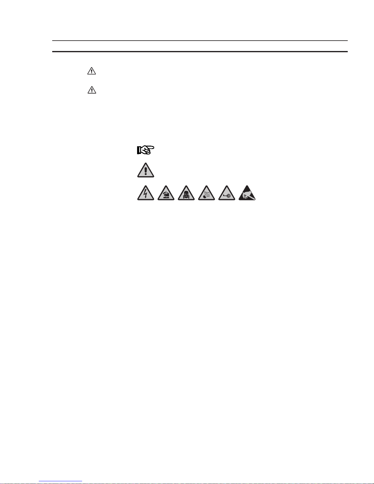
The conventions used and their meanings are presented below.
WARNING Indicates information that, if not heeded, could possibly result in loss of life or seri-
ous injury.
CAUTION Indicates information that, if not heeded, could result in relatively serious or minor
injury, damage to the product, or faulty operation.
Explanation of Symbols
This manual uses the following symbols to indicate notes and hazardous situations.
Notes for the User
General Danger
Specific Danger
Page 14

xiv
Page 15

1
SECTION 1
The Terminals of the NT-Series
This section describes the terminal hardware. This includes all the drawings, the description of the function of
the keys, the electrical connections and the dip-switch settings. It also describes how to mount the terminal.
Furthermore it describes how to handle the battery.
1.1 Front View ................................................................................. 4
1.1.1 NT4S-SF121B-E ..................................................................... 4
1.1.2 NT4S-SF122B-E ..................................................................... 5
1.1.3 NT4S-SF123B-E ..................................................................... 6
1.1.4 NT15S-SF121B-E .................................................................... 7
1.1.5 NT18S-SF121B-E .................................................................... 8
1.2 Keyboard ................................................................................... 8
1.2.1 Editing Keys......................................................................... 9
1.2.2 Control Keys ........................................................................ 10
1.2.3 Special Keys ......................................................................... 10
1.2.4 Function Keys ....................................................................... 11
1.2.4.1 Function Key Arrangement ................................................. 11
1.2.4.1.1 NT4S-SF121B-E ................................................. 11
1.2.4.1.2 NT4S-SF122B-E ................................................. 12
1.2.4.1.3 NT4S-SF123B-E ................................................. 12
1.2.4.1.4 NT15S-SF121B-E ................................................ 13
1.2.4.1.5 NT18S-SF121B-E ................................................ 13
1.2.5 Slide-in Identification Strips for the Function Keys .................................... 14
1.2.5.1 NT4S-SF121B-E ............................................................ 14
1.2.5.2 NT4S-SF122B-E ............................................................ 14
1.2.5.3 NT4S-SF123B-E ............................................................ 15
1.2.5.4 NT15S-SF121B-E ........................................................... 15
1.2.5.5 NT18S-SF121B-E ........................................................... 15
1.3 Rear View .................................................................................. 16
1.3.1 NT4S-SF121B-E ..................................................................... 16
1.3.2 NT4S-SF122B-E ..................................................................... 17
1.3.3 NT4S-SF123B-E ..................................................................... 18
1.3.4 NT15S-SF121B-E .................................................................... 19
1.3.5 NT18S-SF121B-E .................................................................... 20
1.4 Mounting the Terminals ..................................................................... 21
1.4.1 Front Panel Dimensions.............................................................. 22
1.4.1.1 NT4S-SF121B-E ............................................................ 22
1.4.1.2 NT4S-SF122B-E ............................................................ 22
1.4.1.3 NT4S-SF123B-E ............................................................ 23
1.4.1.4 NT15S-SF121B-E ........................................................... 23
1.4.1.5 NT18S-SF121B-E ........................................................... 24
1.4.2 Side View, Mounting Depth .......................................................... 24
1.4.2.1 NT4S-SF121B-E ............................................................ 24
1.4.2.2 NT4S-SF122B-E ............................................................ 25
1.4.2.3 NT4S-SF123B-E ............................................................ 26
1.4.2.4 NT15S-SF121B-E ........................................................... 27
1.4.2.5 NT18S-SF121B-E ........................................................... 28
Page 16

2
1.4.3 Panel Cutout ........................................................................ 29
1.4.3.1 NT4S-SF121B-E ............................................................ 29
1.4.3.2 NT4S-SF122B-E ............................................................ 29
1.4.3.3 NT4S-SF123B-E ............................................................ 30
1.4.3.4 NT15S-SF121B-E ........................................................... 30
1.4.3.5 NT18S-SF121B-E ........................................................... 31
1.5 Pin Assignments ............................................................................ 31
1.5.1 Pin Assignment X1 Supply Voltage ................................................... 32
1.5.2 Pin Assignment X3 SER1 TTY / 20 mA Current Loop ................................ 33
1.5.3 Pin Assignment X3 SER1 RS485 ..................................................... 34
1.5.4 Pin Assignment X3 SER1 RS232c .................................................... 35
1.5.5 Pin Assignment X3 SER2 RS232c .................................................... 35
1.5.6 Pin Assignment X4 Parallel Outputs .................................................. 36
1.6 Shield....................................................................................... 36
1.7 Display ..................................................................................... 37
1.7.1 NT4S-SF121B-E, NT4S-SF122B-E, NT4S-SF123B-E .................................. 37
1.7.2 NT15S-SF121B-E .................................................................... 37
1.7.3 NT18S-SF121B-E .................................................................... 38
1.7.4 Contrast Setting ..................................................................... 38
1.7.5 Default Contrast Setting ............................................................. 38
1.7.6 Character Attributes................................................................. 39
1.7.6.1 Font Normal................................................................ 39
1.7.6.2 Font Zoom ................................................................. 39
1.7.6.3 ASCII Character Set Table.................................................. 40
1.8 User-Mode Switch .......................................................................... 41
1.9 Battery ..................................................................................... 42
1.10 Fuse ........................................................................................ 43
1.11 Application Memory ........................................................................ 43
Page 17

3
The Terminals of the NT-Series Section 1
1 The Terminals of the NT-Series
This manual is only valid for the following operating terminals:
- NT4S-SF121B-E
- NT4S-SF122B-E
- NT4S-SF123B-E
- NT15S-SF121B-E
- NT18S-SF121B-E
The terminals of the NT-series are the favourite Man-Machine-Interfaces for all
applications, where an optimum relation of size to function is needed.
All terminals of the NT-series permit sealed installation in accordance with the IP65
degree of protection.
Each terminal is equipped with function keys, that can be individually labelled with
slide-in strips.
A built-in lithium battery buffers the data in the RAM and also supplies the real time
clock with power.
The discharge state of the battery is monitored constantly by the system.
The communication with a controller and logging printer is supported by a universal
interface, unique for all terminals of the NT-series.
The operator guidance is done by means of a comfortable programming software.
Page 18

4
The Terminals of the NT-Series Section 1-1
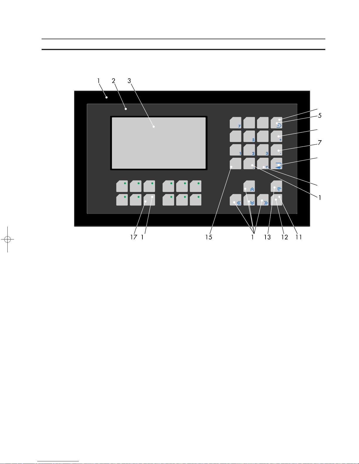
1.1 Front View
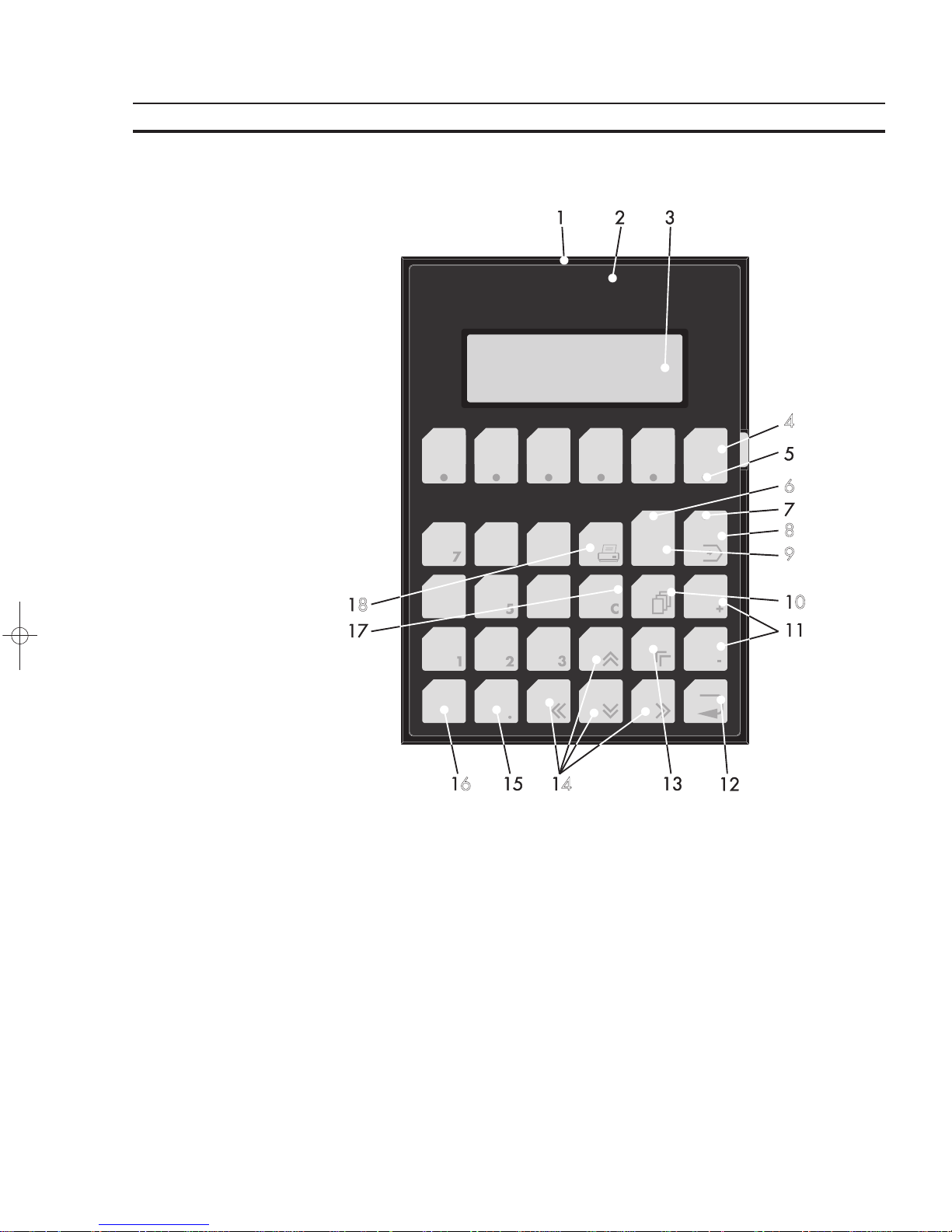
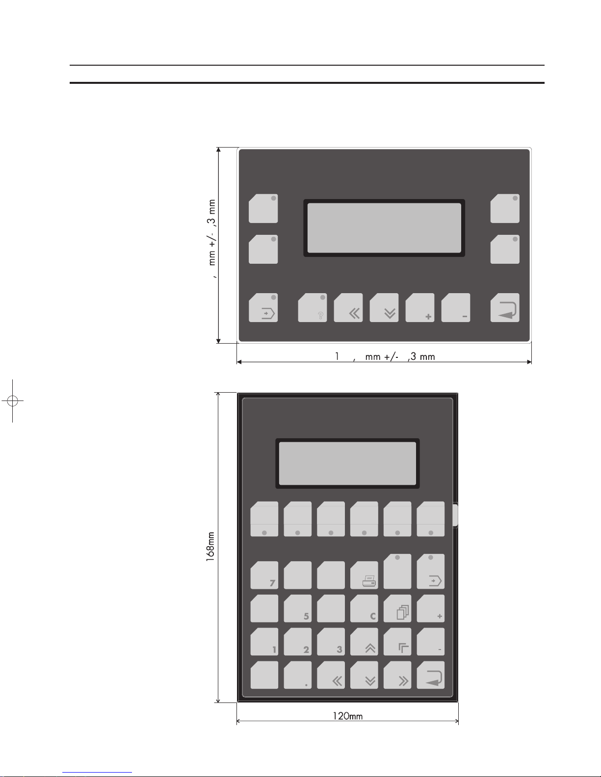
1.1.1 NT4S-SF121B-E
1 Front Panel
2 Front Cover
3 Display
4 Status-LED Function Key (F3)
5 Function Key (F3)
6 Status-LED Function Key (F4)
7 Function Key (F4)
8 Key Enter
9 Key Minus
10 Key Plus
11 Key Cursor Down
12 Key Cursor Left
13 Status-LED Key Help
14 Key Help
15 Status-LED Key Data Release
16 Key Data Release
17 Function Key (F2)
18 Status-LED Function Key (F2)
19 Function Key (F1)
20 Status-LED Function Key (F1)
Page 19
5
The Terminals of the NT-Series Section 1-1
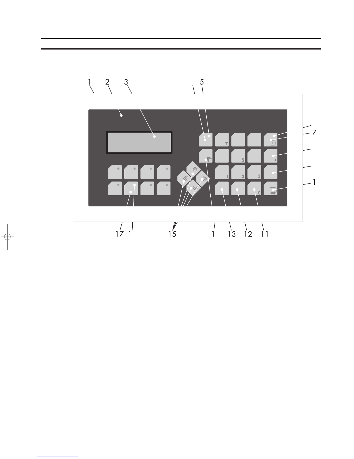
1.1.2 NT4S-SF122B-E
1 Front Panel
2 Front Cover
3 Display
4 Function Key (F6)
5 Status-LED Function Key (F6)
6 Status-LED Key Help
7 Status-LED Key Data Release
8 Key Data Release
9 Key Help
10 Key Scroll
11 Key Plus, Minus
12 Key Enter
13 Key Cursor Home
14 Key Cursor Right, Left, Up, Down
15 Key Dot
16 Keys 0 to 9
17 Key Clear
18 Key Print
Page 20
6
The Terminals of the NT-Series Section 1-1
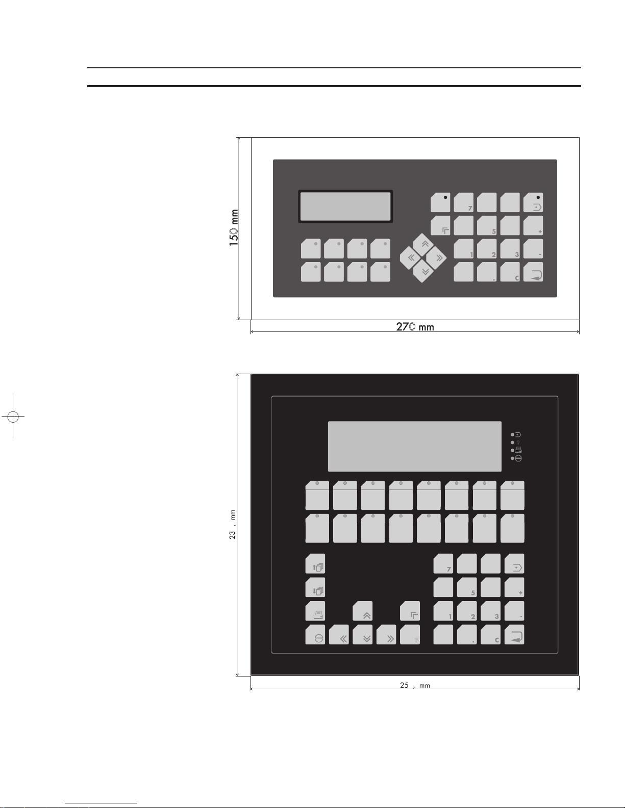
1.1.3 NT4S-SF123B-E
1 Front Panel
2 Front Cover
3 Display
4 Key Help
5 Status-LED Key Help
6 Status-LED Key Data Release
7 Key Data Release
8 Key Plus
9 Key Minus
10 Key Enter
11 Key Clear
12 Key Dot
13 Keys 0 to 9
14 Key Cursor Home
15 Key Cursor Right, Left, Up, Down
16 Status-LED Function Key (F6)
17 Function Key (F6)
Page 21
7
The Terminals of the NT-Series Section 1-1
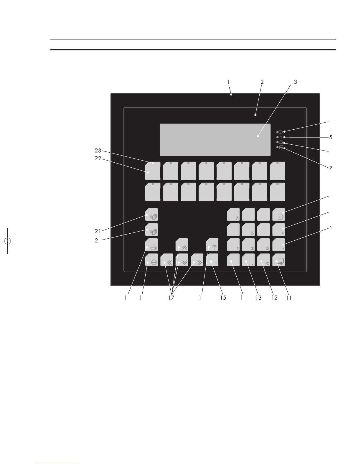
1.1.4 NT15S-SF121B-E
1 Front Panel
2 Front Cover
3 Display
4 Status-LED Data Release
5 Status-LED Help
6 Status-LED Print
7 Status-LED Acknowledge
8 Key Data Release
9 Key Plus
10 Key Minus
11 Key Enter
12 Key Clear
13 Key Dot
14 Keys 0 to 9
15 Key Help
16 Key Cursor Home
17 Key Cursor Right, Left, Up, Down
18 Key Acknowledge
19 Key Print
20 Key Page Down
21 Key Page Up
22 Function Key (F1)
23 Status-LED Function Key (F1)
Page 22
8
The Terminals of the NT-Series Section 1-1
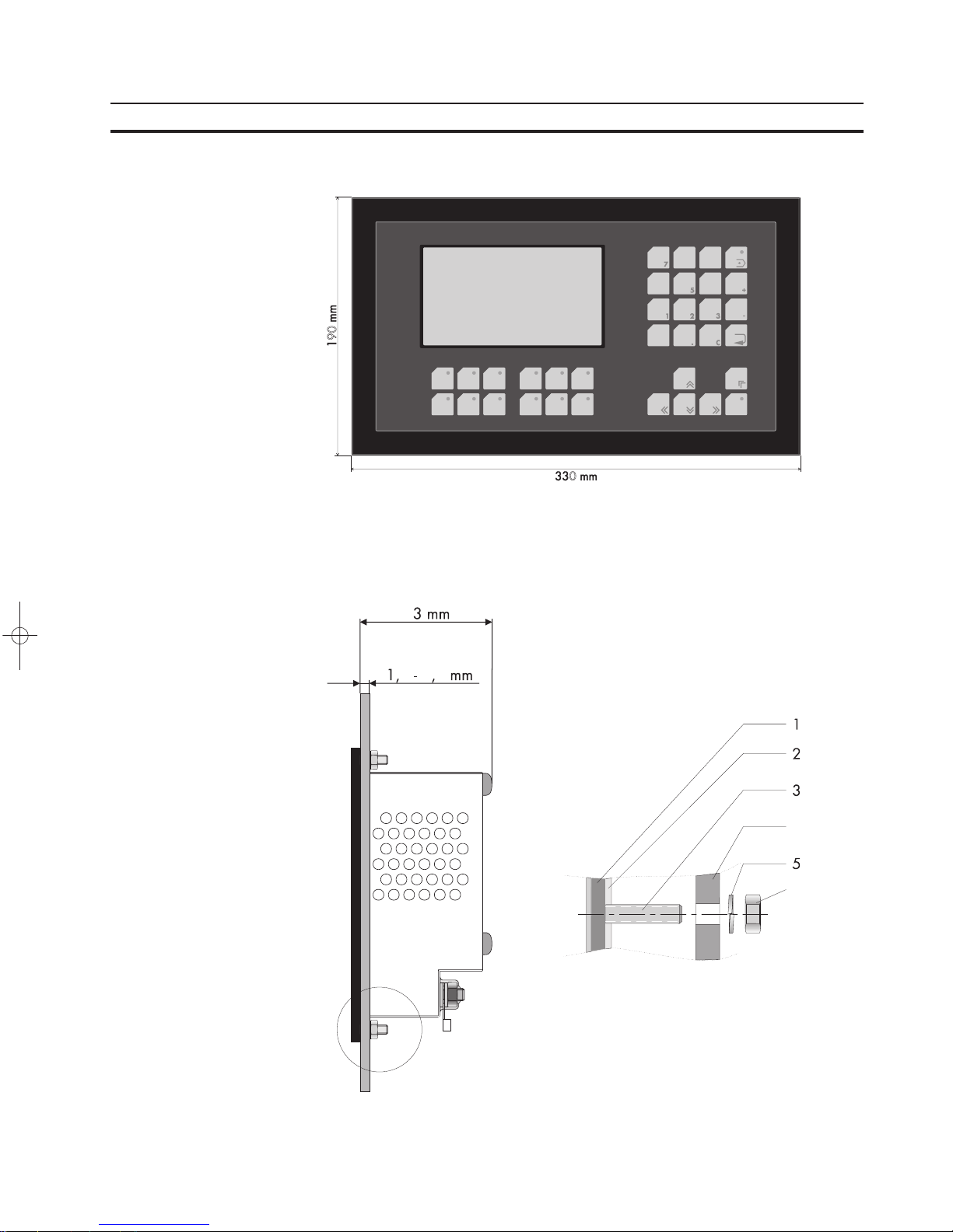
1.1.5 NT18S-SF121B-E
1 Front Panel
2 Front Cover
3 Display
4 Status-LED Key Data Release
5 Key Data Release
6 Key Plus
7 Key Minus
8 Key Enter
9 Key Clear
10 Key Dot
11 Status-LED Key Help
12 Key Help
13 Key Cursor Home
14 Key Cursor Right, Left, Up, Down
15 Keys 0 to 9
16 Status-LED Function Key (F6)
17 Function Key (F6)
1.2 Keyboard
The terminals NT4S-SF121B-E, NT4S-SF123B-E and NT18S-SF121B-E are
equipped with a keyboard made of short-stroke keys. The stroke length is approximately 0.5 mm.
The terminals NT4S-SF122B-E and NT15S-SF121B-E are equipped with a keyboard made of membrane keys. The stroke length is approximately 0.3 mm.
The key area of each key is 16 × 16 mm. The keys are covered by an embossed
polyester sheet which is resistant to environmental effects. These combinations
allows a sensitive use of the keys.
The status-LEDs of the function keys illuminate green. In transparent mode the
keys supply a fixed start and stop code. In standard mode, the function of the keys
is as defined in the application.
Page 23

9
The Terminals of the NT-Series Section 1-2
1.2.1 Editing Keys
Key: 0 and ( ) ˚is used to edit data within the editor. If the system variable Shift or
ShiftCase is programmed, the characters ( and ) and ˚can be entered.
Key: 1 and STU is used to edit data within the editor. If the system variableShift or
ShiftCase is programmed, the characters S and T and U can be entered.
Key: 2 and VWX is used to edit data within the editor. If the system variableShift or
ShiftCase is programmed, the characters V and W and X can be entered.
Key: 3 and YZ% is used to edit data within the editor. If the system variableShift or
ShiftCase is programmed, the characters Y and Z and % can be entered.
Key: 4 and JKL is used to edit data within the editor. If the system variableShift or
ShiftCase is programmed, the characters J and K and L can be entered.
Key: 5 and MNO is used to edit data within the editor. If the system variableShift or
ShiftCase is programmed, the characters M and N and O can be entered.
Key: 6 and PQR is used to edit data within the editor. If the system variableShift or
ShiftCase is programmed, the characters P and Q and R can be entered.
Key: 7 and ABC is used to edit data within the editor. If the system variableShift or
ShiftCase is programmed, the characters A and B and C can be entered.
Key: 8 and DEF is used to edit data within the editor. If the system variableShift or
ShiftCase is programmed, the characters D and E and F can be entered.
Key: 9 and GHI is used to edit data within the editor. If the system variableShift or
ShiftCase is programmed, the characters G and H and I can be entered.
Key: Decimal Point and :?! is used to edit data within the editor. If the system
variable Shift or ShiftCase is programmed, the characters : and ? and ! can be
entered.
Key: Minus and \*/ can be used to enter negative values within the editor. In the
increment editor, the variable value is decremented by 1. When the key is held
down, the function is repeated at a rate of repetition that is automatically increased.
If the system variable Shift or ShiftCase is programmed, the characters \ and
* and / can be entered.
Page 24

10
The Terminals of the NT-Series Section 1-2
Key: Plus and ,=. can be used to enter positive values within the editor. In the
increment editor, the variable value is incremented by 1. When the key is held
down, the function is repeated at a rate of repetition that is automatically increased.
If the system variableShift orShiftCase is programmed, the characters , and =
and . can be entered.
1.2.2 Control Keys
Key: Cursor left can be programmed to directly select I/O masks.
In the editor, it moves the cursor to the left.
Key: Cursor right can be programmed to directly select I/O masks.
In the editor, it moves the cursor to the right.
Key: Cursor up can be programmed to directly select I/O masks.
In the editor, it moves the cursor upwards.
Key: Cursor down can be programmed to directly select I/O masks.
In the editor, it moves the cursor downwards.
Key: Cursor home can be programmed to directly select I/O masks.
In the editor, it moves the cursor to the position of the first input variable.
Key: Page down is used to page through tables, recipes and messages. The func-
tionality corresponds to the system variable ‘TabPgDn’. The key allows data contents towards the bottom of the table to be viewed.
Key: Page upis used to page through tables, recipes and messages. The function-
ality corresponds to the system variable ‘TabPgUp’. The key allows data contents
towards the top of the table to be viewed.
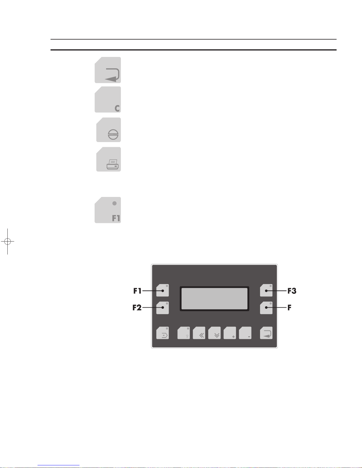
1.2.3 Special Keys
Key: Help keyalways displays the current help text (online help). When the status-
LED help flashes, it signals that an error message is pending. The error or system
message is always displayed in plain-text.
Key: Data Release key is used to switch from a menu into the editor. The status-
LED data release lights up when the editing mode is active. When the Data Release key is pressed within the editor, the editing mode is exited.
Page 25
11
The Terminals of the NT-Series Section 1-2
Key: Enteris used to conclude data entry. When pressed while in the startup mask,
the key switches into the setup mask.
Key: Clear deletes the character beneath the cursor when it is used in an editor.
Deletes the selected messages from the data memory.
Key: Acknowledge is used as an acknowledge key for the message system.
Key: Print can be used as a soft key to activate various print processes.
1.2.4 Function Keys
Keys: Function Keys F1 to F16 with status-LEDs for functional feedback. In stan-
dard mode, the key functions can be freely assigned to a soft key functionality;
either as direct keys for menu control or to activate a function in the controller.
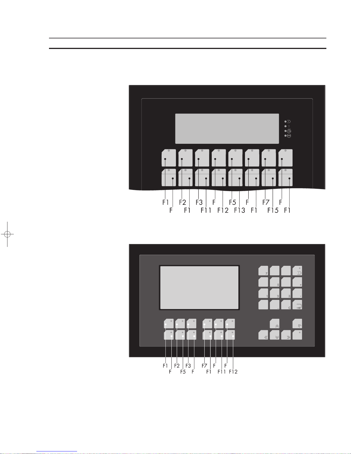
1.2.4.1 Function Key Arrangement
1.2.4.1.1 NT4S-SF121B-E
Page 26

12
The Terminals of the NT-Series Section 1-2
1.2.4.1.2 NT4S-SF122B-E
1.2.4.1.3 NT4S-SF123B-E
Page 27
13
The Terminals of the NT-Series Section 1-2
1.2.4.1.4 NT15S-SF121B-E
1.2.4.1.5 NT18S-SF121B-E
Page 28
14
The Terminals of the NT-Series Section 1-2
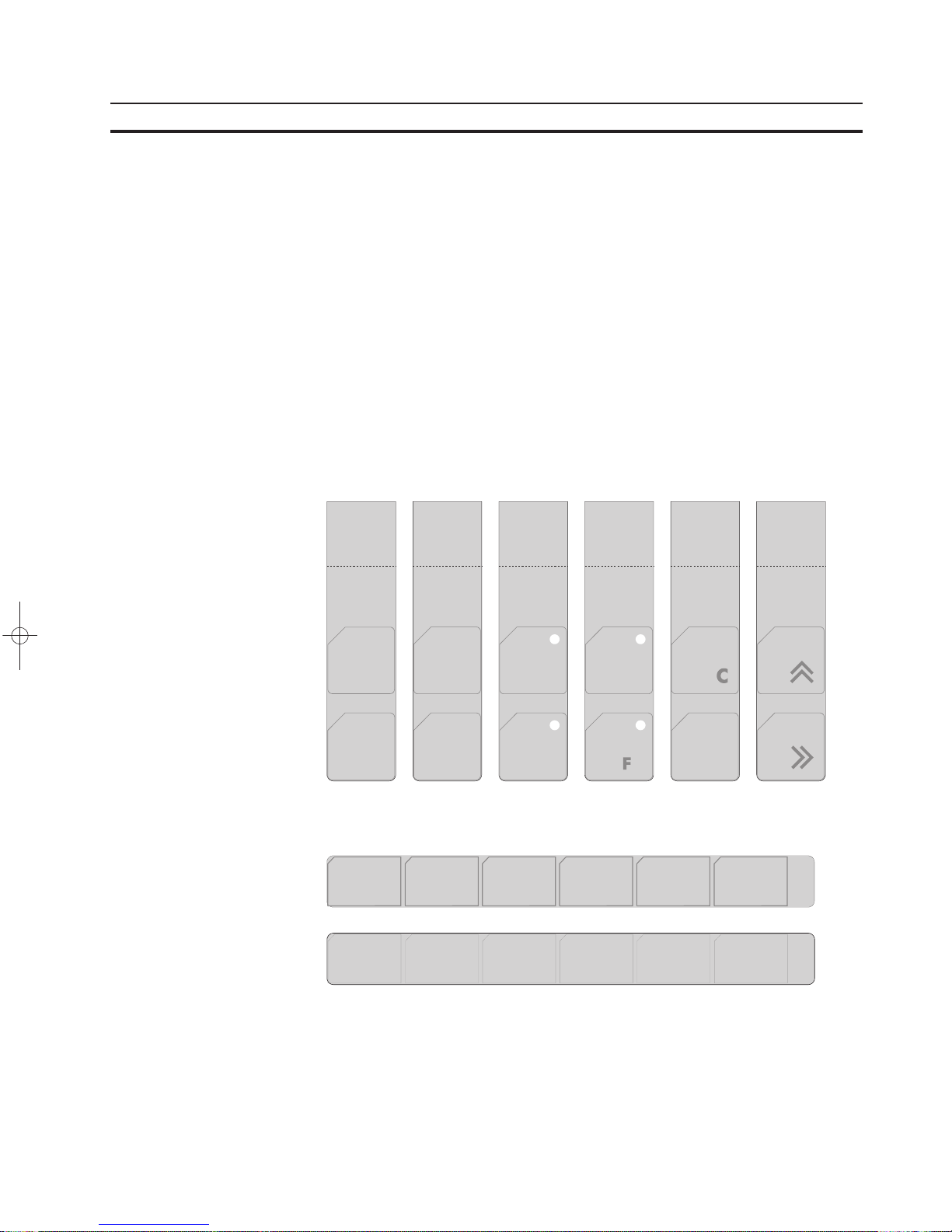
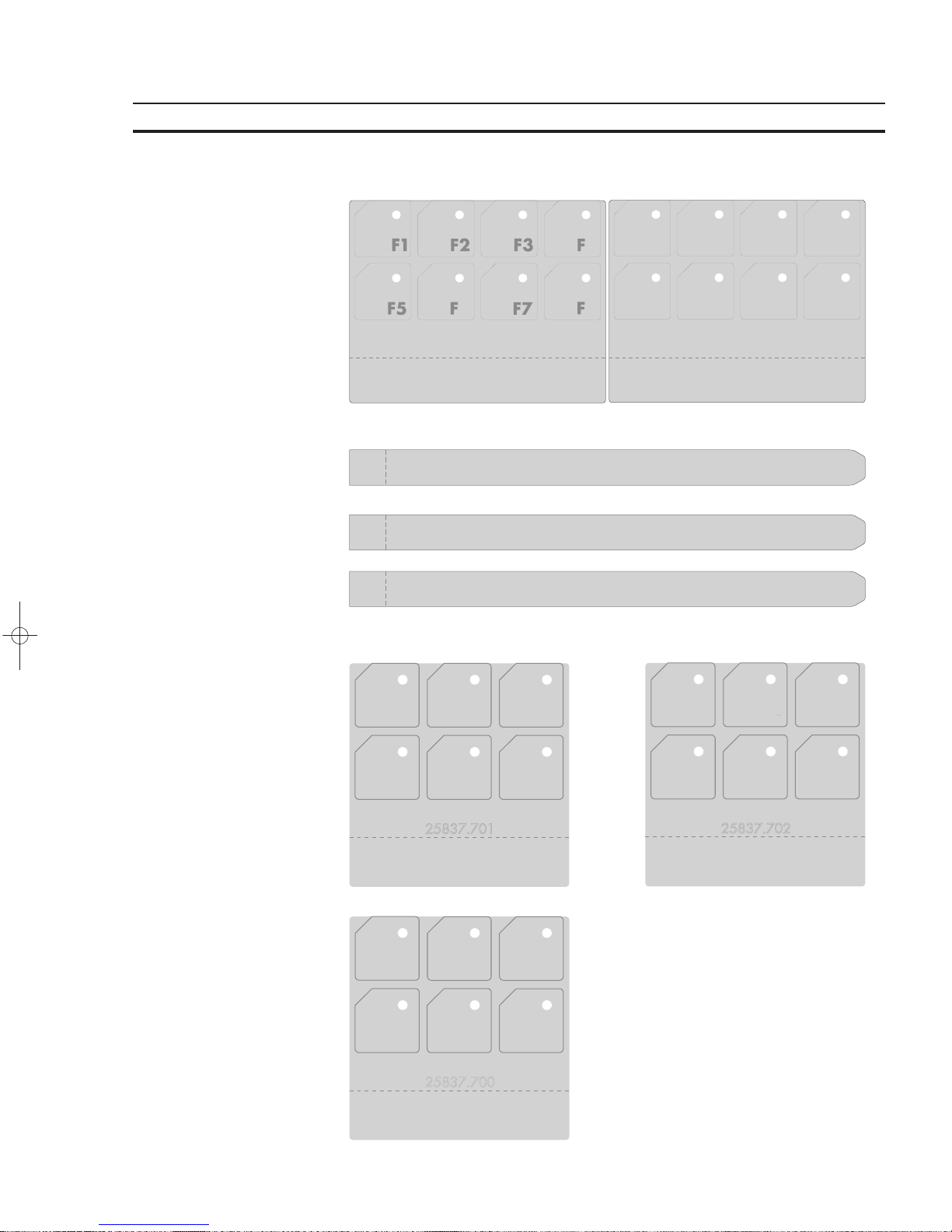
1.2.5 Slide-in Identification Strips for the Function Keys
The terminals are equipped with a set of slide-in identification strips.
Each set consists of ready-to-use labelled and blank slide-in identification strips.
Various labeling methods are recommended, depending on the number of terminals involved.
Suitable labeling methods for:
single terminal: labeling with an indelible pen
small number of terminals: transparency with laser printing
large number of terminals: identification strips printed according to customer’s
needs
1.2.5.1 NT4S-SF121B-E
1.2.5.2 NT4S-SF122B-E
Page 29
15
The Terminals of the NT-Series Section 1-2
1.2.5.3 NT4S-SF123B-E
1.2.5.4 NT15S-SF121B-E
1.2.5.5 NT18S-SF121B-E
Page 30
16
The Terminals of the NT-Series Section 1-3
1.3 Rear View
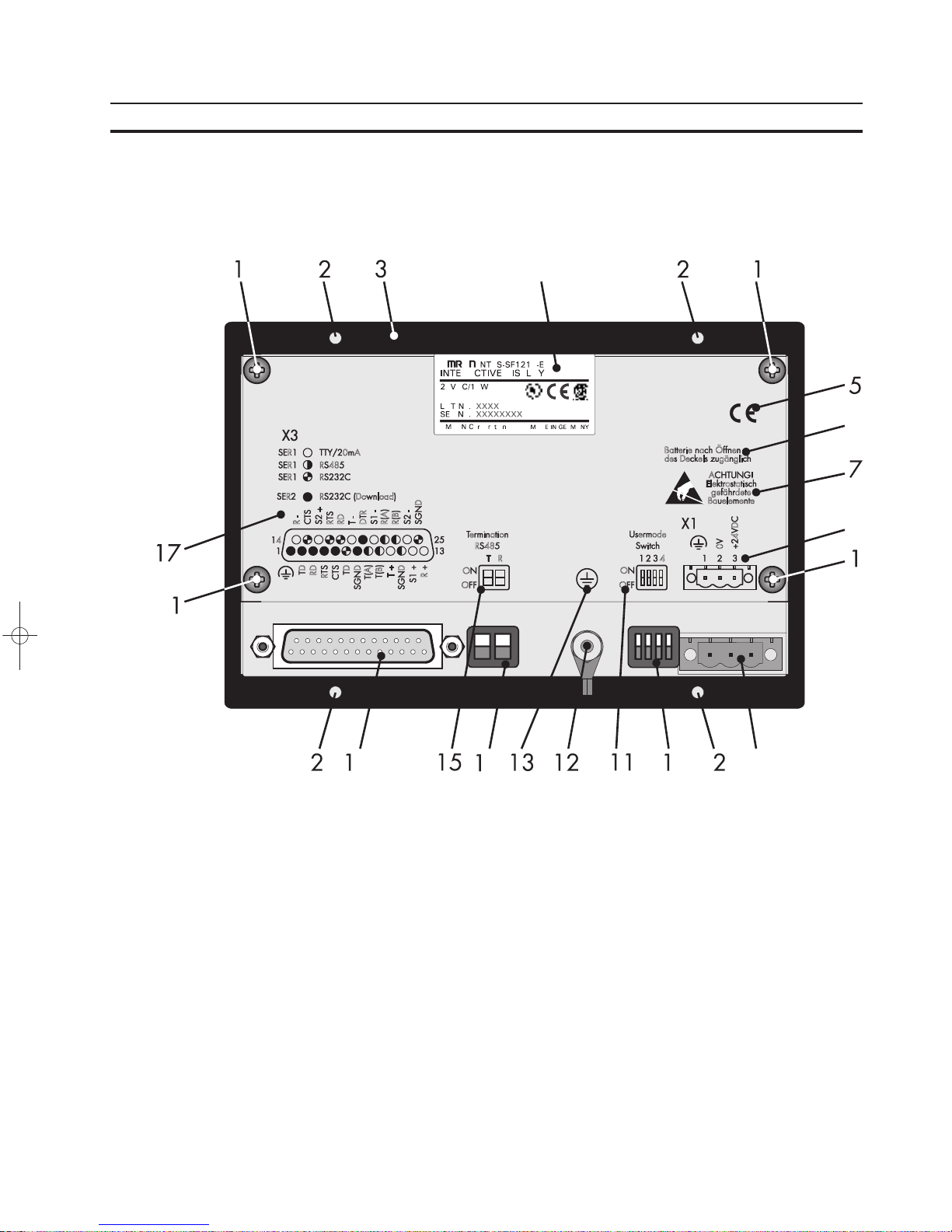
1.3.1 NT4S-SF121B-E
1 Fastening Screw for Enclosure
2 Mounting Bolts
3 Front Panel
4 Name Plate
5 CE-Sign
6 Note for Battery
7 Warning Note
8 Pin Assignment Connector X1
9 Connector X1 (Power Supply)
10 User-Mode Switch
11 Switch Assignment User-Mode Switch
12 Ground Screw
13 Sign for Ground Srew
14 Terminator Switch (RS485)
15 Switch Assignment Terminator Switch
16 Female Connector X2
17 Pin Assignment Female Connector X2
Page 31
17
The Terminals of the NT-Series Section 1-3
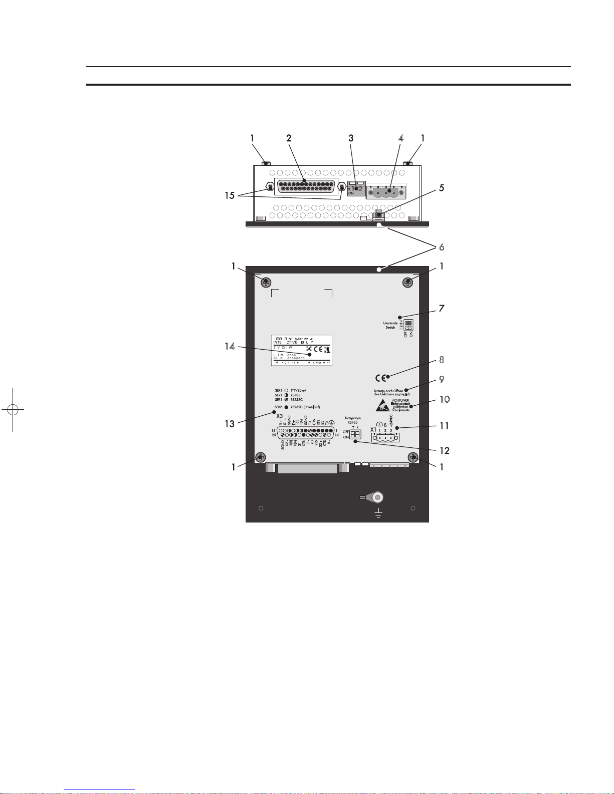
1.3.2 NT4S-SF122B-E
1 Fastening Screw for Enclosure
2 Female Connector X3
3 Terminator Switch (RS485)
4 Connector X1 (Power Supply)
5 Ground Screw
6 Front Panel
7 Switch Assignment User-Mode
Switch
8 CE-Sign
9 Note for Battery
10 Warning Note
11 Pin Assignment Connector X1
12 Switch Assignment Terminator
Switch
13 Pin Assignment Female Connec-
tor X3
14 Name Plate
15 Fastening Screw for Female
Connector X3
Page 32

18
The Terminals of the NT-Series Section 1-3
1.3.3 NT4S-SF123B-E
1 Mounting Bolts
2 Fastening Screw for Enclosure
3 Front Panel
4 Rubber Sealing
5 Name Plate
6 Switch Assignment User-Mode Switch
7 User-Mode Switch
8 Switch Assignment Terminator Switch
9 Terminator Switch (RS485)
10 Pin Assignment Female Connector X3
11 Female Connector X3
12 Fastening Screw for Female Connector X3
13 Pin Assignment Connector X1
14 Connector X1 (Power Supply)
15 Ground Screw
16 Warning Note
17 CE-Sign
18 Note for Battery
Page 33
19
The Terminals of the NT-Series Section 1-3
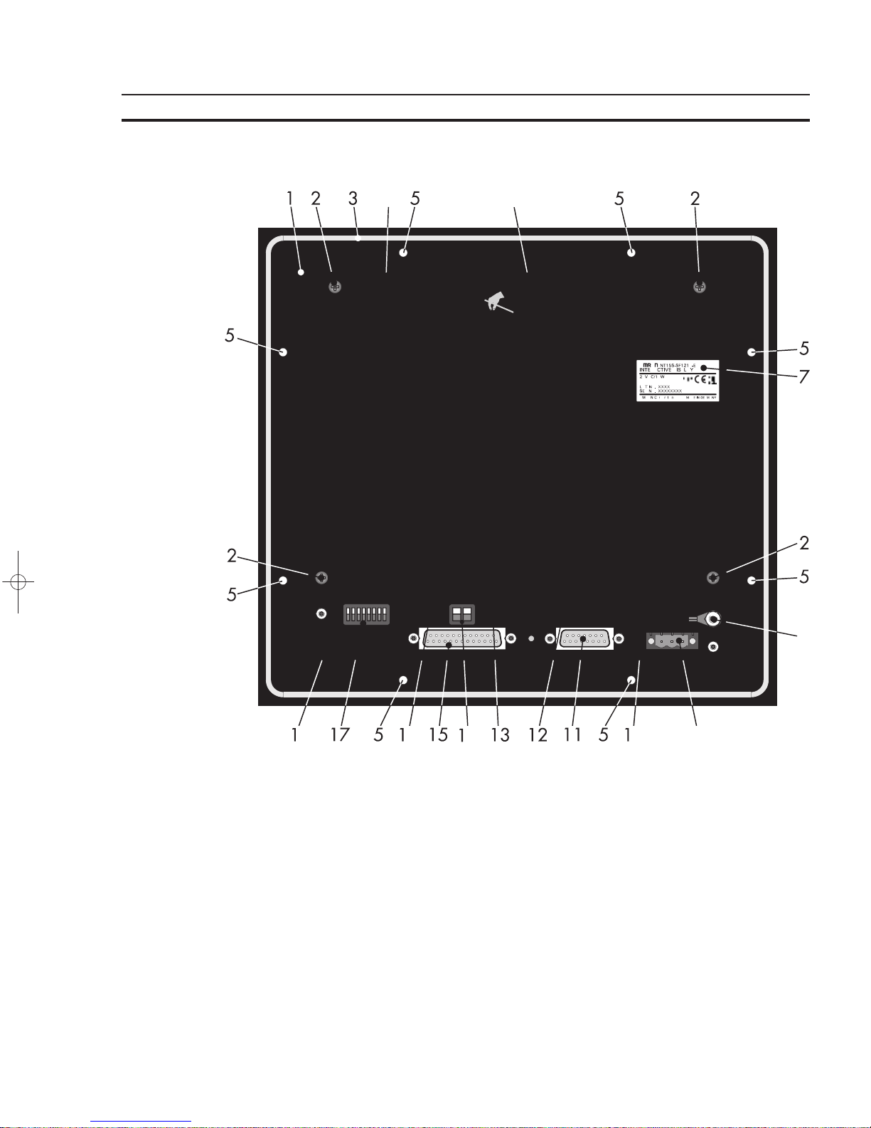
1.3.4 NT15S-SF121B-E
1 Front Panel
2 Fastening Screw for Enclosure
3 Rubber Sealing
4 Warning Note
5 Mounting Bolts
6 Note for Battery
7 Name Plate
8 Ground Screw
9 Connector X1 (Power Supply)
10 Pin Assignment Connector X1
11 Connector X4 (Parallel Outputs)
12 Pin Assignment Connector X4 (Parallel Outputs)
13 Switch Assignment Terminator Switch
14 Terminator Switch (RS485)
15 Female Connector X3
16 Pin Assignment Female Connector X3
17 User-Mode Switch
18 Switch Assignment User-Mode Switch
Page 34

20
The Terminals of the NT-Series Section 1-3
1.3.5 NT18S-SF121B-E
1 Mounting Bolts
2 Fastening Screw for Enclosure
3 Front Panel
4 Rubber Sealing
5 Warning Note
6 Name Plate
7 Note for Battery
8 Warning Note
9 Switch Assignment Terminator Switch
10 Terminator Switch (RS485)
11 Pin Assignment Female Connector X3
12 Fastening Screw for Female Connector X3
13 Female Connector X3
14 Switch Assignment User-Mode Switch
15 User-Mode Switch
16 Pin Assignment Connector X1
17 Connector X1 (Power Supply)
18 Ground Screw
Page 35

21
The Terminals of the NT-Series Section 1-4
1.4 Mounting the Terminals
The terminals with mounting bolts or lateral mounting slits are mounted from the
rear side. The rear panel mounting is suitable for easy and sealed installation places where the rear side of the unit is accessible.
The terminal NT15S-SF121B-E is mounted from the front side. This type of installation is suitable for easy and sealed installation where the rear side of the unit is
not accessible.
The terminals are particularly suitable for mounting in control cabinets with a
mounting plate thickness of approximately 1 to 10 mm.
The front panels permit sealed installation of the units in accordance with the IP65
degree of protection.
The terminals
- NT4S-SF123B-E
- NT18S-SF121B-E
- NT15S-SF121B-E
have a circumferential groove milled into the rear side of the front plate, containing
a rubber sealing.
The terminals
- NT4S-SF121B-E
- NT4S-SF122B-E
are equipped with a foam sealing on the rear side of the front plate.
All parts for mounting the units are supplied with the spare parts set.
Special care needs to be taken during installation to maintain this high degree of
protection. The appliance is inserted from the front through the mounting panel
cutout and fastened with the fasteners of the spare parts set. The sealing must be
positioned evenly and the fastening elements tightened uniformly.
When installing the terminal, keep a minimum space of 30 mm around the terminal
for adequate air circulation.
The tightness between the front panel and the mounting surface depends on
the care during installation.
Mounting and connection of the operating terminal to the power supply must be
carried out by authorized and qualified personnel with EMC training.
Operating terminals must be grounded according to regulations.
The application-specific safety- and accident prevention regulations must be observed during the mounting and connection to the power supply, e.g.:
- EN 60204, Electrical Equipment of Machines
- EN 292, Safety of Machinery, General Principles for Design
- DIN 57 100 Part 410, Protection against Electric Shock
Hazardous voltages can exist inside electrical installations that can pose a danger
to humans. Coming in contact with live parts may result in electric shock!
Page 36
22
The Terminals of the NT-Series Section 1-4
1.4.1 Front Panel Dimensions
1.4.1.1 NT4S-SF121B-E
1.4.1.2 NT4S-SF122B-E
Page 37
23
The Terminals of the NT-Series Section 1-4
1.4.1.3 NT4S-SF123B-E
1.4.1.4 NT15S-SF121B-E
Page 38
24
The Terminals of the NT-Series Section 1-4
1.4.1.5 NT18S-SF121B-E
1.4.2 Side View, Mounting Depth
1.4.2.1 NT4S-SF121B-E
1 Front Panel
2 Foam Sealing
3 Press-In Threaded Bolt M3 x 9
4 Mounting Surface Thickness 1 to 6 mm
5 Spring Lock Washer B3 DIN127 Form B
6 Nut M3 DIN934
Page 39

25
The Terminals of the NT-Series Section 1-4
1.4.2.2 NT4S-SF122B-E
1 Front Panel
2 Foam Sealing
3 Monting Surface Thickness 1 to
14 mm
4 Threaded Pin DIN 914 M4 x 35
5 Mounting Bracket
Page 40

26
The Terminals of the NT-Series Section 1-4
1.4.2.3 NT4S-SF123B-E
1 Front Panel
2 Circumferential Rubber Sealing
3 Press-In Threaded Bolt M4 x 16
4 Mounting Surface Thickness 1 to 10 mm
5 Spring Lock Washer B4
DIN127 Form B
6 Nut M4 DIN934
Page 41

27
The Terminals of the NT-Series Section 1-4
1.4.2.4 NT15S-SF121B-E
1 Front Panel
2 Circumferential Rubber Sealing
3 Press-In Threaded Bolt M4 x 16
4 Mounting Surface Thickness 1 to
10 mm
5 Spring Lock Washer B4 DIN127
Form B
6 Nut M4 DIN934
Page 42

28
The Terminals of the NT-Series Section 1-4
1.4.2.5 NT18S-SF121B-E
1 Front Panel
2 Circumferential Rubber Sealing
3 Press-In Threaded Bolt M4 x 16
4 Mounting Surface Thickness 1 to
10 mm
5 Spring Lock Washer B4 DIN127
Form B
6 Nut M4 DIN934
Page 43

29
The Terminals of the NT-Series Section 1-4
1.4.3 Panel Cutout
1.4.3.1 NT4S-SF121B-E
1 4 Holes with a Diameter of 3.5 mm
1.4.3.2 NT4S-SF122B-E
Page 44

30
The Terminals of the NT-Series Section 1-4
1.4.3.3 NT4S-SF123B-E
1 6 Holes with a Diameter of 4.5 mm
1.4.3.4 NT15S-SF121B-E
1 8 Holes with a Diameter of 4.5 mm
Page 45
31
The Terminals of the NT-Series Section 1-5
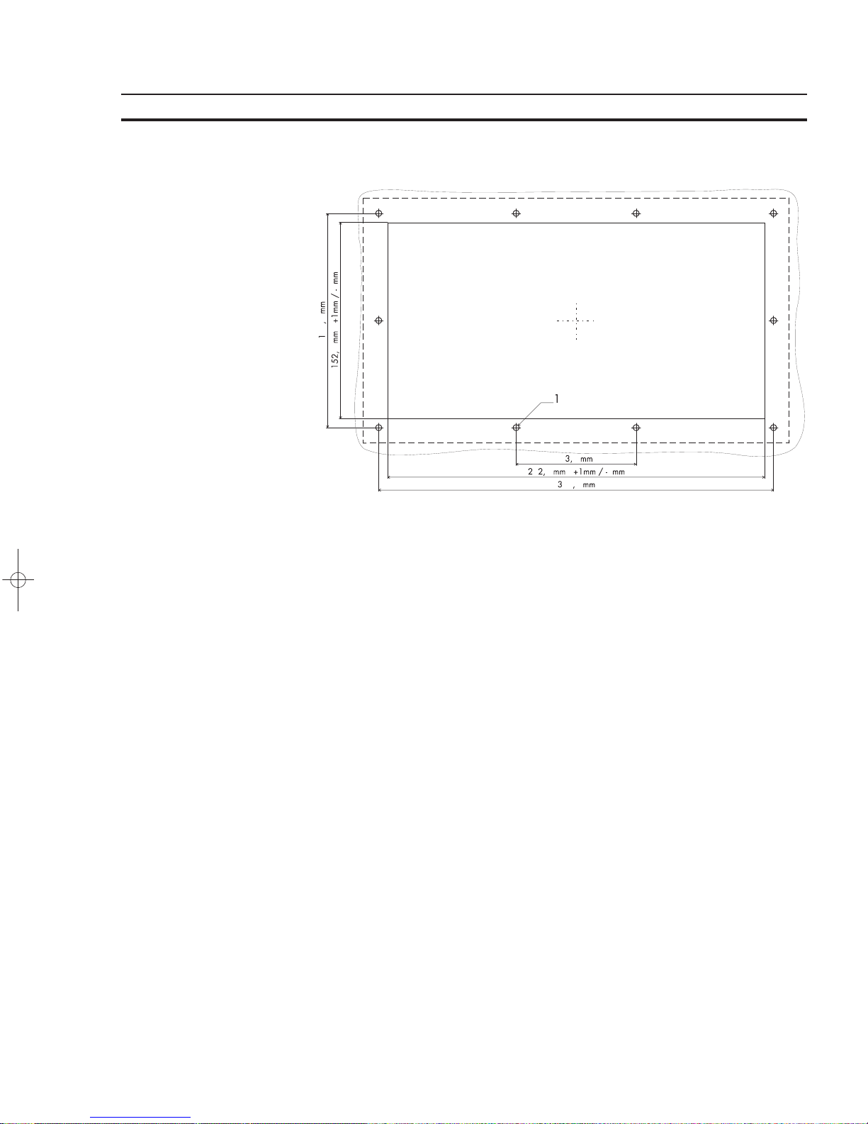
1.4.3.5 NT18S-SF121B-E
1 10 Holes with a Diameter of 4.5 mm
1.5 Pin Assignments
The operating terminals are equipped with a universal interface by default. This
universal interface combines several interface standards within one physical connector. The connector is divided into two channels. The channel for communication
(SER1) is divided from the channel for download/upload/printer (SER2). The channels can operate independent of each other.
The channel for communication (SER1) can handle - specified by protocol - only
one of the three interface standards.
Connector X1 .........24 VDC ...........Supply Voltage
Connector X3 SER1 . ..TTY / 20 mA ......Communication
Connector X3 SER1 . ..RS485 ............Communication
Connector X3 SER1 . ..RS232c ...........Communication
Connector X3 SER2 . ..RS232c ...........Download/Upload/Logging Printer
The operating terminal NT15S-SF121B-E has additional parallel outputs:
Connector X4 .........Parallel Outputs
The parallel outputs are suitable for access of PLC-inputs.
Page 46

32
The Terminals of the NT-Series Section 1-5
1.5.1 Pin Assignment X1 Supply Voltage
The supply voltage is connected via the connector X1.
Connector in the terminal: 3-pin male connector strip Phoenix COMBICON
MSTBV 2,5/3-GF
Pin Designation Function
1
Signal Ground
2 0 V Supply Voltage 0 V
3 24 VDC Supply Voltage 24 VDC
The supply voltage is connected via a plug-in 3-pin female connector strip. The
cable is secured in the female connector strip by means of screw terminals. Cables
with fine wires with a cross-section of up to 2.5mm
2
can be used. The female connector strip is secured in position by means of a screw-type locking.
The female connector strip of the type Phoenix COMBICON MSTB 2.5/3-STF is
supplied.
Hazardous voltages can exist inside electrical installations that can pose a danger
to humans. Coming in contact with live parts may result in electric shock!
Please note with respect to pin assignment:
If shielded connecting cables are used for the supply voltage, the shield should be
connected to the ground screw.
Any protective conductors in the cable must be connected with pin 1.
Separate ground screw for protective grounding
A separate ground conductor must be provided for the ground screw in each case.
The minimum cross-section of the ground conductor must be 1.5 mm
2
. Compliance
with this information increases the operational safety.
Page 47

33
The Terminals of the NT-Series Section 1-5
1.5.2 Pin Assignment X3 SER1 TTY / 20 mA Current Loop
TTY / 20 mA current loop, passive
Pin Designation Channel Function
10 T+ SER1 Transmit Data, Positive Polarity
13 R+ SER1 Receive Data, Positive Polarity
14 R- SER1 Receive Data, Negative Polarity
19 T- SER1 Transmit Data, Negative Polarity
TTY / 20 mA current loop, active
Pin Designation Channel Function
10 T+ SER1 Transmit Data, Positive Polarity
12 S1+ SER1 Power Source 2, Positive Polarity
13 R+ SER1 Receive Data, Positive Polarity
14 R- SER1 Receive Data, Negative Polarity
16 S2+ SER1 Power Source 1, Positive Polarity
19 T- SER1 Transmit Data, Negative Polarity
21 S1- SER1 Power Sink 1, Negative Polarity
24 S2- SER1 Power Sink 2, Negative Polarity
Termination:
When using the channel SER1 as current loop the terminator switches for RS485
must be
switched OFF!
The interface can be connected as either an active or passive current loop depending on the wiring. The transmit line and the receive line are provided with separate
20mA power sources. The compliance voltage is approximately 24 VDC.
The maximum baud rate is 19200Bd. The maximum cable length depends on the
baud rate and rate of transmission errors.
For longer cable lengths, the 20mA power supply should be fed by the transmitting
unit. This can decrease crosstalk on the signal lines considerably.
In idle state (signal logical 1) a current loop of 20 mA can be measured on the cable.
Signal logical 1 - Current flow 20mA
Signal logical 0 - Current flow is interrupted
A shielded cable with twisted pair wires (cable type LiYCY-TP) and a minimum
cross section of 0.08 mm
2
must be used. The maximum cable length is 100 m.
Connect the cable shield to the metal hoods of the connectors over as large a
surface as possible!
Page 48

34
The Terminals of the NT-Series Section 1-5
1.5.3 Pin Assignment X3 SER1 RS485
The interface RS485 is suitable for point-to-point connections and multipoint connections.
Termination for point-to-point connection:
For operation with point-to-point connection the termination must
always be acti-
vated.
Termination for multipoint connection:
For operation with multipoint connections only the termination at the cable end
must be activated.
The signals of the interface are electrically isolated.
The configuration of the hardware can be adapted to different systems. The associated wires are marked with ‘A’ and ‘B’. Some descriptions refer to the pins with ‘+’
and ‘-’, where the following applies: A = + and B = -. The voltage levels comply with
the standards and are defined as follows:
Signal logical 1 - U
A
- UB,= -0.3 V i.e. (UA, UB)
Signal logical 0 - U
A
- UB.= +0.3 V i.e. (UA. UB)
Pin Designation Channel Function
8 T(A) SER1 Transmit Data Channel A
9 T(B) SER1 Transmit Data Channel B
11 SGND SER1 Signal Ground
22 RD(A) SER1 Receive Data Channel A
23 RD(B) SER1 Receive Data Channel B
A shielded cable with twisted pair wires (cable type LiYCY-TP) and a minimum
cross section of 0.34 mm
2
(for 400 m) must be used. The maximum cable length is
400 m.
Connect the cable shield to the metal hoods of the connectors over as large a
surface as possible!
Page 49

35
The Terminals of the NT-Series Section 1-5
1.5.4 Pin Assignment X3 SER1 RS232c
Interface for communication with controller.
Pin Designation Channel Function
1 Shield SER1 Shield
6 TD SER1 Transmit Data
15 CTS SER1 Clear To Send
17 RTS SER1 Request To Send
18 RD SER1 Receive Data
25 SGND SER1 Signal Ground
A shielded cable with stranding in layers (cable type LiYCY) and with a minimum
cross-section of 0.25 mm
2
must be used. The maximum cable length is 15 m.
Connect the cable shield to the metal hoods of the connectors over as large a
surface as possible!
1.5.5 Pin Assignment X3 SER2 RS232c
Interface for download, upload and logging printer.
Pin Designation Channel Function
2 TD SER2 Transmit Data
3 RD SER2 Receive Data
4 RTS SER2 Request to Send
5 CTS SER2 Clear To Send
7 SGND SER2 Signal Ground
20 DTR SER2 Data Terminal Ready
A shielded cable with stranding in layers (cable type LiYCY) and with a minimum
cross-section of 0.25 mm
2
must be used. The maximum cable length is 15 m.
Connect the cable shield to the metal hoods of the connectors over as large a
surface as possible!
Page 50

36
The Terminals of the NT-Series Section 1-5
1.5.6 Pin Assignment X4 Parallel Outputs
Open-collector-outputs, which switch the positive potential, are used as parallel
outputs. These outputs are suitable for direct control of PLC inputs. The outputs
can be activated by means of function keys or the controller. The assignment of
these functions is carried out in the programming software. The parallel outputs are
designed for use in standard mode only.
Technical Data:
Input voltage 24VDC in accordance with EN61131-2
Output Current max. 0.2 A
The outputs are short-circuit-proof!
The voltage supply must be provided externally. Pins 9 through 13 for the negative
potential are connected internally.
Connector in the operating terminal: 15-pin SubminD male connector strip
Pin Designation Function
1 A1 Output 1
2 A2 Output 2
3 A3 Output 3
4 A4 Output 4
5 A5 Output 5
6 A6 Output 6
7 A7 Output 7
8 A8 Output 8
9 0V Negative Potential
10 0V Negative Potential
11 0V Negative Potential
12 0V Negative Potential
13 0V Negative Potential
14 nc Not Connected
15 +U
E
Positive Potential
1.6 Shield
The shield must be connected to the metal hoods of the connector housings at both
ends and over as large a surface as possible. It should be noted that a potential
equalization line with a minimum cross-section equal to 10 times that of the shield
may be necessary as a result of the grounding on both sides.
Page 51

37
The Terminals of the NT-Series Section 1-7
1.7 Display
The displays of the operating terminals either consist of backlight LCD modules of
different sizes and different amounts of functions.
All displays have an optimum viewing angle of approximately 90!.
Also all displays are capable of displaying the enhanced ASCII character set (semi
graphics).
The contrast of the display is stabilized over the full temperature range.
The default contrast can be adjusted at operating time by means of a system variable.
If the display is damaged, do not swallow or breathe in the liquids or gases being
emitted and avoid direct contact with skin.
Danger of Poisoning! Could Result in Burns!
1.7.1 NT4S-SF121B-E, NT4S-SF122B-E, NT4S-SF123B-E
Overview of the technical data:
Type : LCD-Module
Graphics Capability : Semi Graphics Capability
Backlight : LED-Backlight
Background Colour : Yellow-green
Lines (Font Normal) : 4
Characters/Line (Font Normal) : 20
Character Matrix : 5 x 7 Dots + Cursor
Character Height (Font Normal) : 4.3 mm
Visible Display Size : 74.0 mm x 23.0 mm
1.7.2 NT15S-SF121B-E
Overview of the technical data:
Type : LCD-Module
Resolution : 240 x 64 Dots
Graphics Capability : Full Graphics Capability
Backlight : LED-Backlight
Background Colour : Yellow-green
Lines (Font Normal) : 8
Characters/Line (Font Normal) : 40
Character Matrix (Font Normal) : 6 x 8 Dots
Character Matrix (Font Zoom) : 12 x 16 Dots
Dot Colour : Black
Dot Size : 0.49 mm x 0.49 mm
Dot Gap Size : 0.04 mm
Visible Display Size : 134.0 mm x 40.4 mm
Page 52

38
The Terminals of the NT-Series Section 1-7
1.7.3 NT18S-SF121B-E
Overview of the technical data:
Type : LCD-Module
Resolution: 240 x 128 Dots
Graphics Capability: Full Graphics Capability
Backlight : LED-Backlight
Background Colour : White
Lines (Font Normal) : 16
Characters/Line (Font Normal) : 40
Character Matrix (Font Normal) : 6 x 8 Dots
Character Matrix (Font Zoom) : 12 x 16 Dots
Dot Colour : Black
Dot Size : 0.49 mm x 0.49 mm
Dot Gap Size : 0.04 mm
Visible Display Size : 131.0 mm x 72.0 mm
1.7.4 Contrast Setting
The contrast for the display can be adjusted by means of the software. This requires the system variable LCDContrast to be set up in an I/O mask of the application. The value can then be modified using any editor that can handle integer numbers.
The limit values for the contrast must be set to
Lower level: -25
Upper level: +70
If this variable is not defined in the menus or the value is out of the range of values,
the default setting (value 25) will be loaded when the system is initialized.
The system variable can be stated in any I/O-mask of the application!
1.7.5 Default Contrast Setting
If the contrast of the display should be such that the masks are no longer legible, the
default contrast setting can be restored using the user mode switch.
Position of the switch to restore the contrast:
S1 ON
S2 OFF
S3 OFF
S4 ON
This switch position coincides with ‘activating download by hardware’. The contrast
will be reset before the warning is displayed. The warning will be displayed in a
legible manner. Upon display of this warning, switch off the terminal, set the switch
4 to the OFF-position and switch the terminal on again. The application description
is not lost.
Page 53

39
The Terminals of the NT-Series Section 1-7
1.7.6 Character Attributes
The characters of the fonts Normal and Zoom can be displayed with different
attributes.
Operating Terminal Normal Flashing Underlined Inverse
NT4S-SF121B-E Yes Yes No No
NT4S-SF122B-E Yes Yes No No
NT4S-SF123B-E Yes Yes No No
NT15S-SF121B-E Yes Yes Yes Yes
NT18S-SF121B-E Yes Yes Yes Yes
1.7.6.1 Font Normal
1.7.6.2 Font Zoom
Page 54

40
The Terminals of the NT-Series Section 1-7
1.7.6.3 ASCII Character Set Table
Page 55
41
The Terminals of the NT-Series Section 1-8
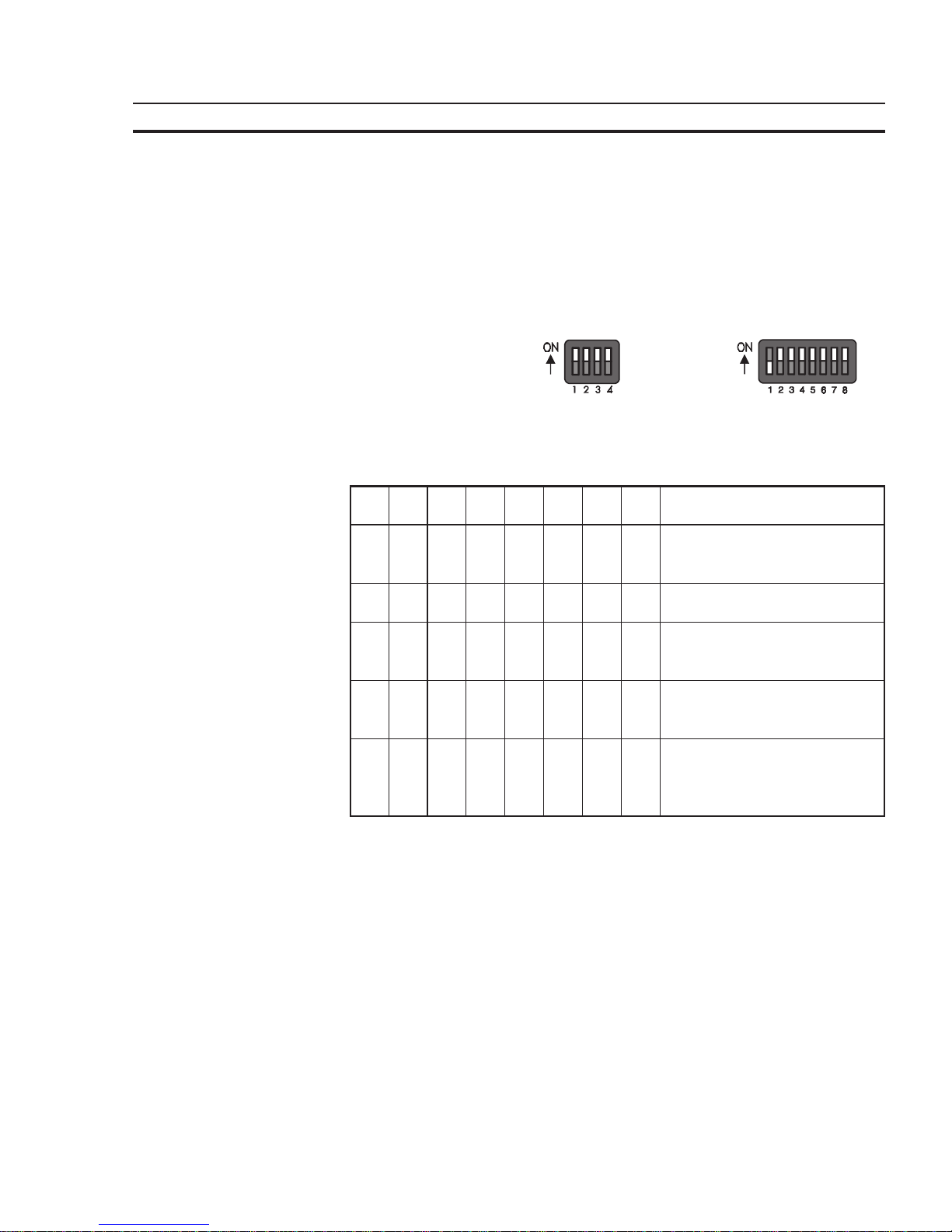
1.8 User-Mode Switch
The user-Mode switch is placed at the side of the terminal NT4S-SF122B-E and at
the rear side of all other terminals.
User-Mode Switch 4 Switches 8 Switches
NT4S-SF121B-E NT4S-SF123B-E
NT4S-SF122B-E NT15S-SF121B-E
NT18S-SF121B-E
The switches S5 to S8 can be used by the operator as needed. The switch positions
are stored at initialization time and afterwards they can be overtaken to the controller.
S1 S2 S3 S4 S5 S6 S7 S8 Function
IX- -XXXXStandard-Mode with PLC (de-
livery state)
IXI -XXXXStandard-Mode without PLC
- I - - XXXXTransparent-Mode with start
and stop code of the keys
- - - I XXXXTransparent-Mode without stop
code of the keys
I - - I XXXXActivate download (deletes ap-
plication memory) and default
contrast setting
Table Legend:
I = Switch position ON
- = Switch positionOFF
X = Switch position irrelevant
Page 56

42
The Terminals of the NT-Series Section 1-9
1.9 Battery
A built-in lithium battery buffers the data in the RAM memory and also supplies the
real-time clock with power. The discharge degree of the battery is monitored constantly to prevent any loss of data.
The battery provides a minimum life of 5 years, even under unfavourable operating
conditions.
If the battery is drained the system message ‘change battery’ is generated.
A new battery is supported by OMRON EUROPE.
Replacing the battery:
The battery can be replaced while the operating voltage is connected to ensure that
the message data and time setting are not lost. Mind the safety instructions!
- Remove the mounting bolts of the 25-pin interface connector
- Remove the fastening screws of the enclosure and remove the enclosure
- Replace the cable fastener, which is used to fasten the battery
- Plug off the cable of the battery and replace the discharged battery
- Plug on the cable of the new battery
- Fasten the new battery on the plastic holder on the printed circuit board
OBSERVE THE CORRECT POLARITY OF (−) AND (+)
- Place the enclosure on the rear side of the terminal
- At first fasten the bolts of the interface connector and at last fasten the screws of
the enclosure properly
Changing the battery may only be performed by qualified and authorized personnel!
Sewage and refuse disposal:
Dispose only drained batteries into the collection box of the community or of the
local dealer. The battery is stated as drained when the message ‘change battery’
appears on the display of the terminal.
To prevent short circuitry in the collection boxes insulate the poles of each battery
with insulation tape or put each single battery into a plastic bag.
Do not put lithium batteries in fire or heat them above 100 !C and do not recharge
them. Danger of Explosion!
Do not open lithium batteries. Danger of Poisoning!
Hazardous voltages can exist inside electrical installations that can pose a danger
to humans. Coming in contact with live parts may result in electric shock!
Electrostatic discharges can damage electronic components! ESD protective measures must be observed!
Page 57

43
The Terminals of the NT-Series Section 1-11
1.10 Fuse
A semiconductor fuse is used to prevent damage to the operating terminal. Once
the fuse has been activated, the device must be disconnected from the supply
voltage to allow the semiconductor fuse to regenerate. With an ambient temperature of 20 !C, the regeneration takes about 20 seconds. The higher the ambient
temperature, the longer the regeneration period.
The semiconductor fuse is not designed to be replaced.
Hazardous voltages can exist inside electrical installations that can pose a danger
to humans. Coming in contact with live parts may result in electric shock!
Electrostatic discharges can damage electronic components! ESD protective measures must be observed!
1.11 Application Memory
A 256 kByte flash memory is used as an application memory for each operating
terminal . This memory area is available to store the user application, the loadable
protocol driver, the fonts and the recipe data. The advantage of the flash memory is
that programming and deleting processes can be carried out directly in the terminal.
Changing the application memory may only be performed by qualified and authorized personnel!
Hazardous voltages can exist inside electrical installations that can pose a danger
to humans. Coming in contact with live parts may result in electric shock!
Electrostatic discharges can damage electronic components! ESD protective measures must be observed!
Page 58

Page 59

45
SECTION 2
Technical Data
This section lists all the electrical and mechanical specifications of the terminals.
2.1 NT4S-SF121B-E ............................................................................ 47
2.2 NT4S-SF122B-E ............................................................................ 48
2.3 NT4S-SF123B-E ............................................................................ 50
2.4 NT15S-SF121B-E ........................................................................... 51
2.5 NT18S-SF121B-E ........................................................................... 53
Page 60

46
Page 61

47
Technical Data Section 2-1
2 Technical Data
2.1 NT4S-SF121B-E
Keyboard a Total of 11 Keys, Mechanical with Tactile Feedback
Divided into
2 Control Keys
4 Function Keys with LEDs and Slide-in Identification Strips
1 Special Key without LED
2 Special Keys with LEDs
2 Editing Keys
Display Backlit LCD Module, 4 Lines with 20 Characters Each,
Display Area 23 × 74 mm (H × W)
with Glare Suppression for Increased Contrast
Interface X3 Variable Baud Rates and Data Formats
600 to 19200 Bd
SER1 RS485, Electrically Isolated Communication
SER1 TTY / 20 mA, Electrically Isolated Communication
SER1 RS232c, Electrically Isolated Communication
SER2 RS232c, Not Electrically Isolated Download/Logging Printer
Central Unit Z80-CPU, 10 MHz, Watchdog Timer, Real-Time Clock, Programmable Interface
Parameters, Temperature Compensation of the Display, Adjustment of Contrast,
Battery Monitoring, User Mode Switch
Memory 256 Kbyte Flash Memory, Application Memory
256 kByte Flash Memory, Firmware
128 Kbyte stat. CMOS-RAM, Battery-Backed
Fuse Semiconductor Fuse
Connection System Plug-in Type, via SubminD Female Connector Strip
Supply Voltage 24 V Direct Voltage, Residual Ripple Max. 10%
Minimum Voltage 19.2 V
Maximum Voltage 30.2 V
Typ. Power Consumption ,0.3 A
Peak Current (10 ms) ,0.5 A
Connected Load , 10 W
Page 62

48
Technical Data Section 2-2
Noise Immunity EC Electromagnetic Compatibility Directive 89/336/EEC
EN 55011 Limit Class B
EN 50081-1 Table A1
EN 50082-2
EN 61000-4-2
EN 61000-4-3
EN 61000-4-4
EN 61000-4-5
EN 61000-4-6
Environmental Test DIN40040 Operation Storage
Code Letter - Temperature KW HU
Code Letter - Humidity F F
Degrees of Protection DIN 40050 Mechanical Degrees of Protection
Front: IP65
Rear: IP20
Front Panel Aluminum, Black Anodized with Affixed Polyester Cover, Circumferential Polyu-
rethane Foam Seal at Rear Side of Front Panel
96.0 × 144.0 × 3.5 mm (H × W × D)
Panel Cutout 82 × 138 mm (H × W)
Mounting Depth 43 mm without Connector
Enclosure Zinc-Coated Steel Plate
Total Weight Approx. 400 g
2.2 NT4S-SF122B-E
Keyboard a Total of 30 Keys, Membrane with Tactile Feedback
Divided into
6 Control Keys
6 Function Keys with LEDs and Slide-in Identification Strips
2 Special Keys with LEDs
3 Special Keys without LEDs
13 Editing Keys
Display Backlit LCD Module, 4 Lines with 20 Characters Each,
Display Area 23 × 74 mm (H × W)
with Glare Suppression for Increased Contrast
Interface X3 Variable Baud Rates and Data Formats
600 to 19200 Bd
SER1 RS485, Electrically Isolated Communication
SER1 TTY / 20 mA, Electrically Isolated Communication
SER1 RS232c, Electrically Isolated Communication
SER2 RS232c, Not Electrically Isolated Download/Logging Printer
Page 63

49
Technical Data Section 2-2
Central Unit Z80-CPU, 10 MHz, Watchdog Timer, Real-Time Clock, Programmable Interface
Parameters, Temperature Compensation of the Display, Adjustment of Contrast,
Battery Monitoring, User Mode Switch
Memory 256 Kbyte Flash Memory, Application Memory
256 kByte Flash Memory, Firmware
128 Kbyte stat. CMOS-RAM, Battery-Backed
Fuse Semiconductor Fuse
Connection System Plug-in Type, via SubminD Female Connector Strip
Supply Voltage 24 V Direct Voltage, Residual Ripple Max. 10%
Minimum Voltage 19.2 V
Maximum Voltage 30.2 V
Typ. Power Consumption ,0.3 A
Peak Current (10 ms) ,0.5 A
Connected Load , 10 W
Noise Immunity EC Electromagnetic Compatibility Directive 89/336/EEC
EN 55011 Limit Class B
EN 50081-1 Table A1
EN 50082-2
EN 61000-4-2
EN 61000-4-3
EN 61000-4-4
EN 61000-4-5
EN 61000-4-6
Environmental Test DIN40040 Operation Storage
Code Letter - Temperature KW HU
Code Letter - Humidity F F
Degrees of Protection DIN 40050 Mechanical Degrees of Protection
Front: IP65
Rear: IP20
Front Panel Aluminum, Black Anodized with Affixed Polyester Cover, Circumferential Rubber
Sealing around rear of front panel
168.0 × 120.0 × 4.0 mm (H × W × D)
Panel Cutout 160 × 112 mm (H × W)
Mounting Depth 40 mm without Connector
Enclosure Zinc-Coated Steel Plate
Total Weight 500 g
Page 64

50
Technical Data Section 2-3
2.3 NT4S-SF123B-E
Keyboard a Total of 30 Keys, Mechanical with Tactile Feedback
Divided into
5 Control Keys
8 Function Keys with LEDs and Slide-in Identification Strips
2 Special Key without LED
2 Special Keys with LEDs
13 Editing Keys
Display Backlit LCD Module, 4 Lines with 20 Characters Each,
Display Area 23 × 74 mm (H × W)
with Glare Suppression for Increased Contrast
Interface X3 Variable Baud Rates and Data Formats
600 to 19200 Bd
SER1 RS485, Electrically Isolated Communication
SER1 TTY / 20 mA, Electrically Isolated Communication
SER1 RS232c, Electrically Isolated Communication
SER2 RS232c, Not Electrically Isolated Download/Logging Printer
Central Unit Z80-CPU, 10 MHz, Watchdog Timer, Real-Time Clock, Programmable Interface
Parameters, Temperature Compensation of the Display, Adjustment of Contrast,
Battery Monitoring, User Mode Switch
Memory 256 Kbyte Flash Memory, Application Memory
256 kByte Flash Memory, Firmware
128 Kbyte stat. CMOS-RAM, Battery-Backed
Fuse Semiconductor Fuse
Connection System Plug-in Type, via SubminD Female Connector Strip
Supply Voltage 24 V Direct Voltage, Residual Ripple Max. 10%
Minimum Voltage 19.2 V
Maximum Voltage 30.2 V
Typ. Power Consumption ,0.35 A
Peak Current (10 ms) ,0.5 A
Connected Load , 10 W
Noise Immunity EC Electromagnetic Compatibility Directive 89/336/EEC
EN 55011 Limit Class B
EN 50081-1 Table A1
EN 50082-2
EN 61000-4-2
EN 61000-4-3
EN 61000-4-4
EN 61000-4-5
EN 61000-4-6
Page 65

51
Technical Data Section 2-4
Environmental Test DIN40040 Operation Storage
Code Letter - Temperature KW HU
Code Letter - Humidity F F
Degrees of Protection DIN 40050 Mechanical Degrees of Protection
Front: IP65
Rear: IP20
Front Panel Aluminum, Black Anodized with Affixed Polyester Cover, Circumferential Sealing
Around Rear of Front Panel
150.0 × 270.0 × 3.0 mm (H × W × D)
Panel Cutout 112 × 232 mm (H × W)
Mounting Depth 48 mm without Connector
Enclosure Zinc-Coated Steel Plate
Total Weight approx. 800 g
2.4 NT15S-SF121B-E
Keyboard a Total of 42 Keys, Mechanical with Tactile Feedback
Divided into
7 Control Keys
16 Function Keys with LEDs and Slide-in Identification Strips
2 Special Key without LED
4 Special Keys with LEDs
13 Editing Keys
Display Backlit LCD Module, 8 Lines with 40 Characters Each,
Display Area 40.4 × 134.0 mm (H × W)
with Glare Suppression for Increased Contrast
Interface X3 Variable Baud Rates and Data Formats
600 to 19200 Bd
SER1 RS485, Electrically Isolated Communication
SER1 TTY / 20 mA, Electrically Isolated Communication
SER1 RS232c, Electrically Isolated Communication
SER2 RS232c, Not Electrically Isolated Download/Logging Printer
Central Unit Z80-CPU, 10 MHz, Watchdog Timer, Real-Time Clock, Programmable Interface
Parameters, Temperature Compensation of the Display, Adjustment of Contrast,
Battery Monitoring, User Mode Switch
Memory 256 Kbyte Flash Memory, Application Memory
256 kByte Flash Memory, Firmware
128 Kbyte stat. CMOS-RAM, Battery-Backed
Page 66

52
Technical Data Section 2-4
Fuse Semiconductor Fuse
Connection System Plug-in Type, via SubminD Female Connector Strip
Supply Voltage 24 V Direct Voltage, Residual Ripple Max. 10%
Minimum Voltage 19.2 V
Maximum Voltage 30.2 V
Typ. Power Consumption ,0.4 A
Peak Current (10 ms) ,0.6 A
Connected Load , 10 W
Noise Immunity EC Electromagnetic Compatibility Directive 89/336/EEC
EN 55011 Limit Class B
EN 50081-1 Table A1
EN 50082-2
EN 61000-4-2
EN 61000-4-3
EN 61000-4-4
EN 61000-4-5
EN 61000-4-6
Environmental Test DIN40040 Operation Storage
Code Letter - Temperature KW HU
Code Letter - Humidity F F
Degrees of Protection DIN 40050 Mechanical Degrees of Protection
Front: IP65
Rear: IP20
Front Panel Aluminum, Black Anodized with Affixed Polyester Cover, Circumferetial Rubber
Sealing at Rear Side of Front Panel
230.0 × 250.0 × 4.0 mm (H × W × D)
Panel Cutout 188 × 204 mm (H × W)
Mounting Depth 50 mm without Connector
Enclosure Zinc-Coated Steel Plate
Total Weight Approx. 1200 g
Page 67

53
Technical Data Section 2-5
2.5 NT18S-SF121B-E
Keyboard a Total of 34 Keys, Mechanical with Tactile Feedback
Divided into
5 Control Keys
12 Function Keys with LEDs and Slide-in Identification Strips
2 Special Key without LED
2 Special Keys with LEDs
13 Editing Keys
Display Backlit LCD Module, 16 Lines with 40 Characters Each,
Display Area 72 × 131 mm (H × W)
with Glare Suppression for Increased Contrast
Interface X3 Variable Baud Rates and Data Formats
600 to 19200 Bd
SER1 RS485, Electrically Isolated Communication
SER1 TTY / 20 mA, Electrically Isolated Communication
SER1 RS232c, Electrically Isolated Communication
SER2 RS232c, Not Electrically Isolated Download/Logging Printer
Central Unit Z80-CPU, 10 MHz, Watchdog Timer, Real-Time Clock, Programmable Interface
Parameters, Temperature Compensation of the Display, Adjustment of Contrast,
Battery Monitoring, User Mode Switch
Memory 256 Kbyte Flash Memory, Application Memory
256 kByte Flash Memory, Firmware
128 Kbyte stat. CMOS-RAM, Battery-Backed
Fuse Semiconductor Fuse
Connection System Plug-in Type, via SubminD Female Connector Strip
Supply Voltage 24 V Direct Voltage, Residual Ripple Max. 10%
Minimum Voltage 19.2 V
Maximum Voltage 30.2 V
Typ. Power Consumption ,0.7 A
Peak Current (10 ms) ,3.0 A
Connected Load , 20 W
Noise Immunity EC Electromagnetic Compatibility Directive 89/336/EEC
EN 55011 Limit Class B
EN 50081-1 Table A1
EN 50082-2
EN 61000-4-2
EN 61000-4-3
EN 61000-4-4
EN 61000-4-5
EN 61000-4-6
Page 68

54
Technical Data Section 2-5
Environmental Test DIN40040 Operation Storage
Code Letter - Temperature KW HU
Code Letter - Humidity F F
Degrees of Protection DIN 40050 Mechanical Degrees of Protection
Front: IP65
Rear: IP20
Front Panel Aluminum, Black Anodized with Affixed Polyester Cover, Circumferential Sealing
Around Rear of Front Panel
190.0 × 330.0 × 3.0 mm (H × W × D)
Panel Cutout 152 x 292 mm (H x W)
Mounting Depth 60 mm without Connector
Enclosure Zinc-Coated Steel Plate
Total Weight approx. 1500 g
Page 69

55
SECTION 3
Operating Modes
This section describes the two available operation modes, the standard mode and the transparant mode
and indicates how to select the operation mode.
3.1 Setting the Operating Mode ................................................................. 57
Page 70

56
Page 71
57
Operating Modes Section 3-1
3 Operating Modes
There are two types of operating modes available in the operating terminals, the
standard mode of operation and the transparent mode of operation.
Terminals operating in the transparent mode represent full-size ANSI-terminals.
Each key generates a press and release code, which will be transmitted via the
interface SER1 in the form of an ASCII character. The displays and the key LEDs
are controlled via ESC sequences. The number of character sets and character
attributes varies with the type of display. For a detailed description please refer to
the chapter ‘Transparent Mode’.
In the standard mode of operation, the entire operating system is integrated in the
terminal. The standardized operating concept
completely frees the connected controller from any operator guidance tasks as well as data display.In standard mode, a
decoding of the keys or selection of masks from within the controller is not required.
3.1 Setting the Operating Mode
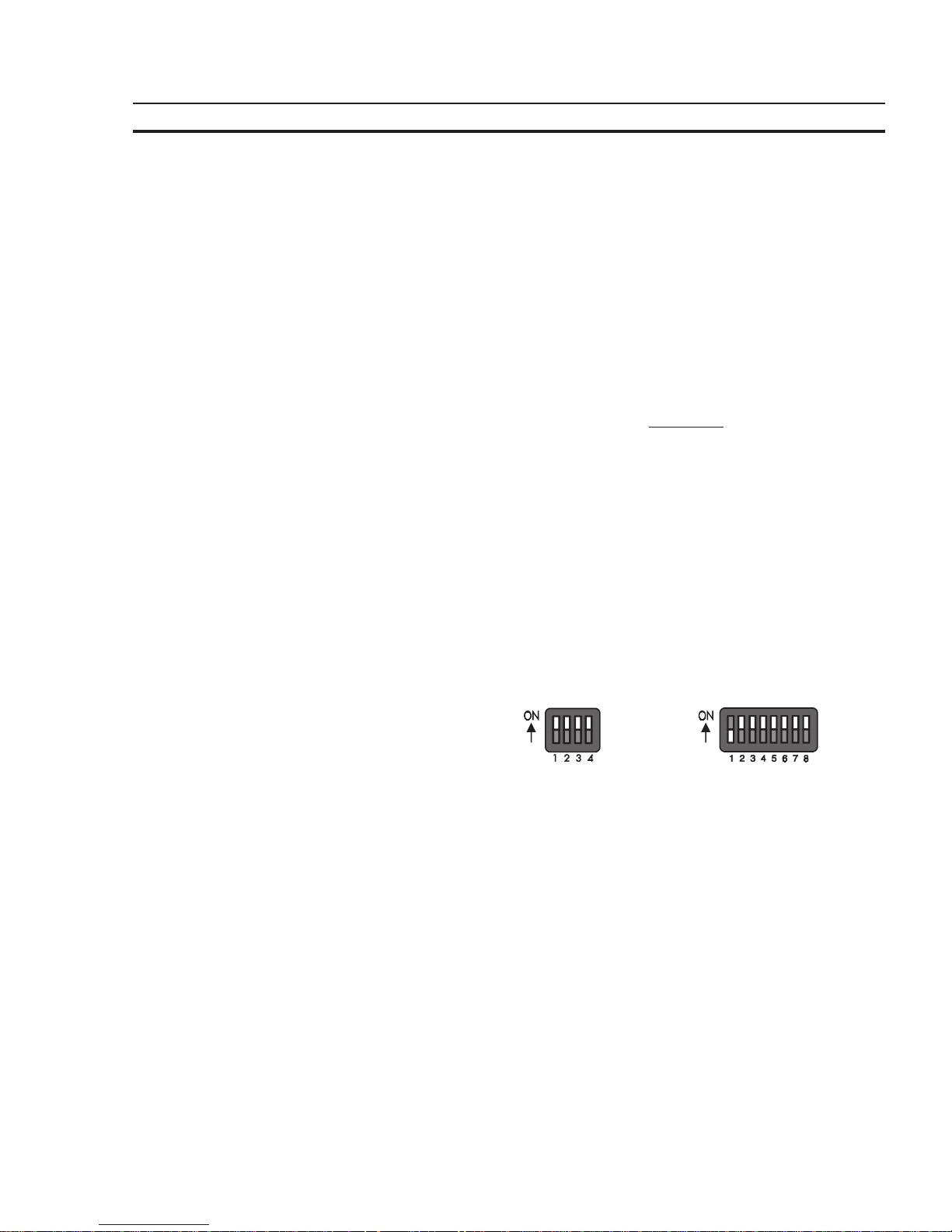
The operating mode can be set by means of the User-Mode-Switch. The terminals
are factory-set to the standard mode of operation.
The user-mode switch is accessible at the side of the terminal NT4S-SF122B-E
and at the rear side of all other operating terminals.
User-Mode Switch 4 Switches 8 Switches
NT4S-SF121B-E NT4S-SF123B-E
NT4S-SF122B-E NT15S-SF121B-E
NT18S-SF121B-E
Page 72

58
Operating Modes Section 3-1
The switches S5 to S8 can be used by the operator as needed. The switch positions
are stored at initialization time and afterwards they can be overtaken to the controller.
S1 S2 S3 S4 S5 S6 S7 S8 Function
IX- -XXXXStandard-Mode with PLC (delivery state)
IXI -XXXXStandard-Mode without PLC
- I - - XXXXTransparent-Mode with start and stop code
of the keys
- - - I XXXXTransparent-Mode without stop code of the
keys
I - - I XXXXActivate download (deletes application
memory) and default contrast setting
Table Legend:
I = Switch position ON
- = Switch position OFF
X = Switch position irrelevant
Page 73

59
SECTION 4
Standard Mode
This section describes the standard operation mode in detail. This section contains all detailed information to understand all features of the terminal in order to make a terminal application.
4.1 Setting the Operating Mode ................................................................. 63
4.2 Startup Process.............................................................................. 64
4.2.1 Startup Process without a Valid User Description ..................................... 65
4.3 Communication in the Standard Mode ....................................................... 65
4.4 Operating Concept .......................................................................... 65
4.4.1 Mask Structure ...................................................................... 65
4.4.2 External Mask Selection ............................................................. 66
4.4.3 Password Protection, Access Authorization ........................................... 66
4.4.3.1 Reactivating the Password Protection........................................ 69
4.4.3.2 Password Management...................................................... 69
4.4.3.3 Password Mask and Password Functionality.................................. 69
4.5 Masks ...................................................................................... 70
4.5.1 Mask Parameters .................................................................... 70
4.5.2 System Masks ....................................................................... 70
4.5.2.1 Setup Mask................................................................. 71
4.5.2.1.1 Password Protection - Setup Mask ................................ 71
4.5.2.1.2 Function Without the Setup Mask ................................ 71
4.5.2.2 Start Mask.................................................................. 71
4.5.2.3 Password Mask ............................................................. 72
4.5.2.4 I/O Mask ................................................................... 72
4.6 Variables ................................................................................... 72
4.6.1 Output Variables .................................................................... 73
4.6.1.1 ‘Decimal Number’ Representation........................................... 76
4.6.1.1.1 ‘Standard’ Variable Type ........................................ 76
4.6.1.1.2 ‘Timer’ Variable Type ........................................... 76
4.6.1.1.3 ‘Counter’ Variable Type ......................................... 77
4.6.1.1.4 ‘BCD-Number’ Variable Type ................................... 78
4.6.1.2 ‘Alphanumerical’ Representation ........................................... 78
4.6.1.3 ‘Selection Text’ Representation ............................................. 78
4.6.1.4 ‘Selection Image’ Representation ........................................... 79
4.6.1.5 ‘Floating Point Number’ Representation .................................... 80
4.6.1.6 ‘Hexadecimal Number’ Representation ..................................... 80
4.6.1.7 ‘Binary Number’ Representation ............................................ 81
4.6.1.8 Bar Representation ........................................................ 81
4.6.1.9 Curve Representation (Trendline) ........................................... 82
4.6.2 Input Variables ...................................................................... 83
4.6.3 System Variables .................................................................... 85
4.6.3.1 Basic Functions ............................................................. 85
4.6.3.2 Communication SER1 ...................................................... 87
4.6.3.3 Error Statistics SER1 ....................................................... 89
4.6.3.4 Communication SER2 ...................................................... 90
4.6.3.5 Real-Time Clock ........................................................... 92
4.6.3.6 Serial Message System ...................................................... 93
Page 74

60
4.6.3.7 Parallel Message System .................................................... 96
4.6.3.8 Printer Control ............................................................. 98
4.6.3.9 Menu Control / Keys........................................................ 99
4.6.3.10 Password ................................................................... 106
4.6.3.11 Recipes .................................................................... 107
4.6.3.12 Running Time Meter........................................................ 112
4.6.3.13 Loop-Through Operation ................................................... 112
4.6.3.14 Loadable Font .............................................................. 113
4.6.3.15 Maintenance................................................................ 113
4.6.3.16 Editors ..................................................................... 114
4.6.3.17 Help ....................................................................... 114
4.6.4 Editors .............................................................................. 115
4.6.4.1 Decimal Number Editor .................................................... 116
4.6.4.2 Floating Point Number Editor............................................... 117
4.6.4.3 Hexadecimal Editor......................................................... 118
4.6.4.4 Alphanumerical Editor...................................................... 118
4.6.4.5 Selection Text Editor ....................................................... 119
4.6.4.6 Selection Image Editor...................................................... 119
4.6.4.7 Table Editor................................................................ 119
4.6.5 External Data Release ............................................................... 121
4.6.6 PLC-Handshake ..................................................................... 123
4.6.7 Refreshing One-Time Output Data ................................................... 123
4.6.8 Modified Data ....................................................................... 124
4.6.8.1 Input Plausibility Check..................................................... 124
4.7 Graphics.................................................................................... 124
4.7.1 Images .............................................................................. 124
4.7.2 Graphics on Operating Terminals..................................................... 125
4.7.2.1 Background Images......................................................... 125
4.8 Recipes ..................................................................................... 126
4.8.1 Structure of a Recipe ................................................................ 127
4.8.2 Processing Recipes and Data Sets..................................................... 127
4.8.2.1 Selecting a Recipe .......................................................... 128
4.8.2.2 Selecting a Data Set......................................................... 128
4.8.2.3 Copying a Data Set ......................................................... 128
4.8.2.4 Deleting a Data Set ......................................................... 129
4.8.2.5 Modifying a Data Set ....................................................... 129
4.8.3 Data Set Transfer to / from a Controller .............................................. 129
4.8.3.1 Transfer to a Controller ..................................................... 129
4.8.3.2 Transfer from a Controller .................................................. 131
4.8.4 Transferring Data Sets to / from a PC................................................. 132
4.8.4.1 Transfer to a PC ............................................................ 132
4.8.4.2 Transfer from a PC ......................................................... 133
4.8.4.3 Structure of a Data Set File ................................................. 133
4.8.5 Printing Data Sets ................................................................... 135
4.8.6 Memory Requirements for Storing Data Sets.......................................... 136
4.9 Message System............................................................................. 136
4.9.1 Internal Messages.................................................................... 136
4.9.1.1 System Messages............................................................ 136
4.9.1.1.1 Suppressing the Display of System Messages ...................... 140
4.9.1.2 Error Messages ............................................................. 140
Page 75

61
4.9.2 External Messages ................................................................... 146
4.9.2.1 Structure of an External Message............................................ 146
4.9.2.1.1 Assigning Message Numbers...................................... 146
4.9.2.1.2 Message Buffer Size.............................................. 147
4.9.2.1.3 Message Texts, Variables ......................................... 147
4.9.2.1.4 Sorting Messages................................................. 148
4.9.2.1.5 Message Priority for Direct Display ............................... 148
4.9.2.1.6 Printing the Message Memory .................................... 148
4.9.2.2 Message Mask, Status Message Mask ........................................ 149
4.9.2.2.1 Direct Selection of the Message Mask............................. 150
4.9.2.2.2 Output Formats for Messages..................................... 150
4.9.2.2.3 Zooming Messages............................................... 151
4.9.2.2.4 Acknowledging Messages......................................... 151
4.9.2.3 Serial Message System ...................................................... 151
4.9.2.3.1 Full-Page Message Output........................................ 152
4.9.2.3.2 Messages Directly to a Logging Printer............................ 152
4.9.2.3.3 Erasing the Message Memory Externally .......................... 152
4.9.2.3.4 Information about the Serial Message System ..................... 153
4.9.2.4 Parallel Message System (Status Messages) .................................. 154
4.9.2.4.1 Number of Bytes for Status Messages ............................. 154
4.9.2.4.2 Image of the Status Messages ..................................... 154
4.9.2.4.3 Time-Controlled Transfer of the Status Message................... 155
4.9.2.4.4 Event-Controlled Transfer of the Status Message .................. 155
4.10 Help System ................................................................................ 155
4.10.1 Default Help Text ................................................................... 155
4.10.2 Help Text For Masks ................................................................ 156
4.10.2.1 Help Text for the Message Mask ............................................ 156
4.10.3 Help Text For Variables ............................................................. 156
4.11 Function Keys .............................................................................. 156
4.11.1 Direct Selector Keys ................................................................. 156
4.11.2 Function Keys of the Controller ...................................................... 157
4.11.3 Soft Keys............................................................................ 157
4.11.3.1 Reaction Time of Function and Soft Keys.................................... 158
4.11.3.2 Control Keys as Function Keys .............................................. 158
4.11.4 Function Keys Controlling Parallel Outputs ........................................... 158
4.11.5 Status LEDs in the Function Keys .................................................... 158
4.12 System Parameters .......................................................................... 159
4.12.1 System Parameters: General Parameters .............................................. 159
4.12.2 System Parameters: Poll Area ........................................................ 159
4.12.3 System Parameters: Terminal Clock .................................................. 160
4.12.4 System Parameters: Running Time Meter ............................................. 160
4.12.5 System Parameters: Message System.................................................. 160
4.12.6 System Parameters: Variant Buffer ................................................... 160
4.12.7 System Parameters: Password Management ........................................... 160
4.12.8 System Parameters: Printer Interface ................................................. 160
4.12.9 System Parameters: Gateway ......................................................... 161
4.12.10 System Parameters: Data Set Transfer ................................................ 161
4.12.11 System Parameters: Parallel Outputs.................................................. 161
4.13 Version Number ............................................................................ 161
4.14 Running Time Meter ........................................................................ 161
4.15 Parallel Outputs............................................................................. 163
4.16 Screen Saver ................................................................................ 163
Page 76

62
4.17 Image of the Mask Number.................................................................. 164
4.18 Image of the Mode Selector Switch .......................................................... 164
4.19 Terminal Clock ............................................................................. 164
4.19.1 Image of Date and Time ............................................................. 165
4.20 Read Coordination Byte..................................................................... 166
4.20.1 Editing Request Bit (Bit ‘EA’) ....................................................... 166
4.20.2 Editing Status Bit (Bit ‘EZ’).......................................................... 166
4.20.3 Refresh Request Bit (Bit ‘RA’)....................................................... 167
4.20.4 Liveness Flag (Bit ‘LM’) ............................................................. 167
4.20.5 Data Set Download Active (Bit ‘DDA’) .............................................. 167
4.21 Write Coordination Byte .................................................................... 168
4.21.1 External Data Release (Bit ‘ED’)..................................................... 168
4.21.2 Refresh Acknowledgement (Bit ‘RQ’) ................................................ 168
4.21.3 Resetting the Password............................................................... 168
4.21.4 Liveness Flag (Bit ‘LM’) ............................................................. 168
4.21.5 Data Set Download Release (Bit ‘DDF’).............................................. 169
4.22 Cyclic Poll Area............................................................................. 169
4.22.1 Byte-Oriented ....................................................................... 170
4.22.2 Word-Oriented ...................................................................... 171
4.22.3 Image of the LEDs .................................................................. 172
4.22.4 Serial Message Channel ............................................................. 172
4.22.5 Polling Time......................................................................... 173
4.22.6 Size of the Poll Area ................................................................. 173
4.23 Control Codes .............................................................................. 173
4.23.1 Triggering Data Set Printouts ........................................................ 173
4.23.2 Setting the Clock in the Operating Terminal .......................................... 173
4.23.3 Transferring Data Sets from the Controller to the Terminal............................ 174
4.23.4 Transferring Data Sets from the Terminal to the Controller............................ 174
4.23.5 Transferring Data Sets from the Controller to the Terminal (Individually).............. 174
4.23.6 Refreshing the Message System ...................................................... 175
4.24 Cyclic Variables............................................................................. 175
4.25 Interface Parameters ........................................................................ 175
4.26 Variable Definition.......................................................................... 175
4.26.1 Variable List ........................................................................ 176
4.27 Application Programming ................................................................... 176
4.27.1 Configuring the System .............................................................. 177
4.27.2 Programming Systems................................................................ 178
4.27.3 Project Description .................................................................. 178
4.27.3.1 Multilingual Projects ........................................................ 178
4.27.3.2 Variants of a Project ........................................................ 179
4.27.4 Project Documentation .............................................................. 179
4.27.4.1 Creating Documentation .................................................... 179
4.27.5 Project Back-up...................................................................... 180
4.27.6 Optimizing the Transmission Rate .................................................... 180
4.28 Downloading the User Description........................................................... 180
4.28.1 Downloading with Windows.......................................................... 182
4.28.2 Application Memory................................................................. 182
4.28.3 Loading an Application .............................................................. 182
4.28.4 Activating the Download Function using the Software................................. 183
4.28.5 Activating the Download Function using the Hardware................................ 183
4.28.6 Automatic Download Function ....................................................... 184
4.28.7 Download Cable..................................................................... 184
4.29 Simulation without the Controller............................................................ 184
Page 77

63
Standard Mode Section 4-1
4 Standard Mode
The standard mode is the mode of operation in which the terminals are most commonly used and that provides the highest performance. In this mode of operation,
the terminals act as intelligent peripheral devices for the controller by performing
controlled pre-processing of the visualization data, thus completely relieving the
connected controller of all operating tasks. This reduces the programming effort
required by the user, the run time and memory required in the PLC.
Communication processors have been dispensed with in the PLC and programming unit interfaces have been used throughout, making the PLC connection very
economical. The operating concept is a universal one, thanks to the large number
of supported protocols. Operation of the machine has been made independent of
the type and manufacturer of the controller.
The standard mode is supported by every operating terminal. The system’s flexibility means you can customize all menus and dialogs according to your particular
application. Extremely sophisticated operator guidances can be configured with
the aid of masks, system variables and control and function keys. In standard
mode, all functions which can be executed with the terminal, mask contents, texts,
messages and variables are stored in the user description (mask definition). After
the programming phase is complete, the user description is stored in the operating
terminal’s Flash memory.
In the description which follows, the term ‘
user
’ refers to individuals who configure
or program the operator interface, while ‘
operator
’ refers to individuals who monitor
and operate the data of the installation on site.
4.1 Setting the Operating Mode
The standard mode of operation can be set with the user-mode switch. Turn off the
terminal before selecting the mode of operation.
All terminals are factory-set to the standard mode.
The ON/OFF positions on the mode selector switch are marked.
The selected mode of operation becomes active as soon as power is supplied.
Position of the switch for the standard mode:
S1 ON S5 not used
S2 not used S6 not used
S3 OFF S7 not used
S4 OFF S8 not used
Fig. 1: User-mode switch
Page 78

64
Standard Mode Section 4-2
4.2 Startup Process
All LEDs in the terminal are initially lit when the power is applied. A system-test is
then performed that includes testing and initialization of the modules in the operating terminal. Various system and error messages may be output during this system-test. If the application memory contains a valid user description, the first mask,
the Start-Mask, or the mask specified in the language parameters as the mask to
be used as the Start-Mask will appear on the display.
This mask is displayed for 5 seconds (fixed time setting). This time can be used by
the operator to visually inspect the LEDs and the screen for proper functioning.
After this time period, the Main Mask or the mask specified in the language parameters as the Main Mask is displayed. This mask is the first mask of the operator
guidance.
If the Enter keyis pressed while the Startup Mask is displayed, the Setup Mask will
appear on the display. This Setup Mask can be used to set the parameters for the
interface and the operating terminal.
If the Enter key is pressed before the Startup Mask is displayed, an error message
will be generated during the keyboard test.
.......The self-test performed on the keyboard during
the terminal start-up has detected that a key is
pressed. Comply with the request and release
the key. If this message is generated when no
key is pressed, this indicates a defective keyboard. Generally, the message will disappear
after releasing the key/keys.
A longer delay may occur before the Startup Mask is displayed if the statistics
memory contains a large number of messages from the serial message system.
This time period (initialization period) is required to set up the structures for message management, which will then enable faster sorting of messages later. During
the initialization phase, the following message is displayed:
.......When the terminal is switched on, the mes-
sages that are present in the terminal are sorted. This process requires a certain length of
time (initialization time).
Page 79

65
Standard Mode Section 4-4
4.2.1 Startup Process without a Valid User Description
The system-test performed on the application memory will detect whether a module is missing, defective or of the wrong type. This is then indicated to the operator
by the following message:
If the memory test establishes that the right type of Flash memory is used but that it
does not contain a valid user description, the Flash memory will be erased and the
terminal will automatically switch to the download operating mode. The following
messages appear on the display indicating the various phases:
The message ‘DOWNLOAD 1’ remains on the display to indicate that the terminal
is now ready to receive a valid user description via the download interface.
Until the memory contains a valid user description, communication with a controller
will not take place, nor will the keyboard be operational. Once a valid user description has been downloaded, the terminal becomes active.
4.3 Communication in the Standard Mode
In standard mode, any interface except the interfaces for the logging printer and the
parallel outputs can be used for communication between the PLC (host computer,
etc.) and the operating terminal. The interface labeling, however, always depends
on the connected counter part or the network.
See relevant chapters in the manual for a more detailed description of the various
interfaces.
4.4 Operating Concept
The operating concept of the terminal has been designed to allow the operator to
access all masks - and thus all the data - quickly and easily.
A number of means are available to the user to help guide the operator through the
mask system.
4.4.1 Mask Structure
By means of the programming system, a network of I/O masks without a real hierarchical structure is formed. I/O masks are located at the nodes in the network and
contain a selection field which is used to call up other masks by their names. It is
possible to access any other I/O mask from an I/O mask by using the control and
function keys.
Page 80

66
Standard Mode Section 4-4
4.4.2 External Mask Selection
Mask calls from the controller are handled in the same way as messages. This
requires simply that 8000H is added to the desired mask number prior to transfer.
When the same number is assigned to a mask and message, both the mask and
the message are called up during external mask selections.
This effect can be used to provide help in a mask. Otherwise, ensure that different
numbers are used for masks and messages.
A mask called up externally is considered selected once the desired mask number
appears in the variable ,Image of Mask Number.. The acknowledgement from
the serial message channel is not a reliable confirmation of the mask output.
Example 1: Mask number and message number are not identical
A project comprises masks with numbers ranging from 100 to 200; the first message has the number 10.
Mask 118 is to be called up by the controller.
The following adding operation must be performed in the controller:
118 + 8000H = 76H + 8000H = 8076H.
The value 8076H must be written to the address of the serial message channel.
Only mask 118 is displayed.
Example 2: Mask number and message number are identical
A project comprises masks with numbers ranging from 1 to 100; the first message
has the number 10.
Mask 50 and serial message 50 are to be called up by the controller.
The following adding operation must be performed in the controller:
50 + 8000H = 32H + 8000H = 8032H.
The value 8032H must be written to the address of the serial message channel.
Both the mask 50 is displayed and message 50 are written to the message buffer.
4.4.3 Password Protection, Access Authorization
The operating concept incorporates a password protection function. Password
protection prevents masks from being accessed and the data they contain from
being altered without proper authorization. The protective function is available in
every operating terminal. It is obtained by assigning access levels to masks and by
using passwords.
Unless otherwise specified by the programmer, the access levels of all masks automatically default to the lowest level (=0), i.e. no password is required to access all
masks with this access level.
Two authorization levels, referred to as the edit level and the view level, are assigned to every password.
View level means that the next mask can be viewed after entering the password but
the values in it can also not be edited.
Edit level means that the mask can be viewed after entering the password and the
values in it can be edited.
Page 81

67
Standard Mode Section 4-4
Up to eight different passwords with a length of up to 11 characters can be defined.
When defining the passwords, the access authorizations should be entered in a
hierarchical structure.
Example:
- password for the manufacturer of the system, machine, etc.
- password for servicing on site
- password for the machine setter, master craftsman, foreman etc.
- password for the system operator
The following figure illustrates how the access levels, edit and view levels work:
Fig. 2: Access levels
An access level (represented here by the height (1) of the walls) can be assigned to
every mask and a view level (length of ladder 2) and edit level (length of ladder 3)
can be assigned to every password.
A password must be entered for viewing onlyof a mask (5) that has been assigned
an access level (access level is greater than 0). The password must have been
assigned a view level (ladder 2) high enough to be able to get over the access level
(view wall). The mask (5) can then be viewed (through window 4) but the variable
values can not be edited.
For viewing and editing the variable values in a mask (5), a password must be
supplied which has a view level (ladder 2) and an edit level (ladder 3) that are both
high enough.
The following rules apply to passwords:
- Access is permitted if the view and edit level values are greater than or equal to
the values specified for the access level.
- The edit level must be equal to or less than the view level.
- The higher the values for the view level and edit level, the higher the degree of
authorization.
- The valid range of values for the view level and edit level is 0 to 255.
- The default setting for both is 0.
Page 82

68
Standard Mode Section 4-4
The Data Release key will have no function if pressed with an insufficient edit level.
The password can be entered in any I/O mask. Note that the Setup Mask is an
exception. The system variable MskchgPasswd is designed to prompt for password entry. If the Password Editor is selected in the programming system, passwords will not appear as they are entered on the terminal. Instead the character ‘X’
appears for every character that is entered.
Example:
Enter PASSWORD: XXXX
This example illustrates hidden entry of a 4-digit number. If an invalid password is
entered, the authorization levels will automatically reset to 0.
It is recommended that at least one password - the master password - is programmed with the highest authorization level. The first password entered in the
password list via the programming system is the master password and as such has
a special function. The master password is unique in that it can not be changed on
the operating terminal. Furthermore, it can be used to reset all modified passwords
to the default values entered in the programming system.
Example:
Mask 5 access level = 10
Mask 6 access level = 20
Mask 7 access level = 30
Password 4712 Edit level = 15 View level = 25
Once the password ‘4712’ has been entered, the following accesses are permitted:
- Mask 5 will be displayed, editing of values is authorized
- Mask 6 will be displayed, editing of values is
not authorized
- Mask 7 will
not be displayed, editing of values is not authorized
The access level for the Startup Mask is always 0.
The Setup Mask is an exception with regards to the password and external data
release functions. Since no communication is taking place when the Setup Mask is
displayed, the external data release function is not applicable. To restrict access,
passwords must be used. By defining the first editable variable in the Setup Mask
as a Password Editor, all further variables can be protected against unauthorized
access. The view level does not apply when accessing the Setup Mask. Viewing is
always permitted if a value less than or equal to 254 is selected for the access level
of the Setup Mask.
The edit level for all variables of the Setup Mask, with the exception of the Password Editor, is the same as that defined as the access level.
Access to the mask is always denied if an access level of 255 is defined for the
setup mask. This means that it will no longer be displayed during initialization of the
terminal and can therefore not be selected. However, all terminal-specific parameters can also be edited in any I/O mask. The new parameters become effective by
restarting the terminal or with the system variable Boot.
Page 83

69
Standard Mode Section 4-4
4.4.3.1 Reactivating the Password Protection
The access authorization for a mask or variable is reset whenever
- the operating terminal is switched off and turned back on
- an incorrect password is entered
- bit 2 in the ,Write Coordination Byte. is set
- the system variable MskchgResPasswd is activated
- the option Reset Password in the mask parameters of the password-protected
mask is selected.
4.4.3.2 Password Management
Passwords are stored in the operating terminal’s Flash memory. These are the
default passwords that are used when the terminal is started up initially after a
download. At the same time, the passwords are stored in the operating terminal’s
RAM.
The passwords stored in the flash memory can be reactivated by writing to the
system variable FlashPasswd.
Every password (except for the master password = first password in the list) can be
edited from the terminal. For this process, the password to be edited is written to the
system variable MskchgPasswd first. The new password is then written twice to
the system variable ChangePasswd. If both entries for the new password are
identical, the password will become effective immediately; otherwise, a system
message will be displayed and the password reset.
Passwords are stored and compared as 11-character strings. The passwords are
entered with the Alphanumerical Editor.
Passwords are only globally programmable (not language-specifically).
4.4.3.3 Password Mask and Password Functionality
- It is possible to create a special mask which requests entry of a password. This
password mask is then displayed whenever an attempt is made to call up a
password-protected mask without first entering a password with sufficient authorization. When a password with sufficient authorization is entered into this
mask, the previously selected password-protected mask is called up once the
Data Release key is pressed. There are no restrictions with respect to the remaining mask contents (texts, further variables, soft keys, etc.).
- You can specify for every mask separately whether the password protection is
to be reactivated after the mask is exited.
- For those cases where no valid password has been entered, an option to exit the
mask must be provided. The Cursor home key can be programmed to perform
this function, for example.
- If no such mask has been created to prompt for password entry, the operator will
be required to enter the password in masks specifically designed for this purpose.
- The entire password protection can be deactivated by setting the system variable PasswdInactive to the value 1. The operating terminal will then act as if all
masks were created with an edit and view level of 0. The system variable is
battery-backed, so deactivation will therefore still be in effect after the operating
terminal is restarted.
Page 84

70
Standard Mode Section 4-5
4.5 Masks
In conjunction with the operating system, the term ‘mask’ always refers to the contents of one screen. The size of masks therefore varies from operating terminal to
operating terminal.
Masks with a specific functionality form the basic elements of the operator guidance. The first step when programming a mask is to specify its functionality. The
process of designing the operator guidance is greatly simplified by the restricted
number of different mask types.
The following mask types are available in the operating concept:
- Setup Mask (system mask)
- Start Mask (system mask)
- Password Mask (system mask)
- Main Mask (system mask)
- I/O Mask (user mask)
4.5.1 Mask Parameters
The number of mask parameters that is available for a specific mask depends on
the mask type. The mask parameters determine the functionality of the control keys
in the operator guidance. Any mask parameters which are not required may remain
unassigned. If no mask parameters at all are programmed, only the function keys
or external mask selection can be used to exit the mask in question.
The functionality of the control keys specified in the mask parameters is subject to
access control of the password system. This prevents unauthorized access to
masks via the control keys.
In addition to the control key functionality, the mask parameters also contain the
access level definition. The access level indicates the minimum value that a password (view level, edit level) must have to be authorized to access a mask and edit
its values. The default value used for the access level is ‘0’ (meaning free access).
A selected Automatic Data Release option in the mask parameters will allow the
operator to supply input into the mask without having to press the Data Release key
first.
An option for automatic reactivation of the password protection is also available in
the mask parameters to ensure that the password has to be reentered when a
password-protected mask is called up again.
4.5.2 System Masks
System masks facilitate initial programming. They also get your system up and
running directly. This makes the initialization phase an integral part of the user
description. Any mask can be selected as a system mask. System masks are basically I/O type masks with a few restrictions. These restrictions result from the operator-prompted initialization phase and the fact that communication to the controller is not yet established.
The system masks Setup Mask and Start Mask can not be accessed via external
mask selection!
Page 85

71
Standard Mode Section 4-5
4.5.2.1 Setup Mask
Only terminal-specific parameters can be defined in the Setup Mask. This is because
no communication takes place with the connected controller while the Startup Mask and Setup Mask are displayed. The external data release therefore has
no function. To protect data, a password must be assigned.
From the operator guidance, the Setup Mask and Startup Mask can be reached
through the function keys, provided they have not been assigned an access level.
After the masks are exited, however, the terminal is not reinitialized.
Examples of terminal-specific parameters:
- Printer interface settings
- Default contrast/default intensity setting of the display
- Date and time settings
- Activation of the download function.
4.5.2.1.1 Password Protection - Setup Mask
The Setup Mask is an exception with regard to password protection.
To password-protect the Setup Mask, the system variable MskchgPasswd must
be set up as the first variable which can be edited in the Setup Mask. A password
can be input regardless of the access level (with the exception of the access level
255).
For the setup mask, the access level applies to the edit level only, meaning that its
contents are always visible to the operator.
4.5.2.1.2 Function Without the Setup Mask
If the Setup Mask is not needed, its access level can be set to the value 255, thus
preventing access to the Setup Mask via the Start Mask (using the Data Release
key).
4.5.2.2 Start Mask
The Start Mask is displayed for around 5 seconds after the terminal is switched on.
This is a fixed time setting; the startup process can not be changed.
With regards to the mask design, the user can only design the text to be displayed in
the mask. Any combination of characters, character sizes and text attributes can be
chosen in the programming system for this purpose.
Only system variables can be output in the Start Mask. Variable input is not possible due to the time restriction. While the Start Mask is displayed, the Setup Mask
can be called by pressing the Data Release key. However, this is not possible if the
access level for the setup mask is set to 255.
Some examples of information that may be chosen to be displayed in the Start
Mask are listed below:
- address for servicing
- machine type
- version number of the program
Page 86

72
Standard Mode Section 4-5
4.5.2.3 Password Mask
The password mask is an I/O type of mask. The functionality is as illustrated in the
password description.
4.5.2.4 I/O Mask
As a basic type of mask, the I/O mask offers a broad range of functions - enough in
fact for configuring complete operator guidances based entirely on it.
I/O masks provide the following options:
- Selection of menus
- Definition of data formats
- Scaling of values
- Output of values once or cyclically
- Text display
- Message output
- Direct selection of up to five adjacent masks with the control keys
- Display of large mask contents over several screen pages
- Display of values in tables
Key Functions in the I/O Mask
Key: Cursor up Can be programmed freely to select adjacent masks
Key: Cursor down Can be programmed freely to select adjacent masks
Key: Cursor left Can be programmed freely to select adjacent masks
Key: Cursor right Can be programmed freely to select adjacent masks
Key: Cursor home Can be programmed freely to select adjacent masks.
Exits the I/O mask for the higher-level menu.
Key: Data Release Switches into the Editor and exits the Editor
Key: Enter Only has a function in conjunction with the Editor
Key: ?, Help Displays the help text specified for the mask for as long
as the key is held down
4.6 Variables
The number of valid variable types is determined by the connected controller. All
standard variable types which are commonly used are supported by the operating
terminals. The data type that is used also determines the valid range of values and
number of significant digits.
Variable Type Size Range of Values
Bit 1 bit [0, 1]
Byte 1 byte [-128 to +127]
Byte 1 byte [0 to 255]
Word 2 bytes [-32768 to +32767]
Word 2 bytes [0 to 65535]
Lword 4 bytes [-2147483648 to +2147483647]
Lword 4 bytes [0 to 4294967295]
Lword 4 bytes [±1.2 * 10
–38
to ± 3.4 * 10
+38
]
ASCII 42 bytes [0 to 255]
Page 87

73
Standard Mode Section 4-6
4.6.1 Output Variables
Output variables are numerical or alphanumerical data stored in the memory of the
connected controller. The variables are retrieved from the controller whenever required, and output on the display at the programmed location according to the
defined method of representation, formatting and scaling. Generally, a distinction
is made between displaying one-time variables (variables are transferred only
once and are then displayed) or at cyclic intervals (variables are continually updated while displayed). The character attributes that are available depend on the
display type of the operating terminal.
One-Time Output Variables or Cyclic Output Variables:
Pure output variables are transmitted by the controller
only once and are displayed
in the mask. This method offloads the communication process and is suitable for all
variables such as setpoint values, constant values and parameters that change
either rarely or never. All output variables can be displayed on a scaled and formatted basis.
Cyclic output variables are used to display actual values, in other words values
which vary continually while a mask is displayed. The cycle time (and thus the
intervals at which the displayed actual values are refreshed) corresponds to the
polling time predefined by the user.
Data transfer between the operating terminal and the PLC can be offloaded
by using variables of the same data type only (data word, flag word, input
word, flag word) and by using continuous addresses within one mask.
Cyclic output variables can also be scaled and formatted. Note that the display of
floating point numbers requires more computing time when the values are scaled.
These will therefore not be displayed in ‘real time’. For this reason, the cycle times
selected here should be . 500 ms.
Also note that the larger the amount of cyclic data for transfer, the longer the response time to new values from the PLC. As a result, longer polling times are required.
Formatted Output:
Formatting a numerical variable allows the display format of the variable to be
adapted to the output range of values. Formatting includes the number of digits to
be displayed, the number of post-decimal places (fractional digits) and whether
signs are to be used or not. The number of post-decimal places gives the operator
the impression that a division has been performed. A division is not actually carried
out, however. The variable in the controller must be available in the appropriate
(higher) resolution.
Example:
Actual value of a length in the controller:
Word variable Range of values 0 to 65535
Resolution 1/100 mm
Display of actual values on the operating terminal:
Display range 0.00 to 655.35 mm
Page 88

74
Standard Mode Section 4-6
The output is in millimeters, so a conversion in the controller is not necessary. The
following format has been selected in the variable definition:
PLC address: Data type Word
Variable type: Decimal number (without sign)
Length: 6 digits
Post-decimal places: 2 digits
Selecting ‘with sign’ would cause the output to change as follows:
Display range -327.68 to 327.67 mm
Because of the sign, the output length has increased to 7 digits. The format specified in the variable definition must be adapted accordingly.
Format Data type formatting scaling
Binary Bit, Byte, Word, Lword x Hexadecimal Byte, Word, Lword - x
Decimal Bit, Byte, Word, Lword x x
BCD Byte, Word, LWord - x
Floating point Lword x x
Selection text Bit, Byte, Word x Text ext. ASCII font - -
The format corresponds to scaling without the need for calculation.
Scaled Output
When a variable is scaled, its range of values can be adapted to the operator guidance. Scaling applies to data input and output. The operands can be entered in the
programming software.
Scaling for integers:
Operand Range of values
Factor -32768 to +32767 (excluding the value 0!)
Divisor 1 to +32767
Summand -32768 to +32767
The operands factor and divisor must be .0!
Scaling for floating point numbers:
Operand Range of values
Factor +/-999999999,99999999 (excluding the value 0!)
Divisor +/-999999999,99999999 (excluding the value 0!)
Summand +/-999999999,99999999
The operands are stored in IEEE-format
The variable also retains its entire value range for formatting.
Page 89

75
Standard Mode Section 4-6
Formula for Scaling the Output:
Scaling is always performed on the variable in the operating terminal. Through
scaling, the measured values collected in the controller are adapted to the operator
guidance. The output representation is determined by
formula 1
only. Unlike the
factor and divisor, the summand (representing an offset) can be set to the value 0.
Before a variable or constant is output on the display, it is converted as follows:
PLC value × Factor
Terminal value = + Summand
Divisor
Fig. 3: Formula 1
Output Representation Types:
Certain types of variables can be recognized more easily if they are displayed in
their own specific format. A type-specific representation makes interpretation of the
variable content easier. For this reason, a wide range of representation formats is
provided.
Examples:
- Input statuses of an input module Binary representation
- Filling level of a container Bar (bar chart)
- Temperature Curve (line graph)
- Valve states Graphics showing valves
Example of a coded text used for outputting an end position condition:
Binary Hex Decimal Selection Text (Coded Text)
0 00 0 Not in end position
1 20 32 In end position
Representation With Leading Zeros:
The option of displaying leading zeros can be used in conjunction with every integer. Leading zeros are required in particular for displaying dates and times and
hexadecimal or binary formats. The ‘Display Leading Zeros’ option can be selected
in the variable definition.
Representation without Representation with
Leading Zeros Leading Zeros
Binary Number 10 0101 0010 0101
Time 8: 2:33 08:02:33
Date 5. 3.1997 05.03.1997
Page 90

76
Standard Mode Section 4-6
4.6.1.1 ‘Decimal Number’ Representation
The decimal representation of numbers is the most frequently used representation
method.
The operating concept differentiates between the following decimal number types
of representation: Standard, Timer, Counter and BCD-Format.
Decimal representation includes integers and floating point numbers.
4.6.1.1.1 ‘Standard’ Variable Type
The positional significance of the displayed positions increases from right to left.
Leading zeros or the decimal point can be displayed as an option. Decimal representation is suitable for the data types Bit, Byte, Word and Lword. The maximum
length depends on the data type. There are no blanks between the characters. In
the controller, this variable is in the binary format or special timer or counter formats.
10
3
10
2
10
1
10
0
10
-1
10
-2
Positional significance
012345Display (123,45
D
)
4.6.1.1.2 ‘Timer’ Variable Type
The variable type Timer has a special function only when used in combination with
Simatic S5 controllers.
The kind of formatting of the variable type Timer depends on the memory area of
the PLC where the value was read. If the value is read directly from a timer word, the
10 bit binary time value contained in it and the 2-bit time base are converted to the
time value to the base 10 ms. If read from a different memory area, i.e. data word
(DW), flag word (MW), input word (EW) or output word (AW), it is then assumed that
the value is BCD-coded (3 digits BCD-code and 2 bit time base). This value will also
be converted to a time value to the base 10 ms.
The resulting time value to the base 10 ms can now be formatted in the same way
as a fixed point number, i.e. use of post-decimal places is possible and scaling can
be applied.
Example:
A setpoint value is entered on the operating terminal: Address MW100
The current actual value is displayed on the operating terminal:Address MW200
Representation Input
Variable:
Decimal Number / Timer / 7 Digits / 2 Post-Decimal
Places / Factor 1 /Divisor 1 / Summand 0
Representation Output
Variable:
Decimal Number/ Timer / 6 Digits / 1 Post-Decimal
Place/ Factor 1 / Divisor 10 / Summand 0
The command sequence
L MW 100
SI T 1
has caused the BCD-coded time value to be loaded into flag word 100.
Page 91

77
Standard Mode Section 4-6
The command sequence
LC T 1 (Load current time value as a BCD-number)
T MW 200
now causes the current time value to be loaded into flag word 200. Before being
output, the operating terminal reads this value as a BCD-coded time value and
interprets it.
For this process, the time value is converted to the time base 10 ms first and is then
scaled.
The example lists the output values with one post-decimal place (fractional digit).
This produces the following to be displayed on the operating terminal:
Input Value Output Value Resolution KT Values (S5)
0000,01 to 0000,09 0000,0 to 0000,0 0,01 s 001.0 to 009.0
0000,10 to 0000,99 0000,1 to 0000,9 0,01 s 010.0 to 099.0
0001,00 to 0009,99 0001,0 to 0009,9 0,01 s 100.0 to 999.0
0010,00 to 0099,90 0010,0 to 0099,9 0,1 s 100.1 to 999.1
0100,00 to 0999,00 0100,0 to 0999,0 1 s 100.2 to 999.2
1000,00 to 9990,00 1000,0 to 9990,0 10 s 100.3 to 999.3
The resolution and as a result, the precision of the input and displayed values can
be influenced by modifying the post-decimal places and scaling.
4.6.1.1.3 ‘Counter’ Variable Type
The variable type Counter can only be used in conjunction with controllers that
support this variable type. This will be explained in more detail using the variable
type Counter in combination with the Siemens S5 as an example.
A Dual-coded count value, 0 to 999
B Edge trigger flag for setting, releasing, counting up and counting down
C Auxiliary flag for queries
Fig. 4: Structure of the counter word with the Siemens SIMATIC S5-115U
The kind of formatting of the variable type Counter depends on the memory area of
the PLC where the value was read. If read directly from a counter word, the 10 bit
binary count value contained in it will be displayed directly, so conversion is not
necessary.
If read from another memory area, i.e. data word (DW), flag word (MW), input word
(EW) or output word (AW), it is assumed that the value is BCD-coded (3 digits
BCD-code). The value will then be converted to a binary count value first.
The resulting binary count value can then be formatted in the same way as an
integer, i.e. scaling is possible.
Page 92

78
Standard Mode Section 4-6
4.6.1.1.4 ‘BCD-Number’ Variable Type
The BCD format is partially used to represent numbers in the PLC. This output is
required in special cases. The positional significance of the displayed digits increases from right to left. The numbers 0 to 9 are used for the representation;
leading zeros can be included optionally. The BCD mode of representation is suitable for the data types Byte, Word and Lword. The length is limited to a maximum of
8 digits. There are no blanks between the characters. The variable value is stored
in the controller in BCD format. The range of numbers for a byte is 00 to 99.
10
4
10
3
10
2
10
1
10
0
Positional significance
01234Display (1234
D
)
4.6.1.2 ‘Alphanumerical’ Representation
In the alphanumerical mode of representation, ASCII strings are read from the
controller in byte format and are represented on the display. The number of characters which can be displayed depends on the capabilities of the type of terminal
involved. One display line is the maximum permissible length for a variable; longer
texts are truncated. The address in the variable list indicates the beginning of the
character string. A definition of the variable size is
not included and is not necessary. The alphanumerical representation provides another means of editing mask
texts during runtime.
4.6.1.3 ‘Selection Text’ Representation
In the Selection Text mode of representation, a text string is assigned to a numerical value.
This allows two different tasks to be performed:
1. visualization or selection of statuses by means of text strings
2. change of mask.
An example of using a one-line selection text is the option of selecting the parity for
a serial interface.
In this case, the text list will contain three entries:
Value Text
0 No Parity
1 Odd
2 Even
A variable (ComParityA / ComParityB) is created in the mask.
Only these three options are selectable on the operating terminal by means of the
Standard or Mix-Mode Editor; invalid inputs are therefore prevented.
Page 93

79
Standard Mode Section 4-6
Multiple-line selection texts are primarily used for menu control. Unlike one-line
selection texts, multiple-line selection texts display the text list either in full or in
part. If the value for the selection text field height is less than the number of text
elements to be displayed, the cursor keys can be used to scroll through the text
elements. After the final text list entry is reached, the selection proceeds with the
first entry.
To indicate that a text is selected, the entire selection text line is represented in the
inverse format.
With the representation type Selection Text, text lists are also used to assign mask
names to the mask numbers:
Value Text
10 Machine parameters
20 Serial message mask
30 Status messages
40 Message configuration
50 Interface parameters
A variable (NewMask) of the type Selection Text is created in the Main Mask with
the maximum height of 5 lines and a length of 25 characters. The values in the text
list and the mask numbers must match.
One of these entries can then be selected from the selection field displayed on the
operating terminal: the desired mask is then displayed.
4.6.1.4 ‘Selection Image’ Representation
In the Selection Image mode of representation, an image (pixel graphic) is assigned to a numerical value. This image is assigned in an image list. The image list
is linked to the variable whose values are to be represented as images. In this way,
language-independent visualization of operating states, inputs and outputs, etc. is
possible.
Numbers may be freely assigned to the images. They need not necessarily be
contiguous or sorted in a consecutive order. In addition, a default image exists for
every image list which is displayed, whenever the variable assumes a value that
does not exist in the image list. The images used are cut to the size that applies to
the output format. This representation is limited to bits, bytes or words. Selection
image variables can be both displayed and edited using the +/- key (as with the
Selection Text Editor). Any modifications that are made are directly transferred to
the controller.
The example below illustrates how images are assigned to numerical values:
Value Image Name
120 Symbol1
34 Symbol2
7 Symbol3
1201 Symbol4
Page 94

80
Standard Mode Section 4-6
The names for the images represent the images in the image list. The actual list will
look something like this:
This image list has been defined with four entries. The graphic selected by the
controller will be displayed.
All of the images in an image list should have the same output size to ensure that
they overwrite (overlap) each other completely. An I/O mask can contain multiple
selection image variables. These selection image variables can be of the types:
one-time output variable, cyclical output variable, or input variable. When the cyclical output of selection images (‘animation’) is chosen, it must be remembered that
the rate of change will be slow due to the limitations of the hardware performance.
The more images that are output, the smaller the output performance. The selection image variable should therefore mainly be used for switching states or nearly
static processes.
4.6.1.5 ‘Floating Point Number’ Representation
The rules that apply to the Floating Point Number mode of representation are basically the same as those applying to the representation type Decimal Number variable type Standard. The only difference is that with this representation type, the
factor that is used to achieve scaling can be a floating point number; a divisor is
therefore not required. With floating point numbers, the reciprocal value can also
be generated, before the value is displayed.
Not every controller type supports the floating point format. There are different
floating point formats available for processing in the controller (for example, the
IEEE format).
4.6.1.6 ‘Hexadecimal Number’ Representation
The hexadecimal representation of numbers is frequently used to display addresses when the PLC is programmed. This format is aimed for use by more experienced
operators! The positional significance of the displayed digits increases from right to
left. Numbers are expressed by the characters 0 to 9 and A to F. Only capital letters
and leading zeros are used for representation. The hexadecimal representation is
suitable for the data types Byte, Word and Lword. The length is limited to a maximum of 8 digits. There are no blanks between the characters.
16
4
16
3
16
2
16
1
16
0
Positional significance
0 E 4 5 A Display (0E45A
H
)
Page 95
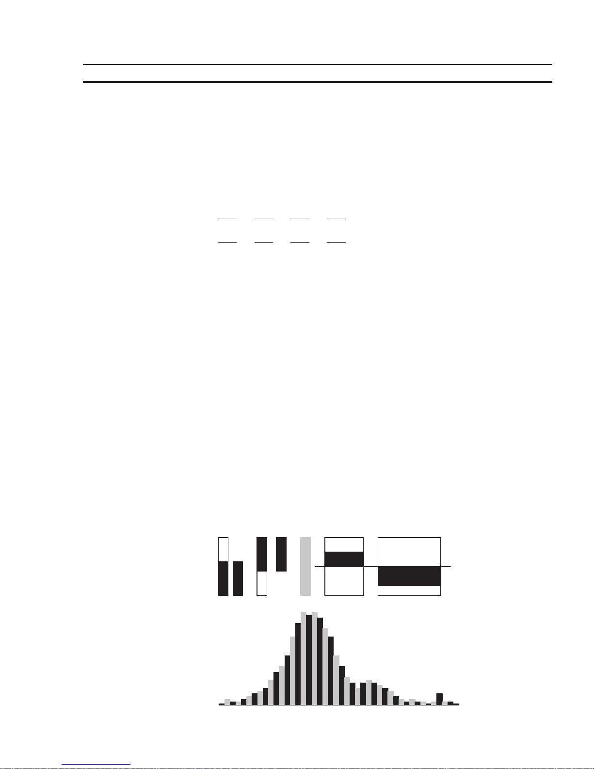
81
Standard Mode Section 4-6
4.6.1.7 ‘Binary Number’ Representation
The binary format permits the representation of single bits, bytes, words or Lwords.
The value for the ‘length’ entered in the variable definition corresponds to the number of bits to be represented. Counting always begins with bit 0. The number of
blanks indicates how many gaps (spaces) are inserted between each bit. Output is
always in the horizontal position. The direction of the positional significance can be
set in the variable definition.
Bit 3 Bit 2 Bit 1 Bit 0
0100Direction = 76543210
Bit 0 Bit 1 Bit 2 Bit 3
0010Direction = 01234567
0100 Blanks = 0
0100 Blanks = 1
0100 Blanks = 2
4.6.1.8 Bar Representation
Variables in I/O masks can be represented as bars. They can be programmed to be
either horizontal or vertical. The bars can start at a reference point (e.g. in the
center of the display) and extend in both the positive and the negative direction.
The range of values of the bars can be defined by specifying the upper and lower
limit (corner values). The bars are represented on the terminal with the aid of four
different graphical objects, the simplest of which is a fill pattern. Separate fill patterns can be specified for:
- the empty part of the bar
- the filled-in bar
- the ‘lower limit exceeded’ bar
- the ‘upper limit exceeded’ bar
The programming software includes seven default fill patterns for representing
bars on the operating terminal. The other, above-mentioned graphical objects can
also be used to design your own fill patterns and shapes.
Fig.5: Different forms of bar representation
Page 96

82
Standard Mode Section 4-6
Bar charts can be output once only, cyclically or after defined events (event-controlled). They are used purely to indicate actual values.
The range of values for outputs extends from -32768 to +32767.
If your mask contains several bars, you should address the variables such
that they can be transferred contiguously.
Each bar varies between a lower limit and an upper limit. Outside these limits, it
changes to the predefined fill pattern for Upper or Lower Limit Exceeded.
Possible applications:
- Vertical and horizontal trend displays
- Visualized monitoring of limit values
- Histograms
- Filling-level indications
Example of a filling-level indication:
Bitmap:
Lower Limit Exceeded
Intermediate V alueBitmap:
Lower Limit
Bitmap:
Upper Limit
Bitmap:
Upper Limit Exceeded
Fig. 6: Example of a filling-level indication
The bar mode of representation always means a slower output rate. Each bar
therefore always corresponds to an integer multiple of a character. The smallest
possible bar is equivalent in size to a single character, while the largest bar covers
the entire display. The bars ‘grow’ one pixel at a time.
4.6.1.9 Curve Representation (Trendline)
The curve mode of representation permits value tables to be output as dotted lines.
A ‘curve’ variable must be defined in a mask in order to represent a curve. The size
of the curve is determined by its length and height. If a coordinate system is required, it can be displayed with the aid of background images.
The address of the curve variable represents the start of a value table in the PLC.
Each value in the table describes one pixel on the curve. The graphical representation of the value table resembles that for cyclic output variables.
Examples of a variable time history:
- Output of one-time processes
- Memory function of a point recorder
- Filling-level curves
A curve is limited by the following parameters:
- Maximum height: Height of the display
- Maximum width: 54 pixels per curve variable
Page 97

83
Standard Mode Section 4-6
If you need a width of more than 54 pixels, you can output several curves directly
adjacent to one another.
Fig. 7: Example of a curve representation
The height information, in other words the variable values, is read from the controller in a contiguous field by means of one read job. The height information in the field
element with the starting address
(address + 0)
is displayed on the far left. All
subsequent height information (
address + n
) is shifted one pixel position to the
right. The curve height information is refreshed cyclically.
The output is thereby deleted and written again one pixel at a time.
Only two parameters are required to represent a curve:
- Curve width as a multiple of the character width (normal font)
- Curve height as a multiple of the character height (normal font)
4.6.2 Input Variables
Input variables, when displayed for the first time (when the mask is activated), are
treated in the same way as one-time output variables, i. e. the same representation
options are available. This includes the scaling effect.
Scaling is performed on the value in the PLC.
Input variables can be modified in the terminal by means of Editors. Their functionality is determined by the type of Editor that is selected.
The Editors that are supported for variable input are the same as those supported
for variable output. Editing of the variables is subject to certain conditions which
must take into consideration by the user when creating the project, such as the
password protection and the external data release, for example.
The following must be observed when entering timers and counters:
Timer
When writing to a timer variable, any scaling that may have been performed is first
reversed to give the time value to the base 10 ms again. The BCD-coded value is
then calculated so that the lowest possible time base is used.
Avoid writing to a timer word in the PLC, as this has uncontrolled results on
the control bits.
Page 98

84
Standard Mode Section 4-6
Counter
When writing to a counter variable, any scaling that may have been performed is
first reversed. The BCD-coded value is then computed and transferred to the PLC.
Avoid writing to a counter word in the PLC, as this has uncontrolled results
on the control bits.
Formula for Scaling Input Values
Input values transferred by the PLC are processed according to
formula 1
before
being displayed. After the values have been edited, they are processed in accordance with the inverse function (
formula 2
) before being transferred back to the PLC.
The inverse function will automatically be generated in the terminal. Operands
must be defined by the user on the basis of the values in the PLC including the input
value.
Input value × Summand
PLC value = × Divisor
Factor
Fig. 8: Formula 2
During conversion, the last digit is automatically rounded. This must be kept in mind
when defining the upper limit.
(Input value × Factor) , (Pos. Upper Limit - Divisor / 2)
Fig. 9: Formula 3
Plausibility Check
A plausibility check is performed on all input variables. As a part of this check, the
entered value is validated against the upper and lower limits specified in the variable definition. System messages are generated if the entered value is outside
these limits. In this case, the invalid value will not be transferred to the controller
and the previous (valid) value will be retained.
If the system message texts ‘Value too large’ and ‘Value too small’ are deleted, the
following applies:
- if the value drops below the limit, the value corresponding to the lower limit is
used
- if the value exceeds the upper limit, the value corresponding to the upper limit is
used.
A system message is not output during this process.
Help Text for Input Variables
A screen-sized help text can be created for each input variable. This help text can
be displayed in the Editor by pressing the Help key. Important information to be
inserted in a help text may include the upper and lower limits, the impact of variables on the process to be carried out, or any interactions with other variables.
If a variable-specific help text is not defined, the default help text will be displayed
instead. This is also a screen-sized text which can be edited in the programming
software. If a default help text is not defined, a blank mask will be displayed.
Page 99

85
Standard Mode Section 4-6
4.6.3 System Variables
System variables can be used to control terminal-internal functions.
System variables can be referenced to function keys and soft keys. They can also
be used in masks as normal variables for input and output processes.
The following applies if a system variable is linked to a function key or soft key:
- do not link a change of mask function and a system variable to the same key
- it is not necessary that the same function key or soft key is used to set (1) and
reset (0) a system variable
- jogging mode is obtained by using the same function key or soft key to set (1)
and reset (0) a system variable.
Do
not include the names of system variables in the variable list. If the name of a
system variable is referenced to a PLC address, it will loose its terminal-internal
function.
The following subchapters list the system variables, organized into separate
groups of functionality, and describes their functions.
4.6.3.1 Basic Functions
IntEraseEprom
Allows the user description to be erased from the Flash memory and prepares the
terminal for a new download via interface channel SER2. There will be no communication with any connected PLC during this process. Writing of a ‘1’ to this variable
erases the user description unconditionally. Subsequently, the variable is automatically reset to ‘0’.
Data type: Numeric
Editor: Selection text , positive decimal number
Output: --Possible values: (0) Inactive Initial state
(1) Active Erases the user description
MainVersion
Allows the user to display the current firmware version of the operating terminal.
Data type: Alphanumeric
Editor: --Output: Alphanumeric, 8 characters
Possible values: Format specified by manufacturer
ComVersion
Is used to display the type and version number of the current communication protocol.
Data type: Alphanumeric
Editor: --Output: Alphanumeric, 8 characters
Possible values: Format specified by manufacturer
Page 100

86
Standard Mode Section 4-6
UserVersion
Indicates the version number of the project description to the operator. The user
enters this number into the programming system during programming time.
Data type: Numeric
Editor: --Output: Numeric, 3 digits
Possible values: ---
Boot
This variable can be used to initiate the terminal to boot (system restart). The variable is suitable for integrating the setup function into the regular operator guidance,
making it possible to modify terminal parameters which require a subsequent reinitialization (system restart) in any I/O mask. The terminal is booted if a ‘1’ is written
to this variable. Subsequently, the variable is automatically reset to ‘0’.
Data type: Numeric
Editor: Selection text , positive decimal number
Output: --Possible values: (0) Inactive Initial state
(1) Active System restart
LCDContrast
Is used to adjust the contrast for terminals with liquid crystal displays.
Data type: Numeric
Editor: Integer
Output: --Possible values: -127 to +127 (to be limited further based on terminal
type)
LCDBackground
Is used to adjust the background of the display. This variable is only relevant for
operating terminals fitted with a corresponding display.
Data type: Numeric
Editor: Selection text , positive decimal number
Output: --Possible values: (0) Normal representation
(1) Inverse background
LCDBackLight
Is used to adjust the background lighting of the display. This variable is only relevant for operating terminals fitted with a corresponding display.
Data type: Numeric
Editor: Any
Output: --Possible values: (0) Background lighting OFF
(1 to x) Background lighting ON (dimmed)
 Loading...