

Page 1

Cat No. V029-E1-2
NT11S
Programmable Terminal
OPERATION MANUAL
Page 2

OMRON Corporation
PT Business Promotion Department
FA Division H.Q.
Yokohama Business Park
134. Godo-cho, Hodogaya-ku, Yokohama-shi
Kanagawa 240 Japan
Tel: (81) 45--336--6209/Fax: (81) 45--336--6239
Regional Headquarters
OMRON EUROPE B.V.
Wegalaan 69. NL-2132 JD Hoofddorp
The Netherlands
Tel: (31) 2503--81--300/Fax: (31) 2503--81--388
OMRON ELECTRONICS, INC.
1 East Commerce Drive, Schaumburg. IL 60173
U.S.A.
Tel: (1) 708--843--7900/Fax: (1) 708--843--8568
OMRON MANAGEMENT CENTRE OF ASIAPACIFIC PTE LTD.
510 Thomson Road #13--03
SLF Bldg.
1129 Singapore
Tel: (65) 353--2611/Fax: (65) 353--5391
Page 3

iiiiii
Page 4

Page 5

NT-series
Programmable Terminal
Operation Manual
Produced June 1997
Page 6

iv
Page 7

OMRON Product References
All OMRON products are capitalized inthis manual. The word“Unit” is alsocapitalizedwhen itreferstoan
OMRON product, regardless of whether or not it appears in the proper name of the product.
The abbreviation “Ch,” which appears in some displays and on some OMRON products, often means
“word” and is abbreviated “Wd” in documentation in this sense.
The abbreviation “PC” means Programmable Controller and is not used as an abbreviation for anything
else.
The abbreviation “Host” means PC that controls NT11S.
Visual Aids
The following headings appear in the left column of the manual to help you locate different types of information.
Note Indicates information of particular interest for efficient and convenient operation
of the product.
1, 2, 3... 1. Indicates lists of one sort or another, such as procedures, checklists, etc.
OMRON, 1997
All rights reserved. No part of this publication may be reproduced, stored in a retrieval system, or transmitted, in any
form, or by any means, mechanical, electronic, photocopying, recording, or otherwise, without the prior written permission of OMRON.
No patent liability is assumed with respect to the use of the information contained herein. Moreover, because OMRON
is constantly striving to improve its high-quality products, the information contained in this manual is subject to change
without notice. Every precaution has been taken in the preparation of this manual. Nevertheless, OMRON assumes no
responsibility for errors or omissions. Neither is any liability assumed for damages resulting from the use of the information contained in this publication.
v
Page 8

vi
Page 9

TABLE OF CONTENTS
PRECAUTIONS xi. . . . . . . . . . . . . . . . . . . . . . . . . . . . . . . . .
1 Intended Audience xii. . . . . . . . . . . . . . . . . . . . . . . . . . . . . . . . . . . . . . . . . . . . . . . . . . . . . . . . . . .
2 General Precautions xii. . . . . . . . . . . . . . . . . . . . . . . . . . . . . . . . . . . . . . . . . . . . . . . . . . . . . . . . . .
3 Safety Precautions xii. . . . . . . . . . . . . . . . . . . . . . . . . . . . . . . . . . . . . . . . . . . . . . . . . . . . . . . . . . .
SECTION 1
Functions of the NT11S 1. . . . . . . . . . . . . . . . . . . . . . . . . . . .
1-1 Getting Starting 2. . . . . . . . . . . . . . . . . . . . . . . . . . . . . . . . . . . . . . . . . . . . . . . . . . . . . . . .
1-2 Role and Operation of NT11S 3. . . . . . . . . . . . . . . . . . . . . . . . . . . . . . . . . . . . . . . . . . . . .
1-3 Functions of NT11S 5. . . . . . . . . . . . . . . . . . . . . . . . . . . . . . . . . . . . . . . . . . . . . . . . . . . . .
1-4 System Configuration 9. . . . . . . . . . . . . . . . . . . . . . . . . . . . . . . . . . . . . . . . . . . . . . . . . . .
1-5 Direct Connection Function 10. . . . . . . . . . . . . . . . . . . . . . . . . . . . . . . . . . . . . . . . . . . . . . .
1-6 Before Operating 15. . . . . . . . . . . . . . . . . . . . . . . . . . . . . . . . . . . . . . . . . . . . . . . . . . . . . . .
SECTION 2
Hardware Settings and Connections 17. . . . . . . . . . . . . . . . .
2-1 Description of Parts and Settings 18. . . . . . . . . . . . . . . . . . . . . . . . . . . . . . . . . . . . . . . . . . .
2-2 Installation 22. . . . . . . . . . . . . . . . . . . . . . . . . . . . . . . . . . . . . . . . . . . . . . . . . . . . . . . . . . . .
2-3 Connecting to the Support Tool 25. . . . . . . . . . . . . . . . . . . . . . . . . . . . . . . . . . . . . . . . . . . .
2-4 Connection to a PC by the Host Link (RS-232C Type) 26. . . . . . . . . . . . . . . . . . . . . . . . .
2-5 Connection to a PC by the Host Link (RS-422A Type) 31. . . . . . . . . . . . . . . . . . . . . . . . .
2-6 Connection to a PC by the NT Link 37. . . . . . . . . . . . . . . . . . . . . . . . . . . . . . . . . . . . . . . .
2-7 Connecting a Printer 39. . . . . . . . . . . . . . . . . . . . . . . . . . . . . . . . . . . . . . . . . . . . . . . . . . . .
SECTION 3
System Menu Operation 41. . . . . . . . . . . . . . . . . . . . . . . . . . .
3-1 Operation Flow by the System Menu 42. . . . . . . . . . . . . . . . . . . . . . . . . . . . . . . . . . . . . . .
3-2 Starting the NT11S 43. . . . . . . . . . . . . . . . . . . . . . . . . . . . . . . . . . . . . . . . . . . . . . . . . . . . .
3-3 Operation Modes and the System Menu 44. . . . . . . . . . . . . . . . . . . . . . . . . . . . . . . . . . . . .
3-4 Initializing Memory 48. . . . . . . . . . . . . . . . . . . . . . . . . . . . . . . . . . . . . . . . . . . . . . . . . . . . .
3-5 Transferring the System Program 51. . . . . . . . . . . . . . . . . . . . . . . . . . . . . . . . . . . . . . . . . .
3-6 Registering the Screen Data 54. . . . . . . . . . . . . . . . . . . . . . . . . . . . . . . . . . . . . . . . . . . . . .
3-7 Setting the Conditions of Communications with the PC
by Using the Memory Switches 57. . . . . . . . . . . . . . . . . . . . . . . . . . . . . . . . . . . . . . . . . . . .
3-8 Starting the Operation 62. . . . . . . . . . . . . . . . . . . . . . . . . . . . . . . . . . . . . . . . . . . . . . . . . . .
3-9 Backlight OFF 63. . . . . . . . . . . . . . . . . . . . . . . . . . . . . . . . . . . . . . . . . . . . . . . . . . . . . . . . .
3-10 System Maintenance 65. . . . . . . . . . . . . . . . . . . . . . . . . . . . . . . . . . . . . . . . . . . . . . . . . . . .
SECTION 4
NT11S Functions 71. . . . . . . . . . . . . . . . . . . . . . . . . . . . . . . . .
4-1 Creating and Transmitting Screen Data 72. . . . . . . . . . . . . . . . . . . . . . . . . . . . . . . . . . . . .
4-2 Outline of Functions 77. . . . . . . . . . . . . . . . . . . . . . . . . . . . . . . . . . . . . . . . . . . . . . . . . . . .
4-3 Screen Display 80. . . . . . . . . . . . . . . . . . . . . . . . . . . . . . . . . . . . . . . . . . . . . . . . . . . . . . . . .
4-4 Memory Tables 81. . . . . . . . . . . . . . . . . . . . . . . . . . . . . . . . . . . . . . . . . . . . . . . . . . . . . . . .
4-5 Bar Graphs 83. . . . . . . . . . . . . . . . . . . . . . . . . . . . . . . . . . . . . . . . . . . . . . . . . . . . . . . . . . . .
4-6 Numeral Setting 85. . . . . . . . . . . . . . . . . . . . . . . . . . . . . . . . . . . . . . . . . . . . . . . . . . . . . . . .
4-7 Menu Screen Function 87. . . . . . . . . . . . . . . . . . . . . . . . . . . . . . . . . . . . . . . . . . . . . . . . . . .
4-8 Password Screen Display Function 88. . . . . . . . . . . . . . . . . . . . . . . . . . . . . . . . . . . . . . . . .
4-9 Display History Screen Function 90. . . . . . . . . . . . . . . . . . . . . . . . . . . . . . . . . . . . . . . . . . .
vii
Page 10

4-10 Daily Report/Display History Printing Function 91. . . . . . . . . . . . . . . . . . . . . . . . . . . . . . .
SECTION 5
Using Host Link/NT Link 95. . . . . . . . . . . . . . . . . . . . . . . . . .
5-1 Outline of Host Link / NT Link Operation 96. . . . . . . . . . . . . . . . . . . . . . . . . . . . . . . . . . .
5-2 Memory Tables and Bar Graph 106. . . . . . . . . . . . . . . . . . . . . . . . . . . . . . . . . . . . . . . . . . . .
5-3 Numeral Setting 119. . . . . . . . . . . . . . . . . . . . . . . . . . . . . . . . . . . . . . . . . . . . . . . . . . . . . . . .
5-4 NT11S Status Control 122. . . . . . . . . . . . . . . . . . . . . . . . . . . . . . . . . . . . . . . . . . . . . . . . . . .
5-5 Notification of the Operating Status to the PC
(Determining the NT11S Operating Status) 126. . . . . . . . . . . . . . . . . . . . . . . . . . . . . . . . . .
SECTION 6
Troubleshooting and Maintenance 131. . . . . . . . . . . . . . . . . . .
6-1 Hardware Faults 132. . . . . . . . . . . . . . . . . . . . . . . . . . . . . . . . . . . . . . . . . . . . . . . . . . . . . . . .
6-2 Responding to Displayed Error Messages 133. . . . . . . . . . . . . . . . . . . . . . . . . . . . . . . . . . . .
6-3 Inspection and Cleaning 137. . . . . . . . . . . . . . . . . . . . . . . . . . . . . . . . . . . . . . . . . . . . . . . . .
APPENDICES 139. . . . . . . . . . . . . . . . . . . . . . . . . . . . . . . . . . .
A. Specifications 139. . . . . . . . . . . . . . . . . . . . . . . . . . . . . . . . . . . . . . . . . . . . . . . . . . . . . . . . . . . .
B. Dimensions 144. . . . . . . . . . . . . . . . . . . . . . . . . . . . . . . . . . . . . . . . . . . . . . . . . . . . . . . . . . . . . .
C. NT11S Installation Environment 145. . . . . . . . . . . . . . . . . . . . . . . . . . . . . . . . . . . . . . . . . . . . .
D. Method for Making the Cable for Connection to the PC 146. . . . . . . . . . . . . . . . . . . . . . . . . .
E. Making the Cable for Connection to the Support Tool 155. . . . . . . . . . . . . . . . . . . . . . . . . . . .
F. NT11S Internal Processing 156. . . . . . . . . . . . . . . . . . . . . . . . . . . . . . . . . . . . . . . . . . . . . . . . . .
G. Model List 158. . . . . . . . . . . . . . . . . . . . . . . . . . . . . . . . . . . . . . . . . . . . . . . . . . . . . . . . . . . . . .
H. PC Memory Map 160. . . . . . . . . . . . . . . . . . . . . . . . . . . . . . . . . . . . . . . . . . . . . . . . . . . . . . . . .
I. Special Characters 161. . . . . . . . . . . . . . . . . . . . . . . . . . . . . . . . . . . . . . . . . . . . . . . . . . . . . . . .
INDEX 163. . . . . . . . . . . . . . . . . . . . . . . . . . . . . . . . . . . . . . . . .
viii
Page 11

About this Manual:
This manual describes the basicfunctions and operation proceduresof the NT-seriesprogrammable terminal NT11S, its operations when connected to a PC, and includes the sections described below.
Please readthismanualcarefully andbe sureyouunderstand the information provided beforeattempting
to install and operate the NT-series programmable terminal NT11S.
Section 1 describes the operation functions, system configuration, and the direct connection function of
the NT11S.
Section 2 describes the hardware settings, installation to an operation panel, connection to optional devices and PC.
Section 3 describes the operation of the System Menu and the maintenance of the NT11S.
Section 4 describes the functions of the NT11S when it is connected to a PC.
Section 5 describes how to use the NT11S when it is connected to the PC using the host link or NT link.
Section 6 describes the procedures to follow when the NT11S does not operate correctly.
APPENDIX describes the specifications and the method for making connecting cables, and includes an
area list for the PC.
ix
Page 12

Related Manuals and Their Contents:
The related manuals are listed below.
The j symbol at the end of the manual number is the revision history symbol.
[Operating the programmable terminal and communicating with the host]
S NT11S Programmable Terminal Operation Manual (V029-E1-j)
This operation manual is the manual for the NT11S itself.
The NT11Sisa unit which integrates a programmable terminal body. This opera-
tion manual describes the functions and handling of the programmable terminal
body.
[Creating and transferring screen data]
S NT-series NT11S Support Tool Operation Manual (V030-E1-j)
The screens displayed on the NT11S are created with the support tool andtrans-
ferred to the NT11S. This manual describes how to create and transfer screen
data.
This manual. . . . . . . . . . . . . . . . . . . . . . . . . . . . . . . . . . . . . . . . . . . . . . . . . . . . . . .
x
Page 13

PRECAUTIONS
This section provides general precautions for using the Programmable Terminal.
The information contained in this section is important for the safe and reliable application of the Programmable
Terminal. You must read this section and understand the information contained before attempting to set up or operate a Programmable Terminal.
1 Intended Audience xii. . . . . . . . . . . . . . . . . . . . . . . . . . . . . . . . . . . . . . . . . . . . . . . . . . . . . . . . . . .
2 General Precautions xii. . . . . . . . . . . . . . . . . . . . . . . . . . . . . . . . . . . . . . . . . . . . . . . . . . . . . . . . . .
3 Safety Precautions xii. . . . . . . . . . . . . . . . . . . . . . . . . . . . . . . . . . . . . . . . . . . . . . . . . . . . . . . . . . . .
xi
Page 14

Safety Precautions
1 Intended Audience
This manual is intended for the following personnel, who must also have knowledge of electrical systems (an electrical engineer or the equivalent).
S Personnel in charge of installing FA systems.
S Personnel in charge of designing FA systems.
S Personnel in charge of managing FA systems and facilities.
2 General Precautions
The user must operate the product according to the performance specifications
described in the operation manuals.
Before usingthe product under conditions which arenot desctibed in the manual
or applying the product to nuclear control systems, railroad systems, aviation
systems, vehicles, combustion systems, medical equipment, amusement machines, safety equipment, and other systems, machines, and equipment that
may have a serious influence on lives and property if used improperly, consult
your OMRON representative.
Make sure that the ratings and performance characteristics of the product are
sufficient for the systems, machines, and equipment, and be sure to provide the
systems, machines, and equipment with double safety mechanisms.
This manual provides information forusingthe Programmable Terminal. Be sure
to read this manual before attempting to use the software and keep this manual
close at hand for reference during operation.
WARNING It is extremely important that Programmable Terminals and related devices be
used for the specified purpose and under the specified conditions, especially in
applications that can directly orindirectlyaffect human life. You must consultwith
your OMRON representative before applying Programmable Terminals to the
abovementioned applications.
WARNING Donot useinput functions suchas PT touch switches for applications wheredan-
ger to humanlifeorserious damageis possible,or for emergency switchapplications.
3 Safety Precautions
Read thesesafetyprecautions carefullyand makesure youunderstand thembefore using the Programmable Terminal so that you canuse it safely andcorrectly.
Safety Conventions and This operation manual uses the following conventions and symbols to indicate
their Meanings cautions, warnings, and dangers in order to ensure safe use of the PT. The cau-
tions, warnings, and dangers shown here contain important information related
to safety. The instructions in these cautions, warnings, and dangers must be
observed.
The conventions used and their meanings are presented below.
DANGER! Indicates information that, if not heeded, is likely to result in loss of life orserious
injury.
WARNING Indicates information that, if not heeded, could possibly result in loss of life or se-
rious injury.
xii
CAUTION Indicates information that,ifnot heeded,could resultin relativelyserious orminor
injury, damage to the product, or faulty operation.
Page 15

CAUTION S Do notuse inputfunctions suchas PTfunction keysfor applications wheredan-
ger to human life or serious property damage is possible, or as the emergency
stop switch.
S On unpacking the unit, check its external appearanceand confirm that there is
no damage. Also confirm that there is no abnormal noise on shaking the unit
lightly. The product may malfunction if it is damaged.
S The thickness of applicable operation panel is 1.6 mm to 4.8 mm. All futtings
must be tightened uniformly to a torque of 0.5 to 0.6 N m in order to ensure
water- anddust-resistence. The panelmustnot be soiledorwarped, andmust
be able to support an installation that will remain secure and strong.
S During work at the panel, take care to ensure that no metal scraps enter the
unit. Otherwise, the product may malfunction.
S Carefully check the wiring before switching ON the power.
S Do not connect AC power to the DC terminals.
S Use DC power supplies with low voltage and frequency fluctuations.
S For the connection to the power supply terminal block, twisted wires of 2 mm
or greater cross sectional area and M 3.5 size crimp terminals must be used.
Tighten the screws on the terminal block to a torque of 0.5 N m.
Otherwise fire may occur.
S After connecting a communication cable, always secure it with the screws.
Otherwise the cable may disconnect, causing operation to fail.
S The cable’s tensile load is 30 N. Do not subject it to loads greater than this.
Otherwise a discontinuity may occur, causing operation to fail.
S Switch off the NT11S power supply before connecting or disconnecting a con-
nector.
S If the connection cable is connected or disconnected while the power of the
printer ison,the NT11S may malfunction. Make suretoturnoff thepowerof the
printer before connecting or disconnecting the connection cable.
S In addition to the DIP switches, set also the “Comm. Method”, “Host Link
Speed”, “Auto-restart”, etc.at thememoryswitches. Forthese settings,referto
Section 3-7 “Setting the Conditions of Communications with the PC by Using
the Memory Switches” (page 57)
S After changing the switch settings, always press the reset switch or turn the
power off and back on.
Otherwise the system will not operate as expected.
2
S Confirm system safety before turning the power ON/OFF or resetting.
Otherwise the system may operate unpredictably.
S Carefully check the operation of all screen data and host programs before us-
ing them. If incorrect, the system may operate unpredictably.
Otherwise the system may operate unpredictably.
S After images may remain if the same pattern is displayed for a long period.
To prevent the formation of an afterimage, either use the screen saver function
or periodicaly switch screens.
xiii
Page 16

S Do not disassemble for repairs or modification. Otherwise, the product may
malfunction.
S The disposal of the unit may be regulated by nationl or local authorities. Dis-
pose of them in accordance with the laws and regulations ofthe relevant country and local authority.
S Set so that there is no overlap between the PT status control area and PT sta-
tus notify area. Otherwise the system may operate unpredictably.
xiv
Page 17

SECTION 1
Functions of the NT11S
NT11Sis anew programmable terminal (PT)which incorporates a host interface unit in a programmable terminal body. It can
be easily installed and used.
This section gives the operation examples and characteristics of the NT11S sothat you will understand the applications of the
NT11S.
1-1 Getting Starting 2. . . . . . . . . . . . . . . . . . . . . . . . . . . . . . . . . . . . . . . . . . . . . . . . . . . . . . . . . . . . . .
1-2 Role and Operation of NT11S 3. . . . . . . . . . . . . . . . . . . . . . . . . . . . . . . . . . . . . . . . . . . . . . . . . . .
1-2-1 Operations of NT11S 4. . . . . . . . . . . . . . . . . . . . . . . . . . . . . . . . . . . . . . . . . . . . . . . . . . . .
1-3 Functions of NT11S 5. . . . . . . . . . . . . . . . . . . . . . . . . . . . . . . . . . . . . . . . . . . . . . . . . . . . . . . . . .
1-3-1 Features 5. . . . . . . . . . . . . . . . . . . . . . . . . . . . . . . . . . . . . . . . . . . . . . . . . . . . . . . . . . . . . .
1-3-2 Principal Functions of NT11S 6. . . . . . . . . . . . . . . . . . . . . . . . . . . . . . . . . . . . . . . . . . . . .
1-3-3 Displays 7. . . . . . . . . . . . . . . . . . . . . . . . . . . . . . . . . . . . . . . . . . . . . . . . . . . . . . . . . . . . . .
1-3-4 System Keys 8. . . . . . . . . . . . . . . . . . . . . . . . . . . . . . . . . . . . . . . . . . . . . . . . . . . . . . . . . . .
1-4 System Configuration 9. . . . . . . . . . . . . . . . . . . . . . . . . . . . . . . . . . . . . . . . . . . . . . . . . . . . . . . . .
1-5 Direct Connection Function 10. . . . . . . . . . . . . . . . . . . . . . . . . . . . . . . . . . . . . . . . . . . . . . . . . . . .
1-5-1 NT Link 11. . . . . . . . . . . . . . . . . . . . . . . . . . . . . . . . . . . . . . . . . . . . . . . . . . . . . . . . . . . . . .
1-5-2 Functions of the Allocated Bits and Words 12. . . . . . . . . . . . . . . . . . . . . . . . . . . . . . . . . . .
1-6 Before Operating 15. . . . . . . . . . . . . . . . . . . . . . . . . . . . . . . . . . . . . . . . . . . . . . . . . . . . . . . . . . . . .
1
Page 18

Getting Starting
Section 1-1
1-1 Getting Starting
To ensure that the NT11S works correctly, carefully observe the following when
installing and handling it.
Location Do not install the NT11S in a location subject to the following conditions;
S Near a computer, radio transmitter or receiver, etc.
S Dust, chemicals, or steam
S Severe temperature fluctuations
S High humidity and condensation
S Strong electrical or magnetic fields
S Poor ventilation
S Severe vibration
Handling Do not;
S Subject the NT11S to strong shocks or vibrations
S Put heavy objects on the NT11S
S Supply a voltage different from the specified voltage
S Disassemble or modify the NT11S
Cautions on Cleaning To clean the front panel, use a soft, dry cloth. If it is very dirty, use diluted (2%)
neutral detergent.
Do not use volatile solvents such as benzene, thinner, or a chemically treated
cloth. Their use will cause deformation or discoloration.
Cautions on Afterimage If the same screencontents are kept displayedfor a long time, an afterimage may
occur. To prevent this problem, either set the afterimage prevention function or
make a program which periodically changes the displayed screen.
Cautions on Operating the System Keys
Do not operate the system keys with sharply pointed objects, such as your fingernails or a screwdriver.
This could break the film.
2
Page 19
Role and Operation of NT11S
Section 1-2
1-2 Role and Operation of NT11S
NT11Sisa programmable terminal usedto display and transmit the information in
an FA site. The following gives a general description of the role and operation of
the NT11S for those who use a programmable terminal (PT) for the first time.
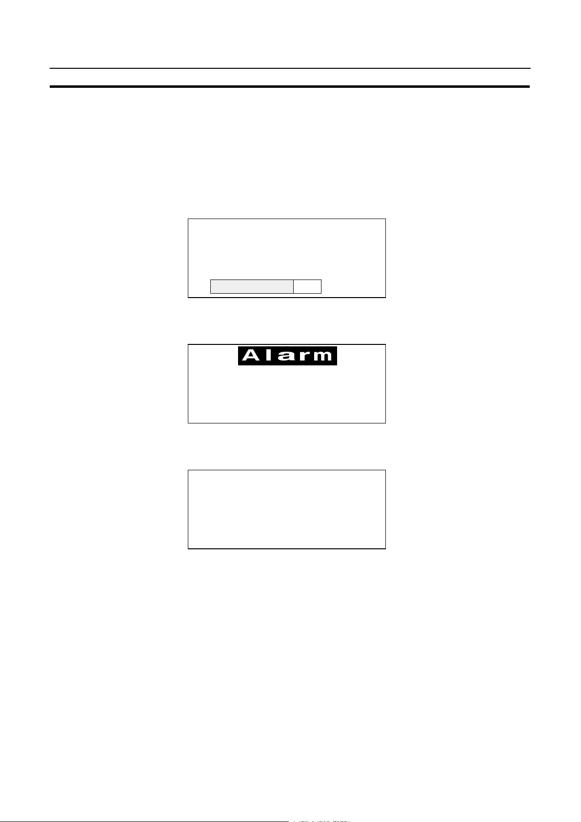
Production Line Status Monitoring
The NT11S displays real-time information about the system and equipment operating status, etc.
Line 1 Status
Machine:NT11S-ST121
Product: 137 units
75%
Messages The NT11S warns of system or equipment failures and prompts the appropriate
remedial action.
Assembly line B
Positioning pin
Panel Switch Functions The NT11S can be used in place of external data input equipment such as an op-
eration panel, to transmit data to a PC.
Positioning
X-AXIS 100 point
Y-AXIS 150 point
Z-AXIS 80 point
3
Page 20
Role and Operation of NT11S
Section 1-2
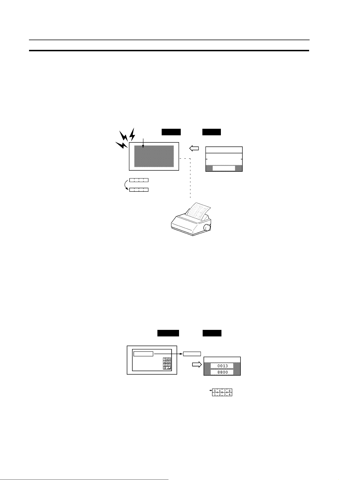
1-2-1 Operations of NT11S
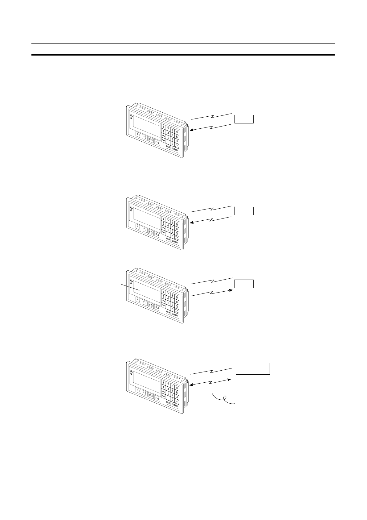
Displays Screens The information to be displayed (screen data) can be created on a computer by
using support tools and stored in the NT11S. The screen data can be displayedon
the NT11S in response to the instructions from a PC or system keys operation.
PC
The screen data designated by
instructions from PC or System
keys operation is displayed.
Receives Data from a PC
NT11S can be connected to a PC by a host link or NT link and receive necessary
data from the PC.
Host link, NT link
PC
OMRON’s PC
Sends Data to a PC Data input through a numeric key can be sent to a PC.
Numeric key
ON/OFF information,
numeric data, etc.
PC
Screen Data The screen data to be displayed on the NT11S can be created by a computer by
using supporttools.Connect the NT11S to aPC/AT with an RS-232C cablesothat
the screen data are transferred to the NT11S.
Create screen data.
RS-232C
Screen data
PC/AT
(support tools)
This connection is made only to
transmit the screen data by using
NT11S and tools.
4
Page 21
Functions of NT11S
Section 1-3
1-3 Functions of NT11S
The NT11S has the following features and functions;
1-3-1 Features
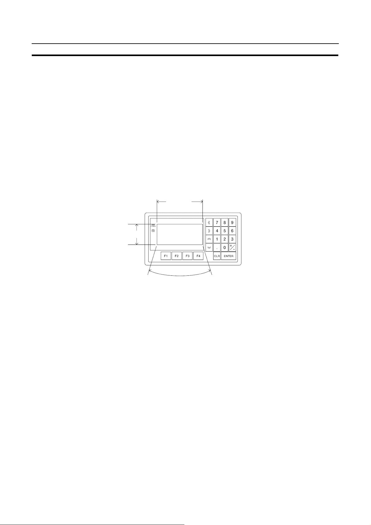
Downsized Body S The NT11S has the thinnest depth (31 mm or lessin the panel) in the NT series.
S It is very compact, with a width of 218 mm and a height of 113 mm.
S Features three ports: for RS-232C, RS-422A, and printer output.
S The tool connectors and the PC communication connectors are used in com-
mon.
Construction Best Suited to the FA Environment
S Easy-to-read screen even in direct sunlight.
S Waterproofed to a standard equivalent to IP65 and NEMA4.
160 dots
64 dots
Wide angle of visibility 35_
A Host I/F Unit, Screen Data Memory, and a system program transfer ROM are All Incorporated
S There is no complicated installation work except a simple connection to a PC.
S A flash memory is usedforthescreendata memory. There is no need of backup
battery.
S A host link (direct), and an NT link are standard equipment.
5
Page 22
Functions of NT11S
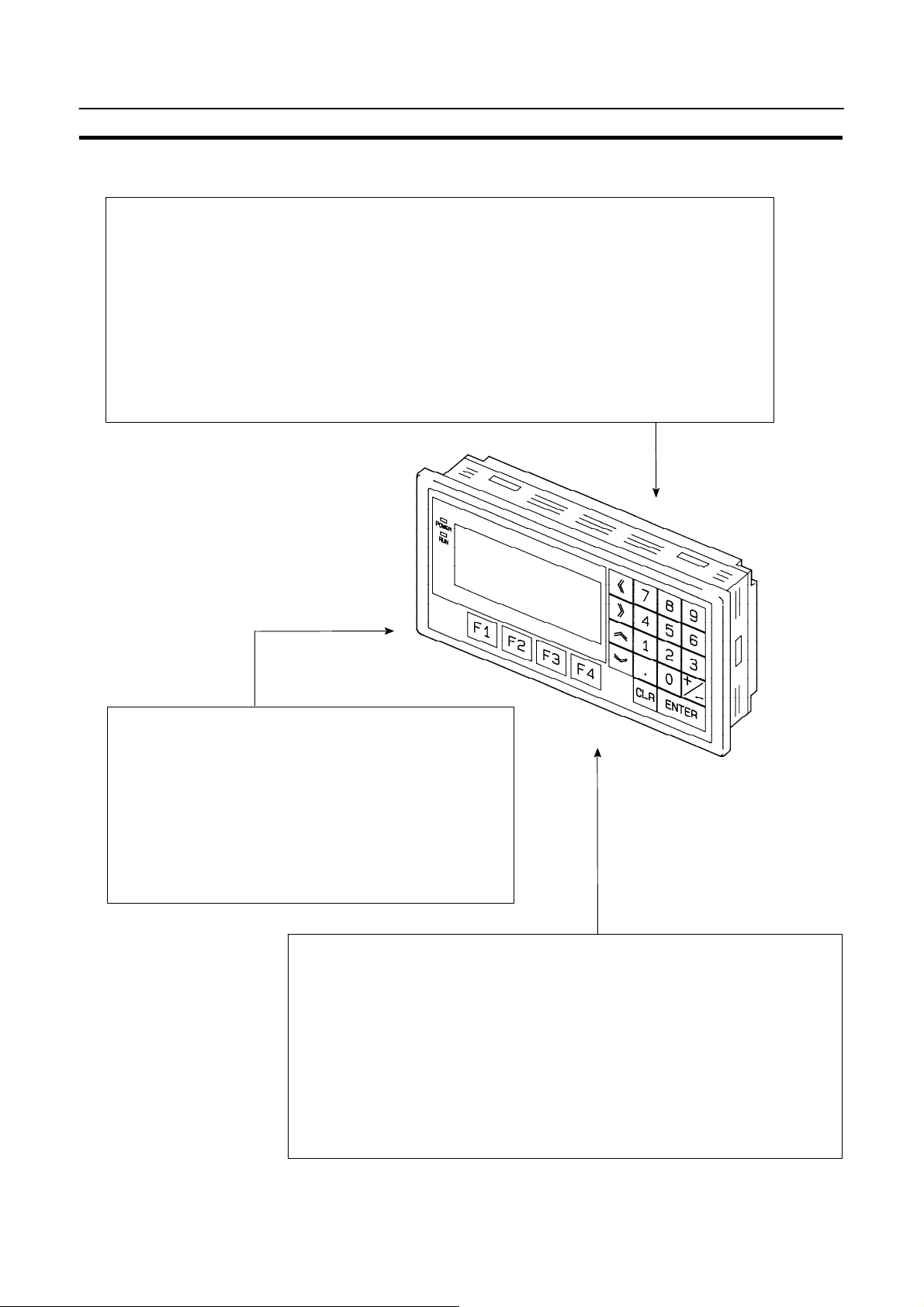
1-3-2 Principal Functions of NT11S
Functions Related to the Data Display
S Character display
Characters of standard and double-width can be displayed. Characters can flash or be highlighted.
S Memory data display
Contents of thecharacter-string memory table and the numeral memory table can bedisplayed.
The memory table contents can be changed from the PC.
S Bar graph display
Bar graphs corresponding to the contents of the numeral table can be displayed.
Section 1-3
Functions Related to the Data Input
S Input by the system key
Data can be input, and the displayed screen changed,
by using the numeric keys, function keys, and arrow
keys on the panel of the NT11S.
S Numeric setting function
The numeric valuescan beinput atthe operation siteby
the system key and sent to the PC.
Other Functions
S Communications with a PC
The host link, NT link is used to connect to a PC for data communication.
S System function
The system setting and maintenance can be executed by using the System
Menu on the screen.
S Screen data creation
The screen data can be created by using support tools on the computer and
stored in the unit.
6
Page 23

Functions of NT11S
1-3-3 Displays
Section 1-3
The NT11S can display elements such as characters, numeric value, and bar
graphs on ascreen.The screendatadisplayedon theNT11S are created byusing
support tools on a computer.
Characters
(character string)
Characters (text)
Bar graph
Characters (text) Characters and marks which do not need to be changed can be written directly to
the screen.
Characters (character-string memory table)
Character-strings stored in the character-string memory table are displayed. The
display characters can be changed by changing the data stored in the characterstring memory table.
Numeric Values (numeral memory tables)
Numbers stored in the numeral memory table are displayed. The display numbers
can be changed by changing the data stored in the numeral table. Hexadecimal
values can also be displayed.
Bar Graphs The bar graph extends and contracts in proportion to the data storedinthe numer-
al memory table. A percentage value can also be displayed simultaneously.
Marks Marks can be designed, created, and handled like characters by the user.
Line 1 Status
Machine:NT11S-ST121
Product:137 units
75%
Numeric value
(Numeral table)
7
Page 24
Functions of NT11S
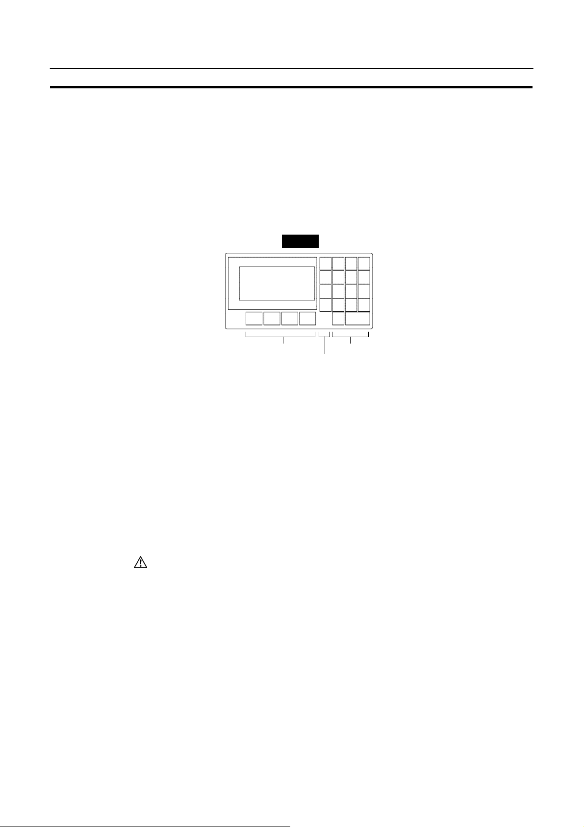
1-3-4 System Keys
Section 1-3
The NT11S has system keys on its panel for input functions.
The system keys are used for inputting numerical values and for notifications to
the PC.
The system keys can be classified into the three types shown below.
- Numeric keys
- Arrow keys
- Function keys
NT11S
Screen display
Caution
Function keys
Arrow keys
Numeric keys
S Numeric keys
These are the numeral keys from [0] to [9], the decimal point key [.], the sign key
[+/--], the [CLR] key and the [ENTER] key. These keys are used for inputting numerical values.
S Arrow keys
Used to select the required numerical value input field when there is more than
one on the screen.
S Function keys
Used for notifications from the NT11S to the PC.
Also used to switch between the RUN mode and the system menu when the
power is switched on.
Do notuseinput functionssuch asPT functionkeysfor applications wheredanger
to human life or serious property damage is possible, or as the emergency stop
switch.
8
Page 25
System Configuration
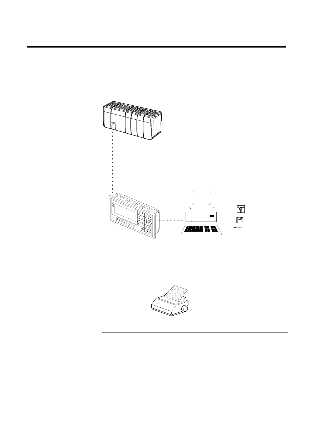
1-4 System Configuration
This section gives the basicconfiguration of asystem which uses an NT11S. Use
an RS-232C cable to connect to a PC. Refer to the manual for individualdevicefor
information on the equipment other than the NT11S in the system.
RS-232C cable
(for host link)
(Max. 15 m)
or RS-422A cable
(for host link)
(Max. 500 m)
Section 1-4
OMRON’s PC
Controls NT11S as required while controlling machines and
monitoring the production line.
Host link: CQM1, C200H(S) series PC
NT link: CQM1, C200H(S) series PC
CQM1, C200HS series: NT11S can be connected
directly to the CPU unit.
Note that C200H requires a host link unit.
CQM1 can be used with CPU41/42/43/44-E.
C200HS can be used with CPU21/23/31/33-E.
Reference
Support tool
NT11S
Gives displays of production line
monitoring and instructions to the
operation site and notifies the
switch ON/OFF status and
numeric value inputs to the PC.
Computer (support tool)
Connected to NT11S as required and used to transfer the
NT11S screens and make settings for the NT11S.
Computer: IBM PC/AT or compatible (IBM PC DOS Ver.5 or
Support tool: NT11S support tool type NT11S-ZA3AT-EV1
later)
Printer
Prints daily reports and
display histories.
Printer: ESC/P compatible
The following twocommunication methods aresupportedfor communicationsbetween the NT11S andPC: host link,and NTlink. Forthesetting procedure,referto
Section 3-7 Setting the Conditions of Communications with the PC by Using the
Memory Switches (page57).It isimpossible toconnecta personalcomputer used
to drive the support tool and a PC at the same time.
9
Page 26
Direct Connection Function
1-5 Direct Connection Function
The communication method applied between the NT11S and the PC is either a
host link or NT link.
The NT11Scanbe used to refer to the contents necessary for the displayinformation or to allocate the bits and words used for storing the input data to any area in
the PC. TheNT11S candirectlywriteand readsuch allocated bits andwords soas
to change the display elements, control the operating status, andnotify the status.
This function iscalled the “direct connection function”. The NT11S is designed exclusively for use with the direct connection.
The bits andwords allocated by thedirect connectionfunctionare called“allocated
bit” and “allocated word” respectively.
This function allowsto read the information to be displayed on the NT11S from the
memory area in the PC and to write it to the memory table in the NT11S. Also, the
data input on the NT11S can be written to the PC’s memory area. The NT11S
screen status can be switched according to the PC’s memory area, and the
NT11S’s status data can be written to the PC’s memory area.
NT11S PC
Section 1-5
Data memory area Internal relay area
Features of the Direct Connection Function
S The bits andwordsreferring to operatingstatus andwork instructioninformation
and those for storing input data can be freely allocated to almost any part of the
PC memory. Bits andwords inthe PCcan bereferenced fromany memorytable.
S The NT11S can directly refer to PC bit and word data sothat it canbeconnected
to a PC without changing the PC program which controls currently running production line.
S The area to control and notify the NT11S status, including display screens, ON/
OFF of the backlight, and printing of daily reports and display histories, can be
freely allocated to any part of the PC memory.
The direct connection function allows the NT11S to directly read and write almost
all bitsandwords in thePCand toautomatically changethe NT11S screendisplay.
This function canreduce the load on the PC sothat the program development efficiency of the PC improves.
Auxiliary relay area
Timer/counter
10
Page 27

Direct Connection Function
1-5-1 NT Link
Features of the NT Link
Section 1-5
The NT link is a new communication method applied between the NT11S and a
PC.
The NT link uses the direct connection function andcan execute high speedcommunications with a CPU (built-in NT link) of the CQM1, and C200HS.
S High speed communications with specific types of PCs can be executed.
S Writing in units of bits to the PC memory area is possible. (*)
S This can be used even when the PC is in the RUN mode.
(*) Except a DM area.
The NT link is compatible with the host link. The NT11S screen data and the PC
programs handled by the host link direct connection can be used with for the NT
link as they are.
11
Page 28

Direct Connection Function
1-5-2 Functions of the Allocated Bits and Words
Elements displayed on the NT11S and the NT11S status can be allocated to the
bits and words of the PC. By changing the contents of the bits and words, the
NT11S can be controlled by the PC. It is also possible to send data to the PC by
pressing the function keys on the panel of the NT11S.
S Controlling the NT11S by a PC
The following NT11S functions can be controlled by a PC.
Screens : Display of designated screens, confirmation of screen num-
bers, etc.
Memory tables : Writing to a memory table, copying from a memory table to
another memory table, etc.
System control : ON/OFF of backlight, control of output of daily reports and
display histories at a printer.
S Notifying from the NT11S to a PC
Data in the NT11S is sent to a PC when a numerickey is pressed. Thefollowing
types of data are sent to a PC.
- NT11S status
Section 1-5
- Password input status
- Numeric values input by the numeral keys
- Function key input status
12
Page 29
Direct Connection Function
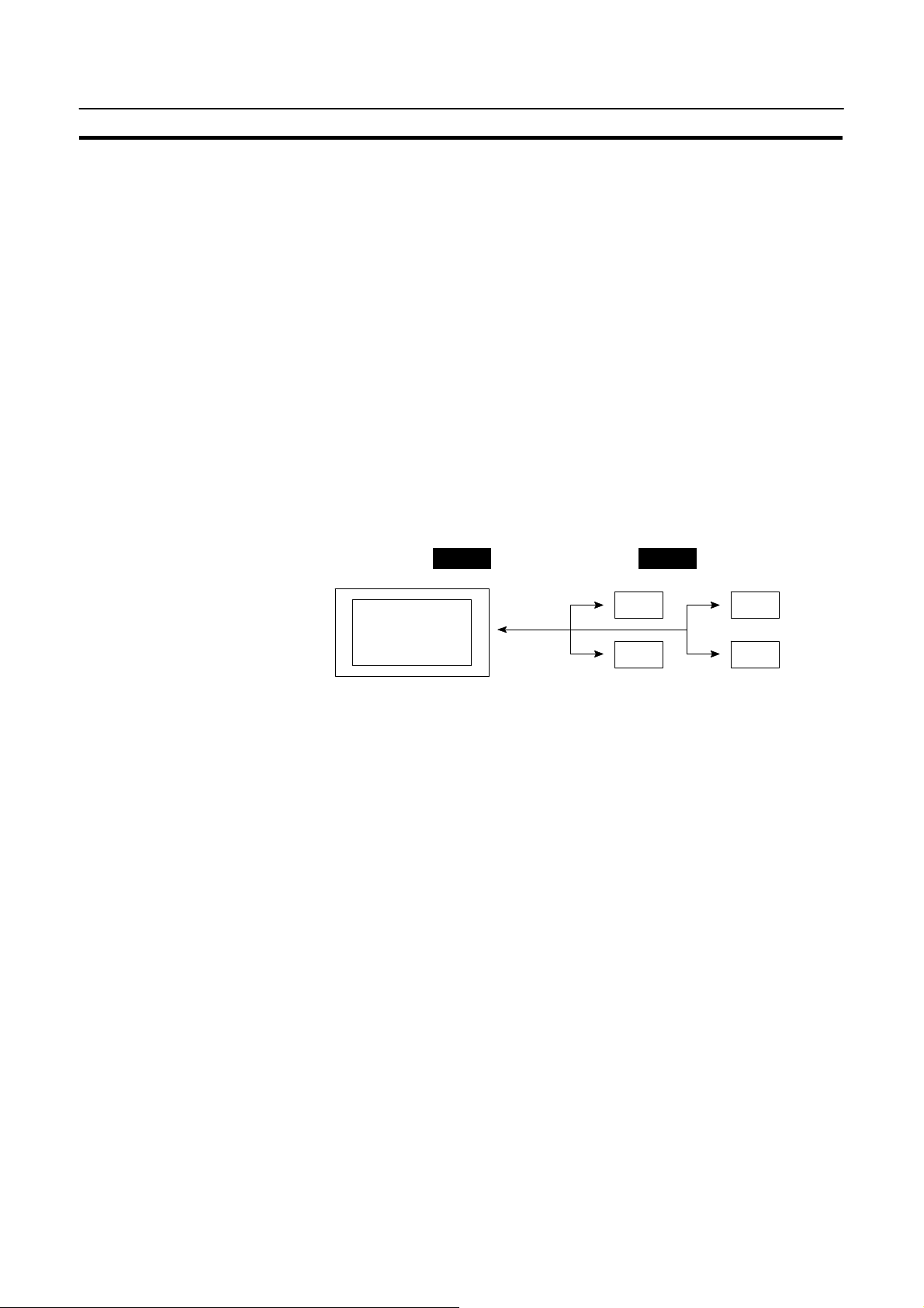
Functions of Display Elements
Section 1-5
S Numeral memory table
Allocation destination: Word
Numeral memory
table 1 (TIM003)
Numeral memory table 150 (0005CH)
NT11S
Allocate numeral memory tables to arbitrary words in the PC. If word contents
change when corresponding numeral memory table is displayed on the screen,
the value on the screen will also change. Monitoring of words can also be made
easily.
Reading and writing are executed so that the contents of allocated words are
always the same as those of the numeral memory tables.
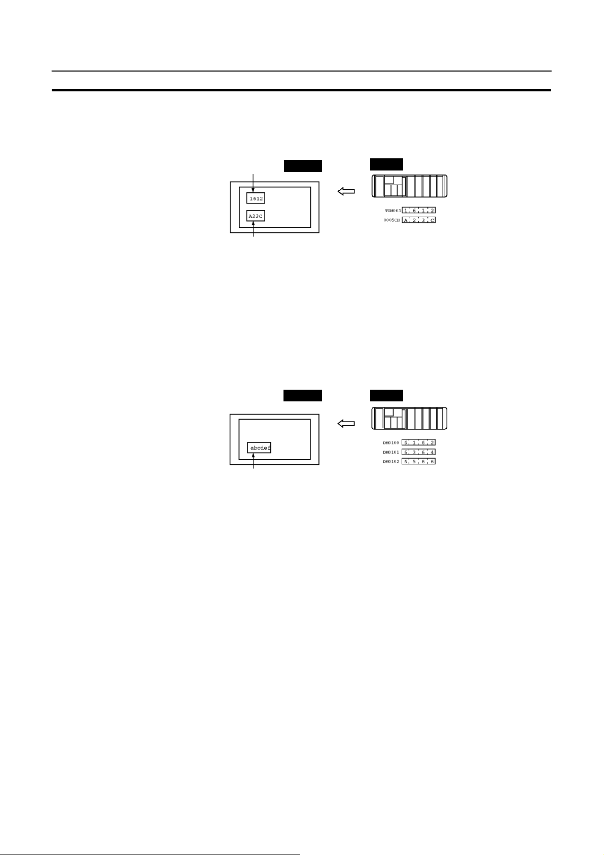
S Character-string memory table
Allocation destination: Word
PC
NT11S PC
(“a”, “b”)
(“c”, “d”)
(“e”, “f”)
Character-string memory table 1
Allocated word number: 3ch
First word: DM0100
Allocate character-string memory tables to arbitrary words in the PC. If word
contents change when corresponding character-string memory table is displayed onthe screen,thevalue onthe screenwill also change.Messages canbe
displayed easily.
Reading and writing are executed so that the contents of allocated words are
always the same as those of the character-string memory tables.
13
Page 30
Direct Connection Function
Functions of the PT Status Control Area (PC to NT11S)
The “PT status control area” is used to control the NT11S status. When data is
written to this areain the PC, the NT11S readsthe contents and operates according to the contents.
[Example of the PT status control area application]
When data is written to the PT status control area, the NT11S willoperateasgiven
below.
Section 1-5
Copy
Screen 3
display
Numeral memory table 50
Numeral memory table 7
NT11S PC
Printing of daily reports or display histories
Functions of the PT Status Notify Area (NT11S to PC)
The “PT status notify area” is used to notify the changes of the NT11S status.
When a change is made in the NT11S status, the change is written to this area in
the PC. By reading the data from the area, the NT11S status can be checked.
[Example of the PT status notify area application]
PT status control area
0003
0050
1007
8010
Screen switch setting
Memory table
Copy setting
PT status control bits
14
When achange ismade inthe NT11S status, suchchange willbe notifiedto the PT
status notify area as mentioned below.
NT11S PC
Numeral memory table 13
12345678
12345678
PT status notify area
Allocated word (numeral table 13)
12345678
Currently display screen
Content update memory table
PT status
Start
Start + 1
Page 31

Before Operating
PCs
1-6 Before Operating
Follow the procedure given below to start the system of the NT11S.
PC NT11S Support tool
Section 1-6
Check and change the
PC settings.
S For the host link, refer
to page 26 and the
manuals for the host
link unit and peripheral
tools.
S For the NT link, refer
to page 37.
Connect to the NT11S.
Create the PC program.
Start operation.
Set the DIP switches.
(page 20)
Install to the operation
panel.
(page 22)
Connect the power supply.
(page 23)
Connect to the PC.
S (Host link: page 26)
S (NT link: page 37)
Check the settings and
communications.
Transfer the
screen data.
(page 54)
Install the support tool
in the computer.
Transfer the system
program by using the
system transfer tool.
Create the screens.
(refer to Section 4 and the
manuals for the support tools)
Reference
Use support tool NT11S Support Tool (type NT11S-ZA3AT-EV1).
Refer to the following manuals for the equipment and software.
Equipment or Software Manual Title Manual Number
Support tools NT-series NT11S Support Tool Operation Manual V030-E1-j
PCs SYSMAC C200H Operation Manual W130-E1-j
SYSMAC C200HS Operation Manual W235-E1-j
SYSMAC CQM1-CPM1 Programming Manual W228-E1-j
Host link Unit SYSMAC C Series Host Link Unit User’s Manual W143-E1-j
15
Page 32

16
Page 33

Hardware Settings and Connections
This section describes the settings of the NT11S, connections to a PC, and other hardware settings.
2-1 Description of Parts and Settings 18. . . . . . . . . . . . . . . . . . . . . . . . . . . . . . . . . . . . . . . . . . . . . . . .
2-1-1 Description of Parts 18. . . . . . . . . . . . . . . . . . . . . . . . . . . . . . . . . . . . . . . . . . . . . . . . . . . . .
2-1-2 DIP Switch Settings 20. . . . . . . . . . . . . . . . . . . . . . . . . . . . . . . . . . . . . . . . . . . . . . . . . . . . .
2-2 Installation 22. . . . . . . . . . . . . . . . . . . . . . . . . . . . . . . . . . . . . . . . . . . . . . . . . . . . . . . . . . . . . . . . . .
2-2-1 Installation to the Operation Panel 22. . . . . . . . . . . . . . . . . . . . . . . . . . . . . . . . . . . . . . . . .
2-2-2 Power Supply Connection 23. . . . . . . . . . . . . . . . . . . . . . . . . . . . . . . . . . . . . . . . . . . . . . . .
2-2-3 Grounding 24. . . . . . . . . . . . . . . . . . . . . . . . . . . . . . . . . . . . . . . . . . . . . . . . . . . . . . . . . . . .
2-3 Connecting to the Support Tool 25. . . . . . . . . . . . . . . . . . . . . . . . . . . . . . . . . . . . . . . . . . . . . . . . .
2-4 Connection to a PC by the Host Link (RS-232C Type) 26. . . . . . . . . . . . . . . . . . . . . . . . . . . . . . .
2-4-1 Compatible PCs 26. . . . . . . . . . . . . . . . . . . . . . . . . . . . . . . . . . . . . . . . . . . . . . . . . . . . . . . .
2-4-2 Connecting the NT11S 27. . . . . . . . . . . . . . . . . . . . . . . . . . . . . . . . . . . . . . . . . . . . . . . . . . .
2-4-3 PC Switch Settings 28. . . . . . . . . . . . . . . . . . . . . . . . . . . . . . . . . . . . . . . . . . . . . . . . . . . . . .
2-5 Connection to a PC by the Host Link (RS-422A Type) 31. . . . . . . . . . . . . . . . . . . . . . . . . . . . . . .
2-5-1 Compatible PCs 31. . . . . . . . . . . . . . . . . . . . . . . . . . . . . . . . . . . . . . . . . . . . . . . . . . . . . . . .
2-5-2 Parts Required for Connection 32. . . . . . . . . . . . . . . . . . . . . . . . . . . . . . . . . . . . . . . . . . . . .
2-5-3 Method for Connection 33. . . . . . . . . . . . . . . . . . . . . . . . . . . . . . . . . . . . . . . . . . . . . . . . . .
2-5-4 Connector Specifications and Wiring for Each Unit 34. . . . . . . . . . . . . . . . . . . . . . . . . . . .
2-5-5 PC Switch Settings 35. . . . . . . . . . . . . . . . . . . . . . . . . . . . . . . . . . . . . . . . . . . . . . . . . . . . . .
2-6 Connection to a PC by the NT Link 37. . . . . . . . . . . . . . . . . . . . . . . . . . . . . . . . . . . . . . . . . . . . . .
2-6-1 Compatible PCs 37. . . . . . . . . . . . . . . . . . . . . . . . . . . . . . . . . . . . . . . . . . . . . . . . . . . . . . . .
2-6-2 Connecting the NT11S 37. . . . . . . . . . . . . . . . . . . . . . . . . . . . . . . . . . . . . . . . . . . . . . . . . . .
2-6-3 PC Switch Settings 38. . . . . . . . . . . . . . . . . . . . . . . . . . . . . . . . . . . . . . . . . . . . . . . . . . . . . .
2-7 Connecting a Printer 39. . . . . . . . . . . . . . . . . . . . . . . . . . . . . . . . . . . . . . . . . . . . . . . . . . . . . . . . . .
2-7-1 How to Connect 39. . . . . . . . . . . . . . . . . . . . . . . . . . . . . . . . . . . . . . . . . . . . . . . . . . . . . . . .
SECTION 2
17
Page 34

Description of Parts and Settings
2-1 Description of Parts and Settings
Before getting to the operation, confirm the names and functions of parts. Alsoset
the DIP switches on the NT11S.
2-1-1 Description of Parts
Front View
POWER LED
Lit when the
power is supplied.
RUN LED
Lit when the
communication
status is normal
Section 2-1
Arrow keys
Used to select the
required numerical
value input field when
there is more than one
on the screen.
Numeric keys
Used for inputting
numerical values on
screens that require
numerical value input.
Reference
Function keys
Used for direct
notifications to the PC.
Display
An LCD screen with a backlight.
The NT11S comes in two body colors.
S NT11S-ST121 : Beige
S NT11S-ST121B: Black
18
Page 35

Description of Parts and Settings
Rear View
Section 2-1
Connector for parallel interface connection
Connect the printer cable here.
(Interface conforms to Centronics specifications)
RS-422A terminal block
Connect the PC cable here.
Contrast control
Use a fine philips screwdriver.
Turn clockwise to increase the brightness.
DIP switch
Set various system statuses
with these switches.
Reset switch
Initializes the NT11S statuses. Note that for the
image data memory and the memory switch,
the status before the initialization is retained.
Power input terminals
Connect the power to the
NT11S at these terminals.
RS-232C connector
Connect the cable that connects
the PC or support tool here.
19
Page 36

Description of Parts and Settings
SW2-1
SW2-2
SW2-3
SW2-4
SW2-6
2-1-2 DIP Switch Settings
Set the NT11S operation status with the DIP switches located in the bottom right
corner on the rear side of the body.
Switch # Function
SW2-1 RS-422A terminal resistor connection
SW2-2 Screen data forced initialize effective/ineffective
SW2-3 Screen display language mode
SW2-4 Switching to the System Menu enabled/disabled
SW2-5 Not used.
SW2-6 System program erase
Section 2-1
ON Terminal resistor used
[OFF] Terminal resistor not used
ON The NT11S will start in a special RUN mode in which the screen
data memory is initialized. When it is started, the memory initialization menu will be displayed. For the initialization procedure,
refer to Section 3-4 Initializing Memory (page 48).
[OFF] The NT11S will start in normal RUN mode.
ON
[OFF] Messages are displayed in English.
ON The System Menu cannot be displayed. If an error occurs during
a start-up, the System Menu will be automatically displayed.
However, “RUN Mode” cannot be entered.
[OFF] The System Menu can be displayed.
ON The menu for deleting the system program is displayed on strat-up.
[OFF] Start-up proceeds as normal.
[ ] indicates factory setting.
20
Page 37

Description of Parts and Settings
Section 2-1
Caution
Correct Use
S In addition to the DIP switches, set also the “Comm. Method”, “Host Link
Speed”, “Automatic Reset”, etc. at the memory switches. For these settings, refer to Section3-7“Setting the Conditions of Communications with thePCbyUsing the Memory Switches” (page 57)
S After changing the switch settings, always press the reset switch or turn the
power off and back on.
Otherwise the system will not operate as expected.
S Confirm system safety before turning the power ON/OFF or resetting.
Otherwise the system may operate unpredictably.
Use the “System program erase” function only when changing the system program.
It the system program is erased, it will not be possible to use the functions of the
NT11S unless another system program is transferred.
If the DIP switch settings have been changed when the NT11S is powered, reset
the power to the NT11S. The changes with the DIP switches become effective
only after the power supply is reset.
21
Page 38

Installation
2-2 Installation
Section 2-2
Install the NT11S to the operation panel and connect the power to the NT11S as
described below.
Correct Use
Do not install the unit at sites subject to the following conditions.
Otherwise, the product may malfunction.
S Severe temperature variations
S Temperatures or humidities outside the ranges stated in the specifications
S High humidity, condensation
S Splashing chemical agents
S Severe oil splashing
S Corrosive or flammable gases
S Strong vibrations or shocks
S Direct exposure to wind and rain (outdoor sites)
S Strong ultra-violet irradiation
Take adequate measures to ensure shielding if the unit is used at a location subject to any of the following conditions. Otherwise, the product may malfunction.
S Static electricity, or noise from other equipment
S Strong electromagnetic fields
S Nearby power cables
S Potential exposure to radioactivity
2-2-1 Installation to the Operation Panel
The NT11S can be flush mounted to an operation panel.
Caution
Use the panel fittings and toolsincludedin the productpackage andfollowtheprocedure below.
S On unpacking the unit, check its external appearance and confirm that there is
no damage. Also confirm that there is no abnormal noise on shaking the unit
lightly. The product may malfunction if it is damaged.
S During work atthe panel,takecareto ensurethat no metal scrapsentertheunit.
Otherwise, the product may malfunction.
S The thickness of applicable operation panel is 1.6 mm to 4.8 mm. All fittings
must betightened uniformly to a torque of 0.5 to0.6 Nm in order to ensure water- and dust-resistance. The panel must not be soiled or warped, and must be
able to support an installation that will remain secure and strong.
(1) Open a hole, shown below, in the panel and install the NT11S from the front
side of the panel.
+0.5 mm
98.8
0 mm
+0.5 mm
204.2
0 mm
22
Page 39

Installation
(2) Attach the panel fittings at four positions for the upper/lower sides and at two
positions for the right and left sides, shown below, on the rear side of the
NT11S.
Fit the hook of the fitting in the square hole in the body and tighten the screw
with a Phillips head screwdriver while lightly pulling the fitting.
2-2-2 Power Supply Connection
Connect a 24 VDC power supply to the power input terminals.
Section 2-2
Caution
S Carefully check the wiring before switching ON the power.
S Do not connect AC power to the DC terminals.
S Use DC and AC power supplies with low voltage and frequency fluctuations.
0v 24v
+
Breaker
24 VDC Power Supply
S Noise prevention
The NT11S has a noise preventive feature against the power supply line noise.
To further reduce noise, connect a noise filter to the power line. This will drastically reduce the ground noise.
S Power supply
Applicable power supply specifications are as follows.
Item Value
Power supply voltage 24 VDC
Allowable power supply voltage
fluctuation range
Power supply capacity 10 W or lower
20.4 VDC to 26.4 VDC
(24 VDC --15%, +10%)
S Parts used for connection
Use crimp terminals to connect the power supply to the power input terminals.
Recommended crimp terminals for M3.5 are given below.
23
Page 40

Installation
Section 2-2
Caution
2-2-3 Grounding
For the connection to the power supply terminal block, twisted wires of 2 mm2or
greater cross sectional area and M 3.5 size crimp terminals must be used.
Tighten the screws on the terminal block to a torque of 0.5 N m.
Otherwise fire may occur.
Fork type Round type
7 mm or less 7 mm or less
[Recommended terminals]
Maker
Japan Solderless Terminal MFG 2-YS3A 2-3.5
Fuji Terminal 2-YAS3.5 V2-S3.5
Nichifu Terminal 2Y-3.5 2-3.5
Type
(fork type)
Type
(round type)
Applicable Wire
(stranded wire)
1.04 to 2.63 mm
2
Class 3 grounding
(grounding resistance
is 100 W or less)
Correct Use
The NT11S has a Grounding terminal .
To prevent malfunctions due to excessive noise, and to prevent electric shock,
carry outclass3 grounding (groundingresistance of100 or less)using aspecialpurpose grounding cable (wire of at least 2 mm2).
Grounding wire length should be less than 20 m.
Note that if grounding wire is used in common with other equipment, or if it is con-
nected to a beam of a building, for example, the NT11S might be adversely affected by this grounding.
Other
equipment
Other
equipment
Grounding common to several pieces of equipment:¼IncorrectGrounding for individual equipment:¼Correct
NT11SNT11SNT11S
Other
equipment
(After noting grounding details in this text.)
Carry out grounding correctly in order to prevent misoperation due to noise.
24
Page 41

Connecting to the Support Tool
2-3 Connecting to the Support Tool
Connect the NT11S to a computer with an RS-232C cable to transfer the screen
data created byusing asupport tooland theNT11S system programto theNT11S.
S Communication conditions
Communication conditions aresetwhen asupport tool or system transfer tool is
started.
Section 2-3
Reference
S Connecting cable
Make the cable for connecting the NT11S to the support tool or system transfer
tool by referring to Appendix E “Making the Cable for Connection to the Support
Tool”.
It is impossible to connect a computer and a PC at the same time to the NT11S.
Connect a computer only to transfer the screen data.
25
Page 42

Connection to a PC by the Host Link (RS-232C Type)
PCSerie
s
Connectableto
Cseries
Section 2-4
2-4 Connection to a PC by the Host Link (RS-232C Type)
Connect the NT11S to an OMRON PC by using RS-232C type the host linkmethod.
In order to make a connection to the PC using the host link method (RS-232C
type), the “Comm. Type” memory switch of the NT11S must be set to “host link”,
and the “Comm. Port” memory switch must be set to “RS-232C”. For details on
memory switch settings, see “Selecting the Host Communication Method” (page
58)
2-4-1 Compatible PCs
Some models and series of OMRON PCs have the host link function built in.
Check themodelandseries ofthe PC against thetype of host linkunit before making the connections.
The compatible PCs are listed in the table below.
Units with Built-in Host Link Function
Host Link Unit CPU Unit
C200H-LK201 C200H
C200HS-CPU21-E
C200H-LK201-V1
C200HS-CPU23-E
C200HS-CPU31-E
C200HS-CPU33-E
CQM1-CPU21-E
CQM1-CPU41-E
CQM1-CPU42-E
CQM1-CPU43-E
CQM1-CPU44-E
C200HS
CQM1
26
Page 43

Connection to a PC by the Host Link (RS-232C Type)
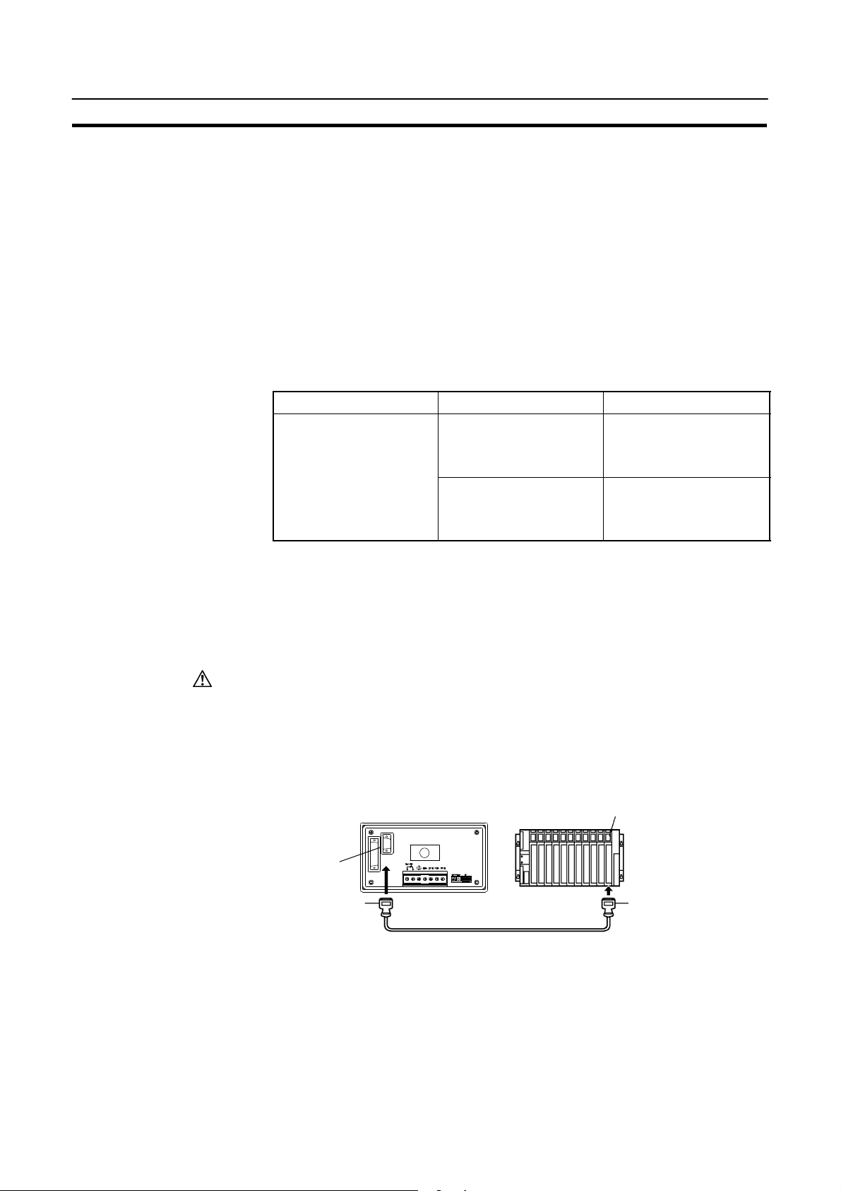
2-4-2 Connecting the NT11S
Refer to the illustrations below to select the appropriate cable for the unit connectors and connect the NT11S to the PC.
To make a connector cable, refer to Appendix D Method for Making the Cable for
Connection to the PC (page 146).
Section 2-4
Caution
S Before inserting or removing the connectors, make sure that theNT11S andthe
PC are turned OFF.
S After connecting a communication cable, always secure it with the screws.
Otherwise the cable may disconnect, causing operation to fail.
S The cable’s tensile load is 30 N. Do not subject it to loads greater than this.
Otherwise a discontinuity may occur, causing operation to fail.
Connecting to a PC with a 25-pin Connector
Use a connector cable with a 25-pin connector on one end and a 9-pin connector
on the other end (NT11S side) to connect the NT11S to aPC with a 25-pinconnector.
Host I/F connector
(RS-232C 9-pin type)
9-pin connector 25-pin connector
Connecting to a PC with a 9-pin Connector
Use a connector cable with a 9-pin connector on both ends to connect the NT11S
to a PC with a 9-pin connector.
NT11S
Host link unit/CPU unit
C200H,
C200HS
RS-232C connector cable
Host I/F connector
(RS-232C 9-pin type)
9-pin connector
NT11S
Host link unit/CPU unit
C200H,
C200HS
9-pin connector
RS-232C connector cable
27
Page 44

Connection to a PC by the Host Link (RS-232C Type)
2-4-3 PC Switch Settings
When theNT11S andPC areconnected to eachother, setthe conditions at thePC
host link unit or the CPU as given in the table below.
The following is a general description of switch settings.
Refer to the manual for respective units for the details of the switch settings.
Item Switch Setting
I/O port RS-232C
Baud rate Set the same baud rate as the NT11S. (*1)
Transfer code ASCII 7 data bits, 2 stop bits
Parity Even
1-to-1/1-to-N 1-to-N (*2)
Instruction level Level 1, 2, 3
Unit No. 00
Section 2-4
Note
*1. Set the host link baud rate at 9600 bps or 19200 bps with the memory switch
for “host link baud rate”. For the details, refer to “Selecting theHost LinkCommunication Speed” (page 59).
*2. The 1-to-N setting enablesBCC (BlockCheck Character).The 1-to-1connec-
tion cannot be used to connect the NT11S to a host link unit.
28
Page 45

Connection to a PC by the Host Link (RS-232C Type)
Connecting to a Host Link Unit
S C200H rack-mounting type: C200H-LK201(--V1)
[Setting the front switches]
Set each switch with a flat blade screwdriver so that the values or symbols in the
setting value window agree with the following.
2
5
[Setting the rear switches]
Section 2-4
S Unit No. (SW1, SW2)
Set these switches to “0”.
S Instruction level, parity, and transfer code (SW4)
Set this switch to “2”.
S Baud rate (SW3)
Set this switch to “5” to select 9600 bps.
Set this switch to “6” to select 19200 bps.
CTS
selector
switch
External
0V (ON)
S 1-to-1/1-to-N selection (DIP switch)
Set No.3 to “ON”.
S CTS selection (selector switch)
Set this always to “0V” (ON).
29
Page 46

Connection to a PC by the Host Link (RS-232C Type)
DM664
6
Connecting to a CPU
S C-series C200HS, CQM1
Set the operating conditions to the PC system setting area when a C200HS or
CQM1 CPU is connected to the NT11S. The PC system setting area (data
memory) can be directly accessed from the peripheral tool (LSS etc.).
The following describes the switch settings so as to enable the PC system settings. For thedetailsof theoperation withthePC systemsetting area,refer tothe
“SYSMAC CQM1-CPM1 Programming Manual” (W228-E1-j).
[Switch setting] (CQM1 only)
[PC system setting area settings]
Write settings to the PC system setting area (data memory) according to the port
used to connect to the NT11S.
Section 2-4
S RS-232C port communication conditions (DIP SW5)
Set SW5 to “ON” to effect the existing settings of the
DIP switches.
Set SW5 to “OFF” to effect the existing settings of the
PC system setting area.
Channel No. Writing Value Settings
DM6645 0001 Host link mode and conditions are set.
0303
0304
DM6648 0000 Unit No. 0
Data length: 7 bits, 2 stop bits, even parity,
baud rate: 9600 bps
Data length: 7 bits, 2 stop bits, even parity,
baud rate: 19200 bps
30
Page 47

Connection to a PC by the Host Link (RS-422A Type)
PCSerie
s
Connectableto
Section 2-5
2-5 Connection to a PC by the Host Link (RS-422A Type)
Connect the NT11S to an OMRON PC by using the RS-422A type host link method.
If the distance between the NT11S and the PC is greater than 15 m, this method
should be used. The maximum distance over which a connection can be made is
500 m.
when using the RS-422A method, the host computer and PC are usually connected in a 1 to N ratio (more than one PC), but in the special case of the connection between the NT11S and PC, the ratio is 1 to 1.
In order to make a connection to the PC using the host link method (RS-422A
type), the“Comm. Type” memory switch of the NT11Smust besettothe host link,
and the “Comm. Port” memory switch must be set to RS-422A. For details on
memory switch settings, see “Selecting the Host Communication Method” (page
58).
2-5-1 Compatible PCs
Some models and series of OMRON PCs have the host link function built in.
Check themodelandseries ofthe PC against thetype of host linkunit before making the connections.
The compatible PCs are listed in the table below.
Units with Built-in Host Link Function
Host Link Unit CPU Unit
C200HS-CPU21-E
C200H-LK201-V1
C200H-LK202-V1
C series
C200HS-CPU23-E
C200HS-CPU31-E
C200HS-CPU33-E
CQM1-CPU21-E
CQM1-CPU41-E
CQM1-CPU42-E
CQM1-CPU43-E
CQM1-CPU44-E
C200HS
CQM1
31
Page 48

Connection to a PC by the Host Link (RS-422A Type)
2-5-2 Parts Required for Connection
The RS-422A cable used for RS-422A communications is not supplied by OMRON. Make thiscablein accordance withtheenvironment (PCused andtransmission distance between the NT11S and PC).
One connector,one connectorcover and one cableare requiredtomakeup aconnecting cable. One connector and one connector cover is supplied with the PC.
However, a cable of the type recommended by OMRON must be prepared.
For details on making the cable, refer to “Making the Cable for Connection to the
PC (RS-422A Type)” in the appendix(page150). The table belowlists the components supplied with each unit and the recommended cables.
Name Model Remarks
Connector XM2A-0901 9-pin, manufactured by OMRON
DE-9P 9-pin, manufactured by JAE
Connector
cover
Cable H-9293A
XM2S-0911 9-pin, manufactured by OMRON
DE-CI-J6 9-pin, manufactured by JAE
(CO-HC-ESV-3P¢7/0.2)
Section 2-5
- Delivered with C series CQM1
- Delivered with the following host link units:
C200H-LK202 (-V1)
- Delivered with the following host link units:
C200H-LK202 (-V1)
- Delivered with C series CQM1
- Delivered with the following host link units:
C200H-LK202 (-V1)
- Delivered with the following host link units:
C200H-LK202 (-V1)
For RS-422A, manufactured by Hirakawa
Hewtech Corp.
32
Page 49

Connection to a PC by the Host Link (RS-422A Type)
2-5-3 Method for Connection
For RS-422A typecommunication, an RS-422A cableis used as the transmission
channel connecting the NT11S and PC.
As shown in the figure below, the RS-422A cable is connected directly to the
NT11S.
Section 2-5
Reference
Caution
NT11S
9-pin connector 9-pin connector
RS-422A terminal
block
RS-422A connector cable
(max. cable length : 500 m)
Host link unit/CPU unit
C200H,
C200HS
Carry out class 3 grounding at the FG terminal of the PC. For details, refer to the
manual for the PC.
Switch off the NT11Spowersupply before connecting or disconnecting aconnector.
33
Page 50

Connection to a PC by the Host Link (RS-422A Type)
SignalNameAbbreviatio
n
Connector
Connector
SignalNameAbbreviatio
n
2-5-4 Connector Specifications and Wiring for Each Unit
The combination of pin numbers to which the connecting wires are connected differs according to the connector specifications for each unit. Check the connector
specifications of the unit to be connected and make the wiring connections by referring to the relevant connection combination among those indicated below.
For details on making the cable, see “Making the Cable for Connection to the PC
(RS-422A Type)” (page 150)
[NT11S RS-422A terminal block specifications]
- Connected terminal block:RS-422A terminal block (M3.5 screws)
- Electrical characteristics: Conform to EIA RS-422A
- Signal direction: Signal input and output is relative to the NT11S
Signal Direction
SDA SDB RDA RDB
Send data A SDA (SD--) f
Send data B SDB (SD+) f
Recive data A RDA (RD--) f
Recive data B RDB (RD+) f
Input Output
Section 2-5
S Connecting an NT11S to a C-series host link unit
[C-series host link connector specifications]
- Applicable host link units: C200H-LK202 (-V1)
- Electrical characteristics: Conform to EIA RS-422A
- Signal direction: Signal input and output is relative to the host link unit.
1
5
6
Pin No.
1 Receive data B RDB f
3 Signal ground SG -- -5 Send data B SDB f
6 Receive data A RDA f
7 Frame ground FG -- --
9
9 Send data A SDA f
[Wiring connections]
NT11S
RS-422A
terminal
block
Abbreviation
SDA
SDB
RDA
RDB
Shielding wire
RS-422A cable
PC (host link unit)
Pin
number
1
3
5
6
7
9
Connector cover
Abbreviation
RDB
SDB
RDA
SDA
SG
FG
FG
Signal Direction
Input Output
RS-422A
interface
34
Page 51

Connection to a PC by the Host Link (RS-422A Type)
2-5-5 PC Switch Settings
When theNT11S andPC areconnected to eachother, setthe conditions at thePC
host link unit or the CPU as given in the table below.
The following is a general description of switch settings.
Refer to the manual for respective units for the details of the switch settings.
Item Switch Setting
I/O port RS-422A
Baud rate Set the same baud rate as the NT11S
Transfer code ASCII 7 data bits, 2 stop bits
Parity Even
1-to-1/1-to-N 1-to-N (*1)
Instruction level Level 1, 2, 3
Unit No. 00
*1. The 1-to-N setting enables BCC (Block Check Character). It is not possible to
connect more than one NT11S in a single host link.
Connecting to a Host Link Unit
S C200H rack-mounting type: C200H-LK201 (-V1)
Section 2-5
C200H-LK202 (-V1)
[Setting the front switches]
Set each switch with a flat blade screwdriver so that the values or symbols in the
setting value window agree with the switch settings indicated in the table above.
LK201
RUN XMT
RCV
SW1
SW3
ERROR
SW2
SW4
S Unit No. (SW1, SW2)
Set these switches to “0”.
S Instruction level, parity, and transfer code (SW4)
Set this switch to “2”.
S Baud rate (SW3)
Set this switch to “5” to select 9600 bps.
Set this switch to “6” to select 19200 bps.
35
Page 52

Connection to a PC by the Host Link (RS-422A Type)
[Setting the rear switches]
C200H-LK201(-V1)
Section 2-5
CTS
selector
switch
External
«
0V (ON)
ON
1 2 3 4
S 1-to-1/1-to-N selection (DIP switch)
Set No. 3 to “ON”.
S CTS selection (selector switch)
Set this always to “0V” (ON).
C200H-LK202(-V1)
This type has an RS-422A connector.
S Terminator setting (selector switch)
CTS
selector
switch
External
«
0V (ON)
Set this switch to “ON”.
Note: Set the link adapter to “ON” also.
1-to-1
protocol
(ON)
«
1-to-N
protocol
(OFF)
S 1-to-1/1-to-N protocol selection (selector switch)
Set this switch to “1-to-N (OFF)”
36
Page 53
Connection to a PC by the NT Link
Cseries
2-6 Connection to a PC by the NT Link
Connect the NT 11S to an OMRON PC by the NT link method.
To connect the NT11S to a PC by the NT link method, the NT11S memory switch
for “host communication” mustbeset forthe NTlink. Forthe“host communication”
setting, refer to “Selecting the Host Communication Method” (page 58)
2-6-1 Compatible PCs
Some models and series of OMRON PCs have the host link function built in.
Check the model and series of the PC against the type of host link unit before
marking the connections.
The compatible PCs are listed in the table below.
PC Series CPU Unit Connectable to
CQM1-CPU41-E
CQM1-CPU42-E
CQM1-CPU43-E
CQM1-CPU44-E
C200HS-CPU21-E
C200HS-CPU23-E
C200HS-CPU31-E
C200HS-CPU33-E
Section 2-6
CQM1
C200HS
2-6-2 Connecting the NT11S
Refer to the illustrations below to select the appropriate cable for the unit connectors and connect the NT11S to the PC.
To make a connector cable, refer to Appendix D Method for Making the Cable for
Connection to the PC (page 146).
Caution
S After connecting a communication cable, always secure it with the screws.
Otherwise the cable may disconnect, causing operation to fail.
S The cable’s tensile load is 30 N. Do not subject it to loads greater than this.
Otherwise a discontinuity may occur, causing operation to fail.
Use a connector cable with a 9-pin connector on both ends to connect the NT11S
to a PC with a 9-pin connector.
Host I/F connector
(RS-232C 9-pin type)
9-pin connector
NT11S
CPU unit
C200HS,
CQM1
9-pin connector
RS-232C connector cable
37
Page 54

Connection to a PC by the NT Link
2-6-3 PC Switch Settings
when the NT11S and PC are connected to each other, set the conditions at the PC
CPU so as to enable the NT link communications.
S C-series C200HS, CQM1
Set the operating conditions to the PC system setting area when a C200HS or
CQM1 CPU is connected to the NT11S. The PC system setting area (data
memory) can be directly accessed from the peripheral tool (LSS etc.).
The following describes the switch settings so as to enable the PC system settings. For thedetailsof theoperation withthePC systemsetting area,refer tothe
“SYSMAC CQM1-CPM1 Programming Manual” (W228-E1-j).
[Switch setting] (CQM1 only)
Section 2-6
S RS-232C port communication conditions (DIP SW5)
Set SW5 to “OFF” to effect the existing settings of the
PC system setting area.
[PC system setting area settings]
Write settings to the PC system setting area (data memory).
Channel No. Writing value Settings
DM6645 4000 NT link is used.
38
Page 55

Connecting a Printer
2-7 Connecting a Printer
Daily reports and display histories can be printed onto a printer connected to the
NT11S.
2-7-1 How to Connect
Connect the printer to the NT11S with a Centronics cable. The length of the cable
should not exceed 3 meters.
Section 2-7
Caution
If the connectioncableis connected ordisconnectedwhilethe powerof the printer
is on, the NT11S may malfunction. Make sure to turn off the power of the printer
before connecting or disconnecting the connection cable.
EPSON ESC/P
Printer (25-pin)
SS Recommended printer
EPSON ESC/P Printer (25-pin)
If using other printer, such printer should conform to ESC/P 24-J81, which is the
printer control standard of Epson.
39
Page 56

40
Page 57

SECTION 3
System Menu Operation
This section describes the operation of the System Menu focusing on the procedure to start up the NT11S.
Functions which will be convenient to use the NT11S and those which are useful for the system maintenance are also explained here.
3-1 Operation Flow by the System Menu 42. . . . . . . . . . . . . . . . . . . . . . . . . . . . . . . . . . . . . . . . . . . . .
3-2 Starting the NT11S 43. . . . . . . . . . . . . . . . . . . . . . . . . . . . . . . . . . . . . . . . . . . . . . . . . . . . . . . . . . .
3-2-1 Changing the System Settings etc. 43. . . . . . . . . . . . . . . . . . . . . . . . . . . . . . . . . . . . . . . . .
3-3 Operation Modes and the System Menu 44. . . . . . . . . . . . . . . . . . . . . . . . . . . . . . . . . . . . . . . . . . .
3-3-1 System Menu and the Operation Modes 44. . . . . . . . . . . . . . . . . . . . . . . . . . . . . . . . . . . . .
3-3-2 Menu Tree 45. . . . . . . . . . . . . . . . . . . . . . . . . . . . . . . . . . . . . . . . . . . . . . . . . . . . . . . . . . . .
3-3-3 Operations with the System Menu 46. . . . . . . . . . . . . . . . . . . . . . . . . . . . . . . . . . . . . . . . . .
3-4 Initializing Memory 48. . . . . . . . . . . . . . . . . . . . . . . . . . . . . . . . . . . . . . . . . . . . . . . . . . . . . . . . . .
3-4-1 Initialization of the Screen Data 48. . . . . . . . . . . . . . . . . . . . . . . . . . . . . . . . . . . . . . . . . . .
3-4-2 Initialization by Using the DIP Switch (Forced Initialization) 50. . . . . . . . . . . . . . . . . . . .
3-5 Transferring the System Program 51. . . . . . . . . . . . . . . . . . . . . . . . . . . . . . . . . . . . . . . . . . . . . . . .
3-6 Registering the Screen Data 54. . . . . . . . . . . . . . . . . . . . . . . . . . . . . . . . . . . . . . . . . . . . . . . . . . . .
3-7 Setting the Conditions of Communications with the PC
by Using the Memory Switches 57. . . . . . . . . . . . . . . . . . . . . . . . . . . . . . . . . . . . . . . . . . . . . . . . .
3-7-1 Selecting the Host Communication Method 58. . . . . . . . . . . . . . . . . . . . . . . . . . . . . . . . . .
3-7-2 Selecting the Host Link Communication Speed 59. . . . . . . . . . . . . . . . . . . . . . . . . . . . . . .
3-7-3 Selecting the Automatic Reset Function 60. . . . . . . . . . . . . . . . . . . . . . . . . . . . . . . . . . . . .
3-7-4 Selecting the Channel for Communication with the PC 61. . . . . . . . . . . . . . . . . . . . . . . . .
3-8 Starting the Operation 62. . . . . . . . . . . . . . . . . . . . . . . . . . . . . . . . . . . . . . . . . . . . . . . . . . . . . . . . .
3-9 Backlight OFF 63. . . . . . . . . . . . . . . . . . . . . . . . . . . . . . . . . . . . . . . . . . . . . . . . . . . . . . . . . . . . . . .
3-9-1 Turning the Backlight Back ON 63. . . . . . . . . . . . . . . . . . . . . . . . . . . . . . . . . . . . . . . . . . .
3-9-2 Backlight OFF Function 63. . . . . . . . . . . . . . . . . . . . . . . . . . . . . . . . . . . . . . . . . . . . . . . . .
3-10 System Maintenance 65. . . . . . . . . . . . . . . . . . . . . . . . . . . . . . . . . . . . . . . . . . . . . . . . . . . . . . . . . .
3-10-1 I/O Check 65. . . . . . . . . . . . . . . . . . . . . . . . . . . . . . . . . . . . . . . . . . . . . . . . . . . . . . . . . . . .
3-10-2 PT Setting Check 69. . . . . . . . . . . . . . . . . . . . . . . . . . . . . . . . . . . . . . . . . . . . . . . . . . . . . .
41
Page 58

Operation Flow by the System Menu
Section 3-1
3-1 Operation Flow by the System Menu
Follow the procedure below when using the NT11S for the first time or when
changing the system.
Create the Screen Data Create the screen data to be displayed on the NT11S by using a support tool.
For the screen data creation, refer to the “NT-series NT11S Support Tool Operation Manual” (V030-E1-1).
Start Up the NT11S (Display the System Menu.) (page 43)
Turn ON the power to the NT11S.
When no screen data has been registered, the “SYSTEM MENU” will be dis-
played. If theNT11S entersthe RUN mode, pressappropriate function keys todisplay the System Menu.
Initialize Memory (page 48) Select a System Menu and initialize the NT11S unit memory.
Transfer the System Program
Connect the NT11S to the system transfer tool and transfer the system program
from the system transfer tool to the NT11S.
For details onconnecting theNT11S to thesystem transfer tool, see 3-5“Transferring the System Program” (page 51).
Transfer the Screen Data (page 54)
Connect asupporttoolto the NT11S and transfer thescreendata from the support
tool to the NT11S.
For the connectionof asupport tool, referto Section 2-3Connecting tothe Support
Tool. (page 25)
Memory Switch Setting (page 57)
Select the System Menu and set the conditions for communications with the PC
using the memory switch.
Start the Operation (page 62)
Connect to the PC and start the operation.
System Maintenance (page 65)
If anerror has occurredduringoperation, check the I/Os, settings, etc. referring to
this guide.
42
Page 59

Starting the NT11S
3-2 Starting the NT11S
When the NT11S is started, it will enter the RUN mode if system settings and
screen data registration have been completed. If no screen data has been registered or the screen data are destroyed, the System Menu will be displayed.
Before turning ON the power, check the following DIP switch settings on the
NT11S.
S SW2-2 “Screen data forced initialize effective/ineffective” is set to OFF (ineffec-
tive).
S DIP SW2-6, “system pragram erase”, is OFF.
For the DIP switch settings of the unit, refer to the “DIP switch settings” (page 20).
3-2-1 Changing the System Settings etc.
Follow the procedure below to change the system settings or screen data contents.
Procedure 1. Switch on the power to the NT11S with two function keys held down to display
the System Menu, thenchange thesystem settings. For themethod for calling
the System Menu, refer to the “Operations with the System Menu” (page 46).
Section 3-2
Reference
If the NT11S has failed to start up normally; an error message is displayed or no
screen is displayed, memory needs to be initialized.
For the memory initializing procedure, refer to Section 3-4 Initializing memory
(page 48).
43
Page 60

Operation Modes and the System Menu
3-3 Operation Modes and the System Menu
The NT11Soperatesineither “RUN”, “Transmit”,or“Maintenance” mode. The operation modes can be switched by using the System Menu.
3-3-1 System Menu and the Operation Modes
Select an operationmode bylocating thecursoron the requireditem withthe ["] [#]
keys, then press [Enter] to confirm the selection. The operation modes with respect to the System Menu are related to each other as shown below.
For the operationswith theSystemMenu,refer tothe “Operations with theSystem
Menu” (page 46).
RUN mode
The NT11S runs in this
state. Controls from the
PC are enabled and
various indications and
I/O operations are made.
To change
system settings
or screen data
contents
Section 3-3
Transmit Mode
Screen data and other
data are transmitted
between the NT11S and
a support tool.
Power
ON
Installed
System
program
installed/
not installed
Not installed
Have system
settings and screen
data registration
been completed?
No
System Program
isn’t installed.
Press ENTER key
to start install
Yes
No
Have two
function keys
been pressed?
ENTER
Yes
SYSTEM MENU
Quit
Transmit Mode
Maintenance Mode
System Transfer Mode
This is the mode in
which the system
program is transferred
form the system transfer
tool to the NT11S.
Maintenance Mode
The NT11S
maintenance operations
such as memory
initialize and setting
check are executed.
44
Page 61

Operation Modes and the System Menu
3-3-2 Menu Tree
The System Menu allows to effect various NT11S functions by using the System
keys. The NT11S’s functions with respect to the System Menu are related as
shown below.
For the operationswith theSystemMenu,refer tothe “Operations with theSystem
Menu” (page 46).
SYSTEM MENU
Quit
Transmit Mode
Maintenance Mode
Section 3-3
MAINTENANCE MENU
PT Setting (page 69)
I/O Check (page 65)
Init. Memory (page 48)
Memory Switch (page 57)
I/O CHECK MENU
Quit
LED (page 65)
LCD (page 66)
Key Check (page 67)
Tool I/F Input Check (page 68)
MEMORY INIT.
Screen memory initialization (page 48)
MEMORY SWITCH MENU
Backlight OFF (page 63)
Automatic Reset (page 60)
Comm. Type Host Link (page 58)
Baud Rate (page 59)
Comm. Port (page 61)
45
Page 62

Operation Modes and the System Menu
3-3-3 Operations with the System Menu
The following givesthe procedureto calltheSystemMenu, selectthe menu items,
and other operations with the System Menu.
Section 3-3
Note
Make sure that DIP SW2-4 “Switching to the System Menu enabled/disabled” is
set to OFF (enabled). If the setting is ON (disabled), the System Menu will not be
displayed by following the procedure given below.
Displaying the System Menu The system menu canbedisplayed by switching onthe power whileanytwo ofthe
four function keys are held down.
Hold down any
two of the four
function keys.
SYSTEM MENU
Quit
Transmit Mode
Maintenance Mode
Basic key operations in the maintenance mode
Operation Function
Any two function keys Cancel
[ENTER] key Set/execute
Arrow keys Cursor motion
Note that on the screen for confirming erasure of the system program, the “Cancel” and “Set/execute” keysare displayed inreversevideo in order to preventmistaken deletion of the program.
Selecting the Menu Items Press the or key on the panel of the NT11S to move the highlighting up or
down. When the required item is highlighted, press the “ENTER” key to select it.
Menu items allow to make the ON/OFF selection or to call subsequent menu or
screen.
Example 1
To callthe “MaintenanceModeMenu” byselecting the“MaintenanceMode” on the
System Menu screen:
46
Page 63

Operation Modes and the System Menu
Section 3-3
SYSTEM MENU
Quit
Select “Maintenance Mode”
with the key, then press “EN-
TER”.
Transmit Mode
Maintenance Mode
PT Setting
I/O Check
Initialize Memory
Memory Switch
System Menu Items The System Menu items and their functions are given below.
Menu Item Function
Quit The System Menu screen is cleared and the NT11S will return to
the RUN mode.
Transmit Mode The Transmit Mode screen will be displayed to allow the trans-
mission of the screen data between the NT11S and the support
tool. For the transmission of the screen data, refer to Section 3-6
Registering the Screen Data (page 54).
Maintenance Mode The Maintenance Mode menu will be displayed to allow the
maintenance of the NT11S system.
Switching from the System Menu to the RUN mode
The NT11S will exit the System Menu and switch to the RUN mode in the cases
mentioned below.
S Selecting “Quit” in the System Menu.
S The screen (System keys) is not pressed for over 10 seconds.
47
Page 64

Initializing Memory
3-4 Initializing Memory
If the NT11S is used for the first time or if the screen data is ruined and the NT11S
cannot be normally started, the memory needs to be initialized.
The memory initialization is required in the cases mentioned below.
S When the NT11S is used for the first time or when an error message indicating
that the screen data is ruined etc. when the NT11S is started.
S When the screen has disappeared during the start-up or operation.
Use the NT11S DIP SW2-2“Screendata forced initialize effective/ineffective”; ini-
tializes the memory.
Section 3-4
Reference
Note
When anerror hasoccurred, theerror messagessuchas “Screendatacorrupted”
will bedisplayed. Fortheerror messages displayed onthe screen,refer toSection
6-2 “Responding to Displayed Error Messages” (page 133).
Initializing the screen data memory will erase entire screen data registered in the
NT11S.Make sure thattherearebackup copiesof the screendataon floppydisks
before starting the initialization.
3-4-1 Initialization of the Screen Data
The screen data can be initialized by either of the following two methods.
S Initialization by using the System Menu
S Initialization by using the DIP switch
48
Page 65

Initializing Memory
Initialization by using the System Menu
Initialize the image data memory by following the procedure given below.
Section 3-4
SYSTEM MENU
Quit
Transmit Mode
Maintenance Mode
PT Setting
I/O Check
Initialize Memory
Memory Switch
Initialize
Screen Memory?
Select “Maintenance Mode”
with the key, then press “EN-
TER”.
Select “Initialize Memory” with
the key, then press“ENTER”.
Press “ENTER”.
Yes:[ENTER]
Initializing
Use the
Support Tool to set
The message shown to the left
is displayed during initialization.
On completion of initialization,
the message shown to the left is
displayed.
the PT Control Area
and PT Notify Area
You can quit without initializing the memory by simultaneously pressing any two of
the function keys while the “Initialize Screen Memory?” screen is displayed.
When the screen data memory initialization has been completed, transfer the
screen data from the support tool.
49
Page 66

Initializing Memory
Section 3-4
3-4-2 Initialization by Using the DIP Switch (Forced Initialization)
Note
Operation 1. Set DIP-SW2-2 on the NT11S to ON and turn the power ON.
Be sure to turn the power OFF before setting the NT11S DIP switch.
Set the DIP switch as follows to initialize the screen data memory.
Press “ENTER”.
Initialize
Screen Memory?
Yes:[ENTER]
The message shown to the left
Initializing
Initialized the
Turn OFF the DIP-SW2-2
is displayed during initialization.
On completion of initialization,
the message shown to the left is
displayed.
Reference
and Reset, then
return to RUN mode
2. Turn the NT11S power to OFF.
3. Set NT11S DIP SW2-2 to OFF and turn the power ON.
You can quit without initializing the memory by simultaneously pressing any two of
the function keys while the “Initialize Screen Memory?” screen is displayed.
Turn OFF the DIP-SW2-2
and Reset, then
return to RUN mode
To change the system settings or to register the screen data, set DIP-SW2-2 to
OFF and callthe System Menu screen byturningon thepowerto the NT11S while
pressing two of the four function keys.
The NT11S DIP-SW2-2 is used to set “Screen data forced initialize effective/ineffective”. Setting this to ON selects “effective”, and OFF “ineffective”.
50
Page 67

Transferring the System Program
3-5 Transferring the System Program
The system program of NT11S can be changed by the system transfer tool.
The system transfer tool is automatically installed in the personal computer when
the NT11S support tool is installed.
For details on how to start up the systemtransfer tool,andthe system transfer tool
operation, refer to the NT-series NT11S Support Tool Operation Manual
(V030-E1-j).
Section 3-5
Note
Transferring the system program from the system transfer tool
Reference
Operation 1. Connect theNT11S tothepersonal computerrunning thesystem transfer tool,
An NT11S which has no system program registered in it will be able to execute
only installation function.
For details on system transfer tool operations, refer to the NT-series NT11S Support Tool Operation Manual (V030-E1-j).
In order to transfer the system program from the system transfer tool, first connect
the NT11S to a personal computer running the system transfer tool by using the
appropriate cable, then proceed as follows.
The NT11S uses oneconnectorfor theconnectiontoboth aPCanda computer. If
it has been connected to a PC, disconnect the PC and connect the system transfer tool (computer) to the NT11S, and then, transmit the screen data.
then switch on the power to the NT11S.
2. Switch onthe power tothe personal computer andstart up the system transfer
tool.
3. When thepower to the NT11S is switched ON, the screen shown below is dis-
played.
System Program
isn’t installed.
Press ENTER key
to start install
51
Page 68

Transferring the System Program
4. Press the “return” key to enter the system transfer mode, as shown below.
5. The NT11S is now on standby for reception. Start transfer of the program by
6. When transfer of the system program is completed, the NT11S displays the
Section 3-5
INSTALL MODE
using the system transfer tool.
When the NT11S starts reception, the screen shown below is displayed.
INSTALL MODE
downloading...
screen shown below.
Downloading is
completed.
Press any key to run
7. Pressing any key when using the system transfer tool will return you to the
main menu screen.
8. You canquit thesystem transfer modeandreturn tothe RUNmode bysimulta-
neously pressing any two of the four function keys on the panel of the NT11S.
The same result is achieved when the NT11S receives a transfer end instruction from the system transfer tool.
Points to observe during transfer of the system program
If any of the following events, or a system error, occurs during transfer of the system program, the program will not be installed in the NT11S correctly.
S The power to the NT11S is switched off, or the NT11S is reset, during transfer.
S The power to the personal computer that is running the system transfer tool is
switched off, or the personal computer is reset, during transfer.
S The cable connecting the personal computer running the system transfer tool
and theNT11S becomesdisconnected orsustains awire breakageduring trans-
fer.
52
S Transfer is terminated by pressing any two of the function keys on the panel of
the NT11S.
Page 69

Registering the Screen Data
S Transfer is terminated by pressing the ESC key of the personal computer run-
ning the system transfer tool.
In the event of any of the above, there is a possibility that the NT11S will not oper-
ate or that unpredictable malfunctions will occur.
To prevent this, switch DIP switch SW2-6 ON to erase the system program after
the problem hasoccurred. For details onerasing the system programwiththeDIP
switch, refer to “Method for Erasing the System Program” (page 53).
Method for Erasing the System Program
In order to erase the system program, the system program area must be cleared.
On shipment thereisno data inthesystem programareaand therefore thesystem
program can be transferred without having to erase an existing system program
first; however, if asystem program already existsit must be erasedbefore the new
one can be transferred.
The following is the procedure for erasing the system program.
Operation 1. Set DIP SW2-6 to the ON position and turnon the powerorreset: the following
screen will be displayed.
Erase system program
Are you sure?
Section 3-6
(Yes:F3+F4, No:ENT)
2. Press the “return” key if you want to quit without erasing the program. If you do
want to erase the program, press any two of the function keys simultaneously:
this will start erasure of the program.
During erasure, the screen shown below is displayed:
Erasing...
3. On completion of erasure, the screen shown below is displayed. At this point
set DIP SW2-6 to the OFF position and reset the NT11S.
Erasing is completed
Set DIP-SW2-6 to off
and press reset-SW
53
Page 70

Registering the Screen Data
3-6 Registering the Screen Data
The screen data is created by using the support tool and registered to the NT11S
screen data memory. This section describes the procedure to register the screen
data to the NT11S. For the screen data creation and the support tool operation,
refer to the NT-series NT11S Support Tool Operation Manual (V030-E1-1).
Transmission -- Transmission in File Units
The NT11S uses several screens which are switched on its display. The screen
data of one NT11S unit corresponds to the screens created by using the support
tool. Select a file which contains the screen data to be transmitted when selecting
the screen data to be transmitted to the NT11S so that the required screen data
can be transmitted to the NT11S.
It is not possible to send screen data in screen units.
Section 3-6
Screen data file
Screen 1
Screen 2
: :
Screen N
Memory table
Mark data
System memory
Direct connection information
If an error message and the System Menu are displayed immediately after the
NT11S has been started, the screen data memory needs to be initialized.
Transmitting the Screen Data from the Support Tool
To transmit thescreen datafrom the supporttool totheNT11S, connectthe NT11S
to the computer on which the support tool is being used, and follow the procedure
below.
Reference
The NT11S uses oneconnectorfor theconnectiontoboth aPCanda computer. If
it has been connected to a PC, disconnect the PC and connect the support tool
(computer) to the NT11S, and then, transmit the screen data.
All screen data are
transmitted by one operation.
NT11S
Screen 1
Screen 2
Screen N
Memory table
Mark data
System memory
Direct connection information
54
Page 71

Registering the Screen Data
Operation 1. Connect the NT11S to the computer on which the support tool is being used,
Section 3-6
and turn ON the NT11S.
2. Turn ON the computer and start up the support tool.
3. Enter the “Transmit Mode” by operating the menu of the NT11S as mentioned
below.
SYSTEM MENU
Select “Transmit Mode” with the
key, then press “ENTER”.
Quit
Transmit Mode
Maintenance Mode
TRANSMIT MODE
4. Select a screen data to be transmitted to the NT11S in the File Selection
screen of the support tool, and press F-6.
5. The NT11S will display the following screen when the screen data is being
transmitted.
TRANSMIT MODE
Tool PT
Screen Data
0KB
55
Page 72

Registering the Screen Data
6. When the screen data transmission is completed, the support tool will display
the following screen.
-- -- -- -- -- Help Message -- -- -- -- --
Data successfuly transmitted
(Hit any key to continue)
7. Press any key on the support tool to return to the File Selection screen.
8. You can quit the Transmit Mode and return tothe RUN mode bysimultaneous-
ly pressing any two of the four function keys on the panel of the NT11S. The
same result is achieved when the NT11S receives a transfer end instruction
from the support tool.
Precautions to be Observed During the Screen Data Transmission
Section 3-6
When any of the following or a system error occurs during the screen data transmission, the transmitted screen data willnot be registered correctly to the NT11S.
If an error message is displayed in the System Menu and the Transmit Mode cannot be selected, the screen data memory needs to be initialized.
S The power to the NT11S is interrupted or the NT11S is reset.
S The power to the computer on which the support tool is running is interrupted or
thr computer is reset.
S The cable connecting the NT11S to the computer on which the support tool is
running is disconnected or has a broken wire.
S Screen data transfer is terminated by pressing any two of the function keys on
the panel of the NT11S.
S The ESC key on the support tool is pressed to end the transmission.
When the power to the NT11S is turned ON or reset, the screen data is checked.
However, if any of the above occurs during the screen data transmission, the
screen may disappear and other unexpected problems may occur.
In the case of such problems, set DIP-SW2-2 to ON to initialize the memory.
For the memory initialization by using the DIP switch, refer to the “Initialization by
using the DIP switch” (page 50).
56
Page 73

Setting the Conditionsof Communications with the PC byUsing the MemorySwitches
Section 3-7
3-7 Setting the Conditions of Communications with the PC by
Using the Memory Switches
The communications between the NT11S and a PC are called the host communications.
The NT11S can be connected to a PC by the host link or NT link. The link can be
selected by setting the memory switch. Also, the host link baud rate, automatic
reset function, etc. are set with the memory switches.
This section describes the communications condition settings by using the
memory switches.
Memory Switches TheNT11S has the memory areas used to store the PC connection method, com-
munications conditions, system settings, etc. which can be used as the switches
and called the “memory switches”. Since the memory switches use the flash
memory, the stored data can be held even when the power supply is turned OFF.
Setting Functions and the Memory Switch Menu
The memory switches can be set easily by using the memory switch menu in the
System Menu.
The following settingscanbe made with the memory switches. Refer to thesubsequent pages for the details of each setting and function.
[ Memory switch menu ]
Page:
Backlight OFF 10min
Auto-restart Yes
Page:
key
Comm. Type Host Link
Baud Rate 9600BPS
key
Comm. Port RS-232C
Backlight OFF 3-9-2 Backlight OFF Functions (page 63)
Auto-restart 3-7-3 Selecting the Automatic Reset Function
(page 60)
Comm. Type Host Link 3-7-1 Selecting the Host Communication Method
(page 58)
Baud Rate 3-7-2 Selecting the Host Link Communication Speed
(page 59)
Comm. Port 3-7-4 Selecting the Channel for Communication with
the PC (page 61)
57
Page 74

Setting the Conditionsof Communications with the PC byUsing the MemorySwitches
3-7-1 Selecting the Host Communication Method
The NT11Scanbe connected to a PC by the host linkor NT link. Either link can be
selected by setting the “Comm. Type” memory switch. The factory setting has
been made to the “Host link”.
Select the host communication method by the menu operation from the System
Menu as mentioned below.
Section 3-7
SYSTEM MENU
Quit
Transmit Mode
Maintenance Mode
PT Setting
I/O Check
Initialize Memory
Memory Switch
Page:
Backlight OFF 10min
Auto-restart Yes
Select “Maintenance Mode”
with the key, then press “EN-
TER”.
Select “Memory Switch” with the
key, then press “ENTER”.
Display the next screen by
pressing the key.
58
Reference
Page:
Comm. Type Host Link
Baud Rate 9600BPS
Pressing the [+/--] key while
“Comm. Type” is highlighted will
cause the selection for this item
to alternate between “HostLink”
and “NT Link”.
Comm. Port RS-232C
To quit after setting the selection made, press the “ENTER” key. To quit without
setting the selection made, press any two function keys simultaneously.
The communication method must be selected according to the method that the
connecting PC supports.
Page 75

Setting the Conditionsof Communications with the PC byUsing the MemorySwitches
3-7-2 Selecting the Host Link Communication Speed
When the host link is used, the baud rate of the communications with the PC can
be set. Use the “Baud Rate” switch and select 9600 bps or 19200 bps.
The factory setting has been made at 9600 bps.
Select the baudrate ofthecommunication with thePC by themenu operation from
the System Menu as mentioned below.
Section 3-7
SYSTEM MENU
Quit
Transmit Mode
Maintenance Mode
PT Setting
I/O Check
Initialize Memory
Memory Switch
Page:
Backlight OFF 10min
Auto-restart Yes
Select “Maintenance Mode”
with the key, then press “ENTER”.
Select “Memory Switch” with the
key, then press “ENTER”.
Display the next screen by
pressing the key.
Note
Page:
Comm. Type Host Link
Baud Rate 9600BPS
Comm. Port RS-232C
To quit after setting the selection made, press the “ENTER” key. To quit without
setting the selection made, press any two function keys simultaneously.
If the NT link has been selected, the Baud Rate setting does not make anyeffect.
Select “Baud Rate” with the
key.
Pressing the [+/--] key while
“Baud Rate” is highlighted will
cause the selection for this item
to alternate between“9600BPS”
and “19200BPS”.
59
Page 76

Setting the Conditionsof Communications with the PC byUsing the MemorySwitches
3-7-3 Selecting the Automatic Reset Function
The “Auto-restart” memory switch isused toset whether ornot the communication
is automatically reset after the occurrence of a communication error.
The factory setting has been made at “OFF”.
Select the Automatic Reset Function of the communication with the PC by the
menu operation from the System Menu as mentioned below.
Section 3-7
SYSTEM MENU
Quit
Transmit Mode
Maintenance Mode
PT Setting
I/O Check
Initialize Memory
Memory Switch
Page:
Backlight OFF 10min
Auto-restart Yes
Select “Maintenance Mode”
with the key, then press “ENTER”.
Select “Memory Switch” with the
key, then press “ENTER”.
Select “Auto-restart” with the
key.
Pressing the [+/--] keywhile“Automatic Reset” is highlighted will
cause the selection for this item
to alternate between “No” and
“Yes”.
60
To quit after setting the selection made, press the “ENTER” key. To quit without
setting the selection made, press any two function keys simultaneously.
S “OFF”: If a communication error has occurred, corresponding error message is
displayed and the operation stops.
S “ON”: If a communication error has occurred, corresponding error message will
not be displayed and the operation will be automatically reset.
Page 77

Setting the Conditionsof Communications with the PC byUsing the MemorySwitches
3-7-4 Selecting the Channel for Communication with the PC
The NT11Sallowsselection of RS-232C or RS-422A as the channel(communication port) forcommunication with thePC. The channel tobeused isselected at the
“Comm. Port” item in the memory switch menu.
The setting on shipment is “RS-232C”.
Select the channel by performing the following operations, starting from the system menu.
Section 3-7
SYSTEM MENU
Quit
Transmit Mode
Maintenance Mode
PT Setting
I/O Check
Initialize Memory
Memory Switch
Page:
Backlight OFF 10min
Auto-restart Yes
Select “Maintenance Mode”
with the key, then press “ENTER”.
Select “Memory Switch” with the
key, then press “ENTER”.
Display the next screen by
pressing the key.
Reference
Page:
Comm. Type Host Link
Baud Rate 9600BPS
Comm. Port RS-232C
To quit after setting the selection made, press the “ENTER” key. To quit without
setting the selection made, press any two function keys simultaneously.
Select the system that is supported by the PC to be connected.
Select “Comm. Port” with the
key.
Pressing the [+/--] key while
“Comm. Port” is highlighted will
cause the selection for this item
to alternate between “RS-232C”
and “RS-422A”.
61
Page 78

Starting the Operation
3-8 Starting the Operation
After completing the screen data transmission, connect the NT11S to the PC and
start the operation.
Section 3-8
Caution
Switching to the RUN mode Press the Quit in the System Menu. The start-up screen in the RUN mode will be
Reference
Confirming the Communications between the NT11S and the PC
Carefully check the operation of all screen data and host programs before using
them. If incorrect, the system may operate unpredictably.
Otherwise the system may operate unpredictably.
displayed.
If theNT11S has failed to start correctly; e.g., thestart-up screenisnot displayed,
an errormessage isdisplayed, orthe screenis notdisplayed atall, referto Section
6-2 “Responding to Displayed Error Messages” (page 133) and take appropriate
action.
Execute the PC program and confirm that the following operations are normally
performed.
S Confirm that the NT11S screens switch according to the PC programexecution.
If the screens do not switch correctly, check the connectionbetween the NT11S
and the PC and also check the settings.
Refer to Section 2 Hardware Settings and Connections.
S Confirm that the information selected by the NT11S function keys has been set
in the PC by displaying the contents of the words and bits using a peripheral tool
(LSS etc.). If the information sent from the NT11S has not been correctly received by the PC, check the screen data settings (specifically the switch settings).
Reference
For the details of the screendatacreation, refer to theNT-series NT11S Support
Tool Operation Manual (V030-E1-1).
The start-up screenmust be designated when the screen data iscreated by using
the support tool. If the start-up screen has not been designated, the screen with
screen number1will be displayed.Ifno screendata hasbeen registeredat screen
number 1, the “Screen not registered.” error message will be displayed. For the
screen number setting, refer to Section 4-3 Screen Display (page 80).
62
Page 79

Back light OFF
3-9 Backlight OFF
In order to prevent the formation of an afterimage on the screen, and to maximize
the service life of the backlight, the NT11S has a function for turning off the backlight.
3-9-1 Turning the Backlight Back ON
After the backlight has been switched off by actuation of the backlight OFF function, it will come back on in response to any key operation on the panel of the
NT11S, if a screen is switched or redisplayed by the PC, or if a backlight ON
instruction is received from the PC.
The backlight will not come back on merely because the numerals or characters
displayed on the screen change.
3-9-2 Backlight OFF Function
There are two methods for implementing the backlight OFF function:
- Method whereby the backlight is automatically switched off when there have
been no operations for a set length of time.
(Designated with the memory switches)
- Method whereby the backlight is switched off by an instruction from the PC.
(Designated in the PT status control area)
Section 3-9
For details onthe methodforswitching thebacklight offwith aninstruction from the
PC, see 5-4 “NT11S Status Control” (page 122).
The settings relating to the backlight OFF function that can be made with the
memory switches are: whether or not thebacklight OFF function isused, and - if it
is used - what length of time will elapse before the backlight goes OFF.
The setting on shipment specifies that the backlight will go OFF after a period of
ten minutes during which there are no operations.
Select the backlight OFF time by performing the following operations, starting
from the system menu.
SYSTEM MENU
Quit
Select “Maintenance Mode”
with the key, then press “EN-
TER”.
Transmit Mode
Maintenance Mode
PT Setting
Select “Memory Switch” with the
key, then press “ENTER”.
I/O Check
Initialize Memory
Memory Switch
63
Page 80

Back light OFF
Section 3-9
Reference
Correct Use
Page:
Backlight OFF 10min
Auto-restart Yes
S To quit after setting the selection made, press the “ENTER” key.
To quit without setting the selection made, press any two function keys simultaneously.
S If “None”is selected, the backlight OFF function doesnotoperate. As longas no
operations are performed, the same screen will be displayed indefinitely.
S If “10m” is selected, the backlight will be switched OFF if no operations are per-
formed for ten minutes.
S If “1h” is selected, the backlight will be switched OFF if no operations are per-
formed for one hour.
In order to maximize the service life of the backlight, select “10m” or “1h” if possible.
After images may remain if the same pattern is displayed for a long period.
To prevent the formation of an afterimage, either usethe screen saver function or
periodicaly switch screens.
Pressing the [+/--] key while
“Backlight OFF” is highlighted
will cause the selection for this
item to change cyclically in the
sequence “10m” “1h” “None”.
64
Page 81

System Maintenance
Section 3-10
3-10 System Maintenance
In order to facilitate maintenance, the NT11S is provided with functions including
the I/O check function and a function for confirming the NT11S settings.
3-10-1 I/O Check
The I/O check function checks whether the inputs and outputs for the following
items are normal.
- LEDs
- LCD
- Key input
- Communication interface
LED check Carry out the LED check by performing the following operations, starting from the
system menu.
SYSTEM MENU
Quit
Transmit Mode
Maintenance Mode
PT Setting
I/O Check
Initialize Memory
Memory Switch
Page:
Quit
LED Check
Select “Maintenance Mode”
with the key, then press “ENTER”.
Select “I/O Check” with the
key, then press “ENTER”.
Select “LED Check” with the
key, then press “ENTER”.
LCD Check
The “RUN” LED on the panel of the NT11S will blink.
S To quit the LED check, press any two of the function keys simultaneously.
65
Page 82

System Maintenance
LCD check Checkthe LCD of the NT11S by performing the following operations, starting from
the system menu.
Section 3-10
SYSTEM MENU
Quit
Transmit Mode
Maintenance Mode
PT Setting
I/O Check
Initialize Memory
Memory Switch
Page:
Quit
LED Check
Select “Maintenance Mode”
with the key, then press “ENTER”.
Select “I/O Check” with the
key, then press “ENTER”.
Select “LCD Check” with the
key, then press “ENTER”.
LCD Check
S In the LCDcheck,allof the dots that comprise the screenare displayed,oneat a
time, starting at the top left corner of the screen.
The LCD check is completed when all the dots are displayed.
S To abort the LCD check, press any two function keys simultaneously.
66
Page 83

System Maintenance
Key input check Check the numeric keys, arrow keys, and function keys of the NT11S by perform-
ing the following operations, starting from the system menu.
Section 3-10
SYSTEM MENU
Quit
Transmit Mode
Maintenance Mode
PT Setting
I/O Check
Initialize Memory
Memory Switch
Page:
Quit
LED Check
LCD Check
Select “Maintenance Mode”
with the key, then press “ENTER”.
Select “I/O Check” with the
key, then press “ENTER”.
Display the next page by pressing the key.
Page:
Press “ENTER”.
Key Check
Tool I/F Input Check
All the keys to be checked are displayed on the screen.
F1 F2 F3 F4
Display when
0 1 2 3 4 5 6 7 8
9
. +/-- clr ENTER
S Press each of the numeric keys, arrow keys, and function keys on the panel of
the NT11S in turn.
If the corresponding key in the display is highlighted when the panel key is
pressed, it indicates that the key is operating normally.
the numeric key
[9] is pressed.
S To quit the key input check, press any two of the function keys simultaneously.
67
Page 84

System Maintenance
Check on communication with the support tool
Check the communication betweentheNT11S and support tool by performing the
following operations, starting from the system menu.
Section 3-10
SYSTEM MENU
Quit
Transmit Mode
Maintenance Mode
PT Setting
I/O Check
Initialize Memory
Memory Switch
Page:
Quit
LED Check
Select “Maintenance Mode”
with the key, then press “ENTER”.
Select “I/O Check” with the
key, then press “ENTER”.
Display the next page by pressing the key.
LCD Check
Page:
Key Check
Select “Tool I/F Input Check”
with the key, then press “ENTER”.
Tool I/F Input Check
TOOL I/F INPUT CHECK
S The data received from the connected support tool is displayed in hexadecimal
notation.
68
S To quitthe checkon communication with the supporttool, press any twofunction
keys simultaneously.
Page 85

System Maintenance
Section 3-10
Note
The NT11Susesthe same connector for connection to the support toolto the PC.
If this cable is connected to equipment other than the personal computer running
the support tool, disconnect it from this equipment and connect it to the support
tool before starting the communications check.
3-10-2 PT Setting Check
Display thesettingsof theNT11S onthescreenby performingthe following operations, starting from the system menu.
SYSTEM MENU
PT Setting
I/O Check
Initialize Memory
Quit
Transmit Mode
Maintenance Mode
Select “Maintenance Mode”
with the key, then press “EN-
TER”.
Press “ENTER”.
Memory Switch
Page:
Control Area DM0200
Notify Area DM0300
The PT setting screen comprises twopages. To switch between them, use the
and keys.
Page:
Control Area DM0200
Notify Area DM0300
S The current settings of the NT11S are displayed.
S To quit the PT setting display, press any two function keys simultaneously.
Page:
key
Comm. Type Host Link
Baud Rate 9600BPS
key
Comm. Port RS-232C
69
Page 86

70
Page 87

NT11S Functions
This section describes the functions of the NT11S.
4-1 Creating and Transmitting Screen Data 72. . . . . . . . . . . . . . . . . . . . . . . . . . . . . . . . . . . . . . . . . . .
4-1-1 Setting the Support Tool for Use with the NT11S 72. . . . . . . . . . . . . . . . . . . . . . . . . . . . . .
4-1-2 Creating Screen Data 73. . . . . . . . . . . . . . . . . . . . . . . . . . . . . . . . . . . . . . . . . . . . . . . . . . . .
4-2 Outline of Functions 77. . . . . . . . . . . . . . . . . . . . . . . . . . . . . . . . . . . . . . . . . . . . . . . . . . . . . . . . . .
4-2-1 NT11S Screen 77. . . . . . . . . . . . . . . . . . . . . . . . . . . . . . . . . . . . . . . . . . . . . . . . . . . . . . . . .
4-2-2 Characters and Figures Which can be Displayed 78. . . . . . . . . . . . . . . . . . . . . . . . . . . . . .
4-3 Screen Display 80. . . . . . . . . . . . . . . . . . . . . . . . . . . . . . . . . . . . . . . . . . . . . . . . . . . . . . . . . . . . . . .
4-3-1 Classification of Screens 80. . . . . . . . . . . . . . . . . . . . . . . . . . . . . . . . . . . . . . . . . . . . . . . . .
4-3-2 Screen Attributes 80. . . . . . . . . . . . . . . . . . . . . . . . . . . . . . . . . . . . . . . . . . . . . . . . . . . . . . .
4-4 Memory Tables 81. . . . . . . . . . . . . . . . . . . . . . . . . . . . . . . . . . . . . . . . . . . . . . . . . . . . . . . . . . . . . .
4-4-1 Character-String Memory Table 81. . . . . . . . . . . . . . . . . . . . . . . . . . . . . . . . . . . . . . . . . . .
4-4-2 Numeral Memory Table 82. . . . . . . . . . . . . . . . . . . . . . . . . . . . . . . . . . . . . . . . . . . . . . . . . .
4-5 Bar Graphs 83. . . . . . . . . . . . . . . . . . . . . . . . . . . . . . . . . . . . . . . . . . . . . . . . . . . . . . . . . . . . . . . . . .
4-5-1 Bar Graph Functions 83. . . . . . . . . . . . . . . . . . . . . . . . . . . . . . . . . . . . . . . . . . . . . . . . . . . .
4-6 Numeral Setting 85. . . . . . . . . . . . . . . . . . . . . . . . . . . . . . . . . . . . . . . . . . . . . . . . . . . . . . . . . . . . .
4-6-1 The Numeral Setting Function 85. . . . . . . . . . . . . . . . . . . . . . . . . . . . . . . . . . . . . . . . . . . . .
4-6-2 Using Numeric Keys 86. . . . . . . . . . . . . . . . . . . . . . . . . . . . . . . . . . . . . . . . . . . . . . . . . . . .
4-7 Menu Screen Function 87. . . . . . . . . . . . . . . . . . . . . . . . . . . . . . . . . . . . . . . . . . . . . . . . . . . . . . . .
4-8 Password Screen Display Function 88. . . . . . . . . . . . . . . . . . . . . . . . . . . . . . . . . . . . . . . . . . . . . . .
4-9 Display History Screen Function 90. . . . . . . . . . . . . . . . . . . . . . . . . . . . . . . . . . . . . . . . . . . . . . . .
4-10 Daily Report/Display History Printing Function 91. . . . . . . . . . . . . . . . . . . . . . . . . . . . . . . . . . . .
4-10-1 Printing Daily Reports 91. . . . . . . . . . . . . . . . . . . . . . . . . . . . . . . . . . . . . . . . . . . . . . . . . .
4-10-2 Printing Display Histories 93. . . . . . . . . . . . . . . . . . . . . . . . . . . . . . . . . . . . . . . . . . . . . . .
SECTION 4
71
Page 88

Creating and Transmitting Screen Data
4-1 Creating and Transmitting Screen Data
This section describesbrieflythesupport tool settings requiredfor creating screen
data and the screen data creation procedure.
Section 4-1
Reference
For the details of the support tool and screen data creation, refertothe“NT-series
NT11S Support Tool Operation Manual” (V030-E1-j).
4-1-1 Setting the Support Tool for Use with the NT11S
To create the screen data for the NT11S, make settings with the support tool for
use with the NT11S.
Select “Tool Settings”.
72
Page 89

Creating and Transmitting Screen Data
Section 4-1
4-1-2 Creating Screen Data
Screen Data Creation Method Thescreen datais createdby usingthe support tool.Thesupporttool registers the
screen data used with one NT11S to one file.
Screen data can be created by one of the following three methods:
S creating a new file;
S editing an existing file;
S reading and editing selected screens from an existing file.
Screen Data Creation Procedure
The following gives the basic screen data creation procedure. Required settings
and reference pages are given for each step of the procedure.
á Select “Tool Settings” in the Main Menu to display the “Tool Settings” screen.
Settings of Auto Refresh, Communication Port, etc. are made in this screen.
Refer to “Setting thesupport tool for usewith the NT11S” onthepreviouspage.
73
Page 90

Creating and Transmitting Screen Data
á Select a file used for storing the screen data for the NT11S in the “File List”
screen.
Section 4-1
Select “Edit Screen”.
To create a new file, select “New File”.
To edit an existing file, select a file to edit.
Select “New File” and press [Enter]. Enter filename on completion of creation.
Select “Screen Creation”.
74
Select a screen number to edit in the selected file in the “Screen List” screen.
á While in the “Screen List” screen, press the [F10] (Next page) key, and then,
the [F4] (Direct) key to display the “Direct Connection Information” window in
which the head words in the PC used to allocate the following areas.
Page 91

Creating and Transmitting Screen Data
S PT status control area: Section 5-4 NT11S Status Control (page 122)
S PT status notify area: Section 5-5 Notification of the Operating Status to the PC
(page 126)
S Numeral memory table: 5-2 Memory Tables and Bar Graph (page 106)
S character-string memory table: 5-2 Memory Tables and Bar Graph (page 106)
Section 4-1
Select a screen number and
press [Enter].
Create screen data in the Edit screen of the support tool. Data of one screen can
be created by registering (laying out) the following display elements and attributes
on the screen.
S Numeral display:
Set numbers in the numeral memory table. .....“Numeral Memory Table” (page 82)
S Character-string display:
Set numbers in the character-string memory table. .....“Character-String
Memory Table” (page 81)
S Bar graph:
Set numbers in the numeral memory table. ..... Section 4-5 Bar Graphs (page 83)
S Numeral setting:
Set numbers in the numeral memory table. ..... Section 4-6 Numeral Setting
(page 85)
S Character input: Input fixed character-strings.
75
Page 92

Creating and Transmitting Screen Data
Return to the “Screen List”.
Section 4-1
[Exiting the Edit screen]
[To the File Selection]
Enter filename to newly created screen data.
Return to the “File List”.
Pressing the [F8] (Start-up screen) key allows setting of the screen number to be
displayed when the NT11S is booted.
Transmitting Screen Data to the NT11S
Transmit the screen data created by using the support tool to the NT11S screen
data memory.
Connect the NT11S tothesupport tooland setthe NT11S toTransmit Mode. Then,
press the[F6](Transmit) keyin the“File List”screento transmitthe createdscreen
data to the NT11S.
76
Page 93

Outline of Functions
Section 4-2
For the connection procedure to the support tool, refer to Section 2-3 Connecting
to the Support Tool (page 25). For the transmission of the screen data, refer to
Section 3-6 Registering the Screen Data (page 54).
4-2 Outline of Functions
4-2-1 NT11S Screen
This section gives the outline of the screen which is the basis of all NT11S functions.
For specific operation procedure usinghost link/NT link such as screen switching,
refer to Section 4-3 Screen Display” (page 80).
Composition of the Screen The NT11S screen is composed of horizontal 160 dots x vertical 64dots. Each dot
is set by the combination of the X (horizontal) and Y (vertical) coordinates. The
origin of coordinates (0, 0) is set at the top left corner of the screen.
X coordinate (horizontal)
0
0
159
Y coordinate
(vertical)
63
Coordinates
(x, y)
159, 63
Screen Management The screens displayed on the NT11S are managed by the screen numbers.
Screen numbers are set when the screen data are created by using the support
tool. Up to 250 screens can be set by allocating arbitrarily selected numbers 1 to
250.
The displayscreenscan be switchedorthe start-upscreen canbe set bydesignat-
ing the screen number from the PC.
Special Screen Number Screen number“0” is reservedfor the system asthe no-display screen. Selectthis
to display nothing on the NT11S screen.
77
Page 94

Outline of Functions
4-2-2 Characters and Figures Which can be Displayed
The NT11S screen can display characters, bar graphs, and other various elements.
This section describesthe types andattributes of the charactersandfigures which
can be displayed and do not need to be changed at all.
For the settings, display, and use of the characters, numeric values, and graphs
which change accordingto the system operationstatus andother conditions, refer
to Section 4-4 Memory Tables (page 81) and Section 5-2 Memory Tables and Bar
Graph (page 106).
The power of expression of the screen can be increased by giving various attributes such as the enlarged or reverse display to the characters and figures.
The character and figure attributes canbe set in the edit screen when creating the
screen data by using the support tool.
Types and Attributes of Characters and Figures
The following types of characters can be input by using the support tool and be
displayed during operation.
Section 4-2
Character
Type
Normal height
characters
Marks 8 x 16
Dots
(vertical x
horizontal)
8 x 16
Character Set
Alphanumerics and
symbols
Create by using the
support tool
Maximum Number of
Characters Displayed in One
Screen (without overwriting)
20 characters x 4 lines
(80 characters)
S Marks
A mark is a graphic pattern created by 8 (horizontal x16 (vertical) by using the
support tool. Marks can be handled the same asthe normal size characters. Up
to 64 patterns can be defined within the total screen data.
78
Page 95

Outline of Functions
Section 4-2
S Enlarged display of the characters and marks
The characters and marks can be enlarged to the following scales.
Double
x1 scale
S Reverse and flashing display
Reverse display: The displaybrightnessof the character andthe
Flashing display: Characters are displayed as they flash. The
Reverse and flashing display: The reverse display alternates with the normal
width
scale
background is reversed comparing with the
normal display.
normal display alternates with no-display.
display.
79
Page 96

Screen Display
4-3 Screen Display
This section describes the screen information required for the operation with the
NT11S.
4-3-1 Classification of Screens
The NT11S is provided with the following types of screens which are classified by
the display method.
S Normal screen
S System screen
The screen type is determined by the screen number.
Normal screens (screen numbers 1 to 250)
These screens can be used without restriction by the user to create various kinds
of monitor and setting screens, including fixed displays, character displays, numeral displays, and bar graph displays.
System screen (screen number 0)
The system screen is reserved by the NT11S for system applications.
Section 4-3
Screen No. 0 ..... Blank screen
4-3-2 Screen Attributes
Assigning an attribute to a screen makes it capable of a special function when it is
displayed. For example,whenan attempt ismade todisplaya screenfor whichthe
“password” attribute is set, a message requesting input of the password will be
displayed and the specified screen will not be displayed until the password has
been input.
Set screenattributes for each screen by using the “screenselection”screenof the
support tool.
It is possible to set more than one of the following attributes for a screen.
Numeral setting attribute This attribute makes it possible to use numeric keys on the panel of the NT11S to
input numerical values on screens on which numerical values have to be set.
For numeral setting, the write channel, display position, and display method must
be set.
Password attribute This attribute ensures security by requesting the input of a password before the
screen is displayed.
If an incorrect password is input, the screen will not be displayed.
The password is set as a four-digit numerical value.
Display history attribute The following three types of data are recorded each time a screen is displayed:
80
Display time: Time when the screen was displayed
(month, day, hour, minute)
Screen number: Screen number of the displayed screen
Screen comment:The comment set for the displayed screen
The recorded data can be printed out using the printing function of the NT11S.
Page 97

Memory Tables
Section 4-4
Menu screen attribute This attribute makes it possible to switch to another screen by using the numeric
keys.
Assigning the screen numbers of destination screens to numeric keys [1] through
[4] enables switching to these screens by numeric key input.
4-4 Memory Tables
The NT11Shasthe “character-string memory table” for the characterdataandthe
“numeral memory table” fornumeric data which can be written and updated bythe
PC.
The contents of the memory tables can be set by using the support tool when displaying the memory tables on the screen or by editing the table.
4-4-1 Character-String Memory Table
The character-string memory table isanNT11S internal memory used to store the
character data. Up to 128 character-string memory tables can be used, and up to
20 characters (20 bytes) can bestored in one memory table. The character-string
memory tables at up to 8 positions can be registered in one screen.
Displaying a Character-string
The character-string memory tables are registered with table numbers 0 to 127.
When creating the screen data by using the support tool, set the position on the
screen to display a character-string and also set a character-string number to be
displayed.
When the NT11S is operated, the screen displays the contents of the characterstring memory table.
Characters and Figures Which can be Displayed
The power of expression of the screen can be increased by giving various attributes such as the enlarged or reverse display to the characters of the characterstring memory table.
The character attributes can be set in the edit screen when creating the screen
data by using the support tool.
The following types of characters can be displayed on the NT11S:
Character
Type
Normal height
characters
Marks 8 x 16
(vertical x
horizontal)
S Enlarged display of the characters and marks
Dots
8 x 16
Character Set
Alphanumerics and
symbols
Create by using the
support tool
Maximum Number of
Characters Displayed in One
Screen (without overwriting)
20 characters x 4 lines
(80 characters)
The characters and marks can be enlarged to the following scales.
Double width scale.
81
Page 98

Memory Tables
S Reverse and flashing display
Reverse display: The displaybrightnessof the character andthe
background is reversed comparing with the
normal display.
Flashing display: Characters are displayed as they flash. The
normal display alternates with no-display.
Reverse and flashing display: The reverse display alternates with the normal
display.
Section 4-4
4-4-2 Numeral Memory Table
The numeral memory table isan NT11S internal memory used to store the numeral data. Up to 128 numeral memory tables can be used, andup to eight digits (four
bytes) of numeral data (including signs) can be stored in one numeral memory
table. The numeral memory tables at up to 8 positions can be registered in one
screen.
Displaying a Numeral The numeral memory tables are registered with table numbers 0 to 127.
When creating the screen data by using the support tool, set the position on the
screen to display a numeral and also set a numeral number to be displayed.
When the NT11S is operated, the screen displays the contents of the numeral
memory table.
Also, by relating the numeral memory tables with the bar graphs, the bar graphs
corresponding to the data of the numeral memory tables can be displayed.
Numerals Which can be Displayed
The power of expression of the screen can be increased by giving various attributes such as the enlarged or reverse display to the numerals of the numeral
memory table.
The numeral attributes canbe set in theeditscreenwhen creatingthe screen data
by using the support tool.
The following types of numerals can be displayed on the NT11S:
- Digits of the whole numbers: 1 to 8 digits
- Digits of the decimal fraction: 0 to 7 digits
- Character sizes: Normal
- Enlarged display: Double width
- Sign display setting
- Decimal/hexadecimal display setting
- Zero suppress setting
Reference
Zero suppress setting
The numeral dataare displayedin designateddisplay areas asright-aligned.If the
number of digits of a numeral data is smaller than that of the display area, number
“0”s will be displayed at the vacant digits. These “0”s will not be displayed if the
zero suppress setting is made for “Yes”.
82
Page 99

Bar Graphs
4-5 Bar Graphs
The contents of thenumeral memory tables of the NT11S can bedisplayed as bar
graphs as well as numeral data.
4-5-1 Bar Graph Functions
The bar graph function displays avalue ina bargraph form as a percentage to the
specified value according to the contents of a numeral memory table. Up to 4bar
graphs can be registered in one screen.
S Reference table
The numeral memory table used as the reference for the bar graph display can
be set.
Section 4-5
Note
Bar Graph Attributes The following attributes can be set with the NT11S for the bar graph display:
The bargraphdisplay cannot usehexadecimalnumbers. If hexadecimal numbers
are setinthe referencenumeral memorytable,the bargraph cannot bedisplayed.
Use the support tool to make settings for the bar graph display when creating the
screen data.
S Position and size
The display position and size (length) of a bar graph can be set.
The width of the bar graph can be set in the range of 8 dots.
S Orientation and incremental direction
The type of bar graph displayed by the NT11S has a horizontal orientation and
increments to the right.
Direction: ®
S Graph frame
Select whether or not the graph frame (boundary line of a graph display area)
which indicates the effective display range is displayed.
¬ This frame is not displayed if
“Graph frame: No” has been set.
83
Page 100

Bar Graphs
Section 4-5
S Setting the 100 % value and % display
Set a value which corresponds to 100 % for the “100 % value”. The available
value range is “0 to 99999999” (max. eight digits). For the “% display”, whether
or not the proportion (percentage) of thereference numeral memory table value
to the “100 % value”is displayedin anumeral can beselected.The display value
is calculated as follows:
“% display” value = Numeral memory table value ÷ “100 % value” x 100
For the fontandattributes usedfor thenumeral display, refer to “Numeralswhich
can be displayed” (page 82).
S Display of negative values (less than 0%)
The bar graphis displayedin the rangeof0 %to 100 %. Theend of the bargraph
indicates 0 %. Values below 0 % are indicated as 0 %.
60 %
% display
0 % 100 %
S Display method when the percentage value is in the range 100% to 999%
999 %
% display
0 % 100 %
1-dot-wide space
«
Graph width: 8 dots
S Display method when the percentage value is 1000% or greater
The bar graph will be displayed the same as (2) above.
The percentage value is indicated by three asterisks:
***%
84
 Loading...