

Page 1

Cat. No. V084-E1-01
NT11
Programmable Terminal
USER’S MANUAL
Page 2
NT11 Programmable Terminal
User’s Manual
Produced January 2004
Page 3

iv
Page 4

Notice:
r
f
OMRON products are manufactured for use according to proper procedures by a qualified operator
and only for the purposes described in this manual.
The following conventions are used to indicate and classify precautions in this manual. Always heed
the information provided with them. Failure to heed precautions can result in injury to people or damage to property.
!DANGER Indicates an imminently hazardous situation which, if not avoided, will result in death or
serious injury.
!WARNING Indicates a potentially hazardous situation which, if not avoided, could result in death or
serious injury.
!Caution Indicates a potentially hazardous situation which, if not avoided, may result in minor or
moderate injury, or property damage.
OMRON Product References
All OMRON products are capitalized in this manual. The word “Unit” is also capitalized when it refers to
an OMRON product, regardless of whether or not it appears in the proper name of the product.
The abbreviation “Ch,” which appears in some displays and on some OMRON products, often means
“word” and is abbreviated “Wd” in documentation in this sense.
The abbreviation “PLC” means Programmable Controller. “PC” is used, however, in some Programming Device displays to mean Programmable Controller.
“Host” means a personal computer that controls the NT11.
Visual Aids
The following headings appear in the left column of the manual to help you locate different types of
information.
Ó OMRON, 2004
All rights reserved. No part of this publication may be reproduced, stored in a retrieval system, or transmitted, in any form, o
by any means, mechanical, electronic, photocopying, recording, or otherwise, without the prior written permission o
OMRON.
No patent liability is assumed with respect to the use of the information contained herein. Moreover, because OMRON is constantly striving to improve its high-quality products, the information contained in this manual is subject to change without
notice. Every precaution has been taken in the preparation of this manual. Nevertheless, OMRON assumes no responsibility
for errors or omissions. Neither is any liability assumed for damages resulting from the use of the information contained in
this publication.
Note Indicates information of particular interest for efficient and convenient opera-
tion of the product.
1,2,3... 1. Indicates lists of one sort or another, such as procedures, checklists, etc.
v
Page 5

vi
Page 6

TABLE OF CONTENTS
PRECAUTIONS . . . . . . . . . . . . . . . . . . . . . . . . . . . . . . . . . . . xi
1 Intended Audience. . . . . . . . . . . . . . . . . . . . . . . . . . . . . . . . . . . . . . . . . . . . . . . . . . . . . . . . . xii
2 General Precautions. . . . . . . . . . . . . . . . . . . . . . . . . . . . . . . . . . . . . . . . . . . . . . . . . . . . . . . . xii
3 Safety Precautions . . . . . . . . . . . . . . . . . . . . . . . . . . . . . . . . . . . . . . . . . . . . . . . . . . . . . . . . . xii
SECTION 1
Functions of the NT11 . . . . . . . . . . . . . . . . . . . . . . . . . . . . . . 1
1-1 Getting Starting . . . . . . . . . . . . . . . . . . . . . . . . . . . . . . . . . . . . . . . . . . . . . . . . . . . . . . . . . . . 2
1-2 Role and Operation of NT11 . . . . . . . . . . . . . . . . . . . . . . . . . . . . . . . . . . . . . . . . . . . . . . . . . 2
1-3 Functions of NT11 . . . . . . . . . . . . . . . . . . . . . . . . . . . . . . . . . . . . . . . . . . . . . . . . . . . . . . . . . 4
1-4 System Configuration . . . . . . . . . . . . . . . . . . . . . . . . . . . . . . . . . . . . . . . . . . . . . . . . . . . . . . 8
1-5 Direct Connection Function. . . . . . . . . . . . . . . . . . . . . . . . . . . . . . . . . . . . . . . . . . . . . . . . . .9
1-6 Before Operating . . . . . . . . . . . . . . . . . . . . . . . . . . . . . . . . . . . . . . . . . . . . . . . . . . . . . . . . . . 12
SECTION 2
Hardware Settings and Connections. . . . . . . . . . . . . . . . . . . 15
2-1 Description of Parts and Settings. . . . . . . . . . . . . . . . . . . . . . . . . . . . . . . . . . . . . . . . . . . . . . 16
2-2 Installation . . . . . . . . . . . . . . . . . . . . . . . . . . . . . . . . . . . . . . . . . . . . . . . . . . . . . . . . . . . . . . . 19
2-3 Connecting to the NT Support Tool. . . . . . . . . . . . . . . . . . . . . . . . . . . . . . . . . . . . . . . . . . . . 22
2-4 Connection to a PLC by the Host Link (RS-232C Type) . . . . . . . . . . . . . . . . . . . . . . . . . . . 22
2-5 Connection to a PLC by the Host Link (RS-422A Type) . . . . . . . . . . . . . . . . . . . . . . . . . . . 38
2-6 Connection to a PLC by the NT Link (RS-232C Type) . . . . . . . . . . . . . . . . . . . . . . . . . . . . 50
2-7 Connection to a PLC by the NT Link (RS-422A Type) . . . . . . . . . . . . . . . . . . . . . . . . . . . . 55
2-8 Connecting a Printer . . . . . . . . . . . . . . . . . . . . . . . . . . . . . . . . . . . . . . . . . . . . . . . . . . . . . . . 57
SECTION 3
System Menu Operation. . . . . . . . . . . . . . . . . . . . . . . . . . . . . 59
3-1 Operation Flow by the System Menu . . . . . . . . . . . . . . . . . . . . . . . . . . . . . . . . . . . . . . . . . . 60
3-2 Starting the NT11. . . . . . . . . . . . . . . . . . . . . . . . . . . . . . . . . . . . . . . . . . . . . . . . . . . . . . . . . . 60
3-3 Operation Modes and the System Menu . . . . . . . . . . . . . . . . . . . . . . . . . . . . . . . . . . . . . . . . 61
3-4 Initializing Memory. . . . . . . . . . . . . . . . . . . . . . . . . . . . . . . . . . . . . . . . . . . . . . . . . . . . . . . . 64
3-5 Transferring the System Program . . . . . . . . . . . . . . . . . . . . . . . . . . . . . . . . . . . . . . . . . . . . . 66
3-6 Registering the Screen Data. . . . . . . . . . . . . . . . . . . . . . . . . . . . . . . . . . . . . . . . . . . . . . . . . .69
3-7 Setting the Conditions of Communications with the PLC by Using the Memory Switches. 71
3-8 Starting the Operation . . . . . . . . . . . . . . . . . . . . . . . . . . . . . . . . . . . . . . . . . . . . . . . . . . . . . . 77
3-9 Backlight OFF . . . . . . . . . . . . . . . . . . . . . . . . . . . . . . . . . . . . . . . . . . . . . . . . . . . . . . . . . . . . 78
3-10 System Maintenance . . . . . . . . . . . . . . . . . . . . . . . . . . . . . . . . . . . . . . . . . . . . . . . . . . . . . . . 80
vii
Page 7

TABLE OF CONTENTS
SECTION 4
NT11 Functions . . . . . . . . . . . . . . . . . . . . . . . . . . . . . . . . . . . . 85
4-1 Outline of Functions . . . . . . . . . . . . . . . . . . . . . . . . . . . . . . . . . . . . . . . . . . . . . . . . . . . . . . . 86
4-2 Screen Display. . . . . . . . . . . . . . . . . . . . . . . . . . . . . . . . . . . . . . . . . . . . . . . . . . . . . . . . . . . . 87
4-3 Areas for Control/Notification. . . . . . . . . . . . . . . . . . . . . . . . . . . . . . . . . . . . . . . . . . . . . . . .89
4-4 Memory Tables . . . . . . . . . . . . . . . . . . . . . . . . . . . . . . . . . . . . . . . . . . . . . . . . . . . . . . . . . . . 94
4-5 Bar Graphs. . . . . . . . . . . . . . . . . . . . . . . . . . . . . . . . . . . . . . . . . . . . . . . . . . . . . . . . . . . . . . . 96
4-6 Numeral Setting. . . . . . . . . . . . . . . . . . . . . . . . . . . . . . . . . . . . . . . . . . . . . . . . . . . . . . . . . . . 97
4-7 Menu Screen Function. . . . . . . . . . . . . . . . . . . . . . . . . . . . . . . . . . . . . . . . . . . . . . . . . . . . . . 99
4-8 Password Screen Display Function . . . . . . . . . . . . . . . . . . . . . . . . . . . . . . . . . . . . . . . . . . . . 100
4-9 Display History Screen Function. . . . . . . . . . . . . . . . . . . . . . . . . . . . . . . . . . . . . . . . . . . . . . 101
4-10 Daily Report/Display History Printing Function. . . . . . . . . . . . . . . . . . . . . . . . . . . . . . . . . . 102
SECTION 5
Using Host Link/NT Link. . . . . . . . . . . . . . . . . . . . . . . . . . . . 107
5-1 Screen Creation Procedure . . . . . . . . . . . . . . . . . . . . . . . . . . . . . . . . . . . . . . . . . . . . . . . . . .108
5-2 Outline of Host Link/NT Link Operation . . . . . . . . . . . . . . . . . . . . . . . . . . . . . . . . . . . . . . . 109
5-3 Memory Table Entries and Bar Graph. . . . . . . . . . . . . . . . . . . . . . . . . . . . . . . . . . . . . . . . . . 115
5-4 Numeral Setting. . . . . . . . . . . . . . . . . . . . . . . . . . . . . . . . . . . . . . . . . . . . . . . . . . . . . . . . . . . 126
5-5 NT11 Status Control . . . . . . . . . . . . . . . . . . . . . . . . . . . . . . . . . . . . . . . . . . . . . . . . . . . . . . . 129
5-6 Notification of the Operating Status to the PLC (Determining the NT11 Operating Status) 132
SECTION 6
Troubleshooting and Maintenance . . . . . . . . . . . . . . . . . . . . 135
6-1 Troubleshooting. . . . . . . . . . . . . . . . . . . . . . . . . . . . . . . . . . . . . . . . . . . . . . . . . . . . . . . . . . . 136
6-2 Responding to Displayed Error Messages. . . . . . . . . . . . . . . . . . . . . . . . . . . . . . . . . . . . . . . 138
6-3 Inspection and Cleaning . . . . . . . . . . . . . . . . . . . . . . . . . . . . . . . . . . . . . . . . . . . . . . . . . . . . 142
Appendices
A Specifications . . . . . . . . . . . . . . . . . . . . . . . . . . . . . . . . . . . . . . . . . . . . . . . . . . . . . . . . . . . . 145
B Dimensions . . . . . . . . . . . . . . . . . . . . . . . . . . . . . . . . . . . . . . . . . . . . . . . . . . . . . . . . . . . . . . 149
C Transporting and Storing the NT11 . . . . . . . . . . . . . . . . . . . . . . . . . . . . . . . . . . . . . . . . . . . 151
D Making the Cable . . . . . . . . . . . . . . . . . . . . . . . . . . . . . . . . . . . . . . . . . . . . . . . . . . . . . . . . . 153
E Making the Cable for Connecting a Personal Computer . . . . . . . . . . . . . . . . . . . . . . . . . . . 155
F NT11 Internal Processing . . . . . . . . . . . . . . . . . . . . . . . . . . . . . . . . . . . . . . . . . . . . . . . . . . . 157
G Model List . . . . . . . . . . . . . . . . . . . . . . . . . . . . . . . . . . . . . . . . . . . . . . . . . . . . . . . . . . . . . . . 159
H Special Characters . . . . . . . . . . . . . . . . . . . . . . . . . . . . . . . . . . . . . . . . . . . . . . . . . . . . . . . . 163
Index. . . . . . . . . . . . . . . . . . . . . . . . . . . . . . . . . . . . . . . . . . . . . 165
Revision History . . . . . . . . . . . . . . . . . . . . . . . . . . . . . . . . . . . 169
viii
Page 8

About this Manual:
This manual describes the basic functions and operation procedures of the NT-series programmable
terminal NT11, its operations when connected to a PLC, and includes the sections described below.
Please read this manual carefully and be sure you understand the information provided before
attempting to install and operate the NT-series programmable terminal NT11.
Section 1 describes the operation functions, system configuration, and the direct connection function
of the NT11.
Section 2 describes the hardware settings, installation to an operation panel, connection to optional
devices and PLC.
Section 3 describes the operation of the System Menu and the maintenance of the NT11.
Section 4 describes the functions of the NT11 when it is connected to a PLC.
Section 5 describes how to use the NT11 when it is connected to the PLC using the host link or NT
link.
Section 6 describes the procedures to follow when the NT11 does not operate correctly.
APPENDIX describes the specifications and the method for making connecting cables, and includes
an area list for the PLC.
!WARNING Failure to read and understand the information provided in this manual may result in per-
sonal injury or death, damage to the product, or product failure. Please read each section
in its entirety and be sure you understand the information provided in the section and
related sections before attempting any of the procedures or operations given.
ix
Page 9

Related Manuals and Their Contents:
The related manuals are listed below.
The @ symbol at the end of the manual number is the revision history symbol.
[Operating the programmable terminal and communicating with the host]
• NT11 Programmable Terminal User’s Manual (V084-E1-@)
- - - - - - - - - - - - - - - - - - - - - - - - - - - - - - - - - - - - - - - - - - - - - - - - - - -- - - -- - - -- - - - - This manual
This user’s manual is the manual for the NT11-V@ itself.
The NT11 is a unit which integrates a programmable terminal body. This user’s manual describes the
functions and handling of the programmable terminal body.
[Creating and transferring screen data]
• NT-series Support Tool Operation Manual (V061-E1-@)
The screens displayed on the NT11 are created with the support tool and transferred to the NT11.
This manual describes how to create and transfer screen data.
x
Page 10

PRECAUTIONS
This section provides general precautions for using the Programmable Terminal.
The information contained in this section is important for the safe and reliable application of the Programmable
Terminal. You must read this section and understand the information contained before attempting to set up or
operate a Programmable Terminal.
1 Intended Audience . . . . . . . . . . . . . . . . . . . . . . . . . . . . . . . . . . . . . . . . . . . . . xii
2 General Precautions . . . . . . . . . . . . . . . . . . . . . . . . . . . . . . . . . . . . . . . . . . . . xii
3 Safety Precautions. . . . . . . . . . . . . . . . . . . . . . . . . . . . . . . . . . . . . . . . . . . . . . xii
xi
Page 11

Intended Audience 1
1 Intended Audience
This manual is intended for the following personnel, who must also have
knowledge of electrical systems (an electrical engineer or the equivalent).
• Personnel in charge of introducing FA systems into production facilities.
• Personnel in charge of designing FA systems.
• Personnel in charge of installing and connecting FA systems.
• Personnel in charge of managing FA systems and facilities.
2 General Precautions
The user must operate the product according to the performance specifications described in the user’s manuals.
Before using the product under conditions that are not described in the manual or applying the product to nuclear control systems, railroad systems, aviation systems, vehicles, combustion systems, medical equipment, amusement
machines, safety equipment, and other systems, machines and equipment
that may have a serious influence on lives and property if used improperly,
consult your OMRON representative.
Make sure that the ratings and performance characteristics of the product are
sufficient for the systems, machines, and equipment, and be sure to provide
the systems, machines, and equipment with double safety mechanisms.
This manual provides information for using the Programmable Terminal. Be
sure to read this manual before attempting to use the software and keep this
manual close at hand for reference during operation.
!WARNING It is extremely important that Programmable Terminals and related devices be
used for the specified purpose and under the specified conditions, especially
in applications that can directly or indirectly affect human life. You must consult with your OMRON representative before applying Programmable Terminals to the above-mentioned applications.
!WARNING Do not use input functions such as PT touch switches for applications where
danger to human life or serious damage is possible, or for emergency switch
applications.
3 Safety Precautions
Read these safety precautions carefully and make sure you understand them
before using the Programmable Terminal so that you can use it safely and correctly.
Safety Conventions and
their Meanings
!WARNING Indicates information that, if not heeded, could possibly result in loss of life or
This user’s manual uses the following conventions and symbols to indicate
cautions, warnings, and dangers in order to ensure safe use of the NT11.
The cautions, warnings, and dangers shown here contain important information related to safety. The instructions in these cautions, warnings, and dangers must be observed.
The conventions used and their meanings are presented below.
serious injury.
xii
Page 12

Safety Precautions 3
Caution Indicates information that, if not heeded, could result in relatively serious or mi-
nor injury, damage to the product, or faulty operation.
WARNING
Do not attempt to take the Unit apart and do not touch any
internal parts while the power is being supplied. Doing either of
these may result in electrical shock.
xiii
Page 13

Safety Precautions 3
xiv
Page 14

SECTION 1
Functions of the NT11
NT11 is a new programmable terminal (PT) which incorporates a host interface unit in a programmable terminal body. It
can be easily installed and used.
This section gives the operation examples and characteristics of the NT11 so that you will understand the applications of
the NT11.
1-1 Getting Starting. . . . . . . . . . . . . . . . . . . . . . . . . . . . . . . . . . . . . . . . . . . . . . . . 2
1-2 Role and Operation of NT11. . . . . . . . . . . . . . . . . . . . . . . . . . . . . . . . . . . . . . 2
1-2-1 Operations of NT11 . . . . . . . . . . . . . . . . . . . . . . . . . . . . . . . . . . . . . 3
1-3 Functions of NT11 . . . . . . . . . . . . . . . . . . . . . . . . . . . . . . . . . . . . . . . . . . . . . 4
1-3-1 Features. . . . . . . . . . . . . . . . . . . . . . . . . . . . . . . . . . . . . . . . . . . . . . . 4
1-3-2 Principal Functions of NT11. . . . . . . . . . . . . . . . . . . . . . . . . . . . . . . 5
1-3-3 Displays . . . . . . . . . . . . . . . . . . . . . . . . . . . . . . . . . . . . . . . . . . . . . . 6
1-3-4 System Keys . . . . . . . . . . . . . . . . . . . . . . . . . . . . . . . . . . . . . . . . . . . 7
1-4 System Configuration . . . . . . . . . . . . . . . . . . . . . . . . . . . . . . . . . . . . . . . . . . . 8
1-4-1 Peripheral Devices That Can Be Connected. . . . . . . . . . . . . . . . . . . 8
1-5 Direct Connection Function . . . . . . . . . . . . . . . . . . . . . . . . . . . . . . . . . . . . . . 9
1-5-1 NT Link . . . . . . . . . . . . . . . . . . . . . . . . . . . . . . . . . . . . . . . . . . . . . . 9
1-5-2 Functions of the Allocated Bits and Words . . . . . . . . . . . . . . . . . . . 10
1-6 Before Operating. . . . . . . . . . . . . . . . . . . . . . . . . . . . . . . . . . . . . . . . . . . . . . . 12
1
Page 15

Getting Starting Section 1-1
1-1 Getting Starting
To ensure that the NT11 works correctly, carefully observe the following when
installing and handling it.
Location Do not install the NT11 in a location subject to the following conditions;
• Near a computer, radio transmitter or receiver, etc.
• Dust, chemicals, or steam
• Severe temperature fluctuations
• High humidity and condensation
• Strong electrical or magnetic fields
• Poor ventilation
• Severe vibration
Handling Do not;
• Subject the NT11 to strong shocks or vibrations
• Put heavy objects on the NT11
• Supply a voltage different from the specified voltage
• Disassemble or modify the NT11
Cautions on Cleaning To clean the front panel, use a soft, dry cloth. If it is very dirty, use diluted (2%)
neutral detergent.
Do not use volatile solvents such as benzene, thinner, or a chemically treated
cloth. Their use will cause deformation or discoloration.
Cautions on Afterimage If the same screen contents are kept displayed for a long time, an afterimage
may occur. To prevent this problem, either set the afterimage prevention function or make a program which periodically changes the displayed screen.
Cautions on Operating the System Keys
Do not operate the system keys with sharply pointed objects, such as your fingernails or a screwdriver.
This could break the film.
1-2 Role and Operation of NT11
NT11 is a programmable terminal used to display and transmit the information
in an FA site. The following gives a general description of the role and operation of the NT11 for those who use a programmable terminal (PT) for the first
time.
Production Line Status Monitoring
The NT11 displays real-time information about the system and equipment
operating status, etc.
Line 1 Status
Machine:NT11-SF121
Product: 137 units
75%
2
Page 16
Role and Operation of NT11 Section 1-2
Messages The NT11 warns of system or equipment failures and prompts the appropriate
remedial action.
Alarm
Assembly line B
Positioning pin
Panel Switch Functions The NT11 can be used in place of external data input equipment such as an
operation panel, to transmit data to a PLC.
Positioning
X-AXIS 100 point
Y-AXIS 150 point
Z-AXIS 80 point
1-2-1 Operations of NT11
Displays Screens The information to be displayed (screen data) can be created on a computer
by using support tools and stored in the NT11. The screen data can be displayed on the NT11 in response to the instructions from a PLC or system keys
operation.
PLC
The screen data designated by
instructions from PLC or System
keys operation is displayed.
Receives Data from a PLC NT11 can be connected to a PLC by a host link or NT link and receive neces-
sary data from the PLC.
Host link, NT link
PLC
OMRON's PLC
Sends Data to a PLC Data input through a numeric key can be sent to a PLC.
Numeric keys
PLC
ON/OFF information,
numeric data, etc.
3
Page 17
Functions of NT11 Section 1-3
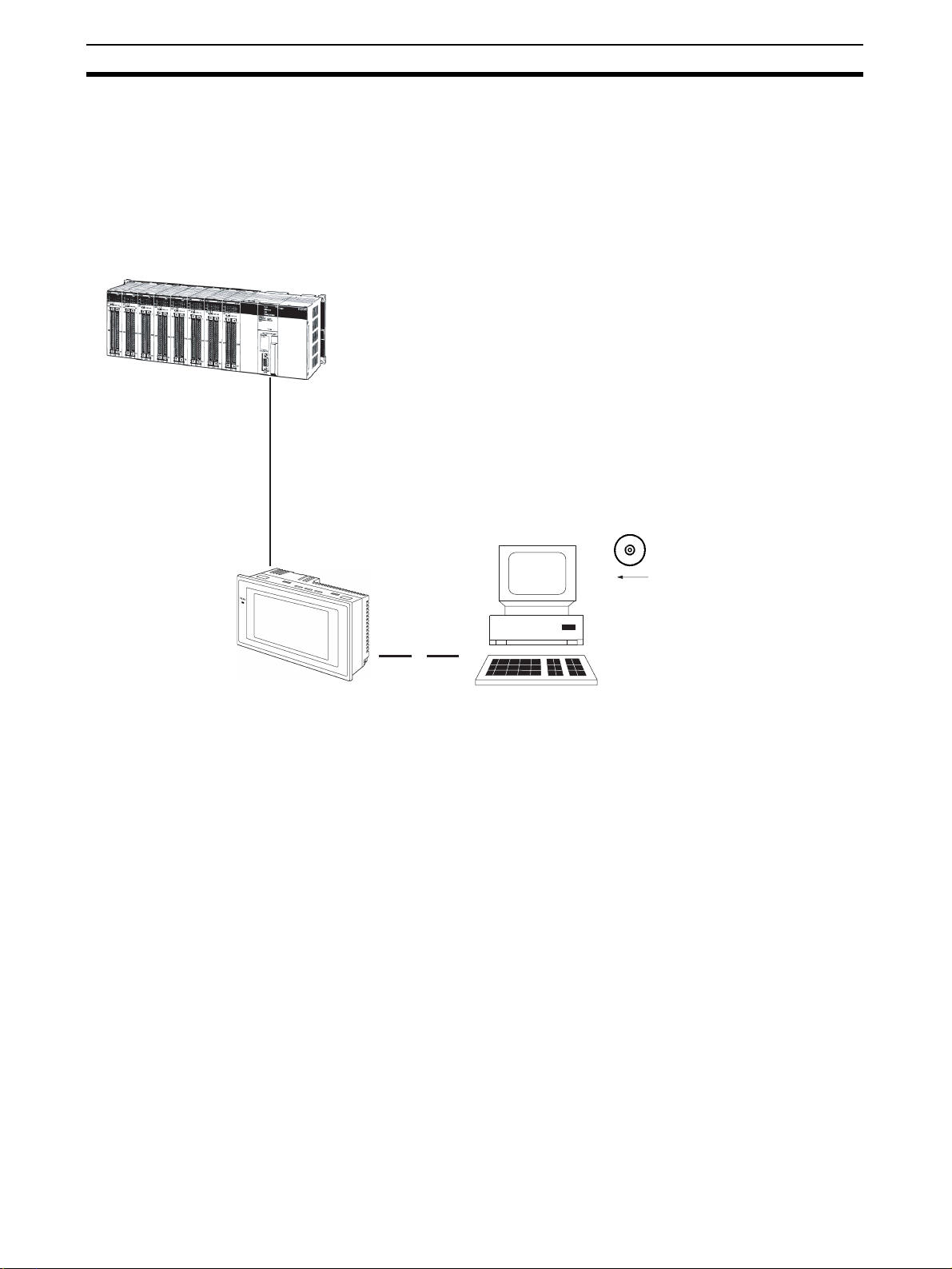
Screen Data The screen data to be displayed on the NT11 can be created by a computer
by using support tools. Connect the NT11 to an IBM PC/AT or compatible with
an RS-232C cable so that the screen data are transferred to the NT11.
Create screen data.
RS-232C
Screen data
PC/AT
(support tools)
This connection is made only to
transmit the screen data by using
NT11 and tools.
1-3 Functions of NT11
The NT11 has the following features and functions;
1-3-1 Features
Downsized Body • The NT11 has the thinnest depth (31 mm or less in the panel) in the NT
series.
• It is very compact, with a width of 218 mm and a height of 113 mm.
• Features three ports: for RS-232C, RS-422A, and printer output.
• The tool connectors and the PLC communication connectors are used in
common.
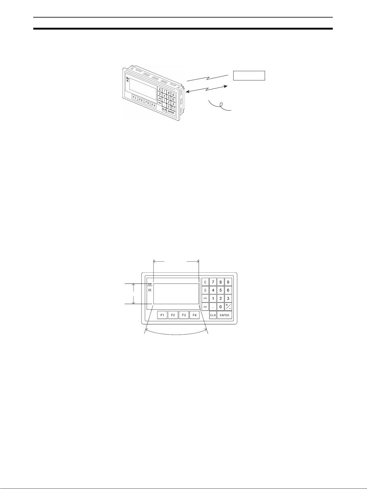
Construction Best Suited to the FA Environment
• Easy-to-read screen even in direct sunlight.
• Waterproofed to a standard equivalent to IP65 and NEMA4.
160 dots
64 dots
Wide angle of visibility ±20°
A Host I/F Unit, Screen Data Memory, and a system program transfer ROM are All Incorporated
• There is no complicated installation work except a simple connection to a
PLC.
• A flash memory is used for the screen data memory. There is no need of
backup battery.
• A host link (direct), and an NT link are standard equipment.
4
Page 18
Functions of NT11 Section 1-3
1-3-2 Principal Functions of NT11
Functions Related to the Data Display
• Character display
Characters of standard and double-width can be displayed. Characters can flash or be
highlighted.
• Memory data display
Contents of the character-string memory table and the numeral memory table can be
displayed. The memory table contents can be changed from the PLC.
• Bar graph display
Bar graphs corresponding to the contents of the numeral table can be displayed.
Functions Related to the Data Input
• Input by the system key
Data can be input, and the displayed screen
changed, by using the numeric keys, function keys,
and arrow keys on the panel of the NT11.
• Numeric setting function
The numeric values can be input at the operation
site by the system key and sent to the PLC.
Other Functions
• Communications with a PLC
The host link, NT link is used to connect to a PLC for data communication.
• System function
The system setting and maintenance can be executed by using the
System Menu on the screen.
• Screen data creation
The screen data can be created by using support tools on the computer
and stored in the unit.
5
Page 19

Functions of NT11 Section 1-3
1-3-3 Displays
The NT11 can display elements such as characters, numeric value, and bar
graphs on a screen. The screen data displayed on the NT11 are created by
using support tools on a computer.
Characters
(character string)
Characters (text)
Bar graph
Characters (text) Characters and marks which do not need to be changed can be written
directly to the screen.
Characters (character-string memory table)
Character-strings stored in the character-string memory table are displayed.
The display characters can be changed by changing the data stored in the
character-string memory table.
Numeric Values (numeral memory table)
Numbers stored in the numeral memory table are displayed. The display numbers can be changed by changing the data stored in the numeral table. Hexadecimal values can also be displayed.
Line 1 Status
Machine:NT11-SF121
Product:137 units
75%
Numeric value
(Numeral table)
Bar Graphs The bar graph extends and contracts in proportion to the data stored in the
numeral memory table. A percentage value can also be displayed simultaneously.
Marks Marks can be designed, created, and handled like characters by the user.
Comparison with the NT11S
Model NT11 NT11S
Basic performance Dimensions 218 x 113 x 38.2 mm (W x H x D)
Resolution 160 x 64 dots (4.24 inches)
Effective display area 100 x 40 mm
Display color Black & white (with yellow mode)
Panel cut-out size (W x H) 204.2 x 98.8 mm
Max. number of registered screens 250
Screen data capacity 32 KB
Function keys 4
Other Keys Numeric Keys, Cursor Keys, Function Keys
Special functions Emergency transfer mode* DIP switch pin 3 None
Backlight service life 50,000 hours min. 10,000 hours min.
Communications Host Link Speed Up to 115,200 9,600/19,200
Compatibility (Screen data types that can
be used.)
* Emergency transfer mode: When power to the NT11 is turned ON with DIP
switch pin 3 turned ON, data transfer mode will be entered directly without
any other operation.
NT11-V1, NT11S NT11S
6
Page 20

Functions of NT11 Section 1-3
1-3-4 System Keys
The NT11 has system keys on its panel for input functions.
The system keys are used for inputting numerical values and for notifications
to the PLC.
The system keys can be classified into the three types shown below.
- Numeric keys
- Arrow keys
- Function keys
NT11
Screen display
Function keys
Arrow keys
Numeric keys
• Numeric keys
These are the numeral keys from [0] to [9], the decimal point key [.], the
sign key [+/–], the [CLR] key and the [ENTER] key. These keys are used
for inputting numerical values.
• Arrow keys
Used to select the required numerical value input field when there is more
than one on the screen.
• Function keys
Used for notifications from the NT11 to the PLC.
Also used to switch between the RUN mode and the system menu when
the power is switched on.
!Caution Do not use input functions such as PT function keys for applications where
danger to human life or serious property damage is possible, or as the emergency stop switch.
!Caution If function keys are pressed in rapid succession, their inputs may not be suc-
cessfully received. Confirm that the input of a function key has been successfully received before moving on to the next operation.
!Caution Do not press function keys carelessly while the backlight is off or while nothing
is displayed on the screen. Otherwise the system may operate unpredictably.
Only press function keys after confirming system safety.
7
Page 21
System Configuration Section 1-4
1-4 System Configuration
This section shows the configuration of a system that uses an NT11. For
details on product models, refer to Appendix G Model List (page 159).
1-4-1 Peripheral Devices That Can Be Connected
The following peripheral devices can be connected to an NT11.
Host
Controls the NT11 as required while controlling machines and monitoring the
production line.
Host Link: CS-series/CJ-series/C-series PLCs, CVM1/CV-series PLCs, SRM1
Can be connected to CPU Units, Host Link Units, and SRM1. However,
connection is not possible to some models of CPU Unit and SRM1
(pages 23 and 39).
NT Link: C-series PLCs, CVM1/CV-series PLCs, SRM1
RS-232C cable
(15 m max.)
An RS-422A/485 cable
(500 m max.) can be
connected through an
RS-232C/RS-422A
Adapter.
Can be connected to CPU Units and SRM1. However, connection is not
possible to some models
Personal computer
Running Windows 95, 98,
NT, 2000, Me, XP
(pages 51 and 55).
NT Support Tool
Used to create screens for the
NT11 at the personal computer
and transfer them to the NT11,
and to make NT11 settings.
NT11
Displays production line monitoring and
commands to the operation site, and
notifies the switch ON/OFF status and
numeric value inputs to the host.
• NT Support Tool (page 22)
NT-series Support Tool Version 4.7 for Windows (Made by OMRON)
• NT-ZJCAT1-EV4.7 (CD-ROM version for IBM PC/AT or compatible
computers)
• System installer (page 22)
System Installer (made by OMRON)
The System Installer is supplied as a standard accessory with the NT Sup-
port Tool (NT-ZJCAT1-EV4.7).
System installer
Used to change the system
program of the NT11.
8
Page 22
Direct Connection Function Section 1-5
1-5 Direct Connection Function
The communication method applied between the NT11 and the PLC is either
a host link or NT link.
The NT11 can be used to refer to the contents necessary for the display information or to allocate the bits and words used for storing the input data to any
area in the PLC. The NT11 can directly write and read such allocated bits and
words so as to change the display elements, control the operating status, and
notify the status.
This function is called the “direct connection function”. The NT11 is designed
exclusively for use with the direct connection.
The bits and words allocated by the direct connection function are called “allocated bit” and “allocated word” respectively.
This function allows to read the information to be displayed on the NT11 from
the memory area in the PLC and to write it to the memory table in the NT11.
Also, the data input on the NT11 can be written to the PLC’s memory area.
The NT11 screen status can be switched according to the PLC’s memory
area, and the NT11’s status data can be written to the PLC’s memory area.
NT11 PLC
Data memory area Internal relay area
Features of the Direct Connection Function
• The bits and words referring to operating status and work instruction information and those for storing input data can be freely allocated to almost
any part of the PLC memory. Bits and words in the PLC can be referenced from any memory table.
• The NT11 can directly refer to PLC bit and word data so that it can be
connected to a PLC without changing the PLC program which controls
currently running production line.
• The area to control and notify the NT11 status, including display screens,
ON/OFF of the backlight, and printing of daily reports and display histories, can be freely allocated to any part of the PLC memory.
The direct connection function allows the NT11 to directly read and write
almost all bits and words in the PLC and to automatically change the NT11
screen display. This function can reduce the load on the PLC so that the program development efficiency of the PLC improves.
1-5-1 NT Link
The NT link is a new communication method applied between the NT11 and a
PLC.
The NT link uses the direct connection function and can execute high speed
communications with a CPU (built-in NT link) of the CQM1, C200HS, and
other PLCs.
Auxiliary relay area
Timer/counter
Features of the NT Link • High speed communications with specific types of PLCs can be executed.
• Writing in units of bits to the PLC memory area is possible. (*)
9
Page 23
Direct Connection Function Section 1-5
)
• This can be used even when the PLC is in the RUN mode.
(*) Except a DM area.
The NT link is compatible with the host link. The NT11 screen data and the
PLC programs handled by the host link direct connection can be used with for
the NT link as they are.
1-5-2 Functions of the Allocated Bits and Words
Elements displayed on the NT11 and the NT11 status can be allocated to the
bits and words of the PLC. By changing the contents of the bits and words, the
NT11 can be controlled by the PLC. It is also possible to send data to the PLC
by pressing the function keys on the panel of the NT11.
• Controlling the NT11 by a PLC
The following NT11 functions can be controlled by a PLC.
Screens: Display of designated screens, confirmation of screen
numbers, etc.
Memory tables: Writing to a memory table, copying from a memory table
to another memory table, etc.
System control: ON/OFF of backlight, control of output of daily reports and
display histories at a printer.
• Notifying from the NT11 to a PLC
Data in the NT11 is sent to a PLC when a numeric key is pressed. The fol-
lowing types of data are sent to a PLC.
- NT11 status
- Password input status
- Numeric values input by the numeral keys
- Function key input status
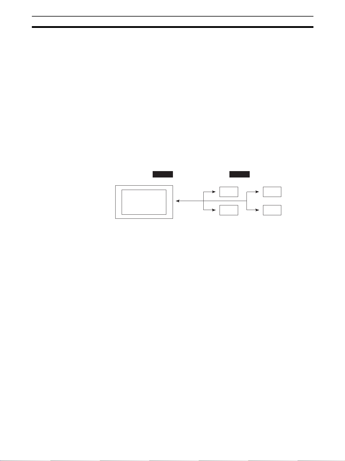
Functions of Display Elements
• Numeral memory table
Allocation destination: Word
Numeral memory
table entry 1
(TIM003)
Numeral memory table entry 150 (CIO/IR 0005
NT11
PLC
CIO/IR 0005
Allocate numeral memory table entries to arbitrary words in the PLC. If word
contents change when corresponding numeral memory table entry is displayed on the screen, the value on the screen will also change. Monitoring of
words can also be made easily.
Reading and writing are executed so that the contents of allocated words are
always the same as those of the numeral memory table entries.
10
Page 24

Direct Connection Function Section 1-5
g
• Character-string memory table
Allocation destination: Word
NT11 PLC
("a", "b")
("c", "d")
("e", "f")
Character-string memory table entry 1
Number of allocated words: 3
First word: DM0100
Allocate character-string memory table entries to arbitrary words in the PLC. If
word contents change when corresponding character-string memory table
entry is displayed on the screen, the value on the screen will also change.
Messages can be displayed easily.
Reading and writing are executed so that the contents of allocated words are
always the same as those of the character-string memory table entries.
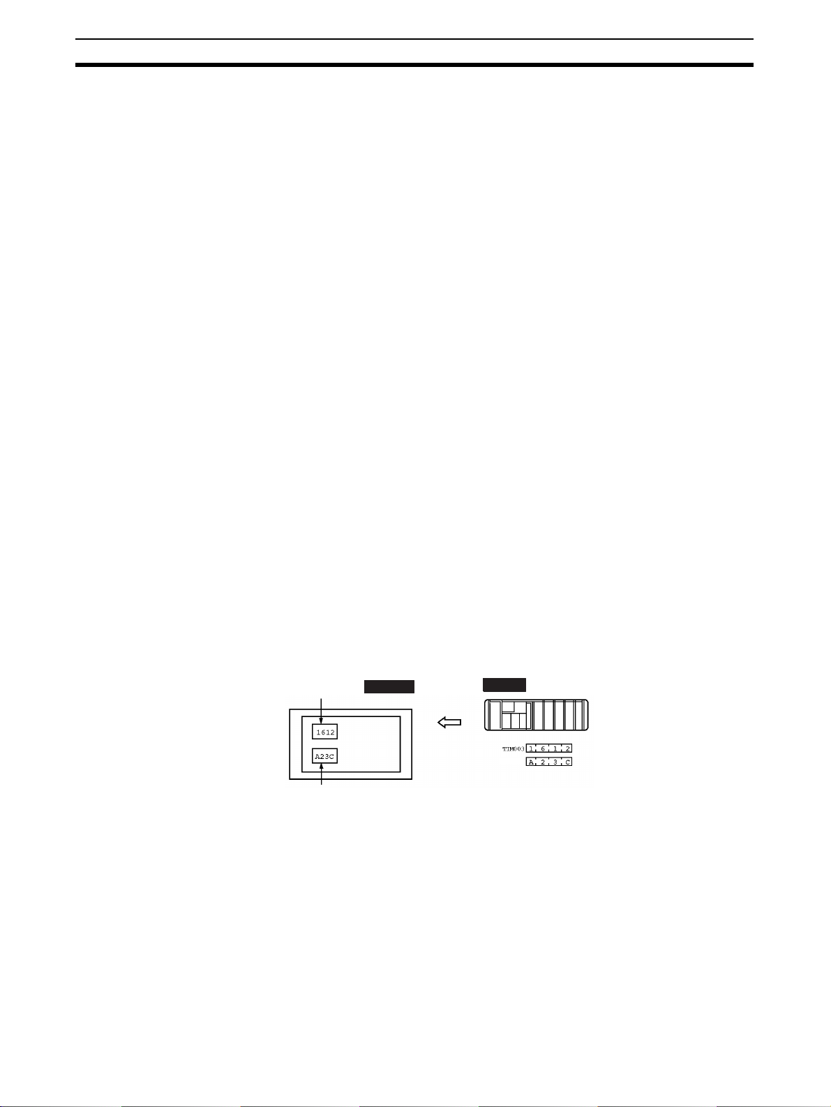
Functions of the PT Status Control Area (PLC to NT11)
The “PT status control area” is used to control the NT11 status. When data is
written to this area in the PLC, the NT11 reads the contents and operates
according to the contents.
[Example of the PT status control area application]
When data is written to the PT status control area, the NT11 will operate as
given below.
Copy
Screen 3
display
Numeral memory table entry 50
Numeral memory table entry 7
Printin
NT11
of daily reports or display histories
Functions of the PT Status Notify Area (NT11 to PLC)
The “PT status notify area” is used to notify the changes of the NT11 status.
When a change is made in the NT11 status, the change is written to this area
in the PLC. By reading the data from the area, the NT11 status can be
checked.
PLC
PT status control area
0003
0050
1007
8010
Screen switch setting
Memory table entry
Copy setting
PT status control bits
11
Page 25
Before Operating Section 1-6
[Example of the PT status notify area application]
When a change is made in the NT11 status, such change will be notified to
the PT status notify area as mentioned below.
12345678
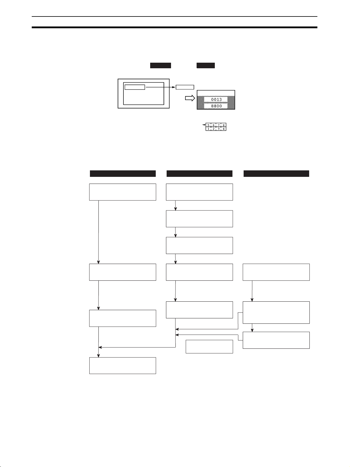
1-6 Before Operating
Follow the procedure given below to start the system of the NT11.
PLC NT11 Support tool
Check and change the
PLC settings.
· For the host link, refer
to page 22 and the
manuals for the host
link unit and peripheral
tools.
· For the NT link, refer to
page 50.
NT11
Numeral memory table entry 13
12345678
12345678
Set the DIP switches.
(page 18)
Install to the operation
panel.
(page 19)
Connect the power supply.
(page 20)
PLC
PT status notify area
Currently display screen
Content update memory table entry
PT status
Allocated word (numeral table 13)
Start
Start + 1
Connect to the NT11.
Create the PLC program.
Start operation.
Connect to the PLC.
· (Host link: page 22)
· (NT link: page 50)
Check the settings and
communications.
Transfer the
screen data.
(page 69)
Install the support tool
in the computer.
Transfer the system
program by using the
system transfer tool.
Create the screens.
(refer to Section 4 and the
manuals for the support tools)
12
Page 26

Before Operating Section 1-6
Reference Use support tool NT-series Support Tool (NT-ZJCAT1-EV4.7).
!Caution Carefully check the operation of all screen data and host programs before
using them.
Otherwise the system may operate unpredictably.
Refer to the following manuals for the equipment and software.
Device or Software Manual Title Cat. No.
NT11 User’s Manual V084-E1-@
System Installer NT-series Support Tool for Windows (Ver. 4.7) Operation Manual V061-E1-@
NT Support Tool NT-series Support Tool for Windows (Ver. 4.7) Operation Manual V061-E1-@
PLC SYSMAC CPM1 Operation Manual W262-E1-@
SYSMAC CPM1A Operation Manual W317-E1-@
SYSMAC CPM2A Operation Manual W352-E1-@
SYSMAC CPM2C Operation Manual W356-E1-@
SYSMAC C200H Operation Manual (for CPU01/03/11) (Programming) W130-E1-@
SYSMAC C200H Operation Manual (for CPU21/23/31) (Programming) W217-E1-@
SYSMAC C200HS Installation Guide W236-E1-@
SYSMAC C200HS Operation Manual (Programming) W235-E1-@
SYSMAC C200HX/HG/HE (-Z) Installation Guide W302-E1-@
SYSMAC C200HX/HG/HE Operation Manual W303-E1-@
SYSMAC C200HX/HG/HE-Z Operation Manual W322-E1-@
SYSMAC CQM1/CPM1/CPM1A/SRM1 Programming Manual W228-E1-@
SYSMAC CQM1H Operation Manual W363-E1-@
SYSMAC CVM1/CV500/CV1000/CV2000/CVM1 Operation Manual: Ladder Dia-
grams
CS Series Programmable Controllers Operation Manual W339-E1-@
CJ Series CJ1G-CPU@@-E Programmable Controllers Operation Manual W393-E1-@
CS/CJ Series Programming Manual W394-E1-@
CS/CJ Series Serial Communications Boards/Units Operation Manual W336-E1-@
SYSMAC CQM1H Series Serial Communications Board Operation Manual W365-E1-@
CompoBus Master
Control Unit
Programming Tools SYSMAC Support Software Operation Manual: C-series PLCs W248-E1-@
Host Link Unit/
Serial Communications Board
SRM1 (-V2) Operation Manual W318-E1-@
SYSMAC Support Software Operation Manual: CVM1 PLCs W249-E1-@
SYSMAC CPT User Manual and Quick Start Guide W332-E1-@
CX-Programmer Ver. 4 User Manual W425-E1-@
SYSMAC C Series Host Link Unit System Manual W143-E1-@
SYSMAC CVM1/CV Series Host Link Operation Manual W205-E1-@
SYSMAC C200HW-COM01 C200HW-COM02-V1 to C200HW-COM06-EV1 Com-
munications Board Operation Manual
W202-E1-@
W333-E1-@
W304-E1-@
13
Page 27

Before Operating Section 1-6
14
Page 28

Hardware Settings and Connections
This section describes the settings of the NT11, connections to a PLC, and other hardware settings.
2-1 Description of Parts and Settings . . . . . . . . . . . . . . . . . . . . . . . . . . . . . . . . . . 16
2-1-1 Description of Parts . . . . . . . . . . . . . . . . . . . . . . . . . . . . . . . . . . . . . 16
2-1-2 DIP Switch Settings . . . . . . . . . . . . . . . . . . . . . . . . . . . . . . . . . . . . . 18
2-2 Installation. . . . . . . . . . . . . . . . . . . . . . . . . . . . . . . . . . . . . . . . . . . . . . . . . . . . 19
2-2-1 Installation to the Operation Panel . . . . . . . . . . . . . . . . . . . . . . . . . . 19
2-2-2 Power Supply Connection . . . . . . . . . . . . . . . . . . . . . . . . . . . . . . . . 20
2-2-3 Wiring the Ground Wire . . . . . . . . . . . . . . . . . . . . . . . . . . . . . . . . . . 21
2-3 Connecting to the NT Support Tool . . . . . . . . . . . . . . . . . . . . . . . . . . . . . . . . 22
2-4 Connection to a PLC by the Host Link (RS-232C Type) . . . . . . . . . . . . . . . . 22
2-4-1 Compatible PLCs . . . . . . . . . . . . . . . . . . . . . . . . . . . . . . . . . . . . . . . 23
2-4-2 Connecting the NT11 . . . . . . . . . . . . . . . . . . . . . . . . . . . . . . . . . . . . 24
2-4-3 PLC Switch Settings. . . . . . . . . . . . . . . . . . . . . . . . . . . . . . . . . . . . . 27
2-5 Connection to a PLC by the Host Link (RS-422A Type) . . . . . . . . . . . . . . . . 38
2-5-1 Compatible PLCs . . . . . . . . . . . . . . . . . . . . . . . . . . . . . . . . . . . . . . . 38
2-5-2 Parts Required for Connection . . . . . . . . . . . . . . . . . . . . . . . . . . . . . 40
2-5-3 Method for Connection. . . . . . . . . . . . . . . . . . . . . . . . . . . . . . . . . . . 40
2-5-4 Connector Specifications and Wiring for Each Unit . . . . . . . . . . . . 41
2-5-5 PLC Switch Settings. . . . . . . . . . . . . . . . . . . . . . . . . . . . . . . . . . . . . 42
2-6 Connection to a PLC by the NT Link (RS-232C Type) . . . . . . . . . . . . . . . . . 50
2-6-1 Compatible PLCs . . . . . . . . . . . . . . . . . . . . . . . . . . . . . . . . . . . . . . . 50
2-6-2 Connecting the NT11 . . . . . . . . . . . . . . . . . . . . . . . . . . . . . . . . . . . . 54
2-7 Connection to a PLC by the NT Link (RS-422A Type) . . . . . . . . . . . . . . . . . 55
2-8 Connecting a Printer . . . . . . . . . . . . . . . . . . . . . . . . . . . . . . . . . . . . . . . . . . . . 57
2-8-1 How to Connect . . . . . . . . . . . . . . . . . . . . . . . . . . . . . . . . . . . . . . . . 57
SECTION 2
15
Page 29
Description of Parts and Settings Section 2-1
2-1 Description of Parts and Settings
Before getting to the operation, confirm the names and functions of parts.
Also set the DIP switches on the NT11.
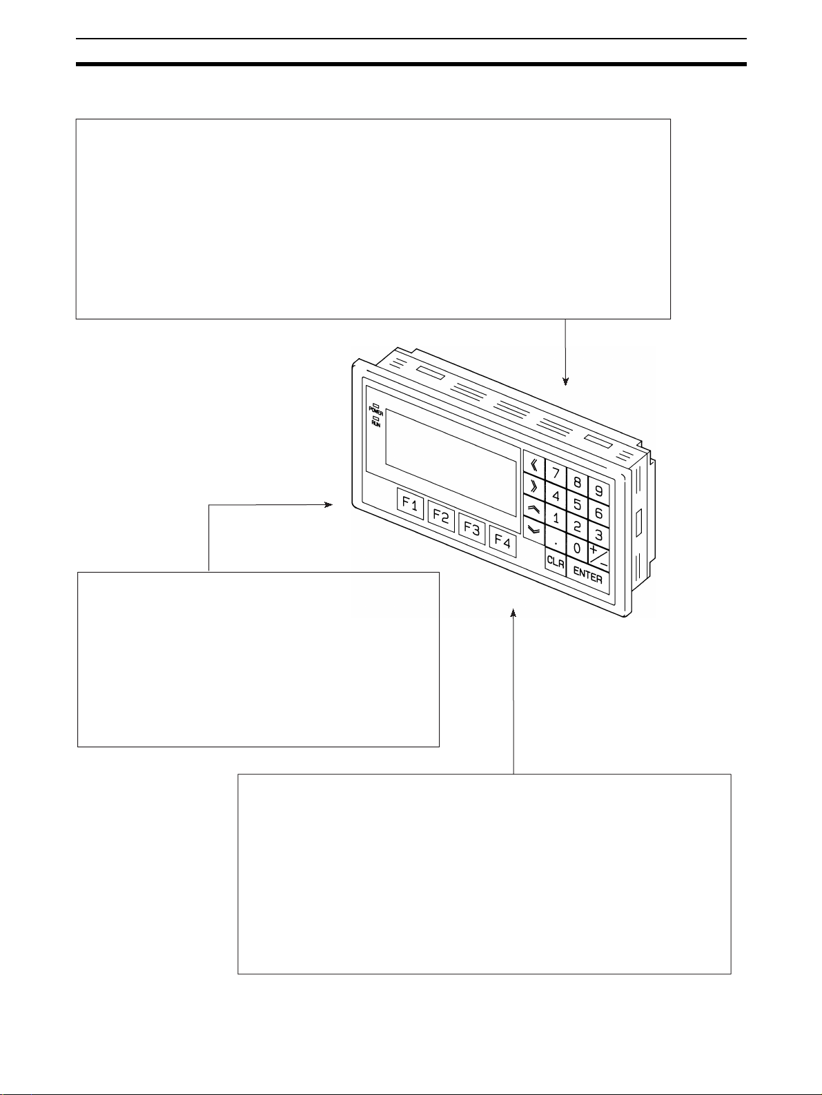
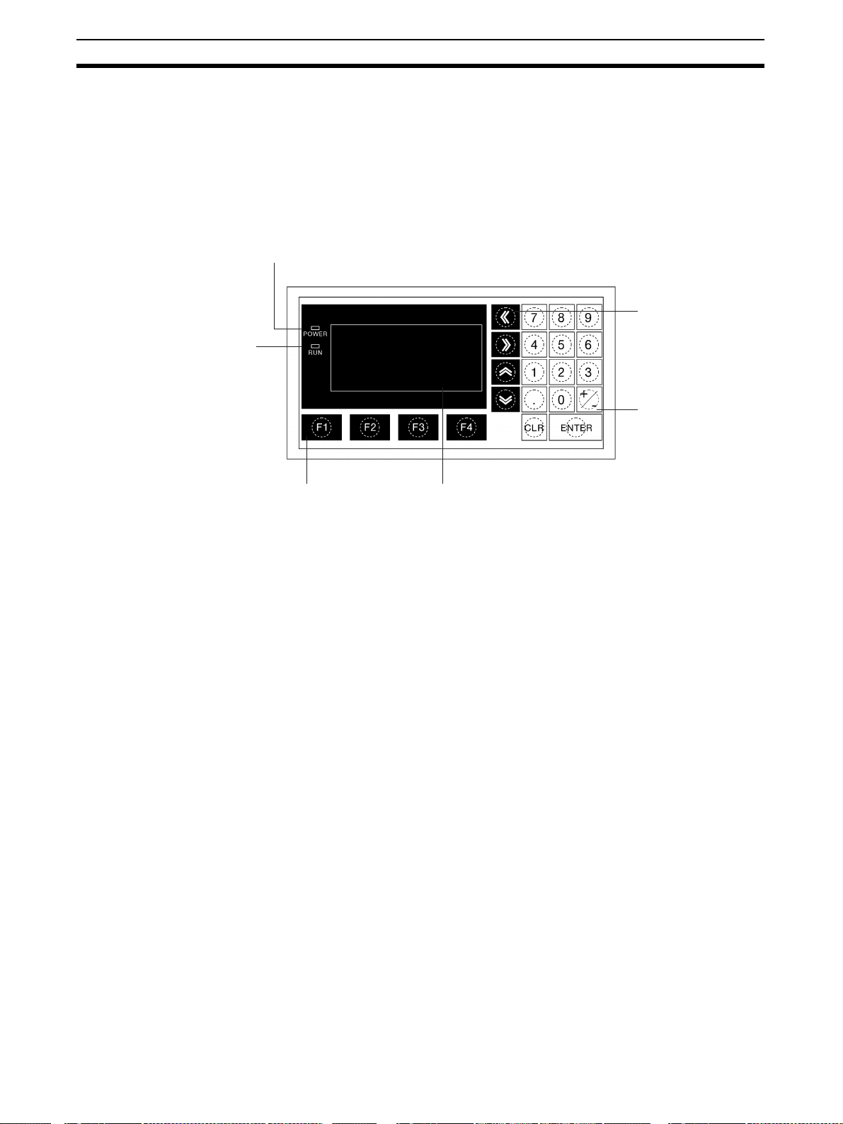
2-1-1 Description of Parts
Front View
POWER LED
Lit when the
power is supplied.
Arrow keys
Used to select the
RUN LED
Lit when the
communication
status is normal.
required numerical
value input field when
there is more than one
on the screen.
Numeric keys
Used for inputting
numerical values on
screens that require
numerical value input.
Function keys
Used for direct
notifications to the PLC.
Display
An LCD screen with a backlight.
Reference The NT11 comes in two body colors.
• NT11-SF121-EV1:Beige
• NT11-SF121B-EV1:Black
16
Page 30
Description of Parts and Settings Section 2-1
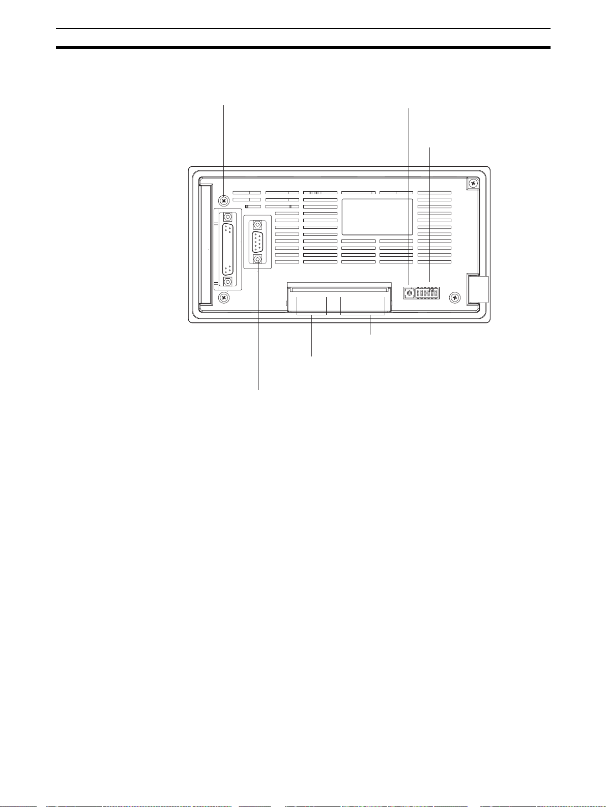
Rear View
Connector for parallel interface connection
Connect the printer cable here.
(Interface conforms to Centronics specifications)
Contrast control
Use a fine phillips screwdriver.
Turn clockwise to increase the brightness.
DIP switch
Set various system statuses
with these switches.
RS-422A terminal block
Connect the PLC cable here.
Power input terminals
Connect the power to the
NT11 at these terminals.
RS-232C connector
Connect the cable that connects
the PLC or support tool here.
17
Page 31

Description of Parts and Settings Section 2-1
2-1-2 DIP Switch Settings
Set the NT11 operation status with the DIP switches located in the bottom
right corner on the rear side of the body.
DIP Switch Settings Factory setting: ALL OFF
DIP Switch Pin Function
SW1 1 RS-422A terminating resistance used
0 Not used
SW2 1 Screen data forced initialize effective
0 Ineffective
SW3 1 Emergency transfer mode
0 Ineffective
SW4 1 Switching to the System Menu disabled
0Enabled
SW5 Reserved.
SW6 1 System program erase enabled
0Disabled
Emergency transfer mode: When power to the NT11 is turned ON with DIP
switch pin 3 turned ON, data transfer mode will be
entered directly without any other operation.
!Caution In addition to the DIP switches, set also the “Comm. Method”, “Host Link
Speed”, “Automatic Reset”, etc. at the memory switches. For these settings,
refer to 3-7 Setting the Conditions of Communications with the PLC by Using
the Memory Switches (page 71).
!Caution After changing the switch settings, always press the reset switch or turn the
power off and back on.
Otherwise the system will not operate as expected.
!Caution Confirm system safety before turning the power ON/OFF or resetting.
Otherwise the system may operate unpredictably.
Correct Use Use the “System program erase” function only when changing the system
program.
It the system program is erased, it will not be possible to use the functions of
the NT11 unless another system program is transferred.
18
Page 32

Installation Section 2-2
If the DIP switch settings have been changed when the NT11 is powered,
reset the power to the NT11. The changes with the DIP switches become
effective only after the power supply is reset.
2-2 Installation
Install the NT11 to the operation panel and connect the power to the NT11 as
described below.
1. Do not install the unit at sites subject to the following conditions.
Otherwise, the product may malfunction.
• Severe temperature variations
• Temperature or humidity outside the ranges stated in the specifications
• High humidity, condensation
• Splashing chemical agents
• Severe oil splashing
• Corrosive or flammable gases
• Strong vibrations or shocks
• Direct exposure to wind and rain (outdoor sites)
• Strong ultra-violet irradiation
2. Take adequate measures to ensure shielding if the unit is used at a location subject to any of the following conditions. Otherwise, the product may
malfunction.
• Static electricity, or noise from other equipment
• Strong electromagnetic fields
• Nearby power cables
• Potential exposure to radioactivity
2-2-1 Installation to the Operation Panel
The NT11 can be flush mounted to an operation panel.
Use the panel fittings and tools included in the product package and follow the
procedure below.
!Caution On unpacking the unit, check its external appearance and confirm that there is
no damage. Also confirm that there is no abnormal noise on shaking the unit
lightly. The product may malfunction if it is damaged.
!Caution During work at the panel, take care to ensure that no metal scraps enter the
unit.
Otherwise, the product may malfunction.
!Caution The thickness of applicable operation panel is 1.6 mm to 4.8 mm. All fittings
must be tightened uniformly to a torque of 0.5 to 0.6 N·m in order to ensure
water- and dust-resistance. The panel must not be soiled or warped, and must
be able to support an installation that will remain secure and strong.
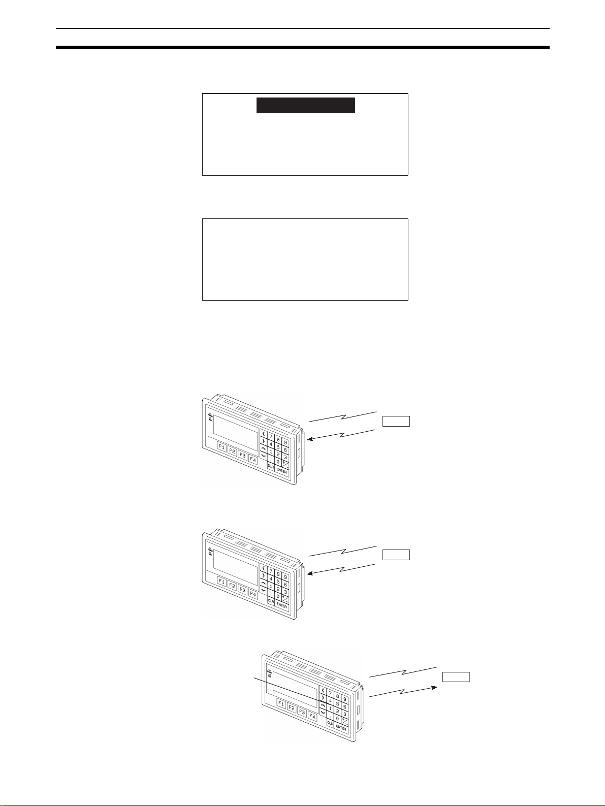
1,2,3... 1. Open a hole, shown below, in the panel and install the NT11 from the front
side of the panel.
19
Page 33

Installation Section 2-2
+0.5 mm
98.8
0 mm
+0.5 mm
204.2
0 mm
2. Attach the panel fittings at four positions for the upper/lower sides and at
two positions for the right and left sides, shown below, on the rear side of
the NT11.
Fit the hook of the fitting in the square hole in the body and tighten the
screw with a Phillips head screwdriver while lightly pulling the fitting.
2-2-2 Power Supply Connection
Connect a 24 VDC power supply to the power input terminals.
!Caution Carefully check the wiring before switching ON the power.
!Caution Do not connect AC power to the DC terminals.
!Caution Use DC and AC power supplies with low voltage and frequency fluctuations.
!Caution Do not perform withstand voltage test. Performing withstand voltage test may
result in malfunction.
0 V 24 V
+
• Noise prevention
The NT11 has a noise preventive feature against the power supply line
noise. To further reduce noise, connect a noise filter to the power line.
This will drastically reduce the ground noise.
Breaker
24 VDC Power Supply
20
Page 34

Installation Section 2-2
• Power supply
Applicable power supply specifications are as follows.
Item Value
Power supply voltage 24 VDC
Allowable power supply voltage
fluctuation range
Power supply capacity 10 W or lower
• Parts used for connection
Use crimp terminals to connect the power supply to the power input terminals. Recommended crimp terminals for M3.5 are given below.
20.4 VDC to 26.4 VDC
(24 VDC –15%, +15%)
!Caution For the connection to the power supply terminal block, twisted wires of 2 mm
or greater cross sectional area and M 3.5 size crimp terminals must be used.
Tighten the screws on the terminal block to a torque of 0.5 N
×m.
Otherwise fire may occur.
Fork type Round type
7 mm or less
7 mm or less
[Recommended terminals]
Maker Type
(fork type)
Japan Solderless Terminal MFG 2-YS3A 2-3.5
Fuji Terminal 2-YAS3.5 V2-S3.5
Nichifu Terminal 2Y-3.5 2-3.5
Type
(round type)
Applicable Wire
(stranded wire)
1.04 to 2.63 mm
2
Note When surge noise occurs in the DC power supply, connect a Transistor Volt-
age Suppressor (TVS) between the 24-V and 0-VDC terminals.
Recommended TVS model: 1.5KE33CA
Manufacturers: Vishay Intertechnology Inc, STMicroelectronics
24 VDC
2
2-2-3 Wiring the Ground Wire
The PT is provided with a functional ground (FG: ) terminal.
Wire the FG terminal according to the following conditions.
1. Ground according to Figure when there is difference in potential between
the PT and host. Do not ground the functional ground of the PT if it is far
from the host and one-point grounding is difficult.
2. Do not ground the functional ground (FG: ) of the PT if it is mounted to
the same panel as devices that generate noise, such as motors and inverters.
TVS
21
Page 35

Connecting to the NT Support Tool Section 2-3
PT Host
One-point
grounding
Note Ground correctly to prevent malfunctions caused by noise.
2-3 Connecting to the NT Support Tool
In order to install the system program in the NT11, or to transmit screen data
created with the NT Support Tool to the NT11, the NT11 must be connected to
a personal computer with an RS-232C cable.
The NT11 connects with the RS-232C cable from a personal computer at the
RS-232C serial port.
Serial port A
(RS-232C, 9-pin)
Communication Conditions
The communication conditions are automatically set when the system installer
and NT Support Tool are started.
Recommended Connector Cable
Use the cable indicated below.
• XW2Z-S002 (length: 2 m), made by OMRON
(D-SUB 9-pin, male Û D-SUB 9-pin, female)
For details on making a connector cable, refer to Appendix E Making the
Cable for Connecting a Personal Computer (page 155).
2-4 Connection to a PLC by the Host Link (RS-232C Type)
Connect the NT11 to an OMRON PLC by using RS-232C type the host link
method.
In order to make a connection to the PLC using the host link method (RS232C type), the “Comm. Type” memory switch of the NT11 must be set to
“host link”, and the “Comm. Port” memory switch must be set to “RS-232C”.
For details on memory switch settings, refer to 3-7-1 Selecting the Host Com-
munication Method (page 73).
22
Page 36

Connection to a PLC by the Host Link (RS-232C Type) Section 2-4
2-4-1 Compatible PLCs
Some models and series of OMRON PLCs have the host link function built in.
Check the model and series of the PLC against the type of host link unit
before making the connections.
The compatible PLCs are listed in the table below.
PLC
Series
CS Series CS1G-CPU42/43/44/45-EV1
CJ Series CJ1G-CPU44/45 CJ1G-CPU44/45 CJ1W-SCU41 CJ1G
C Series --- C200HS-CPU01/03/21/23/31/
CVM1
Series (*3)
CompoBus/S
Master
Unit
Units with Built-in Host Link
Function
CS1H-CPU63/64/65/66/67-EV1
CS1G-CPU42H/43H/44H/45H
CS1H-CPU63H/64H/65H/66H/
67H
C200HS-CPU21/23/31/33-E --- --- C200HS
C200HE-CPU42-E
C20HE-CPU42-ZE
C200HG-CPU43/63-E
C200HG-CPU43/63-ZE
C200HX-CPU44/64-E
C200HX-CPU44/64/65/85-ZE
CPM1-10/20/30CDR-@
+CPM1-CIF01
CPM1A-10/20/30/40CD@-@
+CPM1-CIF01
CPM2A-30/40/60CD@@-@
+CPM1-CIF01
(Peripheral port connection)
CPM2C-10/20@@@@@@-@
(*1)
CQM1-CPU21-E
CQM1-CPU41/42/43/44-EV1
CQM1H-CPU11/21/51/61 (*2) CQM1H-CPU51/61 CQM1H-SCB41 CQM1H
CVM1-CPU01-EV2
CVM1-CPU11-EV2
CVM1-CPU21-EV2
SRM1-C02-V1 --- --- SRM1
CPU Units Connectable with
Host Link Units or Expansion
Communication Board
CS1G-CPU42/43/44/45-EV1
CS1H-CPU63/64/65/66/67-EV1
CS1G-CPU42H/43H/44H/45H
CS1H-CPU63H/64H/65H/66H/
67H
33-E
C200HE-CPU11/32/42-E
C200HE-CPU11/32/42-ZE
C200HG-CPU33/43/53/63-E
C200HG-CPU33/43/53/63-ZE
C200HX-CPU34/44/54/64-E
C200HX-CPU34/44/54/64/65/
85-ZE
C200HE-CPU32/42-E
C200HE-CPU32/42-ZE
C200HG-CPU33/43/53/63-E
C200HG-CPU33/43/53/63-ZE
C200HX-CPU34/44/54/64-E
C200HX-CPU34/44/54/64/65/
85-ZE
--- --- CPM1
--- ---
--- --- CPM2A
--- --- CPM2C
--- --- CQM1
CVM1-CPU01-EV2
CVM1-CPU11-EV2
CVM1-CPU21-EV2
Host Link Unit/
Communication
Board
CS1W-SCU21
CS1W-SCB21
CS1W-SCB41
C200H-LK201-EV1 C200HS
C200HW-COM02/04/
05/06-EV1
CV500-LK201 CVM1
Connectable
CS1G
CS1H
CS1G-H
CS1H-H
C200HE
C200HE-Z
C200HG
C200HG-Z
C200HX
C200HX-Z
C200HE
C200HE-Z
C200HG
C200HG-Z
C200HX
C200HX-Z
to
*1: Use a CPM2C-CN111 or CS1W-CN114/118 Connecting Cable, CPM1-CIF01 RS-232C Adapter, or CPM1-
CIF11 RS-422A Adapter to connect.
23
Page 37

Connection to a PLC by the Host Link (RS-232C Type) Section 2-4
*2: The CQM1H-CPU11 does not have a built-in RS-232C port, so connect to the PT at the peripheral port
with a CS1W-CN118 Connecting Cable.
*3: CPU Units of CVM1/CV-series PLCs without the suffix -EV@ cannot be connected.
2-4-2 Connecting the NT11
Refer to the illustrations below to select the appropriate cable for the unit connectors and connect the NT11 to the PLC.
To make a connector cable, refer to Appendix D Making the Cable (page 153).
!Caution Before inserting or removing the connectors, make sure that the NT11 and the
PLC are turned OFF.
!Caution After connecting a communication cable, always secure it with the screws.
Otherwise the cable may disconnect, causing operation to fail.
!Caution The cable’s tensile load is 30 N. Do not subject it to loads greater than this.
Otherwise a discontinuity may occur, causing operation to fail.
Connecting to a PLC with a 25-pin Connector
Use a connector cable with a 25-pin connector on one end and a 9-pin connector on the other end (NT11 side) to connect the NT11 to a PLC with a 25pin connector.
Host I/F connector
(RS-232C 9-pin type)
9-pin connector 25-pin connector
Connecting to a PLC with a 9-pin Connector
Use a connector cable with a 9-pin connector on both ends to connect the
NT11 to a PLC with a 9-pin connector.
Host I/F connector
(RS-232C 9-pin type)
9-pin connector
The method for connection between the RS-232C ports of the NT11 and the
host is described here.
NT11
NT11
RS-232C connector cable
RS-232C connector cable
Host link unit/CPU unit
Host link unit/CPU unit
9-pin connector
C200H,
C200HS
C200H,
C200HS
24
Recommended Connector Cable
When making the connector cable, as far as possible use the recommended
connectors, connector hoods, and cables indicated in the table below. Some
Units come supplied with one connector and one connector hood.
Page 38

Connection to a PLC by the Host Link (RS-232C Type) Section 2-4
Check the required components and prepare them in advance.
Name Model Remarks Delivered with
CS-series CS1G/CS1H,
CS1G-H/CS1H-H
CJ-series CJ1G
Connector
Connector
hood
Connector
set
Cable
XM2A-0901
XM24-2501
XM2S-0911
XM2S-0913
XM2S-0911-E
XM2S-2511
XM2S-0911S003
AWG28´5P
IFVV-SB
CO-MA-VV-SB
5P´28AWG
9-pin
Made by OMRON
25-pin
Made by OMRON
9-pin
Made by OMRON
9-pin
Made by OMRON
9-pin
Made by OMRON
25-pin
Made by OMRON
9-pin
Made by OMRON, connector and hood included
Multi-core shielded cable
Made by Fujikura, Ltd.
Multi-core shielded cable
Made by Hitachi Cable,
Ltd.
C-series CQM1, C200HS,
C200HX/HG/HE(-Z)E,
CVM1/CV-series CPU
Units
CV500-LK201
CV500-LK201
C200H-LK201-EV1
C-series CQM1, C200HS,
C200HX/HG/HE-(Z)E,
CVM1/CV-series CPU
Units
CV500-LK201
---
CS-series CS1G/CS1H,
CS1G-H/CS1H-H
CJ-series CJ1G
CV500-LK201
C200H-LK201-EV1
---
---
---
Note After connecting a communication cable, always secure it with the screws.
Note The cable’s tensile load is 30 N. Do not subject it to loads greater than this.
Wiring for a Host Link Unit
(25-pin) Connection
Otherwise the cable may disconnect, causing operation to fail.
OMRON Cables with Connectors
The OMRON cables listed below can be used when connecting with a method
other than the memory link method.
Model Cable Length Connector Specification
XW2Z-200S 2 m
XW2Z-500S 5 m
XW2Z-200T 2 m
XW2Z-500T 5 m
9-pin Û 25 pin
9-pin Û 9-pin
Otherwise a discontinuity may occur, causing operation to fail.
Applicable Units: C200H-LK201-EV1
CV500-LK201 (communication port 1)
Compatible cables with attached connectors:
XW2Z-200S (9-pin
XW2Z-500S (9-pin
Û 25-pin, 2 m)
Û 25-pin, 5 m)
25
Page 39

Connection to a PLC by the Host Link (RS-232C Type) Section 2-4
CVM1/CV-series Host Link Units (CV500-LK201) have two types of connector; a 25-pin connector (communication port 1), and a 9-pin connector (communication port 2). When using communication port 2, refer to Wiring for
Other Connections (Other Than the Memory Link Method) (page 26).
1
5
Wiring for Other
Connections
6
9
NT11
RS-232C
interface
(9-pin type)
Abbreviation
FG
SD
RD
RS
CS
+5V
5G
Pin
number
Connector
hood
1
2
3
4
5
6
7
8
9
Shield
PLC (Host Link Unit)
Pin
Abbreviation
number
Connector
FG
hood
2
SD
3
RD
4
RS
5
CS
6
*
-
7
5G
8
-
-
-
-
-
-
-
-
ER
RS-232C
interface
114
(25-pin type)
13 25
* For Units that have a CTS setting selector switch, RS and CS do not have to
be shorted if this switch is set to 0 V.
Applicable Units:
CV500-LK201 (communication port 2)
CS1W-SCU21 CJ1W-SCU41
CPM1-10CDR-@ CPM1-20CDR-@
CPM1-30CDR-@
CPM1A-10CD@-@ CPM1A-20CD@-@
CPM1A-30CD@-@ CPM1A-40CD@-@
CPM2A-30CD@-@ CPM2A-40CD@-@
CPM2A-60CD@-@
CPM2C-10@@@@@@-@ CPM2C-20@@@@@@-@
CQM1-CPU21-E
CQM1-CPU41-EV1 CQM1-CPU42-EV1
CQM1-CPU43-EV1 CQM1-CPU44-EV1
CQM1H-CPU11 CQM1H-CPU21
CQM1H-CPU51 CQM1H-CPU61
CS1G-CPU42-E(V1) CS1G-CPU43-E(V1)
CS1G-CPU44-E(V1) CS1G-CPU45-E(V1)
CS1H-CPU63-E(V1) CS1H-CPU64-E(V1)
CS1H-CPU65-E(V1) CS1H-CPU66-E(V1)
CS1H-CPU67-E(V1)
CS1G-CPU42H CS1G-CPU43H
CS1G-CPU44H CS1G-CPU45H
CS1H-CPU63H CS1H-CPU64H
CS1H-CPU65H CS1H-CPU66H
CS1HCPU67H
CJ1G-CPU44 CJ1G-CPU45
C200HS-CPU21-E, -EC C200HS-CPU23-E
C200HS-CPU31-E C200HS-CPU33-E
C200HE-CPU32-(Z)E C200HE-CPU42-(Z)E
C200HG-CPU33-(Z)E C200HG-CPU43-(Z)E
C200HG-CPU53-(Z)E C200HG-CPU63-(Z)E
C200HX-CPU34-(Z)E C200HX-CPU44-(Z)E
26
Page 40

Connection to a PLC by the Host Link (RS-232C Type) Section 2-4
C200HX-CPU54-(Z)E C200HX-CPU64-(Z)E
C200HX-CPU65-ZE C200HX-CPU85-ZE
CVM1-CPU01-EV2 CVM1-CPU11-EV2
CVM1-CPU21-EV2
SRM1-C02-V2
Compatible cables with attached connectors:
XW2Z-200T (9-pin
XW2Z-500T (9-pin
CPU Units of CVM1/CV-series PLCs without the suffix -EV@ cannot be connected by any connection method.
Û 9-pin, 2 m)
Û 9-pin, 5 m)
1
5
6
9
NT11 PLC (Host Link Unit)
Abbreviation
FG
-
SD
RD
RS-232C
RS
interface
CS
+5V
−
−
SG
(9-pin type)
2-4-3 PLC Switch Settings
When the NT11 and PLC are connected to each other, set the conditions at
the PLC host link unit or the CPU as given in the table below.
The following is a general description of switch settings.
Refer to the manual for respective units for the details of the switch settings.
I/O port RS-232C
Baud rate Set the same baud rate as the NT11. (*1)
Transfer code ASCII 7 data bits, 2 stop bits
Parity Even
1-to-1/1-to-N 1-to-N (*2)
Instruction level Level 1, 2, 3
Unit No. 00
1
Pin
number
Connector
hood
1
2
3
4
5
6
7
8
9
Shield
*
Pin
number
Connector
hood
2
3
4
5
6
7
8
9
(9-pin type)
Abbreviation
FG
SD
RD
RS
CS
−
−
−
SG
RS-232C
interface
5
Item Switch Setting
6
9
*1 Set the host link baud rate up to 115,200 bps with the memory switch for
“host link baud rate”. For the details, refer to 3-7-2 Selecting the Host Link
Communication Speed (page 74).
*2 The 1-to-N setting enables BCC (Block Check Character). The 1-to-1 con-
nection cannot be used to connect the NT11 to a host link unit.
27
Page 41

Connection to a PLC by the Host Link (RS-232C Type) Section 2-4
Connecting to a C-series Host Link Unit
C200H/C200HS/C200HE/HG/HX (-Z)E Rack-mounted Unit:
C200H-LK201-V1
Setting the Front Switches
Set each switch with a flat blade screwdriver so that the values or symbols in
the setting value window agree with the following.
LK201
RUN
RCV
SW1
SW3
XMT
ERROR
SW2
0
0
SW4
2
5
•
Unit # (SW1, SW2)
Set these switches to 0.
•
Command level, parity, and transfer code (SW4)
Set this switch to 2.
• Baud rate (SW3)
Set this switch to 5 to select 9,600 bps.
Set this switch to 6 to select 19,200 bps.
Setting the Rear Switches
ON
1
2
3
CTS selector switch
External
0 V (ON)
4
• 1-to-1/1-to-N selection (DIP switch)
Set pin 3 to ON.
• CTS selection (selector switch)
Set this always to 0 V (ON).
Connecting to a CVM1/CV-series Host Link Unit
CVM1/CV-series Rack-mounted Unit: CV500-LK201
A CVM1/CV-series Host Link Unit (CV500-LK201) has two connectors (communication ports 1 and 2). Either of these ports can be used for connection to
an NT11 by the RS-232C method. However, since the connectors at these
ports are of different types, a cable that matches the connector must be prepared.
• Communication port 1
Communication port 1 is a 25-pin connector for RS-232C use only.
• Communication port 2
Communication port 2 is a 9-pin connector that allows selection of the
RS-232C or RS-422A method. When this port is used with the RS-232C
method, the I/O port selector switch on the front of the Unit must be set to
RS-232C (the upper position).
28
Page 42

Connection to a PLC by the Host Link (RS-232C Type) Section 2-4
CPU Bus Unit Settings
When connecting to a CVM1/CV-series Host Link Unit, set the following communication conditions for the CPU Bus Unit settings.
Item Setting at Host
Baud rate
Set the same baud rate as set at the NT11
Transfer code ASCII, 7 data bits, 2 stop bits
Parity Even
1-to-1, 1-to-N
1-to-N
(*2)
Command level Level 1, 2, 3
*1 Set the Host Link baud rate up to 115,200 bps with the memory switch at
the NT11. For details, refer to Setting the Host Link Method (page 74).
*2 The 1-to-N setting enables BCC (Block Check Character). It is not actually
possible to connect more than one NT11 in a single Host Link.
Set the CPU Bus Unit settings directly from a Programming Device (e.g.,
SYSMAC Support Software).
For details on the CPU Bus Unit settings, refer to the SYSMAC CVM1/CV-
series Host Link Unit Operation Manual (W205-E1-@).
Setting the Front Switches
(*1)
Communications port 1
(RS-232C)
Communications port 2
(RS-232C/RS-422A)
I/O port selector switch
RS-232C
RS-422A
Connecting to a CS/CJ-series Serial Communications Unit
CS/CJ-series Rack-mounted Unit: CS1W-SCU21CJ-series:
CJ1W-SCU41 (Port 2 is an RS-232C Port.)
• Unit # (SW3, SW4)
When using communication port 2, set these
switches to 0.
• I/O port selection (selector switch)
Set this to RS-232C.
• CTS selection (Pins 2 and 3)
Set pin 2 or 3 to ON. (Set this always to 0 V.)
To use communication port 1, turn ON pin 2.
To use communication port 2, turn ON pin 3.
• Communication condition setting (Pin 1)
Set this pin to OFF.
Communication is executed in accordance with the
CPU Bus Unit system settings made at the PLC. The
initial values for the system settings are as follows.
- Baud rate: 9,600 bps
- Parity: Even
- Xon/Xoff control: Not executed
- Communication method: Full duplex
- Stop bits: 2 stop bits
- Data length: 7 bits
Setting the Front Switches
Set the unit number of the Serial Communications Unit by using the rotary
switch located on the front panel. Set each switch with a flat blade screwdriver
29
Page 43

Connection to a PLC by the Host Link (RS-232C Type) Section 2-4
so that the values or symbols in the setting value window agree with the following.
CS1W-SCU21
SCU21
RUN
ERC
SD1
RD1
CJ1W-SCU41
Allocation DM Area Settings for CPU Unit
Settings are written from the Programming Device (a Programming Console
or CX-Programmer) directly into the allocated DM Area (PLC Setup) of the
CPU Unit. After the settings are written, they become effective by turning the
power ON, restarting the Unit, restarting the communication port, or execution
of the STUP instruction.
The following table shows the words allocated in the DM Area and the settings.
m = DM30000 + 100
RDY
ERH
SD2
RD2
UNIT
F
0
E
1
No.
C
´ unit number
Set the unit number to 0 through F so
that it will not duplicate the numbers
used in other Units.
Set the unit number to 0 through F so
that it will not duplicate the numbers
used in other Units.
Allocated DM word Value Settings
Port 1 Port 2
m m+10 8000 Host Link mode, 2 stop bits, even parity, data
length 7 bits
m+1 m+11 0000 Baud rate 9,600 bps
0007 Baud rate 19,200 bps
0008 Baud rate 38,400 bps
0009 Baud rate 57,600 bps
000A Baud rate 115,200 bps
m+2 m+12 0000 Transmit delay time 0 ms
m+3 m+13 0000 No CTS control Unit No. 0 for Host Link
Connecting to a CPU Unit CV-series and CVM1/CV-series (-EV
CVM1-CPU01-EV2/CVM1-CPU11-EV2/CVM1-CPU21-EV2
PLC Setup
When connecting to a CVM1/CV-series CPU Unit, set the following communication conditions for the PLC Setup.
Item Setting at Host
Baud rate
Stop bits 2 stop bits
Parity Even
Data length ASCII 7 bits
Unit # 00
Set the same baud rate as set at the NT11
@) CPU Units
(*1)
30
*1 Set the Host Link baud rate at 9,600 bps with the memory switch at the
NT11. For details, refer to Setting the Host Link Method (page 74).
Page 44

Connection to a PLC by the Host Link (RS-232C Type) Section 2-4
Either set PLC Setup directly from a Programming Device (e.g., SYSMAC
Support Software), or transmit the PLC Setup made at a Programming Device
to the CPU Unit.
For details on the PLC Setup, refer to the SYSMAC CVM1/CV500/1000/2000
Operation Manual: Ladder Diagrams (W202-E1-@).
Setting the Front Switches
• Host Link Communication method
(selector switch)
Set this to RS-232C.
• System setting (Pin 4)
To effect the existing DIP switch settings,
set SW4 to ON.
To effect the existing PLC Setup, set pin 4
I/O port selector switch
RS-232C
RS-422A
to OFF.
Note
For CPU Units manufactured before or
during June 1995 (lot No. @@65), the
existing DIP switch settings differ from
the existing PLC Setup as follows.
- DIP switch settings:
2,400 bps, 1 stop bit, even parity, 7 bit
data length
- PLC Setup:
9,600 bps, 2 stop bits, even parity, 7 bit
data length
For CPU Units manufactured from July
1995 onward (lot No. @@75), the
stipulated values in the DIP switch
settings also are 9,600 bps and 2 stop
bits.
C-series C200HS, C200HX/HG/HE(-Z)E, CPM1, CPM2A, CPM2C, CQM1,
CQM1H CPU Units and SRM1
The connection method depends upon the model of PLC being used, as
shown in the following table.
PLC model Connection method
C200HS, CQM1 Connect to the CPU Unit’s built-in RS-232C port.
C200HX/HG/HE(-Z)E • Connect to the CPU Unit’s built-in RS-232C port.
• Connect to one of the RS-232C ports (port A or port B) on
a Serial Communications Board.
CQM1H • Connect to the CPU Unit’s built-in RS-232C port.
• Connect to the peripheral port through a CS1W-CN118
Connecting Cable.
• Connect to the RS-232C port (port 1) on a Serial Communications Board.
CPM1 Connect to the peripheral port through a CPM1-CIF01 RS-
232C Adapter.
31
Page 45

Connection to a PLC by the Host Link (RS-232C Type) Section 2-4
PLC model Connection method
CPM2A, SRM1 • Connect to the CPU Unit’s built-in RS-232C port.
• Connect to the peripheral port through a CPM1-CIF01 RS232C Adapter.
CPM2C Connect to the CPU Unit’s RS-232C port or the peripheral
PLC Setup Settings
When connecting to a C200HS, C200HX/HG/HE(-Z)E, CPM1, CPM2A,
CPM2C, CQM1, or CQM1H CPU Unit, or SRM1, set the following communication conditions for the PLC Setup.
Item Setting at Host
Communication mode Host Link mode
Baud rate
Stop bits 2 stop bits
Parity Even
Data length ASCII 7 bits
Unit # 00
port through a Connecting Cable (CPM2C-CN111, CS1WCN118, or CS1W-CN114).
(The CPM2C-CN111 splits the Unit’s Communication Port
into a RS-232C port and a peripheral port. A CPM1-CIF01
RS-232C Adapter is also required to connect to this peripheral port.)
Set the same speed as set at the NT11
(*1)
*1 Set the Host Link baud rate at 9,600 bps or 19,200 bps with the memory
switch at the NT11. For details, refer to Settings the Host Link Method
(page 74).
Set the PLC Setup settings directly from a Programming Device (e.g., the CXProgrammer Support Software).
For details on operations relating to the PLC Setup, refer to the manual for the
PLC which is used.
The PLC Setup area word addresses and settings to be made depending on
the Unit and port to which the connection is made are shown below.
CPM2A, CPM2C, CQM1H, or SRM1: Peripheral port connection
Word Writing Value Settings
DM6650 0001 Host Link mode, no CTS control
Communication conditions set by the contents of DM
DM6651 0303 Data length 7 bits, 2 stop bits, even parity, baud rate:
9,600 bps
0304 Data length 7 bits, 2 stop bits, even parity, baud rate:
19,200 bps
DM6653 0000 Unit # 00
32
Page 46

Connection to a PLC by the Host Link (RS-232C Type) Section 2-4
C200HS, C200HX/HG/HE(-Z)E, CPM2A, CPM2C, CQM1, CQM1H (other
than the CPU11), or SRM1: Built-in RS-232C port connection
Word Writing Value Settings
DM6645 0001 Host Link mode, no CTS control
Communication conditions set by the contents of DM
DM6646 0303 Data length 7 bits, 2 stop bits, even parity, baud rate:
9,600 bps
0304 Data length 7 bits, 2 stop bits, even parity, baud rate:
DM6648 0000 Unit # 00
C200HX/HG/HE(-Z)E: Serial Communications Board port A
CQM1H: Serial Communications Board port 1
Word Writing Value Settings
DM6555 0001 Host Link mode, no CTS control
DM6556 0303 Data length 7 bits, 2 stop bits, even parity, baud rate:
0304 Data length 7 bits, 2 stop bits, even parity, baud rate:
DM6558 0000 Unit # 00
19,200 bps
Communication conditions set by the contents of DM
9,600 bps
19,200 bps
C200HX/HG/HE(Z)E: Serial Communications Board port B
Word Writing Value Settings
DM6550 0001 Host Link mode, no CTS control
Communication conditions set by the contents of DM
DM6551 0303 Data length 7 bits, 2 stop bits, even parity, baud rate:
0304 Data length 7 bits, 2 stop bits, even parity, baud rate:
DM6553 0000 Unit # 00
9,600 bps
19,200 bps
CPM1: Peripheral port connection through a CPM1-CIF01 RS-232C Adapter
Word Writing Value Settings
DM6650 0001 Host Link mode
Communication conditions set by the contents of DM
DM6651 0303 Data length 7 bits, 2 stop bits, even parity, baud rate:
0304 Data length 7 bits, 2 stop bits, even parity, baud rate:
DM6653 0000 Unit # 00
9,600 bps
19,200 bps
Connecting to a CPM2C
The CPM2C PLCs do not have the same kind of port connectors found on
CS1-series PLCs. The CPM2C’s communication port handles both RS-232C
and peripheral port connections, which are divided internally. Therefore, when
using the CPM2C, it is necessary to select RS-232C or peripheral port connections, according to the kind of cable and port (on the cable) used, as
shown in the following table. Refer to the CPM2C Operation Manual for more
details.
33
Page 47

Connection to a PLC by the Host Link (RS-232C Type) Section 2-4
Port connecting to PT PLC Setup
RS-232C port (D-Sub 9-pin) of CPM2C-CN111 Built-in RS-232C port settings
Peripheral port of CPM2C-CN111 Peripheral port settings
RS-232C port (D-Sub 9-pin) of CS1W-CN118 Built-in RS-232C port settings
Peripheral port of CS1W-CN114 Peripheral port settings
Peripheral port
CPM2C-CN111
CPM2C
CS1W-CN118
CPM2C
CS1W-CN114
CPM2C
RS-232C port
(D-Sub 9-pin, female)
RS-232C port
(D-Sub 9-pin, female)
Peripheral port
Setting the DIP Switches of a C200HX/HG/HE(-Z)E, CQM1, or CQM1H
When using a C200HX/HG/HE(-Z)E, CQM1, or CQM1H, the DIP switches on
the front panel must be set as shown below in order to make the settings in
the PLC Setup (in the DM Area) effective.
C200HX/HG/HE(-Z)E
RS-232C port communication condition setting
Set pin 5 to OFF to make the settings made in
PLC Setup effective.
CQM1 CQM1H
When using the CQM1H’s built-in peripheral port, turn ON SW7.
Setting the Switches of a CPM2A
When using a CPM2A, the switches on the front panel must be set as shown
below in order to make the PLC Setup settings effective.
34
Set the Communications
switch to OFF (down
position).
Setting the Switches of a CPM2C
When using a CPM2C, the switches on the front panel must be set as shown
below in order to make the PLC Setup settings effective.
Page 48

Connection to a PLC by the Host Link (RS-232C Type) Section 2-4
The settings for SW1 and SW2 depend upon the usage of the
peripheral port and RS-232C port.
• Connecting PT to peripheral port
• Connecting PT to built-in RS-232C port
(A device that requires non-standard communications settings
is connected to the peripheral port.)
SW1: OFF
SW2: ON
• Connecting PT to built-in RS-232C port
(A Programming Console is connected to the peripheral port.)
SW1: OFF
SW2: OFF
Setting the Switches on an RS-232C Adapter
When using a CPM1-CIF01 RS-232C Adapter, set the mode switch as shown
in the following diagram.
CPM1CIF01
Set the mode setting switch to HOST (upper position).
CPM1
CS/CJ-series CPU Unit model: CS1G/HCPU
@@-E (-V1)
CS1G/H-CPU@@H
CJ1G-CPU@@
Connect to the built-in RS-232C port of the CPU Unit, or the RS-232C port of
the Communication Board. Note that the connection to a peripheral port must
be made via an RS-232C Adapter (CS1W-CN118) specially designed for connecting to a peripheral port.
PLC Setup
When connecting to a CS/CJ-series CPU Unit, set the following communication conditions for the PLC Setup. Since the settings shown below are the
PLC default settings for the CPU Unit, no change to the PLC Setup is necessary as long as the baud rate is maintained at 9,600 bps.
Item Setting at Host
Baud rate
Stop bits 2 stop bits
Parity Even
Data length ASCII 7 bits
Unit No. for the Host Link 00
Set the same speed as set at the NT11
(*1)
*1 Set the Host Link baud rate up to 115,200 bps with the memory switch at
the NT11. For details, refer to Settings the Host Link Method (page 74).
When the baud rate is set to 19,200 bps, the PLC Setup of the CPU Unit
need to be changed.
Either set the PLC Setup directly from a Programming Device (Programming
Console), or transmit the PLC Setup made at a Programming Device (CXProgrammer) to the CPU Unit.
35
Page 49

Connection to a PLC by the Host Link (RS-232C Type) Section 2-4
For details on PLC Setup, refer to the SYSMAC CS Series Operation Manual
(W339-E1-@) or SYSMAC CJ Series Operation Manual (W393-E1-@).
When using the built-in RS-232C port of a CS1G/H, CS1G/H-H, or CJ1G
Word address Writing Value Settings
CIO 160 8000 Host Link mode, data length 7 bits,
2 stop bits, even parity
CIO 161 0000 Baud rate: 9,600 bps.
0007 Baud rate: 19,200 bps.
0008 Baud rate: 38,400 bps.
0009 Baud rate: 57,600 bps.
000A Baud rate: 115,200 bps.
CIO 166 0000 Unit #00
When using the peripheral port of a CS1G/H, CS1G/H-H, or CJ1G
Word address Writing Value Settings
CIO 144 8000 Host Link mode, data length 7 bits,
CIO 145 0000 Baud rate: 9,600 bps.
0007 Baud rate: 19,200 bps.
0008 Baud rate: 38,400 bps.
0009 Baud rate: 57,600 bps.
000A Baud rate: 115,200 bps.
CIO 150 0000 Unit #00
2 stop bits, even parity
36
Page 50

Connection to a PLC by the Host Link (RS-232C Type) Section 2-4
Setting the Front Switches
Set pins 4 and 5 of the CPU Unit DIP switch in accordance with the port that
the NT11 is connected to.
CS1G/H, CS1G/H-H
RUN
ERR/ALM
INH
PRPHL/COMM
SYSMAC CS1G
PROGRAMMABLE CONTROLLER
CPU42
DIP switches (inside the battery storage)
• Set pin 4 to ON (establishing communication in accordance with PLC Setup) when connecting the
NT11 to the peripheral port.
• Set pin 5 to OFF (establishing communication in accordance with PLC Setup) when connecting the
NT11 to the RS-232C port.
Peripheral port
This is used mainly for
connection to the
Programming Device.
(This also supports the
RS-232C Unit connection.)
RS-232C port
This is used mainly for
connection to the
RS-232C Unit.
(This also supports a
CX-Programmer
connection.)
MCPWR
OPEN
PERIPHERAL
PORT
OPEN
BUSY
Peripheral port
This is used mainly for connection
to the Programming Device.
(This also supports the RS-232C
Unit connection.)
CJ1G
DIP switches (inside the battery storage)
• Set pin 4 to ON (establishing communication in accordance with PLC Setup) when connecting the
NT11 to the peripheral port.
• Set pin 5 to OFF (establishing communication in accordance with PLC Setup) when connecting the
NT11 to the RS-232C port.
RS-232 port
This is used mainly for connection to the RS-232C
Unit.
(This also supports a CX-Programmer connection.)
Connecting to CS-series Serial Communications Board
Serial Communications Board equipped with a RS-232C port for CS-series
CPU Units: CS1W-SCB41/21
Allocation DM Area Settings for CPU Unit
Settings are written from the Programming Device (a Programming Console
or CX-Programmer) directly into the allocated DM Area (PLC Setup) of the
CPU Unit. After the settings are written, they become effective by turning the
power ON, restarting the Unit, restarting the communication port, or execution
of the STUP instruction.
37
Page 51

Connection to a PLC by the Host Link (RS-422A Type) Section 2-5
The following table shows the words allocated in the DM Area and the settings.
Allocated DM word Value Settings
Port 1 Port 2
DM32000 DM32010 8000 Host Link mode, 2 stop bits, even parity, data
DM32001 DM32011 0000 Baud rate 9,600 bps.
0007 Baud rate 19,200 bps.
0008 Baud rate: 38,400 bps.
0009 Baud rate: 57,600 bps.
000A Baud rate: 115,200 bps.
DM32002 DM32012 0000 Transmit delay time 0 ms.
DM32003 DM32013 0000 No CTS control Unit No. 0 for Host Link
length 7 bits
2-5 Connection to a PLC by the Host Link (RS-422A Type)
Connect the NT11 to an OMRON PLC by using the RS-422A type host link
method.
If the distance between the NT11 and the PLC is greater than 15 m, this
method should be used. The maximum distance over which a connection can
be made is 500 m.
when using the RS-422A method, the host computer and PLC are usually
connected in a 1 to N ratio (more than one PLC), but in the special case of the
connection between the NT11 and PLC, the ratio is 1 to 1.
In order to make a connection to the PLC using the host link method (RS422A type), the “Comm. Type” memory switch of the NT11 must be set to the
host link, and the “Comm. Port” memory switch must be set to RS-422A. For
details on memory switch settings, refer to 3-7-1 Selecting the Host Commu-
nication Method (page 73).
2-5-1 Compatible PLCs
When Using the Host Link Method
Compatible Host Units
Some models and series of OMRON PLCs have the RS-422A type Host Link
function built in. With a CS series, CJ series, and CQM1H Board or Unit, and
CQM1H, the Host Link method can be used by installing a Serial Communications Board. In addition, some C200HX/HG/HE(-Z)E devices have an integral
CPU Unit that can be connected in the Host Link method by installing a Serial
Communications Board.
With the CPM2A and CPM2C, an RS-422A type of 1:1 NT Link can be connected through a CPM1-CIF11 RS-422A Adapter.
Check the model and series of the PLC and the type of the installed Board or
Unit before making a connection.
38
Page 52

Connection to a PLC by the Host Link (RS-422A Type) Section 2-5
The following table lists the Units that are equipped with an RS-422A Host
Link function compatible with the NT11.
PLC
Series
CS Series CS1W-SCB41-E --- CS1G-CPU42/43/44/45-EV1
CJ Series CJ1W-SCU41 --- CJ1G-CPU44/45 CJ1G
C Series C200H-LK202-V1 --- C200HS-CPU01/03/21/23/31/
C200HW-COM03/06EV1
--- CPM1-10/20/30CDR-@
--- CPM2A-30/40/60CD@-@
---
CQM1H-SCB41 --- CQM1H-CPU51/61 CQM1H
CVM1
Series
SRM1 --- SRM1-C02-V1+CPM1-CIF11 --- SRM1
CV500-LK201 CVM1-CPU01-EV2
(*2)
Units with Built-in Host Link Function CPU Units Connectable with
Host Link Unit/
Serial
Communications
Board
--- C200HE-CPU32/42-E
+CPM1-CIF11
CPM1A-10/20/30/40CD@-@
+CPM1-CIF11
+CPM1-CIF11
(Peripheral port connection)
CPM2C-10/20@@@@@@-@
CVM1-CPU11-EV2
CVM1-CPU21-EV2
CPU Unit
Host Link Units or Expansion
Serial Communications Board
CS1H-CPU63/64/65/66/67-EV1
CS1G-CPU42H/43H/44H/45H
CS1H-CPU63H/64H/65H/66H/
67H
33-E
C200HS-CPU01/21-EC
C200HE-CPU11/32/42-E
C200HE-CPU11/32/42-ZE
C200HG-CPU33/43/53/63-E
C200HG-CPU33/43/53/63-ZE
C200HX-CPU34/44/54/64-E
C200HX-CPU34/44/54/64/65/
85-ZE
C200HE-CPU32/42-ZE
C200HG-CPU33/43/53/63-E
C200HG-CPU33/43/53/63-ZE
C200HX-CPU34/44/54/64-E
C200HX-CPU34/44/54/64/65/
85-ZE
--- CPM1
--- CPM2A
(*1)
--- CPM2C
CVM1-CPU01-EV2
CVM1-CPU11-EV2
CVM1-CPU21-EV2
Connectable
CS1G
CS1H
CS1G-H
CS1H-H
C200HS
C200HE
C200HE-ZE
C200HG
C200HG-ZE
C200HX
C200HX-ZE
C200HE
C200HE-ZE
C200HG
C200HG-ZE
C200HX
C200HX-ZE
CVM1
to
*1 Use a CPM2C-CN111 or CS1W-CN114/118 Connecting Cable, CPM1-CIF01 RS-232C Adapter, or CPM1-
CIF11 RS-422A Adapter to connect.
*2 CPU Units of CVM1/CV-series PLCs without the suffix -EV@ cannot be connected.
39
Page 53

Connection to a PLC by the Host Link (RS-422A Type) Section 2-5
2-5-2 Parts Required for Connection
The RS-422A cable used for RS-422A communications is not supplied by
OMRON. Make this cable in accordance with the environment (PLC used and
transmission distance between the NT11 and PLC).
One connector, one connector cover and one cable are required to make up a
connecting cable. One connector and one connector cover is supplied with
the PLC. However, a cable of the type recommended by OMRON must be
prepared.
For details on making the cable, refer to Appendix D Making the Cable
(page 153). The table below lists the components supplied with each unit and
the recommended cables.
Check the required parts and prepare them in advance.
Name Model Maker Remarks
Connector
set
Connector XM2A-0901 9-pin connector
Connector
hood
Connector
set
Cable TKVVBS4P-03 Tachii Electric Wire
Crimp terminals
XM2S-0911S003
XM2S-0911 9-pin connector
XM2S-0911S003
1.25-N3A
(fork type)
Y1.25-3.5L
(fork type)
OMRON 9-pin connector
Made by OMRON
Made by OMRON
9-pin
Made by OMRON,
connector and
hood included
Co., Ltd.
Japan Solderless
Terminal MFG
Molex Inc.
Connector and Connector hood
Recommended cable size:
AWG22 to 18
(0.3 to 0.75 mm
2
)
Note 1. Always use crimp terminals for wiring.
2. Before connecting or disconnecting cables between devices, make sure
that the power supply to all of the connected devices (NT11, PLC, etc.) is
OFF.
Examples of applicable terminals
6.2 mm or less
2-5-3 Method for Connection
For RS-422A type communication, an RS-422A cable is used as the transmission channel connecting the NT11 and PLC.
As shown in the figure below, the RS-422A cable is connected directly to the
NT11.
Fork type
Round type
6.2 mm or less
40
Page 54

Connection to a PLC by the Host Link (RS-422A Type) Section 2-5
g
NT11
RS-422A terminal
block
RS-422A connector cable
(max. cable len
th : 500 m)
Host link unit/CPU unit
C200H,
C200HS
9-pin connector
Reference Carry out class 3 grounding at the FG terminal of the PLC. For details, refer to
the manual for the PLC.
!Caution Switch off the NT11 power supply before connecting or disconnecting a con-
nector.
2-5-4 Connector Specifications and Wiring for Each Unit
The combination of pin numbers to which the connecting wires are connected
differs according to the connector specifications for each unit. Check the connector specifications of the unit to be connected and make the wiring connections by referring to the relevant connection combination among those
indicated below.
For details on making the cable, refer to Appendix D Making the Cable
(page 153).
[NT11 RS-422A terminal block specifications]
- Connected terminal block: RS-422A terminal block (M3.5 screws)
- Electrical characteristics: Conform to EIA RS-422A
- Signal direction: Signal input and output is relative to the NT11
SDA SDB RDA RDB
Signal Name Abbreviation Signal Direction
Input Output
Send data A SDA (SD–) ❍
Send data B SDB (SD+) ❍
Receive data A RDA (RD–) ❍
Receive data B RDB (RD+) ❍
• Connecting an NT11 to a C-series host link unit
[C-series host link connector specifications]
- Applicable host link units: C200H-LK202 (-V1)
- Electrical characteristics: Conform to EIA RS-422A
41
Page 55

Connection to a PLC by the Host Link (RS-422A Type) Section 2-5
- Signal direction: Signal input and output is relative to the host link unit.
1
6
Connector
Pin No.
1 Receive data B RDB ❍
3 Signal ground SG – –
5 Send data B SDB ❍
6 Receive data A RDA ❍
7 Frame ground FG – –
9 Send data A SDA ❍
5
9
[Wiring connections]
NT11
RS-422A
terminal
block
2-5-5 PLC Switch Settings
Abbreviation
SDA (−)
SDB (+)
RDA (−)
RDB (+)
Signal Name Abbreviation Signal Direction
Input Output
Shielding wire
RS-422A cable
PLC (host link unit)
Pin
number
1
3
5
6
7
9
Connector cover
Abbreviation
RDB (+)
SG
SDB (+)
RDA (−)
FG
SDA (−)
FG
RS-422A
interface
When the NT11 and PLC are connected to each other, set the conditions at
the PLC host link unit or the CPU as given in the table below.
The following is a general description of switch settings.
Refer to the manual for respective units for the details of the switch settings.
I/O port RS-422A
Baud rate Set the same baud rate as the NT11
Transfer code ASCII 7 data bits, 2 stop bits
Parity Even
1-to-1/1-to-N 1-to-N (*1)
Instruction level Level 1, 2, 3
Unit No. 00
*1: The 1-to-N setting enables BCC (Block Check Character). It is not possi-
ble to connect more than one NT11 in a single host link.
Connecting to a C-series Host Link Unit
C200H/C200HS/C200HE(-Z)E/C200HG(-Z)E/C200HX(-Z)E
Rack-mounting model: C200H-LK201-V1
Setting the Front Switches
Set each switch with a flat blade screwdriver so that the values or symbols in
the setting value window agree with the following:
Item Switch Setting
42
Page 56

Connection to a PLC by the Host Link (RS-422A Type) Section 2-5
LK201
RUN
RCV
SW1
SW3
XMT
ERROR
SW2
0
0
SW4
2
5
• Unit # (SW1, SW2)
Set these switches to 0.
• Command level, parity, and transfer code (SW4)
Set this switch to 2.
• Baud rate (SW3)
Set this switch to 5 to select 9,600 bps.
Set this switch to 6 to select 19,200 bps.
Setting the Rear Switches
Terminator
ON
OFF
1-to-1 (ON)
1-to-N (OFF)
• Terminator setting (selector switch)
Set this switch to ON.
• 1-to-1/1-to-N protocol selection (selector switch)
Set this switch to 1-to-N (OFF).
Connecting to a CVM1/CV-series Host Link Unit
CVM1/CV-series Rack-mounting model: CV500-LK201
A CVM1/CV-series Host Link Unit (CV500-LK201) has two connectors (communication ports 1 and 2). To use the RS-422A type Host Link method, set
communication port 2 to RS-422A.
Communication port 2 is a 9-pin connector that allows selection of the RS232C or RS-422A method. When this port is used with the RS-422A method,
the I/O port selector switch on the front of the Unit must be set to RS-422A
(the lower position).
CPU Bus Unit Settings
When connecting to a CVM1/CV-series Host Link Unit, set the following communication conditions for the CPU Bus Unit settings.
Item Setting at Host
Baud rate
Transfer code ASCII, 7 data bits, 2 stop bits
Parity Even
1-to-1/1-to-N
Command level Level 1, 2, 3
*1 Set the Host Link baud rate at 9,600 bps or 19,200 bps with the Comm.
Speed memory switch at the NT11. For details, refer to Setting the Host
Link Method (page 74).
*2 The 1-to-N setting enables BCC (Block Check Character). It is not actually
possible to connect more than one NT11 in a single Host Link.
Set the same speed as for the NT11.
(*2)
1-to-N
(*1)
43
Page 57

Connection to a PLC by the Host Link (RS-422A Type) Section 2-5
Set the CPU Bus Unit settings directly from a Programming Device (e.g.,
SYSMAC Support Software).
For details on the CPU Bus Unit settings, refer to the SYSMAC CVM1/CV-
series Host Link Unit Operation Manual (W205-E1-@).
Setting the Front Switches
• Unit # (SW3, SW4)
Set these switches to 0.
Communications port 1
(RS-232C)
Communications port 2
(RS-232C/RS-422A)
I/O port selector switch
RS-232C
RS-422A
Connecting to a CJ-series Serial Communications Unit
CJ-series: CJ1W-SCU41 (Port 1 is an RS-422A/485 port.)
Setting the Front Switches
Set the unit number of the Serial Communications Unit with the rotary switch
on the front of the Unit. Set the unit number with a flat blade screwdriver. Also,
set the communications mode switch to select 4-wire (RS-422A) communications and turn ON the terminator switch to enable the terminating resistance.
• I/O port selection (selector switch)
Set this to RS-422A.
• Communication condition setting (pin 1)
Set this pin to OFF.
Communication is executed in accordance with the
CPU Bus Unit system settings made at the PLC. The
initial values for the system settings are as follows.
- Baud rate: 9,600 bps
- Parity: Even
- Xon/Xoff control: Not executed
- Communication method: Full duplex
- Stop bits: 2 stop bits
- Data length: 7 bits
• Terminating resistance setting (selector switch)
Set this to ON.
44
Terminator switch
Turn ON to connect the terminator.
(Set terminator ON.)
Communications mode switch
Set the 2-wire/4-wire selector switch to
"4" to select 4-wire (RS-422A)
communications.
Unit number switch
Set the unit number between 0 and F
so that it will not duplicate the
numbers used in other Units.
Allocation DM Area Settings for CPU Unit
Settings are written from the Programming Device (a Programming Console
or CX Programmer) directly into the allocated DM Area (PLC Setup) of the
Page 58

Connection to a PLC by the Host Link (RS-422A Type) Section 2-5
CPU Unit. After the settings are written, they become effective by turning the
power ON, restarting the Unit, restarting the communication port, or execution
of the STUP instruction.
The following table shows the words allocated in the DM Area and the settings.
m = DM30000 + 100
Allocated DM word Value Settings
Port 1
m 8000 Host Link mode, 2 stop bits, even parity, data
m+1 0000 Baud rate 9,600 bps.
m+2 0000 Transmit delay time 0 ms.
m+3 0000 No CTS control Unit No. 0 for Host Link
´ unit number
length 7 bits
0007 Baud rate 19,200 bps.
0008 Baud rate: 38,400 bps.
0009 Baud rate: 57,600 bps.
000A Baud rate: 115,200 bps.
Connecting to a CPU Unit CVM1/CV-series (-EV
CVM1-CPU01-EV2/CVM1-CPU11-EV2/CVM1-CPU21-EV2
PLC Setup
When connecting to a CVM1/CV-series CPU Unit, set the following communication conditions for the PLC Setup.
Item Setting at Host
Baud rate
Stop bits 2 stop bits
Parity Even
Data length ASCII 7 bits
Unit # 00
*1 Set the Host Link baud rate at 9,600 bps or 19,200 bps with the Comm.
Speed memory switch at the NT11. For details, refer to Setting the Host
Link Method (page 74).
Set the PLC Setup directly from a Programming Device (e.g., SYSMAC Support Software).
For details on the PLC Setup, refer to the SYSMAC CVM1/CV500/CV1000/
CV2000 Operation Manual: Ladder Diagrams (W202-E1-@).
@) CPU Units
Set the same baud rate as for the NT11.
(*1)
45
Page 59

Connection to a PLC by the Host Link (RS-422A Type) Section 2-5
Setting the Front Switches
• Host Link communication method
selection (selector switch)
Set this to RS-422A.
• Communications type setting (pin 3)
Set pin 3 to OFF.
(for Host Link communication)
• Host Link default value settings
(pin 4)
I/O port selector switch
RS-232C
RS-422A
To effect the existing DIP switch settings,
set pin 4 to ON.
To effect the values set in the PLC
Setup, set pin 4 to OFF.
Note
For CPU Units manufactured before or
during June 1995 (lot No. @@65), the
existing DIP switch settings differ from
the PLC Setup default values as follows.
- Existing DIP switch settings:
2,400 bps, 1 stop bit, even parity, 7 bit
data length
- PLC Setup default values:
9,600 bps, 2 stop bits, even parity, 7 bit
data length
For CPU Units manufactured from July
1995 onward (lot No. @@75), the
stipulated values in the DIP switch
settings also are 9,600 bps and 2 stop
bits.
• Terminator setting (pin 6)
Set this switch to ON.
(Set terminator ON.)
Reference
C200HX/HG/HE(-Z)E, CPM1, CPM2A, CPM2C, CQM1H, or SRM1
The connection method depends upon the model of PLC being used, as
shown in the following table.
PLC model Connection method
C200HX/HG/HE(-Z)E • Connect to the RS-422A port (port A) on a Serial Commu-
nications Board.
CQM1H • Connect to the RS-422A port (port 2) on a Serial Commu-
nications Board.
CPM1 • Connect to the peripheral port through a CPM1-CIF11 RS-
422A Adapter.
CPM2A, SRM1 • Connect to the peripheral port through a CPM1-CIF11 RS-
422A Adapter.
CPM2C • Connect to the peripheral port (on a CPM2C-CN111 or
CS1W-CN114 Connecting Cable) through a CPM1-CIF11
RS-422A Adapter.
(The CPM2C-CN111 splits the Unit’s Communication Port
into a RS-232C port and a peripheral port.)
• There are no Serial Communications Boards for the C200HX/HG/HE(-Z)E
in which port B is the RS-422A port.
• There are no Serial Communications Boards for the CQM1H in which port
1 is the RS-422A port.
46
Page 60

Connection to a PLC by the Host Link (RS-422A Type) Section 2-5
PLC Setup Settings
When connecting to a C200HX/HG/HE(-Z)E or CPM1, CPM2A, CPM2C,
CQM1H CPU Units or SRM1, set the following communication conditions for
the PLC Setup.
Item Setting at Host
I/O port RS-422A
Communication mode Host Link mode
Baud rate
Stop bits 2 stop bits
Parity Even
Data length ASCII 7 bits
Unit # 00
Set the same baud rate as for the NT11.
*1 Set the Host Link baud rate at 9,600 bps or 19,200 bps with the Comm.
Speed at the NT11. For details, refer to Setting the Host Link Method
(page 74).
Set the PLC Setup settings directly from a Programming Device (e.g., CXProgrammer).
For details on operations relating to the PLC Setup, refer to the manual for the
PLC that is used.
The PLC Setup addresses and settings to be made depending on the Unit to
which the connection is made are shown below.
When using port A of the Serial Communications Board of C200HX/HG/HE(Z)E
Word Writing Value Settings
DM6555 0001 Host Link mode, no CTS control
Communication conditions set by the contents of DM
DM6556 0303 Data length 7 bits, 2 stop bits, even parity, baud rate:
0304 Data length 7 bits, 2 stop bits, even parity, baud rate:
DM6558 0000 Unit # 00
9,600 bps
19,200 bps
(*1)
When using a CPM1, CPM2A, CPM2C, SRM1
Word Writing Value Settings
DM6650 0001 Host Link mode, no CTS control
Communication conditions set by the contents of DM
DM6651 0303 Data length 7 bits, 2 stop bits, even parity, baud rate:
9,600 bps
0304 Data length 7 bits, 2 stop bits, even parity, baud rate:
19,200 bps
DM6653 0000 Unit # 00
47
Page 61

Connection to a PLC by the Host Link (RS-422A Type) Section 2-5
When using a CQM1H
Word Writing Value Settings
DM6550 0001 Host Link mode, no CTS control
Communication conditions set by the contents of DM
DM6551 0303 Data length 7 bits, 2 stop bits, even parity, baud rate:
9,600 bps
0304 Data length 7 bits, 2 stop bits, even parity, baud rate:
DM6553 0000 Unit # 00
Connecting to a CPM2C
Only the CPM2C PLCs do not have the same kind of port connectors found
on CS/CJ-series PLCs. The CPM2C’s communication port handles both RS232C and peripheral port connections, which are divided internally. Therefore,
when using the CPM2C, it is necessary to select RS-232C or peripheral port
connections, according to the kind of cable and port (on the cable) used, as
shown in the following table. Refer to the CPM2C Operation Manual for more
details.
Peripheral port
19,200 bps
CPM2C-CN111
CPM2C CPM2C
CS1W-CN114
RS-232C port
(D-Sub 9-pin, female)
Peripheral port
Setting Switches on a C200HX/HG/HE(-Z)E Serial Communications Board
Set the switches on a C200HX/HG/HE(-Z)E Serial Communications Board as
follows.
Switch 1:Set to 4 (4-wire, for RS-422A)
Switch 2:Set to ON for terminator ON (terminating resistance applied)
Setting Switches on a CQM1H Serial Communications Board
Set the switches on a CQM1H Serial Communications Board as follows.
Wire selection (WIRE): Set to 4 (4-wire, for RS-422A)
Terminator (TERM): Set to ON for termination ON.
Serial Communications Board
(Inner Board slot 1)
Terminator Switch (TERM)
Set to ON (right side).
Wire Selection Switch (WIRE)
Set to 4 (right side).
48
Page 62

Connection to a PLC by the Host Link (RS-422A Type) Section 2-5
Setting the Switches on an RS-422A Adapter
CPM1CIF11
Set the terminator selector switch to ON (upper position).
Connecting to a CS-series Serial Communications Board
Serial Communications Board with RS-422A/485 port equipped for CS-series
CPU Unit Model:
CS1W-SCB41 (The port 2 is RS-422A/485 port.)
Setting the Front Switches
RDY
COMM1
COMM2
Port 1
RS-232C
PORT1
Terminal resistance setting switch (TERM)
Set to ON (Terminal resistance is present.) (right side)
CPM1
OFF
ON TERM
4 WIRE
2
Two-wire/four-wire changeover switch (WIRE)
Port 2
RS-422A/485
SCB41
PORT2
(RS422/
RS485)
4 (4-wire) (right side)
Allocated DM Area Settings for CPU Unit
Settings are written from the Programming Device (a Programming Console
or CX-Programmer) directly into the allocated DM Area settings (PLC Setup)
of the CPU Unit. After the settings are written, they become effective by turning the power ON, restarting the Unit, restarting the communication port, or
executing the STUP instruction.
The following table shows the words allocated in the DM Area and the settings.
Allocated DM
word
Port 2
DM32010 8000 Host Link mode, 2 stop bits, data length 7 bits,
DM32011 0000 Baud rate 9,600 bps.
DM32012 0000 Transmit delay time 0 ms.
DM32013 0000 No CTS control Unit No. 0 for Host Link
Value Settings
even parity,
0007 Baud rate 19,200 bps.
0008 Baud rate: 38,400 bps.
0009 Baud rate: 57,600 bps.
000A Baud rate: 115,200 bps.
49
Page 63

Connection to a PLC by the NT Link (RS-232C Type) Section 2-6
2-6 Connection to a PLC by the NT Link (RS-232C Type)
Connect the NT11 to an OMRON PLC by the NT link method.
To connect the NT11 to a PLC by the NT link method, the NT11 memory
switch for “host communication” must be set for the NT link. For the “host
communication” setting, refer to 3-7-1 Selecting the Host Communication
Method (page 73).
2-6-1 Compatible PLCs
Some models and series of OMRON PLCs have the host link function built in.
Check the model and series of the PLC against the type of host link unit
before marking the connections.
The compatible PLCs are listed in the table below.
Using the 1:1 NT Link Compatible Host Units
Some models and series of OMRON PLCs have the 1:1 NT Link function built
in. With CQM1H PLCs, a Serial Communications Board can be added to provide 1:1 NT Link communications. Some C200HX/HG/HE(-Z)E CPU Units
can be connected by the 1:1 NT Link by installing a Communication Board.
Check the model and series of the PLC against the model of CPU Unit before
making the connections.
50
Page 64

Connection to a PLC by the NT Link (RS-232C Type) Section 2-6
The hosts that can be connected to the NT11 by the 1:1 NT Link using the
RS-232C ports of both Units are indicated in the table below.
PLC Series CPU Units with Built-in
C Series C200HS-CPU21-E, -EC
NT Link Function
C200HS-CPU23-E
C200HS-CPU31-E
C200HS-CPU33-E
C200HE-CPU42-(Z)E C200HE-CPU32-(Z)E
C200HG-CPU43-(Z)E
C200HG-CPU63-(Z)E
C200HX-CPU44-(Z)E
C200HX-CPU64-(Z)E
X200HX-CPU65-ZE
C200HX-CPU85-ZE
CPM1-10CDR-@
CPM1-20CDR-@
CPM1-30CDR-@
CPM1A-10CD@-@
CPM1A-20CD@-@
CPM1A-30CD@-@
CPM1A-40CD@-@
CPM2A-30CD@@-@
CPM2A-40CD@@-@
CPM2A-60CD@@-@
CPM2C-10@@@@@@-@
(*3)
CPM2C-20@@@@@@-@
(*2)
(*2)
(*2)
(*2)
(*2)
(*2)
(*2)
CPU Units Connectable
with Expansion
Communication Board
--- C200HS
C200HE-CPU42-(Z)E
C200HG-CPU33-(Z)E
C200HG-CPU43-(Z)E
C200HG-CPU53-(Z)E
C200HG-CPU63-(Z)E
C200HX-CPU34-(Z)E
C200HX-CPU44-(Z)E
C200HX-CPU54-(Z)E
C200HX-CPU64-(Z)E
C200HX-CPU65-ZE
C200HX-CPU85-ZE
--- CPM1
--- CPM2A
--- CPM2C
(*1)
Connectable to
C200HE (-Z)E
C200HG (-Z)E
C200HX (-Z)E
--- CQM1
CQM1H-CPU51
CQM1H-CPU61
--- CVM1
(*4)
(*4)
CQM1H
CVM1 Series
(*5)
CompoBus/S
Master Unit
CQM1-CPU41-EV1
CQM1-CPU42-EV1
CQM1-CPU43-EV1
CQM1-CPU44-EV1
CQM1-CPU45-EV1
CQM1H-CPU21-E
CQM1H-CPU51-E
CQM1H-CPU61-E
CVM1-CPU01-EV2
CVM1-CPU11-EV2
CVM1-CPU21-EV2
SRM1-C02-V2 --- SRM1
*1 One of the following Communication Boards is required: C200HW-
COM02/COM04/COM05/COM06-EV1.
*2 A CPM1-CIF01 adapter is required.
*3 Use a CPM2C-CN111 or CS1W-CN114/118 Connecting Cable, CPM1-
CIF01 RS-232C Adapter, or CPM1-CIF11 RS-422A Adapter to connect.
*4 A CQM1H-SCB41 Serial Communications Board is required.
*5 CPU Units of CVM1/CV-series PLCs without the suffix -EV@ cannot be
connected.
51
Page 65

Connection to a PLC by the NT Link (RS-232C Type) Section 2-6
Reference CS/CJ-series CPU Unit cannot be connected with the 1:1 connection NT link
method. Use the Host Link method (up to 115,200 bps).
Settings at The Host
The setting methods for each Unit are as follows:
Connecting to a C-series C200HS, C200HX/HG/HE(-Z)E, CPM1, CPM2A,
CPM2C, CQM1, CQM1H, or SRM1
PLC Setup Settings
Write the PLC Setup (in the DM Area) settings directly from a Programming
Device (e.g., SYSMAC Support Software) in accordance with the host model
and port.
Host Model Word Writing Value Setting
RS-232C port of C200HS, C200HX/
HG/HE(-Z)E, CPM2A, CPM2C,
CQM1, CQM1H, SRM1
Port A of C200HX/HG/HE(-Z)E
Por t 1 of CQM1H
Port B of C200HX/HG/HE(-Z)E
CPM1 DM6650
(*2)
(*1)
(*1)
DM6645 4000 Use 1:1 NT
Link
DM6555
DM6550
*1 RS-232C port of the Communication Board
*2 RS-232C port of the Serial Communications Board
For details on operations relating to the PLC Setup, refer to the manual for the
PLC that is used.
Connecting to a CPM2C
The CPM2C PLCs do not have the same kind of port connectors found on CS/
CJ-series PLCs. The CPM2C’s communication port handles both RS-232C
and peripheral port connections, which are divided internally. Therefore, when
using the CPM2C, it is necessary to select RS-232C or peripheral port connections, according to the kind of cable and port (on the cable) used, as
shown in the following table. Refer to the CPM2C Operation Manual for more
details.
Port connecting to PT PLC Setup
RS-232C port (D-Sub 9-pin) of CPM2C-CN111 Built-in RS-232C port settings
Peripheral port of CPM2C-CN111 Peripheral port settings
RS-232C port (D-Sub 9-pin) of CS1W-CN118 Built-in RS-232C port settings
Peripheral port of CS1W-CN114 Peripheral port settings
Peripheral port
CPM2C-CN111
CPM2C
CS1W-CN118
CPM2C
CS1W-CN114
CPM2C
52
RS-232C port
(D-Sub 9-pin, female)
RS-232C port
(D-Sub 9-pin, female)
Peripheral port
Page 66

Connection to a PLC by the NT Link (RS-232C Type) Section 2-6
Setting the DIP Switches on the Front of a C200HX/HG/HE(-Z)E, CQM1,
CQM1H
When using a C200HX/HG/HE(-Z)E, CQM1, or CQM1H, the DIP switches on
the front panel must be set as shown below in order to make the settings in
the PLC Setup (data memory) effective.
C200HX/HG/HE(-Z)E
RS-232C port communication condition setting
Set pin 5 to OFF to make the settings made in
PLC Setup effective.
CQM1 CQM1H
Setting the Switches of a CPM2A
When using a CPM2A, the switches on the front panel must be set as shown
below in order to make the PLC Setup settings effective.
Set the Communications
switch to OFF (down
position).
Setting the Switches of a CPM2C
When using a CPM2C, the switches on the front panel must be set as shown
below in order to make the PLC Setup settings effective.
The settings for SW1 and SW2 depend upon the usage of the
peripheral port and RS-232C port.
• Connecting PT to peripheral port
• Connecting PT to built-in RS-232C port
(A device that requires non-standard communications settings
is connected to the peripheral port.)
SW1: OFF
SW2: ON
• Connecting PT to built-in RS-232C port
(A Programming Console is connected to the peripheral port.)
SW1: OFF
SW2: OFF
53
Page 67

Connection to a PLC by the NT Link (RS-232C Type) Section 2-6
Setting the Switches on an RS-232C Adapter
When using a CPM1-CIF01 RS-232C Adapter, set the mode switch as shown
in the following diagram.
CPM1CIF01
Set the mode setting switch to NT (lower position).
Connecting to CVM1/CV Series (-EV
@)
Set the DIP switch on the front panel as follows:
I/O port selection (selector switch)
Set this to RS-232C.
DIP switch setting (Pin 3)
6
5
OFF
4
3
2
1
ON
ON
Set Pin 3 to use NT Link
(ON, right side).
When using a CVM1/CV-series PLC, CPU Unit execution processing (execution control 2) in the PLC Setup must be set to Simultaneous processing.
2-6-2 Connecting the NT11
Refer to the illustrations below to select the appropriate cable for the unit connectors and connect the NT11 to the PLC.
To make a connector cable, refer to Appendix D Making the Cable (page 153).
!Caution After connecting a communication cable, always secure it with the screws.
Otherwise the cable may disconnect, causing operation to fail.
!Caution The cable’s tensile load is 30 N. Do not subject it to loads greater than this.
Otherwise a discontinuity may occur, causing operation to fail.
Use a connector cable with a 9-pin connector on both ends to connect the
NT11 to a PLC with a 9-pin connector.
54
Page 68

Connection to a PLC by the NT Link (RS-422A Type) Section 2-7
r
Host I/F connector
(RS-232C 9-pin type)
9-pin connector
NT11
RS-232C connector cable
CPU unit
C200HS,
CQM1
9-pin connecto
2-7 Connection to a PLC by the NT Link (RS-422A Type)
Using the 1:1 NT Link Method
Compatible Host Units
Some models and series of OMRON PLCs have the RS-422A 1:1 NT Link
function built in.
• The C200HX/HG/HE(-Z)E CPU Units can be connected by the RS-422A
1:1 NT Link method by installing a Serial Communications Board.
• The CQM1H CPU Units can be connected by the RS-422A 1:1 NT Link
method by installing a Serial Communications Board.
Check the model and series of the PLC and the type of installed Serial Communications Board before making connections.
The following table lists the Units that are equipped with an RS-422A 1:1 NT
Link function compatible with the NT11.
PLC Series CPU Units with Built-in RS-422A 1:1 NT
Link Function
C Series
CVM1
Series
C200HE-CPU32-(Z)E
C200HE-CPU42-(Z)E
C200HG-CPU33-(Z)E
C200HG-CPU43-(Z)E
C200HG-CPU53-(Z)E
C200HG-CPU63-(Z)E
C200HX-CPU34-(Z)E
C200HX-CPU44-(Z)E
C200HX-CPU54-(Z)E
C200HX-CPU64-(Z)E
C200HX-CPU65-ZE
C200HX-CPU85-ZE
CQM1H-CPU51/61
CVM1-CPU01-EV2
(*3)
CVM1-CPU11-EV2
(*1)
(*1)
(*1)
(*1)
(*1)
(*1)
(*1)
(*1)
(*1)
(*1)
(*1)
(*1)
(*2)
CVM1-CPU21-EV2
Model Name
C200HE (-Z)E
C200HG (-Z)E
C200HX (-Z)E
CQM1H
CVM1
*1 One of the following Serial Communications Boards is required:
C200HW-COM03-EV1 or C200HW-COM06-EV1.
*2 A CQM1H-SCB41 Serial Communications Board is required.
*3 CPU Units of CVM1/CV-series PLCs without the suffix -EV@ cannot be
connected.
55
Page 69

Connection to a PLC by the NT Link (RS-422A Type) Section 2-7
The 1:1 NT Link method cannot be used using RS-485. To use the 1:1 NT
Link method, connect by RS-422A.
NT link connection using RS-422A/485 is not possible with the CPM1,
CPM2A, and CPM2C.
Settings at the Host
The setting methods for each model of Unit are described below.
• Connecting to a CVM1/CV-series (-EV@) CPU Units
CVM1-CPU01-EV2/CVM1-CPU11-EV2/CVM1-CPU21-EV2
PLC Setup
When connecting to the CVM1/CV-series CPU Unit by the 1:1 NT Link
method, no particular settings are required at the PLC Setup.
Setting the Front Switches
• Host Link communication method selection
(selector switch)
Set this to RS-422A.
I/O port selector switch
RS-232C
RS-422A
• Communications type setting (pin 3)
Set this switch to ON.
(for communication by NT link)
• Terminator setting (pin 6)
Set this switch to ON.
(Set terminator ON.)
Connecting to a C-series C200HX/HG/HE(-Z)E or CQM1H
PLC Setup Settings
Write the PLC Setup (data memory) settings directly from a Programming
Device (e.g., CX-Programmer) in accordance with the host model.
Host Model Word Writing Value Setting
*1
Port A of C200HX/HG/HE(-Z)E
Por t 2 of CQM1H
*2
DM6555 4000 Use 1:1 NT Link
DM6550 4000
*1 RS-422A port of the Serial Communications Board
*2 RS-422A port of the Serial Communications Board
For details on operations relating to the PLC Setup, refer to the manual for the
PLC you are using.
56
Setting the DIP Switches on a C200HX/HG/HE(-Z)E Serial
Communications Board
Set the switches on a C200HX/HG/HE(-Z)E Serial Communications Board as
follows.
Switch 1: Set to 4 (4-wire, for RS-422A)
Switch 2: Set to ON for terminator ON (terminating resistance applied)
Page 70

Connecting a Printer Section 2-8
Setting Switches on a CQM1H Serial Communications Board
Set the switches on a CQM1H Serial Communications Board as follows.
Wire selection (WIRE): Set to 4 (4-wire, for RS-422A)
Terminator (TERM): Set to ON for termination ON.
Serial Communications Board
(Inner Board slot 1)
Terminator Switch (TERM)
Set to ON (right side).
Wire Selection Switch (WIRE)
Set to 4 (right side).
2-8 Connecting a Printer
Daily reports and display histories can be printed onto a printer connected to
the NT11.
2-8-1 How to Connect
Connect the printer to the NT11 with a Centronics cable. The length of the
cable should not exceed 3 meters.
!Caution If the connection cable is connected or disconnected while the power of the
printer is on, the NT11 may malfunction. Make sure to turn off the power of the
printer before connecting or disconnecting the connection cable.
EPSON ESC/P Printer (25-pin)
If using other printer, such printer should conform to ESC/P 24-J81, which is
the printer control standard of Epson.
• Recommended printer
EPSON ESC/P
Printer (25-pin)
57
Page 71

Connecting a Printer Section 2-8
58
Page 72

SECTION 3
System Menu Operation
This section describes the operation of the System Menu focusing on the procedure to start up the NT11.
Functions which will be convenient to use the NT11 and those which are useful for the system maintenance are also
explained here.
3-1 Operation Flow by the System Menu . . . . . . . . . . . . . . . . . . . . . . . . . . . . . . . 60
3-2 Starting the NT11 . . . . . . . . . . . . . . . . . . . . . . . . . . . . . . . . . . . . . . . . . . . . . . 60
3-2-1 Changing the System Settings etc. . . . . . . . . . . . . . . . . . . . . . . . . . . 61
3-3 Operation Modes and the System Menu. . . . . . . . . . . . . . . . . . . . . . . . . . . . . 61
3-3-1 System Menu and the Operation Modes. . . . . . . . . . . . . . . . . . . . . . 61
3-3-2 Menu Tree. . . . . . . . . . . . . . . . . . . . . . . . . . . . . . . . . . . . . . . . . . . . . 62
3-3-3 Operations with the System Menu . . . . . . . . . . . . . . . . . . . . . . . . . . 62
3-4 Initializing Memory . . . . . . . . . . . . . . . . . . . . . . . . . . . . . . . . . . . . . . . . . . . . 64
3-4-1 Initialization of the Screen Data . . . . . . . . . . . . . . . . . . . . . . . . . . . . 64
3-4-2 Initialization by Using the DIP Switch (Forced Initialization). . . . . 65
3-5 Transferring the System Program . . . . . . . . . . . . . . . . . . . . . . . . . . . . . . . . . . 66
3-6 Registering the Screen Data . . . . . . . . . . . . . . . . . . . . . . . . . . . . . . . . . . . . . . 69
3-7 Setting the Conditions of Communications with the PLC by Using the
Memory Switches . . . . . . . . . . . . . . . . . . . . . . . . . . . . . . . . . . . . . . . . . . . . . . 71
3-7-1 Selecting the Host Communication Method. . . . . . . . . . . . . . . . . . . 73
3-7-2 Selecting the Host Link Communication Speed. . . . . . . . . . . . . . . . 74
3-7-3 Selecting the Automatic Restart Function . . . . . . . . . . . . . . . . . . . . 75
3-7-4 Selecting the Channel for Communication with the PLC . . . . . . . . 76
3-7-5 Selecting the History Data Property . . . . . . . . . . . . . . . . . . . . . . . . . 77
3-8 Starting the Operation . . . . . . . . . . . . . . . . . . . . . . . . . . . . . . . . . . . . . . . . . . . 77
3-9 Backlight OFF. . . . . . . . . . . . . . . . . . . . . . . . . . . . . . . . . . . . . . . . . . . . . . . . . 78
3-9-1 Turning the Backlight Back ON . . . . . . . . . . . . . . . . . . . . . . . . . . . . 78
3-9-2 Backlight OFF Function . . . . . . . . . . . . . . . . . . . . . . . . . . . . . . . . . . 78
3-10 System Maintenance . . . . . . . . . . . . . . . . . . . . . . . . . . . . . . . . . . . . . . . . . . . . 80
3-10-1 I/O Check . . . . . . . . . . . . . . . . . . . . . . . . . . . . . . . . . . . . . . . . . . . . . 80
3-10-2 PT Setting Check . . . . . . . . . . . . . . . . . . . . . . . . . . . . . . . . . . . . . . . 84
59
Page 73

Operation Flow by the System Menu Section 3-1
3-1 Operation Flow by the System Menu
Follow the procedure below when using the NT11 for the first time or when
changing the system.
Create the Screen Data Create the screen data to be displayed on the NT11 by using a support tool.
For the screen data creation, refer to the “NT-series NT11 Support Tool Operation Manual” (V030-E1-1).
Start Up the NT11 (Display the System Menu.) (page 60)
Turn ON the power to the NT11.
When no screen data has been registered, the “SYSTEM MENU” will be dis-
played. If the NT11 enters the RUN mode, press appropriate function keys to
display the System Menu.
Initialize Memory (page 64)
Select a System Menu and initialize the NT11 unit memory.
Transfer the System Program
Connect the NT11 to the system transfer tool and transfer the system program
from the system transfer tool to the NT11.
For details on connecting the NT11 to the system transfer tool, refer to 3-5
Transferring the System Program (page 66).
Transfer the Screen Data (page 69)
Connect a support tool to the NT11 and transfer the screen data from the support tool to the NT11.
For the connection of a support tool, refer to 2-3 Connecting to the NT Sup-
port Tool (page 22).
Memory Switch Setting (page 71)
Select the System Menu and set the conditions for communications with the
PLC using the memory switch.
Start the Operation (page 77)
Connect to the PLC and start the operation.
System Maintenance (page 78)
If an error has occurred during operation, check the I/Os, settings, etc. referring to this guide.
3-2 Starting the NT11
When the NT11 is started, it will enter the RUN mode if system settings and
screen data registration have been completed. If no screen data has been
registered or the screen data are destroyed, the System Menu will be displayed.
Before turning ON the power, check the following DIP switch settings on the
NT11.
• SW2-2 “Screen data forced initialize effective/ineffective” is set to OFF
(ineffective).
• DIP SW2-6, “system program erase”, is OFF.
For the DIP switch settings of the unit, refer to 2-1-2 DIP Switch Settings
(page 18).
60
Page 74

Operation Modes and the System Menu Section 3-3
3-2-1 Changing the System Settings etc.
Follow the procedure below to change the system settings or screen data
contents.
Procedure 1. Switch on the power to the NT11 with two function keys held down to dis-
play the System Menu, then change the system settings. For the method
for calling the System Menu, refer to 3-3-3 Operations with the System
Menu (page 62).
Reference If the NT11 has failed to start up normally; an error message is displayed or
no screen is displayed, memory needs to be initialized.
For the memory initializing procedure, refer to 3-4 Initializing Memory
(page 64).
3-3 Operation Modes and the System Menu
The NT11 operates in either “RUN”, “Transmit”, or “Maintenance” mode. The
operation modes can be switched by using the System Menu.
3-3-1 System Menu and the Operation Modes
Select an operation mode by locating the cursor on the required item with the
] [¯] keys, then press [Enter] to confirm the selection. The operation modes
[
with respect to the System Menu are related to each other as shown below.
For the operations with the System Menu, refer to 3-3-3 Operations with the
System Menu (page 62).
Power
ON
Installed
System
program
installed/not
installed
Not installed
Have system
settings and screen
data registration
been completed?
No
System Program
isn't installed.
Press ENTER key
to start install
RUN mode
The NT11 runs in this
state. Controls from the
PLC are enabled and
various indications and
I/O operations are made.
No
Ye s
Have two function
keys been
pressed?
ENTER
To change
system settings
or screen data
contents
SYSTEM MENU
Ye s
Quit
Transmit Mode
Maintenance Mode
System Transfer Mode
This is the mode in which
the system program is
transferred form the
system transfer tool to the
NT11.
Transmit Mode
Screen data and other
data are transmitted
between the NT11 and
a support tool.
Maintenance Mode
The NT11
maintenance
operations such as
memory initialize and
setting check are
executed.
61
Page 75

Operation Modes and the System Menu Section 3-3
3-3-2 Menu Tree
The System Menu allows to effect various NT11 functions by using the System keys. The NT11’s functions with respect to the System Menu are related
as shown below.
For the operations with the System Menu, refer to 3-3-3 Operations with the
System Menu (page 62).
Maintenance
Mode
[System Menu]
Quit
Transmit Mode
Maintenance Mode
PT Setting
I/O Check
Initialize Memory
Memory Switch
(page 84)
(page 64)
Save or Cancel
Device Check
I/F Check
Memory SW1
Memory SW2
1.0
Key Input Check
LED Check
LCD Check
Tool I/F Check
Print Out Check
Backlight OFF
Auto-restart
Display History
Com. Type
Baud Rate
(page 82)
(page 80)
(page 81)
(page 83)
(page 78)
(page 75)
(page 77)
(page 73)
(page 74)
3-3-3 Operations with the System Menu
The following gives the procedure to call the System Menu, select the menu
items, and other operations with the System Menu.
Note Make sure that DIP SW2-4 “Switching to the System Menu enabled/disabled”
is set to OFF (enabled). If the setting is ON (disabled), the System Menu will
not be displayed by following the procedure given below.
Displaying the System
Menu
The system menu can be displayed by switching on the power while any two
of the four function keys are held down.
Com. Port
Hold down any
two of the four
function keys.
(page 76)
SYSTEM MENU
Quit
Transmit Mode
Maintenance Mode
62
Page 76

Operation Modes and the System Menu Section 3-3
Basic key operations in the maintenance mode
Operation Function
Any two function keys Cancel
[ENTER] key Set/execute
Arrow keys Cursor motion
Note that on the screen for confirming erasure of the system program, the
“Cancel” and “Set/execute” keys are displayed in reverse video in order to prevent mistaken deletion of the program.
Selecting the Menu Items Press the or key on the panel of the NT11 to move the highlighting up
or down. When the required item is highlighted, press the “ENTER” key to
select it.
Menu items allow to make the ON/OFF selection or to call subsequent menu
or screen.
Example 1
To call the “Maintenance Mode Menu” by selecting the “Maintenance Mode”
on the System Menu screen:
[System Menu]
Quit
1.0
Select “Maintenance
Mode” with the key,
then press “ENTER”.
Transmit Mode
Maintenance Mode
PT Setting
I/O Check
Initialize Memory
Memory Switch
System Menu Items The System Menu items and their functions are given below.
Menu Item Function
Quit The System Menu screen is cleared and the NT11 will return to the
Tr an s m it
Mode
Maintenance
Mode
RUN mode.
The Transmit Mode screen will be displayed to allow the transmission
of the screen data between the NT11 and the support tool. For the
transmission of the screen data, refer to 3-6 Registering the Screen
Data (page 69).
The Maintenance Mode menu will be displayed to allow the maintenance of the NT11 system.
Switching from the System Menu to the RUN mode
The NT11 will exit the System Menu and switch to the RUN mode in the cases
mentioned below.
• Selecting “Quit” in the System Menu.
• The screen (System keys) is not pressed for over 10 seconds.
63
Page 77

Initializing Memory Section 3-4
3-4 Initializing Memory
If the NT11 is used for the first time or if the screen data is ruined and the
NT11 cannot be normally started, the memory needs to be initialized.
The memory initialization is required in the cases mentioned below.
• When the NT11 is used for the first time or when an error message indicating that the screen data is ruined etc. when the NT11 is started.
• When the screen has disappeared during the start-up or operation.
Use the NT11 DIP SW2-2 “Screen data forced initialize effective/ineffective”;
initializes the memory.
Reference When an error has occurred, the error messages such as “Screen data cor-
rupted” will be displayed. For the error messages displayed on the screen,
refer to 6-2 Responding to Displayed Error Messages (page 138).
Note Initializing the screen data memory will erase entire screen data registered in
the NT11. Make sure that there are backup copies of the screen data on
floppy disks before starting the initialization.
3-4-1 Initialization of the Screen Data
The screen data can be initialized by either of the following two methods.
• Initialization by using the System Menu
• Initialization by using the DIP switch
Initialization by using the System Menu
Initialize the image data memory by following the procedure given below.
[System Menu]
Quit
Transmit Mode
Maintenance Mode
PT Setting
I/O Check
Initialize Memory
Memory Switch
Select “Maintenance
Mode” with the key,
then press “ENTER”.
Select “Initialize Memory”
with the key, then press
“ENTER”.
64
Page 78

Initializing Memory Section 3-4
[Initialize Memory]
Quit
Screen Data
History Data
Initialize
Screen Data.
Are you sure?
(Yes:ENT No:F3+F4)
Initializing...
Select “Screen Data” with
the key, then press
“ENTER”.
Press “ENTER”.
The message shown to
the left is displayed during
initialization.
On completion of initializa-
Completed.
Please transmit
tion, the message shown
to the left is displayed.
screen data
(Quit:F3+F4)
You can quit without initializing the memory by simultaneously pressing any
two of the function keys while the “Initialize Screen Memory?” screen is displayed.
When the screen data memory initialization has been completed, transfer the
screen data from the support tool.
3-4-2 Initialization by Using the DIP Switch (Forced Initialization)
Note Be sure to turn the power OFF before setting the NT11 DIP switch.
Set the DIP switch as follows to initialize the screen data memory.
Operation 1. Set DIP-SW2-2 on the NT11 to ON and turn the power ON.
65
Page 79

Transferring the System Program Section 3-5
Press “ENTER”.
Initialize
Screen Data.
Are you sure?
(Yes:ENT No:F3+F4)
The message shown to
the left is displayed during
Initializing...
Completed.
Set DIP-SW2-2 to off
and Power OFF/ON.
initialization.
On completion of initialization, the message shown to
the left is displayed.
2. Turn the NT11 power to OFF.
3. Set NT11 DIP SW2-2 to OFF and turn the power ON.
You can quit without initializing the memory by simultaneously pressing any
two of the function keys while the “Initialize Screen Memory?” screen is displayed.
Set DIP-SW2-2 to off
and Power OFF/ON.
Reference To change the system settings or to register the screen data, set DIP-SW2-2
to OFF and call the System Menu screen by turning on the power to the NT11
while pressing two of the four function keys.
The NT11 DIP-SW2-2 is used to set “Screen data forced initialize effective/
ineffective”. Setting this to ON selects “effective”, and OFF “ineffective”.
3-5 Transferring the System Program
The system program of NT11 can be changed by the system transfer tool.
The system transfer tool is automatically installed in the personal computer
when the NT11 support tool is installed.
For details on how to start up the system transfer tool, and the system transfer
tool operation, refer to the NT-series Support Tool Operation Manual (V061E1-@).
66
Page 80

Transferring the System Program Section 3-5
Note An NT11 which has no system program registered in it will be able to execute
only installation function.
For details on system transfer tool operations, refer to the NT-series Support
Tool Operation Manual (V061-E1-@ ).
Transferring the system program from the system transfer tool
In order to transfer the system program from the system transfer tool, first connect the NT11 to a personal computer running the system transfer tool by
using the appropriate cable, then proceed as follows.
Reference The NT11 uses one connector for the connection to both a PLC and a com-
puter. If it has been connected to a PLC, disconnect the PLC and connect the
system transfer tool (computer) to the NT11, and then, transmit the screen
data.
Operation 1. Connect the NT11 to the personal computer running the system transfer
tool, then switch on the power to the NT11.
2. Switch on the power to the personal computer and start up the system
transfer tool.
3. When the power to the NT11 is switched ON, the screen shown below is
displayed.
System Program
isn't installed.
Press ENTER key
to start install
4. Press the “ENTER” key to enter the system transfer mode, as shown below.
[INSTALL MODE] 1.0
5. The NT11 is now on standby for reception. Start transfer of the program by
using the system transfer tool.
When the NT11 starts reception, the screen shown below is displayed.
[INSTALL MODE] 1.0
downloading...
6. When transfer of the system program is completed, the NT11 displays the
screen shown below.
67
Page 81

Transferring the System Program Section 3-5
Downloading is
completed.
Press any key to run
7. Pressing any key when using the system transfer tool will return you to the
main menu screen.
8. You can quit the system transfer mode and return to the RUN mode by simultaneously pressing any two of the four function keys on the panel of the
NT11. The same result is achieved when the NT11 receives a transfer end
instruction from the system transfer tool.
Points to observe during transfer of the system program
If any of the following events, or a system error, occurs during transfer of the
system program, the program will not be installed in the NT11 correctly.
• The power to the NT11 is switched off, or the NT11 is reset, during transfer.
• The power to the personal computer that is running the system transfer
tool is switched off, or the personal computer is reset, during transfer.
• The cable connecting the personal computer running the system transfer
tool and the NT11 becomes disconnected or sustains a wire breakage
during transfer.
• Transfer is terminated by pressing any two of the function keys on the
panel of the NT11.
• Transfer is terminated by pressing the ESC key of the personal computer
running the system transfer tool.
In the event of any of the above, there is a possibility that the NT11 will not
operate or that unpredictable malfunctions will occur.
To prevent this, switch DIP switch SW2-6 ON to erase the system program
after the problem has occurred. For details on erasing the system program
with the DIP switch, refer to “Method for Erasing the System Program”
(page 68).
Method for Erasing the System Program
In order to erase the system program, the system program area must be
cleared. On shipment there is no data in the system program area and therefore the system program can be transferred without having to erase an existing system program first; however, if a system program already exists it must
be erased before the new one can be transferred.
The following is the procedure for erasing the system program.
Operation 1. Set DIP SW2-6 to the ON position and turn on the power or reset: the fol-
lowing screen will be displayed.
Erase system program
Are you sure?
(Yes:F3+F4, No:ENT)
68
Page 82

Registering the Screen Data Section 3-6
2. Press the “return” key if you want to quit without erasing the program. If you
do want to erase the program, press any two of the function keys simultaneously: this will start erasure of the program.
During erasure, the screen shown below is displayed:
Erasing...
3. On completion of erasure, the screen shown below is displayed. At this
point set DIP SW2-6 to the OFF position and reset the NT11.
Erasing is completed
Set DIP-SW2-6 to off
and Power OFF/ON
3-6 Registering the Screen Data
The screen data is created by using the support tool and registered to the
NT11 screen data memory. This section describes the procedure to register
the screen data to the NT11. For the screen data creation and the support tool
operation, refer to the NT-series Support Tool Operation Manual (V061-E1-1).
Transmission – Transmission in File Units
The NT11 uses several screens which are switched on its display. The screen
data of one NT11 unit corresponds to the screens created by using the support tool. Select a file which contains the screen data to be transmitted when
selecting the screen data to be transmitted to the NT11 so that the required
screen data can be transmitted to the NT11.
It is not possible to send screen data in screen units.
Screen data file
Screen 1
Screen 2
::
Screen N
Memory table
Mark data
System memory
Direct connection
information
All screen data are
transmitted by one operation.
NT11
Screen 1
Screen 2
Screen N
Memory table
Mark data
System memory
Direct connection
information
If an error message and the System Menu are displayed immediately after the
NT11 has been started, the screen data memory needs to be initialized.
69
Page 83

Registering the Screen Data Section 3-6
Transmitting the Screen Data from the Support Tool
To transmit the screen data from the support tool to the NT11, connect the
NT11 to the computer on which the support tool is being used, and follow the
procedure below.
Reference The NT11 uses one connector for the connection to both a PLC and a com-
puter. If it has been connected to a PLC, disconnect the PLC and connect the
support tool (computer) to the NT11, and then, transmit the screen data.
Operation 1. Connect the NT11 to the computer on which the support tool is being used,
and turn ON the NT11.
2. Turn ON the computer and start up the support tool.
3. Enter the “Transmit Mode” by operating the menu of the NT11 as mentioned below.
[System Menu] 1.0
Quit
Select “Transmit Mode” with
the key, then press
“ENTER”.
Transmit Mode
Maintenance Mode
[Transmit Mode]
4. Specify downloading screen data from the NTST or Transfer Utility. (With
the NTST, select “connect
5. The NT11 will display the following screen when the screen data is being
transmitted.
- Download - Application.”)
[Transmit Mode]
Tool→NT11
70
(Screen Data)
0KB
6. When the screen data transmission is completed, the support tool will display the following screen.
7. Press any key on the support tool to return to the File Selection screen.
Page 84

Setting the Conditions of Communications with the PLC by Using the Memory Switches Section 3-7
8. You can quit the Transmit Mode and return to the RUN mode by simultaneously pressing any two of the four function keys on the panel of the
NT11. The same result is achieved when the NT11 receives a transfer end
instruction from the support tool.
Precautions to be Observed During the Screen Data Transmission
When any of the following or a system error occurs during the screen data
transmission, the transmitted screen data will not be registered correctly to
the NT11. If an error message is displayed in the System Menu and the Transmit Mode cannot be selected, the screen data memory needs to be initialized.
• The power to the NT11 is interrupted or the NT11 is reset.
• The power to the computer on which the support tool is running is interrupted or the computer is reset.
• The cable connecting the NT11 to the computer on which the support tool
is running is disconnected or has a broken wire.
• Screen data transfer is terminated by pressing any two of the function
keys on the panel of the NT11.
• The ESC key on the support tool is pressed to end the transmission.
When the power to the NT11 is turned ON or reset, the screen data is
checked. However, if any of the above occurs during the screen data transmission, the screen may disappear and other unexpected problems may
occur.
In the case of such problems, set DIP-SW2-2 to ON to initialize the memory.
For the memory initialization by using the DIP switch, refer to 3-4-2 Initializa-
tion by Using the DIP Switch (Forced Initialization) (page 65).
3-7 Setting the Conditions of Communications with the PLC
by Using the Memory Switches
The communications between the NT11 and a PLC are called the host communications.
The NT11 can be connected to a PLC by the host link or NT link. The link can
be selected by setting the memory switch. Also, the host link baud rate, automatic reset function, etc. are set with the memory switches.
This section describes the communications condition settings by using the
memory switches.
Memory Switches The NT11 has the memory areas used to store the PLC connection method,
communications conditions, system settings, etc. which can be used as the
switches and called the “memory switches”. Since the memory switches use
the flash memory, the stored data can be held even when the power supply is
turned OFF.
Setting Functions and the Memory Switch Menu
The memory switches can be set easily by using the memory switch menu in
the System Menu.
The following settings can be made with the memory switches. Refer to the
subsequent pages for the details of each setting and function.
71
Page 85

Setting the Conditions of Communications with the PLC by Using the Memory Switches Section 3-7
[ Memory switch menu ]
[Memory SW1] Page:
key
Backlight OFF: 10min
Auto-restart: Yes
key
History Data: Keep
Backlight OFF 3-9-2 Backlight OFF Function (page 78)
Auto-restart 3-7-3 Selecting the Automatic Restart Function
(page 75)
Comm. Type Host Link 3-7-1 Selecting the Host Communication Method
(page 73)
Baud Rate 3-7-2 Selecting the Host Link Communication Speed
(page 74)
Comm. Port 3-7-4 Selecting the Channel for Communication with
the PLC (page 76)
History Data 3-7-5 Selecting the History Data Property (page 77)
[Memory SW2] Page:
Com. Type: Host Link
Baud Rate: 9600BPS
Com. Port: RS-232C
72
Page 86

Setting the Conditions of Communications with the PLC by Using the Memory Switches Section 3-7
3-7-1 Selecting the Host Communication Method
The NT11 can be connected to a PLC by the host link or NT link. Either link
can be selected by setting the “Comm. Type” memory switch. The factory setting has been made to the “Host link”.
Select the host communication method by the menu operation from the System Menu as mentioned below.
Select “Maintenance
[System Menu] 1.0
Quit
Mode” with the key,
then press “ENTER”.
Transmit Mode
Maintenance Mode
Select “Memory Switch”
PT Setting
I/O Check
with the key, then press
“ENTER”.
Initialize Memory
Memory Switch
Display the next screen by
[Memory SW1] Page:
pressing the key.
Backlight OFF: 10min
Auto-restart: Yes
History Data: Erase
Pressing the [+/–] key
[Memory SW2] Page:
Com. Type: Host Link
Baud Rate: 9600BPS
while “Comm. Type” is
highlighted will cause the
selection for this item to
alternate between “Host
Link” and “NT Link 1:1”.
Com. Port: RS-232C
To quit after setting the selection made, press the “ENTER” key. To quit without setting the selection made, press any two function keys simultaneously.
Reference The communication method must be selected according to the method that
the connecting PLC supports.
73
Page 87

Setting the Conditions of Communications with the PLC by Using the Memory Switches Section 3-7
3-7-2 Selecting the Host Link Communication Speed
When the host link is used, the baud rate of the communications with the PLC
can be set. Use the “Baud Rate” switch and select 9,600 bps or 19,200 bps.
The factory setting has been made at 9,600 bps.
Select the baud rate of the communication with the PLC by the menu opera-
tion from the System Menu as mentioned below.
[System Menu] 1.0
Quit
Transmit Mode
Maintenance Mode
PT Setting
I/O Check
Initialize Memory
Memory Switch
[Memory SW1] Page:
Backlight OFF: 10min
Select “Maintenance Mode”
with the key, then press
“ENTER”.
Select “Memory Switch” with
the key, then press
“ENTER”.
Display the next screen by
pressing the key.
Auto-restart: Yes
History Data: Erase
[Memory SW2] Page:
Com. Type: Host Link
Baud Rate: 9600BPS
Com. Port: RS-232C
To quit after setting the selection made, press the “ENTER” key. To quit without setting the selection made, press any two function keys simultaneously.
Note If the NT link has been selected, the Baud Rate setting does not make any
effect.
Select “Baud Rate” with the
key.
Pressing the [+/–] key while
“Baud Rate” is highlighted
will cause the selection for
this item to switch as fol-
lows: 9,600 bps,
19,200 bps, 38,400 bps,
57,600 bps, and
115,200 bps.
74
Page 88

Setting the Conditions of Communications with the PLC by Using the Memory Switches Section 3-7
3-7-3 Selecting the Automatic Restart Function
The “Auto-restart” memory switch is used to set whether or not the communication is automatically reset after the occurrence of a communication error.
The factory setting has been made at “No”.
Select the Automatic Reset Function of the communication with the PLC by
the menu operation from the System Menu as mentioned below.
[System Menu] 1.0
Quit
Transmit Mode
Maintenance Mode
PT Setting
I/O Check
Initialize Memory
Memory Switch
[Memory SW1] Page:
Backlight OFF: 10min
Auto-restart: Yes
History Data: Erase
Select “Maintenance
Mode” with the key,
then press “ENTER”.
Select “Memory Switch”
with the key, then press
“ENTER”.
Select “Auto-restart” with
the key.
Pressing the [+/–] key
while “Automatic Reset” is
highlighted will cause the
selection for this item to
alternate between “No”
and “Yes”.
To quit after setting the selection made, press the “ENTER” key. To quit without setting the selection made, press any two function keys simultaneously.
• “Yes”: If a communication error has occurred, corresponding error message is displayed and the operation stops.
• “No”: If a communication error has occurred, corresponding error message will not be displayed and the operation will be automatically reset.
75
Page 89

Setting the Conditions of Communications with the PLC by Using the Memory Switches Section 3-7
3-7-4 Selecting the Channel for Communication with the PLC
The NT11 allows selection of RS-232C or RS-422A as the channel (communication port) for communication with the PLC. The channel to be used is
selected at the “Comm. Port” item in the memory switch menu.
The setting on shipment is “RS-232C”.
Select the channel by performing the following operations, starting from the
system menu.
Select “Maintenance
[System Menu] 1.0
Quit
Mode” with the key,
then press “ENTER”.
Transmit Mode
Maintenance Mode
Select “Memory Switch”
PT Setting
I/O Check
with the key, then press
“ENTER”.
Initialize Memory
Memory Switch
[Memory SW1] Page:
Backlight OFF: 10min
Auto-restart: Yes
History Data: Erase
[Memory SW2] Page:
Com. Type: Host Link
Baud Rate: 9600BPS
Com. Port: RS-232C
Display the next screen by
pressing the key.
Select “Comm. Port” with
the key.
Pressing the [+/–] key
while “Comm. Port” is
highlighted will cause the
selection for this item to
alternate between “RS232C” and “RS-422”.
76
To quit after setting the selection made, press the “ENTER” key. To quit without setting the selection made, press any two function keys simultaneously.
Reference Select the system that is supported by the PLC to be connected.
Page 90

Starting the Operation Section 3-8
3-7-5 Selecting the History Data Property
The “History Data” memory switch is used to set whether to erase the history
data when the power supply is turned ON. The history data is backed up by a
capacitor in the NT11. (The backup time is 5 minutes minimum and 16 hours
°C.) The factory setting is “Erase”.
at 25
Select the History Data property using the menu operation from the System
Menu as shown below.
[System Menu] 1.0
Quit
Transmit Mode
Maintenance Mode
PT Setting
I/O Check
Initialize Memory
Memory Switch
[Memory SW1] Page:
Backlight OFF: None
Auto-restart: No
History Data: Erase
Select “Maintenance
Mode” with the key,
then press “ENTER”.
Select “Memory Switch”
with the key, then press
“ENTER”.
Select “History Data” with
the key.
Pressing the [+/–] key
while “History Data” is
highlighted will cause the
selection for this item to
alternate between “Keep
and “Erase”.
To quit after setting the selection made, press the “ENTER” key. To quit without setting the selection made, press any two function keys simultaneously.
• Keep: The history data will be held when the power supply is turned
OFF. If, however, a data history error occurs, e.g., as the result of
the capacitor being completely discharged, the system program
will delete the history data even if “Keep” is set.
• Erase: The history data will be deleted when the power supply is turned
OFF.
3-8 Starting the Operation
After completing the screen data transmission, connect the NT11 to the PLC
and start the operation.
!Caution Carefully check the operation of all screen data and host programs before
using them. If incorrect, the system may operate unpredictably.
Otherwise the system may operate unpredictably.
77
Page 91

Backlight OFF Section 3-9
Switching to the RUN
mode
Reference If the NT11 has failed to start correctly; e.g., the start-up screen is not dis-
Confirming the Communications between the NT11 and the PLC
Press the Quit in the System Menu. The start-up screen in the RUN mode will
be displayed.
played, an error message is displayed, or the screen is not displayed at all,
refer to 6-2 Responding to Displayed Error Messages (page 138) and take
appropriate action.
Execute the PLC program and confirm that the following operations are normally performed.
• Confirm that the NT11 screens switch according to the PLC program execution.
If the screens do not switch correctly, check the connection between the
NT11 and the PLC and also check the settings.
Refer to SECTION 2 Hardware Settings and Connections.
• Confirm that the information selected by the NT11 function keys has been
set in the PLC by displaying the contents of the words and bits using a
peripheral tool (CX-Programmer etc.). If the information sent from the
NT11 has not been correctly received by the PLC, check the screen data
settings (specifically the switch settings).
For the details of the screen data creation, refer to the NT-series Support
Tool Operation Manual (V061-E1-1).
Reference The start-up screen must be designated when the screen data is created by
using the support tool. If the start-up screen has not been designated, the
screen with screen number 1 will be displayed. If no screen data has been
registered at screen number 1, the “Screen not registered.” error message will
be displayed. For the screen number setting, refer to 4-2 Screen Display
(page 87).
3-9 Backlight OFF
In order to prevent the formation of an afterimage on the screen, and to maximize the service life of the backlight, the NT11 has a function for turning off
the backlight.
3-9-1 Turning the Backlight Back ON
After the backlight has been switched off by actuation of the backlight OFF
function, it will come back on in response to any key operation on the panel of
the NT11, if a screen is switched or redisplayed by the PLC, or if a backlight
ON instruction is received from the PLC.
The backlight will not come back on merely because the numerals or characters displayed on the screen change.
3-9-2 Backlight OFF Function
There are two methods for implementing the backlight OFF function:
• Method whereby the backlight is automatically switched off when there
have been no operations for a set length of time.
(Designated with the memory switches)
• Method whereby the backlight is switched off by an instruction from the
PLC. (Designated in the PT status control area)
78
Page 92
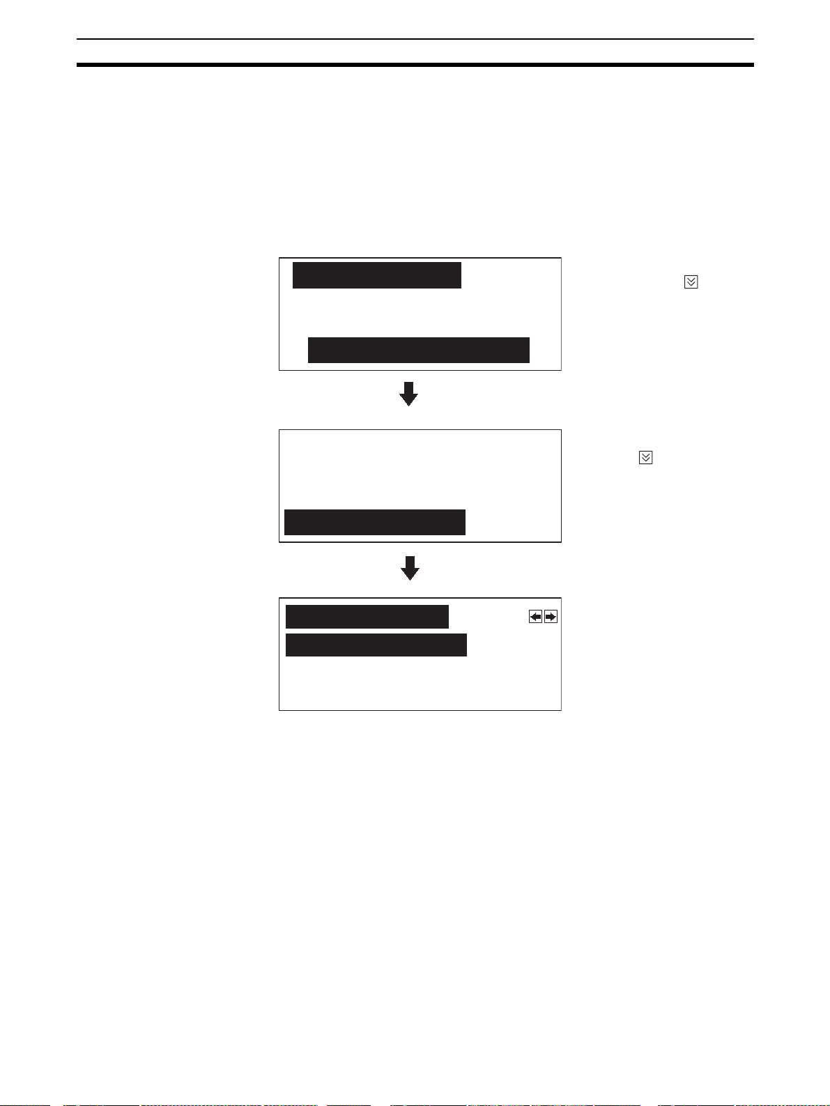
Backlight OFF Section 3-9
For details on the method for switching the backlight off with an instruction
from the PLC, refer to 5-5 NT11 Status Control (page 129).
The settings relating to the backlight OFF function that can be made with the
memory switches are: whether or not the backlight OFF function is used, and
- if it is used - what length of time will elapse before the backlight goes OFF.
The setting on shipment specifies that the backlight will go OFF after a period
of ten minutes during which there are no operations.
Select the backlight OFF time by performing the following operations, starting
from the system menu.
Select “Maintenance
[System Menu] 1.0
Quit
Mode” with the key,
then press “ENTER”.
Transmit Mode
Maintenance Mode
PT Setting
I/O Check
Select “Memory Switch”
with the key, then press
“ENTER”.
Initialize Memory
Memory Switch
Pressing the [+/–] key
[Memory SW1] Page:
Backlight OFF: 10min
Auto-restart: Yes
History Data: Erase
• To quit after setting the selection made, press the “ENTER” key.
• To quit without setting the selection made, press any two function keys
simultaneously.
• If “None” is selected, the backlight OFF function does not operate. As long
as no operations are performed, the same screen will be displayed indefinitely.
• If “10 min” is selected, the backlight will be switched OFF if no operations
are performed for ten minutes.
• If “60 min” is selected, the backlight will be switched OFF if no operations
are performed for one hour.
while “Backlight OFF” is
highlighted will cause the
selection for this item to
change cyclically in the
sequence “10 min”
“60 min” “None”.
Reference In order to maximize the service life of the backlight, select “10 min” or
“60 min” if possible.
Correct Use After images may remain if the same pattern is displayed for a long period.
To prevent the formation of an afterimage, either use the screen saver function or periodically switch screens.
79
Page 93

System Maintenance Section 3-10
3-10 System Maintenance
In order to facilitate maintenance, the NT11 is provided with functions including the I/O check function and a function for confirming the NT11 settings.
3-10-1 I/O Check
The I/O check function checks whether the inputs and outputs for the following
items are normal.
•LEDs
•LCD
•Key input
• Communication interface
LED check Carry out the LED check by performing the following operations, starting from
the system menu.
Select “Maintenance
[System Menu] 1.0
Quit
Mode” with the key,
then press “ENTER”.
Transmit Mode
Maintenance Mode
PT Setting
I/O Check
Initialize Memory
Memory Switch
[I/O Check]
Quit
I/F Check
Device Check
[Device Check]
LED Check
LCD Check
Select “I/O Check” with
the key, then press
“ENTER”.
Select “Device Check”
with the key, then press
“ENTER”.
Select “LED Check” with
the key, then press
“ENTER”.
80
Key Input Check
The “RUN” LED on the panel of the NT11 will blink.
• To quit the LED check, press any two of the function keys simultaneously.
Page 94

System Maintenance Section 3-10
LCD check Check the LCD of the NT11 by performing the following operations, starting
from the system menu.
Select “Maintenance
[System Menu] 1.0
Quit
Mode” with the key,
then press “ENTER”.
Transmit Mode
Maintenance Mode
Select “I/O Check” with
PT Setting
I/O Check
the key, then press
“ENTER”.
Initialize Memory
Memory Switch
Select “Device Check”
[I/O Check]
Quit
with the key, then press
“ENTER”.
I/F Check
Device Check
Select “LCD Check” with
[Device Check]
LED Check
the key, then press
“ENTER”.
LCD Check
Key Input Check
• In the LCD check, all of the dots that comprise the screen are displayed,
one at a time, starting at the top left corner of the screen.
The LCD check is completed when all the dots are displayed.
• To abort the LCD check, press any two function keys simultaneously.
81
Page 95

System Maintenance Section 3-10
Key input check Check the numeric keys, arrow keys, and function keys of the NT11 by per-
forming the following operations, starting from the system menu.
Select “Maintenance
[System Menu] 1.0
Quit
Mode” with the key,
then press “ENTER”.
Transmit Mode
Maintenance Mode
Select “I/O Check” with
PT Setting
I/O Check
the key, then press
“ENTER”.
Initialize Memory
Memory Switch
Display the next page by
[I/O Check]
pressing the key.
Quit
I/F Check
Device Check
Press “ENTER”.
[Device Check]
LED Check
LCD Check
Key Input Check
All the keys to be checked are displayed on the screen.
F1 F2 F3 F4
Display when
012345678
. +/- clr
• Press each of the numeric keys, arrow keys, and function keys on the
panel of the NT11 in turn.
If the corresponding key in the display is highlighted when the panel key is
pressed, it indicates that the key is operating normally.
• To quit the key input check, press any two of the function keys simultaneously.
ENTER
9
the numeric key
[9] is pressed.
82
Page 96

System Maintenance Section 3-10
Check on communication with the support tool
Check the communication between the NT11 and support tool by performing
the following operations, starting from the system menu.
Select “Maintenance
[SYSTEM MENU]
Quit
Mode” with the key,
then press “ENTER”.
Transmit Mode
Maintenance Mode
PT Setting
I/O Check
Initialize Memory
Memory Switch
[I/O Check]
Quit
I/F Check
Device Check
[I/F Check]
Quit
Tool I/F Input Check
Select “I/O Check” with
the key, then press
“ENTER”.
Select “I/F Check” with the
key, then press
“ENTER”.
Select “Tool I/F Input
Check” with the key,
then press “ENTER”.
Print Out Check
TOOL I/F INPUT CHECK
• The data received from the connected support tool is displayed in hexadecimal notation.
• To quit the check on communication with the support tool, press any two
function keys simultaneously.
83
Page 97

System Maintenance Section 3-10
Note The NT11 uses the same connector for connection to the support tool to the
PLC. If this cable is connected to equipment other than the personal computer
running the support tool, disconnect it from this equipment and connect it to
the support tool before starting the communications check.
3-10-2 PT Setting Check
Display the settings of the NT11 on the screen by performing the following
operations, starting from the system menu.
Select “Maintenance
[System Menu] 1.0
Quit
Mode” with the key,
then press “ENTER”.
Transmit Mode
Maintenance Mode
Press “ENTER”.
PT Setting
I/O Check
Initialize Memory
Memory Switch
Control Area
DM 00000
Notify Area
DM 00010
• The current settings of the NT11 are displayed.
• To quit the PT setting display, press any two function keys simultaneously.
84
Page 98

This section describes the functions of the NT11.
4-1 Outline of Functions . . . . . . . . . . . . . . . . . . . . . . . . . . . . . . . . . . . . . . . . . . . . 86
4-1-1 NT11 Screen . . . . . . . . . . . . . . . . . . . . . . . . . . . . . . . . . . . . . . . . . . . 86
4-1-2 Characters and Figures Which can be Displayed . . . . . . . . . . . . . . . 86
4-2 Screen Display . . . . . . . . . . . . . . . . . . . . . . . . . . . . . . . . . . . . . . . . . . . . . . . . 87
4-2-1 Classification of Screens. . . . . . . . . . . . . . . . . . . . . . . . . . . . . . . . . . 87
4-2-2 Screen Attributes . . . . . . . . . . . . . . . . . . . . . . . . . . . . . . . . . . . . . . . 88
4-3 Areas for Control/Notification . . . . . . . . . . . . . . . . . . . . . . . . . . . . . . . . . . . . 89
4-3-1 Allocatable Bits and Words . . . . . . . . . . . . . . . . . . . . . . . . . . . . . . . 89
4-3-2 Data Exchange in the Host Link/NT Link . . . . . . . . . . . . . . . . . . . . 89
4-3-3 NT11 Status Control and Notification to PLC . . . . . . . . . . . . . . . . . 90
4-4 Memory Tables . . . . . . . . . . . . . . . . . . . . . . . . . . . . . . . . . . . . . . . . . . . . . . . . 94
4-4-1 Character-String Memory Table. . . . . . . . . . . . . . . . . . . . . . . . . . . . 94
4-4-2 Numeral Memory Table . . . . . . . . . . . . . . . . . . . . . . . . . . . . . . . . . . 95
4-5 Bar Graphs . . . . . . . . . . . . . . . . . . . . . . . . . . . . . . . . . . . . . . . . . . . . . . . . . . . 96
4-5-1 Bar Graph Functions. . . . . . . . . . . . . . . . . . . . . . . . . . . . . . . . . . . . . 96
4-6 Numeral Setting . . . . . . . . . . . . . . . . . . . . . . . . . . . . . . . . . . . . . . . . . . . . . . . 97
4-6-1 The Numeral Setting Function . . . . . . . . . . . . . . . . . . . . . . . . . . . . . 97
4-6-2 Using Numeric Keys. . . . . . . . . . . . . . . . . . . . . . . . . . . . . . . . . . . . . 98
4-7 Menu Screen Function . . . . . . . . . . . . . . . . . . . . . . . . . . . . . . . . . . . . . . . . . . 99
4-8 Password Screen Display Function. . . . . . . . . . . . . . . . . . . . . . . . . . . . . . . . . 100
4-9 Display History Screen Function . . . . . . . . . . . . . . . . . . . . . . . . . . . . . . . . . . 101
4-10 Daily Report/Display History Printing Function . . . . . . . . . . . . . . . . . . . . . . 102
4-10-1 Printing Daily Reports . . . . . . . . . . . . . . . . . . . . . . . . . . . . . . . . . . . 102
4-10-2 Printing Display Histories. . . . . . . . . . . . . . . . . . . . . . . . . . . . . . . . . 104
SECTION 4
NT11 Functions
85
Page 99

Outline of Functions Section 4-1
4-1 Outline of Functions
4-1-1 NT11 Screen
This section gives the outline of the screen which is the basis of all NT11 functions.
For specific operation procedure using host link/NT link such as screen
switching, refer to 4-2 Screen Display (page 87).
Composition of the
Screen
Screen Management The screens displayed on the NT11 are managed by the screen numbers.
Special Screen Number Screen number “0” is reserved for the system as the no-display screen. Select
The NT11 screen is composed of horizontal 160 dots x vertical 64 dots. Each
dot is set by the combination of the X (horizontal) and Y (vertical) coordinates.
The origin of coordinates (0, 0) is set at the top left corner of the screen.
0
X coordinate (horizontal)
0
Y coordinate
(vertical)
63
Screen numbers are set when the screen data are created by using the support tool. Up to 250 screens can be set by allocating arbitrarily selected numbers 1 to 250.
The display screens can be switched or the start-up screen can be set by designating the screen number from the PLC.
this to display nothing on the NT11 screen.
Coordinates
(x, y)
159
159, 63
4-1-2 Characters and Figures Which can be Displayed
The NT11 screen can display characters, bar graphs, and other various elements.
This section describes the types and attributes of the characters and figures
which can be displayed and do not need to be changed at all.
For the settings, display, and use of the characters, numeric values, and
graphs which change according to the system operation status and other conditions, refer to 4-3 Areas for Control/Notification (page 89) and 5-3 Memory
Table Entries and Bar Graph (page 115).
The power of expression of the screen can be increased by giving various
attributes such as the enlarged or reverse display to the characters and figures.
The character and figure attributes can be set in the edit screen when creating
the screen data by using the support tool.
86
Page 100

Screen Display Section 4-2
Types and Attributes of Characters and Figures
The following types of characters can be input by using the support tool and
be displayed during operation.
Character
Type
Normal height
characters
Marks 8 x 16 Create by using the
•Marks
A mark is a graphic pattern created by 8 (horizontal) x16 (vertical) by using
the support tool. Marks can be handled the same as the normal size characters. Up to 64 patterns can be defined within the total screen data.
• Enlarged display of the characters and marks
The characters and marks can be enlarged to the following scales.
Dots
(vertical x
horizontal)
8 x 16 Alphanumerics and
Character Set Maximum Number of
symbols
support tool
Characters Displayed in One
Screen (without overwriting)
20 characters x 4 lines
(80 characters)
• Reverse and flashing display
Reverse display: The display brightness of the character and
Flashing display: Characters are displayed as they flash. The
Reverse and flashing display: The reverse display alternates with the nor-
4-2 Screen Display
This section describes the screen information required for the operation with
the NT11.
4-2-1 Classification of Screens
The NT11 is provided with the following types of screens which are classified
by the display method.
• Normal screen
• System screen
The screen type is determined by the screen number.
PT
x1 scale Double
PT
width scale
the background is reversed comparing with
the normal display.
normal display alternates with no-display.
mal display.
Normal screens (screen numbers 1 to 250)
These screens can be used without restriction by the user to create various
kinds of monitor and setting screens, including fixed displays, character displays, numeral displays, and bar graph displays.
System screen (screen number 0)
The system screen is reserved by the NT11 for system applications.
Screen No. 0 ..... Blank screen
87
 Loading...