

Omron MX2AB007, MX2AB001, MX2AB015, MX2AB022, MX2A2001 Product Information
...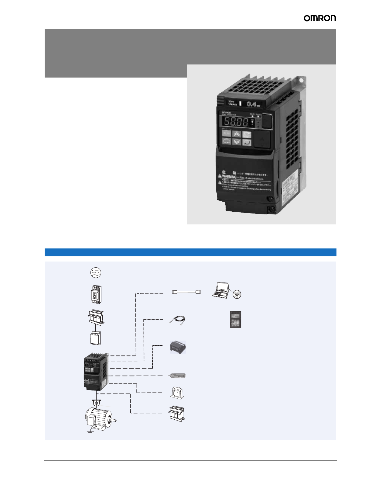
MX2
Choke
LCD 5 lines remote
operator
Remote operator
extension cable
Output AC reactor
Communication option board
USB cable
Braking resistor
CX-Drive
CX-One
MCCB
MX2
Filter
Input AC reactor
Motor
Ground
Power
supply
DC reactor
Born to drive machines
• Current vector control
• High starting torque: 200% at 0.5 Hz
• Double rating VT 120%/1 min and CT 150%/1 min
• Speed range up to 1000 Hz
• IM & PM motor control
• Torque control in open loop vector
• Positioning functionality
• Built-in application functionality (i.e. Brake control)
• User programmable as standard
• Safety embedded compliant with ISO13849-1 (double input
circuit and external device monitor EDM)
• USB port for PC programming
• 24 VDC backup supply for control board
• Fieldbus communications: Modbus, DeviceNet, Profibus,
Componet, Ethercat, ML-II and CanOpen
• PC configuration tool: CX-Drive
• RoHS, CE, cULus
Ratings
• 200 V Class single-phase 0.1 to 2.2 kW
• 200 V Class three-phase 0.1 to 15.0 kW
• 400 V Class three-phase 0.4 to 15.0 kW
System configuration
1MX2
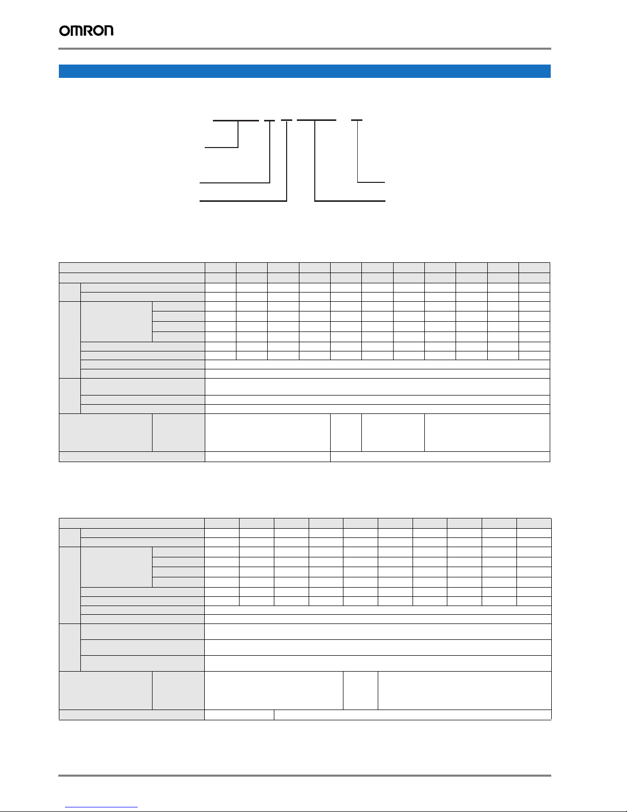
Specifications
MX2 series
A: Standard specs
MX2AB002-E
Vol tage:
B: Single-phase 200 VAC
2: Three-phase 200 VAC
4: Three-phase 400 VAC
Max. applicable motor output
002: 0,2 kW
~
150: 15,0 kW
E: Europe standard
Type designation
200 V class
Single-phase: MX2@ AB001 AB002 AB004 AB007
Three-phase: MX2@ A2001 A2002 A2004 A2007 A2015 A2022 A2037 A2055 A2075 A2110 A2150
Motor
2
kW
Inverter capacity kVA
Rated output current (A) at VT 1.2 1.9 3.5 6.0 9.6 12.0 19.6 30.0 40.0 56.0 69.0
Output
Rated output current (A) at CT 1.0 1.6 3.0 5.0 8.0 11.0 17.5 25.0 33.0 47.0 60.0
characteristics
Max. output voltage Proportional to input voltage: 0..240 V
Max. output frequency 1000 Hz
Rated input voltage
and frequency
Allowable voltage fluctuation -15%..+10%
Power
supply
Allowable frequency fluctuation 5%
Braking torque
1. Three phase model use forced-air-cooling but single phase model is self cooling.
2. Based on a standard 3-Phase standard motor.
3. Above 400 Hz with some function limitation.
For VT setting 0.2 0.4 0.55 1.1 2.2 3.0 5.5 7.5 11 15 18.5
For CT setting 0.1 0.2 0.4 0.75 1.5 2.2 3.7 5.5 7.5 11 15
200 VT
200 CT
240 VT
240 CT
At short-time
deceleration
At capacitor
feedback
Cooling method
0.4 0.6 1.2 2.0 3.3 4.1 6.7 10.3 13.8 19.3 23.9
0.2 0.5 1.0 1.7 2.7 3.8 6.0 8.6 11.4 16.2 20.7
0.4 0.7 1.4 2.4 3.9 4.9 8.1 12.4 16.6 23.2 28.6
0.3 0.6 1.2 2.0 3.3 4.5 7.2 10.3 13.7 19.5 24.9
100%: <50Hz
50%: <60Hz
Self cooling
1
AB015 AB022 - - - - -
3
Single-phase 200..240 V 50/60 Hz
3-phase 200..240 V 50/60 Hz
70%:
<50Hz
50%:
Approx 20% -
<60Hz
Forced-air-cooling
400 V class
Three-phase: MX2@ A4004 A4007 A4015 A4022 A4030 A4040 A4055 A4075 A4110 A4150
Motor
1
kW
Inverter capacity kVA
Rated output current (A) at VT 2.1 4.1 5.4 6.9 8.8 11.1 17.5 23.0 31.0 38.0
Output
Rated output current (A) at CT 1.8 3.4 4.8 5.5 7.2 9.2 14.8 18.0 24.0 31.0
characteristics
Max. output voltage Proportional to input voltage: 0..480 V
Max. output frequency 1000 Hz
Rated input voltage
and frequency
Allowable voltage
fluctuation
Power
supply
Allowable frequency
fluctuation
Braking torque
1. Based on a standard 3-Phase standard motor.
2. Above 400 Hz with some function limitation.
2 Frequency inverters
For VT setting 0.75 1.5 2.2 3.0 4.0 5.5 7.5 11 15 18.5
For CT setting 0.4 0.75 1.5 2.2 3.0 4.0 5.5 7.5 11 15
Cooling method
At short-time
deceleration
At capacitor
feedback
380 VT
380 CT
480 VT
480 CT
*3
1.3 2.6 3.5 4.5 5.7 7.3 11.5 15.1 20.4 25.0
1.1 2.2 3.1 3.6 4.7 6.0 9.7 11.8 15.7 20.4
1.7 3.4 4.4 5.7 7.3 9.2 14.5 19.1 25.7 31.5
1.4 2.8 3.9 4.5 5.9 7.6 12.3 14.9 19.9 25.7
2
3-phase 380..480 V 50/60 Hz
-15%..+10%
5%
70%:
100%: <50Hz
50%: <60Hz
<50Hz
50%:
-
<60Hz
Self cooling Forced-air-cooling
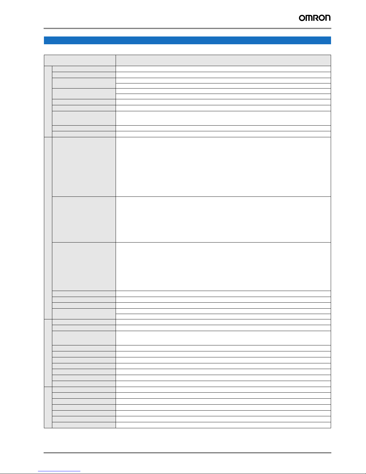
Specifications
Commom specifications
Model number
Control methods
Output frequency range
Frequency precision
Resolution of frequency set value
Resolution of output frequency
Starting torque
Control functions
Overload capability
Frequency set value
V/f Characteristics
Inputs signals
Output signals
Functionality
Standard functions
Analogue inputs
Pulse train input terminal
Accel/Decel times
Display
Motor overload protection
Instantaneous overcurrent
Overload
Overvoltage
Undervoltage
Momentary power loss
Cooling fin overheat
Protection functions
Stall prevention level
Ground fault
Power charge indication
Degree of protection
Ambient humidity
Storage temperature
Ambient temperature
Installation
Installation height
Ambient conditions
Vibration
MX2@
Specifications
Phase-to-phase sinusoidal pulse with modulation PWM (Sensorless vector control, V/F)
0.10..1000.00 Hz (with restrictions above 400Hz)
Digital set value: ±0.01% of the max. frequency
Analogue set value: ±0.2% of the max. frequency (25 ±10ºC)
Digital set value: 0.01 Hz
Analogue set value: 1/1000 of maximum frequency
0.01Hz
200% / 0.5 Hz
Dual rating:
Heavy duty (CT): 150% for 1 minute
Normal Duty (VT): 120% for 1 minute
0 to 10 VDC (10 KΩ), 4 to 20 mA (100 Ω), RS485 Modbus, Network options
Constant/ reduced torque, free V/f
FW (forward run command), RV (reverse run command), CF1~CF4 (multi-stage speed setting), JG (jog command), DB (external braking), SET (set second motor), 2CH (2-stage accel./decel. command), FRS (free run stop command), EXT (external
trip), USP (startup function), CS (commercial power switchover), SFT (soft lock), AT (analog input selection), RS (reset), PTC
(thermistor thermal protection), STA (start), STP (stop), F/R (forward/reverse), PID (PID disable), PIDC (PID reset), UP (remote control up function), DWN (remote control down function), UDC (remote control data clear), OPE (operator control),
SF1~SF7 (multi-stage speed setting; bit operation), OLR (overload restriction), TL (torque limit enable), TRQ1 (torque limit
changeover1), TRQ2 (torque limit changeover2), BOK (Braking confirmation), LAC (LAD cancellation), PCLR (position deviation clear), ADD (add frequency enable), F-TM (force terminal mode), ATR (permission of torque command input), KHC (Cumulative power clear), MI1~MI7 (general purpose inputs for EzSQ), AHD (analog command hold), CP1~CP3 (multistageposition switches), ORL (limit signal of zero-return), ORC (trigger signal of zero-return), SPD (speed/position changeover),
GS1~GS2 (STO inputs, safety related signals), 485 (Starting communication signal), PRG (executing EzSQ program), HLD
(retain output frequency), ROK (permission of run command), EB (rotation direction detection of B-phase), DISP (display limitation), OP (option control signal), NO (no function)
RUN (run signal), FA1~FA5 (frequency arrival signal), OL,OL2 (overload advance notice signal), OD (PID deviation error signal), AL (alarm signal), OTQ (over/under torque threshold), UV (under-voltage), TRQ (torque limit signal), RNT (run time expired), ONT (power ON time expired), THM (thermal warning), BRK (brake release), BER (brake error), ZS (0Hz detection),
DSE (speed deviation excessive), POK (positioning completion), ODc (analog voltage input disconnection), OIDc (analog
current input disconnection), FBV (PID second stage output), NDc (network disconnect detection), LOG1~LOG3 (Logic output signals), WAC (capacitor life warning), WAF (cooling fan warning), FR (starting contact), OHF (heat sink overheat warning), LOC (Low load), MO1~MO3 (general outputs for EzSQ), IRDY (inverter ready), FWR (forward operation), RVR (reverse
operation), MJA (major failure), WCO (window comparator O), WCOI (window comparator OI), FREF (frequency command
source), REF (run command source), SETM (second motor in operation), EDM (STO (safe torque off) performance monitor),
OP (option control signal), NO (no function)
Free-V/f, manual/automatic torque boost, output voltage gain adjustment, AVR function, reduced voltage start, motor data
selection, auto-tuning, motor stabilization control, reverse running protection, simple position control, simple torque control,
torque limiting, automatic carrier frequency reduction, energy saving operation, PID function, non-stop operation at
instantaneous power failure, brake control, DC injection braking, dynamic braking (BRD), frequency upper and lower
limiters, jump frequencies, curve accel and decel (S, U, inversed U,EL-S), 16-stage speed profile, fine adjustment of start
frequency, accel and decel stop, process jogging, frequency calculation, frequency addition, 2-stage accel/decel, stop mode
selection, start/end freq., analog input filter, window comparators, input terminal response time, output signal delay/hold
function, rotation direction restriction, stop key selection, software lock, safe stop function, scaling function, display
restriction, password function, user parameter, initialization, initial display selection, cooling fan control, warning, trip retry,
frequency pull-in restart, frequency matching, overload restriction, over current restriction, DC bus voltage AVR
2 analogue inputs 0 to 10 V (10 KΩ), 4 to 20 mA (100 Ω)
0 to 10 V (up to 24 V), up to 32 kHz
0.01 to 3600.0 s (line/curve selection), 2nd accel/decel setting available
Status indicator LED’s Run, Program, Alarm, Power, Hz, Amps
Digital operator: Available to monitor 32 items: frequency reference, output current, output frequency...
Electronic Thermal overload relay and PTC thermistor input
200% of rated current
Dual rating:
Heavy duty (CT): 150% for 1 minute
Normal Duty (VT): 120% for 1 minute
800 V for 400 V type and 400 V for 200 V type
345 V for 400 V type and 172.5 V for 200 V type
Following items are selectable: Alarm, decelerates to stop, decelerates to stop with DC bus controlled, restart
Temperature monitor and error detection
Stall prevention during acceleration/deceleration and constant speed
Detection at power-on
On when power is supplied to the control part
IP20, Varnish coating on PCB
90% RH or less (without condensation)
-20ºC..+65ºC (short-term temperature during transportation)
−10°C to 40°C
Indoor (no corrosive gas, dust, etc.)
Max. 1000 m
5.9 m/s2 (0.6G), 10 to 55 Hz
MX2 3
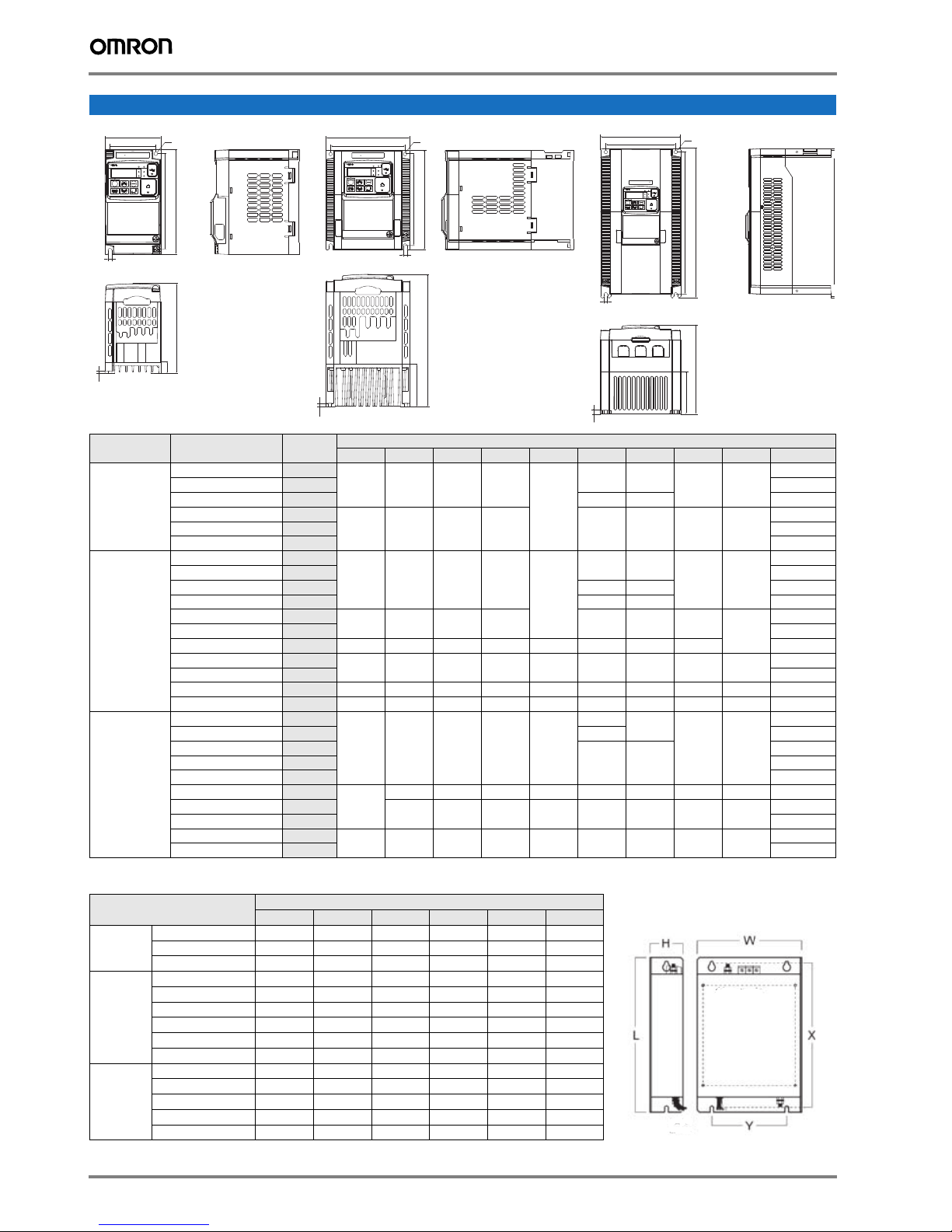
Dimensions
‚o‚v‚q
‚`‚k‚l
‚q‚t‚m
‚g‚š
‚o‚q‚f
‚q‚t‚m
‚r‚s‚n‚o
‚q‚d‚r‚d‚s
‚R‚f‚R‚l‚w‚Q?@?@
‚h‚m‚u‚d‚q‚s‚d‚q
‚o‚v‚q
‚`‚k‚l
‚q‚t‚m
‚g‚š
‚o‚q‚f
‚q‚t‚m
‚r‚s‚n‚o
‚q‚d‚r‚d‚s
‚R‚f‚R‚l‚w‚Q?@?@
‚h‚m‚u‚d‚q‚s‚d‚q
‚r‚x‚r‚c‚q‚h‚u‚d
‚o‚v‚q
‚`‚k‚l
‚q‚t‚m
‚g‚š
‚o‚q‚f
‚q‚t‚m
‚r‚s‚n‚o
‚q‚d‚r‚d‚s
‚R‚f‚R‚l‚w‚Q?@?@
‚h‚m‚u‚d‚q‚s‚d‚q
W
φ 4.5
W1
‚o‚v‚q
‚q‚t‚m
‚R‚f‚R‚l‚w‚Q
‚h‚m‚u‚d‚q‚s‚d‚q
‚`‚k‚l
‚g‚š
‚`‚`‚o‚q‚f
‚r‚s‚n‚o
‚q‚t‚m
‚q‚d‚r‚d‚s
W
W1
‚r‚x‚r‚c‚q‚h‚u‚d
‚R‚f‚R‚l‚w‚Q
‚h‚m‚u‚d‚q‚s‚d‚q
‚r‚s‚n‚o
‚q‚t‚m
‚q‚d‚r‚d‚s
HH1
φ 2-d
‚o‚v‚q
‚q‚t‚m
‚`‚k‚l
‚g‚š
‚`‚`‚o‚q‚f
H1
H
W
W1
‚R‚f‚R‚l‚w‚Q
‚h‚m‚u‚d‚q‚s‚d‚q
‚q‚t‚m
φ 2-d
‚o‚v‚q
‚q‚t‚m
‚`‚k‚l
‚g‚š
‚`‚`‚o‚q‚f
‚r‚s‚n‚o
‚q‚d‚r‚d‚s
H
H1
5
D
Figure 1
D1
2,6
Voltage class Inverter model MX2@ Figure
Single-phase
200 V
AB001
AB002
AB004
AB007
1
1 1.0
1
2
AB015 2 1.8
2 1.8
1
1 1.0
1 113 27 1.1
1 146 50 1.2
2
2 1.8
3 140 128 128 118 5 170.5 55 4.4 2.0
3
3 3.4
3 180 160 296 284 7 175 97 5 7 5.1
3 220 192 350 336 7 175 84 5 7 7.4
2
2 171 1.6
2
2 1.9
2 1.9
3
3
3 3.5
3
3 5.2
Three-phase
200 V
Three-phase
400 V
AB022
A2001
A2002
A2004
A2007
A2015
A2022
A2037
A2055
A2075
A2110
A2150
A4004
A4007
A4015
A4022
A4030
A4040
A4055
A4075
A4110
A4150
t
t
D
D1
D2
Figure 2
D
D1
D2
Dimensions in mm
W W1 H H1 t D D1 D2 d Weight (KG)
68 56 128 118
109 13.5
123 27 1.1
-
--
108 96 128 118 170.5 55 4.4 4.5
109 13.5
68 56 128 118
--
-
108 96 128 118 170.5 55 4.4
4.5
140 122 260 248 6 155 73.3 6 6
144
108 96 128 118 -
28
--
171 55
128 128 118 5 171 55 4.4 4.5 2.1
140
122 260 248 6 155 73.3 6 6
180 160 296 284 7 175 97 5 7
Figure 3
1.0
1.4
1.0
1.6
3.0
1.5
1.8
3.5
4.7
Rasmi footprint filters
Rasmi model
AX-FIM1010-RE 71 45 169 156 51 M4
1x200 V
3x200 V
AX-FIM1014-RE 111 50 169 156 91 M4
AX-FIM1024-RE 111 50 169 156 91 M4
AX-FIM2010-RE 82 50 194 181 62 M4
AX-FIM2020-RE 111 50 169 156 91 M4
AX-FIM2030-RE 144 50 174 161 120 M4
AX-FIM2060-RE 150 52 320 290 122 M5
AX-FIM2080-RE 188 62 362 330 160 M5
AX-FIM2100-RE 220 62 415 380 192 M6
AX-FIM3005-RE 111 45 169 156 91 M4
AX-FIM3010-RE 114 45 169 156 91 M4
3x400 V
AX-FIM3014-RE 144 50 174 161 120 M4
AX-FIM3030-RE 150 52 306 290 122 M5
AX-FIM3050-RE 182 62 357 330 160 M5
W H L X Y M
4 Frequency inverters
Dimensions
 Loading...