

Omron K8AB-TH11S, K8AB-TH12S Product Manual
Temperature Monitoring Relay K8AB-TH 1
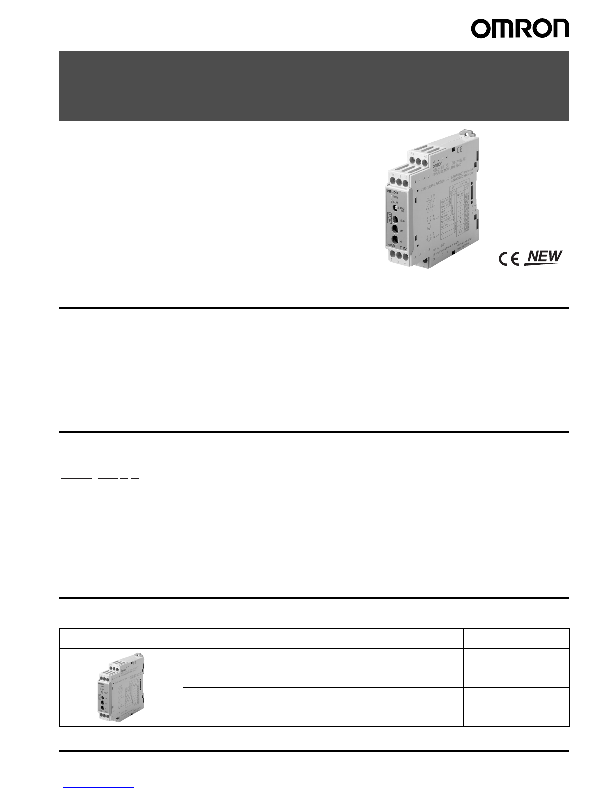
Temperature Monitoring Relay
K8AB-TH
Compact and Slim Relay Ideal for
Temperature Alarms and Monitoring
• Excessive temperature increases can be prevented and abnormal
temperatures can be monitored.
• Temperature monitoring in slim design with a width of just 22.5 mm.
• Simple function settings using DIP switch.
• Multi-input support for thermocouple or Pt100 sensor input.
• Selectable output relay: Non-fail safe/fail safe.
• Alarm status identification with LED indicator.
• CE Marking
UL/CSA certification pending.
Features
• This Temperature Monitoring Relay was designed specially for
monitoring abnormal temperatures to prevent excessive
temperature increase and to protect equipment.
• A relay capacity of 3 A at 250 VAC (resistive load) is provided.
An output latch function is also supported.
• Settings can be made and functions can be selected using the DIP
switch.
• Reduce the number of models by using multi-input support for
thermocouple or Pt100 sensor input.
Selecting Functions and Modes
• The following settings are provided: alarm mode (upper limit/lower
limit), enable/disable latch,
°C/°F, relay output non-fail safe/fail safe,
setting protection.
Terminal Wiring with Ferrules
• Wire with 2
× 2.5 mm
2
solid wire or 2 × 1.5 mm2 wiring ferrules.
Model Number Structure
■ Model Number Legend
1. Basic Model
K8AB: Measuring and Monitoring Relay
2. Function
TH1: Temperature Monitoring Relay
3. Setting Range
1: Low-temperature range (0 to 399
°C: setting in increments of
1
°C)
2: High-temperature range (0 to 1800
°C max.: setting in
increments of 10
°C)
4. Output Form
S: One SPDT relay output
Ordering Information
■ List of Models
Note: Refer to page 3 for setting ranges.
1243
K8AB-TH1@@
Temperature Monitoring Relay Input type Temperature
setting range
Setting unit Supply voltage Model
Thermocouple/
Pt100
0 to 399
°C/°F1°C/°F 100 to 240 VAC K8AB-TH11S 100-240VAC
24 VAC/VDC K8AB-TH11S 24VAC/VDC
Thermocouple 0 to 1,700
°C
0 to 3,200
°F
10
°C/°F (See note.) 100 to 240 VAC K8AB-TH12S 100-240VAC
24 VAC/VDC K8AB-TH12S 24VAC/VDC
2 Temperature Monitoring Relay K8AB-TH
Specifications
■ Ratings
■ Characteristics
Item Power supply voltage 100 to 240 VAC 50/60 Hz 24 VAC 50/60 Hz or 24 VDC
Allowable voltage range 85% to 110% of power supply voltage
Power consumption 5 VA max. 2 W max. (24 VDC), 4 VA max. (24 VAC)
Sensor inputs K8AB-TH11S Thermocouple: K, J, T, E; Platinum-resistance thermometer: Pt100
K8AB-TH12S Thermocouple: K, J, T, E, B, R, S, PLII
Output relay One SPDT relay (3 A at 250 VAC, resistive load)
External inputs
(for latch setting)
Contact input ON: 1 k
Ω max., OFF: 100 kΩ min.
Non-contact input ON residual voltage: 1.5 V max., OFF leakage current: 0.1 mA max.
Leakage current: Approx. 10 mA
Setting method Rotary switch setting (set of three switches)
Indicators Power (PWR): Green LED, Relay output (ALM): Red LED
Other functions Alarm Mode (upper limit/lower limit), non-fail safe/fail safe selection, output latch, setting protection, temperature
unit
°C/°F
Ambient operating temperature
−10 to 55°C (with no condensation or icing)
Ambient operating humidity Relative humidity: 25% to 85%
Storage temperature
−25 to 65°C (with no condensation or icing)
Setting accuracy ±2.0% of full scale
hysteresis width 2
°C
Output relay Resistive load 3 A at 250 VAC (cos
φ = 1), 3 A at 30 VDC (L/R = 0 ms)
Inductive load 1 A at 250 VAC (cos
φ = 0.4), 1 A at 30 VDC (L/R = 7 ms)
Minimum load 10 mA at 5 VDC
Maximum contact voltage 250 VAC
Maximum contact current 3 A AC
Maximum switching capacity 1,500 VA
Mechanical life 10,000,000 operations
Electrical life Make: 50,000 times, Break: 30,000 times
Sampling cycle 500 ms
Insulation resistance 20 M
Ω (at 500 V) between charged terminals and exposed uncharged parts
20 M
Ω (at 500 V) between any charged terminals (i.e., between input, output, and power supply terminals)
20 M
Ω (at 500 V) between contacts (open)
Dielectric strength 2,000 VAC 50/60 Hz for 1 min between charged terminals of different polarity
Vibration resistance
Vibration of 10 to 55 Hz and acceleration of 50 m/s
2
for 5 min with 10 sweeps each in X, Y, and Z directions
Shock resistance
150 m/s
2
(100 m/s2 for relay contacts) 3 times each in 6 directions in X, Y, and Z directions
Weight 130 g
Degree of protection IP20
Memory protection Non-volatile memory (number or writes: 200,000)
Safety
Standards
Approved standards EN 61010-1
Application standards EN 61326 and EN 61010-1 (pollution level 2, overvoltage category II)
EMC EMI: EN 61326
Radiation Interference Field Intensity: EN 55011 Group 1 Class A
Noise Terminal Voltage: EN 55011 Group 1 Class A
EMS: EN 61326
Immunity ESD: EN 61000-4-2: 4 kV contact discharge (level 2)
8 kV air discharge (level 3)
Immunity RF: EN 61000-4-3: 10 V/m, amplitude-modulated
(80 MHz to 1 GHz, 1.4 GHz to 2 GHz) (level 3)
Immunity Burst: EN 61000-4-4: 2 kV power line (level 3)
2 kV output line (relay output) (level 4)
1 kV measurement line and I/O signal lines (level 4)
Immunity Conducted Disturbance: EN 61000-4-6: 3 V (0.15 to 80 MHz) (level 3)
Immunity Surge: EN 61000-4-5: 1 kV line-to-line: power line, output line
(relay output) (level 2)
2 kV line-to-ground: power line, output line
(relay output) (level 3)
Commercial Frequency
Immunity Magnetic Field: EN 61000-4-8: 30 A/m (50Hz) continuous time
Immunity Voltage Dip/Interrupting: EN 61000-4-11: 0.5 cycle, 100% (rated voltage)
Terminal screw tightening torque 0.54 to 0.55 N·m
Crimp terminals
Two solid wires of 2.5 mm
2
or two ferrules of 1.5 mm2 with insulation sleeves can be tightened together.
Case color Munsell 5Y8/1 (ivory)
Case material ABS resin (self-extinguishing resin)
Mounting Mounted to DIN Track or with M4 screws
Dimensions 22.5
× 100 × 90 mm (W × D × H)
Temperature Monitoring Relay K8AB-TH 3
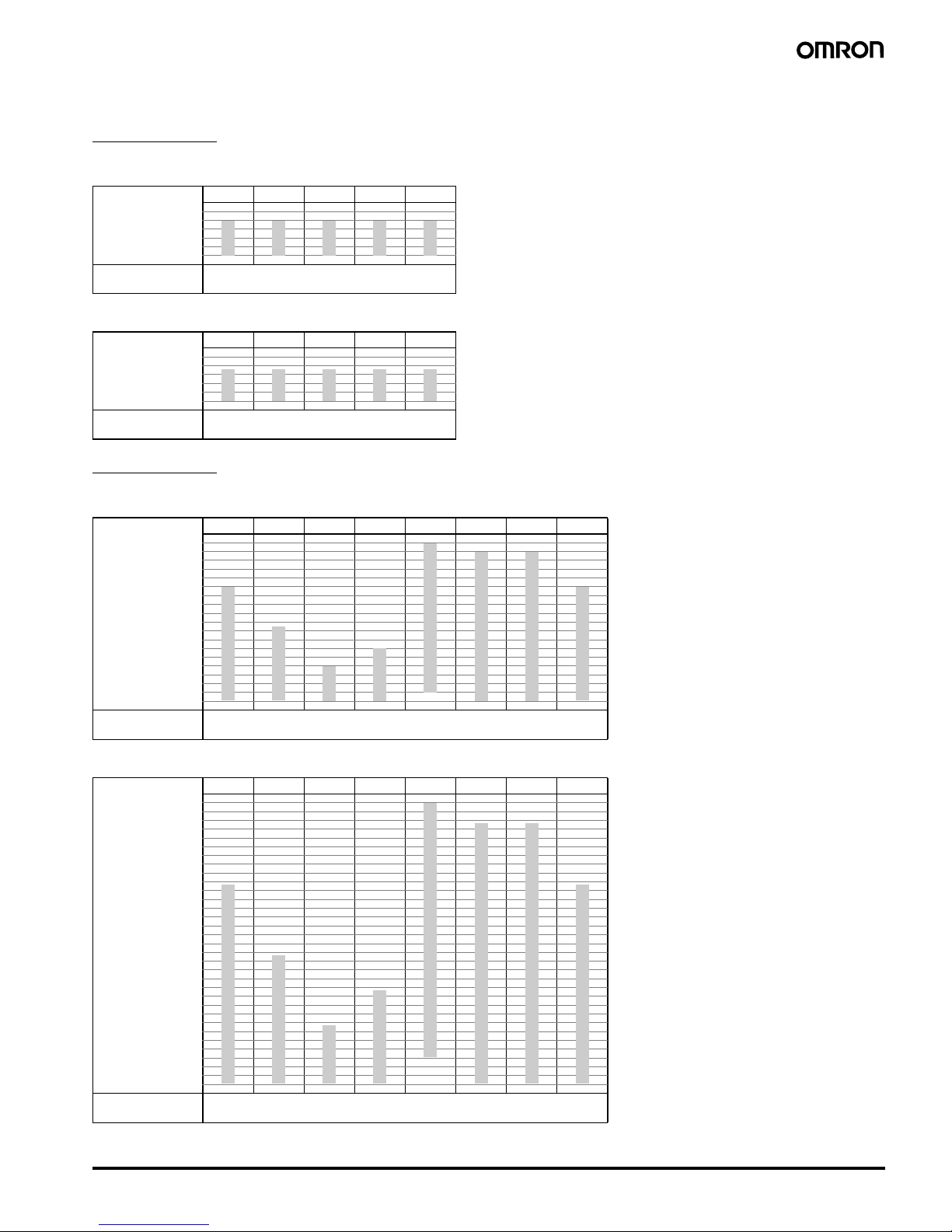
■ Setting Ranges
K8AB-TH11S
Centigrade
Fahrenheit
K8AB-TH12S
Centigrade
Fahrenheit
Input KJTEPt100
Setting
temperature range
500
400
300
200
100
0
399 399 399 399 399
00000
Minimum setting
increment
1°C
Input KJTEPt100
Setting
temperature range
500
400
300
200
100
0
399 399 399 399 399
00000
Minimum setting
increment
1°F
Input KJTEBRSPLII
Setting
temperature range
1,800
1,700
1,600
1,500
1,400
1,300
1,200
1,100
1,000
900
800
700
600
500
400
300
200
100
0
1,800
1,700 1,700
1,300 1,300
850
600
400
100
0000 000
Minimum setting
increment
10°C
Input KJTEBRSPLII
Setting
temperature range
3,200
3,100
3,000
2,900
2,800
2,700
2,600
2,500
2,400
2,300
2,200
2,100
2,000
1,900
1,800
1,700
1,600
1,500
1,400
1,300
1,200
1,100
1,000
900
800
700
600
500
400
300
200
100
0
3,200
3,000 3,000
2,300 2,300
1,500
1,100
700
300
0000 000
Minimum setting
increment
10°F
 Loading...