

Page 1
HEM-9000AI
Non-Invasive
Blood Pressure Monitor
with Augmentation Index (AI)
• Instruction Manual
• Mode d’emploi
• Gebrauchsanweisung
• Manuale de instructone
• Manual de instrucciones
• Gebruiksaanwijzing
•
XXXXXXXXXXXXXXXXXXXXXXXX
EN
IM-HEM9000-AI-E-01-07/06
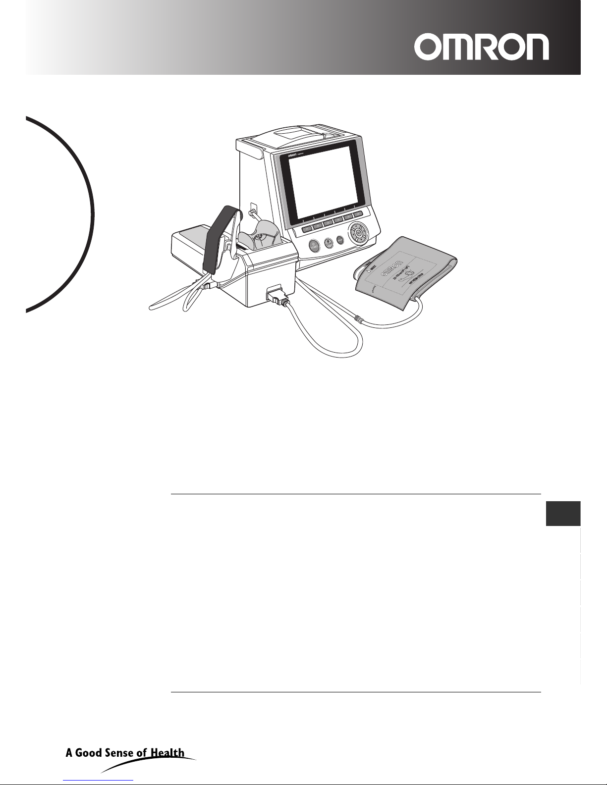
Thank you for purchasing the OMRON HEM-9000AI unit.
Read all of the instructions in the instruction manual before you operate the unit
and keep it near the unit all the times for future reference.
FR
DE
IT
ES
NL
CZ
Page 2

2
Contents
1. Indications .................................................................................... 4
2. Exemptions .................................................................................. 5
3. Notes on Safety ........................................................................... 6
4. Cleaning and Maintenance ........................................................11
5. Package Contents ...................................................................... 12
5.1. Main Unit ............................................................................. 12
5.2. Accessories (Included and Sold Separately) ...................... 12
6. Accessories ............................................................................... 13
7. Introduction to the HEM-9000AI ............................................... 14
8. General Preparation .... .............................................................. 15
8.1. Component Names/Descriptions ........................................ 15
8.2. Connecting the Main Unit and AI Pulse Wave
Measurement Unit Inserting the Memory Card ................... 17
8.3. Setting the Date and Time .................................................. 19
8.4. Setting the Blood Pressure/AI Measurement Method
and Registering ID Information ........................................... 22
8.5. Loading Printer Paper ......................................................... 23
9. Measurement Preparation ......................................................... 24
9.1. How to Apply the Blood Pressure Cuff ................................ 24
9.2. How to Apply the AI Pulse Wave Sensor Unit .................... 26
10. Post - Measurement .................................................................. 29
10.1.How to Remove the AI Pulse Wave Sensor Unit ................ 29
11. Selecting the Measurement Method ........................................ 30
11.1. Selecting the Measurement Method ................................... 30
12. AI + Blood Pressure Measurement .......................................... 31
12.1.Measuring AI + Blood Pressure Together ........................... 31
13. Blood Pressure Measurement .................................................. 36
13.1.Blood Pressure Measurement ............................................ 36
13.2. Auscultation ........................................................................ 38
14. AI Measurement ......................................................................... 40
14.1.AI Measurement .................................................................. 40
14.2.Changing Magnification and Scroll Speed .......................... 43
15. Print ............................................................................................ 44
15.1.Printing Measurement Results ............................................ 44
Page 3

3
EN
16 Memory Retrieval ....................................................................... 46
16.1.Show All Data List ............................................................... 46
16.2.ID Search ............................................................................ 48
16.3.Delete Data ......................................................................... 49
16.4.Data Detail .......................................................................... 50
16.5.Print Continuous Pulse Waves ........................................... 51
16.6.Trend Graph ........................................................................ 53
16.7.Adding and Modifying Blood Pressure
Measurement Values .......................................................... 55
17. Registering ID Information ....................................................... 57
17.1.ID Registration .................................................................... 57
17.2.Retrieval / Edit ID ................................................................ 61
17.3.Replace ID .......................................................................... 63
18. Configuration Options .............................................................. 64
18.1.How to Change the Settings .............................................. 64
18.2.How to Change the Setup ................................................... 66
18.3.How to Change the Measurement Settings ........................ 67
18.4.How to Change Settings for Printing ................................... 70
18.5.How to Change Display/Sound Settings ............................. 74
18.6.How to Change the Clock Settings ..................................... 76
18.7.How to Change Settings for Storing .................................... 77
18.8.Returning to the Default Settings ........................................ 78
18.9.Registering Hospital Name ................................................. 79
18.10.Memory Card ..................................................................... 80
18.11.Keyboard ............................................................................ 82
19. Calibration Measurement .......................................................... 83
19.1.How to Execute a Test Measurement ................................. 83
20. Introduction to Troubleshooting .............................................. 85
21. Error List .................................................................................... 86
22. Specifications ............................................................................ 92
Page 4

4
1.Indications
1. Indications
Indications for use
The HEM-9000AI is intended to measure systolic and diastolic blood pressure and pulse rate in
adults with an arm circumference of 17-42 cm, and to calculate radial augmentation index (AI).
The HEM-9000AI is intended for use in physicians’ offices, hospitals, clinics and other medical
facilities where non-invasive blood pressure and radial AI measurements/calculations are
performed on patients and invasive measurement is contraindicated.
The Augmentation Index (AI) function of the HEM-9000AI has not been evaluated on patients who
have intra-ventricular conduction delays (VCD).
Contraindications for use
As with any non-invasive measurement device, there are clinical conditions which can influence
the accuracy of the results. Also, the subject’s position, physiological condition and other
environmental factors can affect the measurement/calculation.
The OMRON HEM-9000AI Non-Invasive Blood Pressure Monitor with Augmentation Index should
not be used with patients who have the following conditions:
1. Patients with a known arrhythmia.
2. Patients with insufficient peripheral circulation, acute cases of low blood pressure or low
temperature.
3. Patients who use a pacemaker.
4. Patients experiencing a seizure.
5. Children younger than 18 years old.
6. Patients who should not have blood pressure measurements taken from their arms.
7. Patients with an artificial heart.
8. Patients whose artery cannot be found by palpation.
Page 5

5
2.Exemptions
EN
2. Exemptions
Read and familiarize yourself with all Instruction Manual materials, including the instructions for
use, warnings, precautions, limitations and capabilities before using the OMRON HEM-9000AI
Device.
OMRON will not bear any responsibilities on the following matters.
1.When a problem or damage occurs caused by the maintena nce and/or rep air cond ucted by a
person other than OMRON or the dealer specified by OMRON.
2.The problem or damage of OMRON product caused by the produ ct of othe r man ufacturer not
delivered by OMRON.
3.The problem and damage caused by the maintenance and/or repair using the rep air p art s not
specified by OMRON.
4.The problem and damage caused by the results not observing the Notes on Safety or the
operational method mentioned in this Instruction Manual.
5.Under the circumstances not within the operating conditions of this unit including the power
source or the setting environment mentioned in this Instruction Manual.
6.The problem and damage caused by the result(s) of remodeling or improper repair of this
product.
7.The problem and damage caused by act of god such as fire, earthquake, flood, or lightening.
1.The contents of this lnstruction Manual may be changed without prior notice.
2.We have thoroughly reviewed the contents of this lnstruction Manual.
However, if an inadequate description or error is found, please let us know.
3.It is prohibited to copy a part of or the entire lnstruction Manual without obtaining OMRON’s
permission. Unless this lnstruction Manual is used by an individual (company), it cannot be
used without getting OMRON’s permission from the standpoint of the Copyright Law.
Page 6
6
3.Notes on Safety
3. Notes on Safety
GIVE PARTICULAR ATTENTION TO ALL SAFETY PRECAUTIONS
Warning signs and graphic symbols are intended for the safe and correct use of the product, and
to prevent harm or damage to you and others.
Symbols and definitions are as follows:
Warning
Indicates a possibility that people will suffer death or serious injury resulting from
incorrect use.
Caution
Indicates a possibility that people will be injured or objects will be damaged resulting from
incorrect use.
Page 7

7
3.Notes on Safety
EN
Warning:
Clinical
•Do not use unless you are a healthcare worker.
•Do not use for monitoring vital signs in an intensive care unit.
•The device has a safety mechanism built in to prevent pressure from rising above 300 mmHg. If
this safety mechanism fails or pressurization fails to stop while measuring, disconnect the AI
pulse wave sensor unit or cuff, or unplug the air tube from the blood pressure monitor itself.
•Peripheral nerve damage might result.
•Do not apply a cuff or use the AI pulse wave measurement unit on an arm being transfused or
injected with an intravenous injection.
•Intravenous injection or transfusion cannot be performed properly.
•Do not use this device on patients who cannot clearly describe their pain.
•It may cause injury to the user if cuff pressurization release stops or pulse wave sensor
pressure release is delayed.
•Do not use this device during an MRI scan.
•It might cause an accident.
•If a power outage occurs while the device is measuring, promptly detach the cuff and pulse wave
sensor unit.
•Injury may result when pressing the wrist for a long period.
•Do not slide the AI pulse wave sensor during AI measurement.
•Injury to the wrist might result.
Device Set Up
•Do not touch the power cord with a wet hand.
•Electric shock might result.
•Do not use cords except those provided.
•Electric shock might result.
•Do not plug into outlet without grounding pin or pin receptacle.
•If plugged into incorrect outlet, electric shock might result.
Device Use
•Plug the main unit into an outlet (do not plug into a multi-plug outlet adapter).
•Fire or electrical shock might result.
•Plug the power cord in firmly. Clean dust off on the power cord.
•Electric shock, a short-circuit or fire might result.
•Do not use when the power cord is damaged or not firmly plugged in.
•Electric shock, a short-circuit or fire might result.
•Do not pull the power cord when unplugging the power cord from an outlet.
•It might cause fire or electric shock due to breaking or short circuiting the power cord.
•Do not use in the presence of a flammable gas or where flammable gas may be generated or
released. (e.g., combustible anesthetics, hyperbaric chambers, oxygen tents, in presence of
combustible/flammable liquids.)
•Explosion or fire might result.
•When you use this device with other medical devices, read the instruction manuals of those
devices carefully. Ensure that all the warnings and notes are also understood on those devices
before using.
•If the following cases or situations occur, stop using this device immediately, turn it off, unplug the
power cord from the outlet, and contact OMRON.
•If there is smoke or an unusual order.
•If this device is dropped or subject to a strong impact.
•If liquid or foreign substances enter the device.
•Failure state.
•Electric shock, a short circuit or fire might result.
•In addition, follow the instructions below in any of the above situations:
•Display an “Out of Order, Do Not Use” sign on the front of the main unit.
•Stop using the device.
•Electric shock might result.
Page 8

8
3.Notes on Safety
•Do not disassemble or modify this device.
•Electric shock, fire, failure or malfunction might result.
•Do not use with any cuffs except those provided by OMRON specifically for this device and
model.
•It might cause incorrect measurement results.
•Do not use any power cords except power cords provided by OMRON specifically for this device.
•Fire or electric shock might result.
•Do not replace the fuses on your own.
•Fire or electric shock might result.
•The fuses are specifically designed for this device. Contact Professional Services for
replacement of the fuses.
•Do not connect the HEM-9000AI to commercial computers or devices that do not meet medical
safety standards:
•This could cause electric shock.
•This device meets medical safety standards and the leakage current is limited to be within
standard specifications.
•Apply the pulse wave sensor on bare skin.
•Pulse waves might not be detected, and unnecessary pressure might be applied on the
pulse wave sensor.
•The user might be injured.
Device Maintenance
•After using the unit or cleaning, do not plug the power cord into a mains outlet until the unit and
power cord are sufficiently dry.
•Fire or electric shock might result.
•Do not place or store in a place that can be reached by water or chemicals.
•Electric shock might result.
Page 9

9
3.Notes on Safety
EN
Caution:
Clinical
•When results seems unreliable, use other measurement procedures prior to invasive techniques.
•Make sure that the patient does not touch this device while the test is being conducted.
•Only measure when the patient is quiet, not talking or moving.
•In the following cases, check blood pressure and pulse by auscultation:
(a) When an irregular pulse wave is found
•Advise the patient not to shake or move the body while measuring. This may cause a
condition similar to irregular pulse wave.
(b) When an error occurs or you have doubt about the measurement value.
•An incorrect measurement may be registered due to external vibration or patient
movement while measuring.
•A measurement error or inability to measure may occur in cases of abnormal
peripheral circulation or very low blood pressure.
•A measurement error or inability to measure may occur in cases of a patient with a
short blood pressure fluctuation, such as an irregular heartbeat.
Device Set up
•Do not connect the air tube, cuff or AI pulse wave measurement unit to another device.
•Erroneous results may occur.
•Do not insert or remove the AI pulse wave sensor if a connector or an air tube is unplugged.
•It may cause damage to the AI pulse wave sensor or pressure air bag might result.
•Do not place this device upside down.
•Electric parts and mechanical parts might break down.
Device Use
•Do not install parts or instruments not specified for this device.
•Do not push the buttons or LCD display with any sharp or hard material.
•Failure or damage might result.
•Do not touch the AI pulse wave sensor with any sharp or hard material.
•Damage might result.
•Do not insert and remove the memory card while saving or retrieving data.
•Memory card data damage might result.
•Make sure the time is set correctly on the main unit.
•Measurement might be recorded with the wrong time.
•Turn off the power to the unit and unplug the power cord from the electrical outlet before moving
the unit.
•Do not insert or remove the AI pulse wave sensor while measuring AI.
•It may cause damage to the AI pulse wave sensor or pressure air bag might result.
•Do not inflate without wrapping the cuff around the arm.
•Do not use a damaged cuff.
•Do not use a cellular phone or a radio transceiver in the room where this device is located.
•Malfunction might result.
•Do not use other medical devices near this device.
•Malfunction might result.
•Other medical devices might be affected.
•This device might be affected by an electric appliance or microwave apparatus. Do not use any
electronics or microwaves in the vicinity of this device.
•Do not use in extreme meteorological environments, such as unmanaged high temperature, high
humidity, low temperature, and low humidity.
•Malfunction might result.
•Do not use this unit in a vehicle, such as an ambulance.
Page 10

10
3.Notes on Safety
•Do not use any printer paper other than the printer paper provided by OMRON specifically for this
device and model.
•Damage to the printer might result.
•Printed text, waveforms and measurement results may smear or fade.
•Do not pull on paper before printing is complete.
•Damage to the printer might result.
•Use only an OMRON designated memory card.
•Using memory cards not designated for use with this device might result in measurement
results or ID information not saving correctly, or might prevent them from being retrieved
later.
•Do not drop this device.
•Do not put anything on this device.
•The printer cover might crack.
•Do not install or store this unit near water or liquid medication.
•Electric parts might break down.
•A patient might receive an electric shock.
•Do not slide the pulse wave sensor when the power supply is off.
•The pulse wave sensor might be damaged.
•Attach the Pulse Wave Sensor Unit properly. (Refer to Section 9.2.)
•The device might display an inaccurate measurement result.
•Apply the Blood Pressure Cuff properly. (Refer to Section 9.1.)
•The device might display an inaccurate measurement result.
Device Maintenance
•Unplug the main unit connector from outlet when not in use for a long period.
•Electric shock or an electric discharge fire due to deterioration of the insulating material
might result.
•Turn off and unplug the main connector when installing/removing parts or performing
maintenance.
•Electric shock or injury might result.
•Do not damage, modify, bend forcefully, pull, twist, or bundle the power cord. In addition, do not
put heavy material on it.
•Failure or damage might result.
•Do not disinfect this device by autoclave or gas sterilization.
•Damage might result.
•The user might get a rash.
•Do not wash with water or immerse in water.
•Damage might result.
•The device may display an inaccurate measurement result.
•Do not slide the AI pulse wave sensor when the power supply is off.
•It may cause damage to the AI pulse wave sensor.
•Be sure to inspect the unit on regular basis. Check accuracy on a 1 year interval.
Shipping
•This is a high-precision device. Before shipping this device contact OMRON for shipping
instructions.
Page 11
11
4.Cleaning and Maintenance
EN
4. Cleaning and Maintenance
Maintenance prior to use
1. Check this device regularly.
2. When not in use for a long time, ensure that this device functions correctly and safely before
using it.
•Check all cord, cable and tube connections.
•Check that this device functions correctly by checking button functions.
•Check that the time displayed on the device is accurate.
3. Do not install or store this unit in the following conditions:
•In direct sunlight.
•In a location that is dusty or has high air salinity.
•On a sloping or vibrating object that creates impact
•Where chemicals are stored or combustible gas is generated.
•In high temperature or high humidity.
•Where water, liquid medications or chemicals may be spilled.
Maintenance after use
Store this device and the attachments after performing the proper maintenance and in an
orderly way.
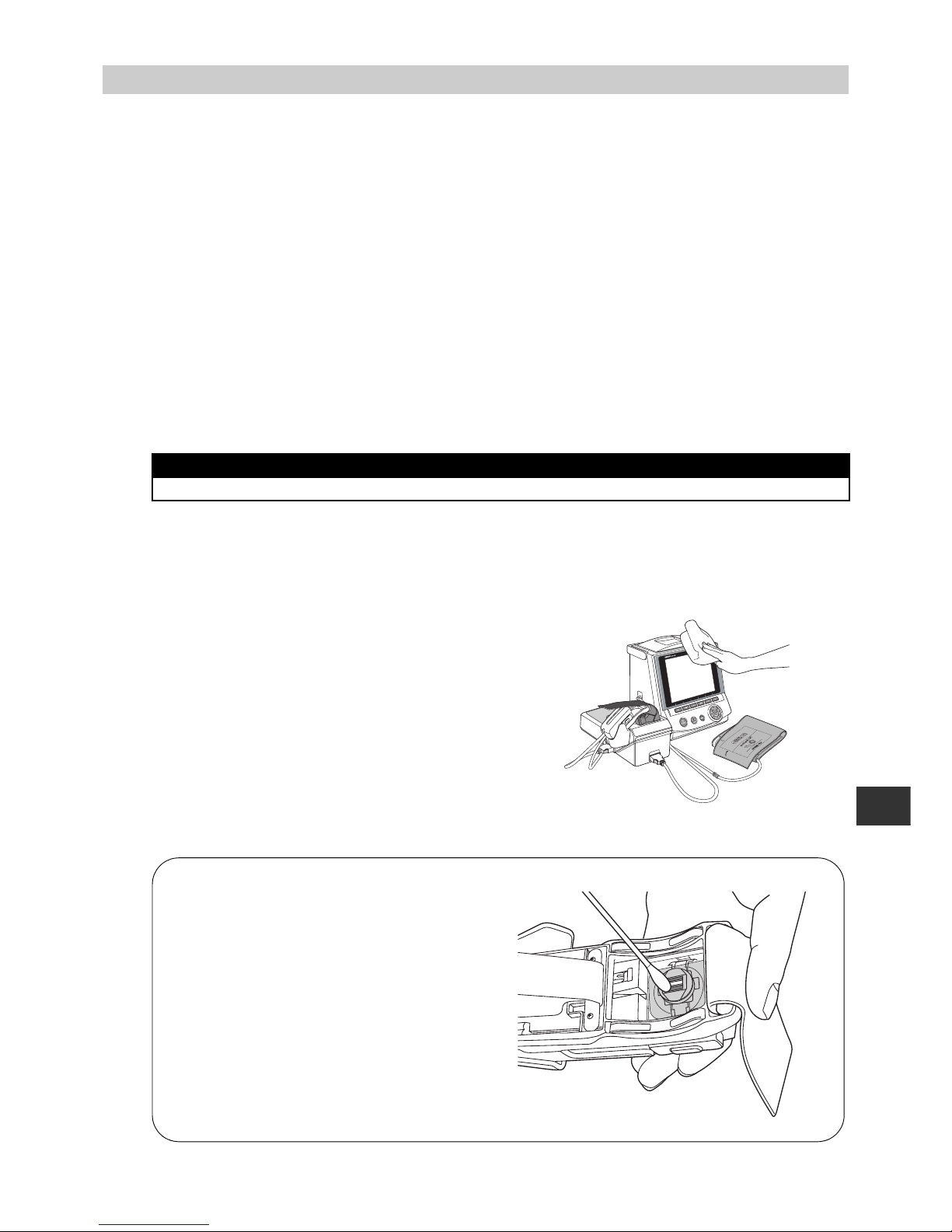
Clean the surface of the main unit, the surface of the wrist rest, the outside of the AI pulse
wave measurement unit, the cuff and cables with the following procedure.
1. Use a damp cloth with 30 to 50% isopropyl alcohol or
70% ethyl alcohol for cleaning the surface.
DO NOT use gasoline, thinner, benzene or highly
concentrated alcohol when cleaning this device.
Do not disinfect this unit by autoclave or gas
sterilization (EOG, formaldehyde, or high
concentration ozone), or do not implement ultraviolet
disinfection.
Do not wash or wet the wrist belt.
Do not wash or wet the cuff.
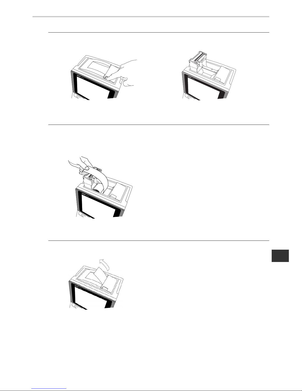
2. Wipe with a soft, dry cloth. [Fig. 1]
PLEASE NOTE
•Do not sterilize
ART.
INDEX
INDEX
MAX
MAX
[Fig. 1]
Turn the power on.
Slide the pulse wave sensor into position as
illustrated in [Fig. 2].
Turn the power off.
Wipe the sensor gently with a dry clean cotton
swab or with a moistened cotton swab dipped in
diluted rubbing alcohol. [Fig. 2]
After cleaning is completed, turn the power on.
Slide the AI pulse wave sensor back in holder.
Note: The sensor may be damaged or scratched if the
power is off when sliding pulse wave sensor.
[Fig. 2]
Be careful when cleaning the AI pulse wave sensor!
Page 12
12
5.Package Contents
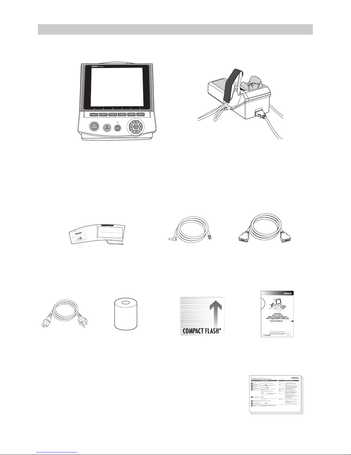
5. Package Contents
5.1. Main Unit
5.2. ACCESSORIES (Included and Sold Separately)
Items identified with an asterisk (*) are consumable and not covered under the warranty
Main Unit (display unit)
AI Pulse Wave Measurement Unit
(Including the AI pulse wave sensor unit)
RANGE
MIN
MAX
INDEX
ART.
22
~
32cm
(
9"
~
13"
)
REF
HEM
CR19
TUBE
Adult arm cuff
(in 3 sizes - S, M and L with built-in air bag)
See cuff size information in Section 6,
ACCESSORIES.
Air Tube (1.3 m)
Model: HEM-9T1.3
Art no.: 6984328-4
Connection Cable
Model: HEM-9000-CABLEZ
Art no.: 9956251-4
Power Cord
Model: NEU12-2
Art no.: 1096522-0
Printer Paper*
(1 Roll Included)
Sold 5 rolls to a box
Model: HEM-9000-PAPERZ
Art no.: 6970159-5
Memory Card to record*
measurements (128 MB)
Model: HEM-9000-IC128Z
Art no.: 9956250-6
Instruction Manual
(Including warranty card)
Art no.: 1658718-9
Quick Start Instruction
Manual
Art no.: 1664287-2,
1664288-0,
1664289-9
Page 13
13
6.Accessories
EN
6. Accessories
ACCESSORIES (Sold Separately)
To purchase accessories or replacement parts call OMRON.
•Large size
adult arm cuff
Model: HEM-9CLC
Art no.: 4928654-0
Applicable arm circumference:
32 to 42 cm
•Medium size adult arm
cuff
Model: HEM-9CMC
Art no.: 4928640-0
Applicable arm circumference:
22 to 32 cm
•Small size adult arm cuff
Model: HEM-9CSC
Art no.: 4928639-7
Applicable arm circumference:
17 to 22 cm
•Air Tube (1.0 m)
Model: HEM-TUBE-100X
Art no.: 6984327-6
•Keyboard
Model: HEM-9000-KEYBZ
Art no.: 9951049-2
•Wheeled Cart
(with basket to place cuff)
Model: HEM-9000-STANDZ
Art no.: 7980234-9
•Memory Card (128MB)
Model: HEM-9000-IC128Z
Art no.: 9956250-6
•Printer Paper (5 Roll Set)
Model: HEM-9000-PAPERZ
Art no.: 6970159-5
•Power Cord (for U.K.)
Model: HEM-9000-ACCAU
Art no.: 9983975-3
INDEX
ART.
RANGEMIN
MAX
32
~
42cm
(
13"
~
17"
)
REF
HEM
CL19
TUBE
RANGE
MIN
MAX
INDEX
ART.
22
~
32cm
(
9"
~
13"
)
REF
HEM
CR19
TUBE
ART.
RANGE
MIN
MAX
INDEX
REF
HEM
CS19
17
~
22cm
(
7"
~
9"
)
TUBE
Page 14
14
7.Introduction to the HEM-9000AI
7. Introduction to the HEM-9000AI
Functional Description
The OMRON Non-Invasive Blood Pressure Monitor with AI, HEM-9000AI, has been
developed for blood pressure measurement and AI calculations.
Blood pressure measurement is obtained via digital oscillometric method using a blood pressure cuff. An
accompanying AI calculation is made based on several components of the patient's pulse wave, which is
obtained through applanation tonometry (measures pressure required to indent the artery) using a sensor
placed against the radial artery.
Configuration of Pulse Waves
A pulse wave is a wave in a blood vessel generated when blood is pressurized into the aorta by the
contraction of the heart. The pressure changes within the blood vessels create the wave action, and this is
called a pressure pulse wave. Looking closely at the wave, it consists of two primary ele ments: ejected wave
and reflected wave.
(Refer to Figure 1)
The ejected wave is generated by the contraction of the heart, which sends blood throughout the body. The
reflected wave is generated by the reflection of the ejected wave, after the ejected wave propagates
throughout the body, reflecting from an artery bifurcation or from a peripheral artery.
The pattern formed by the superimposition of these two wave elements is regarded as the pulse wave
pattern.
In addition, an incisura (notch) on the back of the reflected wave represents a pressure change caused by
reverse flow as the aortic valve, located at the opening of the aorta, is closed.
Pulse Wave and Blood Pressure
The pulse wave represents a local blood pressure change caused by the passage of blood from the left
ventricle into the aorta, accompanied by the wave action through the artery. Systolic blood pressure is
measured during the period of ventricular contraction, creating a wave. Diastolic blood pressure is measured
between periods of ventricular contraction.
AI is defined as
AI defines an amplitude value ratio of the peak point (P2) at which the reflected wave is overlapped to the
peak point (P1) at which the ejected wave is overlapped. (Refer to Figure 2)
What AI indicates
When a peripheral blood vessel is stiff, the reflected wave becomes larger. When the blood vessels in the
pulse wave propagation path are stiff, the time in which the reflected wave returns becomes shorter. As a
result, the peak of the reflected wave will be near the peak of the ejected wave. Both of these phenomena
increase AI. The heart enhances myocardial contractility to overcome the increased blood pressure. If this
lasts for a long time, the heart will become strained, showing that when the AI is higher, the “load on the
heart” is higher.
Ejected wave
incisura
Ejected wave
Reflected wave
Reflected wave
The pulse wave is represented
by a combination of the "ejected"
and the "reflected" wave.
[Figure 1] [Figure 2]
P1 P2
Page 15
15
8.General Preparation
EN
8. General Preparation
8.1. Component Names/Descriptions
A. Printer cover
B. Print paper storage (built-in)
C.Print paper release button
D.Air connector
E. Handle
F. Memory card slot
G. Eject button
H.Main unit
I. START button
J. STOP button
K. DISPLAY button
L. DISPLAY light
M.LCD display
The material used in the front of the panel is
PMMA.
N.Function keys
O.Left, right, up, down movement/select
buttons
P. SET button
Q.Power switch
R.Power connector
S. AI measurement unit connector
T. USB connectors × 2
U.Maintenance connector (not used)
A
D
E
I
M
N
O
P
J
K
L
Q
R
S
T
U
B
C
F
G
H
Page 16
16
8.General Preparation
A. Slide stoppers
B. Palpation window
C.Base line
D.Indicator lights
E. AI Pulse Wave sensor unit
F. AI Pulse Wave sensor unit connector
G. Air connector
H.Elbow placement board
I. AI Pulse Wave sensor unit storage
clip
J. Rubber wrist rest
K. Main unit connector
L. Wrist belt
M.Fastener
A
E
F
G
H
B
C
I
J
L
M
K
D
C
Page 17
17
8.General Preparation
EN
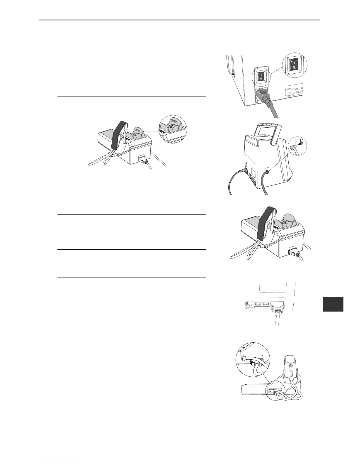
8.2. Connecting the Main Unit and AI Pulse Wave Measurement Unit
Inserting the Memory Card
1. Make sure that the power switch is in the OFF
position. [Fig. 1]
2. Insert the air plug of the blood pressure cuff in the air
connector on the left side of the main unit. (Refer to
9.1.) [Fig. 2]
3. Attach the rubber wrist rest to the pulse wave
measurement unit
Attach the wrist rest so that the side marked “thumb
side” is on the thumb side of the arm (i.e., the thumb
side is on the left side of the patient when using the
patient’s left hand for measurement and on the
patient’s right side for right-hand measurement).
4. Plug one end of the connection cable (see Section 5.
for illustration) into the main unit connector on the
back of the AI pulse wave measurement unit. The
plug will click and lock into place. [Fig. 3]
5. Plug the other end of the connection cable into the
AI measurement unit connector on the back of the
main unit. [Fig. 4]
6. Plug the connection cable of the AI Pulse Wave
sensor unit into the AI Pulse Wave sensor unit
connector.
Attach the air plug of the AI Pulse Ware Sensor unit
on the Air connector. [Fig. 5]
A cap is attached on the sensor when the unit is
shipped. Remove it before you use it for the first
time.
[Fig. 1]
[Fig. 2]
[Fig. 3]
[Fig. 4]
[Fig. 5]
Page 18
18
8.General Preparation
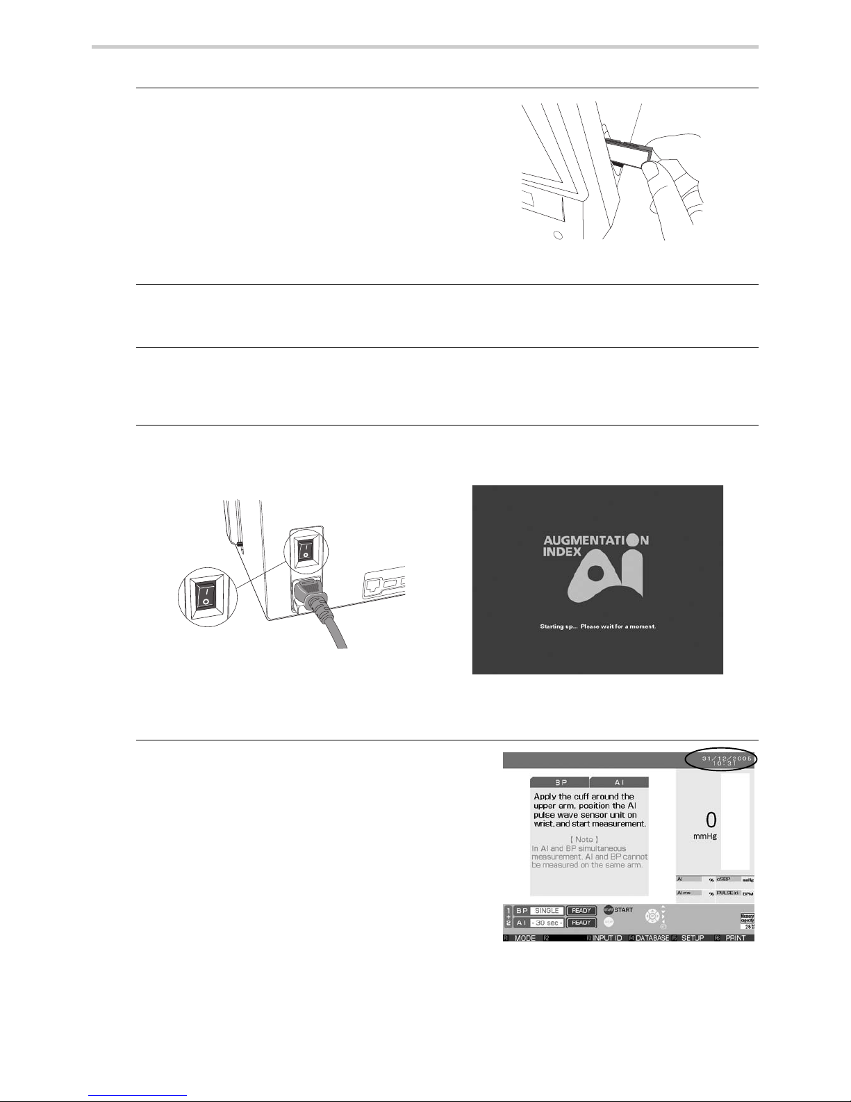
Turning on the power, and checking the time/date
7. Insert the memory card into the slot on the right side
of the main unit.
All measurement data will be saved to the memory
card. The measurement results will not be saved if
the memory card is not properly inserted in or if
there is insufficient memory available on the card.
Note that since the file system takes up 7MB of
memory, the available space on a new card will be
slightly less than the total card memory. [Fig. 6]
8. Load the printer paper.
(Refer to 8.5. “Loading Printer Paper”.)
9. Plug the female end of the power cord into the back of the main unit. Then plug the male
end of the power cord into an electrical outlet with grounding.
10.Press the “I” end of the power switch at the back of the main unit. [Fig. 7]
(After displaying “Starting up.... Please wait fo r a moment” for approximately 30 seconds,
the measurement screen will appear.) [Fig. 8]
11.Check to be sure the time displayed on the upper
right corner of the screen is correct.
If necessary, see the following page for instructions
on how to set the time or date. [Fig. 9]
[Fig. 6]
[Fig. 8]
[Fig. 7]
[Fig. 9]
Page 19
19
8.General Preparation
EN
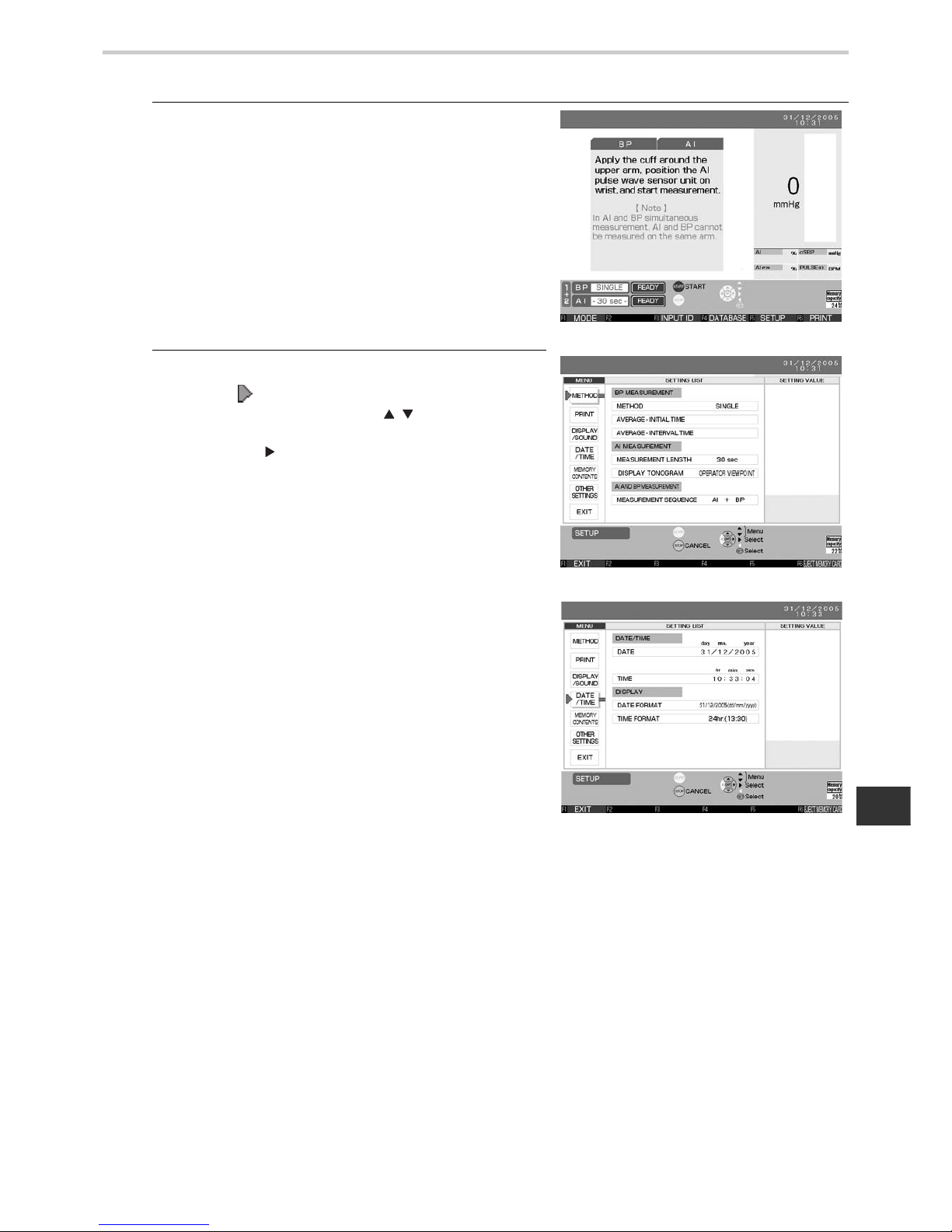
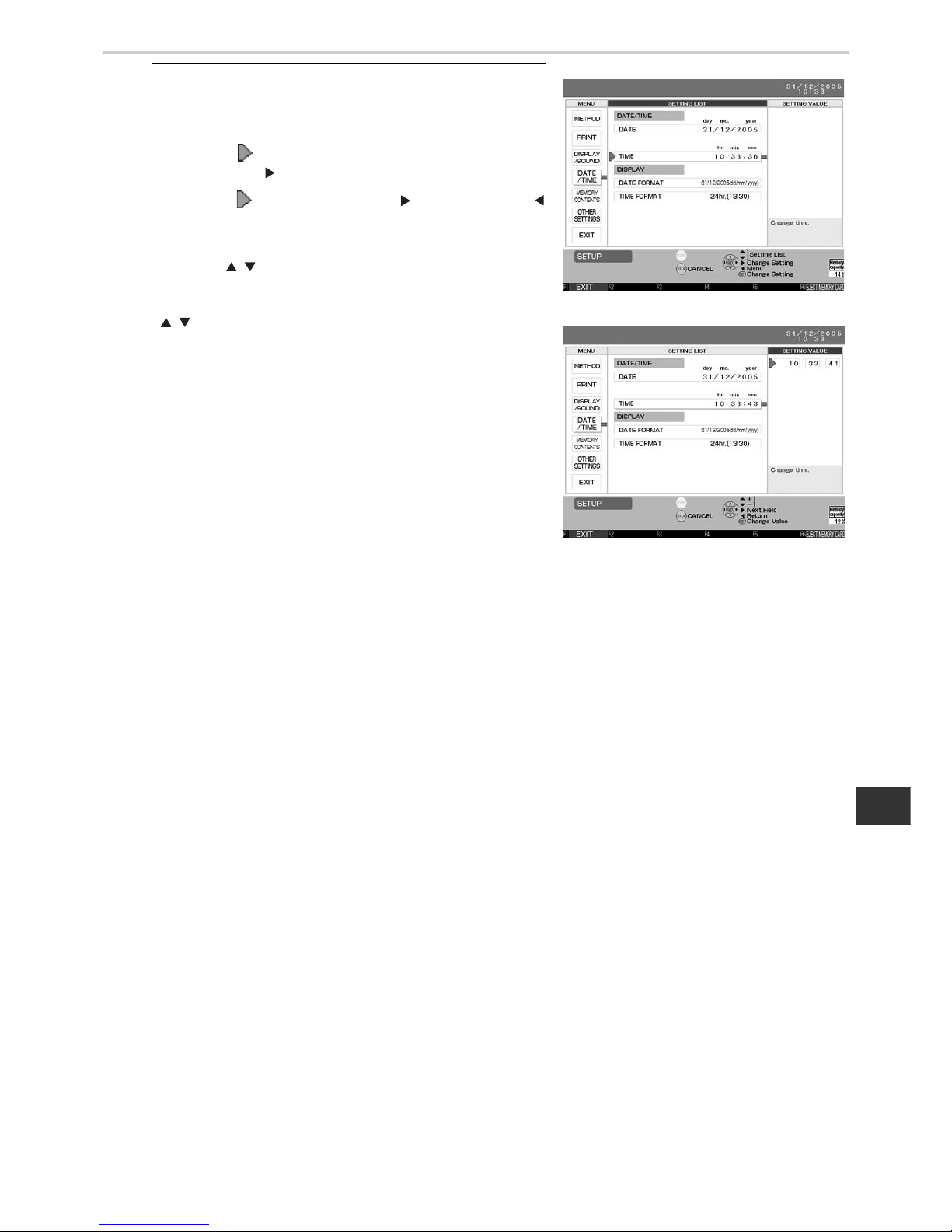
8.3. Setting the Date and Time
1. Press the F5 key on a screen where F5 [SETUP]
appears at the bottom. [Fig. 1]
2. The setup screen will be displayed.
Move the [ ] cursor in the upper-left part of the
screen up or down using the [ ] buttons to select
“DA TE/TIME” from the menu column. Press the SET
button or the [ ] button to move the cursor to the
right. [Figs. 2 and 3]
[Fig. 1]
[Fig. 2]
[Fig. 3]
Page 20
20
8.General Preparation
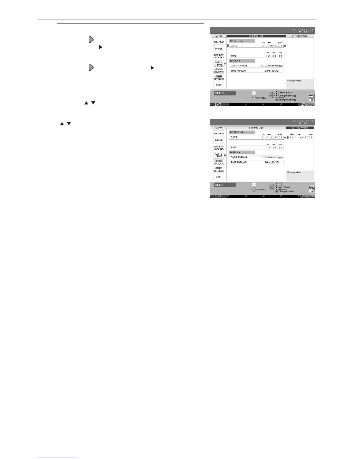
3. To change the [DATE] under [DATE / TIME]:
Move the [ ] cursor to [DATE] and press the SET
button or the [ ] button. [Fig. 4]
Move the [ ] cursor using the [ ] button to select
the item (day/month/year) under [SETTING VALUE]
to change. [Fig. 5]
Use the [ ] buttons to change the setting value.
[ ] These buttons increase and decrease the
values for day, month and year. The year setting
range is from 2005 to 2030.
Press the SET button to accept the selected values.
The date format can be changed. (Refer to Section
18.6.)
[Fig. 5]
[Fig. 4]
Page 21
21
8.General Preparation
EN
4. Follow these steps to change the [TIME] under
[DATE / TIME]:
Change the time.
Move the [ ] cursor to [TIME] and press the SET
button or the [ ] button. [Fig. 6]
Move the [ ] cursor using the [ ] button or the [ ]
button to select the item (hour/minute/second) under
[SETTING VALUE] to change. [Fig. 7]
Use the [ ] buttons to change the setting value.
[ ] These buttons increase and decrease the
values for hour, minute and second.
Press the SET button to accept the selected values.
The clock will resume as soon as the SET button is
pressed. To accurately set the clock to the correct
time, set it slightly in advance and press the SET
button as soon as the set time becomes the current
time.
Press the F1 [EXIT] key to go back to the
measurement screen.
[Fig. 6]
[Fig. 7]
Page 22

22
8.General Preparation
8.4. Setting the Blood Pressure/AI Measurement Method and Registering
ID Information
1. Setting the Blood Pressure/AI Measurement Methods
There are three methods for blood pressure measurement: Single, Average - 2 times, and
Average - 3 times.
The default setting is [SINGLE].
To change this setting, follow the instructions in Section 18.3.
When measuring AI, the duration can be set to any of the following: 15 seconds, 30
seconds, 1 minute, or 3 minutes.
The measurement time set here is the duration of the pulse wave sampling. The total time
required for measurement is slightly longer.
The default setting is [30] seconds.
To change this setting, follow the instructions in Section 18.3.
2. Registering the patient’s ID
Register the patient’s ID before beginning measurement to continuously track trends/
transitions in the measurement results.
Follow the procedure outlined in Section 17.1. to register the ID information.
Page 23
23
8.General Preparation
EN
8.5. Loading Printer Paper
1. Press the release button at the top of the main unit to open the printer cover.
[Figs. 8 and 9]
2. Load the specially designed printer paper into the holder in the direction shown in the
diagram. [Fig. 10]
3. With a small amount of paper sticking out, push the cover closed until it locks into place.
[Fig. 11]
[Fig. 9]
[Fig. 8]
Load the printer paper as shown in the diagram.
*Pull out the paper so that it protrudes from the
printer cover when closing.
When loading a new roll of paper, pull the end out
about 25 cm (10 inches). The end of the roll is sealed
with glue, which does not make a suitable printing
surface.
* Make sure you use OMRON printer paper, refer to Section 5.2.
[Fig. 10]
*When the power is on, the paper will
automatically advance and cut.
[Fig. 11]
Printed side up
Page 24
24
9.Measurement Preparation
9. Measurement Preparation
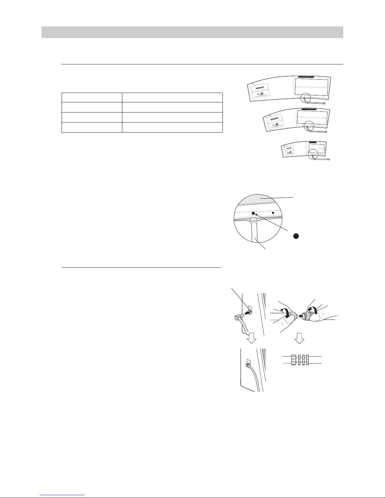
9.1. How to Apply the Blood Pressure Cuff
1. Select a cuff according to the circumference of the
patient’s arm. [Fig. 1]
* Use an appropriate cuff according to the circumference
of the patient’s arm.
* If an inappropriate cuff size is used, the device might
not measure blood pressure accurately.
* Check before wrapping the cuff that:
1.The bladder is set inside the cuff.
2.The tube is not twisted in the cuff.
3.The tube of the bladder emerges from the cuff as
shown in the figure at right. [Fig. 2]
2. Connect the air tube firmly.
* When connecting the air tube to the main unit, connect
the air tube plug firmly into the air connector as shown
in [Fig. 3].
* Connect the air tube and the cuff / bladder set by turning
as shown in [Fig. 4].
* A total air tube length of 1.5 m is provided with the Air
Tube (HEM-9T1.3) in the package.
Arm circumference Name of the arm cuff
17 - 22cm Small size adult arm cuff
22 - 32cm Medium size adult arm cuff
32 - 42cm Large size adult arm cuff
INDEX
ART.
RANGEMIN
MAX
32
~
42cm
(
13"
~
17"
)
REF
HEM
CL19
RANGE
MIN
MAX
INDEX
ART.
22
~
32cm
(
9"
~
13"
)
REF
HEM
CR19
ART.
RANGEMIN
MAX
INDEX
REF
HEM
CS19
17
~
22cm
(
7"
~
9"
)
TUBE
TUBE
TUBE
ART.
TUBE
TUBE
Air Connector
Air tube plug
Air tube sideCuff side
Closeup of the O part
[Fig. 1]
[Fig. 2]
[Fig. 3]
Air tube
Cuff
[Fig. 4]
Where the air
tube emerges
Large size adult arm cuff
Medium size adult arm cuff
Small size adult arm cuff
Page 25
25
9.Measurement Preparation
EN
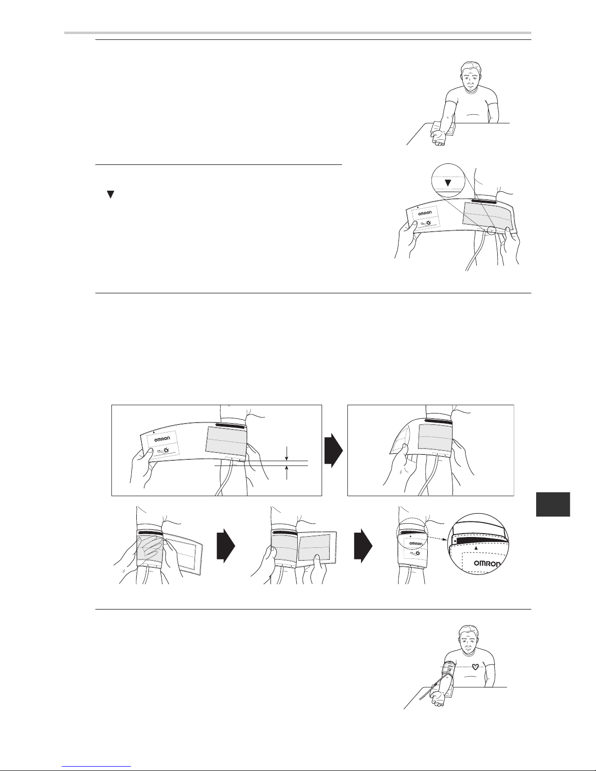
3. Turn the patient’s right palm up. [Fig. 5]
Always wrap the cuff around the upper part of the
patient’s right arm directly on the skin. Wrapping the
cuff around bulky clothing or a rolled-up sleeve can
cause the readings to be inaccurate.
4. Align the brachial artery with the artery position mark
“ ”. [Fig. 6]
5. Wrap firmly with both hands, snug, and make sure to fasten with the hook and loop
fastener. For this step, place the cuf f 1 ~ 2 cm (a little less than one inch) above the inside
of the elbow joint. [Figs. 7-10]
* If after wrapping, INDEX, printed on the cuff, is misaligned with RANGE, select a different, more
appropriate size cuff according to the circumference of the arm, and wrap again.
* If not wrapped with appropriate cuff, the arm might become num b, or the HEM-90 00AI might not be able to
measure blood pressure correctly.
* Wrapping the cuff at an angle will have no impact on the measurements, so allow the cuff to follow the
shape of the arm.
6. Align the cuff to be at the same height as the heart.
* Maintain the height of the cuff at the same height as the
heart in order to measure accurately.
[Fig. 11]
RANGEMIN
MAX
INDEX
ART.
22
~
32cm
(
9"
~
13"
)
REF
HEM
-
CR19
ART.
TUBE
[Fig. 5]
[Fig. 6]
ART.
MIN
INDEX
ART.
22
~
32cm
(
9"
~
13"
)
REF
HEM
-
CR19
RANGE
TUBE
MIN
ART.
RANGE
TUBE
RANGE
ART.
TUBE
ART.
RANGE
TUBE
TUBE
ART.
INDEX
22
~
32cm
(
9"
~
13"
)
REF
HEM
CR19
RANGE
INDEX
RANGE
[Fig. 7]
[Fig. 9]
[Fig. 10]
[Fig. 8]
1~2 cm
ART.
[Fig. 11]
Page 26
26
9.Measurement Preparation
9.2. How to Apply the AI Pulse Wave Sensor Unit
AI measurement is intended only for adults with a wrist
circumference of 10-19 cm around the radius protrusion.
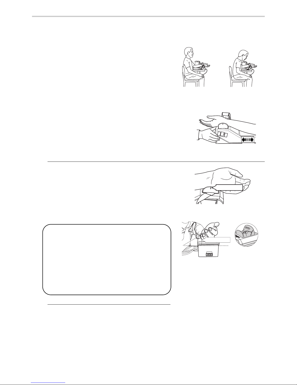
Proper posture
Adjust the height of the chair to align the height of the
wrist with the height of the heart. By sitting back and
keeping the back straight, the arm will naturally be
straight. [Figs. 12 and 13]
* Place the AI pulse wave measurement unit on a flat,
horizontal (non-sloping) surface.
* When measuring with the left arm, place the AI pulse wave
measurement unit on the left side of the patient. (The wrist
rest is set up for a left hand as the initial configuration.) Adjust
the elbow placement board of the AI pulse wave
measurement unit according to the length of the arm of the
patient. (The elbow placement board can be extended
approximately 10 cm) [Fig. 14]
* Instruct the patient to relax and not to move during
measurement.
1. Place the wrist.
Place the thumb on the side of the wrist rest
indicated by the “thumb side” printing on the wrist
rest. [Figs. 15 and 16]
Align the wrinkle of the wrist joint with the wrist
position mark on the wrist rest. [Fig. 15]
* Instruct the patient, saying “relax your hand”. Patient’s palm
will face the front naturally. (It should be a little limp.)
2. Adjust the elbow placement board.
Adjust the elbow placement board of the AI pulse
wave measurement unit according to the length of
the arm of the patient. [Fig. 14]
Good posture Bad posture
Adjust the elbow placement board
[Fig. 12] [Fig. 13]
[Fig. 14]
Wrist position mark
approx 30 degree
[Fig. 15]
[Fig. 16]
The wrist rest has a slope of approximately 30 degrees.
When putting one’s hand along the slope of the wrist rest,
the wrist goes up by a slope of approximately 30 degrees.
* When measuring with the right arm, adjustment of the
wrist rest will be required. Remove the wrist rest from the
top of the AI Pulse Wave Measurement Unit. Turn it so
that the “thumb side” is facing the opposite direction.
Reinsert the wrist rest on the top of the AI Pulse Wave
Measurement Unit. Y ou will now have the correct slope for
a right hand measurement. Tilt the wr ist to turn the thumb
up.
Page 27
27
9.Measurement Preparation
EN
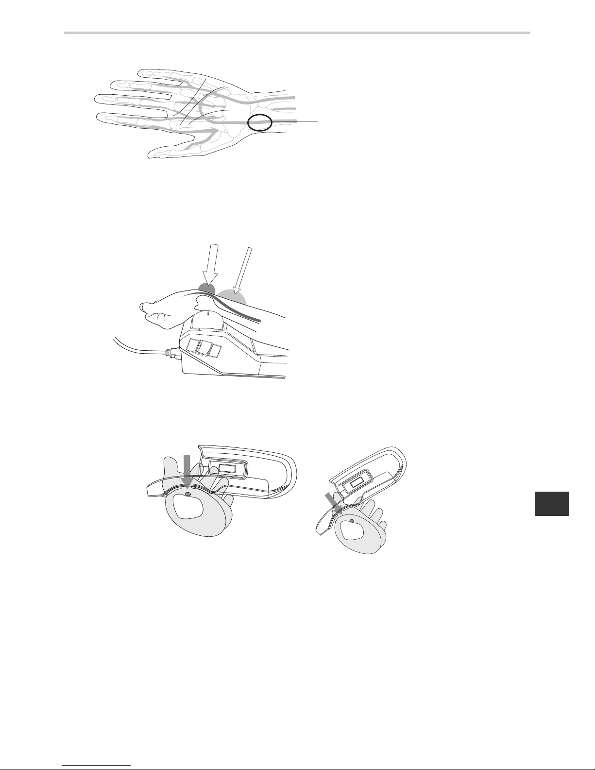
The Best Points for Taking an AI Measurement
The best point is right next to the radius protrusion where the pulse is the strongest. If it is not possible to locate the
radius protrusion, the best point is where the pulse feels the stronge st in the area wher e the bone is clo se to the skin
and is hard to the touch.
Once a point for taking a reading is located, att ach the AI pulse wave sensor unit snugly to the wrist allo wing no gap
to form between the unit and the wrist.
With the palm up, take the reading from the
artery next to the protrusion of the radius on the
thumb side.
[Fig. 18]
Even if the pulse is strong but the bone is not
close to the skin, the blood vessel may be hard
to access, making it difficult to apply pressure.
Poorly-positionedWell-positioned
[Fig. 19]
Poorly-positioned
Well-positioned
[Fig. 20]
Page 28
28
9.Measurement Preparation
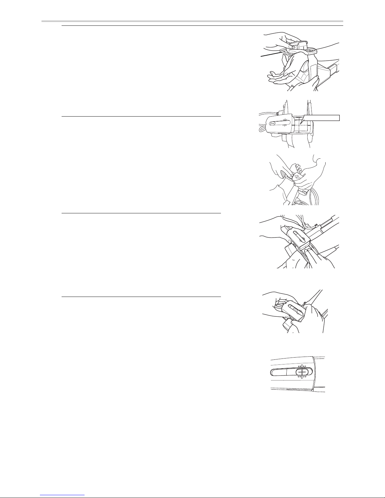
3. Locate the radial artery by palpation.
Once you have located the radial artery, use a
commercially-available, non-permanent felt tip
marker to mark the spot on the artery which will be
best for your AI pulse wave measurement.
A proper measurement can only be done over the
bone at the radial artery.
4. Attach the AI pulse wave sensor unit.
Remove the pulse wave sensor unit from its storage
clip and centre the two intersecting black lines on the
sensor unit frame (the point where the reading is
taken) over the wrist artery spot you marked in 3.
above. Align the wrist wrinkle just below the palm
with the inner edge of the frame. Use the hook and
loop fastener to hold the unit in place. [Figs. 21-22]
5. Confirm the artery’s position again.
Confirm if the AI pulse wave sensor unit frame’s
black lines intersect the artery by palpation.
[Figs. 23-24]
* Instruct the patient to relax and not to move.
* If misaligned, go back to 4. above.
6. Adjust the sensor. [Figs. 25 and 26]
Adjust the AI pulse wave sensor by pressing in the
slide stoppers on both sides.
Continue moving the AI pulse wave sensor until the
black line on the AI pulse wave sensor is aligned
with the centre (longest) line of the AI pulse wave
sensor unit’s outer shell.
* The AI pulse wave sensor unit can be moved slightly by
pressing the slide stoppers at both sides.
* Return the AI pulse wave sensor to its original position
after measurement.
AI measurement point
Storage clip
Align the centre line of the outer shell and
the black line on the sensor unit.
[Fig. 21]
[Fig. 22]
[Fig. 23]
[Fig. 24]
[Fig. 25]
[Fig. 26]
Page 29
29
10.Post - Measurement
EN
10.Post - Measurement
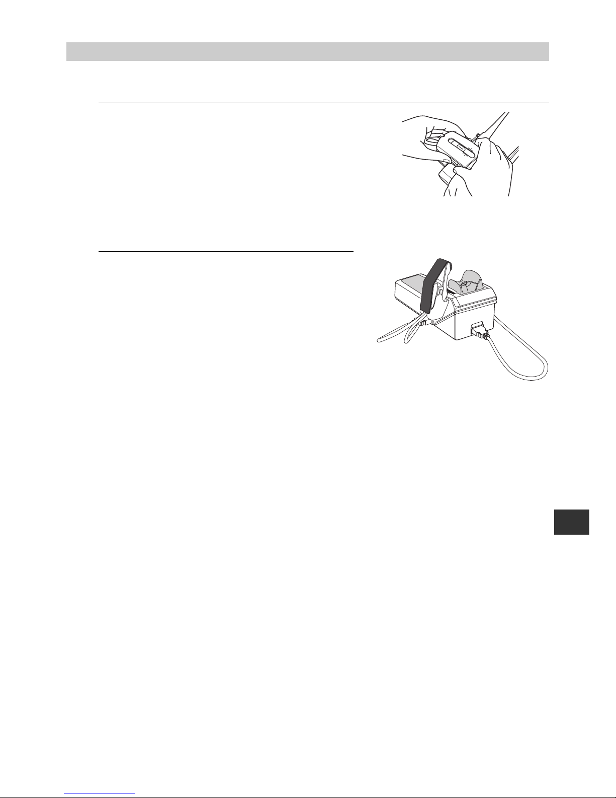
10.1. How to Remove the AI Pulse Wave Sensor Unit
1. Check that measurements are complete. [Fig. 27]
Push down the slide stoppers on both sides and
return the sensor to its original position. Put the AI
pulse wave sensor back in the storage clip.
2. Remove the fastener from around the subject’s
wrist, and store. [Fig. 28]
Attach the protection cap back on the sensor when it
is stored.
[Fig. 28]
[Fig. 27]
Page 30

30
11.Selecting the Measurement Method
11.Selecting the Measurement Method
11.1. Selecting the Measurement Method
This device has the following three measurement options: AI + blood pressure measurement (1.
below), blood pressure measurement (2. below), and AI measurement (3. below). Change the
measurement option by pressing the F1 key [MODE] until the desired option is selected [Figs. 2932].
1. Measuring both AI and blood pressure. (Refer to
Section 12.1.)
The AI and blood pressure can be measured either
automatically, alternating between the two
measurements (AI→BP measurement), or almost
simultaneously using both arms (AI+BP
simultaneous dual-arm measurement).
(Refer to Section 18.3.)
2. Measuring Blood Pressure Only. (Refer to Section
13.1.)
3. Measuring AI Only. (Refer to Section 14.1.)
[Fig. 29]
[Fig. 30]
[Fig. 31]
[Fig. 32]
Page 31

31
12.AI + Blood Pressure Measurement
EN
12.AI + Blood Pressure Measurement
12.1. Measuring AI + Blood Pressure Together
This section explains how to simultaneously measure AI and blood pressure using both arms.
To measure AI and blood pressure alternately, follow the instructions in Section 18.3. to change the
AI measurement sequence.
1. Apply the AI pulse wave sensor unit to the left wrist
and the cuff to the right arm. (Refer to Section 9.)
Make sure the patient’s name and ID are displayed
at the upper left corner of the screen. [Fig. 1]
2. If nothing is displayed, follow the instructions in
Section 17. to register or retrieve the ID information.
If the ID information is not registered, only the date, time and
results will be saved.
Check that the BP and AI measurement methods in
the lower-left part of the screen are both displayed.
3. Press the START button to start measurement.
[Fig. 2]
Inflation of the sensor unit will begin.
Inflation of the cuff will begin after AI pulse wave
sensor pressure becomes stable.
* If you wish to stop during measurement, press the STOP
button. Deflation will occur rapidly.
* When measurement takes more than 5 minutes, the device
will automatically stop.
* Pressing the DISPLAY button during measurement will stop
the measurement and turn off the screen.
4. Make sure the tonogram in the top middle of the
screen rises and forms a triangle. [Fig. 3]
(The continuous pulse waves are displayed at the lower
left corner of the screen.)
[Fig. 1]
[Fig. 2]
[Fig. 3]
Tonogram
Do not press the START (Start measurement) button
without applying the AI pulse wave sensor unit. In
addition, do not press the ST ART (S t art measurement)
button without wrapping the blood pressure cuff. Do
not allow the AI pulse wave sensor unit to slip during
AI pulse wave measurement.
Page 32

32
12.AI + Blood Pressure Measurement
How to incorporate the Tonogram display for a more accurate measurement: A tonogram shows
the output of an AI pulse wave sensor . The positional relationship of the AI pu lse wave senso r and
an artery can be estimated from a tonogram. [Fig. 4]
The values around the peak of the tonogram (around the centre of an artery) are calculated.
The centre peak represents the ideal measurement. Measurement is also possible with an
ascending line to peak or a descending line from peak (see above); however , it is also possible that
an accurate pulse wave may not be taken. If only one outer indicator light is on, reattach the AI
pulse wave sensor and measure again.
Measurement is impossible if the tonogram shows an ascending, descending or flat line (see
above). When re-measuring with an ascending or descending line, it is possible to adjust the
position of the AI pulse wave sensor by sliding it instead of having to remove and reattach the unit.
The artery is located in the direction of the LED lights that are lit. While pressing in the slide
stoppers, adjust the pulse wave sensor by one or two scale unit s (black line s on the casing) in that
direction.
* The Tonogram display has two options; Operator View and Patient View. (Operator View is
selected by default). You can change the setting depending on which way the monitor is facing.
Refer to section 18.3. for more detail.
Slide toward "A"
by one or two
scale units.
Measuring on the
"A" side of the
sensor
Measuring on the
"B" side of the
sensor
Acceptable for measurement
Slide toward "B"
by one or two
scale units.
Readjust the sensor.
(Refer to
Section 9.2.)
B
A
B
A
B
A
B
A
B
A
BABABABABABA
[Fig. 4]
Page 33

33
12.AI + Blood Pressure Measurement
EN
5. As the AI pulse wave sensor pressure becomes
stable, the pulse wave will be displayed in the upper
left corner of the screen, and the actual
measurement will begin. [Fig. 5]
Instruct the patient not to move during
measurement. A measurement error will occur as a
result of body movement or vibration.
If the AI value goes outside of the 30%-150% range,
the AI measurement results will not be displayed for
that beat. Check to make sure that there is no
abnormality in the pulse waveform. This will also
cause a break in the graph of the AI values plotted
for each pulse wave.
If the pulse is irregular or too faint, the device may
not detect the pulse wave, in which case there will
be no pulse waveform and nothing will be displayed
on the graph.
A green bar in the lower-left part of the screen shows
the measurement progress toward completion.
6. Once measurement is complete the results will
appear, along with a light blue “complete” message
at the lower left corner of the screen. Next, the green
message [SA VING] will be displayed at the lower left
corner of the screen. Measurement data will be
stored in the memory card. [Fig. 6]
[Fig. 5]
Measurement progress bar
[Fig. 6]
Do not insert or remove the memory card during the
save operation. This will result in device failure.
Page 34

34
12.AI + Blood Pressure Measurement
7. A beep will sound* when the data has been saved.
The dark blue message [COMPLETE] will be
displayed at the lower left corner of the screen.
[Fig. 7]
The representative pulse wave (AVG) displayed on
the screen is selected among all detected pulse
waves. It has a stable pulse wave and the closest AI
value to the average. Still, there may be some
difference between AVG and the average.
*The beep will not sound if it is set to OFF using the
settings menu.
* The symbols displayed on the left side of cSBP are defined as follows:
[+] AI and blood pressure are simultaneously measured.
[#] A blood pressure fluctuation is detected. Measurement results may be compromised.
[*] The BP value has been manually entered or edited.
* cSBP is displayed only when AVG (representative pulse wave) is selected to display.
AI value and pulses for each
pulse wave (last 20 pulses)
Number of sampled
pulse waves
Pulse waveform
Pulse wave number
Histogram of AI value
for each pulse wave
Current time
Systolic blood
pressure
Diastolic blood
pressure
Pulse pressure
Pulse rate when
using AI sensor
cSBP*
AI value
AI value
normalized to a
pulse rate of 75
Pressure at peak
of reflected wave
“Measurement Complete” screen
[Fig. 7]
Tonogram and measurement
channel during measurement
Pressure value of the AI
pulse wave sensor during
measurement
Standard deviation
Page 35

35
12.AI + Blood Pressure Measurement
EN
Press the [ ] buttons to display results from each
pulse wave measurement.
Example: If 35 waveforms are measured:
34/35 35/35 AVG 1/35 2/35
The pulse wave number is displayed below the
waveform (in the left centre part of the screen).
[Fig. 8]
cSBP is displayed only when AVG is selected to
display.
8. Press the START button to continue measuring. At
this time, the message “Start measurement with the
same ID?” will be displayed. Select “Yes” or “No”.
Select the START button [Yes] to begin
measurement.
Select the STOP button [No] to erase the ID and
return to the default screen. Enter the ID for the next
patient.
Select the F1 key [CANCEL] to return to the
previous screen and change the measurement
mode. [Fig. 9]
[Fig. 8]
[Fig. 9]
Pulse wave number
When the waveform is deformed or inflation is judged to
be incorrect, an error message will appear on screen
(E04 - E08, E73 - E82). In this case, measure again.
Refer to Section 21.
An error message window appearing in the middle of the
screen can be closed by pressing any button.
Page 36

36
13.Blood Pressure Measurement
13.Blood Pressure Measurement
13.1. Blood Pressure Measurement
This mode is for using the device solely as a blood pressure monitor. There are three blood
pressure measurement options: [SINGLE], [AVERAGE - 2 TIMES], [AVERAGE - 3 TIMES]. Refer
to Section 18.3. [SINGLE]: Measures blood pressure only once and displays the results.
[AVERAGE - 2 TIMES]: After the results of the first measurement are displayed, the second
measurement will be performed automatically after the set time interval has elapsed. After
measurement is complete, the average value is displayed. [AVERAGE - 3 TIMES]: Three
sequential measurements are taken and the a verage value is displayed.
Please note - when average
mode is used, only the average can be saved to the dat abase/memory card. If you stop mea surement before
the average is reached, no measurement will be saved to the database/memory card.
1. Apply the cuff.
(Reference to Section 9.1.)
2. Make sure that the number of blood pressure
measurements displayed at the lower left corner of
the screen (see Fig. 2 - BP Single stands for a single
BP measurement) is the same as the number of
measurements you selected (in the case below, the
user selected a single measurement). Make sure
that the patient’s name and ID are displayed at the
upper left corner of the screen. If they are not
displayed, enter or retrieve the patient’s ID data
according to the description starting in Section 17.
3. Press START button and start measuring. [Fig. 1]
* Do not press the START (Start measurement) button without
wrapping the cuff.
* When you want to stop during measurement, press the STOP
button. The cuff will rapidly deflate.
Manual Inflation.
* Holding the START button down during inflation switches to
manual inflation. During manual inflation, inflation only occurs
while the START button is pressed. [Figs. 2 - 4]
* Pressing the DISPLAY button during measurement will stop
the measurement and turn off the screen.
4. The pressure will begin to decrease once the
optimal pressurization value is reached.
After the pressure begins to decrease and
[INFLATE] is displayed, re-inflation will occur only
while the START button is held down.
[Fig. 2]
[Fig. 3]
[Fig. 4]
[Fig. 1]
Page 37

37
13.Blood Pressure Measurement
EN
5. The pulse wave level is displayed with a bar during
measurement. [Fig. 5]
6. Once measurement is
complete the buzzer will
sound* and the results will
appear. [Fig. 6]
Deflation is automatic. Upon
completion, a “COMPLETE”
message will appear in the
lower-left part of the screen.
The buzzer will not sound* if it
is set to OFF in the settings
menu.
7. Press the START button to continue measuring. At
this time, the message “Start measurement with the
same ID?” will be displayed. Select “Yes” or “No”.
Select the START button [Yes] to begin
measurement.
Select the STOP button [No] to erase the ID and
return to the default screen. Enter the ID for the next
patient.
Select the F1 key [CANCEL] to return to the
previous screen and change the measurement
mode. [Fig. 7]
[Fig. 5]
[Fig. 6]
Systolic blood
pressure value
Diastolic blood
pressure value
Pulse
Pulse pressure
[Fig. 7]
When the measurement or inflation are judged to be
incorrect, an error message (E04 – E08) will be
displayed.
In this case, measure again. Refer to Section 21.
An error message window appearing in the middle of
the screen can be closed by pressing any key.
Page 38

38
13.Blood Pressure Measurement
13.2. Auscultation
When selecting blood pressure measurement, it is possible to take the reading using auscultation.
1. Apply the blood pressure cuff around the patient’s
arm. [Fig. 1]
2. Press the F2 key [AUTO MANU] on the blood
pressure measurement screen to bring up
[MANUAL] on the display. [Figs. 2 and 3]
Check that the measurement method display in the
lower-left part of the screen is set to [MANUAL].
3. Place the stethoscope on the patient’s arm.
4. Press the START button. Inflation begins. [Fig. 4]
* Do not press the START button without applying the cuff.
* When you want to stop during measurement, press the STOP
button. The cuff rapidly deflates.
Operator - controlled (Manual) Inflation.
* Holding the START button down during inflation switches to
manual inflation. During manual inflation, inflation only takes
place while the START button is pressed.
[Fig. 2]
[Fig. 3]
[Fig. 4]
[Fig. 1]
Page 39

39
13.Blood Pressure Measurement
EN
5. The pressure will begin to decrease once the
optimal pressurization value is reached. [Fig. 5]
* Once deflation has started, you can reinflate by pressing
START (Start measurement) button.
* If you wish to facilitate deflation after deflation has started,
press the F1 key [DEFLATE]. It facilitates deflation by
approximately 5 - 10 mmHg each time it is pressed.
6. The strength of the pulse wave is displayed (Pulse
Wave Level) with a bar during measurement. [Fig. 6]
7. Deflation continues until finished, followed by a
return to the initial screen. [Fig. 7]
[Fig. 5]
[Fig. 6]
[Fig. 7]
Page 40

40
14.AI Measurement
14.AI Measurement
14.1. AI Measurement
This mode measures only AI.
1. Attach the AI pulse wave sensor unit to the left wrist. (Refer to Section 9.2.)
2. Check that the patient's name and ID appear in the
upper-left part of the screen. [Fig. 1]
If nothing is displayed, follow the instructions in Section
17. to register or retrieve the ID.
If the ID information is not registered, only the time and
results will be saved. Check that the measurement
method in the lower-left part of the screen is set to AI
measurement.
* Do not press the START button without first attaching the AI
pulse wave sensor unit.
* Do not slide the AI pulse wave sensor unit while AI
measurement is in progress.
3. Press the START button. [Fig. 2]
The AI pulse wave sensor unit will begin applying
pressure.
To stop the device once measurement has begun, press
the STOP button. Rapid deflation will occur.
If measurement takes more than five minutes, the device
will stop automatically.
Pressing the DISPLAY button during measurement will
stop the measurement and turn off the screen.
4. Check that the tonogram in the upper-centre part of
the screen is rising and forming a mound shape.
[Fig. 3]
(Refer to Section 12.1.)
(A continuous pulse wave is displayed on the graph in the
lower-left part of the screen.)
[Fig. 1]
[Fig. 2]
[Fig. 3]
Tonogram
Continuous Pulse Wave Graph
Page 41

41
14.AI Measurement
EN
5. The applied pressure will become constant and a pulse
wave will form in the upper-left part of the screen. Instruct
the patient not to move while the measurement is in
progress. Body movements and vibrations can cause a
measurement error to occur. [Fig. 4]
If body movement or vibrations cause a measurement error the
measurement will automatically stop. (Refer to Section 21.)
If the AI value goes outside of the 30%-150% range, the AI [Fig. 4]
measurement results will not be displayed for each beat. Check to
make sure that there is no abnormality in the pulse waveform. This
will also cause a break in the graph of the AI values plotted for each
pulse wave.
If the pulse is irregular or too faint, the device may not detect the
pulse wave, in which case there will be no pulse waveform and
nothing displayed on the graph.
A green bar in the far lower-left part of the screen shows
measurement progress toward completion.
6. Once measurement is complete the results will appear.
[Fig. 5]
The green “SA VING” message will appear in the lower-left
part of the screen and the data will be recorded on the
memory card.
Do not eject the memory card while save is in progress. This
could result in damage to the device.
7. The beep to indicate that the data has been saved will
sound and the dark blue message “COMPLETE” will
appear in the lower-left part of the screen. [Figs. 6 and 7]
The representative pulse wave (AVG) displayed on the screen
is selected among all detected pulse waves. It has a stable
pulse wave and the closest AI value to the average. Still, there
may be some difference between AVG and the average.
[Fig. 4]
[Fig. 5]
[Fig. 6]
Pulse rate when
using AI sensor
AI value
AI value
normalized to a
pulse rate of 75
AI value and pulses for each
pulse wave (last 20 pulses)
Standard deviation
Pulse waveform
Number of sampled
pulse waves
Pulse wave number
Histogram of AI value
for each pulse wave
“Measurement Complete” screen
[Fig. 7]
Tonogram and measurement
channel during measurement
Pressure value of the AI
pulse wave sensor during
measurement
Page 42

42
14.AI Measurement
Press the [ ] buttons to display results from each
measurement.
Example: If 35 waveforms are measured:
34/35 35/35 AVG 1/35 2/35
The pulse wave number is displayed below the
waveform (in the centre lower-left part of the
screen). [Fig. 8]
8. Press the START button to continue measuring. At
this time, the message “Start measurement with the
same ID?” will be displayed. Select “Yes” or “No”.
Select the START button [Yes] to begin
measurement with the current ID.
Select the STOP button [No] to erase the ID and
return to the default screen. Enter the ID for the next
patient.
Select the F1 key [CANCEL] to return to the
previous screen and change the measurement
mode. [Fig. 9]
[Fig. 8]
[Fig. 9]
Pulse wave number
If during measurement the waveform becomes
irregular or it is determined that the pressurization
value is incorrect, an error message will appear on
screen (E73 - 82). In this case, measure again.
Refer to
Section 21. An error message window
appearing in the middle of the screen can be
closed by pressing any button.
Page 43

43
14.AI Measurement
EN
14.2. Changing Magnification and Scroll Speed
Changing the Continuous Pulse Wave Graph Magnification during AI Measurement: Press the
[ ] keys to change the continuous pulse wave graph magnification.
The default display is standard magnification [x1] The setting can be switched from among four
options.
Once magnification is changed, subsequent data will be displayed with the new magnification.
Changing Scroll Speed during AI Measurement.
The default continuous pulse wave scroll speed is 12.5 mm/sec.
Press the [ ] button to change the scroll speed. The setting can be switched from among two
options. When changing scroll speed, subsequent data will be displayed with the new scroll speed.
Magnification x2 x1 x2/3 x1/2
Scroll speed 25 mm/s 12.5 mm/s
Display time
Full Scale (sec)
48
Page 44

44
15.Print
15.Print
15.1. Printing Measurement Results
When [F6 PRINT] is displayed as a function key, you can print the contents of the screen by
pressing the F6 key. You can print measurement results after each measurement is completed, or
after retrieving the measurement results.
A red line appears on the printer paper when only 50 cm are left (about 2 measurements of
AI+BP). Prepare a new roll of paper.
Automatic printing after measurement is an option. (Refer to Section 5.2. for printing option.)
1. After completing a measurement, press the F6 key
[PRINT] while the screen displays the measurement
results. [Fig. 1]
To retrieve data from memory, press the F4 key
[DATABASE] and use the [ ] buttons to select
the data to print. After pressing the SET button to display
the measurement results, press the F6 key [PRINT] to
print. (Refer to Section 16.)
The paper will automatically be fed and cut.
Storing Printed Results
If the printed results need to be stored for a long period of time, it is best to make and store a
photocopy of the printout.
Since the main unit printer uses thermal paper, printed results may fade partially or completely
over time.
Screen displaying the measurement result by [AI
AND BP MEASUREMENT].
[Fig. 1]
Page 45

45
15.Print
EN
Blood pressure:
diastolic value
Example: Print [AI AND BP MEASUREMENT] results [Fig. 2]
Pulse pressure
Pressure at peak
of reflected wave
[Fig. 2]
Blood pressure:
systolic value
* When the BP value
is manually input, [*]
will be displayed.
Waveform
displayed on the
screen
AI value
nomalized to a
pulse rate of 75
Date/time of
measurement
Pulse rate when
using AI sensor
cSBP
AI value
Example: Print [AI measurement] results [Fig. 3]
*
The print format is the same as [AI AND BP
MEASUREMENT]. The BP value is left blank.
Example: Print [Single blood pressure measurement] results [Fig. 4]
[Fig. 3]
Graph of average AI by age
Upper:Females
Lower:Males
Note: If the patient’s gender has been entered, only the
appropriate line will be displayed.
Note: The dotted line shows the standard deviation.
Note: If the patient’s birth date has not been entered, the
patient’s data will not be plotted.
Note: If the data to be plotted on the graph is out of range,
[ ] will be displayed.
[Fig. 4]
Tonogram and measurement
channel during measurement
Standard deviation of AI value
Pressure value of the AI pulse
wave sensor during measurement
Number of sampled pulse waves
Hospital Name
Measurement time
Measurement time
Page 46

46
16.Memory Retrieval
16.Memory Retrieval
16.1. Show All Data List
It is possible to retrieve saved results. Also, trend graphs for each patient can be displayed and
blood pressure measurement results can be added and modified. These functions can be used to
manage data for a patient undergoing multiple examinations.
1. Press the F4 key [DATABASE]. [Fig. 1]
The screen of [ALL DATA] will be displayed.
[Fig. 2]
It is sorted in the ascending order of the measurement
date. [DATABASE] is displayed on the F4 key on the premeasurement screens or the measurement result screen.
2. The latest 5 data items are displayed.
The total amount of data and the current dat a number are
displayed on the lower left of the screen.
Use the [ ] keys to scroll up or down among
individual data entries.
Use the [ ] keys to scroll through data in blocks of
five entries at a time.
Align the [ ] cursor with the data to be retrieved and
press the SET button to show details.
It is possible to replace the ID associated with the
measured data. Align the [ ] cursor with the data to
which the ID is to be replaced and press the F3 key
[REPLACE ID]. If data does not already have an ID, it is
possible to add an ID to the data. (Refer to Section 17. for details on how to enter the ID.)
[Fig. 1]
[Fig. 2]
Page 47

47
16.Memory Retrieval
EN
3. Pressing the F1 key [EXIT] returns the user to a pre-measurement screen.
F1 key EXIT
Return to the pre-measurement screen.
F2 key ID SEARCH
Enter the ID search screen.
F3 key REPLACE ID
Enter the ID replacement screen.
F4 key TREND GRAPH
Display trend graphs.
F5 key EDIT BP
Enter the BP value edit screen.
F6 key DELETE DATA
Delete data from database.
SET button
Data Detail
Display the Details screen.
STOP button
CANCEL Return to the default screen.
To move the [ ] cursor up (newer data), use the [ ] button.
To move the [ ] cursor down (older data), use the [ ] button.
To move to the next page (older data), press the [ ] button.
To return to the previous page (newer data), press the [ ] button.
Pressing the [ ] key on the last page will not display the top page.
Page 48

48
16.Memory Retrieval
16.2. ID Search
The registered ID numbers can be used to search for a specific patient’s measurement results.
1. Press the F2 key [ID SEARCH] on the [DATABASE-
ALL DATA-] screen. [Fig. 3]
As a result, the ID search screen will be displayed.
[Fig.4]
2. Input the ID number of the patient that you wish to
find and press the F6 key [SEARCH]. [Fig. 4]
(Refer to “How to Enter Text” in Step 2, Section 17.1. for
details on text entry.)
[SEARCHING ...] is displayed at the lower left hand corner
of the screen.
3. [PATIENT DATA] Up to seven measurement results
for a patient who has the specified ID will be
displayed per page. [Fig. 5]
[PATIENT DATA] is sorted in the ascending order of
the measurement date.
Use the [ ] keys to scroll up or down among
individual data entries.
Use the [ ] keys to scroll through data in blocks of
seven entries at a time.
Align the [ ] cursor with the data to be retrieved and
press the SET button to show details.
4. When the specific ID number is not registered or
when there is no measurement result, the following
message is displayed: [ID not found]. In such a case,
repeat from step 2.
[Fig. 3]
[Fig. 4]
[Fig. 5]
Page 49

49
16.Memory Retrieval
EN
16.3. Delete Data
Stored measurement results can be selected and deleted.
1. Move the [ ] cursor to a data entry you wish to
delete on the [DATABASE-ALL DATA-] or
[DATABASE-PATIENT DATA-]. [Fig. 6]
The total number of data entries and the current data
number are displayed below the data list.
Use the [ ] keys to scroll up or down among
individual data entries.
Use the [ ] keys to scroll through data in blocks of
five or seven entries at a time.
2. Press the F6 key [DELETE DATA]. [Fig. 7]
[Fig. 6]
[Fig. 7]
F1 key CANCEL Cancel deleting
F3 key DELETE Delete the selected data entry.
STOP button
CANCEL
Cancel deleting
Page 50

50
16.Memory Retrieval
16.4. Data Detail
Displays patient’s detailed measurement results.
1. On the [DATA BASE-ALL DATA-] or [PATIENT
DATA] List screens, move the [ ] cursor to a data
entry to access more detailed data from that
measurement. [Fig. 8]
The total number of data entries and the current data number
displayed are shown in the lower left.
Use the [ ] keys to scroll up or down among individual
data entries.
Use the [ ] keys to scroll through data in blocks of five or
seven entries at a time.
2. Press the SET button to display the single
measurement data in detail. [Fig. 9]
Use the [ ] keys to display the results of each measurement pulse wave.
This will be displayed only if pulse wave data is stored.
3. Press the F1 key [EXIT] to return to the initial screen.
Pressing the other function keys results in the actions listed above.
[DATA BASE-ALL DATA-] screen
[Fig. 8]
F1 key EXIT Return to the pre-measurement screen.
F2 key DATA LIST Enter the Data List screen.
F3 key EDIT/REPLACE ID
Edit or replace the ID information (Refer to Section 17.2.
for “Edit” and Section 17.3. for “Replace”.)
F4 key PATIENT DATA Return to the Patient Data List screen.
F5 key EDIT BP
Opens the Blood Pressure Modification screen.
F6 key PRINT
Print the measurement results.
Refer to Section 15.1. for details on printing results.
SET button
Trend Graph Display the trend graph.
STOP button
CANCEL Return to the default screen.
[Fig. 9]
AGE WHEN MEASURED
BIRTH DATE
HEIGHT
MEASUREMENT
INFO.
DATE
NOTES
WEIGHT
BMI
PATIENT INFO.
Page 51

51
16.Memory Retrieval
EN
16.5. Print Continuous Pulse Waves
To print continuous pulse waves from patient’s detailed measurement results, follow the
steps below.
Continuous pulse waves can be printed only if pulse wave data is stored.
(Refer to Section 18.7.)
1. Press the F6 key on the [-DATA DETAIL-] screen.
[Fig. 10]
At this time, “Select print contents” will be displayed.
[Fig.11]
2. Press the F3 key [CONTINUOUS PULSE WAVE].
[Fig. 11]
[Fig. 10]
F1 key CANCEL Return to the previous screen.
F2 key PRINT RESULT
Print the measurement result. (Refer to Section
15.1.)
F3 key
PRINT CONTINUOUS PULSE
WAVE
Print the continuous pulse wave.
[Fig. 11]
Page 52

52
16.Memory Retrieval
3. Change the magnification and scroll speed on the
preview screen if necessary . (Refer to Section 14.2.)
Then press the F3 key [CONTINUOUS PULSE
WAVE]. [Fig. 12]
To stop printing before it has finished, press the F5 key
[CANCEL PRINT].
The paper is fed and cut automatically. Do not pull the
paper until it is cut automatically.
[Fig. 12]
Printed result of an example continuous pulse wave.
[Fig. 13]
Page 53

53
16.Memory Retrieval
EN
16.6. Trend Graph
Identifies trends within an individual patient’s multiple measurements.
1. Press the F4 key [TREND GRAPH] on the [ALL
DATA] or [PATIENT DATA] screens, or press the
SET button on the [DET AILS] screen. A trend over a
1-day time will be displayed. [Fig. 14]
* Data that can be used to display a trend graph is limited
to those patients with IDs.
Press the F5 key [SELECT GRAPH] to change the
display from 1 DAY to 30 DAYS to 360 DAYS to cSBPSBP contrast graph.
* When the number of measurements in a day is quite
large and you display the [DAY] trend graph, the device
will thin out measurement values for you. [Fig. 14]
The [30 DAYS] shows a graph of the measurement
results for the previous 30 days starting from the date of
the selected result. [Fig. 15]
The [360 DAYS] shows a graph of the measurement
results for the previous 360 days starting from the date
of the selected result. [Fig. 16]
Press the [ ]* key to show a graph that is newer than
the date/time of the selected results.
Press the [ ]* button to view a graph that is further in the
past. This will work only if there are measurement results
recorded from before and after the date/time of the
selected results.
When several measurements are taken for a certain
period of time, the data with higher priority will be
displayed on the graph. Only one piece of data every 10
minutes on [1 DAY] graph, one piece of data every 6
hours on [30 DAYS] graph and one piece of data every 3
days on [360 DAYS] graph are automatically selected
and displayed, respectively.
Data is selected in the following priority.
1) data containing a measurement of both blood pre ssure
and AI.
2) data containing a measurement of AI.
3) data containing a measurement of blood pressure.
When multiple pieces of data contain the same type of
data, the newest one will be selected.
When the data contains a measurement of high blood
pressure with more than 200 mmHg, it will be displayed
with
on the graph.
[Fig. 14]
1 DAY
30 DAYS
[Fig. 15]
360 DAYS
[Fig. 16]
cSBP-SBP contrast graph
[Fig. 17]
Page 54

54
16.Memory Retrieval
* These keys will not show for the cSBP-SBP contrast graph.
2. Press the F6 key to print the trend graph or the cSBP-SBP contrast graph. [Fig. 18]
3. Press the SET button to return to the Data Details screen.
4. Press the F1 key to return to the default screen.
You can select whether the trend graph or the cSBP-SBP contrast graph is included every time a
measurement result is printed.
(Refer to Section 18.4.)
F1 key EXIT Return to the pre-measurement screen.
F2 key DATA LIST Return to the Data List screen.
F4 key PATIENT DATA Return to the Patient Data List screen.
F5 key SELECT GRAPH
Change the scale of the trend graph or select PRINT SBP
cb CONTRAST GRAPH
F6 key PRINT
Print the trend graph.
* SET button Data Detail
Display the Details screen.
* key
For selecting from [AI] or [AI P75]
* key
For selecting from [cSBP], [cSBP + ∆SBP] or [∆SBP]
STOP button
CANCEL Return to the default screen.
[Fig. 18]
[Fig. 19]
Page 55

55
16.Memory Retrieval
EN
16.7. Adding and Modifying Blood Pressure Measurement Values
It is possible to modify blood pressure measurement
results from AI blood pressure measurements or add
blood pressure measurement results to AI
measurements.
1. When F5 [EDIT BP] is displayed, it is possible to
enter and modify blood pressure measurement
values. [Fig. 20]
Select the data, using the cursor and press the F5 key
[EDIT BP].
However, it is not possible to modify blood pressure
measurement results obtained in blood pressure
measurement mode. It is not possible to modify AI
measurement results either.
2. Input values for each field on the Manual Blood
Pressure Entry screen. [Fig. 21]
(Refer to “How to Enter Text” in Step 2, Section 17.1. for
details on text entry.)
Each item can be input in the following ranges.
SYS 1-299
DIA 0-298
* If an inappropriate value is input, [This value is out of range]
is displayed. For example, if SYS<DIA the value is out of
range.
3. When you have finished entering data, press the F1
key [SAVE AND EXIT].
(The confirmation message [Do you want to save data?]
will be displayed.) [Fig. 22]
Screen for [ALL DATA LIST BY ID]
[Fig. 22]
[Fig. 20]
[Fig. 21]
Page 56

56
16.Memory Retrieval
4. To complete the entry, press the F2 key [YES]. If you
do not want to save the data, press the F3 key [NO].
To return once again to the Manual Blood Pressure
Entry screen, press the F1 key [CANCEL]. Once you
have pressed the F2 [YES] or F3 [NO], you will be
returned to the DATA BASE - ALL DATA. [Fig. 23]
Manually-input blood pressure values will be
asterisked
[Fig. 23]
Page 57

57
17.Registering ID Information
EN
17.Registering ID Information
17.1. ID Registration
The patient’s [ID], [NAME], [BIRTH DATE], [GENDER] and [NOTES] can be registered in
the ID information screen.
[HEIGHT], [WEIGHT] and [NOTES] can be also added as measurement information.
Once the patient’s ID information is registered, changes in the measurement results can
be tracked continuously.
Register the ID information before taking measurements.
Only one patient is assigned to a specific ID. It is not possible to register two or more patients
under the same ID.
1. Press the F3 key [INPUT ID] on a screen where this
button is displayed. [Fig. 1]
2. The ID Entry screen will appear.
The [ ] cursor will appear next to ID in the left part
of the screen. [Fig. 2]
[Fig. 2]
[Fig. 1]
Page 58

58
17.Registering ID Information
How to Enter Text
Press the [ ] buttons to select the desired
characters.
Press the [ ] button to move the selector up.
Press the [ ] button to move the selector down.
Press the [ ] button to move the selector to the left.
Press the [ ] button to move the selector to the right.
Press the SET button to accept the selected character.
To correct entered text, press the F3 key [CURSOR ]
or the F4 key [CURSOR ] to move the cursor to the
right of the character to be corrected. Press the F5 key
[BACK SP ACE] to delete the incorrect character and then
retype it correctly.
3. How to Register an ID [Fig. 4]
A text selection box will appear in the upper-right
part of the screen. The ID field can be entered using
capital letters, numbers, symbols or spaces. The
field can contain up to 20 characters. You may
choose any combination of characters to create an
ID as long as that ID has not previously been
registered.
Once entry is complete, press the F1 key [SAVE]
and enter the name.
If the ID has already been registered, the cursor will move the
cursor to the name field and the screen will display the name
and other information that has been registered under that ID.
Check to see if the ID needs to be changed or if registration
needs to be redone or corrected. If not, press the F1 key
[SAVE] to go back. If a change is necessary, proceed to the
next field and make the necessary changes.
4. How to Register a Name [Fig. 5]
A text selection box will appear in the upper-right
part of the screen. The name field can be entered
using capital letters, numbers, symbols and spaces.
The field can contain up to 25 characters.
Hereafter , entry automatically moves to the next field
when the maximum number of characters is input.
Once entry is complete, press the F6 key [NEXT
FIELD] to move to the date of birth registration.
[Fig. 3]
[Fig. 4]
[Fig. 5]
Page 59

59
17.Registering ID Information
EN
5. How to Register a Birth Date [Fig. 6]
Enter the month, day and year from the text
selection box.
The cursor will not move to the age field. [Fig. 7]
After entering month, day and year and moving to the next
field, the age will automatically be calculated based on the
current date and the date of birth en te re d .
The earliest possible date of birth that can be entered is
January 1,1900.
Once entry is complete, press the F6 key [NEXT
FIELD] and enter the gender.
6. How to Register a Gender [Fig. 8]
For the gender field, select either “Male” or “Female” from
the text selection box area in the upper-right part of the
screen. Press the SET button to accept the entry and
move onto the next field.
7. How to Register Notes [Fig. 9]
The P A TIENT INFO field can be used for one patient only.
When the entry is modified, it will be reflected in all other
related data including previously measured data.
The notes field can be used as a space for adding
miscellaneous information.
An entry in the notes field is optional.
The text selection box will appear in the upper-right part
of the screen.
The notes field can be entered using capital letters,
numbers, symbols and spaces. The field can contain up
to 18 characters.
If corrections need to be made in any of the fields, press
the F6 key [NEXT FIELD] repeatedly and move the
cursor until it goes to the field that need to be edited.
[Fig. 6]
[Fig. 7]
[Fig. 8]
[Fig. 9]
Page 60

60
17.Registering ID Information
8. How to Register measurement information [Fig. 10]
[HEIGHT], [WEIGHT] and [NOTES] can be entered as
measurement information. You may change to either
metric or English measurements as preferred. Refer to
Section 18.5. for details.
The cursor will not move to the BMI field.
After entering height and weight and moving to the next
field, the BMI will be automatically calculated based on
the height and weight information entered.
Measurement information can be entered for each
measurement.
The field can contain up to 32 characters.
9. Completing Registration
Once the data has been entered for each field, press the
F1 key [SAVE]. [Fig. 11]
Once registration is complete, the default screen appears
and the name displayed in the upper-left part of the
screen will change to the ID that was just registered.
* If the birth date or gender is blank, the confirmation
message will be displayed as the norm table will not be
plotted properly.
[Fig. 10]
[Fig. 11]
Page 61

61
17.Registering ID Information
EN
17.2. Retrieval / Edit ID
It is possible to use a patient’s ID to retrieve registration information if their registration is already
complete.
1. Press the F3 key [INPUT ID] on a screen where this
button is displayed to enter the ID Input screen.
[Fig. 12]
When the F3 key [EDIT ID] is pressed on a screen where
this button is displayed, you will be proceeded to [3].
2. Input the ID and press the F1 key [SAVE]. [Fig. 13]
3. The registration information will be displayed.
When the ID is already registered, [INPUT ID
(Registered)] will be displayed.
If it is not necessary to edit the registration information,
press the F1 key [SAVE]. [Fig. 14]
4. Follow the registration procedure to edit the
registration information. (Refer to Section 17.1.)
If the ID number is changed while the existing registration
information is displayed on the screen, a new ID needs to
be registered. The existing registration information will
remain with the old number.
When the registration information has been edited, press
the F1 key [SAVE]. [Fig. 15]
[Fig. 12]
[Fig. 13]
[Fig. 14]
[Fig. 15]
Page 62

62
17.Registering ID Information
5. Confirm the dialog if it appears and press the F2 key
[SAVE] to register. [Fig. 16]
The screen returns to Step 1, and the ID number will be
shown on the upper-left part of the screen.
[Fig. 16]
Page 63

63
17.Registering ID Information
EN
17.3. Replace ID
It is possible to select the saved measurement results and replace the ID number.
1. Move the [ ] cursor to a data entry you wish to
replace on the [DATABASE-ALL DATA-] or
[DA TABASE-PATIENT DA TA-], and press the F3 key
[REPLACE ID]. [Fig. 17]
2. The ID Entry screen will appear. [Fig. 18]
3. Press the F1 key [SAVE] after an ID is input.
[Fig. 19]
F3 key move one character back
F4 key move one character forward
F5 key delete the previous character
If it is a new ID, it will proceed to ID Registration. Input ID
information. (Refer to Section 17.1.)
4. The screen goes back to [DATABASE-ALL DATA-]
or [DATABASE-PATIENT DATA-], and the new ID
number will be displayed. [Fig. 20]
[Fig. 17]
[Fig. 18]
[Fig. 19]
[Fig. 20]
Page 64

64
18.Configuration Options
18.Configuration Options
18.1. How to Change the Settings
SINGLE
AVERAGE - 2 TIMES
AVERAGE - 3 TIMES
CHECK
0 min
3 min
5 min
10 min
30 sec
1 min
2 min
3 min
15 sec
30 sec
1 min
3 min
PATIENT VIEWPOINT
OPERATOR VIEWPOINT
AI -> BP
AI + BP
METHOD
BP
MEASUREMENT
METHOD
NO PRINT
1 COPY
2 COPIES
3 COPIES
AUTO
PRINT
DISPLAY
TONOGRAM
AVERAGE-
INITIAL TIME
AVERAGE-
INTERV AL TIME
MEASUREMENT
LENGTH
AI
MEASUREMENT
PRINTING
RESULTS
PRINT
AI AND BP
MEASUREMENT
MEASUREMENT
SEQUENCE
NO PRINT
PRINT
PRINT
NORM TABLES
NO PRINT
1 DAY TREND
30 DAYS TREND
360 DAYS TREND
PRINT
TREND GRAPH
NO PRINT
PRINT
PRINT SBP cb
CONTRAST GRAPH
NO PRINT
PRINT
PRINT
MEASUREMENT INFO
YES
NO
PRINT GRAPH-
WHEN NO RECORDS
AI
AI P75
AI PRINT ITEMS
cSBP
∆SBP
cSBP PRINT ITEMS
cSBP + ∆SBP
The default settings are in the shaded boxes.
Page 65

65
18.Configuration Options
EN
1
2
3
4
5
5 min
15 min
30 min
60 min
DISABLE
ON
OFF
cm.kg
ft,in.lbs
6
7
8
DISPLAY
DISPLAY/SOUND
BRIGHTNESS
AUTO OFF TIMER
HEIGHT/WEIGHT
UNIT
SOUND BEEP SOUND
ALL
AVERAGE ONLY
AI
MEASUREMENT
PULSE WAVE DATA
ON
OFF
ALL
MEASUREMENTS
MEMORY ERRORS
2005/12/31
(yyyy/mm/dd)
12-31-2005
(mm-dd-yyyy)
31/12/2005
(dd/mm/yyyy)
12 hr. (1:30pm)
24 hr. (13:30)
DISPLAY
DATE/TIME
DATE FORMAT
TIME FORMAT
[ ]-[ ]-[ ]
[ ]:[ ]:[ ]
DATE/TIME
DATE
TIME
MEMORY
CONTENTS
EXIT THE
SETTINGS
EXIT
CLEAR
SETTINGS
INPUT HOSPITAL
NAME
EJECT
MEMORY CARD
FORMAT
MEMORY CARD
OTHER SETTINGS
Page 66

66
18.Configuration Options
18.2. How to Change the Setup
You can change the HEM-9000AI’s initial setup according to your needs.
Memory card ejection and initialization can also be performed under this setup process.
1. Press the F5 key to enter the [SETUP] screen.
[Fig. 1]
2. The [SETUP] screen is displayed. [Fig. 2]
Move the [ ] cursor using the [ ] buttons to
select from the menu column then press the SET
button or the [ ] button.
When the F1 key [EXIT] or [EXIT] on the menu is pressed, all the changes will be completed. If the
STOP key [CANCEL] is pressed, the changed will be cancelled except the date and hospital name.
[Fig. 1]
Screen of [AI AND BP MEASUREMENT]
[Fig. 2]
Select the
setup menu
Move the [ ]
cursor to the
item you wish
to set.
Select the setup
item’s preferred
setting value
Press the
[SET] button
Page 67

67
18.Configuration Options
EN
18.3. How to Change the Measurement Settings
Blood pressure measurements, AI measurements, AI + blood pressure measurement s and result s
printouts can be changed.
1. Press the F5 key to enter the [SET UP] screen. (Refer to Section 18.2.)
2. Move the [ ] cursor to [METHOD] under the [MENU]
column and press the SET or [ ] button. Move the [ ]
cursor to [SETTING LIST] column. [Fig. 1]
3. To change the [METHOD] under [BP
MEASUREMENT]:
1. Move the [ ] cursor to [METHOD]. [Fig. 2]
[SINGLE], [AVERAGE - 2 TIMES], [AVERAGE - 3
TIMES], and [CHECK] will appear as options under
[SETTING VALUE] column.
2. Press the SET or [ ] button to move the [ ] cursor to
[SETTING VALUE] column. [Fig. 3]
3. Move the [ ] cursor to the desired setting value,
selecting from the options [SINGLE], [AVERAGE - 2
TIMES], or [AVERAGE - 3 TIMES] under [SETTING
VALUE].
The default setting is [SINGLE].
Select [CHECK] as the setting value to calibrate the pressure.
(Refer to Section 19.)
4. Press the SET button to accept the setting value.
5. Press the F1 key [EXIT] to return to the default screen.
4. To change the [AVERAGE - INITIAL TIME] under [BP
MEASUREMENT]: [Fig. 4]
When selecting Average - 2 times or Average - 3 times, it is
possible to set a delay period between the time when the
START button is pressed and the blood pressure is
measured.
1. Move the [ ] cursor to [AVERAGE - INITIAL TIME].
2. Press the SET or [ ] button to move the [ ] cursor to
[SETTING VALUE].
3. Move the [ ] cursor to the desired delay period,
selecting from [0 min], [3 min], [5 min] or [10 min]. [Fig. 5]
The default setting is [0 min].
4. Press the SET button to accept the set value.
5. Press the F1 key [EXIT] to return to the default screen.
[Fig. 1]
[Fig. 2]
[Fig. 3]
[Fig. 4]
[Fig. 5]
Page 68

68
18.Configuration Options
5. To change the amount of time between blood pressure measurements.
When selecting [AVERAGE - 2 TIMES] or [AVERAGE - 3 TIMES], it is possible to set the
interval between blood pressure measurements.
1. Move the [ ] cursor to [AVERAGE - INTERVAL TIME].
[Fig. 6]
2. Press the SET or [ ] button to move the [ ] cursor to
[SETTING VALUE].
3. Move the [ ] cursor to the desired interval, selecting
from [30 sec], [1 min], [2 min] or [3 min].
The default setting is [1 min]. [Fig. 7]
4. Press the SET button to accept the setting value.
5. Press the F1 key [EXIT] to return to the default screen.
6. To change the [MEASUREMENT LENGTH] under [AI
MEASUREMENT]:
1. Move the [ ] cursor to [Measurement Length]. [Fig. 8]
2. Press the SET or [ ] button to move the [ ] cursor to
[SETTING VALUE].
3. Move the [ ] cursor to the desired measurement time,
selecting from [15 sec], [30 sec], [1 min] or [3 min].
[Fig. 9]
The default setting is [30 sec].
The measurement time set here is the duration of the pulse
wave sampling.
The total time required for measurement is slightly longer.
4. Press the SET button to accept the setting value.
5. Press the F1 key [EXIT] to return to the default screen.
[Fig. 6]
[Fig. 7]
[Fig. 8]
[Fig. 9]
Page 69

69
18.Configuration Options
EN
7. To change the [DISPLAY TONOGRAM] under [AI
MEASUREMENT]:
1. Move the [ ] cursor to [DISPLAY TONOGRAM].
[Fig. 10]
2. Press the SET or [ ] button to move the [ ] cursor to
[SETTING VALUE].
3. Move the [ ] cursor to the desired setting, selecting
from [PATIENT VIEWPOINT] or [OPERATOR
VIEWPOINT]. [Fig. 11]
The default setting is [OPERATOR VIEWPOINT].
4. Press the SET button to accept the setting value.
5. Press the F1 key [EXIT] to return to the default screen.
8. To change the [MEASUREMENT SEQUENCE] under
[AI AND BP MEASUREMENT]:
1. Move the [ ] cursor to [MEASUREMENT SEQUENCE].
[Fig. 12]
2. Press the SET or [ ] button to move the [ ] cursor to
[SETTING VALUE].
3. Move the [ ] cursor to the desired setting, selecting
from [AI
→ BP] or [AI + BP] under [SETTING VALUE].
[Fig. 13]
The default setting is [AI + BP].
4. Press the SET button to accept the set value.
5. Press the F1 key [EXIT] to return to the default screen.
[Fig. 10]
[Fig. 11]
[Fig. 12]
[Fig. 13]
Page 70

70
18.Configuration Options
18.4. How to Change Settings for Printing
It is possible to change the content of data to be printed and saved.
1. Press the F5 key to enter the [SET UP] screen.
(Refer to Section 18.2.)
2. Move the [ ] cursor to [PRINT] under the [MENU]
column and press the SET or [ ] button to move the
[ ] cursor to [SETTING LIST]. [Fig. 1]
3. To print the result automatically after measurement:
Move the [ ] cursor to [AUTO PRINT]. [Fig. 3]
1. Press the SET or [ ] button to move the [ ] cursor to
[SETTING VALUE].
2. Move the [ ] cursor to the desired setting, selecting
from [NO PRINT], [1 COPY], [2 COPIES] or [3 COPIES]
under [SETTING VALUE].
The default setting is [NO PRINT].
3. Press the SET button to accept the setting value
4. Press the F1 key [EXIT] to return to the default screen.
4. To print the norm table with measurement results:
1. Move the [ ] cursor to [PRINT NORM TABLES].
2. Press the SET or [ ] button to move the [ ] cursor to
[SETTING VALUE].
3. Move the [ ] cursor to the desired setting, selecting
from [NO PRINT] or [PRINT] under [SETTING VALUE].
The default setting is [PRINT].
4. Press the SET button to accept the setting value.
5. Press the F1 key [EXIT] to return to the default screen.
[Fig. 1]
[Fig. 2]
[Fig. 3]
[Fig. 4]
[Fig. 5]
Page 71

71
18.Configuration Options
EN
5. To print a trend graph with measurement results:
1. Move the [ ] cursor to [PRINT TREND GRAPH].
2. Press the SET or [ ] button to move the [ ] cursor to
[SETTING VALUE].
3. Move the [ ] cursor to the desired setting, selecting
from [NO PRINT], [1 DA Y TREND], [30 DAYS TREND] or
[360 DAYS TREND] under [SETTING VALUE].
The default setting is [NO PRINT].
4. Press the SET button to accept the setting value.
5. Press the F1 key [EXIT] to return to the default screen.
6. To include the cSBP-SBP contrast graph when printing
after measurement:
1. Move the [ ] cursor to [PRINT SBP cb CONTRAST
GRAPH].
2. Press the SET or [ ] button to move the [ ] cursor to
[SETTING VALUE].
3. Move the [ ] cursor to the desired setting, selecting
from [NO PRINT] or [PRINT] under [SETTING VALUE].
The default setting is [NO PRINT].
4. Press the SET button to accept the setting value.
5. Press the F1 key [EXIT] to return to the default screen.
[Fig. 6]
[Fig. 7]
[Fig. 8]
[Fig. 9]
Page 72

72
18.Configuration Options
7. To print measurement information with measurement
results:
What is measurement information includes the following.
•Tonogram and measurement channel during measurement
•Measurement time
•Number of sampled pulse waves
•Standard deviation of AI value
•Pressure value of the AI pulse wave sensor during
measurement
1. Move the [ ] cursor to [PRINT MEASUREMENT INFO].
2. Press the SET or [ ] button to move the [ ] cursor to
[SETTING VALUE].
3. Move the [ ] cursor to the desired setting, selecting
from [NO PRINT] or [PRINT] under [SETTING VALUE].
The default setting is [PRINT].
4. Press the SET button to accept the setting value.
5. Press the F1 key [EXIT] to return to the default screen.
8. To select whether graph is printed when no previous
data exists.
1. Move the [ ] cursor to [PRINT GRAPH - WHEN NO
RECORDS].
2. Press the SET or [ ] button to move the [ ] cursor to
[SETTING VALUE].
3. Move the [ ] cursor to the desired setting, selecting
from [YES] or [NO] under [SETTING VALUE].
The default setting is [NO].
[YES]: Print even when only one piece of data will be
added on the graph.
[NO]: Print only when more than one piece of data will
be added on the graph.
4. Press the SET button to accept the setting value.
5. Press the F1 key [EXIT] to return to the default screen.
[Fig. 10]
[Fig. 11]
[Fig. 12]
[Fig. 13]
Page 73

73
18.Configuration Options
EN
9. To select cSBP items to print on the trend graph:
1. Move the [ ] cursor to [cSBP PRINT ITEMS].
2. Press the SET or [ ] button to move the [ ] cursor to
[SETTING VALUE].
3. Move the [ ] cursor to the desired setting, selecting
from [cSBP], [∆SBP] or [cSBP+∆SBP] under [SETTING
VALUE].
The default setting is [cSBP].
[cSBP]: Display cSBP calculated from
measurement result
[∆SBP]: Display the difference between cSBP and
SBP
[cSBP+∆SBP]:Display both cSBP and ∆SBP
4. Press the SET button to accept the setting value.
5. Press the F1 key [EXIT] to return to the default screen.
10.To print the norm table or a trend graph with AI value
normalized to a pulse rate or 75:
1. Move the [ ] cursor to [AI PRINT ITEMS].
2. Press the SET or [ ] button to move the [ ] cursor to
[SETTING VALUE].
3. Move the [ ] cursor to the desired setting, selecting
from [AI] or [AI P75] under [SETTING VALUE].
The default setting is [AI].
4. Press the SET button to accept the setting value.
5. Press the F1 key [EXIT] to return to the default screen.
[Fig. 14]
[Fig. 15]
[Fig. 16]
[Fig. 17]
Page 74

74
18.Configuration Options
18.5. How to Change Display/Sound Settings
You can change the settings for the display and sound.
1. Press the F5 key to enter the [SET UP] screen. (Refer to Section 18.2.)
2. Move the [ ] cursor to [DISPLAY/SOUND] under the
[MENU] column and press the SET or [ ] button to
move the [ ] cursor to [SETTING LIST]. [Fig. 1]
3. To change the [BRIGHTNESS] under [DISPLAY]
1. Move the [ ] cursor to [BRIGHTNESS]. [Fig. 2]
2. Press the SET or [ ] button to move the [ ] cursor to
[SETTING VALUE].
3. Move the [ ] cursor to the desired setting, selecting
from [1] - [8] under [SETTING VALUE]. 1 is darkest. 8 is
brightest. (The default setting is [5].)
4. Press the SET button to accept the setting value.
5. Press the F1 key [EXIT] to return to the default screen.
4. Changing the [AUTO OFF TIMER] under [DISPLAY]
sets the time before the display automatically turns off
when buttons have not been pressed.
1. Move the [ ] cursor to [AUTO OFF TIMER]. [Fig. 4]
2. Press the SET or [ ] button to move the [ ] cursor to
[SETTING VALUE].
3. Move the [ ] cursor to the desired setting, selecting
from [5 min], [15 min], [30 min], [60 min] or [DISABLE].
(The default setting is [DISABLE].) [Fig. 5]
4. Press the SET button to accept the setting value.
5. Press the F1 key [EXIT] to return to the default screen.
[Fig. 1]
[Fig. 2]
[Fig. 3]
[Fig. 4]
[Fig. 5]
Page 75

75
18.Configuration Options
EN
5. To change the [HEIGHT/WEIGHT UNIT] under
[DISPLAY]:
1. Move the [ ] cursor to [HEIGHT/WEIGHT UNIT].
[Fig. 6]
2. Press the SET or [ ] button to move the [ ] cursor to
[SETTING VALUE]. [Fig. 7]
3. Move the [ ] cursor to the desired setting, selecting
from [cm•kg] or [ft, in.•lbs] under [SETTING VALUE].
The default setting is [cm•kg].
4. Press the SET button to accept the setting value.
5. Press the F1 key [EXIT] to return to the default screen.
6. To change the [BEEP SOUND] under [SOUND]:
1. Move the [ ] cursor to [BEEP SOUND]. [Fig. 8]
2. Press the SET or [ ] button to move the [ ] cursor to
[SETTING VALUE].
3. Move the [ ] cursor to the desired setting, from [ON] or
[OFF] under [SETTING VALUE]. [Fig. 9]
(The default setting is [ON].)
4. Press the SET button to accept the setting value.
5. Press the F1 key [EXIT] to return to the default screen.
[Fig. 6]
[Fig. 7]
[Fig. 8]
[Fig. 9]
Page 76

76
18.Configuration Options
18.6. How to Change the Clock Settings
It is possible to change the date and time settings and display.
1. Press the F5 key to enter the [SET UP] screen. (Refer to Section 18.2.)
2. Move the [ ] cursor to [DA TE/TIME] under the [MENU] column and press the SET or [ ]
button to move the [ ] cursor to [SETTING LIST].
3. Refer to Section 8.3.
4. To change the [DATE FORMAT] under [DISPLAY]:
1. Move the [ ] cursor to [DATE FORMAT]. [Fig.1]
2. Press the SET or [ ] button to move the [ ] cursor to
[SETTING VALUE]. [Fig. 2]
3. Move the [ ] cursor to the desired setting, selecting
from [yyyy/mm/dd], [mm-dd-yyyy] or [dd/mm/yyyy] under
[SETTING VALUE]. [Fig. 2]
The default setting is [dd-mm-yyyy].
4. Press the SET button to accept the setting value.
5. Press the F1 key [EXIT] to return to the default screen.
5. To change the [TIME FORMAT] under [DISPLAY]:
1. Move the [ ] cursor to [TIME FORMAT]. [Fig.3]
2. Press the SET or [ ] button to move the [ ] cursor to
[SETTING VALUE]. [Fig. 4]
3. Move the [ ] cursor to the desired setting, selecting
from [12hr. (1:30)] or [24hr. (13:30)] under [SETTING
VALUE].
The default setting is [24hr. (13:30)]. [Fig 4]
4. Press the SET button to accept the setting value.
5. Press the F1 key [EXIT] to return to the default screen.
[Fig. 1]
[Fig. 2]
[Fig. 3]
[Fig. 4]
Page 77

77
18.Configuration Options
EN
18.7. How to Change Settings for Storing
1. Press the F5 key to enter the [SET UP] screen.
(Refer to Section 18.1. for details on “How to Change the Settings”.)
2. Move the [ ] cursor to [MEMORY CONTENTS] under the menu column and press the
SET or [ ] button to move the [ ] cursor to [SETTING LIST]. [Fig. 1]
3. To change the [PULSE WAVE DATA] setting under [AI
MEASUREMENT]:
Set whether all pulse wave data should be saved for each
measurement.
If it is set not to save all pulse wave data, only a representative
piece of pulse wave data will be saved.
1. Move the [ ] cursor to [PULSE WAVE DATA].
2. Press the SET or [ ] button to move the [ ] cursor to
[SETTING VALUE].
3. Move the [ ] cursor to the desired setting, selecting
from [ALL] or [AVERAGE ONLY] under [SETTING
VALUE].
The default setting is [AVERAGE ONLY]. [Fig. 2]
4. Press the SET button to accept the setting value.
5. Press the F1 key [EXIT] to return to the default screen.
Saving all waveforms greatly reduces the number of
measurements that can be saved to the memory card.
(Refer to “The Amount of Data That Can Be S tored on the
Memory Card” in Step 4, Section 18.10.)
4. To change the [MEMORY ERRORS] setting under
[SETTING LIST]
Set whether the status under which an error occurs is saved.
1. Move the [ ] cursor to [MEMORY ERRORS]. [Fig. 3]
2. Press the SET or [ ] button to move the [ ] cursor to
[SETTING VALUE].
3. Move the [ ] cursor to the desired setting, selecting
from [ON] or [OFF] under [SETTING VALUE]. [Fig. 4]
The default setting is [ON].
4. Press the SET button to accept the setting value.
5. Press the F1 key [EXIT] to return to the default screen.
[Fig. 1]
[Fig. 2]
[Fig. 3]
[Fig. 4]
Page 78

78
18.Configuration Options
18.8. Returning to the Default Settings
It is possible to restore the system settings to the default settings.
Hospital name will remain.
1. Press the F5 key to enter the [SET UP] screen.
(Refer to Section 18.2.)
2. Move the [ ] cursor to [OTHER SETTINGS] under
the [MENU] column and press the SET or [ ] button
to move the [ ] cursor to [SETTING LIST]. [Fig. 1]
3. Return to default settings.
1. Move the [ ] cursor to [CLEAR SETTINGS]. [Fig. 2]
2. Press the SET button.
The confirmation “Return to default settings?” will be
displayed. Press the F2 key [YES] to restore the
default settings. [Fig. 3]
Press the F1 key [CANCEL] to avoid restoring the
defaults settings.
The original system settings will be restored in
approximately 3 seconds.
After executing [CLEAR SETTINGS], the previous
settings cannot be recovered.
3. Press the F1 key [EXIT] to return to the default screen.
[Fig. 1]
[Fig. 3]
[Fig. 2]
Page 79

79
18.Configuration Options
EN
18.9. Registering Hospital Name
If a hospital name is registered, it is possible to store it with measurement results:
The name will be printed with measurement results when it is stored.
1. Press the F5 key to enter the [SET UP] screen.
(Refer to Section 18.2.)
2. Move the [ ] cursor to [OTHER SETTINGS] under
the menu column and press the SET or [ ] button
to move the [ ] cursor to [SETTING LIST].
3. Move the cursor to [INPUT HOSPITAL NAME] and
press the SET key.
4. Input a hospital name.
(Refer to “How to Enter Text” in step 2, Section 17.1.
for details on text entry.)
The field can contain up to 20 characters.
5. Press the F1 key [SAVE AND EXIT] to return to the
default screen.
Change of hospital name does not affect measurement results.
[Fig. 1]
[Fig. 3]
[Fig. 2]
[Fig. 4]
Page 80

80
18.Configuration Options
18.10.Memory Card
If it becomes necessary to change the memory card once it becomes nearly full, it is possible to
copy patient ID information that is already registered on the old card to a new card.
Only the ID information will be copied. The measurement results will not be copied.
1. Press the F5 key to enter the [SET UP] screen. (Refer to Section 18.2.)
2. Move the [ ] cursor to [OTHER SETTINGS] under the
[MENU] column and press the SET or [ ] button to
move the [ ] cursor to [SETTING LIST]. [Fig. 1]
3. How to eject and replace the memory card
1. Move the [ ] cursor to [EJECT MEMORY CARD].
[Fig. 2]
2. Press the SET button.
The confirmation message [Copy ID DATA to another memory
card?] is displayed. [Fig. 3]
The memory card can be also rejected by pressing the F6 key
[EJECT] after step 1. Follow the steps thereafter.
3. If you want to transfer the stored data to the next card
inserted, press the F2 key [Yes].
* The message [Push eject button, remove the memory card
and insert a new memory card.] will be displayed.
If not copying, press the F3 key [No].
* The message [Memory card can now be ejected.] will be
displayed.
4. Press the eject button on the right side of the main unit. It
will unlock and eject the card.
5. Insert a new memory card. [Fig. 4]
If you selected copy above, using the F2 key [YES], the
message [Now copying ID DATA. Do not touch memory
card.] will be displayed.
* If the inserted memory card already has finished saving data,
the confirmation message [Data is already saved on this
memory card. Do you still want to format it?] will be displayed.
T o format the card, press the F2 key [YES]; to skip formatting,
press the F1 key [CANCEL].
6. Press the F1 key [EXIT] to return to the default screen.
[Fig. 1]
[Fig. 2]
[Fig. 3]
[Fig. 4]
Even if it is not necessary to copy ID information, be sure to execute the [Eject memory card]
procedure before removing the ca rd, or t ake the car d out af ter the device has been turned of f. If a card
is removed improperly , the next card inserted will not be recognized. It can also cause data corruption.
Page 81

81
18.Configuration Options
EN
4. Delete all the data in the memory card.
1. Enter the Setup Screen. (Refer to Section 18.2.)
2. Move the [ ] cursor to [OTHER SETTINGS] under the
menu column and press the SET or [ ] button to move
the [ ] cursor to [SETTING LIST].
3. Press the
[ ] key and move the [ ] cursor to [FORMA T
MEMORY CARD]. [Fig. 5].
4. Press the SET button.
The confirmation message “All data will be deleted. Do
you wish to format?” will be displayed. Press the F2 key
to start formatting. [Fig. 6]
To stop formatting, press the F1 key [CANCEL].
Formatting the memory card will take approximately 3
seconds.
The Amount of Data That Can Be Stored on the Memory Card
If PULSE WAVE DATA is AVERAGE ONLY, data for approximately 6,400 measurements can be
saved on the enclosed memory card (capacity 128MB). If PULSE WAVE DATA is ALL, the data for
approximately 320 30 sec measurements can be saved.
5. Press the F1 key [CANCEL] to return to the default screen.
[Fig. 5]
[Fig. 6]
* Back up the data memory card on a computer regularly.
Refer to the instruction manual of your computer if you have
questions regarding how to save memory card data to your
computer.
* Do not use any memory cards except those recommended by OMRON.
Page 82

82
18.Configuration Options
18.11.Keyboard
A keyboard for the HEM-9000AI is sold separately. The keyboard offers the same functionality as
the buttons in front of the main unit, or the character palette on the screen.
1. How to connect the keyboard.
Connect the keyboard to USB connector 1 or 2 on the back of the main unit.
[KEYBOARD CONNECTED] is displayed on the right side of the main unit screen, and characters and signs
that you can input are also displayed.
Even if you connect the keyboard, the F1 through F6 keys on the front of the main unit, the buttons on the
main unit and the main character palette on the main unit can still be used.
Function keys only for keyboard
Character keys Numbers, character, symbols
F1 - F6 Display function keys
key Move the cursor 1 character to the left
key Move the cursor 1 character to the right
BackSpace key Delete a previous character and leave it blank
Space key Input a space
Tab key, Enter key, ↓ key
Move to the next item/field
Shift+Tab key, ↑
key
Move to the previous field
Delete key Delete the character in front of the cursor
M key Male is selected at the gender selection
F key Female is selected at the gender selection
Do not connect any device other than a keyboard to th e main u nit USB connector s
and use only an OMRON designated keyboard.
Page 83

83
19.Calibration Measurement
EN
19.Calibration Measurement
It is recommended that you have the monitor inspected every two years to ensure it is accurate
and functioning correctly.
19.1. How to Execute a Test Measurement
You will need:
(1) A mercury blood pressure monitor that is accurately adjusted (including a rubber bulb)*.
(2) 2 T-tubes
(3) 2 air tubes
(4) Something to wrap a cuff around such as a sturdy tube (strong material that is not d amag ed or
deformed by inflation)
* Even a mercury blood pressure monitor might cause an error in measurement due to a lack of
mercury in the mercury tank, dirt on the glass tube or clogging of the glass tube cap.
1. Connect the mercury blood pressure monitor, the
rubber bulb, the main unit and the T-tube as shown
in [Fig. 1], to the right
2. Press the F5 key to enter the [SETUP] screen.
[Fig. 2]
3. Move the [ ] cursor to [METHOD] under [BP
MEASUREMENT] in the [SETTING LIST] column.
[Fig. 3]
[Fig. 1]
T-tube
[Fig. 2]
[Fig. 3]
Page 84

84
19.Calibration Measurement
4. Move the [ ] cursor to [CHECK] under [SETTING
VALUE]. [Fig. 4]
5. Press the SET button.
(The [CHECK] screen will be displayed.) [Fig. 5]
6. Firmly wrap the cuff on a strong tube-like material.
7. Close the exhaust valve of the rubber bulb, and inflate to an appropriate value (target
pressure). The pressure value is displayed.
8. Compare values of the main unit and the mercury blood pressure monitor.
9. Open the exhaust valve of the rubber bulb, and deflate.
10.Press the F1 key to return to the default screen.
[Fig. 4]
[Fig. 5]
Check result
(1) In the measuring rule, the test tolerance of blood pressure monitor (accuracy of
pressure when shipped from the factory) should not exceed 3 mmHg.
(2) If the CHECK result is +/- 3 mmHg or above, contact the dealer where you purchased
this unit or OMRON.
Page 85

85
20.Introduction to Troubleshooting
EN
20.Introduction to Troubleshooting
How to deal with malfunctions
Use the following procedure when a malfunction or error occurs.
(1) Remove the AI sensor unit and the cuff from the patient.
(2) Turn off and unplug the power cord from the outlet.
(3) Display “Out of Order, Do Not Use” on this device, and stop using the device.
(4) Contact OMRON.
The HEM-9000AI will identify several operator or user errors.
As the display screen notifies users of errors, the errors will be categorized on screen as blood
pressure measurement errors or AI errors.
Blood pressure measurement errors and AI errors are separately listed in Error List. (Refer to
Section 21.)
Page 86

86
21.Error List
21.Error List
Error Codes for Blood Pressure Measurement
Error
No.
Error Name
Error Message on
Display
Error Content Action
E01
Inflation Error
The cuff was not
inflated properly.
Blood pressure was
not measured.
Required cuff pressure
was not achieved within
the allotted time after
inflation began.
• Is the air tube connecting the
cuff and the main unit loose?
Make sure that it is properly
connected before measuring.
• Is the air tube connecting the
cuff and the main unit bent or
kinked? Make sure that it is
pulled straight before
measuring.
• Inflation will take longer than
normal if the cuff is wrapped
loosely around the arm. Make
sure that the cuff is wrapped
properly around the arm when
taking a measurement.
• Is air leaking from the cuff
bladder? If yes, replace the cuff.
E02
Deflation Error
The cuff was not
deflated properly.
Blood pressure was
not measured.
Measurement was not
possible due to one of
the following errors.
• The speed of deflation
was too fast during
measurement.
• The speed of deflation
was too slow during
measurement.
• The measurement was
not finished in the
allotted time after
starting measurement.
E03
Overpressure
Error
The cuff pressure
exceeded
299 mmHg.
Measurement was
interrupted.
The device cannot
measure.
• The cuff pressure
exceeded 299 mmHg.
• Is the air tube connecting the
cuff and the main unit bent or
kinked? Make sure that it is
pulled straight before
measuring.
E04
Insufficient
Inflation Error
Measurement was
not possible due to
insufficient inflation.
The device cannot
measure.
• The cuff is not inflating
sufficiently.
• Check to make sure that the
range, index and the artery
position marks on the cuff are
aligned properly.
• Make sure that the patient does
not move their arm or body
during measurement.
E05
Indeterminable
Blood
Pressure Error
Blood pressure was
not measured due to
an irregular pulse
wave or similar
problem.
An irregular pulse wave
or similar problem
prevented the blood
pressure from being
measured.
• Measurement cannot be taken
properly if the cuff is wrapped
too loosely around the arm.
• Make sure that the cuff is
wrapped properly (snug) around
the arm when taking a
measurement.
E06
Low Pulse
Level Error
The pulse wave is
too weak to detect.
Measurement was
not possible.
The pulse wave was too
weak to measure the
blood pressure.
• Measurement cannot be taken
properly if the cuff is wrapped
too loosely around the arm.
• Make sure that the cuff is
wrapped properly around the
arm (snug) when taking a
measurement.
• Do not wrap the cuff around the
arm over clothing.
Measurement cannot be taken
properly if the cuff is wrapped
around bulky clothing or a
rolled-up sleeve.
Page 87

87
21.Error List
EN
E07
Blood
Pressure Error
The reading was not
accurately taken.
The result of blood
pressure
measurement will
not be displayed.
An abnormal
measurement value
was calculated.
• Check for arrhythmia. Make
sure that the patient does not
move their arm or body during
measurement.
E08
Pulse Rate
Error
The pulse rate is out
of range.
The device cannot
measure.
• The pulse is not in the
range of 30-199 pulses
per minute.
E09
Device Error
Main unit
malfunction.
Turn off main power
supply switch.
Main unit malfunction. • Turn off the power.
Error
No.
Error Name
Error Message on
Display
Error Content Action
Page 88

88
21.Error List
Error Codes for AI Pulse Wave Measurement
Error
No.
Error Name
Error Message on
Display
Error Content Action
E50
AI Pulse Wave
Sensor Unit
Malfunction.
Abnormality is
detected in the
output of the AI
pulse wave sensor
unit.
An error has occurred in
the AI pulse wave
sensor unit.
• Turn the power off, turn it back
on and check the pulse wave
sensor unit. If this does not
solve the problem, contact
OMRON.
E51
AI Pulse Wave
Sensor Unit
Disconnected.
The signal from the
AI pulse wave
sensor unit cannot
be detected.
E52
AI Pulse Wave
Sensor
Malfunction.
Abnormality is
detected in the
output of the AI
pulse wave sensor
unit.
E53
AI Pulse Wave
Sensor Error.
The pulse wave
cannot be accurately
detected.
An error has occurred in
the AI pulse wave
sensor unit.
• There is a possibility the AI
pulse wave sensor is not on the
artery or that the wrist belt is
loose. Reattach the AI pulse
wave sensor unit properly.
Refer to Section 9.2. Retake the
measurement.
E54
AI Pulse Wave
Sensor Error.
Abnormality is
detected in the
output of the AI
pulse wave sensor
unit.
An error has occurred in
the AI pulse wave
sensor unit.
• Turn the power off and check
the pulse wave measurement
unit connection. If the error
cannot be solved by the
suggested action, contact
OMRON.
E55
AI Pulse Wave
Sensor Error.
E56
AI Pulse Wave
Sensor Unit
Malfunction.
There is a circuit failure
in the AI pulse wave
sensor unit.
• Turn off the main unit.
E60
Air Leakage
Error.
There is air leaking
in the AI pulse wave
measurement unit.
An error has occurred in
the AI pulse wave
measurement unit
pressure control
system.
• Turn off the power and check
the AI pulse wave
measurement unit air tube
connection.
E61
Deflation Error.
The cuff was not
deflated properly.
Pulse wave was not
measured.
E62
Rapid Exhaust
Error.
E63
Inflation Pump
Error.
The cuff was not
inflated properly.
Pulse wave was not
measured.
E64
Intake Pump
Error.
There is air leaking
in the AI pulse wave
measurement unit.
An error has occurred in
the AI pulse wave
measurement unit
pressure control
system.
• Check the AI pulse wave
measurement unit air tube
connection.
E65
AI Pulse Wave
Measurement
Unit Sensor
Error.
AI pulse wave
measurement unit
malfunction.
An error has occurred in
the AI pulse wave
measurement unit
pressure control
system.
• Turn off the power and check
the AI pulse wave
measurement unit air tube
connection.
Page 89

89
21.Error List
EN
E66
Overpressure
Error.
Excessive pressure
was applied to the AI
pulse wave sensor
unit.
Measurement error Too
much pressure is on the
sensor.
• There is a possibility that the AI
pulse wave sensor hit against
bone or something hard. After
reviewing Section 9.2., retake
the measurement.
E67
Flash ROM
Aberration.
AI pulse wave
measurement unit
malfunction.
The AI pulse wave
measurement unit has
failed.
• Turn off the power. Turn the
power back on. If the problem is
not solved, contact OMRON.
E70
AI Pulse Wave
Sensor is
stored.
Measurement
started while the AI
pulse wave sensor
was still in the
storage clip.
Measurement began
while the AI pulse wave
sensor was stored.
• Follow the instructions for
measurement preparation.
Refer to Section 9.
E71
AI Pulse Wave
Sensor is out of
storage.
Put the AI pulse
wave sensor back in
the storage clip.
The AI pulse wave
sensor has been out of
storage for an extensive
period of time.
• While holding down the slide
stoppers on both sides, place
the AI pulse wave sensor in its
original position.
E72
No Pulse Wave
Found.
The pulse wave
cannot be accurately
detected.
The pulse wave is not
detectable.
• There is a possibility that the AI
pulse wave sensor is not on the
artery. Reattach the AI pulse
wave sensor unit properly.
Refer to Section 9.2. Retake the
measurement.
E73
Body
Movement
Error.
The pulse wave was
not accurately
detected due to body
movement or
vibration.
The pulse wave was not
accurately detected due
to body movement.
• Check for arrhythmia.
• Make sure that the patient does
not move their arm or body
during measurement.
E74
Operation
Aberration.
Abnormal operation
is detected. Hold
down pressure was
manually set outside
the range.
Measurement Error /
Detect abnormal
operation.
• After reviewing Section 14.,
retake the measurement.
E75
Too Much Time
for
Measurement.
Measurement was
interrupted due to
time-out failure.
Measurement time
exceeded 5 minutes.
Measurement Error /
Inflation time exceeds 5
minutes.
• Reattach the AI pulse wave
sensor unit properly. Refer to
Section 9.2. Retake the
measurement.
E76
Communication
Error.
Communication error
is detected between
the main unit and the
AI pulse wave
measurement unit.
The AI pulse wave
measurement unit is not
communicating with the
main unit.
• The main unit might not be
properly connected.
• After double-checking the cable
connection, retake the
measurement.
E77
Communication
Error.
The AI pulse wave
measurement unit was
not communicating with
the main unit.
• Retake the measurement.
E80
Best Pressure
Uncalculated.
The AI pulse wave
sensor unit could not
detect a pulse.
An irregular pulse wave
or similar problem
prevented the AI from
being measured.
• There is a possibility that the AI
pulse wave sensor is not on the
artery. After reviewing Section
9.2., retake the measurement.
Error
No.
Error Name
Error Message on
Display
Error Content Action
Page 90

90
21.Error List
E81
Measurement
Value
Aberration.
The reading was not
accurately taken.
The result of the
pulse wave
measurement will
not be displayed.
Detect an abnormal
measurement value.
• There is a possibility that the AI
is less than 30% or larger than
150%. Confirm the measured
pulse waveform. After reviewing
Section 9.2. and Section 14.,
retake the measurement.
E82
Abnormal
average value
calculation.
An irregular pulse wave
or similar problem
prevented the average
value from being
measured.
• There is a possibility that the AI
pulse wave sensor is not on the
artery. After reviewing Section
9.2. and Section 14., retake the
measurement.
E85
Position Error.
The AI pulse wave
sensor is not
positioned on the
artery.
Slide the AI pulse
wave sensor unit in
direction ‘A’ and
restart
measurement.
An artery is not under
the sensor.
• Slide the AI pulse wave sensor
unit one or two scales in the
indicated direction and restart
the measurement. For complete
information refer to Section
12.1.
E86
Position Error.
The AI pulse wave
sensor is not
positioned on the
artery.
Slide the AI pulse
wave sensor unit in
direction ‘B’ and
restart
measurement.
An artery is not under
the sensor.
• Slide the AI pulse wave sensor
unit one or two scales in the
indicated direction and restart
the measurement. For complete
information refer to Section
12.1.
E87
Unstable Blood
Pressure
Measurement Reliability
Compromised
Unstable blood
pressure
measurement.
Measurement results
may be
compromised.
The pulse wave sensor
detected a blood
pressure fluctuation.
• Ensure that the patient is at rest
and retake the measurement.
E88
Unstable Blood
Pressure
Measurement Invalid
Measurement
Unstable blood
pressure
measurement.
Measurement results
may be
compromised.
cSBP cannot be
calculated.
The pulse wave sensor
detected a blood
pressure fluctuation.
• Ensure that the patient is at rest
and retake the measurement.
E89
Body
Movement Invalid
Measurement
Unstable blood
pressure
measurement due to
body or device
movement,
Measurement results
may be
compromised.
cSBP cannot be
calculated.
Body movement is
detected.
• Ensure that the patient is at rest
and retake the measurement.
Error
No.
Error Name
Error Message on
Display
Error Content Action
Page 91

91
21.Error List
EN
General Error Codes
If the errors cannot be solved by the suggested actions, contact OMRON.
Message Dialog Action
E10
Main unit malfunction.
Turn off main power supply switch.
Turn off the power. Turn the power back on. If the
problem is not resolved, contact OMRON.
E19
End of Calendar.
Unable to continue.
Change the date and time settings in the
settings menu after power has been
restored to the system.
The calendar function cannot be used after
December 31, 2030.
E13
E20
Printer error.
Turn off main power supply switch.
Turn off the power. Turn the power back on. If the
problem is not resolved, contact OMRON.
E21
No printer paper.
Load paper.
Open the printer cover and load paper. (Refer to
Section 8.5.)
E22
Printer cover is open.
Close cover.
Close the printer cover.
E23
Printer jam.
Remove jammed paper.
Open the printer cover and remove the paper. (Refer
to Section 8.5.)
E42
This memory card has not been formatted.
Push the eject button, remove the memory
card and insert a new memory card.
Obtain a new memory card and insert it into the
memory card slot on the main unit.
E45
The measurement data has not been
saved.
Retake the measurement.
E46
This system was not properly terminated.
The latest measurement data has not been
saved.
Data was not saved since the power was
disconnected or interrupted during measurement.
E47
There is no memory card inserted in the
device.
Therefore the operation was terminated.
Memory card has not been inserted. Insert a
memory card into the slot on the right side of the
main unit.
E48 ID DATA has not been copied.
Try to copy the information again following the
procedure on Section 18.10. starting from the step
on copying ID information.
Replace clock battery. Contact OMRON.
Insert memory card.
Memory card has not been inserted. Insert a
memory card into the slot on the right side of the
main unit.
This memory card cannot be used.
Format the memory card (Section 18.10.) or replace
it with a different memory card.
When the memory card is not properly ejected,
important DATA may be lost. Turn the power off and
back on in order to insert a memory card.
Turn off the power. Reinsert the memory card and
turn the power back on.
Memory capacity is insufficient.
Replace with empty memory card.
Eject the memory card and replace it with a new
one. (Section 18.10.)
Current memory card cannot be used.
Turn off the power. Reinsert the memory card and
turn the power back on.
This value is out of range.
The number just entered was not appropriate.
Reenter the number.
Page 92

92
22.Specifications
22.Specifications
Basic Specifications for Blood Pressure Measurement
Basic Specifications for Pulse Wave Measurement
Included Memory Card (128MB)
Name OMRON Non - Invasive Blood Pressure Monitor with Augmentation Index
Model HEM-9000AI
Power Supply AC100 V - 240 V 50/60 Hz 150 VA
Electric Shock Protection Type Class I
Operating Temperature and Humidity
+10 - +40°C / 15 – 85% RH
Storage Temperature and Humidity
-20 - +60°C / 10 – 95% RH
Weight Main unit approx. 5.3 kg
(Power plug and connection cable included; cuff, printer paper and
memory card not included.)
AI Measurement Unit 1.3 kg
(Including the AI pulse wave sensor unit)
External Dimensions Main unit : W 240 mm x H 260 mm x D 235 mm
AI Pulse wave sensor unit : W 140 mm x H 55 mm x D 60 mm
AI Pulse wave Measurement Unit :
W 170 mm x H 145 mm x D 315 – 410 mm
Package Contents Main unit, Al Pulse Wave Measurement Unit, Adult arm cuff (in 3 sizes -
S, M and L with built-in air bag), air tube (1.3 m), connection cab le, power
cord, printer paper, memory card (128MB), instruction manual, Quick
Start Instruction Manual
Options large size adult arm cuf f, medium size adult arm cuf f, small size adult arm
cuff, air tube (1.0 m), wheeled cart, printer paper, keyboard, memory
card, power code
Display Method 8.4 inch (800 x 600 pixels) colour TFT LCD
Degree of Protection Type BF
Measurement Method Oscillometric Method
Measurement Range Pressure 0 – 299 mmHg
Pulse 30 – 199 pulse/minute
Accuracy Pressure: Within ±3 mmHg
Pulse Rate: Within ±5% of reading
Inflation Automatic Inflation Method by Pump
Deflation Automatic Deflation Method by Electromagnetic Control Valve
Exhaust Automatic Rapid Exhaust Method by Electromagnetic Control Valve
Pressure Detection Electrostatic Capacity Method Semiconductor Pressure Sensor
Measurement Method Applanation Tonometry
Degree of Protection Type BF
Measurement Range Pulse 30 – 199 pulse/minute
Inflation Automatic Inflation Method by Pump
Deflation Automatic Deflation Method by Electromagnetic Valve
Exhaust Automatic Rapid Exhaust Method By Electromagnetic Valve
Storable Data Amount Without PULSE WAVE DATA:
approximately 6,400 measurements
With PULSE WAVE DATA:
approximately 320 measurements
(for 30-second measurements)
Page 93

93
22.Specifications
EN
* Please understand that specifications may be changed without prior notice.
This device fulfills the provisions of the EC directive 93/42/EEC (Medical Device Di rective).
The blood pressure monitor unit is designed according to the European S t andard EN1060,
Non invasive sphygmomanometers Part1: General requirements and Part 3: Supplementary
requirements for electromechanical blood pressure measuring systems.
Important information regarding Electro Magnetic Compatibility (EMC)
With the increased number of electronic devices such as PC.s and mobile (cellular) telephones,
medical devices in use may be susceptible to electromagnetic interference from other devices.
Electromagnetic interference may result in incorrect operation of the medical device and create a
potential unsafe situation. Medical devices should also not interfere with other devices.
In order to regulate the requirements for EMC (Electro Magnetic Compatibility) with the aim to
prevent unsafe product situations, the IEC60601-1-2 standard has been implemented. This
standard defines the levels of immunity to electromagnetic interferences as well as maximum
levels of electromagnetic emissions for medical device.
This medical device manufactured by OMRON Healthcare conforms to this IEC60601-1-2:2001
standard for both immunity and emissions.
Nevertheless, special precautions need to be observed:
•Do not use mobile (cellular) telephones and other devices which generate strong electrical
or electromagnetic fields, near the medical device.
This may result in incorrect operation of the unit and create a potentially unsafe situation.
Recommendation is to keep a minimum distance of 7 m. Verify correct operation of the device in
case the distance is shorter.
Further documentation in accordance with IEC60601-1-2:2001 is available at OMRON Healthcare
Europe at the address mentioned in this instruction manual.
Documentation is also available at www.omron-healthcare.com
.
Correct Disposal of This Product
(Waste Electrical & Electronic Equipment)
This marking shown on the product or its literature, indicates that it should not be disposed with
other household wastes at the end of its working life. To prevent possible harm to the environment
or human health from uncontrolled waste disposal, please separate this from other types of wastes
and recycle it responsible to promote the sustainable reuse of material resources.
Household users should contact either the retailer where they purchased this product, or their local
government office, for details of where and how they can make this item for environmentally safe
recycling.
Business users should contact their supplier and check the terms and conditions of the purchase
contact. This product should not be mixed with other commercial wastes for disposal.
This product dose not contain any hazardous substances.
This device uses a lithium battery and a mercury-contained lamp. When disposing, follow
the national regulations for the disposal of them.
= Type BF
Page 94

94
22.Specifications
Page 95

95
22.Specifications
EN
Page 96

HEM9000AI-E
Subsidiary
OMRON HEALTHCARE UK LTD.
Opal Drive
Fox Milne, Milton Keynes MK 15 0DG, United Kingdom
Subsidiary
OMRON Medizintechnik Handelsgesellschaft m.b.H.
Windeckstr. 81a, 68613 Mannheim, Germany
www.omron-medizintechnik.de
Subsidiary
OMRON SANTÉ FRANCE SAS
14, rue de Lisbonne, 93561 Rosny-sous-Bois Cedex, France
Manufacturer
OMRON HEALTHCARE CO., LTD.
24, Yamanouchi Yamanoshita-cho, Ukyo-ku, Kyoto, 61 5-0084
Japan
EU-representative
OMRON HEALTHCARE EUROPE B.V.
Kruisweg 577, 2132 NA Hoofddorp, The Netherlands
www.omron-healthcare.com
EC REP
1658718-9A
 Loading...