

Omron H8GN V1.02 DATASHEET
Preset Counter/Timer
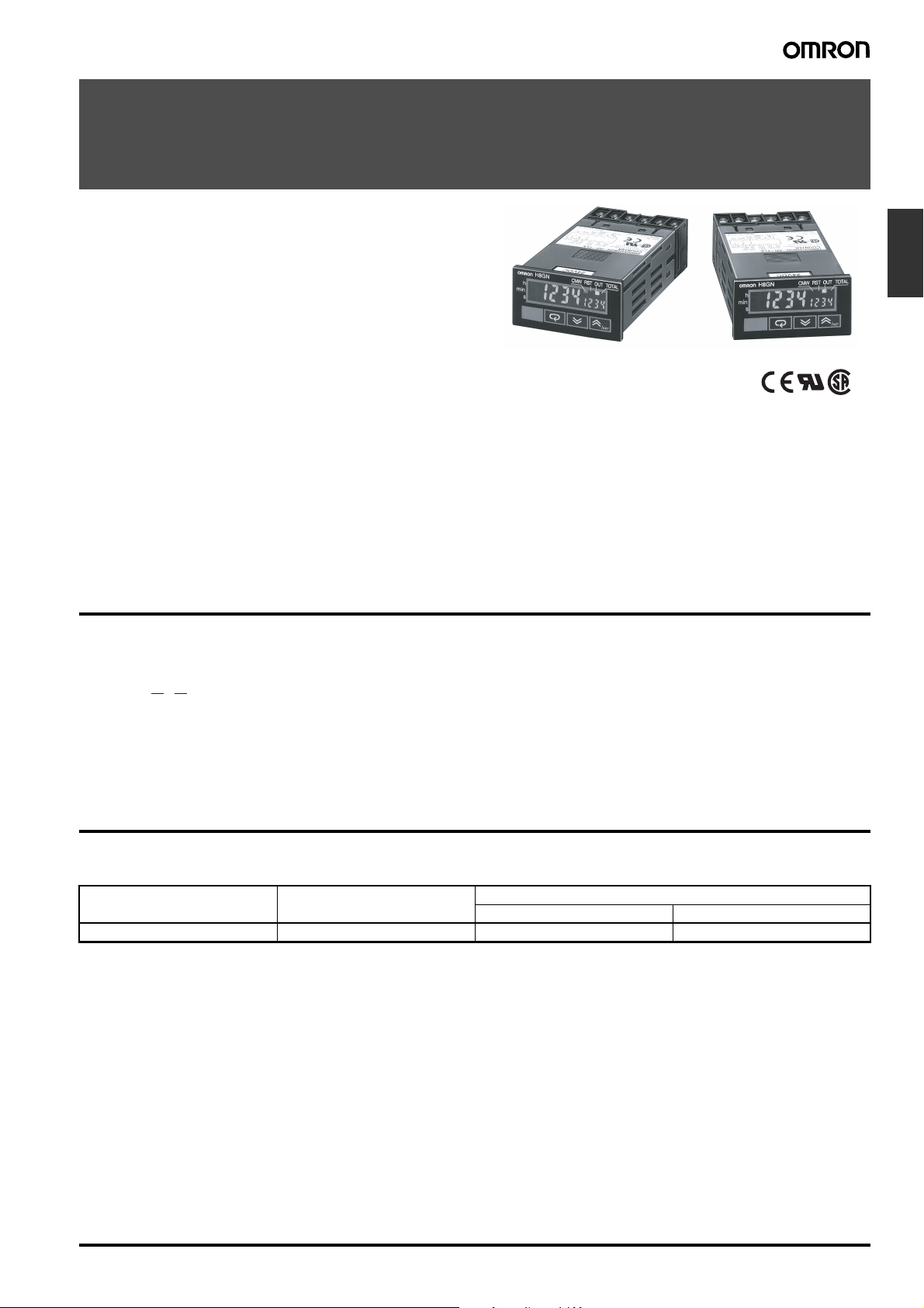
H8GN
World’s Smallest Compact Preset Counter/
Timer
1/32-mm DIN with Communications
• Only 48 x 24 x 83 mm (W x H x D)
• Switch between 4-digit preset counter and 4-digit timer operation.
• While using the preset counter, it is possible to switch the display to monitor the totalizing count value (8 digits).
• Built-in prescaling for counter operation.
• ON/OFF-duty adjustable flicker mode that can be used to perform cyclic control is available for timer operation.
• Four preset values that can be changed by the front panel key
(SV-bank).
• Finger protection terminal block to meet VDE0106/P100.
• Panel surface compatible with NEMA4X/IP66.
• Conforms to UL, CSA, and IEC safety standards as well as CE
Marking.
• Six-language instruction manual provided.
Model Number Structure
■ Model Number Legend
H8GN-AD-@
1 2
1. Supply Voltage
D: 24 VDC
Counters
2. Communications Output Type
None: Communications not supported
FLK: RS-485
Ordering Information
■ List of Models
Supply voltage Output Communications
No communications RS-485
24 VDC Contact output (SPDT) H8GN-AD H8GN-AD-FLK
Preset Counter/Timer H8GN C-59
Specifications
■ Ratings
Rated supply voltage 24 VDC
Operating voltage range 85% to 110% of rated supply voltage
Power consumption 1.5 W max. (for max. DC load) (Inrush current: 15 A max.)
Mounting method Flush mounting
External connections Screw terminals (M3 screws)
Terminal screw tightening torque 0.5 N⋅m max.
Attachment Waterproof packing, flush mounting bracket
Display 7-segment, negative transmissive LCD; time display (h, min, s); CMW, OUT, RST, TOTAL
Present value (red, 7-mm-high characters); Set value (green, 3.4-mm-high characters)
Digits PV: 4 digits
Memory backup EEPROM (non-volatile memory) (number of writes: 100,000 times)
Counter Maximum counting speed 30 Hz or 5 kHz (See note.)
Counting range −999 to 9,999
Input modes Increment, decrement, individual, quadrature inputs
Output modes N, F, C, or K
Timer Time ranges 0.000 to 9.999 s, 0.00 to 99.99 s, 0.0 to 999.9 s, 0 to 9999 s, 0 min 00 s to 99 min 59 s, 0.0 to
Timer modes Elapsed time (Up), remaining time (Down)
Output modes A, B, D, E, F, or Z
Inputs Input signals For Counter: CP1, CP2, and reset
Input method No-voltage input (contact short-circuit and open input)
Start, reset, gate Minimum input signal width: 1 or 20 ms (selectable)
Power reset Minimum power-opening time: 0.5 s
Control output SPDT contact output: 3 A at 250 VAC/30 VDC, resistive load (cos φ = 1)
Minimum applied load 10 mA at 5 VDC (failure level: P, reference value)
Reset system External, manual, and power supply resets (for timer in A, B, D, E, or Z modes)
Sensor waiting time 260 ms max. (Inputs cannot be received during sensor wait time if control outputs are turned OFF.)
Note: The figures given for maximum counting speed are for incrementing or decrementing operation with a prescale value of ×1. If prescaling is
used and 5 kHz is set, the maximum counting speed will be reduced to about half. The maximum counting speed will also be reduced to
about half when the up/down mode is selected.
SV: 4 digits
When total count value is displayed: 8 digits
(Zeros suppressed)
999.9 min, 0 h 00 min to 99 h 59 min, 0.0 h to 999.9 h, 0 h to 9999 h
For Timer: Start, gate, and reset
Short-circuit (ON) impedance: 1 KΩ max. (Approx. 2 mA runoff current at 0 Ω)
Short-circuit (ON) residual voltage:2 VDC max.
Open (OFF) impedance: 100 kΩ min.
Applied voltage: 30 VDC max.
C-60 Preset Counter/Timer H8GN
■ Characteristics
Timer function Accuracy of operating
time and setting error
(including temperature
and voltage effects)
Insulation resistance 100 MΩ min. (at 500 VDC)
Dielectric strength 1,500 VAC, 50/60 Hz for 1 min between output terminals and non-current-carrying metal
Noise immunity Square-wave noise by noise simulator;
Static immunity ± 8 kV (malfunction), ± 15 kV (destruction)
Vibration resistance Malfunction 10 to 55 Hz with 0.35-mm single amplitude each in three directions for 10 min
Destruction 10 to 55 Hz with 0.75-mm single amplitude each in three directions for 2 h
Shock resistance Malfunction
Destruction
Life expectancy Mechanical 10 million operations
Electrical 100,000 operations min. (3 A at 250 VAC, resistive load) (See note.)
Ambient temperature Operating −10°C to 55°C (with no icing or condensation)
Storage −25°C to 65°C (with no icing or condensation)
Ambient humidity 25% to 85%
EMC (EMI): EN61326
Approved standards UL508, CSA C22.2 No.14
Case color Rear section: Gray smoke; Front section: N1.5 (black)
Degree of protection Panel surface: IP66 and NEMA Type 4X (indoors)
Weight Approx. 80 g
Note: Refer to the Life-test Curve.
Signal start: ± 0.03% ± 30 ms max.
Power-ON start: ± 0.03% ± 50 ms max.
parts
510 VAC, 50/60 Hz for 1 min between current-carrying terminals (except output terminals)
and non-current-carrying metal parts
1,500 VAC, 50/60 Hz for 1 min between output terminals and current-carrying terminals (except output terminals)
500 VAC, 50/60 Hz for 1 min between communications terminals and current-carrying terminals (except output terminals)
1,000 VAC, 50/60 Hz for 1 min between contacts not located next to each other
±480 V (between power terminals), ± 600 V (between input terminals)
2
100 m/s
300 m/s
Emission Enclosure: EN55011 Group 1 Class A
(EMS): EN61326
Immunity ESD: EN61000-4-2: 4 kV contact discharge (level 2)
Immunity RF-interference: EN61000-4-3: 10 V/m (Amplitude-modulated,
Immunity Conducted
Disturbance: EN61000-4-6: 3 V (0.15 to 80 MHz) (level 2)
Immunity Burst: EN61000-4-4: 2 kV power-line (level 3);
Immunity Surge: EN61000-4-5: 1 kV between lines
Conforms to EN61010-1/IEC61010-1 (Pollution degree 2/overvoltage category II)
Conforms to VDE0106/P 100 (Finger Protection)
Rear case: IP20
Terminal block: IP20
, 3 times each in six directions
2
, 3 times each in six directions
8 kV air discharge (level 3)
80 MHz to 1 GHz) (level 3);
10 V/m (Pulse-modulated,
900 MHz ± 5 MHz) (level 3)
1 kV I/O signal-line (level 4);
1 kV communications-line (level 3)
(power and output lines) (level 3);
2 kV between grounds
(power and output lines) (level 3)
Counters
Preset Counter/Timer H8GN C-61
■ Communications Specifications
Transmission path connections Multidrop
Communications method RS-485 (two-wire, half duplex)
Synchronization method Start-stop synchronization
Baud rate (See note.) 1,200/2,400/4,800/9,600 bit/s
Transmission code ASCII
Data bit length (See note.) 7 or 8 bits
Stop bit length (See note.) 1 or 2 bits
Error detection (See note.) Vertical parity (none, even, or odd) (See note.)
Block check character (BCC)
Flow control Not supported.
Interface RS-485
Retry function Not supported.
Communications buffer 40 bytes
Reading and writing from H8GN Reading present value and totalizing count value; reading/writing preset and set values; switching be-
tween SV-banks; switching between communications write-enabled/write-prohibited; reading/writing
other initial and advanced function setting parameters
Note: The baud rate, data bit length, stop bit length, and vertical parity can be individually set using the communications setting level.
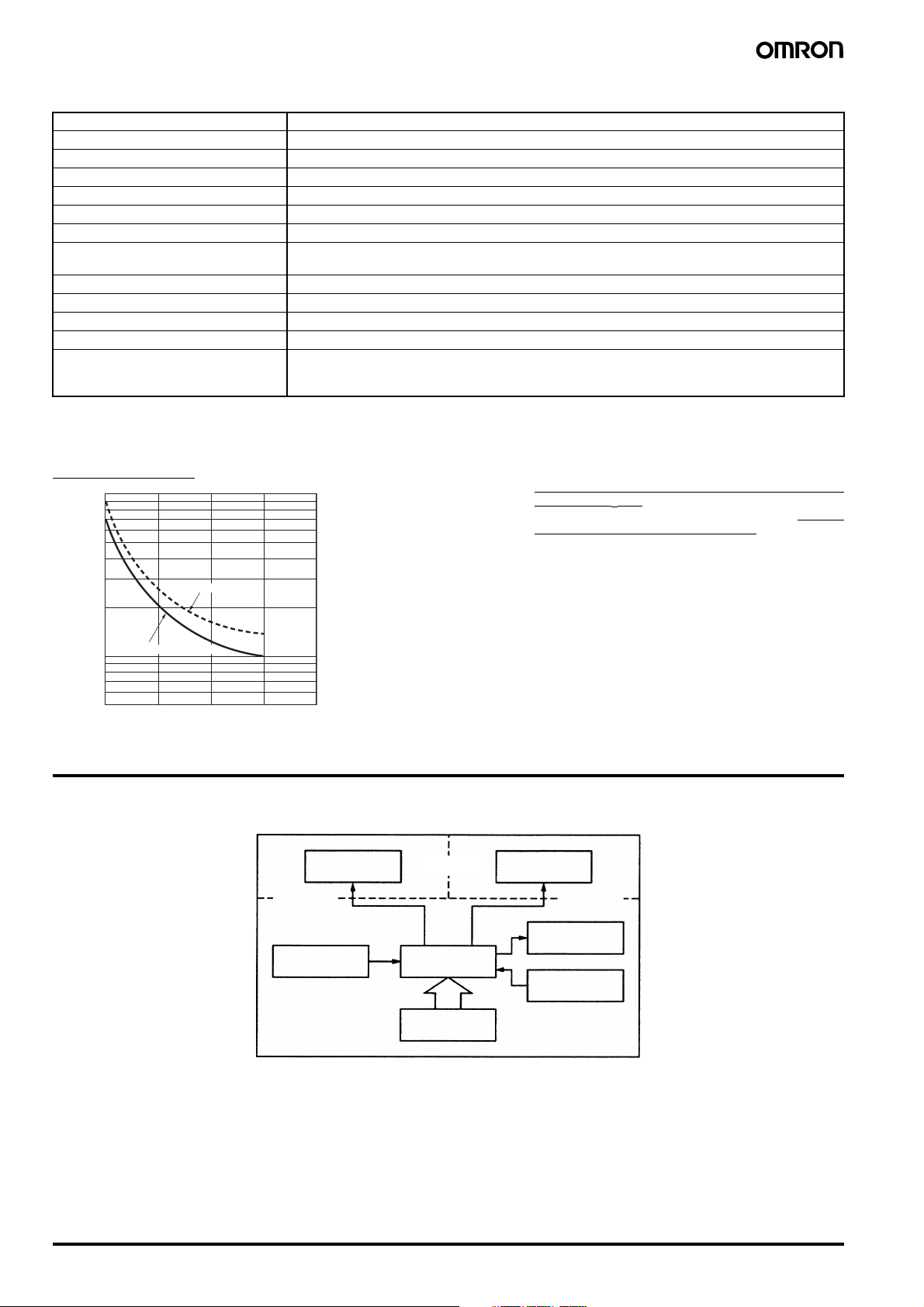
■ Life-test Curve (Reference Values)
Resistive Load
1,000
)
3
700
500
Reference: A maximum current of 0.15 A can be switched at
125 VDC (cosφ = 1) and a maximum current of 0.1 A can
be switched if L/R is 7 ms. In both cases, a life of
100,000 operations can be expected. The minimum
applicable load is 10 mA at 5 VDC (failure level: P).
300
Switching operations (×10
100
250 VAC (cosφ = 1)
70
50
01 2 3
30 VDC (cosφ = 1)
Load current (A)
Connections
■ Block Diagram
4
Communications
circuit
(Functional
insulation)
Input circuit
(Basic
insulation)
Internal
control circuit
Power supply
circuit
Output circuit
Display circuit
Key switch
circuit
(Basic
insulation)
C-62 Preset Counter/Timer H8GN
■ I/O Functions
Inputs Counter inputs CP1/CP2 • Receive count signals.
• Receive increment, decrement, individual, and quadrature inputs.
• In increment mode and decrement mode, CP1 is used for the count input and CP2 is used
for count prohibit input.
Reset • Resets the present value. (Totalizing count value is not reset.)
(In increment mode or increment/decrement mode, the present value returns to 0; in Decrement Mode the present value returns to the set value.)
• The count input is not received during resetting.
• The RST indicator is lit during resetting.
Timer inputs Start • Starts timing.
Reset • Resets the timer. (In elapsed time mode the time returns to 0; in remaining time mode, the
time returns to the set value.)
• During resetting, timing stops and the control output turns OFF.
• The RST indicator is lit during resetting.
Gate • Prohibits timing operation.
Outputs OUT • Output made according to the output mode setting when the set value is reached.
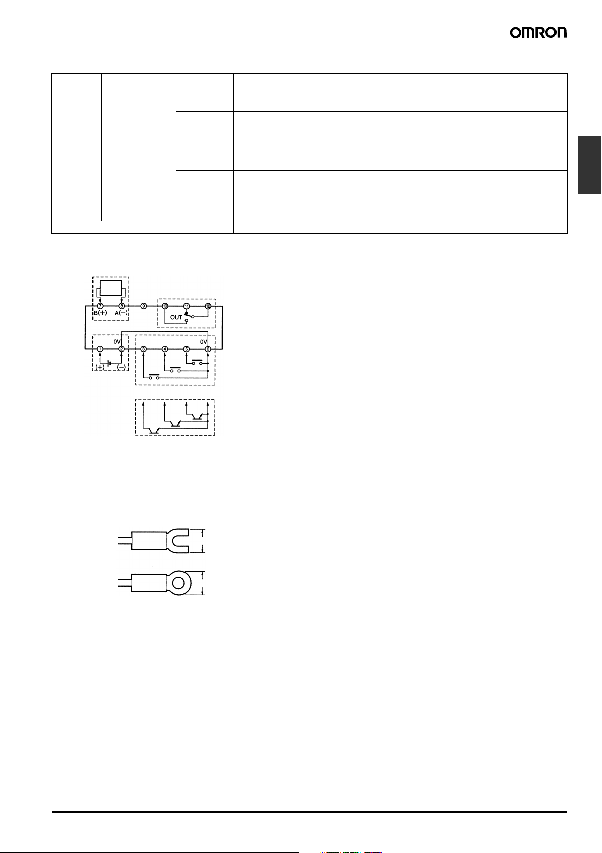
■ Terminal Arrangement
Communications*
RS-485
Not
connected
*Only models with communications
Output
CP1/
CP2/
Gate
Reset
Start
Counters
24-VDC
power supply*
Contact inputs
Open-collector inputs
Note: (2) and (6) are connected internally.
Do not use unused terminals as relay terminals.
Note: *Recommended power supply; eg. OMRON S8VS
■ Wiring
Use the following type of crimp terminals for M3 screw.
5.8 mm max.
5.8 mm max.
Preset Counter/Timer H8GN C-63
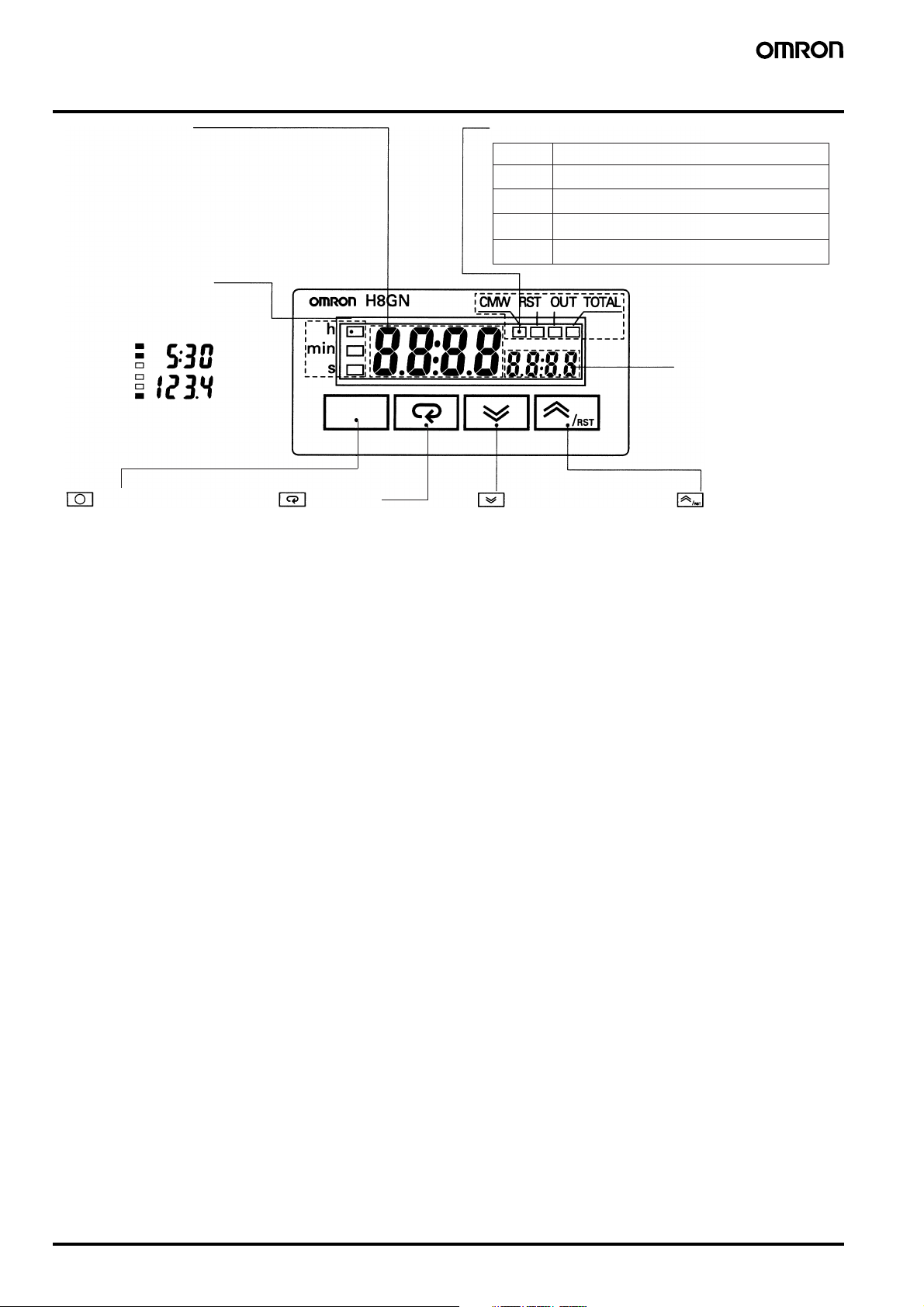
Nomenclature
No. 1 Display
Displays the present value or parameter type.
When totalizing count is displayed, the
leftmost 4 digits of the 8-digit totalizing count
will be displayed. (Zeros suppressed)
Operation display 1
Displays the time unit when the
timer function has been selected.
Example
5 h 30 min
123.4 s
Flashes while timer is on 0.0 min,
0 h 00 min, 0.0 h, or 0 h.
Level Key Mode Key
Press this key to select the setup
level. The setup level is selected in
order "operation level" ←→
"adjustment level", "initial setting
level" ←→ "communications setting
level".
Press this key to select
parameters within each
level.
Operation display 2
Indicator Meaning
CMW
RST
OUT
TOTAL
Each press of this key decreases
values displayed on the No. 2
display. Hold down this key
continuously to decrease values
quickly. Also returns setting
items.
Lit when communications writing is enabled.
Lit during reset using reset input or Reset Key.
Lit when control output is ON.
Lit when totalizing count value is displayed.
Down Key
No. 2 Display
Displays set value or
set value of the
parameter.
Displays the
rightmost 4 digits of
the count value (8
digits) when the
H8GN is used as a
totalizing counter.
(Zeros suppressed)
Up/Reset Key
Each press of this key
increases values
displayed on the No. 2
display. Hold down this
key continuously to
increase values quickly.
Also advances setting
items.
Reset Function
To reset the present
value, press this key
while the present value
is displayed.
If this key is pressed
while the totalizing
count value is
displayed, the totalizing
count value and the
present value will be
reset.
C-64 Preset Counter/Timer H8GN
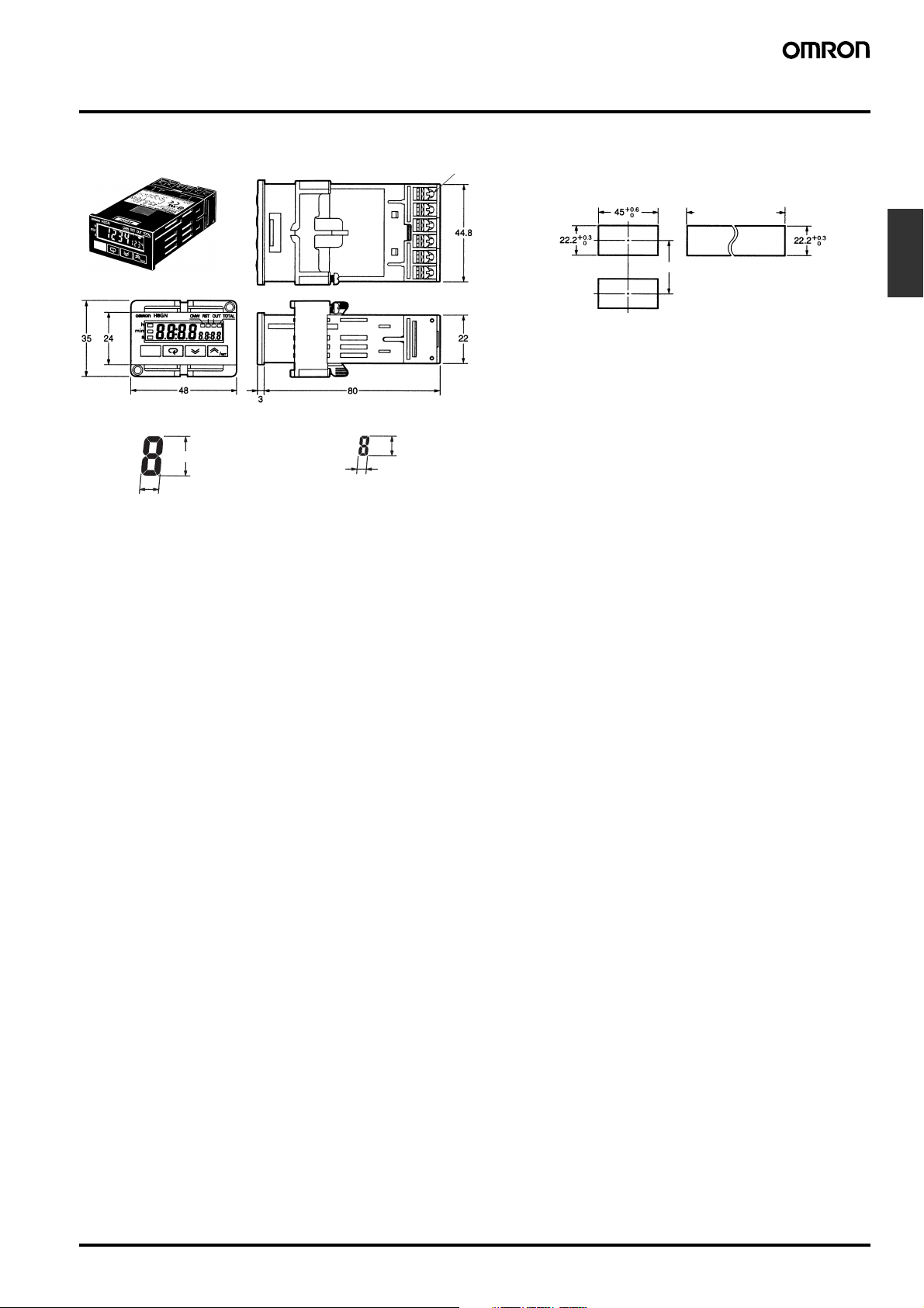
Dimensions
Note: All units are in millimeters unless otherwise indicated.
H8GN
No. 1 display digit size
7 mm
3.3 mm
No. 2 display digit size
3.4 mm
1.6 mm
M3 terminal screw
Panel cutout
Separate
mounting
40 min.
Gang mounting
(48 × No. of units
+1.0
− 2.5)
0
The product cannot
be made waterproof
when gang-mounted.
• Insert the H8GN in the square cutout,
insert the adapter from the back, and
push the H8GN into the cutout as far
as possible. Use screws to secure the
H8GN. To make the H8GN waterproof,
insert waterproof packing and tighten
the screws.
• When mounting two or more products
in a cutout, be sure that the ambient
temperature does not exceed the
specifications.
Counters
Preset Counter/Timer H8GN C-65
Precautions
!Caution
Do not use the product in locations subject to flammable or explosive gases. Doing so may result in explosion.
!Caution
The service life of the output relays depends on the switching capacity and switching conditions. Consider the actual application
conditions and use the product within the rated load and electrical
service life. Using the product beyond its service life may result in
contact deposition or burning.
!Caution
Do not disassemble, repair, or modify the product. Doing so may
result in electric shock, fire, or malfunction.
!Caution
Do not allow metal objects or conductive wires to enter the product. Doing so may result in electric shock, fire, or malfunction.
Other Precautions
• Store at the specified temperature. If the H8GN has been stored at
a temperature of less than −10°C, allow the H8GN to stand at room
temperature for at least 3 hours before use.
• Use the product within the ratings specified for vibration, shock,
submerging in water, and exposure to oil.
• Do not use the product in locations subject to dust, corrosive
gases, or direct sunlight.
• Use the product within the ratings specified for temperature and
humidity.
• The product is designed for 24 VDC. Applying voltages other than
the rated one such as 100 to 240 VAC may damage the internal
elements.
• Separate the input signal devices, input signal cables, and the
product from the source of noise or high-tension cables producing
noise.
• Separate the product from the source of static electricity when
using the product in an environment where a large amount of static
electricity is produced (e.g., forming compounds, powders, or fluid
materials being transported by pipe).
• Do not expose the product to organic solvent such as thinner or
benzine, strong alkali materials, or strong acid materials. Doing so
may damage the product surface.
Application Precautions
1. Do not use the product in locations where condensation may
occur due to high humidity or where temperature changes are
severe.
2. Be sure to wire terminals correctly, with the correct polarity.
3. Maintain the power supply voltage within the allowable ranges.
4. Connect the power supply through a relay or switch so that the
voltage reaches a fixed value immediately. If the voltage
increases gradually the power supply may be reset or outputs
may turn ON.
5. When the power is turned ON, an inrush current (approx. 15 A)
will flow momentarily. Depending on power supply capacities, the
product may not start due to this leakage current. The power supply must be of a sufficiently large capacity.
6. For the main power supply or the power supply for input devices,
use a power supply transformer whose primary side is insulated
from the secondary side and whose secondary side is not
grounded.
7. Leaving the H8GN with outputs ON at a high temperature for a
long time may hasten the degradation of internal parts (such as
electrolytic capacitors). Therefore, use the product in combination
with relays and avoid leaving the product as long as more than 1
month with the output turned ON.
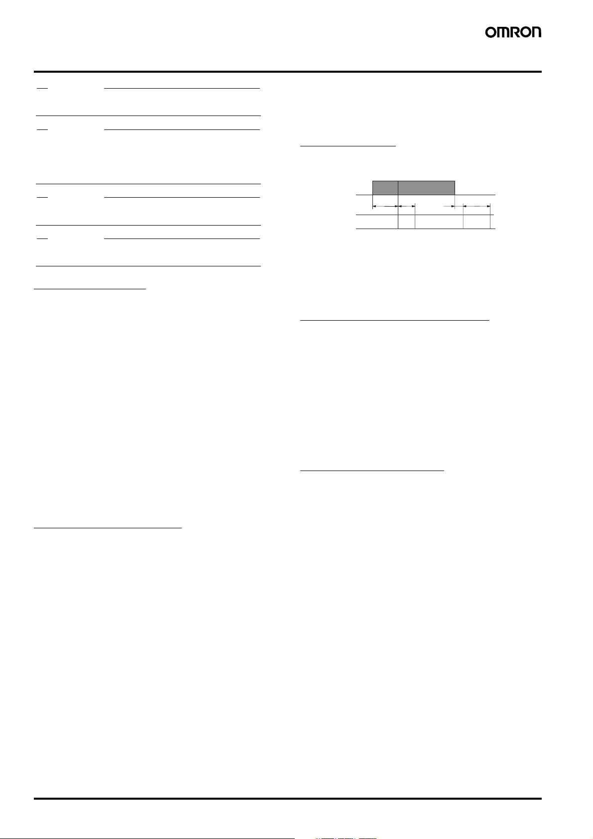
Power Supplies
When turning the power ON and OFF, input signal reception is possible, unstable, or impossible as shown in the diagram below.
Power
ON
supply
OFF
Input Impossible
Turn the power ON and OFF using a relay with a rated capacity of
15 A minimum to prevent contact deterioration due to inrush current
caused by turning the power ON and OFF.
When power is turned ON, a starting current flows momentarily.
Therefore, pay attention to the overcurrent detection level of the
power supply used.
210 ms
0 to 50 ms 0 to 500 ms
5 ms
Possible ImpossibleUnstable
Unstable
Timer Control with Power Start
To allow for the startup time of peripheral devices (sensors, etc.), the
H8GN starts timing operation between 210 to 260 ms after power is
turned ON (see diagram above). For this reason, in operations where
timing starts from power ON, the time display will actually start from
258 ms. If the set value is 258 ms or less, the time until output turns
ON will be a fixed value between 210 and 260. (Normal operation is
possible for set value of 259 ms or more.) In applications where a set
value of 258 ms or less is required, use start timing with signal input.
When the H8GN is used with power start in F mode (i.e., accumulative operation with output on hold), there will be a timer error (approximately 100 ms each time the H8GN is turned ON) due to the
characteristics of the internal circuitry. Use the H8GN with signal
start if timer accuracy is required.
Changing the Set Value
In Counter Operation
When changing the set value during operation, the output will turn
ON if the set value equals the present value.
In Timer Operation
When changing the set value during operation, if the set value is
changed in so that the conditions below are satisfied, the Timer operates in the same way as when the present value reaches the set
value because a constant read-in system is in use. Depending on the
output mode, this may result in output turning ON.
Timer mode UP: Present value ≥ set value
Timer mode DOWN:Elapsed time ≥ set value
Note: When in DOWN mode, the amount set value is changed is add-
ed to or subtracted from the present value.
(Present value = 0)
C-66 Preset Counter/Timer H8GN
 Loading...