

Page 1
)
ls
TEMPERATURE INPUT UNIT
3
0
GT1-TS04T/TS04TCST
GT1-TS04P/TS04PCST
INSTRUCTION MANUAL
Thank you for purchasing this OMRON product.
This manual primarily describes precautions required in installing and
operating the digital controller. Before operating the product, read this
manual thoroughly to acquire sufficient knowledge of the product. Keep
this manual for future reference.
Industrial Automation Company
Tokyo, JAPAN
OMRON Corporation
1615913-6D
To ensure safe and correct use of this product, also read the following
manuals:
• CompoBus/D (Device net) Multiple I/O Terminal Operation Manual(Cat.
No. W348-E1-1)
The above manual can be obtained from any OMRON sales office or
dealer.
NOTICE
Items shown below are necessary for safe usage.
Please note them carefully.
(1) Never disassemble, repair or modify the product.
(2) Do not submit the product to abnormal shock. Doing so might result in
faulty operation.
(3) Do not use the product in the following places:
- Places subject to icing, condensation, dust or corrosive gas (espe-
cially sulfide gas or ammonia gas)
- Places subject to splashing liquid or oil atmosphere
- Place subject to static electricity or other forms of severe noise
(4) Fit the product to a DIN rail correctly.
(5) Separate the communication cables from power lines or high-tension
lines.
(6) Avoid connecting or disconnecting cables with the power ON. Doing so
might result in trouble or faulty operation.
(7) Keep the communication distance within specifications.
(8) Use the appointed communication cables.
(9) Locking Connector Cables
• Before turning the power ON, make sure that the connector cables
are firmly connected.
• Be sure that I/O interface connector is properly locked into place.
(10) Tightening Screws
Tighten screws to the stipulated torque to prevent faulty operation.
Torque: 0.3 to 0.5 N • m
(11) Never execute panel processing and wiring after installation to avoid
any conductive foreign substance inside the product.
Doing so may cause malfunction.
(12) Cleaning
Never use paint thinner or other solvent to clean the product. Doing so
might melt or discolor the surface. Use standard grade alcohol.
(13) Isolate Internal Power Supply that is connected to the product from I/O
Power Supply that is for load.
(14) Be sure to warm up more than 30 minutes before you use.
■ SPECIFICATIONS
● Ratings
Current (I/O unit interface)
Consumption (Internal power supply)
Internal Circuit Power Voltage
Inrush Current
Communication distance I/O unit interface
Ambient Temperature
Ambient Humidity
Storage temperature
Installation
Weight
● Characteristics
Model
Input points
Input Type
Accuracy*1
*2
Conversion Cycle
Temperature Conversion Data
Insulation Resistance
Withstanding Voltage
* 1 Exceptions in accuracy
Input Type and Condition
Input Type K,T in Lower -100°C
Input Type L
Input Type R,S in Lower 200°C
Input Type B in Lower 400°C
* 2 Measurement condition
Accuracy does not include accuracy of external
components (thermocouple, compensating lead wires, etc.)
not included on this unit.
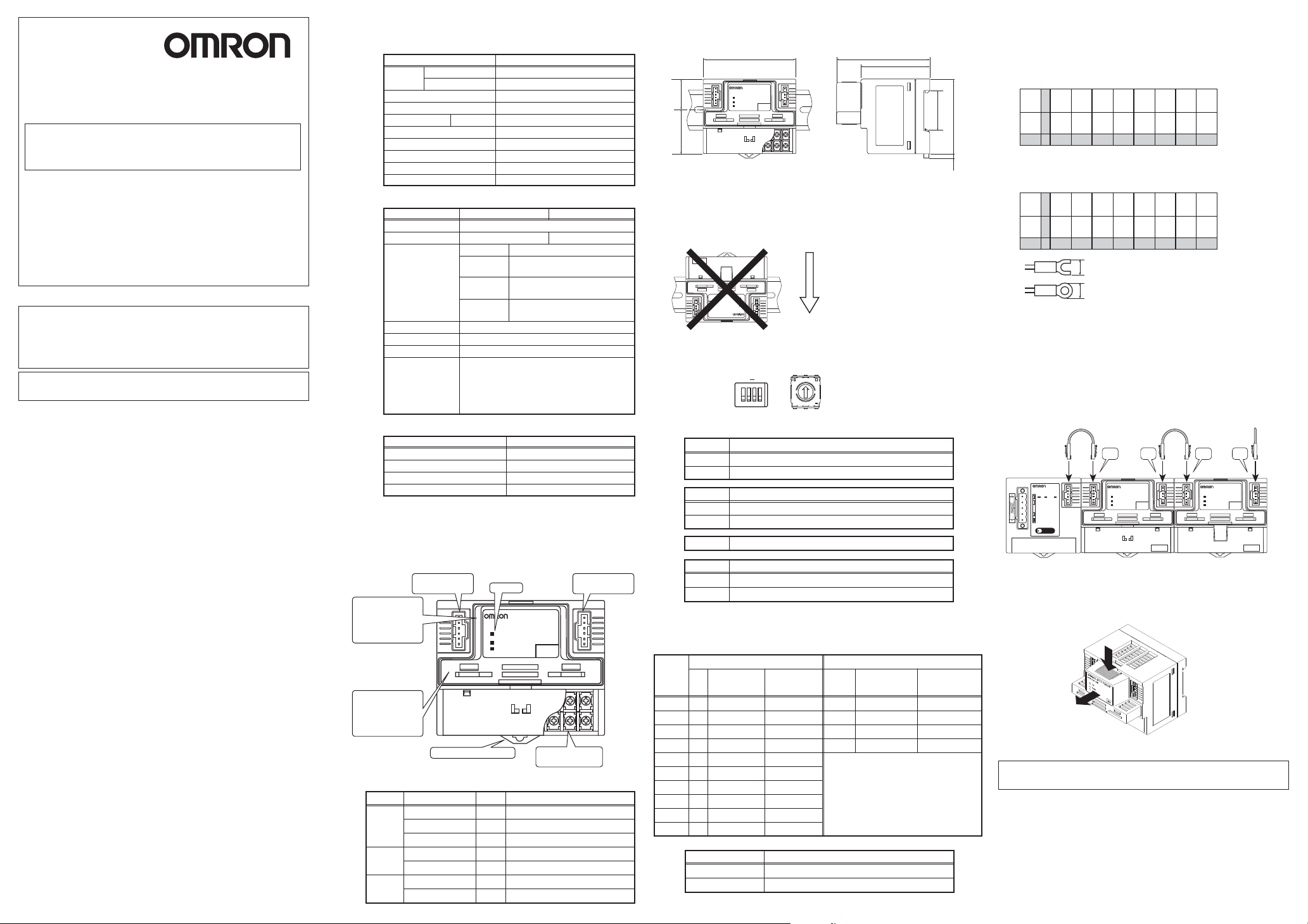
■ NOMENCLATURE
I/O unit interface
Connector
DIP switch
(Side surface where
the cassette is
removed from the
terminal block)
Casset
(The cassette model
names are
GT1-TS04TCST and
GT1-TS04PCST)
■ DISPLAY
The meaning of the each LED is as follows.
LED name
TS
PWR
U.ERR
LED Displaying Color
Green
Red
Green
Red
50mA max.
20.4 to 26.4VDC (24VDC -15 to +10%)
3m in total, 1m max. between each unit
TS04P/T: 210g typ.,TS04PCST/TCST: 90g typ.
TS04T(CST)
R, S, K, J, T, L, B
Input Type
R,S,K,J,T,B
Pt100,JPt100
-200.0 to 650.0°C
Pt100,JPt100
-200.0 to 200.0°C
20MΩ min. (at 250VDC, across insulated circuits
500VAC, 1 minute, Detection Current 1 mA
Across I/O unit interface connector and DIN rail,
Across whole terminals and DIN rail
Across Internal Power Supply and each input
Across I/O unit interface connector and whole termina
Display
ANALOG UNIT
TS
PWR
U.ERR
DIN rail attachment hook
Condition
Lit
Lit
−
Out
Lit
−
Out
Lit
−
Out
80mA max.
10A max., pulse width 1ms max.
-10 to 55°C (no condensation)
25 to 85% (no condensation)
-25 to 65°C
Mounted in a panel
4 points
(±0.3% of indication value or ±1°C,
(±0.3% of indication value or ±0.8°C,
(±0.3% of indication value or ±0.5°C,
Across each input
GT1−TS04P
Accuracy
whichever greater) ±1 digit
whichever greater) ±1 digit
whichever greater) ±1 digit
250ms/4 points
Binary Data
Accuracy
±2°C±1 digit max.
±2°C±1 digit max.
±3°C±1 digit max.
Not defined
IN
Terminal Block
(Under the Cover)
Description
Normal Conditions
I/O unit interface error
Standby (or Not Powered)
Powered
Not Powered
Unit error (or Not Powered)
Device Operational
TS04P(CST)
Pt100, JPt100
I/O unit interface
Connector
879
■ DIMENSIONS (unit : mm)
● GT1-TS04
80
GT1−TS04P
ANALOG UNIT
TS
PWR
U.ERR
IN
37.4 27.6
879
■ DIN Rail Attachment
Be sure to mount on a 35mm DIN rail using the DIN rail attachment hook.
Do not install the product in places to be touched by accident to avoid malfunction caused by static electricity.
Do not block the ventilation holes on the upper side of product to allow heat
to escape.
Be sure to have enough space around the product when installing.
879
TS04T
IN
U.ERR
PWR
TS
ANALOG UNIT
GT1−TS04T
Do not install the TS04T in
vertical direction as shown on
the left. If installed vertically,
the indication accuracy may
not be satisfied.
Vertical direction
■ DIP SWITCH SETTING
DIP Switch
SW1SW
O
N
123
4
4
↑ON
Rotaly DIP Switch
0
1
9
2
8
7
4
6
5
3
● Setting of DIP Switch
Set the unit
SW1
OFF
ON
SW2
OFF
ON
SW3
SW4
OFF
ON
* DIP switch setting is read only when the power is turned ON
*default setting
°C
°F
Set the display mode of temperature data
Normal mode
*default setting
Decimal 2 Columns display mode
Keep OFF
Setting the Setting mode
DIP switch setting enable
*default setting
Remote setting enable
80
60
35
65
4
■ WIRING
● Terminal Arrangement
・GT1-TS04T
SOURCE
Input
0 NC
Input
1 NC
Input
2 NC
Input
879
Input
Input
3 NC
3 NC
3 NC
ANALOG UNIT
TS
PWR
U.ERR
Terminating connector
(attached to the
Communications Unit)
GT1-TS04T
IN
879
A
+24V
+ + + +
SOURCE
Input
0 NC
Input
1 NC
Input
B
- - - -
+0V
2 NC
1 23456789
・GT1-TS04P
SOURCE
Input0 Input0 Input1 Input1 Input2 Input2 Input3 Input
A
+24V
A B A B A B A B
SOURCE
Input
0 NC
Input
1 NC
Input
B
+0V
B B B B
2 NC
1 23456789
6.0mm max.
for M3
6.0mm max.
● Connecting Communications Unit and I/O unit
The product can be connected to a communications unit and other I/O units with a
connecting cable.
・Be sure to disconnect the I/O unit connecting cable after drawing out the cassette.
・Use I/O unit interface (1) when connect to a communication unit.
・Use I/O unit interface (2) when connect to another I/O unit interface (1),
use I/O unit interface (1) when connect to another I/O unit interface (2).
・A terminating connector must be at I/O unit interface (2) of the end unit.
I/O Unit Connecting cable
(attached to I/O Unit)
Communication unit
DRT1-COM
COMMUNICATION UNIT
MS NS TS
No.
■ Installing and drawing out the cassette
Draw out the cassette towards you while pressing its upper side. (See diagram below.)
Do not draw out the cassette while power in ON.
I/O Unit Connecting cable
(attached to I/O Unit)
(1) (1)(2) (2)
GT1-TS04P
ANALOG UNIT
TS
PWR
U.ERR
IN
TS04P TS04T
● Setting of Rotary DIP Switch
Position of
Rotary DIP
Input
Switch
Type
0
1
2
3
4
5
6
7
8
9
GT1-TS04T(CST)
GT1-TS04P(CST)
R
S
K
K
J
J
T
L
L
B
* DIP switch setting is read only when the power is turned ON
GT1-TS04T GT1-TS04P
Range
(°C)
0 to 1700
0 to 1700
-200 to 1300
0.0 to 500.0
-100 to 850
0.0 to 400.0
-200.0 to 400.0
-100 to 850
0.0 to 400.0
100 to 1800
Model
Range
(°F)
0 to 3000
0 to 3000
-300 to 2300
0.0 to 900.0
-100 to 1500
0.0 to 750.0
-300.0 to 700.0
-100 to 1500
0.0 to 750.0
300 to 3200
Default Setting
Input
Type
PT100
-200.0 to 650.0
JPT100
-200.0 to 650.0
PT100
-200.0 to 200.0
JPT100
-200.0 to 200.0
Setting Impossible except above
2
0
Range
(°C)
Range
(°F)
-300.0 to 1200.0
-300.0 to 1200.
-300.0 to 380.0
-300.0 to 380.0
Install the cassette to the right position with much care for direction. Check if the cassette in installed properly by pulling it slightly.
PRECAUTIONS IN USING THE PRODUCT
When the product is used under the circumstances or environment below, ensure
adherence to limitations of the ratings and functions. Also, take countermeasures
for safety precautions such as fail-safe installations.
(1) Use under circumstances or environment which are not described in the
instruction manual.
(2) Use for nuclear power control, railway, aircraft, viecle, incinerator, medical
equipment, entertainment equipment, safety device etc...
(3) Use for applications where death or serious property damage is possible and
extensive safety precautions are required.
Page 2
温度入力ユニット
3
0
0
形 GT1-TS04T/TS04TCST
形 GT1-TS04P/TS04PCST
取扱説明書
オムロン製品をお買いあげいただきありがとうございます。
ご希望どおりの製品かお確かめいただき、この取扱説明書をよく読んで
ご理解の上ご使用ください。
なお、この取扱説明書はお読みになった後も、いつも手元に置いてご使
用ください。
この製品を安全に正しく使用していただくために次のマニュアルを併せ
てご覧ください。
・マルチプル I/O ターミナル マニュアル(Man.No.SBCD-306)
お願い
以下に示す項目は、安全を確保するために必ず守ってください。
(1) この製品を分解したり、修理、改造しないでください。
(2) 製品を落下させたり、異常な振動・衝撃を加えないでください。
故障や誤動作の原因になります。
(3) 次の環境での使用を避けてください。
・直射日光のあたる場所
・腐食性ガスや可燃性ガスのある場所
・塵埃、塩分、鉄粉が多い場所
・水、油、薬品などの飛沫があるところ
・氷結や結露をするようなところ
・静電気や過大なノイズを受けるところ
(4) DIN レールに確実に取付けてください。
(5) 通信ケーブルは動力線、高圧線からは離して設置してください。
(6) 電源を入れた状態でのカセット部、コネクタの着脱は故障や誤動作の
原因となりますので行わないでください。
(7)接続距離については仕様範囲内でご使用ください。
(8)通信線の接続には、指定ケーブルをご使用ください。
正しい使い方
1.接続ケーブルについて
・通電前にコネクタ部が確実に装着されていることを確認してください。
・I/Oユニットインターフェースコネクタ部が確実にロックされている
ことを確認してください。
2.各種ネジの締付けについて
ユニットの各種ネジは誤動作の原因にならないよう、規定のトルクで締付
けてください。
ネジ締めトルク:0.3〜 0.5 N・m
3.盤の加工について
製品を取りつけた後での盤加工、配線処理等はしないでください。
製品内部に導電性異物が侵入し、誤動作の原因になります。
4.清掃について
シンナー類は装着表面を溶かしたり、変色させたりしますので絶対に使用
しないでください。清掃には市販のアルコールを使用してください。
5.電源供給について
本体へ接続する内部電源と他ユニットの負荷駆動用の電源は必ず分離して
ください。誤動作の原因となります。
6.ウォームアップ時間は 30分以上取ってください。
■仕様
●定格
項目
消費電流 (I/O
接続距離 (I/O
ユニットインターフェース
(内部電源)
内部電源電圧
突入電流
ユニットインターフェース
使用周囲温度
使用周囲湿度
保存周囲温度
設置場所
質量
)
20.4〜26.4V DC(24V DC -15%〜+10%
)
TS04T/P: 約210g、TS04T/PCST: 約90g
●性能
温度入力用:形 GT1-TS04T/P(CST)
形式
入力ch数
入力種別
指示精度*1
変換周期
温度変換データ
絶縁抵抗
耐電圧
* 1 指示精度の例外事項
入力種別と条件
K,Tの−100℃以下
L
R,Sの200℃以下
Bの400℃以下
* 2 測定条件
指示精度には、ユニットに含まない外部構成要素
(熱電対、補償導線、その他)の精度は含みません。
TS04T(CST)
R, S, K, J, T, L, B
入力種別
*2
R,S,K,J,T,B
Pt100,JPt100
-200.0〜650.0℃
Pt100,JPt100
-200.0〜200.0℃
I/O
指示値の±0.3%または± 1℃のいずれか大きい方
指示値の±0.3%または± 0.8℃のいずれか大きい方
指示値の±0.3%または± 0.5℃のいずれか大きい方
20MΩ以上(250V DCにおいて、絶 縁されている回 路 間)
500V AC、1分間、検出電流1mA
ユニットインターフェースコ ネクタ
とDINレール間 、端子一括とDINレール間
内部電源端子と各入力端子間、各温度入力端子間
I/Oインタ ーフェースコネクタと端子一括間
±2℃±1ディジット以下
±2℃±1ディジット以下
±3℃±1ディジット以下
仕様
50mA以下
80mA以下
最大10A、パルス幅 1ms以下
総長3m、ユニット間最大 1m
-10〜+55°C(結露のないこと)
25〜85%(結露のないこと)
-25〜+65°C
盤内設置
4ch
精度
±1ディジット
±1ディジット
±1ディジット
250ms/4点
バイナリデータ
精度
規定なし
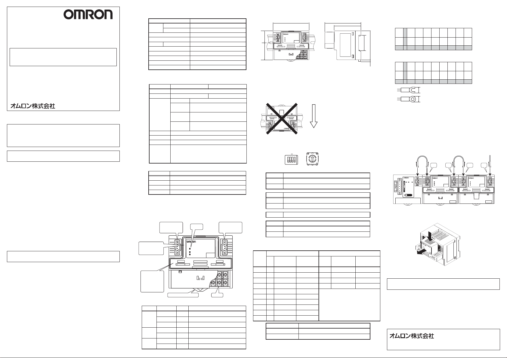
■各部の名称
■表示部
ディップ スイッチ
(カセット部を端子台
から取 り外し た側 面 )
カセット部
(カセット部のみの
型式が
GT1-TS04TCST,
GT1-TS04PCSTと
なります。)
LED表示色
LED名
TS
PWR
U.ERR
I/Oユニット
インターフェース
コネクタ
DINレール取り付けフック
緑
赤
−
緑
−
赤
−
表示部
GT1−TS04P
ANALOG UNIT
TS
PWR
U.ERR
IN
端子台
状態
正常状態
点灯
I/Oユニットインター フェース 異 常
点灯
消灯
イニシャル 中(I/Oユニットインターフェース電源供給なし)
点灯
内部電源供給
消灯
内部電源供給なし
点灯
ユニットが故 障(内部電源供給なし)
消灯
ユニットが正常
表示内容
TS04P(CST)
Pt100, JPt100
I/Oユニット
インターフェース
コネクタ
879
■外形寸法(単位:mm)
● GT1-TS04T/TS04P
)
37.4 27.6
■取り付け
DINレール取り付けフックを使用して DIN35mm のレールに確実に取り付
ANALOG UNIT
TS
PWR
U.ERR
80
GT1−TS04P
IN
879
けてください。
静電気による故障を避けるために偶発的に人が触らない場所に取り付けて
ください。
製品上面の放熱穴をふさがないように隙間をあけて取り付けてください。
879
TS04T
IN
U.ERR
PWR
TS
ANALOG UNIT
GT1−TS04T
TS04Tは左記の方向には取り付
けないでください。
この方向に取り付けると、指示
精度を満足しない場合がありま
す。
鉛直方向
■ディップスイッチ設定
ディップSW
SW1SW
回転ディップ SW
4
0
1
O
N
123
9
2
8
3
7
4
↑ON
6
5
4
●ディップスイッチの設定
表示値の単位切替え
SW1
OFF
ON
SW2
OFF
ON
SW3
SW4
OFF
ON
*工場出荷時設定
°C表示
°F表示
小数点以下2桁表示モード設定
*工場出荷時設定
通常モード
小数点以下2桁表示モード
必ずOFFで使用してください
設定切替え
ディップスイッチによる設定有効
ソフトによる設定有効
※ディップス イッチの設定は通信ユニットの電源投 入時に読み込みます。
●回転ディップスイッチの設定
回転ディップ
スイッチ の
入力
設定
種別
R
0
S
1
K
2
K
3
J
4
J
5
T
6
L
7
L
8
B
9
GT1-TS04T(CST)
GT1-TS04P(CST)
※ディップス イッチの設定は通信ユニットの電源投入時に読み込みます。
GT1-TS04T GT1-TS04P
レンジ
(°C)
0〜1700
0〜1700
-200〜1300
0.0〜500.0
-100〜850
0.0〜400.0
-200.0〜400.0
-100〜850
0.0〜400.0
100〜1800
形式
レンジ
(°F)
0〜3000
0〜3000
-300〜2300
0.0〜900.0
-100〜1500
0.0〜750.0
-300.0〜700.0
-100〜1500
0.0〜750.0
300〜3200
工場出荷時の設定
入力
種別
-200.0〜650.0
Pt100
-200.0〜650.0
JPt100
-200.0〜200.0
Pt100
-200.0〜200.0
JPt100
上記以外には設定しないでください
2
0
80
60
*工場出荷時設定
レンジ
(°C)
35
65
4
レンジ
(°F)
-300.0〜1200.
-300.0〜1200.
-300.0〜380.0
-300.0〜380.0
■配線
●端子配列
・形 GT1-TS04Tの場合
SOURCE
入力0 NC 入力1 NC 入力2 NC 入力3 NC
A
+24V
+ + + +
SOURCE
入力0 NC 入力1 NC 入力2 NC 入力3 NC
B
- - - -
+0V
1 23456 789
・形 GT1-TS04Pの場合
SOURCE
入力0 入力0 入力1 入力1 入力2 入力2 入力3 入力
A
+24V
A B A B A B A B
SOURCE
入力0 NC 入力1 NC 入力2 NC 入力3 NC
B
+0V
B B B B
1 23456 789
6.0mm以下
6.0mm以下
M3用
●通信ユニットや他の I/ O ユニットとの接続
I/ Oユニット接続ケーブルを使用して、通信ユニットや他のI / O ユニットと接続し
ます。
・I/ Oユニット接続ケーブルをはずす際にはカセット部を取り外した状態で行ってく
ださい。
・通信ユニットと接続するときには、(1)側を接続してください。
・他の I/ Oユニットと接続するときには、(2)側は他のユニットの(1)側、(1)側は他の
I/ O ユニットの(2)側と接続してください。
・最終端の I / O ユニットの(2)側には、必ずエンドコネクタを接続してください。
■カセット部の取外し
カセット部を取り外すには、カセットの上部を押したまま手前に引き抜きます。(下図
参照) 通電中はカセットの取り外しをしないでください。
カセット部を取り付けるには、向きに気をつけながらカセット部を奥まで押込んでくだ
さい。奥まで押込んだら軽く引いて抜けないことを確認してください。
通信ユニット
I/Oユニット接続ケーブル
(I/Oユニット付属)
DRT1-COM
COMMUNICATION UNIT
MS NS TS
No.
I/Oユニット接続ケーブル
(I/Oユニット付属)
(1) (1)(2) (2)
GT1-TS04P
ANALOG UNIT
TS
PWR
U.ERR
IN
TS04P TS04T
879
エンドコネクタ
(通信ユニット付属)
GT1-TS04T
ANALOG UNIT
TS
PWR
U.ERR
ご使用に際してのお願い
次に示す条件や環境で使用する場合は、定格、機能に対して余裕を持った
使い方やフェールセーフなどの安全対策へのご配慮をいただくとともに、
当社営業担当者までご相談くださるようお願いいたします。
1.取扱説明書に記載のない条件や環境での使用
2.原子力制御・鉄道・航空・車両・燃焼装置・医療機器・娯楽機械・安全
機器などへの使用
3.人命や財産に大きな影響が予測され、特に安全性が要求される用途への
使用
インダストリアルオートメーションビジネスカンパニー
IN
879
 Loading...