

Page 1

Cat. No. W476-E1-01
SmartSlice
GRT1-CRT
CompoNet Communications Unit
OPERATION MANUAL
Page 2

SmartSlice GRT1-CRT CompoNet Communications Unit
Operation Manual
Produced May 2008
Page 3

iv
Page 4

Introduction
Thank you for buying a SmartSlice CompoNet Communications Unit.
The CompoNet Communications Unit is an interface unit which complies with the CompoNet
standard. It connects SmartSlice I/O Units to a CompoNet Master Unit.
Be sure you understand the functions and performance of the Units fully before you use them.
Intended Audience
This manual is for the personnel below. This personnel must understand electrical systems (must
be an electrical engineer or the equivalent).
Personnel responsible for the selection of FA systems
Personnel responsible for the designs of FA systems
Personnel responsible for the installation of and connections in FA systems
Personnel responsible for the management of FA systems
Precaution
Introduction
This manual contains data which is necessary for you to use a CompoNet Communications Unit.
Read and understand this manual fully before you use the CompoNet Communications Unit. After
you read this manual, keep it in a safe location where it will be available for use when necessary.
Be sure that the end user of the CompoNet Communications Unit has this manual.
v
Page 5

Read and Understand this Manual
Read and Understand this Manual
Please read and understand this manual before using the product. Please consult your OMRON
representative if you have any questions or comments.
Warranty and Limitations of Liability
WARRANTY
OMRON's exclusive warranty is that the products are free from defects in materials and workmanship
for a period of one year (or other period if specified) from date of sale by OMRON.
OMRON MAKES NO WARRANTY OR REPRESENTATION, EXPRESS OR IMPLIED, REGARDING
NON-INFRINGEMENT, MERCHANTABILITY, OR FITNESS FOR PARTICULAR PURPOSE OF THE
PRODUCTS. ANY BUYER OR USER ACKNOWLEDGES THAT THE BUYER OR USER ALONE HAS
DETERMINED THAT THE PRODUCTS WILL SUITABLY MEET THE REQUIREMENTS OF THEIR
INTENDED USE. OMRON DISCLAIMS ALL OTHER WARRANTIES, EXPRESS OR IMPLIED.
LIMITATIONS OF LIABILITY
OMRON SHALL NOT BE RESPONSIBLE FOR SPECIAL, INDIRECT, OR CONSEQUENTIAL
DAMAGES, LOSS OF PROFITS OR COMMERCIAL LOSS IN ANY WAY CONNECTED WITH THE
PRODUCTS, WHETHER SUCH CLAIM IS BASED ON CONTRACT, WARRANTY, NEGLIGENCE, OR
STRICT LIABILITY.
In no event shall the responsibility of OMRON for any act exceed the individual price of the product on
which liability is asserted.
IN NO EVENT SHALL OMRON BE RESPONSIBLE FOR WARRANTY, REPAIR, OR OTHER CLAIMS
REGARDING THE PRODUCTS UNLESS OMRON'S ANALYSIS CONFIRMS THAT THE PRODUCTS
WERE PROPERLY HANDLED, STORED, INSTALLED, AND MAINTAINED AND NOT SUBJECT TO
CONTAMINATION, ABUSE, MISUSE, OR INAPPROPRIATE MODIFICATION OR REPAIR.
vi
Page 6

Read and Understand this Manual
Application Considerations
SUITABILITY FOR USE
OMRON shall not be responsible for conformity with any standards, codes, or regulations that apply to
the combination of products in the customer's application or use of the products.
At the customer's request, OMRON will provide applicable third party certification documents identifying
ratings and limitations of use that apply to the products. This information by itself is not sufficient for a
complete determination of the suitability of the products in combination with the end product, machine,
system, or other application or use.
The following are some examples of applications for which particular attention must be given. This is not
intended to be an exhaustive list of all possible uses of the products, nor is it intended to imply that the
uses listed may be suitable for the products:
• Outdoor use, uses involving potential chemical contamination or electrical interference, or conditions
or uses not described in this manual.
• Nuclear energy control systems, combustion systems, railroad systems, aviation systems, medical
equipment, amusement machines, vehicles, safety equipment, and installations subject to separate
industry or government regulations.
• Systems, machines, and equipment that could present a risk to life or property.
Please know and observe all prohibitions of use applicable to the products.
NEVER USE THE PRODUCTS FOR AN APPLICATION INVOLVING SERIOUS RISK TO LIFE OR
PROPERTY WITHOUT ENSURING THAT THE SYSTEM AS A WHOLE HAS BEEN DESIGNED TO
ADDRESS THE RISKS, AND THAT THE OMRON PRODUCTS ARE PROPERLY RATED AND
INSTALLED FOR THE INTENDED USE WITHIN THE OVERALL EQUIPMENT OR SYSTEM.
vii
Page 7

Read and Understand this Manual
Disclaimers
CHANGE IN SPECIFICATIONS
Product specifications and accessories may be changed at any time based on improvements and other
reasons.
It is our practice to change model numbers when published ratings or features are changed, or when
significant construction changes are made. However, some specifications of the products may be
changed without any notice. When in doubt, special model numbers may be assigned to fix or establish
key specifications for your application on your request. Please consult with your OMRON representative
at any time to confirm actual specifications of purchased products.
DIMENSIONS AND WEIGHTS
Dimensions and weights are nominal and are not to be used for manufacturing purposes, even when
tolerances are shown.
PERFORMANCE DATA
Performance data given in this manual is provided as a guide for the user in determining suitability and
does not constitute a warranty. It may represent the result of OMRON's test conditions, and the users
must correlate it to actual application requirements. Actual performance is subject to the OMRON
Warranty and Limitations of Liability.
ERRORS AND OMISSIONS
The information in this manual has been carefully checked and is believed to be accurate; however, no
responsibility is assumed for clerical, typographical, or proofreading errors, or omissions.
viii
Page 8
Safety Precautions
Safety Indications
The indications below are used in this manual for safety precautions which are necessary to use the
CompoNet Communications Unit safely. The contents of these safety precautions are important. Always obey them.
These are the indications for safety precautions.
Indicates a potentially hazardous situation which, if not
WARNING
Caution
avoided, could result in death or serious injury.
Additionally, there may be severe property damage.
Indicates a potentially hazardous situation which, if not
avoided, may result in minor or moderate injury, or property
damage.
Safety Precautions
Precaution for
Safe Usage
Precaution for
Correct Usage
• “Precautions for Safe Application” shows the operations that you must do or
not do to use the product safely.
• “Precautions for Correct Application” shows operations that you must do or not
do to make sure that the product operates, prevent malfunctions, and prevent
bad effects on performance and functions.
ix
Page 9
Safety Precautions
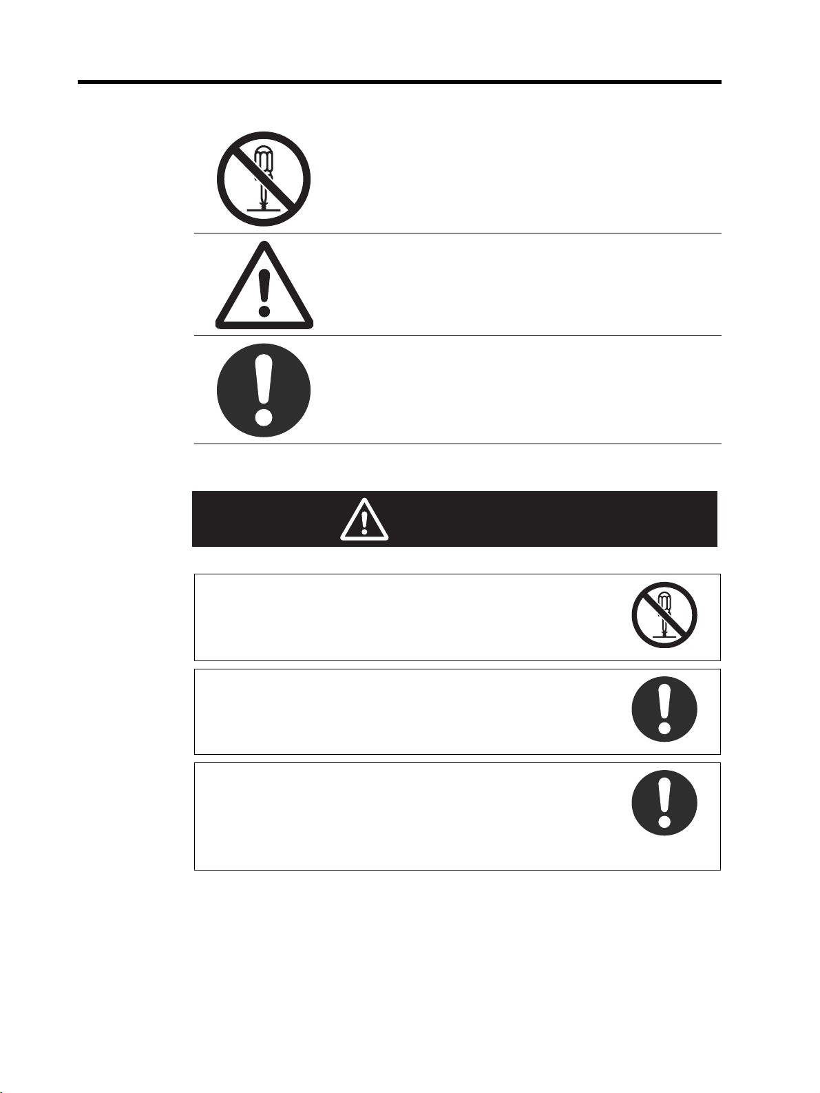
Descriptions of Symbols
This symbol shows operations that you must not do.
The specified operation shows in the circle.
This example shows “do not disassemble.”
This symbol shows precautions (including warnings).
The specified operation shows in the triangle.
This example shows a general precaution.
This symbol shows operations that you must do.
The specified operation shows in the circle.
This example shows a general precaution for something that
you must do.
WARNING
Do not try to disassemble a Unit or touch the terminal block while
the power is ON. Doing this can cause electrical shock.
Make sure that the voltage and current input to the Units are in the
specified ranges. If the voltage and current are not in the specified
ranges, there can be Unit malfunctions or fire.
Turn OFF the I/O power supply to a SmartSlice I/O Unit before you
replace it with the online replacement procedure. If there is external
power to a terminal for a Relay Output Slave, for example, turn OFF
the external power before you replace the SmartSlice I/O Unit. If
you replace a Slave I/O Unit with the power ON, incorrect outputs,
incorrect inputs, or electric shock can occur.
x
Page 10
Safety Precautions
Apply safety measures in external circuits (that is, not in the SmartSlice I/O Terminal) to keep safety in the system. These measures
must keep safety if a malfunction in the control system or other external factor which has an effect on the control system causes a
problem. Include the items below. Not doing this can cause serious
accidents.
• There must be emergency stop circuits, interlock circuits, limit circuits, and other safety measures in external control circuits.
• The SmartSlice outputs can stay ON or OFF because of welding
or burning of the output relays, or destruction of the output transistors. As a countermeasure for such errors, there must be external safety measures to keep safety in the system.
• The SmartSlice I/O Terminal will continue operating when one or
more I/O Units are missing from the SmartSlice I/O Terminal. The
other I/O Units will continue the control operations, including the
control of the outputs. As a countermeasure for such errors, there
must be external safety measures to keep safety in the system.
The CPU Unit refreshes I/O when the program is stopped in PROGRAM mode. Fully make sure that it is safe before changing the
status of bits or words in memory allocated to Output Slaves, Special I/O Units, or CPU Bus Units. If you change the bits or words allocated to a Slave or Unit, you could cause incorrect operation of
the loads connected to the Slave or Unit. The operations below will
change memory status.
• Transferring I/O memory data to the CPU Unit from a Programming Device
• Changing present values in memory from a Programming Device
• Force-setting or force-resetting bits from a Programming Device
• Transferring I/O memory files from a Memory Card or EM file
memory to the CPU Unit
• Transferring I/O memory from a host computer or from a PLC on
a network
xi
Page 11

Precautions for Safe Usage
Precautions for Safe Usage
• Put a Unit in the special box during transportation. Make sure that the Unit is moved carefully, and
not given too much vibration or shock during transportation.
• Do not let a Unit fall or give it too much vibration or shock. This can cause malfunction or cause
damage to the Unit.
• Install the SmartSlice I/O Terminal correctly on DIN Track.
• Be sure that you correctly lock the terminal block, the communications cable connectors, and other
items with locking devices.
• Correctly connect the Units as this manual shows.
• Interference between the Flat Cables for more than one CompoNet System can cause operation
that is not stable. Keep the Flat Cables for different CompoNet Systems apart by a minimum of
5 mm. Interference can occur for Sheathed Cable or Unsheathed Cable.
• Do not let metal objects enter the Unit when connecting or installing it.
• Connect ferrules to the wires when you connect the wires. Do not connect stranded wires directly
to terminals.
• Use the specified communications cables and connectors.
• Use the correct polarity when connecting the terminals.
• Put the ferrules fully into the holes.
• Do a full check of the terminal block before you attach it.
• Do not bend the cables to more than their normal bending radius or pull on the cables.
• Obey the following precautions when connecting communications cables.
• Keep the communications cables away from the power lines or high-tension lines.
• Do not bend the communications cables with too much force.
• Do not pull on the communications cables with too much force.
• Do not put objects on the communications cables.
• Put the communications cables in ducts.
• If the power supply conditions are bad, install countermeasures to make sure that the power
supply always has the rated voltage.
• You must make interlock circuits, limit circuits, and other safety measures in circuits that are
external to the control system.
• Use the power supply voltage which this manual specifies.
• Make sure that there will be no problems when the Unit changes to fixed allocations for the I/O
Areas before you clear the Registration Table. (You set user remote I/O allocations in the
Registration Table.)
• Do not let the communications distance be higher than the specified value.
• Install circuit breakers and other safety measures to prevent Unit damage which short-circuits in
external wires can cause.
• Install failsafe measures to make sure that the system is safe if disconnected signal lines or short
power interruptions cause incorrect signals.
• Always obey the voltage specifications for power supply connections and I/O jumpers. Incorrect
connections can cause malfunctions.
• Do not apply a voltage or connect a load which is larger than the maximum switch capacity to an
Output Slave.
• Do not apply a voltage which is larger than the rated voltage to an Input Slave.
• Be sure there are no mistakes in connections or switch settings before you turn ON the power
supply.
xii
Page 12

Precautions for Safe Usage
• Be sure to turn OFF the power to the PLC and Slaves before doing these operations.
• Assembling a SmartSlice I/O Terminal
• Setting the rotary switches
• Connecting cables
• Be sure that there will be no bad effects on the system before doing these operations.
• Changing the operating mode of the CPU Unit
• Setting or resetting bits in memory
• Changing set values or present values on the user program
• Before touching a Unit, touch a grounded metal object to release static electricity from your body.
• When you replace a part, be sure that the specifications of the replacement part are correct.
• Do not try to disassemble, repair, or change a Unit.
xiii
Page 13

Precautions for Correct Usage
Precautions for Correct Usage
Correctly install the Units as this manual shows.
Do not install the Units in these locations.
• Locations with direct sunlight
• Locations with temperatures or humidity not in the range specified in the specifications
• Locations with condensation as the result of large changes in temperature
• Locations with corrosive gases or flammable gases
• Locations with dust (specially iron dust) or salts
• Locations with water, acid, oil, or chemicals
• Locations with shock or vibration
Install applicable and sufficient countermeasures if you install the system in these locations.
• Locations with static electricity or other types of noise
• Locations with strong electromagnetic fields
• Locations with possible exposure to radioactivity
• Locations near power lines
xiv
Page 14

EC Directives
Applicable Directives
•EMC Directive
• Low Voltage Directive
Concepts
EMC Directive
The SmartSlice I/O Terminals are electrical devices which are installed in a machine in application.
The Terminals comply with the EMC Directive. This makes it easier for the machine in which a Terminal is installed to more easily comply with the EMC directive. (See note.)
The EMC-related performance of the OMRON devices which comply with EC Directives changes
with the machine in which they are installed. This includes the configuration, connections, and other
conditions of the machine. The customer must do the checks to make sure that the devices and the
machine conform to EMC standards.
Note:
The applicable EMC (electro-magnetic compatibility) standards are EN 61131-2 and EN 61000-6-2
for EMS (electro-magnetic susceptibility) and EN 61131-2 and EN 61000-6-4 for electro-magnetic
interference. The 10-m regulations apply for radiated emissions.
EC Directives
Low Voltage Directive
Devices which operate at voltages from 50 to 1,000 VAC or 75 to 1,500 VDC must comply with the
related safety requirements. The applicable standard is EN 61131-2.
Complying with EC Directives
The SmartSlice I/O Units comply with EC Directives. These measures are necessary for the machine containing a SmartSlice I/O Units to comply with the EC Directives.
1. You must install the SmartSlice I/O Units in a control panel.
2. You must use reinforced insulation or double insulation for the DC power supplies used for the
Unit power supplies, and the I/O power supplies. Make sure that the outputs are stable if a 10-ms
interruption occurs at the input.
We recommend the S82J Power Supply which is made by OMRON. (See note.)
3. The SmartSlice I/O Units which conform to EC Directives conform to the EMI standards (EN
61131-2 (Immunity Zone A), EN 61000-6-2, and EN 61000-6-4). The radiated emission properties (10-m regulations) can change with the configuration of the control panel, other devices
which are connected to the control panel, connections, and other conditions.
You must make sure that the completed machine complies with EC Directives.
4. Compliance tests were done with I/O wires of a maximum length of 30 m.
Note:
Compliance tests for EMC standards were done with the recommended power supply.
xv
Page 15

Related Manuals
Related Manuals
This table shows the manuals which are related to the CompoNet Communications Unit. Read
these manuals together with this Manual.
Cat. No. Manual Contents
W476 (this
manual)
W455
W456
W342
SmartSlice CompoNet
Communications Unit
Operation Manual
GRT1 Series SmartSlice
I/O Units Operation Manual
CS/CJ Series CompoNet
Master Unit Operation
Manual
SYSMAC CS/CJ/CP Series and SYSMAC One
NSJ Series Communications Commands Reference Manual
This manual tells you about the functions, specifications, and
operating procedures of the CompoNet Communications
Unit.
This manual tells you about the models, functions, specifications, and operating procedures of the SmartSlice I/O Units.
This manuals tells you about the CompoNet network, communications specifications, connection procedures, and the CS/
CJ-series CompoNet Master Unit.
This manual tells you about the communications commands
which you can use with the CS/CJ-series CompoNet Master
Unit.
xvi
Page 16

About this Manual
Section Overview
Section 1 tells you about the SmartSlice system. It also tells you
about the features, system configuration, and specifications of the
CompoNet Communications Unit.
Section 2 tells you about the names and functions of the parts of the
CompoNet Communications Unit.
Section 1
Section 2
Features and System
Configuration
Nomenclature and
Functions
About this Manual
Section 3 Installing the Units
Section 4 Connecting the Units
Section 5
Section 6 Smart Functions
Section 7 Basic Operation
Section 8
Section 9 Error Procedures
Appendices
Unit Settings and I/O
Allocations
Remote I/O Communications
Section 3 tells you how to install the CompoNet Communications
Unit and SmartSlice I/O Units.
Section 4 tells you how to connect the CompoNet Communications
Unit and SmartSlice I/O Units.
Section 5 tells you how to set the unit address and unit number. It
also tells how to allocate I/O in the CompoNet Master Unit.
Section 6 tells you about the many smart functions of the SmartSlice
system.
Section 7 gives the procedures for and example of operating a
SmartSlice system.
Section 8 tells you about the communications timing for remote I/O
communications and message communications. It also gives more
information on communications.
Section 9 tells you how to troubleshoot problems that you can have
with the CompoNet Communications Unit and SmartSlice I/O Units.
It also tells how to see the error history with the CX-Integrator.
The appendices give an overview of explicit messages (for example,
to send commands) and a list of command functions. The appendices also give lists of related products.
xvii
Page 17

About this Manual
xviii
Page 18

TABLE OF CONTENTS
SECTION 1
Features and System Configuration . . . . . . . . . . . . . . . . . . . 1
1-1 The SmartSlice I/O System . . . . . . . . . . . . . . . . . . . . . . . . . . . . . . . . . . . . . . . . . . . . . . . . . . 2
1-2 Features of the CompoNet SmartSlice I/O Terminals . . . . . . . . . . . . . . . . . . . . . . . . . . . . . . 3
1-3 System Configuration . . . . . . . . . . . . . . . . . . . . . . . . . . . . . . . . . . . . . . . . . . . . . . . . . . . . . . 5
1-4 Specifications. . . . . . . . . . . . . . . . . . . . . . . . . . . . . . . . . . . . . . . . . . . . . . . . . . . . . . . . . . . . . 7
SECTION 2
Nomenclature and Functions . . . . . . . . . . . . . . . . . . . . . . . . . 11
2-1 Nomenclature. . . . . . . . . . . . . . . . . . . . . . . . . . . . . . . . . . . . . . . . . . . . . . . . . . . . . . . . . . . . . 12
2-2 Indicators . . . . . . . . . . . . . . . . . . . . . . . . . . . . . . . . . . . . . . . . . . . . . . . . . . . . . . . . . . . . . . . . 14
2-3 Switches. . . . . . . . . . . . . . . . . . . . . . . . . . . . . . . . . . . . . . . . . . . . . . . . . . . . . . . . . . . . . . . . . 18
SECTION 3
Installing the Units . . . . . . . . . . . . . . . . . . . . . . . . . . . . . . . . . 21
3-1 Installing a SmartSlice I/O Terminal . . . . . . . . . . . . . . . . . . . . . . . . . . . . . . . . . . . . . . . . . . . 22
3-2 Installing the Turnback Units . . . . . . . . . . . . . . . . . . . . . . . . . . . . . . . . . . . . . . . . . . . . . . . .27
SECTION 4
Connecting the Units . . . . . . . . . . . . . . . . . . . . . . . . . . . . . . . 29
4-1 Connecting the Communications Cables. . . . . . . . . . . . . . . . . . . . . . . . . . . . . . . . . . . . . . . . 30
4-2 Connecting the Power Supply Cables . . . . . . . . . . . . . . . . . . . . . . . . . . . . . . . . . . . . . . . . . . 31
4-3 Connecting the Turnback Cables. . . . . . . . . . . . . . . . . . . . . . . . . . . . . . . . . . . . . . . . . . . . . . 35
4-4 Precautions When Connecting the Power Supplies. . . . . . . . . . . . . . . . . . . . . . . . . . . . . . . . 36
4-5 Connecting the Signal Lines for External Devices . . . . . . . . . . . . . . . . . . . . . . . . . . . . . . . . 38
SECTION 5
Unit Settings and I/O Allocations . . . . . . . . . . . . . . . . . . . . . 39
5-1 Setting the Node Addresses. . . . . . . . . . . . . . . . . . . . . . . . . . . . . . . . . . . . . . . . . . . . . . . . . .40
5-2 Unit Numbers for SmartSlice I/O Units . . . . . . . . . . . . . . . . . . . . . . . . . . . . . . . . . . . . . . . . 41
5-3 I/O Allocations to CompoNet Master Unit . . . . . . . . . . . . . . . . . . . . . . . . . . . . . . . . . . . . . . 42
SECTION 6
Smart Functions . . . . . . . . . . . . . . . . . . . . . . . . . . . . . . . . . . . 53
6-1 Overview of Smart Functions . . . . . . . . . . . . . . . . . . . . . . . . . . . . . . . . . . . . . . . . . . . . . . . . 54
6-2 Registration Table . . . . . . . . . . . . . . . . . . . . . . . . . . . . . . . . . . . . . . . . . . . . . . . . . . . . . . . . . 54
6-3 Backup Function . . . . . . . . . . . . . . . . . . . . . . . . . . . . . . . . . . . . . . . . . . . . . . . . . . . . . . . . . . 57
6-4 Automatic Restore Function . . . . . . . . . . . . . . . . . . . . . . . . . . . . . . . . . . . . . . . . . . . . . . . . . 58
6-5 Replacing Units Online . . . . . . . . . . . . . . . . . . . . . . . . . . . . . . . . . . . . . . . . . . . . . . . . . . . . . 59
6-6 Automatic Baud Rate Recognition . . . . . . . . . . . . . . . . . . . . . . . . . . . . . . . . . . . . . . . . . . . . 59
6-7 Software Setting of I/O Allocations . . . . . . . . . . . . . . . . . . . . . . . . . . . . . . . . . . . . . . . . . . . 60
xix
Page 19

TABLE OF CONTENTS
6-8 Unit Conduction Time Monitor . . . . . . . . . . . . . . . . . . . . . . . . . . . . . . . . . . . . . . . . . . . . . . . 71
6-9 Unit Comments . . . . . . . . . . . . . . . . . . . . . . . . . . . . . . . . . . . . . . . . . . . . . . . . . . . . . . . . . . . 73
6-10 Network Communications Error History Monitor . . . . . . . . . . . . . . . . . . . . . . . . . . . . . . . . 75
6-11 I/O Communications Error History Monitor . . . . . . . . . . . . . . . . . . . . . . . . . . . . . . . . . . . . . 76
6-12 Last Maintenance Date . . . . . . . . . . . . . . . . . . . . . . . . . . . . . . . . . . . . . . . . . . . . . . . . . . . . . 77
SECTION 7
Basic Operation. . . . . . . . . . . . . . . . . . . . . . . . . . . . . . . . . . . . 81
7-1 Setting Example and Basic Procedures . . . . . . . . . . . . . . . . . . . . . . . . . . . . . . . . . . . . . . . . . 82
7-2 Preparing for Work . . . . . . . . . . . . . . . . . . . . . . . . . . . . . . . . . . . . . . . . . . . . . . . . . . . . . . . . 84
7-3 Hardware Connections and Settings . . . . . . . . . . . . . . . . . . . . . . . . . . . . . . . . . . . . . . . . . . . 85
7-4 Starting Communications . . . . . . . . . . . . . . . . . . . . . . . . . . . . . . . . . . . . . . . . . . . . . . . . . . .87
7-5 Making Sure That Operation Is Correct . . . . . . . . . . . . . . . . . . . . . . . . . . . . . . . . . . . . . . . . 88
SECTION 8
Remote I/O Communications . . . . . . . . . . . . . . . . . . . . . . . . 89
8-1 Performance of Remote I/O Communications . . . . . . . . . . . . . . . . . . . . . . . . . . . . . . . . . . . 90
8-2 Performance of Message Communications . . . . . . . . . . . . . . . . . . . . . . . . . . . . . . . . . . . . . . 93
SECTION 9
Error Procedures . . . . . . . . . . . . . . . . . . . . . . . . . . . . . . . . . . 95
9-1 Error Procedures with Indicators. . . . . . . . . . . . . . . . . . . . . . . . . . . . . . . . . . . . . . . . . . . . . . 96
9-2 Error Procedures with CX-Integrator . . . . . . . . . . . . . . . . . . . . . . . . . . . . . . . . . . . . . . . . . . 100
9-3 Other Error Causes and Error Procedures . . . . . . . . . . . . . . . . . . . . . . . . . . . . . . . . . . . . . . . 105
Appendices
A CompoNet Explicit Messages . . . . . . . . . . . . . . . . . . . . . . . . . . . . . . . . . . . . . . . . . . . . . . . . 109
B Object Implementation . . . . . . . . . . . . . . . . . . . . . . . . . . . . . . . . . . . . . . . . . . . . . . . . . . . . .117
C Standard Models . . . . . . . . . . . . . . . . . . . . . . . . . . . . . . . . . . . . . . . . . . . . . . . . . . . . . . . . . . 119
D Power Consumption and Weight Tables . . . . . . . . . . . . . . . . . . . . . . . . . . . . . . . . . . . . . . . . 121
E Total I/O Current Consumption Table . . . . . . . . . . . . . . . . . . . . . . . . . . . . . . . . . . . . . . . . . 123
Index. . . . . . . . . . . . . . . . . . . . . . . . . . . . . . . . . . . . . . . . . . . . . 125
Revision History . . . . . . . . . . . . . . . . . . . . . . . . . . . . . . . . . . . 129
xx
Page 20

SECTION 1
Features and System Configuration
This section tells you about the SmartSlice system. It also tells you about the features, system configuration, and
specifications of the CompoNet Communications Unit.
1-1 The SmartSlice I/O System. . . . . . . . . . . . . . . . . . . . . . . . . . . . . . . . . . . . . . . 2
1-2 Features of the CompoNet SmartSlice I/O Terminals. . . . . . . . . . . . . . . . . . . 3
1-3 System Configuration . . . . . . . . . . . . . . . . . . . . . . . . . . . . . . . . . . . . . . . . . . . 5
1-4 Specifications . . . . . . . . . . . . . . . . . . . . . . . . . . . . . . . . . . . . . . . . . . . . . . . . . 7
1-4-1 Specifications of the SmartSlice System . . . . . . . . . . . . . . . . . . . . . 7
1-4-2 Specifications of the CompoNet Communications Unit . . . . . . . . . 7
1-4-3 Dimensions . . . . . . . . . . . . . . . . . . . . . . . . . . . . . . . . . . . . . . . . . . . . 9
1
Page 21
The SmartSlice I/O System Section 1-1
1-1 The SmartSlice I/O System
SmartSlice is a building-block style remote I/O system which you make from a
Communications Unit and a number of SmartSlice I/O Units. Each SmartSlice
I/O Unit has a small number of I/O points. You can use a SmartSlice I/O system to decrease wire connection, installation, and space requirements.
The CompoNet SmartSlice System is a new type of network. It has the basic
features of previous CompoNet Slave Units and the features of a SmartSlice
I/O system. The CompoNet Communications Unit and installed SmartSlice
I/O Units together make a “SmartSlice I/O Terminal.” You can mix SmartSlice
I/O Units to make a system for different applications. You can also use many
other functions. The other functions include functions to monitor the operation
of the system.
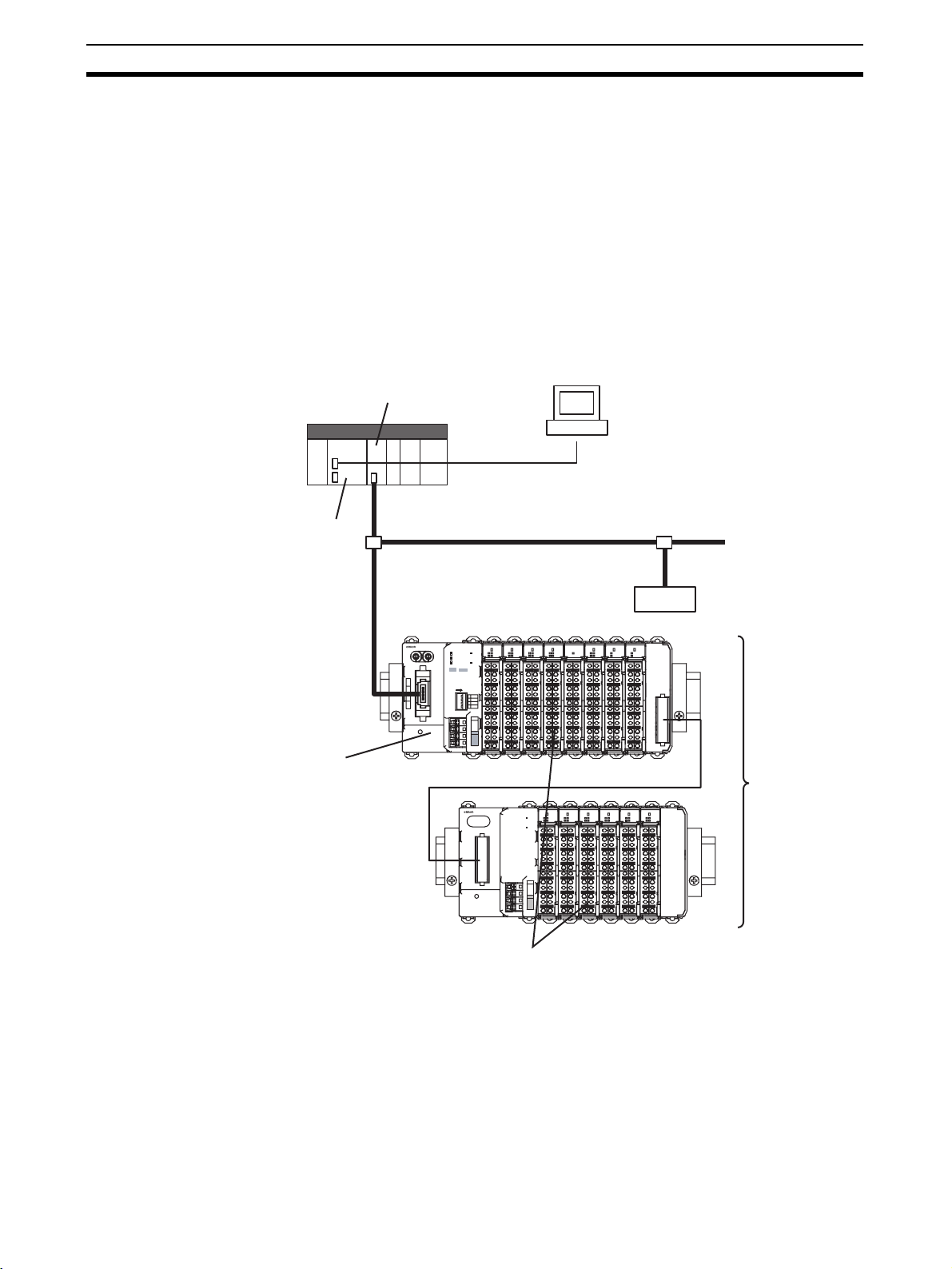
This is an example of a CompoNet SmartSlice System.
CompoNet Master Unit
PLC
Serial connection
CPU Unit
GRT1-CRT CompoNet
Communications Unit
CompoNet
Slave
ROS2
ROS2
GRT1-CRT
MS
UNIT PWR
NS
WORD
TS
NODE ADR
BS {
BD H
BD L
BS |
DC24V
INPUT
I/O PWR
×10
×1
[0-63]
INX
OUTX
ON
1
REGS
I/O
2
3
ADR
4
BACK
UNIT
V
V
I/O
V
V
DC24V
INPUT
OD4
ID4
ID4
TS
TS
TS
0
0
1
1
0
1
2
2
2
3
3
3
B1
B1
B1
A1
A1
A1
B2
B2
B2
A2
A2
A2
B3
B3
B3
A3
A3
A3
B4
B4
B4
A4
A4
A4
B5
B5
B5
A5
A5
A5
B6
B6
B6
A6
A6
A6
OD4
OD4
PD2
TS
TS
I/O PWR
0
0
1
1
2
2
3
3
B1
B1
A1
A1
A1
B2
B2
A2
A2
A2
B3
B3
A3
A3
A3
B4
B4
A4
A4
A4
B5
B5
A5
A5
A5
B6
B6
A6
A6
A6
TBR
TS
TS
0
0
1
1
B1
B1
B1
A1
A1
B2
B2
B2
A2
A2
B3
B3
B3
A3
A3
B4
B4
B4
A4
A4
B5
B5
B5
A5
A5
B6
B6
B6
A6
A6
Slice I/O Terminal
GRT1-TBL
ID4
TS
0
1
UNIT PWR
2
3
I/O PWR
B1
A1
B2
A2
B3
A3
B4
UNIT
A4
V
V
B5
I/O
A5
V
V
B6
A6
DC24V
INPUT
OD4
ID4
TS
TS
TS
0
1
0
0
1
1
2
2
3
2
3
3
B1
B1
B1
A1
A1
A1
B2
B2
B2
A2
A2
A2
B3
B3
B3
A3
A3
A3
B4
B4
B4
A4
A4
A4
B5
B5
B5
A5
A5
A5
B6
B6
B6
A6
A6
A6
END
TS
TS
0
1
0
1
2
3
2
3
B1
B1
A1
A1
B2
B2
A2
A2
B3
B3
A3
A3
B4
B4
A4
A4
B5
B5
A5
A5
B6
B6
A6
A6
OD4
OD4
ID4
Slice I/O Units
You can connect a maximum of 64 Slice I/O Units to one
CompoNet Communications Unit.
2
Page 22

Features of the CompoNet SmartSlice I/O Terminals Section 1-2
1-2 Features of the CompoNet SmartSlice I/O Terminals
This section tells you the features of a CompoNet SmartSlice System.
Each SmartSlice I/O Terminal Is One CompoNet Node
You can control a CompoNet Communications Unit with a maximum of 64
connected SmartSlice I/O Units as one Slave from the CompoNet Master
Unit.
Remote I/O Communications
You can use remote I/O communications to share I/O data between the CompoNet Master Unit and the SmartSlice I/O Units through the CompoNet Communications Unit. You can also allocate status data of the CompoNet
Communications Unit in the CompoNet Master Unit. You can also use the CXIntegrator or explicit messages to allocate status information on the network
participation status of SmartSlice I/O Units in the CompoNet Master Unit.
Easy Startup
All you must do to start operation is to set the node address with the rotary
switches and to set the DIP switch. These switches are on the CompoNet
Communications Unit. When you turn ON the power supply, the CompoNet
Master Unit automatically reads the Unit configuration and allocates I/O to the
SmartSlice I/O Terminals. You do not have to set parameters with special software.
Easy I/O Connections
All SmartSlice I/O Units connected to the CompoNet Communications Unit
have screwless clamp terminals. All you must do is to put 10-mm ferrules on
the wires and then push the ferrules into the screwless clamp terminals. It is
not necessary to tighten screws.
Table Registration
You can use the DIP switch on the CompoNet Communications Unit to record
the connected SmartSlice I/O Units in a table. The table tells the sequence
and I/O capacity of each SmartSlice I/O Unit. After you complete registration,
the CompoNet Communications Unit will compare the configuration with the
table each time that the power is turned ON. You can set a status flag in the
CompoNet Master Unit to show when the configurations do not agree.
Back Up and Restore Parameters
You can use the DIP switch on the CompoNet Communications Unit to back
up the parameters in the I/O Units to memory in the CompoNet Communications Unit. You can do this for maintenance, for example, when you replace an
I/O Unit. You can also use the DIP switch to restore the parameters in the
CompoNet Communications Unit to the I/O Units after you replace an I/O Unit.
Online Replacement of I/O Units
SmartSlice I/O Units have a base block, main block, and terminal block. You
can disconnect these blocks. With this block structure, you do not have to turn
OFF the Unit power supply to replace SmartSlice I/O Units.
Note You must turn OFF the I/O power supply to the SmartSlice I/O Unit before you
replace it. If there is external power to a terminal on the SmartSlice I/O Unit,
also turn OFF the external power before you replace the SmartSlice I/O Unit.
Automatic Baud Rate Recognition
The CompoNet Communications Unit automatically finds the communications
baud rate of the CompoNet Master Unit. It is not necessary to set the baud
rate.
3
Page 23

Features of the CompoNet SmartSlice I/O Terminals Section 1-2
Software Setting of I/O Allocations
You can record the node addresses and I/O configurations of Dummy Units in
the registration table to prepare for expansion of SmartSlice I/O Units. When
you add the I/O Units, it will not be necessary for you to set the node
addresses or I/O configurations. It will also not be necessary to change the
ladder programming very much. You can also write the ladder programming
for the full configuration and set the Units that you will add as Dummy Units.
When you change the unit configuration, it will not be necessary to change the
I/O map.
Unit Conduction Time Monitor
The Unit Conduction Time Monitor records the total time that the internal circuit power in DeviceNet Communications Unit is ON. You can set a threshold
in the CompoNet Communications Unit to tell the CompoNet Master Unit
when the conduction time is longer than the threshold. You can set the threshold or read the conduction time with the CX-Integrator or with an explicit message.
Unit Comments
You can set a comment (for example, a name or the application) for each
CompoNet Communications Unit to record the name in the CompoNet Communications Unit. You can use the comments to easily identify CompoNet
Communications Units when you set or monitor parameters with the CX-Integrator. You can set or read the comments with the CX-Integrator or with an
explicit message.
Communications Error History Monitor
There is a communications error history in the CompoNet Communications
Unit. It records the four newest errors in communications with the CompoNet
network and the 64 newest errors in communications in the SmartSlice I/O
Terminal. You can read the communications error status with the CX-Integrator or with an explicit message.
Last Maintenance Date
You can record the last date on which you did maintenance in the CompoNet
Communications Unit. You can write the last maintenance date with the CXIntegrator or with an explicit message.
4
Page 24

System Configuration Section 1-3
(4)
1-3 System Configuration
This is an example of a CompoNet SmartSlice System.
(7) CX-Integrator
(1) CompoNet Master Unit
PLC
Explicit message
Remote I/O
Communications
CompoNet
GRT1-CRT
WORD
NODE ADR
×10
(0-63)
BS {
BD H
BD L
BS |
DC24V
INPUT
(2) CompoNet Communications Unit
Left Turnback Unit
I/O data
Slave
ROS2
ROS2
OD4
OD4
OD4
ID4
ID4
TS
0
0
1
MS
UNIT PWR
2
2
3
NS
TS
I/O PWR
×1
OUTX
INX
B1
A1
A1
B2
A2
A2
ON
1
REGS
2
I/O
B3
3
ADR
A3
A3
4
BACK
B4
A4
A4
UNIT
V
V
B5
A5
A5
I/O
V
V
B6
A6
A6
DC24V
INPUT
PD2
TS
TS
TS
1
3
I/O PWR
0
0
0
1
1
2
2
2
3
3
B1
B2
B3
B4
B5
B6
B1
B1
B1
A1
A1
A2
A3
A4
A5
A6
A1
A1
B2
B2
B2
A2
A2
A2
B3
B3
B3
A3
A3
A3
B4
B4
B4
A4
A4
A4
B5
B5
B5
A5
A5
A5
B6
B6
B6
A6
A6
A6
TBR
TS
TS
TS
0
0
1
1
1
3
B1
B1
B1
A1
A1
B2
B2
B2
A2
A2
B3
B3
B3
A3
A3
B4
B4
B4
A4
A4
B5
B5
B5
A5
A5
B6
B6
B6
A6
A6
(4) Right Turnback Unit
(5) Turnback Cable (1 m)
(3) Slice I/O Units
OD4
OD4
ID4
GRT1-TBL
ID4
0
UNIT PWR
2
I/O PWR
A1
A2
A3
UNIT
A4
V
V
I/O
A5
V
V
A6
DC24V
INPUT
OD4
ID4
TS
TS
TS
0
1
1
0
0
1
2
2
3
3
2
3
B1
B1
B1
A1
A1
A1
B2
B2
B2
A2
A2
A2
B3
B3
B3
A3
A3
A3
B4
B4
B4
A4
A4
A4
B5
B5
B5
A5
A5
A5
B6
B6
B6
A6
A6
A6
END
TS
TS
TS
0
1
0
1
1
2
3
2
3
3
B1
B1
A1
A1
B2
B2
A2
A2
B3
B3
A3
A3
B4
B4
A4
A4
B5
B5
A5
A5
B6
B6
A6
A6
B1
B2
B3
B4
B5
B6
(6) End Unit
5
Page 25

System Configuration Section 1-3
No. Name Function
1 CompoNet Master Unit The CompoNet Master Unit controls the CompoNet network and transfers data
2 CompoNet Communications Unit
(GRT1-CRT)
3 SmartSlice I/O Units The SmartSlice I/O Units do communications with the CompoNet Master Unit
4 Turnback Units
(Right Turnback Unit: GRT1-TBR,
Left Turnback Unit: GRT1-TBL)
5 Turnback Cable (GCN2-100) You use a Turnback Cable to connect a Left Turnback Unit to a Right Turnback
6 End Unit (GRT1-END) You connect an End Unit to the end of the SmartSlice I/O Terminal.
7 CX-Integrator You use the CX-Integrator to write the parameters in the CompoNet Communi-
to and from all Slave Units.
The CompoNet Master Unit can send explicit messages to the CompoNet
Communication Unit.
The CompoNet Communications Unit is the interface with the CompoNet network. You connect it to the CompoNet Master Unit. You connect each CompoNet Communications Unit to SmartSlice I/O Units with the number of I/O points
which is necessary in each location. The CompoNet Communications Unit
does communications with the SmartSlice I/O Units.
The CompoNet Communications Unit temporarily keeps the I/O data from the
SmartSlice I/O Units which are connected to it. I/O data is transferred to and
from the CompoNet Master Unit all at one time during remote I/O communications.
through the CompoNet Communications Unit.
You can normally connect a maximum of 64 SmartSlice I/O Units to one Com-
poNet Communications Unit. There are restrictions in the number of SmartSlice I/O Units if the total data size is too large or power supply capacity is too
small.
You use a Turnback Unit to expand or divide a SmartSlice I/O Terminal.
Unit.
cations Unit and SmartSlice I/O Units and to monitor these parameters.
The CX-Integrator runs on a Windows computer.
6
Page 26

Specifications Section 1-4
1-4 Specifications
This section tells you the specifications of the SmartSlice System and the
CompoNet Communications Unit.
1-4-1 Specifications of the SmartSlice System
General Specifications
Item Specification
Ambient operating
temperature
Ambient operating
humidity
Ambient storage
temperature
Noise immunity Complies with IEC 61000-4-4, 2.0 kV.
Vibration resistance 10 to 60 Hz: 0.7-mm double amplitude
Withstand voltage 500 VAC (between isolated circuits)
Enclosure rating IP20
SmartSlice Bus Communications Specifications
Item Specification
Types of communications
Turnback Cables Length: 1 m, Maximum number of cables: 2
Connections
between Units in
SmartSlice I/O Terminal
Base block power
supply
Event messages You can use event messages.
−10 to 55°C (with no icing or condensation)
25% to 85%
−25 to 65°C (with no icing or condensation)
60 to 150 Hz: 50 m/s
I/O communications and message communications
Building-block structure with slide connectors
Voltage: 24 VDC, Current: 4 A
2
1-4-2 Specifications of the CompoNet Communications Unit
Item Specification
Model GRT1-CRT
I/O points Inputs: 32 bytes maximum (including status and areas which
the Unit does not use)
Output: 32 bytes maximum (including areas which the Unit
does not use)
Maximum number of
SmartSlice I/O Units
Status area 1 word (This word shows the status of the CompoNet Commu-
Parameter backup
and restore
Network power supply
I/O power supply 20.4 to 26.4 VDC
Baud rate The CompoNet Communications Unit uses the baud rate of
64 (Do not count the End Unit.)
nications Unit.)
You can back up or restore a maximum of 2 KB of data for one
CompoNet Communications Unit.
14 to 26.4 VDC
the CompoNet Master Unit (93. 75 kbps, 1.5 Mbps, 3 Mbps, or
4 Mbps).
7
Page 27

Specifications Section 1-4
Item Specification
Communications
media
Indicators MS (green/red): This indicator shows the status of the Compo-
Switches Rotary switches: There are two rotary switches. You use them
Connectors There is one CompoNet communications connector.
Terminals Clamp terminals for Unit power supply (24 VDC)
Power consumption 2.5 W
Power consumption
for each SmartSlice
I/O Terminal block
SmartSlice I/O Terminal blocks
Current consumption for I/O power
supply
Weight 125 g
Accessories None
You can use these cables:
2
Round Cable I (JIS C 3306, VCTF 2-core 0.75-mm
pair cable)
Round Cable II (JIS C 3306, VCTF 4-core 0.75-mm
pair cable)
Flat Cable I (without sheath, DCA4-4F10)
Flat Cable II (with sheath, DCA5-4F10)
Note The Round Cable I, Round Cable II, Flat Cable I, and
Flat Cable II are different types of cable. You must use a
Repeater to divide a branch line from the main line to
use more than one type of cable.
Net Communications Unit.
NS (green/red): This indicator shows the communications sta-
tus of the CompoNet network.
TS (green/red): This indicator shows the status of the Smart-
Slice I/O Terminal.
UNIT PWR (green): This indicator shows the status of the Unit
power supply.
I/O PWR (green): This indicator shows the status of the I/O
power supply.
to set the node address.
DIP switch: There is one DIP switch with four pins. You use
them to set the operating mode.
Clamp terminals for I/O power supply (24 VDC)
80 W max.
(You must divide the I/O Terminal into blocks to use more than
80 W.)
Main block and a maximum of two expansion blocks
4 A max.
twisted-
2
twisted-
8
Page 28
Specifications Section 1-4
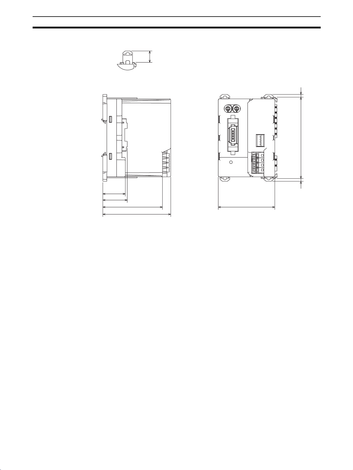
1-4-3 Dimensions
12
3
23.1
25.1
61.2
69.7
384
58
(mm)
9
Page 29

Specifications Section 1-4
10
Page 30

SECTION 2
Nomenclature and Functions
This section tells you about the names and functions of the parts of the CompoNet Communications Unit.
2-1 Nomenclature . . . . . . . . . . . . . . . . . . . . . . . . . . . . . . . . . . . . . . . . . . . . . . . . . 12
2-1-1 CompoNet Communications Unit . . . . . . . . . . . . . . . . . . . . . . . . . . 12
2-1-2 SmartSlice I/O Units. . . . . . . . . . . . . . . . . . . . . . . . . . . . . . . . . . . . . 13
2-2 Indicators. . . . . . . . . . . . . . . . . . . . . . . . . . . . . . . . . . . . . . . . . . . . . . . . . . . . . 14
2-2-1 MS Indicator . . . . . . . . . . . . . . . . . . . . . . . . . . . . . . . . . . . . . . . . . . . 14
2-2-2 NS Indicator . . . . . . . . . . . . . . . . . . . . . . . . . . . . . . . . . . . . . . . . . . . 15
2-2-3 TS Indicator . . . . . . . . . . . . . . . . . . . . . . . . . . . . . . . . . . . . . . . . . . . 16
2-2-4 UNIT PWR Indicator . . . . . . . . . . . . . . . . . . . . . . . . . . . . . . . . . . . . 17
2-2-5 I/O PWR Indicator . . . . . . . . . . . . . . . . . . . . . . . . . . . . . . . . . . . . . . 17
2-3 Switches . . . . . . . . . . . . . . . . . . . . . . . . . . . . . . . . . . . . . . . . . . . . . . . . . . . . . 18
2-3-1 Rotary Switches . . . . . . . . . . . . . . . . . . . . . . . . . . . . . . . . . . . . . . . . 18
2-3-2 DIP Switch . . . . . . . . . . . . . . . . . . . . . . . . . . . . . . . . . . . . . . . . . . . . 18
11
Page 31

Nomenclature Section 2-1
2-1 Nomenclature
This section tells you about the names and functions of the parts of the CompoNet Communications Unit.
2-1-1 CompoNet Communications Unit
(1)
WORD
NODE ADR
BS
BD H
BD L
BS
DC24V
INPUT
GRT1-CRT
×1
×10
[0-63]
(2)
IN
(3)
MS
UNIT PWR
NS
TS
I/O PWR
X_
X_
OUT
(7)
(4)
ON
1
REGS
I/O
2
3
ADR
4
BACK
UNIT
I/O
DC24V
INPUT
V
V
V
V
(5)
(6)
No. Name Function
1 CompoNet commu-
nications connector
Connect the communications cable for the CompoNet
network to this connector.
2 Rotary switches Set the node address of the CompoNet Communica-
tions Unit as a CompoNet slave.
3 Indicators These indicators show the status of communications
and the Units.
4 DIP switch Use this DIP switch to create the registration table, set
the I/O allocation mode, back up SmartSlice I/O Unit
parameters, and restore SmartSlice I/O Unit parameters.
5 Terminals for Unit
power supply
Use these terminals to send 24-VDC power to the internal circuits of the CompoNet Communications Units
and the SmartSlice I/O Units.
6 Terminals for I/O
power supply
Use these terminals to send 24-VDC power to the
external I/O which connect to the SmartSlice I/O Units.
7 Device label This label shows the I/O memory area that the Unit
uses. The Unit has an input area and an output area.
The sizes of the areas change if the SmartSlice I/O Unit
configuration changes.
12
Page 32

Nomenclature Section 2-1
2-1-2 SmartSlice I/O Units
A SmartSlice I/O Unit has three blocks. You can remove each block.
(1)
(2)
(3)
No. Name Function
1 Base Block This is the bus between the SmartSlice I/O Units.
You do not have to disconnect the Base Block when you
replace the Main Block, for example, when there is damage
to the Main Block.
2 Main Block This is the primary part of the SmartSlice I/O Unit.
3 Terminal Block This block has the terminals for the SmartSlice I/O Unit.
You do not have to disconnect the wires from the Terminal
Block when you replace the Main Block.
Refer to the GRT1 Series SmartSlice I/O Units Operation Manual (Cat. No.
W455) for information on each model of SmartSlice I/O Unit and specifications.
13
Page 33

Indicators Section 2-2
2-2 Indicators
This section tells you the specifications of the LED indicators on the front
panel of the CompoNet Communications Unit.
2-2-1 MS Indicator
The MS indicator shows the status of the CompoNet Communications Unit.
MS
UNIT PWR
NS
TS
Color Status
Green Lit Normal status
Red Lit Fatal error
--- Not lit No power
I/O PWR
• Unit hardware error
• Watchdog timer error
• EEPROM memory error
Flashing Non-fatal error
• Switch setting error (Pin 1 (REGS) and pin 2 (I/O) are ON
on the DIP switch when the Unit power supply came ON.)
• Logic error in parameter settings
• The Unit power supply is OFF.
• The Unit is being reset.
• Unit initialization is not complete.
14
Page 34

Indicators Section 2-2
2-2-2 NS Indicator
The NS indicator shows the communications status of the CompoNet network.
MS
UNIT PWR
NS
TS
Color Status
Green Lit The Unit is online and the communications connection is
Red Lit A fatal communications error occurred. (The CompoNet
--- Not lit The Unit is offline or the power supply is OFF.
I/O PWR
completed. (The network status is normal.)
Flashing The Unit is online but the communications connection is
not completed. (The baud rate is synchronized, but the
CompoNet Master Unit is completing the connection.)
Communications Unit found an error for which communications on the CompoNet network are not possible.)
• Communications error
• Duplication of node addresses
• Bus Off error
Flashing Non-fatal communications error
• Communications timeout
• There is no power supply to the CompoNet Communications Unit.
• The check for node address duplication is not completed
at the CompoNet Master Unit.
15
Page 35

Indicators Section 2-2
2-2-3 TS Indicator
The TS indicator shows the status of the communications with the SmartSlice
I/O Units.
MS
UNIT PWR
NS
TS
Color Status
Green Lit The CompoNet Communications Unit is in communica-
Red Lit • Fatal communications error
--- Not lit • No power
I/O PWR
tions with the SmartSlice I/O Units.
Flashing each
second
Flashing
each 0.5
second
Flashing
each 2
seconds
Flashing Non-fatal communications error
The SmartSlice I/O Units are joining communications at
this time.
• The CompoNet Communications Unit is backing up
parameters from the SmartSlice I/O Units.
• The CompoNet Communications Unit is restoring parameters to the SmartSlice I/O Units.
• The CompoNet Communications Unit could not back up
the parameters from the SmartSlice I/O Units.
• The CompoNet Communications Unit could not restore
the parameters to the SmartSlice I/O Units.
• The CompoNet Communications Unit could not make the
Registration Table.
• Pin 1 (REGS) of the DIP switch turned ON when pin 2
(I/O) was ON. You turn ON pin 1 to allocate I/O using
software. You turn ON pin 2 to allocate I/O with the Registration Table.
• Communications timeout
• Registration Table verification error
• A replaced SmartSlice I/O Unit is the incorrect model.
• The CompoNet Communications Unit did not start communications with the SmartSlice I/O Units.
• The CompoNet Communications Unit found an overcurrent.
16
Page 36

Indicators Section 2-2
2-2-4 UNIT PWR Indicator
The UNIT PWR indicator shows the status of the Unit power supply.
MS
UNIT PWR
NS
Color Status
Green Lit The 24-VDC Unit power supply to the CompoNet Commu-
--- Not lit The Unit power supply is OFF.
2-2-5 I/O PWR Indicator
The I/O PWR indicator shows the status of the I/O power supply.
TS
MS
NS
TS
I/O PWR
nications Unit is ON.
UNIT PWR
I/O PWR
Color Status
Green Lit The 24-VDC I/O power supply to the CompoNet Commu-
nications Unit is ON.
--- Not lit The I/O power supply is OFF.
17
Page 37

Switches Section 2-3
2-3 Switches
This section tells you the functions of the rotary switches and the DIP switch
on the front panel of the CompoNet Communications Unit.
2-3-1 Rotary Switches
Use the rotary switches to set the node address of the CompoNet Communications Unit as a slave on the CompoNet network. Set the node address as a
decimal number between 0 and 63.
Set the 10s digit on the left rotary switch and set the 1s digit on the right rotary
switch.
The setting of the switches is read when the Unit power supply turns ON.
×10
×1
2-3-2 DIP Switch
Use the DIP switch to create the registration table, set the I/O allocation
mode, back up SmartSlice I/O Unit parameters, and restore the SmartSlice
I/O Unit parameters.
ON
1
REGS
I/O
2
3
ADR
4
BACK
Note All pins on the DIP switch are OFF in the factory settings.
Pin 1: REGS Use pin 1 to make or change the Registration Table. The setting of pin 1 when
the Unit power supply turns ON enables or disables the Registration Table.
While the Unit power supply is ON, turn ON pin 1 to make the registration
table.
• The Pin Setting When the Unit Power Supply Turns ON
Pin setting Description
ON If there is no Registration Table, the CompoNet Communications Unit
OFF The CompoNet Communications Unit will disable the Registration
will record the connected SmartSlice I/O Units in a table. The table
tells the sequence and I/O capacity of each SmartSlice I/O Unit. If
there is a Registration Table, the CompoNet Communications Unit will
automatically compare the connected SmartSlice I/O Units with the
Registration Table. If the connected SmartSlice I/O Units do not agree
with the Registration Table, communications will not start for all
SmartSlice I/O Units.
Table and will do communications with all SmartSlice I/O Units.
18
• Changing the Pin Setting While the Unit Power Supply Is ON
Pin setting Description
OFF to ON The CompoNet Communications Unit makes the Registration Table.
Note The setting of pin 1 is enabled when pin 2 (I/O) is OFF (Automatic I/O Alloca-
tion Mode).
Page 38

Switches Section 2-3
Pin 2: I/O Use pin 2 to set the Software I/O Allocation Mode.
Pin setting Description
ON The Software I/O Allocation Mode is set.
You can make a Registration Table with the CX-Integrator to allocate
I/O. For each SmartSlice I/O Unit in the table, you can specify if the
Unit is installed or not. When you turn ON the power, the Communications Unit will do a check only for installed Units. The Units which are
not installed will have empty spaces in the I/O data for the CompoNet
Master Unit.
OFF The Automatic I/O Allocation Mode is set.
Use this mode to automatically detect SmartSlice I/O Units when the
power supply turns ON.
Note The CompoNet Communications Unit reads the setting of pin 2 when the Unit
power supply turns ON.
Pin 3: ADR Use pin 3 to control the automatic restore function.
Pin setting Description
ON If pin 1 (REGS) or pin 2 (I/O) is ON, the CompoNet Communications
Unit will automatically restore the parameters to the SmartSlice I/O
Units.
OFF The CompoNet Communications Unit will not restore the parameters.
Pin 4: BACK Use pin 4 to back up the parameters of all installed SmartSlice I/O Units.
If you turn pin 4 ON, OFF, ON in 3 s or less when pin 1 (REGS) or pin 2 (I/O)
is ON, the parameters of all the SmartSlice I/O Units will be backed up to the
CompoNet Communications Unit. While the parameters are being backed up,
the TS indicator will flash green each 0.5 s.
3 s or less
Pin setting
ON OFF ON
19
Page 39

Switches Section 2-3
20
Page 40

SECTION 3
Installing the Units
This section tells you how to install the CompoNet Communications Unit and SmartSlice I/O Units.
3-1 Installing a SmartSlice I/O Terminal. . . . . . . . . . . . . . . . . . . . . . . . . . . . . . . . 22
3-1-1 Installing the CompoNet Communications Unit . . . . . . . . . . . . . . . 22
3-1-2 Installing the First SmartSlice I/O Unit . . . . . . . . . . . . . . . . . . . . . . 23
3-1-3 Installing the Other SmartSlice I/O Units. . . . . . . . . . . . . . . . . . . . . 24
3-1-4 Installing the End Unit . . . . . . . . . . . . . . . . . . . . . . . . . . . . . . . . . . . 25
3-1-5 Installing the End Plates . . . . . . . . . . . . . . . . . . . . . . . . . . . . . . . . . . 26
3-2 Installing the Turnback Units . . . . . . . . . . . . . . . . . . . . . . . . . . . . . . . . . . . . . 27
21
Page 41

Installing a SmartSlice I/O Terminal Section 3-1
k
3-1 Installing a SmartSlice I/O Terminal
This section tells you how to install the CompoNet Communications Unit and
SmartSlice I/O Units.
3-1-1 Installing the CompoNet Communications Unit
You install the CompoNet Communications Unit and SmartSlice I/O Units on
DIN Track.
Necessary Tools
Name Model Remarks
35-mm DIN Tracks PFP-50N Length: 50 cm
PFP-100N Length: 100 cm
PFP-100N2 Length: 100 cm
End Plate PFP-M Two End Plates are necessary
Installation Direction You can install the SmartSlice I/O Terminal in these directions.
for each SmartSlice I/O Terminal block.
Installation Procedure
1,2,3... 1. Install the DIN Track.
22
Use one screw for each three holes in the DIN Track. There must be a
screw for each 105 mm or less.
DIN Trac
One screw for each three holes
Page 42

Installing a SmartSlice I/O Terminal Section 3-1
2. Press the CompoNet Communications Unit with force until you hear it lock
on the DIN Track.
After you install the CompoNet Communications Unit, make sure that it is
locked correctly on the DIN Track.
(2) Make sure that the installation hooks on
the Unit are locked on the DIN Track.
CompoNet Communications Unit
Installation hook
DIN Track
(1) Press with force.
Installation hook
Note If the installation hooks do not lock correctly, release the hooks first, push the
CompoNet Communications Unit against the DIN Track, and then lock the
hooks. The subsequent page shows how to release the hooks.
Removal Procedure Use a flat-blade screwdriver or equivalent tool to pull out the hooks. This will
unlock them. Then pull out the CompoNet Communications Unit in a perpendicular direction to the DIN Track.
Flat-blade screwdriver
Installation hook
DIN Track
Installation hook
CompoNet
Communications Unit
3-1-2 Installing the First SmartSlice I/O Unit
Press the SmartSlice I/O Unit along the side of the CompoNet Communications Unit to install it. It must engage with the CompoNet Communications
Unit.
Press the SmartSlice I/O Unit until you hear it lock on the DIN Track.
23
Page 43

Installing a SmartSlice I/O Terminal Section 3-1
CompoNet Communications Unit
Slice I/O Unit
3-1-3 Installing the Other SmartSlice I/O Units
Install the other SmartSlice I/O Units with the same procedure as the first
SmartSlice I/O Unit.
You can normally connect a maximum of 64 SmartSlice I/O Units to one CompoNet Communications Unit. (There are restrictions in the number of SmartSlice I/O Units if the total data size is too large or power supply capacity is too
small.)
24
Slice I/O Unit
Page 44

Installing a SmartSlice I/O Terminal Section 3-1
3-1-4 Installing the End Unit
You must install an End Unit (GRT1-END) to the end of the last block in the
SmartSlice I/O Terminal. You connect it with the same procedure as for
SmartSlice I/O Units.
Precaution for
Correct Usage
End Unit
• Make sure that the guides on the Units are locked together when you install
the Units.
Guide
25
Page 45

Installing a SmartSlice I/O Terminal Section 3-1
3-1-5 Installing the End Plates
You must install an End Plate on each end of each block in a SmartSlice I/O
Terminal. The End Plates prevent the blocks from moving.
1,2,3... 1. Put the bottom of the End Plate on the DIN Track. Then put the top of the
End Plate on the DIN Track and pull down on the End Plate.
2. Install one End Plate on the left side and one on the right side of the SmartSlice I/O Terminal. Then tighten the screws.
(2)
(1)
ROS2
ROS2
GRT1-CRT
MS
UNIT PWR
NS
WORD
TS
I/O PWR
×1
NODE ADR
×10
(0-63)
INX
OUTX
BS {
BD H
BD L
BS |
DC24V
INPUT
ON
1
REGS
I/O
2
3
ADR
4
BACK
UNIT
V
V
I/O
V
V
DC24V
INPUT
OD4
ID4
ID4
TS
TS
TS
0
0
1
1
0
1
2
2
2
3
3
3
B1
B1
B1
A1
A1
A1
B2
B2
B2
A2
A2
A2
B3
B3
B3
A3
A3
A3
B4
B4
B4
A4
A4
A4
B5
B5
B5
A5
A5
A5
B6
B6
B6
A6
A6
A6
OD4
OD4
PD2
TS
TS
I/O PWR
0
0
2
A1
A2
A3
A4
A5
A6
1
1
2
3
3
B1
B1
B1
A1
A1
B2
B2
B2
A2
A2
B3
B3
B3
A3
A3
B4
B4
B4
A4
A4
B5
B5
B5
A5
A5
B6
B6
B6
A6
A6
TBR
TS
TS
0
0
1
1
B1
B1
A1
A1
B2
B2
A2
A2
B3
B3
A3
A3
B4
B4
A4
A4
B5
B5
A5
A5
B6
B6
A6
A6
DIN Track
Screw
End Plate
End Plate
26
Page 46

Installing the Turnback Units Section 3-2
3-2 Installing the Turnback Units
Note You can use Turnback Units to expand or divide a SmartSlice I/O Terminal.
Install a Right Turnback Unit (GRT1-TBR) on the right side of the block. Install
a Left Turnback Unit (GRT1-TBL) on the left side of the expansion or divided
block. Then install the necessary SmartSlice I/O Units.
Connect the Right Turnback Unit to the Left Turnback Unit with a Turnback
Cable (GCN2-100). (Refer to Connecting the Turnback Cables on page 35.)
There can be three blocks in a SmartSlice I/O Terminal, one main block and
two expansion blocks.
Right side of block
Slice I/O Unit
Right Turnback Unit
Left side of expansion or divided block
Left Turnback Unit
Slice I/O Unit
Precaution for
Correct Usage
• You must install an End Unit (GRT1-END) on the end of the last block in the
SmartSlice I/O Terminal.
• There are limits for each block to the capacity of the Unit power supply and the
I/O power supply. If the Unit power consumption of the SmartSlice I/O Units in
one block is higher than 80 W, you must divide the SmartSlice I/O Terminal.
Refer to Precautions When Connecting the Power Supplies on page 36 for
more information.
27
Page 47

Installing the Turnback Units Section 3-2
28
Page 48

SECTION 4
Connecting the Units
This section tells you how to connect the CompoNet Communications Unit and SmartSlice I/O Units.
4-1 Connecting the Communications Cables . . . . . . . . . . . . . . . . . . . . . . . . . . . . 30
4-1-1 Using Flat Cables I/II . . . . . . . . . . . . . . . . . . . . . . . . . . . . . . . . . . . . 30
4-1-2 Using Round Cables I/II. . . . . . . . . . . . . . . . . . . . . . . . . . . . . . . . . . 30
4-2 Connecting the Power Supply Cables. . . . . . . . . . . . . . . . . . . . . . . . . . . . . . . 31
4-2-1 Types of Power Supply. . . . . . . . . . . . . . . . . . . . . . . . . . . . . . . . . . . 31
4-2-2 Recommended Power Supplies . . . . . . . . . . . . . . . . . . . . . . . . . . . . 31
4-2-3 Power Supply Terminals. . . . . . . . . . . . . . . . . . . . . . . . . . . . . . . . . . 31
4-2-4 Connecting the Unit Power Supply Cables. . . . . . . . . . . . . . . . . . . . 33
4-2-5 Connecting the I/O Power Supply Cables . . . . . . . . . . . . . . . . . . . . 34
4-3 Connecting the Turnback Cables . . . . . . . . . . . . . . . . . . . . . . . . . . . . . . . . . . 35
4-4 Precautions When Connecting the Power Supplies . . . . . . . . . . . . . . . . . . . . 36
4-5 Connecting the Signal Lines for External Devices . . . . . . . . . . . . . . . . . . . . . 38
29
Page 49

Connecting the Communications Cables Section 4-1
4-1 Connecting the Communications Cables
You can use different types of communications cable in a CompoNet network.
You can use the connector on the CompoNet Communications Unit for Flat
Cable or round cable.
4-1-1 Using Flat Cables I/II
1,2,3... 1. Connect a Flat Cable Branch Line Connector (DCN4-BR4 or DCN5-BR4)
to the communications cable. Refer to the CS/CJ-series CompoNet Master
Unit Operation Manual (Cat. No. W456) for the connection procedure.
2. Connect the CompoNet cable to the connector on the CompoNet Communications Unit. Push in until you hear the connector lock.
Flat Connector Plug
4-1-2 Using Round Cables I/II
1,2,3... 1. Connect a Screw Terminal Block Adapter (DCN4-TB4) to the communica-
tions connector on the CompoNet Communications Unit.
Open Connector
WORD
NODE ADR
DC24V
INPUT
GRT1-CRT
WORD
NODE ADR
BS
BD H
BD L
BS
DC24V
INPUT
GRT1-CRT
×1
×10
[0-63]
BS
BD H
BD L
BS
MS
NS
TS
×1
×10
[0-63]
X
IN
MS
UNIT PWR
NS
TS
I/O PWR
X
X
IN
OUT
ON
1
REGS
I/O
2
3
ADR
4
BACK
UNIT
V
V
I/O
V
V
DC24V
INPUT
UNIT PWR
OUT
ID4
TS
0
1
2
3
I/O PWR
X
A1
A2
ON
1
REGS
I/O
2
3
ADR
A3
4
BACK
A4
UNIT
V
V
A5
I/O
V
V
A6
DC24V
INPUT
ID4
ID4
TS
TS
0
1
0
1
2
2
3
3
B1
A1
A1
B2
A2
A2
B3
A3
A3
B4
A4
A4
B5
A5
A5
B6
A6
A6
OD4
ID4
TS
TS
0
0
1
0
1
2
3
B1
A1
B2
A2
B3
A3
B4
A4
B5
A5
B6
A6
OD4
TS
0
1
2
3
B1
A1
B2
A2
B3
A3
B4
A4
B5
A5
B6
A6
0
2
2
3
2
B1
B1
A1
A1
B2
B2
A2
A2
B3
B3
A3
A3
B4
B4
A4
A4
B5
B5
A5
A5
B6
B6
A6
A6
0
2
B1
A1
B2
A2
B3
A3
B4
A4
B5
A5
B6
A6
30
2. Open the terminal cover on the Screw Terminal Block Adapter and connect
the cable conductors to BDH (communications data high signal) and to
BDL (communications data low signal) on the terminal block. For Round
Cable II, also connect BS+ (communications power supply +) and BS
(communications power supply −).
Note Do not connect the BS+ and BS
−
− terminals.
Page 50

Connecting the Power Supply Cables Section 4-2
4-2 Connecting the Power Supply Cables
You connect the power supply cables to the power supply terminals on the
CompoNet Communications Unit. Network power is not necessary if you connect the Communications Unit to a host network.
4-2-1 Types of Power Supply
You must connect two types of power supply to the CompoNet Communications Unit.
■ Unit Power Supply
The Unit power supply is for the internal circuits in the CompoNet Communications Unit and connected SmartSlice I/O Units. The connectors on the Base
Blocks send the power to the SmartSlice I/O Units.
■ I/O Power Supply
The I/O power supply is for the external I/O devices which connect to the
SmartSlice I/O Units. The connectors on the Base Blocks send the power to
the SmartSlice I/O Units.
Unit power
supply (24 VDC)
I/O power
supply
(24 VDC)
CompoNet
Communications Unit
Terminals for
I/O power
supply
Internal
circuits
Terminals for Unit power supply
4-2-2 Recommended Power Supplies
Use an SELV power supply with overcurrent protection.
An SELV power supply has redundant or reinforced insulation between the I/
O, an output voltage of 30 Vr.m.s and a 42.4-V peak or maximum of 60 VDC.
We recommend these Power Supplies.
• S82K-10024 (from OMRON)
• S82J-10024D (from OMRON)
4-2-3 Power Supply Terminals
The power supply terminals on the CompoNet Communications Unit and
Turnback Units are screwless clamp terminals. If you connect ferrules on the
wires, all you must do to connect the wires is to push the ferrules into the terminals.
Internal
circuits
External
device
Slice I/O Units
End Unit
Slice bus
31
Page 51

Connecting the Power Supply Cables Section 4-2
Applicable Wires for Screwless Clamp Terminals
■ Types and Sizes
Type Applicable wire gauge
Stranded wires
Solid wires
Ferrules
■ Stripping Length for Stranded Wires and Solid Wires
■ Conductor Length for Ferrules
We recommend the ferrules in the table below.
Manufacturer Model Applicable wire Crimping Tool
Phoenix Contact AI0.5-10WH
Weidmüller H0.5/16 OR
AWG20 to AWG16 (0.5 to 1.25 mm2)
7 to 10 mm
8 to 10 mm
2
(AWG 20)
2
(AWG 18)
2
(AWG 16)
2
(AWG 18)
AI0.75-10GY
AI1.5-10BK
H0.75/16 W
H1.5/16 R
0.5 mm
0.75 mm
1.25 mm
0.5 mm2 (AWG 20)
0.75 mm
1.25 mm2 (AWG 16)
CRIMPFOX UD6 (order
number 1204436) or
CRIMPFOX ZA3 Series
PZ1.5 Crimping Tool (order
number 990599)
Connecting Wires or Ferrules
■ Connecting Wires with Ferrules
Push the ferrule fully into the wire hole of the screwless clamp terminal.
Push the ferrule fully into the hole.
32
Page 52

Connecting the Power Supply Cables Section 4-2
r
■ Connecting Wires without Ferrules
Press in the release button adjacent to the connection hole of the screwless
clamp terminal with a small flat-blade screwdriver. Then push the wire fully
into the wire hole of the screwless clamp terminal and release the button.
Small flat-blade screwdrive
Release button
Disconnecting Wires or Ferrules
Press in the release button adjacent to the connection hole of the screwless
clamp terminal with a small flat-blade screwdriver. Then pull out the wire or
ferrule and release the button.
Small flat-blade screwdriver
Release button
We recommend this screwdriver to connect or disconnect wires or ferrules.
Model: SZF1 Flat-blade Screwdriver
Manufacturer: Phoenix Contact
Side Front
0.6 mm
3.5 mm
4-2-4 Connecting the Unit Power Supply Cables
Connect the Unit power supply cable (24 VDC) to the power supply terminals
on the CompoNet Communications Unit. These terminals send power to the
internal circuits of the CompoNet Communications Units and the SmartSlice I/
O Units.
33
Page 53

Connecting the Power Supply Cables Section 4-2
Connection holes for power
supply wires or ferrules
UNIT
24 VDC
Unit power supply lines
+V
−V
I/O
+V
−V
DC24V
INPUT
Precaution for
Correct Usage
• Use an insulated power supply.
4-2-5 Connecting the I/O Power Supply Cables
Connect the I/O power supply cable (24 VDC) to the power supply terminals
on the CompoNet Communications Unit. These terminals send 24-VDC
power to the external I/O which connect to the SmartSlice I/O Units.
Connection holes for power
supply wires or ferrules
I/O power supply lines
24 VDC
Precaution for
Correct Usage
• Use an insulated power supply.
UNIT
+V
−V
I/O
+V
−V
DC24V
INPUT
34
Note (1) The Left Turnback Unit (GRT1-TBL) has the same type of power supply
terminals with screwless clamp terminals.
(2) The terminals on the CompoNet Communications Unit and Left Turnback
Unit (GRT1-TBL) are not the same as the terminals on the I/O Power
Feed Units (for example, the GRT1-PD2 and GRT1-PD8). Refer to the
GRT1 Series SmartSlice I/O Units Operation Manual (Cat. No. W455) for
the connection procedure.
Page 54

Connecting the Turnback Cables Section 4-3
4-3 Connecting the Turnback Cables
Note You use Turnback Units to expand or divide a SmartSlice I/O Terminal.
Connect the Right Turnback Unit (GRT1-TBR) on the block to the Left Turnback Unit (GRT1-TBL) on the subsequent block with a Turnback Cable
(GCN2-100). Press the connector on the cable into the connector on the Turnback Unit until you hear it lock.
You can connect a maximum of 2 expansion blocks for one CompoNet Communications Unit.
Right Turnback Unit
ROS2
ROS2
GRT1-CRT
MS
UNIT PWR
NS
WORD
TS
NODE ADR
BS {
BD H
BD L
BS |
DC24V
INPUT
I/O PWR
×10
×1
[0-63]
INX
OUTX
ON
1
REGS
I/O
2
3
ADR
4
BACK
UNIT
V
V
I/O
V
V
DC24V
INPUT
OD4
ID4
ID4
TS
TS
TS
0
0
1
1
0
1
2
2
2
3
3
3
B1
B1
B1
A1
A1
A1
B2
B2
B2
A2
A2
A2
B3
B3
B3
A3
A3
A3
B4
B4
B4
A4
A4
A4
B5
B5
B5
A5
A5
A5
B6
B6
B6
A6
A6
A6
OD4
OD4
PD2
TS
TS
I/O PWR
0
0
2
A1
A2
A3
A4
A5
A6
1
1
2
3
3
B1
B1
B1
A1
A1
B2
B2
B2
A2
A2
B3
B3
B3
A3
A3
B4
B4
B4
A4
A4
B5
B5
B5
A5
A5
B6
B6
B6
A6
A6
TBR
TS
TS
0
0
1
1
B1
B1
A1
A1
B2
B2
A2
A2
B3
B3
A3
A3
B4
B4
A4
A4
B5
B5
A5
A5
B6
B6
A6
A6
Precaution for
Correct Usage
GRT1-TBL
Left Turnback Unit
ID4
TS
0
1
UNIT PWR
2
3
I/O PWR
B1
A1
B2
A2
B3
A3
B4
UNIT
A4
V
V
B5
I/O
A5
V
V
B6
A6
DC24V
INPUT
OD4
ID4
TS
TS
TS
0
1
0
0
1
1
2
2
3
2
3
3
B1
B1
B1
A1
A1
A1
B2
B2
B2
A2
A2
A2
B3
B3
B3
A3
A3
A3
B4
B4
B4
A4
A4
A4
B5
B5
B5
A5
A5
A5
B6
B6
B6
A6
A6
A6
END
TS
TS
0
1
0
1
2
3
2
3
B1
B1
A1
A1
B2
B2
A2
A2
B3
B3
A3
A3
B4
B4
A4
A4
B5
B5
A5
A5
B6
B6
A6
A6
Turnback Cable
OD4
OD4
ID4
• The Turnback Cable does not send power. Connect the Left Turnback Unit to
the same power supply as the CompoNet Communications Unit.
35
Page 55

Precautions When Connecting the Power Supplies Section 4-4
4-4 Precautions When Connecting the Power Supplies
There are limits for each block to the capacities of the power supplies. The
total power consumption of the CompoNet Communications Unit and SmartSlice I/O Units must not be larger than 80 W. The total current consumption of
the I/O devices which connect to the SmartSlice I/O Units must not be larger
than 4 A.
If the current consumption or power consumption is too large, do the procedure below.
Total Unit Power Consumption
1,2,3... 1. Refer to Appendix D Power Consumption and Weight Tables and calculate
the total power consumption. Include the CompoNet Communications Unit
and the connected SmartSlice I/O Units.
2. If the total power consumption is larger than 80 W, connect a Right Turnback Unit (GRT1-TBR) where the total power consumption is 80 W or less.
Then connect a Left Turnback Unit (GRT1-TBL) to start a new block.
3. Connect the Right Turnback Unit to the Left Turnback Unit with a Turnback
Cable (GCN2-100).
4. Connect the Unit power supply (24 VDC) to the Unit power supply terminals on the Left Terminal Block. Connect the I/O power supply (24 VDC) to
the I/O power supply terminals on the Left Terminal Block
Total power consumption:
80 W maximum
Right Turnback Unit
Precaution for
Correct Usage
Total I/O Current Consumption
CompoNet
Communications Unit
I/O power
supply
(24 VDC)
I/O power
supply
Unit power
supply
(24 VDC)
(24 VDC)
Same power supply as CompoNet
Communications Unit
I/O
I/O I/O I/O I/O I/O
Left Turnback Unit
I/O
I/O I/O I/O I/O
• Connect all blocks to the same Unit power supply.
Cable
connector
Turnback Cable
End Unit
36
1,2,3... 1. Refer to Appendix E Total I/O Current Consumption Table and calculate the
total current consumption of all connected SmartSlice I/O Units. Include
the Turnback Unit.
2. If the total current consumption is larger than 4 A, do one of these procedures:
Page 56

Precautions When Connecting the Power Supplies Section 4-4
• Use Turnback Units to divide the SmartSlice I/O Terminal into two
blocks. Connect a Right Turnback Unit (GRT1-TBR) where the total
current consumption is 4 A or less. Then connect a Left Turnback Unit
(GRT1-TBL) to start a new block. Connect the Right Turnback Unit to
the Left Turnback Unit with a Turnback Cable (GCN2-100). Connect
the Unit power supply (24 VDC) to the Unit power supply terminals on
the Left Turnback Unit. Connect the I/O power supply (24 VDC) to the
I/O power supply terminals on the Left Turnback Unit.
• Add an I/O Power Feed Unit to start a new I/O power supply group.
Make sure that each group uses less than 4 A.
consumption:
4 A maximum
I/O Power Feed Unit Total current
End Unit
CompoNet
Inputs
Inputs
Outputs Outputs Outputs
Communications Unit
Unit power
supply
(24 VDC)
I/O power
supply
(24 VDC)
I/O power
supply
(24 VDC)
Note You can connect an I/O Power Feed Unit at the necessary location in the
SmartSlice I/O Terminal to divide the input and output power supplies.
37
Page 57

Connecting the Signal Lines for External Devices Section 4-5
4-5 Connecting the Signal Lines for External Devices
Connect the I/O signal lines from the external devices to the I/O terminals on
the SmartSlice I/O Units. The I/O terminals on the SmartSlice I/O Units are
the same type of screwless clamp terminal as on the CompoNet Communications Unit.
Refer to the GRT1 Series SmartSlice I/O Units Operation Manual (Cat. No.
W455) for more information.
38
Page 58

SECTION 5
Unit Settings and I/O Allocations
This section tells you how to set the unit address and unit number. It also tells how to allocate I/O in the CompoNet Master
Unit.
5-1 Setting the Node Addresses . . . . . . . . . . . . . . . . . . . . . . . . . . . . . . . . . . . . . . 40
5-2 Unit Numbers for SmartSlice I/O Units . . . . . . . . . . . . . . . . . . . . . . . . . . . . . 41
5-3 I/O Allocations to CompoNet Master Unit. . . . . . . . . . . . . . . . . . . . . . . . . . . 42
5-3-1 Overview of I/O Allocations. . . . . . . . . . . . . . . . . . . . . . . . . . . . . . . 42
5-3-2 Restrictions for Data Sizes and Number of Units. . . . . . . . . . . . . . . 44
5-3-3 Status Words . . . . . . . . . . . . . . . . . . . . . . . . . . . . . . . . . . . . . . . . . . . 46
5-3-4 Allocating I/O with the CX-Integrator . . . . . . . . . . . . . . . . . . . . . . . 51
39
Page 59

Setting the Node Addresses Section 5-1
5-1 Setting the Node Addresses
There are two types of node on a CompoNet Network: The slaves and a CompoNet Master Unit. The slaves connect to external I/O. The Master Unit controls the CompoNet Network and sends I/O data between the PLC and the
slaves.
A SmartSlice I/O Terminal is a slave on a CompoNet Network. You must set a
node address for it.
You can use the node address to find the first word that is allocated to the
SmartSlice I/O Terminal.
The SmartSlice I/O Terminal is a Word Slave.
CompoNet
Master Unit
XXXX CH
The node
address
sets the first
word.
CPU Unit
I/O memory
I/O words
for the Slice
I/O
Terminal
Setting Procedure
Rotary switches
CompoNet
Communications Unit
Slice I/O Terminal (Slave)
1,2,3... 1. Turn OFF the Unit power supply to the CompoNet Master Unit and the
CompoNet Communications Unit.
2. Set the 10s digit of the node address on the left rotary switch and set the
1s digit on the right rotary switch.
Set the node address to between 0 and 63. Do not set the same address
for more than one node (nodes for CompoNet Master Unit and slaves).
×10
×1
3. Turn ON the power supplies.
Note If you set a node address that is the same as a different node, the NS indica-
tor on the CompoNet Communications Unit will come ON in red. A network
configuration error will occur and normal communications will not be possible.
40
Page 60

Unit Numbers for SmartSlice I/O Units Section 5-2
5-2 Unit Numbers for SmartSlice I/O Units
Unit numbers identify the SmartSlice I/O Units connected in a SmartSlice I/O
Terminal.
The system automatically allocates the unit numbers for SmartSlice I/O Units.
The SmartSlice I/O Unit on the right side of the CompoNet Communications
Unit is Unit 1. The other SmartSlice I/O Units get unit numbers 2 to 64 in
sequence from the left side to the right side of the SmartSlice I/O Terminal.
The CompoNet Master Unit uses the unit numbers to allocate I/O.
The system automatically
allocates unit numbers from the
left side to the right side.
CompoNet
Communications
Unit
Note (1) The node address of the SmartSlice I/O Terminal has no relation to the
unit numbers of the SmartSlice I/O Units.
(2) The I/O Power Feed Units (for example, the GRT1-PD2 and GRT1-PD8)
do not get unit numbers.
I/O #1I/O #2I/O #3I/O
#4
I/O
#64
41
Page 61

I/O Allocations to CompoNet Master Unit Section 5-3
5-3 I/O Allocations to CompoNet Master Unit
The system allocates words in an Input Area and Output Area to the SmartSlice I/O Units using the node number of the SmartSlice I/O Terminal. These
words are in the I/O memory of the CPU Unit of the CompoNet Master Unit.
You can also use the CX-Integrator to set I/O allocations.
Note You can also use Software I/O Allocation Mode to allocate words to a Dummy
Unit. A Dummy Unit is a SmartSlice I/O Unit that is not connected in the
SmartSlice I/O Terminal. Refer to 6-7 Software Setting of I/O Allocations on
page 60 for more information.
5-3-1 Overview of I/O Allocations
This section gives an overview of I/O allocations to the CompoNet Master
Unit.
I/O memory
CPU Unit
First word
First word + 1
First word + 2
Bit 15
CompoNet
Communications
Unit
Allocation
sequence
A
A
Bit 0
BC
1. Status of CompoNet
Communications Unit (1 word)
2. I/O data for Slice I/O Units
3. Participation status of the
Slice I/O Units (8 words)
D
FE
Unit number
sequence
8
CD
B
E
F
42
Bit Units Word Units
Slice I/O Units
1. Status of the CompoNet Communications Unit
The Status Word shows the status of the SmartSlice I/O Units in the
SmartSlice I/O Terminal.
2. I/O Data for SmartSlice I/O Units
The system allocates the bits or words to the SmartSlice I/O Units in the
SmartSlice I/O Terminal in the same sequence as the unit numbers. It allocates lower bits first and words with lower addresses first.
Page 62

I/O Allocations to CompoNet Master Unit Section 5-3
• The system allocates 2 bits to each Bit Unit starting from the lower bits.
Bit Units are SmartSlice I/O Units that have two or more bits of I/O (for
example, the GRT1-ID4/OD4).
• The system allocates words to each Word Unit starting from words
with lower addresses. Word Units are SmartSlice I/O Units that have
one or more words of I/O (for example, the GRT1-AD2/DA2C).
Refer to the GRT1 Series SmartSlice I/O Units Operation Manual (Cat. No.
W455) for information on each Bit Unit and Word Unit model of SmartSlice
I/O Units and specifications.
3. Participation Status of the SmartSlice I/O Units
The system allocates 8 words for the participation status of the SmartSlice
I/O Units.
Allocation Example The system allocates words to the SmartSlice I/O Units in the sequence in
which they are connected (in the sequence of unit numbers). The models of
the SmartSlice I/O Units have no effect on the sequence of allocations.
Unless you use the CX-Integrator to set I/O allocations, the system always
allocates words in the same sequence starting from the first word for the node
address. The sequence is the status, left SmartSlice I/O Unit, subsequent
SmartSlice I/O Unit on the right side, other SmartSlice I/O Units. The system
allocates words to Input Units in the Input Area and to Output Units in the Output Area.
The system allocates words for status of the CompoNet Communications Unit
and the participation status of the SmartSlice I/O Units in the Input Area.
Slice I/O Units
Input Area
Bit 15
Word
First
word
Not
+1 #3
used.
+2
+3
These bits are not allocated
because the subsequent Unit is a
Word Unit.
8
Status of CompoNet
Communications Unit
#2
#4
#1
Data Patterns in I/O Memory
You can make these patterns in I/O memory for I/O allocations.
■ Input Area
■ Output Area
You can use the CX-Integrator to select from these patterns.
Bit 0
CompoNet Communications Unit
Unit 1
ID4
(4 bits)
Unit 2
ID4
(4 bits)
Unit 3
ID4
(4 bits)
Unit 4
AD2
(2 words)
Unit 5
OD4
(4 bits)
Unit 6
ROS2
(2 bits)
Word
First
word
Bit 15
Output Area
8
Not
used.
Bit 0
#6 #5
• Input data + Status of CompoNet Communications Unit (default setting)
• Input data + Status of CompoNet Communications Unit + Participation
status of SmartSlice I/O Units
• Output data only
43
Page 63

I/O Allocations to CompoNet Master Unit Section 5-3
Bits That Are Not
Used
The figure below shows a 4-bit Unit (Unit 5) that gets two bits in one word and
two bits in the subsequent word. The subsequent Unit (Unit 6) is a Word Unit
that gets two words. The system allocates the subsequent two full words to
this Unit and does not allocate the other bits in the +1 word.
Unit 8 in the figure is an 8-bit Unit. The system allocates only full words to 8bit Units. In this example, the system allocates the subsequent full word (the
+5 word) and does not allocate the other bits in the +4 word. (The first four bits
in the +4 word are for Unit 7.)
Configuration Example for Slice I/O Terminal
CompoNet
Communications
Unit
Word
#1
OD4
+0 #5 #4 #3 #2 #1
+1
+2
+3
+4 #7
+5 #8
#2
OD4
The system allocates four bits to a 4-bit
Unit two bits at a time. It allocates the bits
in sequence in the same word or in
different words.
Bit 15
#3
OD4
Not used.
Not used.
#4
ROS2
8
Not used.
#6
#5
OD4
#6
DA2
#5
Bit 0
#7
OD4#8OD8
The system allocates a
full word to a 8-bit Unit.
This makes bits that are
not used.
The system will not output data that you write
to these bits.
5-3-2 Restrictions for Data Sizes and Number of Units
There are restrictions on the SmartSlice I/O Units that you can connect to one
CompoNet Communications Unit. The restrictions are for the number and
models of SmartSlice I/O Units that you connect.
• You can connect a maximum of 64 SmartSlice I/O Units. (This does not
include the End Unit.)
• The Input Area must be no larger than 32 bytes. This includes bits for
Word Units, bits for Bit Units, status words, and bits that are not used.
• The Output Area must be no larger than 32 bytes. This includes bits for
Word Units, bits for Bit Units, and bits that are not used.
These are examples of the restrictions.
Permitted Configurations • Bit Input Units Only
CompoNet
Communications
Unit
4-point
DC Input
Unit
4-point
DC Input
Unit
60 Units
Four-point DC Input Unit (GRT1-ID4): 4 bits × 60 = 30 bytes in Input Area
4-point
DC Input
Unit
4-point
DC Input
Unit
End Unit
44
Two bytes are used for CompoNet Communications Unit status. The total is 32 bytes.
Page 64

I/O Allocations to CompoNet Master Unit Section 5-3
• Bit Output Units Only
CompoNet
Communications
Unit
4-point
DC Output
Unit
4-point
DC Output
Unit
64 Units
4-point
DC Output
Unit
4-point
DC Output
Unit
End Unit
Four-point DC Output Unit (GRT1-OD4): 4 bits × 64 = 32 bytes in Output Area
Two bytes are used for CompoNet Communications Unit status.
The total is 32 bytes in the Output Area and two bytes in the Input Area
• Word Input Units Only
CompoNet
Communications
Unit
Analog
Input
Unit
2-point
Analog
Input
Unit
7 Units
2-point
Analog
Input
Unit
2-point
Analog
Input
Unit
End Unit
2-point
Two-point Analog Input Unit (GRT1-AD2): 2 words (4 bytes) × 7 = 28 bytes in Input Area
Two bytes are used for CompoNet Communications Unit status. The total is 30 bytes.
• Word Output Units Only
2-point
CompoNet
Communications
Unit
Analog
Output
Unit
2-point
Analog
Output
Unit
2-point
Analog
Output
Unit
2-point
Analog
Output
Unit
End Unit
8 Units
Two-point Analog Output Unit (GRT1-DA2C): 2 words (4 bytes) × 8 = 32 bytes in Output Area
Two bytes are used for CompoNet Communications Unit status.
The total is 32 bytes in the Output Area and two bytes in the Input Area.
• Word Units and Bit Units Together
12 Units
4-point
DC Input
Unit
2-point
Analog
Input Unit
CompoNet
Communications
Unit
4-point
DC Input
Unit
Four-point DC Input Unit (GRT1-ID4): 4 bits × 12 = 6 bytes in Input Area
Analog Input Unit (GRT1-AD2): 2 words (4 bytes) × 6 = 24 bytes in Input Area
Two bytes are used for CompoNet Communications Unit status.
→ Total: 32 bytes in Input Area
6 Units
2-point
Analog
Input Unit
End Unit
45
Page 65

I/O Allocations to CompoNet Master Unit Section 5-3
y
• Input Units and Output Units
CompoNet
Communications
Unit
2-point
Analog
Input Unit
7 Units 2 Units
Two-point Analog Input Unit (GRT1-AD2): 2 words (4 bytes) × 7 + Communications
Unit status = 30 bytes in Input Area
Analog Output Unit (GRT1-DA2C): 2 words (4 bytes) × 2 = 8 bytes in Output Area
→ Totals: 30 bytes in Input Area
8 bytes in Output Area
Bad Configurations • Too Many Allocated Bits
2-point
CompoNet
Communications
Unit
Analog
Input
Unit
2-point
Analog
Input
Unit
Two-point Analog Input Unit (GRT1-AD2): 2 words (4 bytes) × 9 = 38 bytes in Input Area
Two bytes are used for CompoNet Communications Unit status.
• Too Many Units
2-point
CompoNet
Communications
Unit
Relay
Output
Unit
2-point
Relay
Output
Unit
2-point
Analog
Input Unit
9 Units
2-point
Analog
Output
Unit
2-point
Analog
Input
Unit
2-point
Analog
Output
Unit
2-point
Analog
Input
Unit
End Unit
End Unit
2-point
Relay
Output
Unit
2-point
Relay
Output
Unit
End Unit
5-3-3 Status Words
65 Units
Two-point Relay Output Unit (GRT1-ROS2): 2 bits × 65 = 17 bytes in Output Area
2 bytes in the Input Area
tes are used for CompoNet Communications Unit status.
Two b
• Too Many Allocated Bits with Bits That Are Not Used
2-point
CompoNet
Communications
Unit
4-point
DC Input
Unit
Analog
Input
Unit
12 Units (6 sets of a 4-point Input Unit and a 2-word Input Unit)
Four-point DC Input Unit (GRT1-ID4): 4 bits × 6 = 3 bytes in Input Area
Two-point Analog Input Unit (GRT1-AD2): 2 words (4 bytes) × 6 = 24 bytes in Input Area
Two bytes are used for CompoNet Communications Unit status.
→ Total: 29 bytes + 9 unused bytes = 38 bytes in Input Area
4-point
DC Input
Unit
2-point
Analog
Input
Unit
End Unit
The status words show the status of the SmartSlice I/O Units in the SmartSlice I/O Terminal, the connection status with the CompoNet Master Unit, and
the participation status.
There are two type of status: Status of the CompoNet Communications Unit
and the participation status of the SmartSlice I/O Units. There are different
words for each of these.
46
Page 66

I/O Allocations to CompoNet Master Unit Section 5-3
(
Status of the
CompoNet
Communications Unit
This status word shows the status of the SmartSlice I/O Units in the SmartSlice I/O Terminal, the connection status with the CompoNet Master Unit, and
other status.
By default, the system allocates 1 word of the Input Area.
The flags in this word show the status. You can use the CX-Integrator or
explicit messages to read these flags.
I/O memory in the CPU Unit
Bit 15
First word
First word +1
CompoNet Communications Unit
Input Area
Bit 0
The Input Area contains this
status and the I/O data.
Four-point Input Unit
Status
I/O data
End Unit
Status (16 bits)
I/O data
4 bits)
The table below gives the meanings of the flags.
Bit Description Meaning
0 SmartSlice Bus Communica-
tions Error Flag
OFF: Normal, ON: Communi-
cations error
1 Reserved. ---
2 SmartSlice I/O Unit Warning
Flag
OFF: Normal, ON: Error
3 Reserved. ---
4 SmartSlice I/O Unit Alarm
Flag
OFF: Normal, ON: Error
5 Reserved. ---
6 Reserved. ---
7 Reserved. ---
8 Reserved. ---
9 Reserved. ---
10 Reserved. ---
This flag turns ON when there is a communications error in the SmartSlice bus in the
SmartSlice I/O Terminal.
This flag turns ON when there is a minor
error in a SmartSlice I/O Unit. It will turn ON
when there is an error in one or more of the
SmartSlice I/O Units in the SmartSlice I/O
Te r mi n al.
This flag turns ON when there is a serious
error in a SmartSlice I/O Unit. It will turn ON
when there is an error in one or more of the
SmartSlice I/O Units in the SmartSlice I/O
Te r mi n al.
47
Page 67

I/O Allocations to CompoNet Master Unit Section 5-3
Bit Description Meaning
11 Reserved. ---
12 Unit Maintenance Flag
OFF: Normal, ON: Error
(more than threshold)
13 Automatic Restore Monitor
Flag
OFF: The parameters were
restored. ON: Restore operation error
14 CompoNet Communications
Unit Error Flag
OFF: Normal, ON: Error
15 I/O Refreshing Flag
OFF: I/O communications
stopped.
ON: I/O communications are
normal.
This flag turns ON when the operating time
is longer than the threshold set for the Unit
Conduction Time Monitor.
This flag turns ON when an error occurs in
the operation to automatically restore
parameters to the SmartSlice I/O Units.
This is an overview flag. It turns ON when
one of the flags in bits 0 to 4, 12, or 13 turns
ON.
This flag is ON while I/O data communications on the SmartSlice bus are normal.
Participation Status
of the SmartSlice I/O
Units
Participating Flags
Withdrawn Flags
These status words show the participation status of the SmartSlice I/O Units
that connect to the CompoNet Communications Unit.
The system allocates eight words for the participation status. It makes no difference how many SmartSlice I/O Units are in the SmartSlice I/O Terminal.
Four words contain the Participating Flags and the other four words contain
the Withdrawn Flags.
Bit 15
Word
+0
+1
+2
+3
+4
+5
+6
+7
* There is one Participating Flag and one Withdrawn Flag for each unit number (for each Slice I/O Unit).
(There are flags for 64 Slice I/O Units.)
#11 #10#12#13#14#15#16
#11 #10#12#13#14#15#16
Bit 8
The table below gives the meanings of the flags.
Flag Meaning
Participating Flag ON: The Unit is participating in communications (correctly
Withdrawn Flag ON: There is a communications error or the Unit joined and
allocated in the CompoNet Master Unit).
OFF: The Unit has not joined communications. (If the Regis-
tration Table is enabled and there was a verification error for
the Unit, the Participating Flag will be OFF.)
then disconnected from communications.
OFF: The Unit did not join communications at all or is partici-
pating in communications at this time.
Bit 0
#1#2#3#4#5#6#7#8#9
#17
#18#19#20#21#22#23#24#25#27 #26#28#29#30#31#32
#33#34#35#36#37#38#39#40#41#43 #42#44#45#46#47#48
#49#50#51#52#53#54#55#56#57#59 #58#60#61#62#63#64
#1#2#3#4#5#6#7#8#9
#17
#18#19#20#21#22#23#24#25#27 #26#28#29#30#31#32
#33#34#35#36#37#38#39#40#41#43 #42#44#45#46#47#48
#49#50#51#52#53#54#55#56#57#59 #58#60#61#62#63#64
48
Note (1) You must use the CX-Integrator to allocate words for the participation sta-
tus.
(2) The TS indicators on the SmartSlice I/O Units also show the status of the
communications and the status of the SmartSlice I/O Units.
Page 68

I/O Allocations to CompoNet Master Unit Section 5-3
Warning Status in the
CompoNet
Communications Unit
The warning status in the CompoNet Communications Unit tells you the minor
errors that occur in the CompoNet Communications Unit. The warning status
is not in an I/O area. You can access it only with an explicit message.
This table shows the warning status.
Bit Name Description
0 Manchester error rate
comparison value high
1 Reserved. Not used.
2 Reserved. Not used.
3 Unit total time warning This bit turns ON when the total operating time is
4 Reserved. Not used.
5 Reserved. Not used.
6 Reserved. Not used.
7 Reserved. Not used.
8 Reserved. Not used.
9 Reserved. Not used.
10 Reserved. Not used.
11 Reserved. Not used.
12 Reserved. Not used.
13 Reserved. Not used.
14 Reserved. Not used.
15 Reserved. Not used.
The code error rate is higher than the high comparison value.
higher than the threshold value.
Alarm Status in the
CompoNet
Communications Unit
The alarm status in the CompoNet Communications Unit tells you the serious
errors that occur in the CompoNet Communications Unit. The alarm status is
not in an I/O area. You can access it only with an explicit message.
This table shows the alarm status.
Bit Name Description
0 Manchester error rate
comparison value high
high
1 Non-volatile data error EEPROM memory error
2 Reserved. Not used.
3 Reserved. Not used.
4 Reserved. Not used.
5 Reserved. Not used.
6 Reserved. Not used.
7 Reserved. Not used.
8 DPRAM interface error The DPRAM interface sent a status error.
9 Reserved. Not used.
10 Reserved. Not used.
11 Reserved. Not used.
12 Reserved. Not used.
13 Reserved. Not used.
14 Reserved. Not used.
15 Reserved. Not used.
The code error rate is higher than the high high comparison value.
49
Page 69

I/O Allocations to CompoNet Master Unit Section 5-3
Doing a Check of the Communications Status with the CX-Integrator
You can use the CX-Integrator to do a check of the communications status.
1,2,3... 1. Start the CX-Integrator.
2. Right-click the icon of CompoNet Communications Unit and select Main-
tenance Information. (From the Maintenance Mode Window, double-click
the icon.) The Monitor Window will show.
3. Click the Status Tab. The window will show the communications status of
the SmartSlice I/O Units.
These are the meanings of the colors of the status indicators.
• Red: The Alarm Status Bit for the SmartSlice I/O Unit is ON.
• Yellow: The Warning Status Bit for the SmartSlice I/O Unit is ON.
• Blue: The SmartSlice I/O Unit is communicating as normal.
4. Click the Close Button.
Refer to the GRT1 Series SmartSlice I/O Units Operation Manual (Cat. No.
W455) for information on errors in SmartSlice I/O Units.
50
Page 70

I/O Allocations to CompoNet Master Unit Section 5-3
5-3-4 Allocating I/O with the CX-Integrator
You can use the CX-Integrator to set I/O allocations. Use this procedure.
1,2,3... 1. Start the CX-Integrator.
2. Double-click the icon of the CompoNet Master Unit. (In the Maintenance
−
Mode Window, right-click the icon and select Parameter
The Configuration Window will show.
Edit.)
3. Click the Software Setting Table Tab and set the areas, addresses, and
number of nodes for word outputs and word inputs. The area is the memory area in the CPU Unit and the address is the address of the first word
to allocate. “Node” is the number of words in the Input or Output Area.
If status words are necessary, set them too.
51
Page 71

I/O Allocations to CompoNet Master Unit Section 5-3
Note The “number of nodes” is the number of words in the Input and Output Areas
that the SmartSlice I/O Terminal uses. To find the number of words in the
Input and Output Areas, open the Configuration Window of the Communications Unit and click the I/O Map Tab. The tab page will show the number of
words in the Input Area and the Output Area.
Number of words in Input Area
Number of words in Output Area
4. Click the General Tab, and then click the Transfer [PC to Unit] Button.
The CX-Integrator will start to download the parameters.
5. Click the OK Button to complete the procedure.
52
Page 72

This section tells you about the many smart functions of the SmartSlice system.
6-1 Overview of Smart Functions . . . . . . . . . . . . . . . . . . . . . . . . . . . . . . . . . . . . . 54
6-2 Registration Table . . . . . . . . . . . . . . . . . . . . . . . . . . . . . . . . . . . . . . . . . . . . . . 54
6-2-1 Making a Registration Table . . . . . . . . . . . . . . . . . . . . . . . . . . . . . . . 54
6-2-2 Verifying the Registration Table. . . . . . . . . . . . . . . . . . . . . . . . . . . . 55
6-2-3 Clearing the Registration Table . . . . . . . . . . . . . . . . . . . . . . . . . . . . 56
6-3 Backup Function . . . . . . . . . . . . . . . . . . . . . . . . . . . . . . . . . . . . . . . . . . . . . . . 57
6-3-1 Backup Procedure. . . . . . . . . . . . . . . . . . . . . . . . . . . . . . . . . . . . . . . 57
6-3-2 Doing a Check of the Backup Results . . . . . . . . . . . . . . . . . . . . . . . 57
6-4 Automatic Restore Function . . . . . . . . . . . . . . . . . . . . . . . . . . . . . . . . . . . . . . 58
6-4-1 Restore Procedure. . . . . . . . . . . . . . . . . . . . . . . . . . . . . . . . . . . . . . . 58
6-4-2 Doing a Check of the Restore Results . . . . . . . . . . . . . . . . . . . . . . . 59
6-5 Replacing Units Online. . . . . . . . . . . . . . . . . . . . . . . . . . . . . . . . . . . . . . . . . . 59
6-6 Automatic Baud Rate Recognition . . . . . . . . . . . . . . . . . . . . . . . . . . . . . . . . . 59
6-7 Software Setting of I/O Allocations . . . . . . . . . . . . . . . . . . . . . . . . . . . . . . . . 60
6-7-1 Starting in Software I/O Allocation Mode . . . . . . . . . . . . . . . . . . . . 62
6-7-2 Making, Downloading, and Clearing the Software Setting Table . . 63
6-7-3 Showing the Settings . . . . . . . . . . . . . . . . . . . . . . . . . . . . . . . . . . . . 67
6-7-4 Editing Parameters of SmartSlice I/O Units. . . . . . . . . . . . . . . . . . . 70
6-8 Unit Conduction Time Monitor. . . . . . . . . . . . . . . . . . . . . . . . . . . . . . . . . . . . 71
6-8-1 Monitoring the Unit Conduction Time . . . . . . . . . . . . . . . . . . . . . . . 72
6-8-2 Setting the Threshold . . . . . . . . . . . . . . . . . . . . . . . . . . . . . . . . . . . . 72
6-9 Unit Comments . . . . . . . . . . . . . . . . . . . . . . . . . . . . . . . . . . . . . . . . . . . . . . . . 73
6-9-1 Reading Comments. . . . . . . . . . . . . . . . . . . . . . . . . . . . . . . . . . . . . . 74
6-9-2 Writing Comments . . . . . . . . . . . . . . . . . . . . . . . . . . . . . . . . . . . . . . 74
6-10 Network Communications Error History Monitor . . . . . . . . . . . . . . . . . . . . . 75
6-10-1 Reading the Error History. . . . . . . . . . . . . . . . . . . . . . . . . . . . . . . . . 75
6-11 I/O Communications Error History Monitor . . . . . . . . . . . . . . . . . . . . . . . . . 76
6-11-1 Reading the Error History. . . . . . . . . . . . . . . . . . . . . . . . . . . . . . . . . 77
6-12 Last Maintenance Date . . . . . . . . . . . . . . . . . . . . . . . . . . . . . . . . . . . . . . . . . . 77
6-12-1 Reading the Last Maintenance Date. . . . . . . . . . . . . . . . . . . . . . . . . 77
6-12-2 Writing the Last Maintenance Date . . . . . . . . . . . . . . . . . . . . . . . . . 78
SECTION 6
Smart Functions
53
Page 73

Overview of Smart Functions Section 6-1
6-1 Overview of Smart Functions
This section gives an overview of the smart functions of the CompoNet SmartSlice system.
Function Overview Method
Registration
Ta bl e
Backup Function You can read the parameter settings from all
Automatic
Restore Function
Replacing Units
Online
Automatic Baud
Rate Recognition
Software Setting
of I/O Allocations
Unit Conduction
Time Monitor
Unit Comments You can set a comment (for example, a
Network Communications
Error History
Monitor
I/O Communications Error History Monitor
Last Maintenance Date
The Registration Table contains information
on the SmartSlice I/O Units in the SmartSlice I/O Terminal.
SmartSlice I/O Units in the SmartSlice I/O
Terminal and save them.
You can automatically restore the parameter
settings that you backed up in the CompoNet Communications Unit.
You can replace a SmartSlice I/O Unit without turning OFF the power supply.
The CompoNet Communications Unit automatically uses the same baud rate as the
CompoNet Master Unit.
You can set Dummy Units (SmartSlice I/O
Units that are not installed at this time) in a
Software Setting Table. The settings include
the node address and I/O configuration
information.
The system calculates and records the time
that the internal power supply in the Unit is
ON in increments of 0.1-hour.
name) for each SmartSlice I/O Unit.
The system records the last four errors in
communications with the CompoNet network.
The system records the last 64 errors in
communications between the CompoNet
Communications Unit and the SmartSlice
I/O Units.
You can record the last date you did maintenance.
DIP switch
DIP switch
DIP switch
---
---
DIP switch
(You use the CXIntegrator to make,
download, and clear
the Software Setting Table.)
CX-Integrator or
explicit messages
CX-Integrator or
explicit messages
CX-Integrator or
explicit messages
CX-Integrator or
explicit messages
CX-Integrator or
explicit messages
6-2 Registration Table
You can use the DIP switch on the CompoNet Communications Unit to record
the connected SmartSlice I/O Units in a table. The table tells the sequence
and I/O capacity of each SmartSlice I/O Unit.
When the power is subsequently turned ON, the CompoNet Communications
Unit automatically compares the information in the Registration Table with the
connected SmartSlice I/O Units.
6-2-1 Making a Registration Table
Precaution for
Correct Usage
54
• Before making the Registration Table, make sure that all SmartSlice I/O Units
are participating in communications. The TS indicators must be lit in green.
• Before making the Registration Table, make sure that pin 2 (I/O) on the DIP
switch is OFF (Automatic I/O Allocation Mode). You cannot make the Registration Table if pin 2 is ON (Software I/O Allocation Mode).
Page 74

Registration Table Section 6-2
Turn ON pin 1 (REGS) on the DIP switch while the power to the SmartSlice
I/O Terminal is ON.
The CompoNet Communications Unit will read the I/O configuration information and make a Registration Table.
The CompoNet Communications Unit will overwrite a previous Registration
Table with the new one.
Power ON
Turn ON pin 1.
Registration Table
CompoNet
Communications Unit
The CompoNet Communications
Unit reads and saves the I/O
configuration information.
• Contents of Registration Table
The Registration Table contains the number of SmartSlice I/O Units and
the I/O size for each Unit.
Unit number
(from the left side)
#1 Input 4 points
#2 Input 4 points
#3 Output 4 points
#4 Output 2 points
6-2-2 Verifying the Registration Table
The CompoNet Communications Unit will verify the Registration Table if the
power turns ON when pin 1 (REGS) on the CompoNet Communications Unit
is ON. The CompoNet Communications Unit automatically compares the
information in the Registration Table with the connected SmartSlice I/O Units.
#1 #2 #3 #4
4-point
Input
Unit
4-point
Input
Unit
4-point
Output
Unit
2-point
Output
Unit
I/O Number of I/O
CompoNet
Registration Table
Unit number
(from the left
side)
#1
#2
#3
#4
Turn ON the power
when pin 1 is ON.
Number
I/O
of I/O
Input
4 points
Input
4 points
Output
Output
4 points
2 points
Communications Unit
The CompoNet Communications Unit
compares the I/O configuration with the
contents of the Registration Table.
#1 #2 #3 #4
4-point
Input
Unit
4-point
Input
Unit
2-point
Output
Unit
2-point
Output
Unit
The TS indicator on the CompoNet Communications Unit will flash in red if
there is one or more differences.
55
Page 75

Registration Table Section 6-2
If the TS indicator flashes in red, the CompoNet Communications Unit will not
communicate with the SmartSlice I/O Units.
TS indicator flashes in red.
#1 #2 #3 #4
4-point
Input
Unit
4-point
Input
Unit
2-point
Output
Unit
The number of outputs is
different (the Registration
Table does not agree with the
I/O configuration).
The CompoNet
Communications Unit will
not communicate with the
Slice I/O Units.
2-point
Output
Unit
Registration Table
Unit number
(from the left
side)
#1
#2
#3
#4
I/O
Input
Input
Output
Output
CompoNet
Communications Unit
Number
of I/O
4 points
4 points
4 points
2 points
Use the procedures in the table below if there are differences between the
Registration Table and the I/O configuration.
Cause Procedure
Unit failure caused a
SmartSlice I/O Unit to not
be in the Registration Table.
There is a SmartSlice I/O
Unit that is not in the Registration Table.
Correct the cause (for example, replace the Unit), turn
OFF pin 1 (REGS) on the CompoNet Communications
Unit, and reset the Unit power supply. Then turn ON pin
1 to make the Registration Table again.
Turn OFF pin 1 and reset the Unit power supply. Then
turn ON pin 1 to make the Registration Table again.
Note If you start with CompoNet Communications Unit with pin 1 ON and no Regis-
tration Table, the TS indicator will flash in red. This shows a Registration Table
Verification Error.
6-2-3 Clearing the Registration Table
To clear the Registration Table, turn ON the power supply to the CompoNet
Communications Unit when pin 1 (REGS) is OFF.
56
Page 76

Backup Function Section 6-3
6-3 Backup Function
The backup function saves the parameters from the SmartSlice I/O Units to
memory in the CompoNet Communications Unit.
If you back up the parameters, you can use the automatic restore function to
download the parameters in the CompoNet Communications Unit to the
SmartSlice I/O Units. This is useful when you replace SmartSlice I/O Units.
We recommend that you back up the parameters at a set interval to prevent
losing the parameter for SmartSlice I/O Unit failures.
Turn pin 4 OFF and
then ON when pin 1
or pin 2 is ON.
These conditions are necessary to back up the parameters. Do a check of
these conditions before you back up the parameters.
• Pin 1 (REGS) or pin 2 (I/O) on the DIP switch on the CompoNet Communications Unit must be ON.
• All SmartSlice I/O Units must be participating in communications (to back
up the parameters for all SmartSlice I/O Units at one time).
6-3-1 Backup Procedure
Turn pin 4 (BACK) OFF and then ON in 3 seconds.
Power ON
CompoNet
Communications Unit
The CompoNet Communications
Unit will back up the parameters
from all Slice I/O Units.
#1 #2 #3 #4
3 s or less
Pin setting
ON OFF ON
The CompoNet Communications Unit will start to back up the parameters.
Precaution for
Correct Usage
• Do not turn OFF the power supply or reset the CompoNet Communications
Unit from the CX-Integrator during the backup operation. The backup data will
not be correct.
6-3-2 Doing a Check of the Backup Results
The TS indicator on the CompoNet Communications Unit flashes green during the backup operation. The backup operation is completed when the TS
indicator goes OFF.
If the CompoNet Communications Unit could not back up the parameters, the
TC indicator will come ON in red for 2 seconds.
Note (1) To clear the backup data, reset the Unit power supply with pin 1 turned
OFF. This operation will clear the Registration Table and the backup data.
57
Page 77

Automatic Restore Function Section 6-4
s
(2) The CompoNet Communications Unit will clear the backup data if you
change the operating mode.
The CompoNet Communications Unit will clear the backup data if you
back up the parameters with pin 2 (I/O) ON (Software I/O Allocation
Mode) and then make the Registration Table from the CX-Integrator.
6-4 Automatic Restore Function
After you replace a SmartSlice I/O Unit, you can use the Automatic Restore
Function to automatically download the parameters in the CompoNet Communications Unit to the SmartSlice I/O Units.
Turn ON pin 3 when
pin 1 or pin 2 is ON.
These conditions are necessary to automatically restore the parameters. Do a
check of these conditions before you restore the parameters.
• There must be backup data in the CompoNet Communications Unit.
• Pin 1 (REGS) or pin 2 (I/O) on the DIP switch on the CompoNet Communications Unit must be ON.
• The new SmartSlice I/O Unit must have the same unit number and model
number as the previous SmartSlice I/O Unit, but a different serial number.
6-4-1 Restore Procedure
1,2,3... 1. Turn ON pin 3 (ADR) on the CompoNet Communications Unit to enable the
Automatic Restore Function.
2. Turn OFF the I/O power supply and replace the SmartSlice I/O Unit.
Refer to the GRT1 Series SmartSlice I/O Units Operation Manual (Cat. No.
W455) for information on how to replace SmartSlice I/O Units.
The CompoNet Communications Unit will detect the SmartSlice I/O Unit that
you replaced and it will download the parameters to it.
Power ON
CompoNet
Communications Unit
The CompoNet Communications
Unit will automatically download
the parameters to the new Unit.
#1 #2 #4
#3
Parameter
58
!WARNING Turn OFF the I/O power supply to a SmartSlice I/O Unit before you replace it.
Incorrect inputs, incorrect outputs, or electrical shock can occur if you do not
turn OFF the I/O power supply. If there is external power to a terminal for a
Relay Output Slave, for example, turn OFF the external power before you
replace the SmartSlice I/O Unit.
Precaution for
Correct Usage
• Do not turn OFF the power supply or reset the CompoNet Communications
Unit from the CX-Integrator during the restore operation. The restored data
will not be correct.
3. Turn ON the I/O power supply.
Page 78

Replacing Units Online Section 6-5
6-4-2 Doing a Check of the Restore Results
The TS indicator on the CompoNet Communications Unit flashes green during the restore operation. The restore operation is completed when the TS
indicator stops flashing.
If the CompoNet Communications Unit restored the parameters, it will reset
the SmartSlice I/O Units automatically and the TS indicator on the CompoNet
Communications Unit will come ON in green.
If the CompoNet Communications Unit could not restore the parameters, the
TS indicator on the CompoNet Communications Unit will come ON in red for 2
seconds. The Automatic Restore Monitor Flag (bit 13 in the status word for the
CompoNet Communications Unit) will also turn ON.
If the new SmartSlice I/O Unit is not the same model as the previous Unit, the
TS indicator on the CompoNet Communications Unit will flash in red.
6-5 Replacing Units Online
You can replace a SmartSlice I/O Unit in the SmartSlice I/O Terminal without
turning OFF the Unit power supply.
A SmartSlice I/O Unit has a base block, main block, and terminal block. When
you replace a SmartSlice I/O Unit, do not replace the base block and replace
the other blocks.
Communications with the other SmartSlice I/O Units will continue while you
replace the SmartSlice I/O Unit.
If you back up the parameters, you can turn ON pin 3 (ADR) with pin 1
(REGS) or pin 2 (I/O) ON to automatically restore the parameters.
Refer to the GRT1 Series SmartSlice I/O Units Operation Manual (Cat. No.
W455) for information on how to replace SmartSlice I/O Units.
!WARNING Turn OFF the I/O power supply to a SmartSlice I/O Unit before you replace it.
Incorrect inputs, incorrect outputs, or electrical shock can occur if you do not
turn OFF the I/O power supply. If there is external power to a terminal for a
Relay Output Slave, for example, turn OFF the external power before you
replace the SmartSlice I/O Unit.
Precaution for
Correct Usage
• Replace only one SmartSlice I/O Unit at a time.
• Always replace a SmartSlice I/O Unit with a Unit of the same model number. If
you use a different model, incorrect outputs can occur or restoring the parameters will not be possible.
• If it is necessary to replace the base block, turn OFF the unit power supply
and the I/O power supplies and replace the full SmartSlice I/O Unit. You can
also use the Automatic Restore Function after you replace the full SmartSlice
I/O Unit.
6-6 Automatic Baud Rate Recognition
The CompoNet Communications Unit will automatically detect the baud rate
set in the CompoNet Master Unit and use it for communications with the CompoNet Master Unit.
59
Page 79

Software Setting of I/O Allocations Section 6-7
The CompoNet Communications Unit will set the baud rate when it establishes communications with the CompoNet Master Unit. It will save the baud
rate until the power supply is turned OFF.
Note If you change the baud rate of the CompoNet Master Unit, reset the power
supply of the CompoNet Communications Unit.
6-7 Software Setting of I/O Allocations
You can set Dummy Units in a Software Setting Table for SmartSlice I/O Units
that are not in the SmartSlice I/O Terminal. The settings include the node
numbers and I/O configurations.
When you then add the SmartSlice I/O Units, it will not be necessary for you
to set the unit numbers or I/O configurations. It will also not be necessary to
change the ladder programming very much.
The Software Setting Table contains the I/O configuration information (including the Dummy Units). You can use the CX-Integrator to set or read it.
60
Page 80

Software Setting of I/O Allocations Section 6-7
The Slice I/O Units
that you will add
CompoNet
Communications Unit
Dummy Units
#2 #3
4-point
Input
Unit
CompoNet
Communications Unit
#1 #2 #3 #4
4-point
Input
Unit
4-point
Input
Unit
4-point
Input
Unit
#1
4-point
Input
Unit
#4 #5 #6
4-point
Input
Unit
4-point
4-point
Input
Input
Unit
Unit
Dummy Units
#7
4-point
Output
Unit
4-point
4-point
4-point
Input
Unit
#5 #6 #7 #8
4-point
Input
Unit
Input
Unit
Output
Unit
4-point
Input
Unit
#8
4-point
Output
Unit
4-point
Output
Unit
Software Setting Table
The Software Setting Table contains the I/O configuration, including Dummy Units.
First word +0
First word +1
Bit 15
#4 #3 #2 #1
8
#6 #5
Bit 0
First word +0
Bit 15
8
#8 #7
Bit 0
You can set Dummy Units to make the I/O configuration information and ladder programming for the maximum configuration. This will decrease the
effects of changes in the SmartSlice I/O Unit configuration on the I/O configuration information and ladder programming.
61
Page 81

Software Setting of I/O Allocations Section 6-7
CompoNet
Communications Unit
You use Dummy Units to set the maximum
I/O configuration.
#1 #2 #3 #4
4-point
4-point
4-point
Input
Unit
Input
Unit
Output
Unit
4-point
Output
Unit
#63 #64
4-point
Output
Unit
End Unit
4-point
Input
Unit
* You make the ladder programming for this configuration.
CompoNet
Communications Unit
#1 #2 #3 #4
4-point
Output
Unit
4-point
Output
Unit
4-point
4-point
Input
Input
Unit
Unit
You replace Dummy Units with Slice I/O Units as the Slice I/O Units become necessary.
Note There are no changes in the I/O configuration information when you replace a
Dummy Unit with a SmartSlice I/O Unit. You also do not have to change the
ladder programming.
6-7-1 Starting in Software I/O Allocation Mode
On the DIP switch, turn OFF pin 1 (REGS), turn ON pin 2 (I/O), and then turn
ON or reset the Unit power supply. The CompoNet Communications Unit will
start in Software I/O Allocation Mode and you can download the Software Setting Table.
Note (1) If pin 1 and pin 2 are ON when you turn ON the Unit power supply, the MS
indicator will flash in red to show an error. The operation will stop.
(2) If you turn ON pin 1 in Software I/O Allocation Mode, the TS indicator will
come ON in red for 2 seconds to show an error. The operation will continue.
(3) If you start in Software I/O Allocation Mode and there is no correct Reg-
istration Table in the CompoNet Communications Unit, there will be a
Registration Table Logic Error. The MS indicator will flash in red and I/O
operation will stop. If that occurs, make the Software Setting Table, download it, and turn ON or reset the Unit power supply.
(4) The unit numbers include unit numbers for Dummy Units.
#63 #64
4-point
Input
Unit
4-point
Output
Unit
End Unit
62
Page 82

Software Setting of I/O Allocations Section 6-7
6-7-2 Making, Downloading, and Clearing the Software Setting Table
You use the CX-Integrator to make, download, and clear the Software Setting
Table for a CompoNet Communications Unit.
Making the Software Setting Table
1,2,3... 1. Start the CX-Integrator.
2. Double-click the icon of the CompoNet Communications Unit. (In the Main-
−
tenance Mode Window, right-click the icon and select Parameter
The Configuration Window will show.
Edit.)
3. Click the I/O Module Tab and select the Use Software Configuration Mode
Check Box. This will enable the Mount Check Boxes.
63
Page 83

Software Setting of I/O Allocations Section 6-7
4. Select the Mount Check Boxes for all SmartSlice I/O Units in the SmartSlice I/O Terminal and clear the Mount Check Boxes for all Dummy Units.
Note By default, the Mount Check Boxes are selected for all SmartSlice I/O Units.
Downloading the Software Setting Table
1,2,3... 1. Start the CX-Integrator.
2. Double-click the icon of the CompoNet Communications Unit. (In the Maintenance Mode Window, right-click the icon and select Parameter
The Configuration Window will show.
−
Edit.)
64
3. Click the General Ta b .
Page 84

Software Setting of I/O Allocations Section 6-7
4. Click the Transfer [PC to Unit] Button. The CX-Integrator will download
the Software Setting Table to the CompoNet Communications Unit.
The CompoNet Communications Unit will automatically reset after the
Software Setting Table is downloaded. It will then download the parameters to the SmartSlice I/O Units. This enables the Software Setting Table.
5. Click the OK Button to complete the procedure.
Note (1) If the CompoNet Communications Unit is not in Software I/O Allocation
Mode when the parameters are downloaded, the CX-Integrator will download only the normal parameters.
(2) If you downloaded a Software Setting Table before, clear the Table, reset
the power supply, and then download the Table from the CX-Integrator
again.
65
Page 85

Software Setting of I/O Allocations Section 6-7
Clearing the Software Setting Table
1,2,3... 1. Start the CX-Integrator.
2. Double-click the icon of the CompoNet Communications Unit. (In the Main-
−
tenance Mode Window, right-click the icon and select Parameter
The Configuration Window will show.
Edit.)
3. Click the I/O Module Ta b .
4. Click the Clear Software Configuration Table Button.
The CompoNet Communications Unit will clear the Software Setting Table.
66
Note Clear the Software Setting Table and then set it again if you change the I/O
size of any Slave (for example, changing the I/O size for the GRT1-AD2 or
GRT1-TS2P). You must also do this when you change only an I/O size and do
not change the configuration.
Page 86

Software Setting of I/O Allocations Section 6-7
6-7-3 Showing the Settings
You can use the CX-Integrator to show the Unit configuration (including
Dummy Units) as an I/O map.
1,2,3... 1. Start the CX-Integrator.
2. Right-click the icon of CompoNet Communications Unit and select Main-
tenance Information. (From the Maintenance Mode Window, double-click
the icon.) The Monitor Window will show.
3. Click the I/O Module Tab. The Unit configuration information, including
Dummy Units, will show.
4. Click the Close Button to complete the procedure.
Note Click the I/O Map Tab from the Master Unit Configuration Window to show an
I/O map of the Unit configuration that is set. You can also save the Unit configuration in a CSV file.
67
Page 87

Software Setting of I/O Allocations Section 6-7
Saving the Unit Configuration in CSV Format
1,2,3... 1. Click the I/O Map Tab from the Master Unit Configuration Window and then
click the Export Button.
68
2. Save the Unit configuration to a file.
Page 88

Software Setting of I/O Allocations Section 6-7
The CSV file will contain the Units that are set in the input and output areas and
their I/O sizes.
69
Page 89

Software Setting of I/O Allocations Section 6-7
6-7-4 Editing Parameters of SmartSlice I/O Units
Installed Units Use this procedure to edit the parameters of installed Units. Installed Units are
those for which the Mount Check Box is selected in the I/O Module Tab Page
of the Configuration Window.
1. Start the CX-Integrator.
2. Double-click the icon of the CompoNet Communications Unit. (In the Maintenance Mode Window, right-click the icon and select Parameter
The Configuration Window will show.
−
Edit.)
3. Click the I/O Module Ta b .
4. Select the Unit to edit the parameters and click the Edit Button.
The Configuration Window will be displayed for the selected Unit. Refer to
the GRT1 Series SmartSlice I/O Units Operation Manual (Cat. No. W455)
for information the parameters.
Note An installed SmartSlice I/O Unit will return a normal response if you send an
explicit message directly to the Unit. The CX-Integrator is not required to do
this. Refer to the GRT1 Series SmartSlice I/O Units Operation Manual (Cat.
No. W455) for information on explicit messages.
Dummy Units You can edit the parameters for Dummy Units with the same procedure as
installed Units. You will not be able to upload or download the parameters. You
can save the parameters in network configuration files in the CX-Configurator.
70
Page 90

Unit Conduction Time Monitor Section 6-8
Note A Dummy Unit will return an error response if you send an explicit message
directly to the Unit. The CX-Integrator is not required to do this.
6-8 Unit Conduction Time Monitor
The Unit Conduction Time Monitor records the total time that the internal circuit power in CompoNet Communications Unit is ON. The time is in increments of 0.1 hours.
You can use the CX-Integrator to set a threshold for the conduction time. You
can set the threshold to between 0 and 429,496,729 hours. The threshold is
saved in the CompoNet Communications Unit. If the Unit conduction time
becomes larger than the threshold, the Unit Maintenance Flag will turn ON (bit
12 of the status word for the CompoNet Communications Unit) to notify the
CompoNet Master Unit.
You can read the Unit conduction time and the status flags with the CX-Integrator or explicit messages.
CompoNet Communications Unit
Unit Con-
CompoNet
network
duction Time
The CompoNet
Communications Unit records
the Unit Conduction Time.
Unit Conduction Time
Power supply for
internal circuits
ON
OFF
71
Page 91

Unit Conduction Time Monitor Section 6-8
6-8-1 Monitoring the Unit Conduction Time
1,2,3... 1. Start the CX-Integrator.
2. Right-click the icon of CompoNet Communications Unit and select Main-
tenance Information. (From the Maintenance Mode Window, double-click
the icon.) The Monitor Window will show.
You can monitor the Unit Conduction Time on the General Tab Page.
3. Click the Close Button to complete the procedure.
6-8-2 Setting the Threshold
1,2,3... 1. Start the CX-Integrator.
2. Double-click the icon of the CompoNet Communications Unit. (In the Maintenance Mode Window, right-click the icon and select Parameter
The Configuration Window will show.
−
Edit.)
72
Page 92

Unit Comments Section 6-9
3. On the General Tab Page, enter a value for the Unit Conduction Time
Threshold. The time can be between 0 and 429,496,729 hours. (The default value is 0 hours.)
4. Click the Transfer [PC to Unit] Button to download the setting, and then
5. Click the OK Button to complete the procedure.
6-9 Unit Comments
You can set a comment for each CompoNet Communications Unit to record
the name in the CompoNet Communications Unit. Each comment can be 32
characters long.
You can use the CX-Integrator or explicit messages to read and write unit
comments.
CompoNet Communications Unit
click the Reset Button to reset the CompoNet Communications Unit.
CX-Integrator
Unit comment (for example,
the equipment name)
CompoNet network
Unit comment
The CompoNet Communications
Unit records the Unit Comment.
73
Page 93

Unit Comments Section 6-9
6-9-1 Reading Comments
1,2,3... 1. Start the CX-Integrator.
2. Right-click the icon of CompoNet Communications Unit and select Main-
tenance Information. (From the Maintenance Mode Window, double-click
the icon.) The Monitor Window will show.
The General Tab Page shows the comment.
Note The comment shows by the icon of the CompoNet Communications Unit in
the Maintenance Mode Window.
3. Click the Close Button to complete the procedure.
6-9-2 Writing Comments
1,2,3... 1. Start the CX-Integrator.
2. Double-click the icon of the CompoNet Communications Unit. (In the Maintenance Mode Window, right-click the icon and select Parameter
The Configuration Window will show.
−
Edit.)
74
Page 94

Network Communications Error History Monitor Section 6-10
3. On the General Tab Page, enter the comment in the Comment Field.
4. Click the Transfer [PC to Unit] Button to download the setting, and then
click the Reset Button to reset the CompoNet Communications Unit.
5. Click the OK Button to complete the procedure.
6-10 Network Communications Error History Monitor
The CompoNet Communications Unit records the last four errors in communications between the CompoNet Master Unit and the CompoNet Communications Unit.
If there are more than four errors, the CompoNet Communications Unit
deletes previous errors.
You can read the error history with the CX-Integrator or explicit messages.
CompoNet network
Error in communications
CompoNet Communications Unit
The CompoNet Communications
Unit records previous errors in
communications.
Refer to 9-2-1 Communications Errors on CompoNet Networks on page 100
for information on the contents of the error history.
Error 1
Error 2
Error 3
Error 4
6-10-1 Reading the Error History
1,2,3... 1. Start the CX-Integrator.
75
Page 95

I/O Communications Error History Monitor Section 6-11
2. Right-click the icon of CompoNet Communications Unit and select Maintenance Information. (From the Maintenance Mode Window, double-click
the icon.)
The Monitor Window will show.
3. Click the Error History Ta b .
The window will show the last four errors in communications.
You can click the Clear Button to clear the error history.
4. Click the Close Button to complete the procedure.
6-11 I/O Communications Error History Monitor
The CompoNet Communications Unit records the last 64 errors in communications between the CompoNet Communications Unit and the SmartSlice I/O
Units and errors in the SmartSlice I/O Terminal.
If there are more than 64 errors, the CompoNet Communications Unit deletes
previous errors.
You can read the error history with the CX-Integrator or explicit messages.
CompoNet network
Error in communications
CompoNet Communications Unit
The CompoNet
Communications Unit
records previous errors in
communications.
Error 1
Error 64
76
Refer to 9-2-3 Errors in SmartSlice I/O Terminals on page 102 for information
on the contents of the error history.
Page 96

Last Maintenance Date Section 6-12
6-11-1 Reading the Error History
1,2,3... 1. Start the CX-Integrator.
2. Right-click the icon of the CompoNet Communications Unit and select
Maintenance Information. (From the Maintenance Mode Window, double-click the icon.) The Monitor Window will show.
3. Click the I/O Unit Error History Tab. The window will show the last 64 errors in communications.
You can click the Clear Button to clear the error history.
4. Click the Close Button to complete the procedure.
6-12 Last Maintenance Date
You can record the last date on which you did maintenance in the CompoNet
Communications Unit.
This lets you easily know the subsequent date for maintenance.
You can read the Last Maintenance Date with the CX-Integrator or explicit
messages.
6-12-1 Reading the Last Maintenance Date
1,2,3... 1. Start the CX-Integrator.
77
Page 97

Last Maintenance Date Section 6-12
2. Right-click the CompoNet Communications Unit and select Maintenance
Information. (In the Maintenance Mode Window, double-click the icon of
the CompoNet Communications Unit.) The Maintenance Information Window will show.
The General Tab Page will show the last maintenance date.
3. Click the OK Button to complete the procedure.
6-12-2 Writing the Last Maintenance Date
1,2,3... 1. Start the CX-Integrator.
2. Double-click the icon of the CompoNet Communications Unit. (In the Maintenance Mode Window, right-click the icon and select Parameter
The Configuration Window will show.
−
Edit.)
78
Page 98

Last Maintenance Date Section 6-12
3. Click the last maintenance date on the calendar that shows for the Last
Maintenance Date Field.
Click the arrow buttons at the top of the calendar to show other months.
Click the date at the bottom of the calendar to enter the date of today.
4. Click the Transfer [PC to Unit] Button to download the setting, and then
click the Reset Button to reset the CompoNet Communications Unit.
5. Click the OK Button to complete the procedure.
79
Page 99

Last Maintenance Date Section 6-12
80
Page 100

This section gives the procedures for and an example of operating a SmartSlice system.
7-1 Setting Example and Basic Procedures. . . . . . . . . . . . . . . . . . . . . . . . . . . . . . 82
7-1-1 System Setting Example. . . . . . . . . . . . . . . . . . . . . . . . . . . . . . . . . . 82
7-1-2 Basic Procedures. . . . . . . . . . . . . . . . . . . . . . . . . . . . . . . . . . . . . . . . 83
7-2 Preparing for Work . . . . . . . . . . . . . . . . . . . . . . . . . . . . . . . . . . . . . . . . . . . . . 84
7-2-1 Selecting the SmartSlice I/O Units. . . . . . . . . . . . . . . . . . . . . . . . . . 84
7-2-2 Making Sure That SmartSlice Specifications Are Applicable . . . . . 84
7-3 Hardware Connections and Settings . . . . . . . . . . . . . . . . . . . . . . . . . . . . . . . . 85
7-3-1 Installing a SmartSlice I/O Terminal . . . . . . . . . . . . . . . . . . . . . . . . 85
7-3-2 Connecting the Communications Cables and Power Cables . . . . . . 85
7-3-3 Setting the SmartSlice I/O Terminals . . . . . . . . . . . . . . . . . . . . . . . . 85
7-4 Starting Communications . . . . . . . . . . . . . . . . . . . . . . . . . . . . . . . . . . . . . . . . 87
7-4-1 Making the I/O Tables . . . . . . . . . . . . . . . . . . . . . . . . . . . . . . . . . . . 87
7-4-2 Starting the SmartSlice System . . . . . . . . . . . . . . . . . . . . . . . . . . . . 87
7-5 Making Sure That Operation Is Correct . . . . . . . . . . . . . . . . . . . . . . . . . . . . . 88
7-5-1 Unit Indications . . . . . . . . . . . . . . . . . . . . . . . . . . . . . . . . . . . . . . . . 88
7-5-2 Doing a Check of I/O . . . . . . . . . . . . . . . . . . . . . . . . . . . . . . . . . . . . 88
SECTION 7
Basic Operation
81
 Loading...