

Page 1

Cat. No. W04E-EN-03
SmartSlice GRT1-Series
GRT1-PRT
PROFIBUS
Communication Unit
OPERATION MANUAL
Page 2

SmartSlice GRT1-Series
GRT1-PRT
PROFIBUS Communication Unit
Operation Manual
Revised November 27, 2006
Page 3

ii
Page 4

Notice:
OMRON products are manufactured for use by a trained operator and only for the purposes described
in this manual.
The following conventions are used to classify and explain the precautions in this manual. Always
heed the information provided with them.
!DANGER Indicates information that, if not heeded, is likely to result in serious injury or loss of life.
!WARNING Indicates information that, if not heeded, could possibly result in serious injury or loss of
life.
!Caution Indicates information that, if not heeded, could possibly result in minor or relatively serious
injury, damage to the product or faulty operation.
OMRON Product References
All OMRON products are capitalized in this manual. The first letter of the word Unit is also capitalized
when it refers to an OMRON product, regardless of whether it appears in the proper name of the product.
The abbreviation Ch appears in some displays and on some OMRON products. It often means word
and is abbreviated as Wd in the documentation.
The abbreviation PLC means Programmable Logic Controller.
Visual Aids
The following headings appear in the left column of the manual to help you locate different types of
information.
Note Indicates information of particular interest for efficient and convenient opera-
tion of the product.
1, 2, 3...Indicates various lists such as procedures, checklists etc.
iii
Page 5

Trademarks and Copyrights
r
f
PROFIBUS, PROFIBUS FMS, PROFIBUS DP, and PROFIBUS PA are trademarks of PROFIBUS
International.
Microsoft, Windows, Windows NT, Windows 2000, Windows XP, Windows Explorer and ActiveX are
trademarks of Microsoft Corporation.
Other product names and company names in this manual are trademarks or registered trademarks of
their respective companies.
The copyright of the GRT1-PRT PROFIBUS Communication Unit belongs to OMRON Corporation.
OMRON, 2006
All rights reserved. No part of this publication may be reproduced, stored in a retrieval system, or transmitted, in any form, o
by any means, mechanical, electronic, photocopying, recording, or otherwise, without the prior written permission o
OMRON.
No patent liability is assumed with respect to the use of the information contained herein. Moreover, because OMRON is constantly striving to improve its high-quality products, the information contained in this manual is subject to change without
notice. Every precaution has been taken in the preparation of this manual. Nevertheless, OMRON assumes no responsibility
for errors or omissions. Neither is any liability assumed for damages resulting from the use of the information contained in
this publication.
iv
Page 6

TABLE OF CONTENTS
About this Manual . . . . . . . . . . . . . . . . . . . . . . . . . . . . . . . . . vii
PRECAUTIONS . . . . . . . . . . . . . . . . . . . . . . . . . . . . . . . . . . . xiii
1 Intended Audience . . . . . . . . . . . . . . . . . . . . . . . . . . . . . . . . . . . . . . . . . . . . . . . . . . . . . . . . . xiv
2 General Precautions . . . . . . . . . . . . . . . . . . . . . . . . . . . . . . . . . . . . . . . . . . . . . . . . . . . . . . . . xiv
3 Safety Precautions . . . . . . . . . . . . . . . . . . . . . . . . . . . . . . . . . . . . . . . . . . . . . . . . . . . . . . . . . xiv
4 Operating Environment Precautions . . . . . . . . . . . . . . . . . . . . . . . . . . . . . . . . . . . . . . . . . . . xv
5 Application Precautions . . . . . . . . . . . . . . . . . . . . . . . . . . . . . . . . . . . . . . . . . . . . . . . . . . . . .xvi
6 Conformance to EC Directives . . . . . . . . . . . . . . . . . . . . . . . . . . . . . . . . . . . . . . . . . . . . . . . xvii
SECTION 1
Features and Specifications . . . . . . . . . . . . . . . . . . . . . . . . . . 1
1-1 Overview of GRT1-Series SmartSlice I/O Units . . . . . . . . . . . . . . . . . . . . . . . . . . . . . . . . . . 2
1-2 GRT1-PRT PROFIBUS Communication Unit . . . . . . . . . . . . . . . . . . . . . . . . . . . . . . . . . . . 3
1-3 GRT1-PRT Configuration . . . . . . . . . . . . . . . . . . . . . . . . . . . . . . . . . . . . . . . . . . . . . . . . . . . 7
1-4 Basic Operating Procedure . . . . . . . . . . . . . . . . . . . . . . . . . . . . . . . . . . . . . . . . . . . . . . . . . .9
SECTION 2
Installation and Wiring . . . . . . . . . . . . . . . . . . . . . . . . . . . . . 11
2-1 Unit Components. . . . . . . . . . . . . . . . . . . . . . . . . . . . . . . . . . . . . . . . . . . . . . . . . . . . . . . . . . 12
2-2 Installing the GRT1-PRT Unit . . . . . . . . . . . . . . . . . . . . . . . . . . . . . . . . . . . . . . . . . . . . . . . . 16
2-3 Wiring the GRT1-PRT . . . . . . . . . . . . . . . . . . . . . . . . . . . . . . . . . . . . . . . . . . . . . . . . . . . . . .20
2-4 Setting up a PROFIBUS Network . . . . . . . . . . . . . . . . . . . . . . . . . . . . . . . . . . . . . . . . . . . . . 24
2-5 Installation of Configuration Software . . . . . . . . . . . . . . . . . . . . . . . . . . . . . . . . . . . . . . . . . 28
SECTION 3
Setup and Operation. . . . . . . . . . . . . . . . . . . . . . . . . . . . . . . . 31
3-1 Station Address Settings and I/O Allocation . . . . . . . . . . . . . . . . . . . . . . . . . . . . . . . . . . . . . 32
3-2 Unit Functions . . . . . . . . . . . . . . . . . . . . . . . . . . . . . . . . . . . . . . . . . . . . . . . . . . . . . . . . . . . . 36
3-3 Setup the GRT1-PRT Configuration . . . . . . . . . . . . . . . . . . . . . . . . . . . . . . . . . . . . . . . . . . . 42
3-4 Operating the Network . . . . . . . . . . . . . . . . . . . . . . . . . . . . . . . . . . . . . . . . . . . . . . . . . . . . . 52
3-5 Remote Communication Characteristics . . . . . . . . . . . . . . . . . . . . . . . . . . . . . . . . . . . . . . . . 55
SECTION 4
Troubleshooting and Maintenance . . . . . . . . . . . . . . . . . . . . 59
4-1 Overview . . . . . . . . . . . . . . . . . . . . . . . . . . . . . . . . . . . . . . . . . . . . . . . . . . . . . . . . . . . . . . . . 60
4-2 Troubleshooting using the LED Indicators . . . . . . . . . . . . . . . . . . . . . . . . . . . . . . . . . . . . . . 60
4-3 Other Errors . . . . . . . . . . . . . . . . . . . . . . . . . . . . . . . . . . . . . . . . . . . . . . . . . . . . . . . . . . . . . . 64
4-4 Maintenance. . . . . . . . . . . . . . . . . . . . . . . . . . . . . . . . . . . . . . . . . . . . . . . . . . . . . . . . . . . . . . 69
4-5 Replacing the Unit . . . . . . . . . . . . . . . . . . . . . . . . . . . . . . . . . . . . . . . . . . . . . . . . . . . . . . . . . 70
v
Page 7

TABLE OF CONTENTS
Appendices
A PROFIBUS Technology . . . . . . . . . . . . . . . . . . . . . . . . . . . . . . . . . . . . . . . . . . . . . . . . . . . . 71
B Slave Diagnostics Message . . . . . . . . . . . . . . . . . . . . . . . . . . . . . . . . . . . . . . . . . . . . . . . . . . 77
C Explicit Messages . . . . . . . . . . . . . . . . . . . . . . . . . . . . . . . . . . . . . . . . . . . . . . . . . . . . . . . . . 81
Index. . . . . . . . . . . . . . . . . . . . . . . . . . . . . . . . . . . . . . . . . . . . . 87
Revision History . . . . . . . . . . . . . . . . . . . . . . . . . . . . . . . . . . . 91
vi
Page 8

About this Manual
This manual describes the GRT1-PRT PROFIBUS Communication Unit for OMRON’s SmartSlice I/O
Units. It also describes how to install and operate the Unit.
Please read this manual carefully so that you understand the information provided before installing or
using the GRT1-PRT Unit. Start with the precautions in the following section. They describe the operating environment and application safety measures which must be observed prior to and when using
the GRT1-PRT Unit.
The sections of this manual are as follows:
Section 1 introduces the GRT1-PRT Unit.
Section 2 describes the installation and setup of the GRT1-PRT Unit.
Section 3 describes the FINS commands supported by the GRT1-PRT Unit.
Section 4 describes the operational aspects of the GRT1-PRT Unit.
Section 5 provides procedures for troubleshooting the GRT1-PRT Unit.
The Appendices contain information supplementary to the information in the main body of the manual. They are referred to in the various sections as required.
Manual Products Contents Cat. No.
GRT1-series Slice I/O Units
Operation Manual
CS/CJ-series PROFIBUS DP
Master Units Operation Manual
CX-Programmer
Operation Manual
C200H-series PROFIBUS DP
Master Units
Operation Manual
CJ-series PROFIBUS DP Slave
unit
Operation Manual
GRT1-series Devicenet Communications Unit
Operation Manual
GRT1-series SmartSlice I/O
Units
SYSMAC CS/CJ-series
CS1W-PRM21
CJ1W-PRM21 PROFIBUS DP
Units
SYSMAC WS02-CXP@@-E
CX-Programmer
SYSMAC C200H-series
C200HW-PRM21
SYSMAC CJ1-series
CJ1W-PRT21
GRT1-series GRT1-DRT
Devicenet Communications Unit
Describes the Installation and Operation of the GRT1 SmartSlice I/O Units.
Describes the installation and operation of the CS1W-PRM21 and CJ1WPRM21 PROFIBUS Units.
Provides information on how to use
the CX-Programmer, programming
software which supports CS1/CJ1series PLCs.
Describes the Installation and Operation of the C200HW-PRM21 PROFIBUS DP Master Units.
Describes the Installation and Operation of the CJ1W-PRT21 PROFIBUS
DP Slave Units.
Describes the Installation and Operation of the GRT1-DRT Devicenet Communications Unit.
W455-E1-@
W409-E2-@
W446-E1-@
W349-E2-@
W408-E2-@
W454-E1-@
!WARNING Failure to read and understand the information provided in this manual may result in per-
sonal injury or death, damage to the product, or product failure. Please read each section
in its entirety and be sure you understand the information provided in the section and
related sections before attempting any of the procedures or operations given.
vii
Page 9

viii
Page 10

Read and Understand this Manual
Please read and understand this manual before using the product. Please consult your OMRON
representative if you have any questions or comments.
Warranty and Limitations of Liability
WARRANTY
OMRON's exclusive warranty is that the products are free from defects in materials and workmanship for a
period of one year (or other period if specified) from date of sale by OMRON.
OMRON MAKES NO WARRANTY OR REPRESENTATION, EXPRESS OR IMPLIED, REGARDING NONINFRINGEMENT, MERCHANTABILITY, OR FITNESS FOR PARTICULAR PURPOSE OF THE
PRODUCTS. ANY BUYER OR USER ACKNOWLEDGES THAT THE BUYER OR USER ALONE HAS
DETERMINED THAT THE PRODUCTS WILL SUITABLY MEET THE REQUIREMENTS OF THEIR
INTENDED USE. OMRON DISCLAIMS ALL OTHER WARRANTIES, EXPRESS OR IMPLIED.
LIMITATIONS OF LIABILITY
OMRON SHALL NOT BE RESPONSIBLE FOR SPECIAL, INDIRECT, OR CONSEQUENTIAL DAMAGES,
LOSS OF PROFITS OR COMMERCIAL LOSS IN ANY WAY CONNECTED WITH THE PRODUCTS,
WHETHER SUCH CLAIM IS BASED ON CONTRACT, WARRANTY, NEGLIGENCE, OR STRICT
LIABILITY.
In no event shall the responsibility of OMRON for any act exceed the individual price of the product on which
liability is asserted.
IN NO EVENT SHALL OMRON BE RESPONSIBLE FOR WARRANTY, REPAIR, OR OTHER CLAIMS
REGARDING THE PRODUCTS UNLESS OMRON'S ANALYSIS CONFIRMS THAT THE PRODUCTS
WERE PROPERLY HANDLED, STORED, INSTALLED, AND MAINTAINED AND NOT SUBJECT TO
CONTAMINATION, ABUSE, MISUSE, OR INAPPROPRIATE MODIFICATION OR REPAIR.
ix
Page 11

Application Considerations
SUITABILITY FOR USE
OMRON shall not be responsible for conformity with any standards, codes, or regulations that apply to the
combination of products in the customer's application or use of the products.
At the customer's request, OMRON will provide applicable third party certification documents identifying
ratings and limitations of use that apply to the products. This information by itself is not sufficient for a
complete determination of the suitability of the products in combination with the end product, machine,
system, or other application or use.
The following are some examples of applications for which particular attention must be given. This is not
intended to be an exhaustive list of all possible uses of the products, nor is it intended to imply that the uses
listed may be suitable for the products:
• Outdoor use, uses involving potential chemical contamination or electrical interference, or conditions or
uses not described in this manual.
• Nuclear energy control systems, combustion systems, railroad systems, aviation systems, medical
equipment, amusement machines, vehicles, safety equipment, and installations subject to separate
industry or government regulations.
• Systems, machines, and equipment that could present a risk to life or property.
Please know and observe all prohibitions of use applicable to the products.
NEVER USE THE PRODUCTS FOR AN APPLICATION INVOLVING SERIOUS RISK TO LIFE OR
PROPERTY WITHOUT ENSURING THAT THE SYSTEM AS A WHOLE HAS BEEN DESIGNED TO
ADDRESS THE RISKS, AND THAT THE OMRON PRODUCTS ARE PROPERLY RATED AND
INSTALLED FOR THE INTENDED USE WITHIN THE OVERALL EQUIPMENT OR SYSTEM.
PROGRAMMABLE PRODUCTS
OMRON shall not be responsible for the user's programming of a programmable product, or any
consequence thereof.
x
Page 12

Disclaimers
CHANGE IN SPECIFICATIONS
Product specifications and accessories may be changed at any time based on improvements and other
reasons.
It is our practice to change model numbers when published ratings or features are changed, or when
significant construction changes are made. However, some specifications of the products may be changed
without any notice. When in doubt, special model numbers may be assigned to fix or establish key
specifications for your application on your request. Please consult with your OMRON representative at any
time to confirm actual specifications of purchased products.
DIMENSIONS AND WEIGHTS
Dimensions and weights are nominal and are not to be used for manufacturing purposes, even when
tolerances are shown.
PERFORMANCE DATA
Performance data given in this manual is provided as a guide for the user in determining suitability and does
not constitute a warranty. It may represent the result of OMRON's test conditions, and the users must
correlate it to actual application requirements. Actual performance is subject to the OMRON Warranty and
Limitations of Liability.
ERRORS AND OMISSIONS
The information in this manual has been carefully checked and is believed to be accurate; however, no
responsibility is assumed for clerical, typographical, or proofreading errors, or omissions.
xi
Page 13

Page 14

PRECAUTIONS
This section provides general precautions for using the GRT1-Series modules, Programmable Controllers and related
devices.
The information contained in this section is important for the safe and reliable operation of the GRT1-PRT
PROFIBUS Communication Unit. You must read this section and understand the information contained before
attempting to set up or operate a GRT1-PRT PROFIBUS Communication Unit and related systems.
1 Intended Audience . . . . . . . . . . . . . . . . . . . . . . . . . . . . . . . . . . . . . . . . . . . . . xiv
2 General Precautions . . . . . . . . . . . . . . . . . . . . . . . . . . . . . . . . . . . . . . . . . . . . xiv
3 Safety Precautions. . . . . . . . . . . . . . . . . . . . . . . . . . . . . . . . . . . . . . . . . . . . . . xiv
4 Operating Environment Precautions . . . . . . . . . . . . . . . . . . . . . . . . . . . . . . . . xv
5 Application Precautions . . . . . . . . . . . . . . . . . . . . . . . . . . . . . . . . . . . . . . . . . xvi
6 Conformance to EC Directives . . . . . . . . . . . . . . . . . . . . . . . . . . . . . . . . . . . . xvii
6-1 Applicable Directives . . . . . . . . . . . . . . . . . . . . . . . . . . . . . . . . . . . . xvii
6-2 Concepts . . . . . . . . . . . . . . . . . . . . . . . . . . . . . . . . . . . . . . . . . . . . . . xvii
6-3 Conformance to EC Directives . . . . . . . . . . . . . . . . . . . . . . . . . . . . . xviii
xiii
Page 15

Intended Audience
1 Intended Audience
This manual is intended for the following personnel, who must also have a
knowledge of electrical systems (an electrical engineer or the equivalent).
• Personnel in charge of installing FA systems.
• Personnel in charge of designing FA systems.
• Personnel in charge of managing FA systems and facilities.
2 General Precautions
The user must operate the product according to the performance specifications described in the operation manuals.
Before using the product under conditions which are not described in the
manual or applying the product to nuclear control systems, railroad systems,
aviation systems, vehicles, combustion systems, medical equipment, amusement machines, safety equipment, and other systems, machines, and equipment that may have a serious influence on lives and property if used
improperly, consult your OMRON representative.
Make sure that the ratings and performance characteristics of the product are
sufficient for the systems, machines, and equipment, and be sure to provide
the systems, machines, and equipment with double safety mechanisms.
This manual provides information for Installing and operating the OMRON
GRT1-PRT PROFIBUS Communication Unit. Be sure to read this manual
before attempting to use the Unit and keep this manual close at hand for reference during operation.
1
!WARNING It is extremely important that the Unit is used for its specified purpose and
under the specified conditions, especially in applications that can directly or
indirectly affect human life. You must consult your OMRON representative
before using it in a system in the above-mentioned applications.
3 Safety Precautions
!WARNING Never attempt to disassemble any Units or touch the terminal block while
power is being supplied. Doing so may result in serious electrical shock or
electrocution.
!WARNING Provide safety measures in external circuits (i.e., not in the Programmable
Controller), including the following items, to ensure safety in the system if an
abnormality occurs due to malfunction of the PLC or another external factor
affecting the PLC operation. Not doing so may result in serious accidents.
• Emergency stop circuits, interlock circuits, limit circuits, and similar safety
measures must be provided in external control circuits.
• The PLC will stop operation when its self-diagnosis function detects any
error or when a severe failure alarm (FALS) instruction is executed. As a
countermeasure for such errors, external safety measures must be provided to ensure safety in the system.
xiv
Page 16

Operating Environment Precautions
• The PLC outputs may remain ON or OFF due to deposits on or burning of
the output relays, or destruction of the output transistors. As a countermeasure for such problems, external safety measures must be provided
to ensure safety in the system.
• When the 24V DC output (service power supply to the PLC) is overloaded
or short-circuited, the voltage may drop and result in the outputs being
turned OFF. As a countermeasure for such problems, external safety
measures must be provided to ensure safety in the system.
• SmartSlice I/O Terminals will continue operating even if one or more I/O
Units is removed from or falls out of the SmartSlice I/O Terminal, i.e., the
other I/O Units will continue control operations, including outputs. As a
countermeasure for such a possibility, external safety measures must be
provided to ensure safety in the system.
!WARNING The CPU Unit refreshes I/O even when the program is stopped (i.e., even in
PROGRAM mode). Confirm safety thoroughly in advance before changing the
status of any part of memory allocated to Output Units, Special I/O Units, or
CPU Bus Units. Any changes to the data allocated to any Unit may result in
unexpected operation of the loads connected to the Unit. Any of the following
operations may result in changes to memory status.
4
• Transferring I/O memory data to the CPU Unit from a Programming
Device
• Changing present values in memory from a Programming Device
• Force-setting/-resetting bits from a Programming Device
• Transferring I/O memory files from a Memory Card or EM file memory to
the CPU Unit
• Transferring I/O memory from a host computer or from another PLC on a
network
4 Operating Environment Precautions
!Caution Do not operate the Unit in the following places:
• Locations subject to direct sunlight.
• Locations subject to temperatures or humidities outside the range specified in the specifications.
• Locations subject to condensation as the result of severe changes in temperature.
• Locations subject to corrosive or flammable gases.
• Locations subject to dust (especially iron dust) or salt.
• Locations subject to exposure to water, oil, or chemicals.
• Locations subject to shock or vibration.
Provide proper shielding when installing in the following locations:
• Locations subject to static electricity or other sources of noise.
• Locations subject to strong electromagnetic fields.
• Locations subject to possible exposure to radiation.
• Locations near to power supply lines.
xv
Page 17

Application Precautions
!Caution The operating environment of the GRT1-PRT PROFIBUS Communication
Unit can have a large effect on the longevity and reliability of the system.
Unsuitable operating environments can lead to malfunction, failure and other
unforeseeable problems with the system. Ensure that the operating environment is within the specified conditions at installation time and remains that
way during the life of the system. Follow all installation instructions and precautions provided in the operation manuals.
5 Application Precautions
Observe the following precautions when using the GRT1-PRT PROFIBUS
Communication Unit.
!WARNING Failure to abide by the following precautions could lead to serious or possibly
fatal injury. Always heed these precautions.
5
• Always connect to a class-3 ground (100
Units.
!Caution Failure to abide by the following precautions could lead to faulty operation of
the Unit or the system. Always heed these precautions.
• Install double safety mechanisms to ensure safety against incorrect signals that may be produced by broken signal lines or momentary power
interruptions.
• When adding a new device to the network, make sure that the baud rate
is the same as other stations.
• When adding a new SmartSlice I/O Unit to the Communication Unit, make
sure that the GRT1-PRT PROFIBUS Communication Unit is powered
down, to prevent unexpected results when starting up the new station.
• Use specified communication cables.
• Do not extend connection distances beyond the ranges given in the specifications.
• Always turn OFF the power supply to the personal computer, Slaves, and
Communication Units before attempting any of the following:
• Mounting or dismounting the GRT1-PRT PROFIBUS Communication
Unit, Power Supply Units, I/O Units, CPU Units, or any other Units.
• Assembling a Unit.
• Setting DIP-switches or rotary switches.
• Connecting or wiring the cables.
• Connecting or disconnecting connectors.
• Be sure that all the mounting screws, terminal screws, Unit mounting
screws, and cable connector screws are tightened to the torque specified
in the relevant manuals. Incorrect tightening torque may result in malfunction.
• Always use the power supply voltage specified in this manual.
• Double-check all the wiring and connection of terminal blocks and connectors before mounting the Units.
Ω or less) when installing the
xvi
Page 18

Conformance to EC Directives
6
• Take appropriate measures to prevent foreign objects from entering the
unit when mounting or wiring it. Failure to do so, may result in unit damage, electric shock or fire.
• Use crimp terminals for wiring. Do not connect bare stranded wires
directly to terminals.
• Observe the following precautions when wiring the communication cable.
• Separate the communication cables from the power lines or high-tension lines.
• Do not bend the communication cables.
• Do not pull on the communication cables.
• Do not place heavy objects on top of the communication cables.
• Be sure to wire communication cable inside ducts.
• Use appropriate communication cables.
• Take appropriate measures to ensure that the specified power with the
rated voltage and frequency is supplied in places where the power supply
is unstable. An incorrect power supply may result in malfunction.
• Install external breakers and take other safety measures against short-circuits in external wiring. Insufficient safety measures against short-circuits
may result in burning.
• Double-check all the wiring and switch settings before turning ON the
power supply.
• When transporting or storing the product, cover the PCB’s with electrically
conductive materials to prevent LSI’s and IC’s from being damaged by
static electricity, and also keep the product within the specified storage
temperature range.
• When transporting the Unit, use special packing boxes and protect it from
being exposed to excessive vibration or impacts during transportation.
• Do not attempt to disassemble, repair, or modify any Units.
6 Conformance to EC Directives
6-1 Applicable Directives
•EMC Directives
• Low voltage directive
6-2 Concepts
OMRON units complying with EC Directives also conform to related product
standards making them easier to incorporate in other units or machines. The
actual products have been checked for conformity to product standards.
Whether the products conform to the standards in the system used by the
customer, however, must be checked by the customer.
Product related performance of OMRON units complying with EC Directives
will vary depending on the configuration, wiring, and other conditions of the
equipment or control panel in which OMRON devices are installed. The customer must, therefore, perform final checks to confirm that units and the overall system conforms to product standards.
xvii
Page 19

A Declaration of Conformity for the GRT1-PRT PROFIBUS Communication
Unit can be requested at your nearest OMRON representative.
6-3 Conformance to EC Directives
PROFIBUS units should be installed as follows, for the complete configuration
to meet the EC directives:
1,2,3... 1. The units are designed for installation inside control panels. All units must
be installed within control panels.
2. Use reinforced insulation or double insulation for the DC power supplies
used for the communication power supply, internal circuit power supply,
and the I/O power supplies.
3. The GRT1-PRT PROFIBUS Communication Unit product meets the generic emission standard. However as EMC performance can vary in the final installation, additional measures may be required to meet the
standards. It should therefore be verified that the overall machine or device
also meets the relevant standards. You must therefore confirm that EC directives are met for the overall machine or device, particularly for the radiated emission requirement (10 m).
Page 20

SECTION 1
Features and Specifications
This section provides an introductory overview of the GRT1 series SmartSlice I/O Units and the GRT1-PRT PROFIBUS,
Communication Unit, its functions and how to setup and configure it for a PROFIBUS network.
1-1 Overview of GRT1-Series SmartSlice I/O Units . . . . . . . . . . . . . . . . . . . . . . 2
1-2 GRT1-PRT PROFIBUS Communication Unit . . . . . . . . . . . . . . . . . . . . . . . . 3
1-2-1 Features. . . . . . . . . . . . . . . . . . . . . . . . . . . . . . . . . . . . . . . . . . . . . . . 3
1-2-2 System Configuration . . . . . . . . . . . . . . . . . . . . . . . . . . . . . . . . . . . . 4
1-2-3 Specifications . . . . . . . . . . . . . . . . . . . . . . . . . . . . . . . . . . . . . . . . . . 5
1-3 GRT1-PRT Configuration . . . . . . . . . . . . . . . . . . . . . . . . . . . . . . . . . . . . . . . . 7
1-4 Basic Operating Procedure . . . . . . . . . . . . . . . . . . . . . . . . . . . . . . . . . . . . . . . 9
1-4-1 Overview. . . . . . . . . . . . . . . . . . . . . . . . . . . . . . . . . . . . . . . . . . . . . . 9
1-4-2 Preparations for Use . . . . . . . . . . . . . . . . . . . . . . . . . . . . . . . . . . . . . 10
1
Page 21
Overview of GRT1-Series SmartSlice I/O Units
S
)
(Up
)
O
x10x1x1
BUS
ON
+V
-V
DC24V
INPUT
REGS
NC
ADR
BACK
RUN
ERR
BF
TS
UNIT PWR
I/O PWR
1-1 Overview of GRT1-Series SmartSlice I/O Units
The GRT1-Series SmartSlice I/O Units are building-block style I/O devices,
which can be expanded in small I/O increments. This provides the possibility
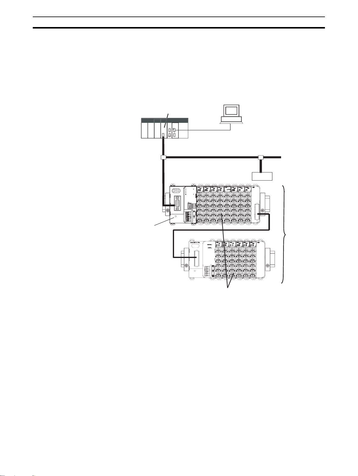
to configure I/O systems which exactly match the various customer applications. SmartSlice I/O Units communicate with the PROFIBUS DP-V1 Master
Unit by remote I/O communication through a PROFIBUS Communication
Unit. The figure below shows a typical I/O configuration.
PROFIBUS DP-V1 Master Unit
Section 1-1
PLC
GRT1-PRT PROFIBUS
Communication Unit
OMRON GRT1-PRT
5
6
4
3
2
9
1
0
x10
BUS
erial connection
(For setting, monitoring, and operating
ROFIBU
Slave
5
RUN
UNIT PWR
6
4
7
7
3
8
8
ERR
2
9
1
0
BF
TS
I/O PWR
ON
REGS
1
NC
2
ADR
3
BACK
4
+V
-V
DC24V
INPUT
SmartSlice I/
System
SmartSlice I/O Units
Up to 64 SmartSlice I/O Units can be connected to one PROFIBUS
Communication Unit
to 1,024 inputs or outputs can be connected
GRT1-Series SmartSlice
I/O Units
2
SmartSlice I/O configurations can be very compact, consisting of only a few
I/O points, but they can also be extended, to up to 64 I/O slices. The slice configuration can also be subdivided over two or more blocks using local extension units and extension cables, as shown in the figure above.
The GRT1-Series of SmartSlice I/O Units and Communication Units is constantly being expanded with new Units. Refer to the latest revisions of the
GRT1 Series SmartSlice I/O Units Operation Manual (W455) and the GRT1DRT DeviceNet Communication Unit Operation Manual (W454) for currently
available units in the GRT1-Series.
Page 22

GRT1-PRT PROFIBUS Communication Unit
1-2 GRT1-PRT PROFIBUS Communication Unit
1-2-1 Features
The GRT1-PRT PROFIBUS Communication Unit for SmartSlice I/O controls
data exchange between the PROFIBUS DP-V1 Master and SmartSlice I/O
Units over the PROFIBUS DP network. For an overview of the PROFIBUS
technology refer to Appendix A PROFIBUS Technology.
Section 1-2
Manage Multiple
SmartSlice I/O Units as
One Slave
I/O Data Exchange Cyclic I/O data exchange is used to exchange I/O data between the PROFI-
Simplified Startup The PROFIBUS Communication Unit can be set up easily, just by wiring the
Simplified I/O Wiring All of the SmartSlice I/O Units that connect to a PROFIBUS Communication
Table Registration The configuration of the SmartSlice I/O Units (mounting order and I/O size)
A single PROFIBUS Communication Unit with up to 64 connected SmartSlice
I/O Units can be managed as a single slave device from the PROFIBUS DPV1 Master.
BUS Master and SmartSlice I/O Units through the PROFIBUS Communication Unit. In addition to I/O data, various status information in the PROFIBUS
Communication Unit as well as in the individual I/O slices can be accessed
from the PROFIBUS DP-V1 Master Unit.
Unit, setting the PROFIBUS station address on the Unit’s rotary switches, and
making simple DIP switch settings.
The Unit’s configuration is read automatically when the power is turned ON
and I/O is also automatically allocated in the SmartSlice I/O Units. It is not
necessary to make any settings with a special Programming Device.
Unit are equipped with screw-less clamp terminal blocks. Wiring to external
I/O is accomplished just by inserting the wire into the terminals, eliminating
the need to tighten terminal screws.
connected to a PROFIBUS Communication Unit can be registered in a table
simply by switching a pin on the PROFIBUS Communication Unit’s DIP
switch. Once the table has been registered, the actual configuration is compared to the registered configuration each time that the power is turned ON. If
the configuration does not match, a status flag can be turned ON in the
PROFIBUS DP-V1 Master to indicate the error.
Communication Error Log
Monitor
Online Replacement of I/O
Units
Parameter Backup and
Restore
The communication error log in the PROFIBUS Communication Unit can
record the four most recent communication errors in the PROFIBUS DP network and the 64 most recent SmartSlice I/O Unit errors. The communication
error information (communication error cause code and communication power
supply voltage when error occurred) can be read with an explicit message
command or from the Configurator.
The SmartSlice I/O Unit’s circuit section can be removed, so it is not necessary to turn OFF the power to replace a Unit. Communication can be maintained in the remaining (connected) Units.
Before replacing a SmartSlice I/O Unit for maintenance, the parameter data
set in the I/O Unit can be backed up in the PROFIBUS Communication Unit
by switching a pin on the Communication Unit’s DIP switch. After the I/O Unit
has been replaced, another DIP switch operation can be used to select the
mode that automatically writes the backed-up parameter data to the appropriate Units.
3
Page 23
GRT1-PRT PROFIBUS Communication Unit
t
S
C
n
r
1
A
s
x10x1x1
BUS
ON
-V
DC24V
INPUT
REGS
NC
ADR
BACK
RUN
ERR
BF
TS
UNIT PWR
I/O PWR
Section 1-2
Automatic Baud Rate
Recognition
The PROFIBUS Communication Unit automatically detects the Master’s communication baud rate, so it is not necessary to set the baud rate. (If the Master’s baud rate has been changed, the PROFIBUS Communication Unit must
be turned OFF and then ON again to change its baud rate.)
1-2-2 System Configuration
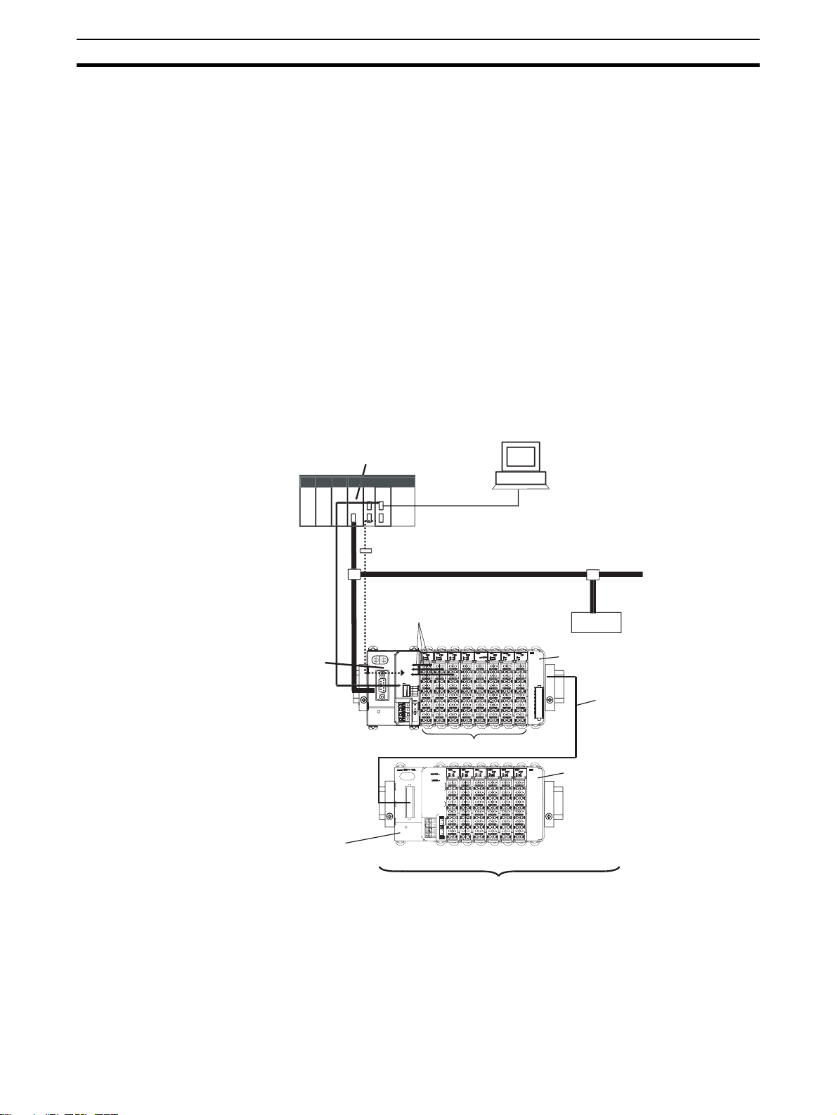
The PROFIBUS Communication Unit connects to the Master by a network
cable and it connects to the SmartSlice I/O Units by directly coupling the Units
with slide connectors.
I/O Data Exchange The I/O Unit data in the PROFIBUS Communication Unit is shared with the
Master’s Input and Output Areas through the PROFIBUS DP network. The I/O
Units’ data is collected in the PROFIBUS Communication Unit and exchanged
with the Master asynchronously.
Messaging Services The GRT1-PRT PROFIBUS Communication Unit also supports messaging
services, allowing the user to send acyclic message commands addressed to
the GRT1-PRT Unit or individual SmartSlice I/O Units.
x-PROFIBUS Configurato
J Series PROFIBUS DP-V1 Master Uni
Used to monitor operation and write
parameters to the SmartSlice I/O Units or
PROFIBUS Communication Unit.
PL
Remote I/O data is collected
from the connected
SmartSlice I/O Units and
exchanged with the Master Unit
GRT1-PRT PROFIBUS
Communication Unit
GRT1-TBL Left Turnback Unit
Note Always install an End Unit on the last I/O Unit in the system.
erial connectio
(For setting, monitoring, and operating)
ROFIBUS DP-V
cyclic message
PROFIBU
I/O data first goes to the
Communication Unit.
OMRON GRT1-PRT
RUN
UNIT PWR
5
5
6
6
4
4
7
7
3
3
ERR
8
8
2
2
9
9
1
1
0
0
BF
TS
I/O PWR
x10
ON
BUS
REGS
1
NC
2
ADR
3
BACK
4
-V
DC24V
INPUT
Slave
GRT1-TBR Right Turnback Unit
GCN2-100 Turnback Cable (1 m)
Up to 2 cables (2 m) can be used
per Communication Unit.
SmartSlice I/O Units
GRT1-END End Unit
Up to 64 SmartSlice I/O Units can be connected to one PROFIBUS Communication Unit.
(Up to 1,024 inputs or outputs can be connected.)
4
Page 24

GRT1-PRT PROFIBUS Communication Unit
1-2-3 Specifications
Functional Specifications
Item Specification
Unit type SmartSlice GRT1 series
Model GRT1-PRT
Mounting position DIN Rail mounted
Power supply 24 Vdc +10% -15% (20.4 to 26.4 Vdc)
Current consumption 103 mA (max), 90 mA typical at 24 Vdc
Dimensions (W x H x D) 58 x 80 x 70mm
Weight 135g (typical)
Installation
Ambient operating temperature –10 to 55° C (no icing or condensation)
Ambient operating humidity 25% to 85% Relative Humidity
Storage temperature –20 to 65° C (no icing or condensation)
Vibration resistance 10 to 57Hz, 0.7-mm amplitude
57 to 150Hz, acceleration: 49 m/s
Shock resistance
Dielectric strength 500 VAC (between isolated circuits)
Conformance to EMC and Electrical
safety standards
Enclosure rating IP20
Environment
Settings, rotary switches 2 Slave address rotary switches, range: 0 ~ 99 (Decimal)
Settings DIP-switches 4 DIP-switches on the front of the Unit:
Indicators 6 LEDs, indicating Unit status, Slice I/O status and PROFIBUS status:
PROFIBUS Connector 9-pin sub-D female connector (#4/40 UNC thread)
Power connector Screwless connectors. Unit power and I/O power are separated.
Front case
Number of connectable SmartSlice I/O
Units
Baud rate 3 Mbps
Communication signal level RS-485
Communication distance SmartSlice I/O Units: 64 Units coupled (about 2 m max.)
Turnback Cable Length 1 m max., up to 2 cables can be connected.
SmartSlice I/O Unit connections Building-block style configuration with slide connectors (Units connect
Baseblock power supply Voltage: 24 V DC
Event messaging Supported.
SmartSlice I/O System
150 m/s
EN61131-2:2003
• Switch 1: Create / Enable Registration Table
• Switch 2: Not used.
• Switch 3: Automatic Restore
• Switch 4: Backup Trigger
Unit status: RUN (Green LED)
SmartSlice I/O status: TS (Red/Green LED)
PROFIBUS status: BF (Red LED)
64 Units max.
Connected directly to the GRT1-PRT or via turnback extension units.
Turnback Cable: 2 m max. (2 cables, 1 m each)
with Turnback Cables).
Current: 4 A max
Section 1-2
2
2
ERR (Red LED)
UNIT PWR (Green LED)
I/O PWR (Green LED)
5
Page 25

GRT1-PRT PROFIBUS Communication Unit
Protocol Specification
Item Specification
Applicable standards EN50170, Volume 2
Protocol type supported PROFIBUS DP
PROFIBUS Unit type PROFIBUS DP-V1 Slave
PROFIBUS Media type RS-485, galvanically isolated from the PLC
PROFIBUS Connector 9-pin sub-D female connector (#4/40 UNC thread)
Unit device address range 0 ~ 99, set through the rotary switches on the front
baud rates supported Selectable through the configurator:
PROFIBUS interface
Master Class 1 - Slave cyclic services • Set_Prm
Master Class 1 - Slave acyclic services Not supported
Master Class 2 - Slave acyclic services MSAC2_Initiate
PROFIBUS DP Services supported
Number of I/O module definitions 65 max. over all configured slave devices
Number of I/O data 128 bytes max. of Input data
Number of diagnostics data Up to 36 bytes max. of diagnostics
I/O Data
GSD file OC_098F.gsd
PROFIBUS DP Extensions to EN50170 (DP-V1)
PROFIBUS DP-V1, Class 2
Termination according to EN50170 provided by the cable connector
• 9.6 kbit/s
•19.2 kbit/s
• 45.45 kbit/s
• 93.75 kbit/s
• 187 kbit/s
• 500 kbit/s
• 1.5 Mbit/s
• 3 Mbit/s
• 6 Mbit/s
•12 Mbit/s
• Chk_Cfg
• Data_Exchange
• Slave_Diag
• Global-Control - SYNC / UNSYNC, FREEZE / UNFREEZE, CLEAR
• Get_Cfg
• Rd_Inp
• Rd_Outp
MSAC2_Read
MSAC2_Write
MSAC2_Abort
128 bytes max. of output data
Section 1-2
6
Page 26
GRT1-PRT Configuration
X10X1X1
BUS
ON
+V
+V
-V
UNIT
DC24V
INPUT
REGS
NC
ADR
BACK
RUN
ERR
BF
TS
UNIT PWR
I/O PWR
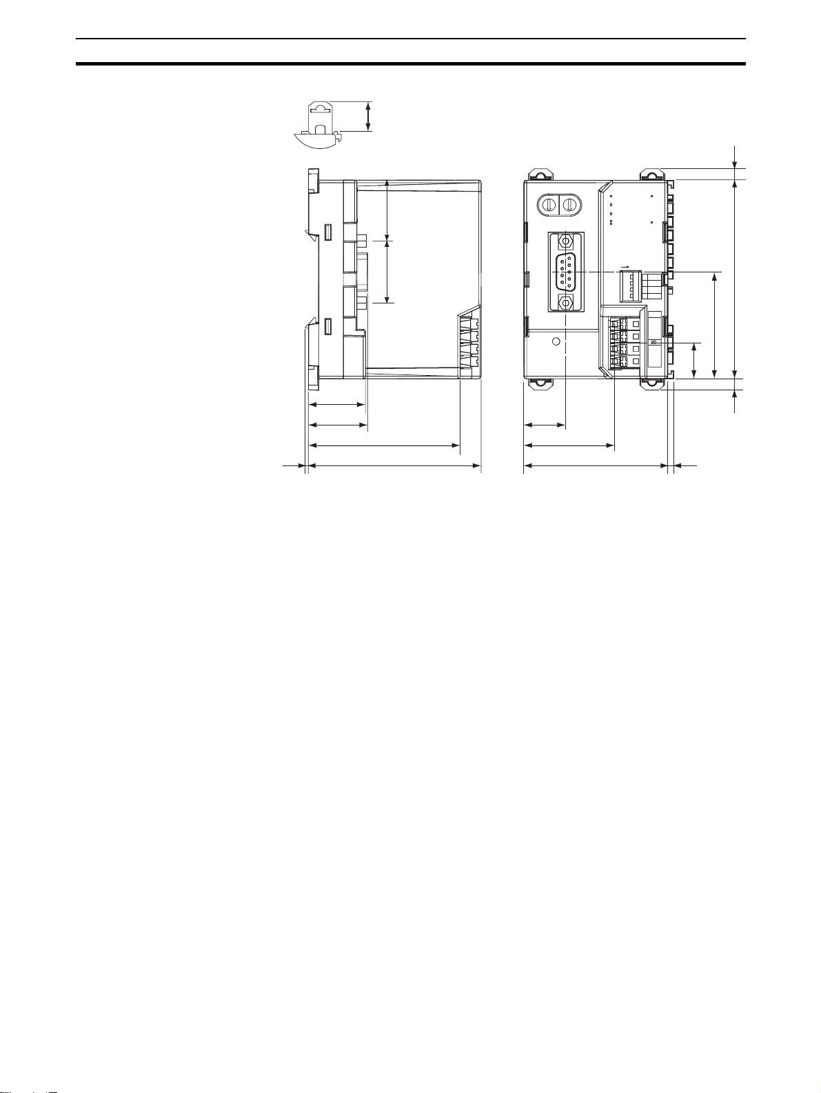
External Dimensions (mm)
11.9
2525
OMRON
GRT1-PRT
5
6
4
3
2
1
0
Section 1-3
2.9
RUN
5
6
4
7
7
3
8
8
2
9
9
1
0
X10
UNIT PWR
ERR
BF
TS
I/O PWR
23.1
24.4
61.2
1.5
69.7
1-3 GRT1-PRT Configuration
PROFIBUS Configuration
Means
The PROFIBUS DP Master Unit requires a configuration before it can
exchange I/O data with any of its slave devices. For this configuration information on the slave device must be available. OMRON provides two means
to facilitate Master Unit configuration.
•A GRT1-PRT DTM
• A GRT1-PRT GSD file
BUS
17.1
36.8
58
ON
REGS
1
NC
2
ADR
3
BACK
4
UNIT
+V
-V
+V
-V
DC24V
INPUT
83.5
43.7
16.2
2.9
2.4
GRT1-PRT Configuration
DTM
The GRT1-PRT DTM is an executable component, provided by OMRON,
which requires an FDT Container program like OMRON’s Cx-Profibus (refer
also to Appendix A-9 FDT/DTM Technology). The DTM runs inside this FDT
Container and provides its own User Interfaces. It can access GRT1-PRT and
SmartSlice I/O Unit data through the PROFIBUS Master unit and present that
to the user. It can also save the settings, using the features of the FDT Container program.
The GRT1-PRT DTM, provides the user with the following features.
• Parameter configuration
• I/O Configuration
• Configuration of individual SmartSlice I/O Units
• Monitoring of the SmartSlice I/O System
Note In order to configure individual SmartSlice I/O Units, the PROFIBUS Master
Unit must support PROFIBUS DP-V1, Class 2 functionality. The OMRON
CS1/CJ1W-PRM21 PROFIBUS Master Units support this functionality as of
revision 3.
7
Page 27

GRT1-PRT Configuration
Section 1-3
GRT1-PRT Parameter
Configuration
GRT1-PRT I/O
Configuration
Monitoring the SmartSlice
I/O System
Configuration via GSD File The GSD file concept is the older, and consequently more widely used means
The PROFIBUS Parameter User Interface allows the user to set operational
parameters for the communication between the PROFIBUS Master and the
GRT1-PRT. The User Interface provides entries to set
• the device address (i.e. defining it for communication)
• the PROFIBUS group allocation for the GRT1-PRT.
• the FINS fragment length, used in acyclic communication.
• Specific PROFIBUS Master Unit behaviour with respect to this slave
device.
The I/O Configuration User Interface allows the user to define the configuration of SmartSlice I/O Units attached to the PROFIBUS Communication Unit.
It also allows the user to make parameter settings for individual SmartSlice
I/O Units.
The I/O Configuration is used by the PROFIBUS Master Unit when mapping
the I/O data of individual SmartSlice I/O Units on to the PLC memory areas. It
is also sent by the PROFIBUS Master Unit to the GRT1-PRT for verification
when establishing communication. The I/O Configuration sent by the Master
Unit must match the physical configuration attached to the GRT1-PRT
PROFIBUS Communication Unit, in order to proceed with I/O data exchange.
The Monitoring User Interfaces allows the user to read information from individual SmartSlice I/O Units. It also provides a means to read the Error Log of
the GRT1-PRT PROFIBUS Communication Unit.
of configuration. The GSD file for the GRT1-PRT is a text based file, which
contains all options required to configure a PROFIBUS Master Unit. The file
can be loaded by the configuration software of the Master Units, which will
then present the information to the user to allow the appropriate selections to
be made.
The drawback of the GSD file is that- unlike the GRT1-PRT DTM - it only provides setting options for PROFIBUS DP and PROFIBUS DP-V1. The GSD file
does not provide the means to initiate parameter data transfer via PROFIBUS
DP-V1 Class 2 messages. These have to be programmed in the Master Unit it
self.
Third-Party Master Units The GSD file for GRT1-PRT can be used to configure most third-party Master
Units. The GRT1-PRT GSD file contains all the necessary parameters to
allow the user to configure the Master Unit for I/O data exchange.
Note 1. The GRT1-PRT DTM can also be used in third-party configuration soft-
ware provided that this software supports the FDT/DTM concept.
2. With the Cx-Profibus FDT Container OMRON also provides a Generic
Slave DTM, an FDT/DTM interface between the FDT Container program
and GSD files. Alternatively, this DTM can be used to setup a Master Unit,
using the GRT1-PRT GSD file. This Generic Slave DTM however, does
not provide the means to initiate PROFIBUS DP-V1 messages.
Downloading the
Configuration
After setting up the configuration, it must be downloaded to the PROFIBUS
Master Unit. The download process depends on the Master Unit used.
8
Page 28

Basic Operating Procedure
1-4 Basic Operating Procedure
1-4-1 Overview
The following diagram provides an overview of the installation procedures.
For experienced installation engineers, this may provide sufficient information. For others, cross-references are made to various sections of this manual
where more explicit information is given.
Mount the GRT1-PRT PROFIBUS Unit and
the SmartSlice I/O Units
(See section 2-2 Installing the GRT1-PRT
Unit)
Wire the GRT1-PRT PROFIBUS Unit and the
SmartSlice I/O Units
(See section 2-3 Wiring the GRT1-PRT)
Setup the PROFIBUS network
(See section 2-4 Setting up a PROFIBUS
Network)
Section 1-4
Power up the GRT1-PRT and Perform initial
setup (See section 3-3 Setup the GRT1-PRT
Configuration)
Configure the PROFIBUS DP Master Unit
(See section 3-3 Setup the GRT1-PRT
Configuration)
PROFIBUS DP starts communicating,
confirmed by the COMM LED continuously
lit. Check status of other LED Indicators (See
section 3-4 Operating the Network)
9
Page 29

Basic Operating Procedure
1-4-2 Preparations for Use
The following procedure shows the basic steps required before using the
PROFIBUS Communication Unit and the SmartSlice I/O Units.
Initial Setup Procedure
1,2,3... 1. Mount the GRT1-PRT Unit and the SmartSlice I/O system on the DIN rail
The maximum number of SmartSlice I/O Units can be 64.
2. Wire the SmartSlice I/O Units and the GRT1-PRT Unit’s power supply.
3. Wire the PROFIBUS network, to connect the Unit to the PROFIBUS Master Unit.
4. Set the rotary switches on the front of the GRT1-PRT to the desired
PROFIBUS address.
5. Turn ON the power to the Unit and the I/O.
6. Turn ON (from OFF to ON) DIP switch 1 on the front of the PROFIBUS
Communication Unit. When switch 1 is turned ON, the existing SmartSlice
I/O Unit configuration (connection order and I/O size) is registered in the
PROFIBUS Communication Unit as a registered table. After the table is
registered, leave pin 1 ON to enable the table.
Note The next time the power is turned ON, the actual SmartSlice I/O Unit configu-
ration at power on is automatically compared to the registered table. Any
SmartSlice I/O Units that do not match the registered table (connection order
or I/O size) will not participate in I/O communication. I/O communication will
start with the other SmartSlice I/O Units.
Section 1-4
Configuration Procedure Use the following procedure to configure the PROFIBUS Master Unit for com-
munication with the PROFIBUS Communication Unit, using the Cx-Profibus
FDT Container program and the GRT1-PRT DTM:
1,2,3... 1. In Cx-Profibus, create a network and define the parameters and I/O con-
figurations for the PROFIBUS Master Unit settings and the allocated slave
devices. Determine the baud rate and the bus parameter setup. Make sure
that the “Go to OPERATE mode “option is selected, to force the Unit to OPERATE mode upon a PLC mode change to RUN / MONITOR mode.
2. Download the network configuration to the PROFIBUS Master Unit. After
downloading the configuration, Cx-Profibus will restart the PROFIBUS DP
Master Unit.
3. After restarting the PROFIBUS DP Master Unit it will automatically start
communication.
10
Page 30

SECTION 2
Installation and Wiring
This section shows the GRT1-series PROFIBUS Communication Unit and identifies its controls and indicators. It contains
the procedures for installing and wiring the Communication Unit as well as the GRT1-series SmartSlice I/O Units. It also
contains the procedures for setting up the PROFIBUS network.
2-1 Unit Components . . . . . . . . . . . . . . . . . . . . . . . . . . . . . . . . . . . . . . . . . . . . . . 12
2-1-1 Nomenclature . . . . . . . . . . . . . . . . . . . . . . . . . . . . . . . . . . . . . . . . . . 12
2-1-2 LED Indicators . . . . . . . . . . . . . . . . . . . . . . . . . . . . . . . . . . . . . . . . . 12
2-1-3 Switch Settings . . . . . . . . . . . . . . . . . . . . . . . . . . . . . . . . . . . . . . . . . 13
2-1-4 Power Supply Connector . . . . . . . . . . . . . . . . . . . . . . . . . . . . . . . . . 15
2-1-5 PROFIBUS Connector . . . . . . . . . . . . . . . . . . . . . . . . . . . . . . . . . . . 15
2-2 Installing the GRT1-PRT Unit . . . . . . . . . . . . . . . . . . . . . . . . . . . . . . . . . . . . 16
2-2-1 Handling Precautions . . . . . . . . . . . . . . . . . . . . . . . . . . . . . . . . . . . . 16
2-2-2 Installation on a DIN Rail. . . . . . . . . . . . . . . . . . . . . . . . . . . . . . . . . 16
2-2-3 Connecting the PROFIBUS Unit and SmartSlice I/O Units. . . . . . . 18
2-2-4 Connecting Additional SmartSlice I/O Units . . . . . . . . . . . . . . . . . . 18
2-3 Wiring the GRT1-PRT . . . . . . . . . . . . . . . . . . . . . . . . . . . . . . . . . . . . . . . . . . 20
2-3-1 Connecting the SmartSlice I/O System Power Supply. . . . . . . . . . . 20
2-3-2 Wiring Methods . . . . . . . . . . . . . . . . . . . . . . . . . . . . . . . . . . . . . . . . 21
2-3-3 Connecting the Turnback Units . . . . . . . . . . . . . . . . . . . . . . . . . . . . 23
2-4 Setting up a PROFIBUS Network. . . . . . . . . . . . . . . . . . . . . . . . . . . . . . . . . . 24
2-4-1 Network Structure. . . . . . . . . . . . . . . . . . . . . . . . . . . . . . . . . . . . . . . 24
2-4-2 Bus Termination . . . . . . . . . . . . . . . . . . . . . . . . . . . . . . . . . . . . . . . . 26
2-4-3 PROFIBUS Cable Connector . . . . . . . . . . . . . . . . . . . . . . . . . . . . . . 27
2-4-4 Shielding Precautions . . . . . . . . . . . . . . . . . . . . . . . . . . . . . . . . . . . . 27
2-5 Installation of Configuration Software . . . . . . . . . . . . . . . . . . . . . . . . . . . . . . 28
2-5-1 Installation Requirements . . . . . . . . . . . . . . . . . . . . . . . . . . . . . . . . . 28
2-5-2 Installation Procedure . . . . . . . . . . . . . . . . . . . . . . . . . . . . . . . . . . . . 28
2-5-3 GRT1-PRT GSD File . . . . . . . . . . . . . . . . . . . . . . . . . . . . . . . . . . . . 29
11
Page 31

Unit Components
x10x1x1
BUS
ON
+V
+V
-V
UNIT
DC24V
INPUT
REGS
NC
ADR
BACK
RUN
ERR
BF
TS
UNIT PWR
I/O PWR
RUN
ERR
BF
TS
UNIT PWR
I/O PWR
2-1 Unit Components
2-1-1 Nomenclature
The illustration below shows the Status LED indicators, the PROFIBUS
address switches, and a 9-pin female sub-D connector on the front side of the
PROFIBUS Communication Unit. Each of these components are explained in
the following sections.
PROFIBUS communications connector
Connect the PROFIBUS network's
communications cable to this connector.
Rotary switches
Set the Unit's address as a PROFIBUS
Slave. Set a decimal node address between
0 and 99.
OMRON
GRT1-PRT
5
5
6
6
4
4
7
7
3
3
8
8
2
2
9
9
1
1
0
0
x10
BUS
Section 2-1
RUN
UNIT PWR
ERR
BF
TS
I/O PWR
ON
REGS
1
NC
2
ADR
3
BACK
4
UNIT
+V
-V
+V
-V
DC24V
INPUT
Indicators
Refer to 2-1-1 LED Indicators for details.
DIP Switch
Sets the I/O allocation method and registers the I/O Unit
configuration information.
SW1 (REGS): Create/enable registration table.
SW2 (NC): Not used, set to OFF
SW3 (ADR): Automatic restore
SW4 (BACK): Backup trigger
Unit power supply terminals
Connect the power supply for the Unit's internal circuits
and the connected SmartSlice I/O Units' internal circuits.
I/O power supply terminals
Connect the power supply for the connected
SmartSlice I/O Units' external I/O.
2-1-2 LED Indicators
Indicator Specifications
Indicator Colour Status Meaning
RUN
Unit status
ERR
Unit error
12
Green Not lit • Startup test failed, Unit not operational.
Red Not lit Unit is in normal operation.
The GRT1-PRT PROFIBUS Communication Unit is fitted with six LED indicators to indicate the operational mode and status of the Unit and the PROFIBUS network.
RUN
UNIT PWR
ERR
BF
TS
I/O PWR
• Operation stopped, due to a fatal error.
Lit Initialization successful, Unit is in normal operation.
Flashing A startup error has occurred
Lit • Fatal error in program execution.
• Error Log Read or Write occurred.
Page 32

Unit Components
x10x1x1
Section 2-1
Indicator Colour Status Meaning
BF
PROFIBUS Failure
Red Not lit No PROFIBUS communication errors occurred. I/O Data Exchange is
in progress.
Flashing The parameter settings sent by the PROFIBUS Master unit are invalid.
No I/O Data Exchange is possible.
Lit No PROFIBUS communication has been detected by the Unit.
TS
SmartSlice I/O System
communication status
-- Not Lit • Power not being supplied.
• Communication has not started with SmartSlice I/O Unit.
• Over current detected.
Green Flashing SmartSlice I/O Unit added to the system (Flashing once every 1 s)
Backup/Restore function operating (Flashing once every 0.5 s)
• Restoring settings to SmartSlice I/O Unit, backup function operating.
• Downloading SmartSlice I/O Unit settings.
Lit Communication with SmartSlice I/O Unit established.
Red Flashing Non-fatal communication error occurred.
• Communication timeout
• Verification error occurred with registered table.
• Different model Unit detected after I/O Unit replacement.
Lit Fatal communication error occurred.
Failure occurred while restoring settings to I/O Unit or downloading I/O
Unit settings (Lit for 2 s)
UNIT PWR Green Not Lit Power supply to the Unit is not present (All other LED indicators are
also OFF).
Lit Power supply to the Unit is present.
I/O PWR Green Not Lit Power supply to the SmartSlice I/O is not present. The SmartSlice I/O
Units may be operative, but no output is available.
Lit Power supply to the SmartSlice I/O is present.
2-1-3 Switch Settings
Rotary Switches Two rotary switches on the front of the GRT1-PRT, marked x10 and x1, are
provided to set the PROFIBUS device address of the Unit. The address can
5
5
6
7
8
9
x10
6
4
7
3
8
2
9
1
0
4
3
2
1
0
1,2,3... 1. Turn OFF the power supply before setting the device address.
Note 1. Always turn OFF the power to the Unit before changing the device address
be set in the range of 00 through 99 (decimal). The device address on the Unit
must be the same as the address used in the master’s configuration. The
device address is used to uniquely identify PROFIBUS Communication Unit
on the PROFIBUS DP network. Selecting a non-unique address for the unit
will prevent the unit from communicating properly with the Master unit.
In order to set the device address, perform the following steps.
2. Set the switch to the (new) device address. Use a small screwdriver to
make the setting, taking care not to damage the rotary switch. The station
address is factory-set to 0.
3. Turn ON the power again.
setting. The Unit only reads the address setting during the initialization following a power-up, i.e. any changes after power up will have no effect.
2. The PROFIBUS Communication Unit detects the Master’s communication
baud rate automatically. Setting the baud rate is not required.
13
Page 33

Unit Components
Section 2-1
DIP Switches Four DIP switches on the front of the Unit are provided for operational set-
tings. The factory setting is OFF for all DIP switches.
ON
1
2
3
4
REGS
NC
ADR
BACK
DIP switch Caption Description
1 REGS Create / Enable Registration Table.
2 NC Not Used (Always OFF).
3 ADR Automatic Restore.
4 BACK Backup Trigger.
DIP Switch 1: REGS
Create / Enable
Registration Table
DIP Switch 2: NC
Not Used
DIP Switch 3: ADR
Automatic Restore
If DIP switch 1 is turned from OFF to ON while the Unit’s power is ON, the
existing SmartSlice I/O Unit configuration (connection order and I/O size) is
registered in the PROFIBUS Communication Unit as a registered table.
If DIP switch 1 is ON when the Unit’s power is turned ON, the actual SmartSlice I/O Unit configuration at startup is automatically compared to the registered table. Any SmartSlice I/O Units that do not match the registered table
will not participate in SmartSlice I/O communication.
Switch setting Function
ON Registered table is enabled. (If there is a verification error, the
OFF Registered table is disabled (All Units participate in communica-
OFF to ON Register I/O Unit table (Unit Power must be ON)
ON to OFF Clear registered I/O Unit table (Unit Power must be ON)
affected Unit will not participate in communication.)
tion).
DIP switch 2, marked NC is not used and should always be set to OFF.
When DIP switch 1 is ON (registered table enabled) and DIP switch 3 is
switched to ON, parameter data is automatically restored to the SmartSlice
I/O Units that had parameter data backed up.
Switch setting Function
ON
OFF Automatic restore function disabled.
Switch OFF to ON to start the parameter restore (when
1 is ON).
switch
DIP
DIP Switch 4: BACK
Backup Trigger
14
When DIP switch 1 is ON (registered table enabled) and DIP switch 4 is
turned OFF to ON, the parameter data of all connected SmartSlice I/O Units is
backed up in the Communication Unit.
1 s 1 s 1 s
ON OFF ON
The backup operation starts after DIP switch 4 is
turned from ON to OFF to ON within 3 seconds.
Switch setting Function
ON
OFF ---
Switch ON to OFF to ON to start the parameter backup (when
1 is ON).
switch
Note It is recommended to leave DIP switches 1, 3 and 4 always ON.
DIP
Page 34

Unit Components
2-1-4 Power Supply Connector
The PROFIBUS Communication Unit provides two 24VDC power supply terminals on the front of the Unit.
Section 2-1
System Power supply terminals
External I/O Power supply terminals
Power supply
terminals
Unit power supply terminals
I/O power supply
terminals
Note System Power supply and External I/O power supply are not transferred
through the GCN2-100 Turnback cable. The GRT1-TBR units provide the
same set of Power supply terminals as the PROFIBUS Communication Unit.
2-1-5 PROFIBUS Connector
The PROFIBUS connector on the font of the Unit is a 9-pin female sub-D connector, as recommended by the PROFIBUS standard EN50170.
Holes for wires
(pin terminals)
24 VDC
24 VDC
These terminals supply power to the PROFIBUS Communication
Unit’s internal circuits as well as the connected SmartSlice I/O
Units’ internal circuits (supplied through the SmartSlice bus).
These terminals supply power to the external I/O that is connected to the System’s SmartSlice I/O Units.
Release button
Description
Pin No. Signal Description
9
6
5
1
1 Shield Shield/protective ground
2--
3 B-line Receive/Transmit data - plus (B wire)
4 RTS Control signal for repeaters (direction control) (TTL)
5 DGND Data ground (reference potential for VP)
6 VP Supply voltage of the terminator resistance (5 Vdc)
7--
8 A-line Receive/Transmit data - minus (A wire)
9--
The signal RTS (TTL signal) is for the direction control of repeaters, which do
not have a self-controlling capability.
The signals DGND and VP are used to power the bus terminator located in
the cable connector.
Note 1. The orientation of the sub-D connector allows the use of PROFIBUS con-
nectors with a 90° angle cable outlet, e.g ERNI, Delconec and Phoenix.
2. The 9-pin sub-D connector uses #4/40 UNC thread for mechanical fixation
of the cable connector. Make sure that if non-standard PROFIBUS connectors are used, the same thread is used on the cable connector.
3. PROFIBUS DP Baud rate setting is accomplished through automatic detection, all the defined PROFIBUS DP baud rate values are supported.
15
Page 35

Installing the GRT1-PRT Unit
x10x1x1
BUS
ON
+V
-V
DC24V
INPUT
REGS
NC
ADR
BACK
RUN
ERR
BF
TS
UNIT PWR
I/O PWR
2-2 Installing the GRT1-PRT Unit
2-2-1 Handling Precautions
When installing the PROFIBUS Communication Unit and the SmartSlice I/O
Units, observe the following handling precautions
• Always turn OFF the power supply to the PROFIBUS Communication
Unit, the SmartSlice I/O Units and the external I/O, before mounting or
dismounting a Unit or connecting or disconnecting cables.
• Do not connect or disconnect the PROFIBUS Communication Unit’s communication cable while the PROFIBUS network is operating. Short-circuits or poor contacts in the PROFIBUS cable may prevent normal
communication.
• Ensure that the power supplies for the PROFIBUS Communication Unit
and the SmartSlice I/O Units and the external I/O are wired correctly.
• Provide separate conduits or ducts for the I/O lines to prevent noise from
high-tension lines or power lines.
The SmartSlice I/O system is installed and set up as a PROFIBUS DP-V1
Slave. The PROFIBUS Communication Unit’s communication connector connects to the Master Unit through a PROFIBUS communication cable. Up to 64
SmartSlice I/O Units can be connected to one GRT1-PRT Unit.
Section 2-2
PROFIBUS
Master
PROFIBUS
Communication Unit
OMRON GRT1-PRT
5
5
RUN
UNIT PWR
6
6
4
4
7
7
3
3
8
8
ERR
2
2
9
9
1
1
0
0
BF
x10
TS
I/O PWR
BUS
24 VDC
for Unit
24 VDC
for I/O
ON
REGS
1
NC
2
ADR
3
BACK
4
+V
-V
DC24V
INPUT
Slide SmartSlice I/O Units
in from the front to install.
SmartSlice I/O Units (64 max.)
2-2-2 Installation on a DIN Rail
DIN Rail Installation The GRT1-PRT and SmartSlice I/O Units must be mounted on a DIN Rail.
Attach the DIN Rail with screws in every fourth mounting hole.
PFP-50N (50 cm) or PFP100N (100 cm) DIN Rail
16
Attach the track with screws at a
maximum spacing of 105 mm
between adjacent screws.
Page 36

Installing the GRT1-PRT Unit
a
c
o
Section 2-2
SmartSlice I/O System
Orientation
There is no restriction regarding orientation of the SmartSlice I/O System. The
system can be mounted in any of the following 6 directions.
Installing a Unit To install a PROFIBUS Communication Unit on the DIN Rail, press the Unit
onto the DIN Track from the front. Press the Unit firmly until it clicks, indicating
that the Unit’s DIN Rail Mounting Hooks have all locked onto the DIN Rail.
When the Unit is pushed onto the DIN Rail,
verify that the Mounting Hooks have locked.
Mounting Hooks
Press firmly towards the DIN R
Press firmly until you hear a cli
indicating that the Mounting Ho
have locked.
Removing a Unit Use a standard screwdriver to release the DIN Rail Mounting Hooks at the top
and bottom of the Unit and pull the Unit straight away from the DIN Rail.
17
Page 37

Installing the GRT1-PRT Unit
k
k
g
2-2-3 Connecting the PROFIBUS Unit and SmartSlice I/O Units
Connect the first SmartSlice I/O Unit to the PROFIBUS Communication Unit
by aligning the sides of the Units and sliding in the SmartSlice I/O Unit from
the front. Additional SmartSlice I/O Units can be connected consecutively to
the first.
Slide the Slice I/O Unit toward the DIN Track from
the front. Insert the Unit until you hear a click,
which indicates that the Unit has locked on the Trac
It is normally not necessary to release the DIN Trac
mounting hook when mounting the Unit.
Note Do not touch the connector on the Unit’s base block.
Section 2-2
2-2-4 Connecting Additional SmartSlice I/O Units
Connect additional SmartSlice I/O Units by aligning the sides of the Units and
sliding in the next Unit from the front. Up to 64 SmartSlice I/O Units can be
connected to one PROFIBUS Communication Unit.
Slide the Unit to the DIN Track from the front.
Insert the Unit until you hear a click, which indicates
that the Unit has locked on the Track.
It is normally not necessary to release the DIN Track
mountin
hook when mounting the Unit.
Connecting Turnback
Units
18
When a SmartSlice I/O System is divided into blocks, connect a GRT1-TBR
Right Turnback Unit to the right end of the first block. Connect a GRT1-TBL
Left Turnback Unit to the left side of the expansion block and connect additional SmartSlice I/O Units. Use a GCN2-100 Turnback Cable to connect the
Turnback Units together.
Page 38

Installing the GRT1-PRT Unit
(
)
(
)
x10x1x1
BUS
ON
+V
+V
-V
DC24V
INPUT
REGS
NC
ADR
BACK
RUN
ERR
BF
TS
UNIT PWR
I/O PWR
Section 2-2
Turnback Cable connectors
Note The Turnback Units can be used to divide a SmartSlice I/O System into up to
Connecting the End
Unit
Installing the End
Plates
GRT1-TBR Turnback Unit
for right side of block
GRT1-TBL Turnback Unit
for left side of block
three blocks.
A GRT1-END End Unit must be connected at the end of the SmartSlice I/O
System.
GRT1-END End Unit
Always secure the SmartSlice I/O System on the DIN Rail by installing End
Plates on both sides of the System. First hook the bottom of the End Plate on
the bottom edge of the DIN Rail (1), attach the top of the End Plate, and pull
the End Plate down onto the top edge of the DIN Rail (2). Tighten the End
Plate’s securing screw.
End Plate
OMRON GRT1-PRT
5
6
4
7
3
8
2
9
1
0
x10
BUS
RUN
UNIT PWR
5
6
4
7
3
8
ERR
2
9
1
0
BF
TS
I/O PWR
ON
REGS
1
NC
2
ADR
3
BACK
4
+V
-V
+V
-V
DC24V
INPUT
End Unit
2
1
End Plate
Note Always secure the SmartSlice I/O System by attaching End Plates on both
ends.
19
Page 39

Wiring the GRT1-PRT
Section 2-3
2-3 Wiring the GRT1-PRT
2-3-1 Connecting the SmartSlice I/O System Power Supply
The PROFIBUS Communication Unit has two sets of power supply terminals
for the following two systems.
Power supply
terminals
Unit power supply
terminals
I/O power supply terminals
Both the SmartSlice I/O System power supply and the external I/O power supply are connected with screwless clamping-type terminals.
These terminals supply power to the PROFIBUS Communication Unit’s internal circuits as well as the connected SmartSlice I/O Units’ internal circuits (supplied through the
SmartSlice bus).
These terminals supply power to the external I/O that is connected to the System’s SmartSlice I/O Units.
Evaluating the Power
Supply Requirements
Unit Power Supply The maximum power consumption for SmartSlice I/O Units is 80 W per block.
Description
1,2,3... 1. Calculate the power consumption of all of the SmartSlice I/O Units con-
nected to the PROFIBUS Communication Unit. Refer to the GRT1 Series
SmartSlice I/O Units Operation Manual (W455) for the power value for
each SmartSlice I/O Unit.
2. If the power consumption exceeds 80 W, mount a Right Turnback Unit
(GRT1-TBR) on the SmartSlice I/O Unit at the point where the power consumption is less than 80 W.
3. Connect the 24 VDC Unit power supply to the Left Turnback Unit (GRT1TBL).
Note 1. The GRT1-TBL is equipped with separate power supply terminals for the
Unit power supply and I/O power supply.
2. When dividing the power supply, always wire (supply) the power from the
same power supply (Refer to the Wiring Example).
I/O Power Supply The maximum I/O current consumption is 4 A.
1,2,3... 1. Calculate the total current consumption used by all external I/O of the con-
nected SmartSlice I/O Units (including other Units like Turnback Units).
Refer to the GRT1 Series SmartSlice I/O Units Operation Manual (W455)
for the current value for each SmartSlice I/O Unit.
2. If the current consumption exceeds 4 A or you want to provide separate
systems for inputs and outputs, divide the SmartSlice I/O Units at the desired point with a GRT1-PD2 I/O Power Supply Unit and provide a separate external I/O power supply.
3. It is also possible to provide a separate external I/O power supply at a Left
Turnback Unit (GRT1-TBL).
20
Note 1. The GRT1-TBL is equipped with separate power supply terminals for the
Unit power supply and I/O power supply.
2. Always use isolated power supplies for the power supplies.
3. Power is not supplied through the GCN2-100 Turnback Cable.
(Refer to the Wiring Example.)
Page 40

Wiring the GRT1-PRT
Wiring Example
Section 2-3
I/O
power
supply
I/O
(IN)
I/O
(AD)
PROFIBUS
Communication Unit
CPU
Connector
Power supply
(24 VDC)
I/O
power
supply
GRT1-TBL Turnback Unit (Left)
2-3-2 Wiring Methods
Supplying Power to
the Units
Connect the power supply wires (24 VDC) to the PROFIBUS Communication
Unit’s screwless clamping power supply terminals. If pin terminals are used
on the wire ends, the pin terminals can just be inserted to wire the power.
GRT1-PD2 I/O Power Supply Unit
I/O
(IN)
I/O
(AD)
I/O
(OUT)
I/O
power
supply
I/O
I/O
(AD)
(AD)
(OUT)
I/O
(AD)
I/O
I/O
(OUT)
End Unit
GRT1-TBR Turnback Unit (Right)
I/O
I/O
(OUT)
Connector
(OUT)
Power is not supplied through
the Turnback Cable.
Do not exceed 80 W
power consumption
in one block.
Do not exceed 80 W
power consumption
in one block.
Holes for wires
(pin terminals)
Press the release button with
a screwdriver and pull out the
wire (pin terminal).
Release button
These terminals supply power to both
the PROFIBUS Communication Unit's
24 VDC
internal circuits and the connected
SmartSlice I/O Units' internal circuits.
Note The GRT1-TBL Left Turnback Unit has the same screwless clamping power
supply terminals as the PROFIBUS Communication Unit. These terminals are
wired in the same way, by inserting the power supply wires.
21
Page 41

Wiring the GRT1-PRT
Section 2-3
Supplying I/O Power The power supply for I/O devices is supplied through the PROFIBUS Commu-
nication Unit’s screwless clamping power supply terminals. If pin terminals are
used on the wire ends, the pin terminals can be inserted to wire the power.
Holes for wires
(pin terminals)
These terminals supply power to the
external I/O devices connected to the
SmartSlice I/O Units.
Release button
Press the release button with
a screwdriver and pull out the
wire (pin terminal).
24 VDC
Note The GRT1-TBL Left Turnback Unit and GRT1-PD2 I/O Power Supply Unit
have the same screwless clamping power supply terminals. These terminals
are wired in the same way as the PROFIBUS Communication Unit’s terminals, by inserting the power supply wires.
Removing Wires To remove the wires press the release button above the terminal hole using a
slotted precision screwdriver and pull out the wire.
Slotted precision screwdriver
Side view Front view
3.5 mm0.6 mm
Recommended model: SZF1 (Phoenix Contact)
Recommended Power
Supplies
Recommended Wire
Strip Length
Pin Terminal Length
Release button
Use a SELV power supply with over current protection.
A SELV power supply has redundant or increased insulation between the I/O,
an output voltage of 30 Vr.m.s and a 42.4-V peak or maximum of 60 VDC.
Recommended power supply: S82K-01524 (OMRON) or S8TS-06024
(OMRON).
Type Gauge
Stranded wire 20 AWG to 16 AWG
Solid wire
Pin terminal
(0.5 to 1.25 mm
2
)
Strip wire between 7 and 10 mm of insulation at the ends of the wires
(stranded or solid wire) or use pin terminals with a pin (conductor) length of 8
to 10 mm.
Strip 7 to 10 mm.
Pin length: 8 to 10 mm
22
Page 42

Wiring the GRT1-PRT
x10x1x1
BUS
ON
+V
-V
UNIT
DC24V
INPUT
REGS
NC
ADR
BACK
RUN
ERR
BF
TS
UNIT PWR
I/O PWR
2-3-3 Connecting the Turnback Units
When a SmartSlice I/O System is divided into blocks to expand the system,
connect a GRT1-TBR Right Turnback Unit to the GRT1-TBL Left Turnback
Unit with a GCN2-100 Turnback Cable.
Note Power is not supplied through the GCN2-100 Turnback Cable. Always wire
(supply) the power to the GRT1-TBL Left Turnback Unit from the same power
supply that supplies the PROFIBUS Communication Unit.
Connect the Turnback Units with a Turnback Cable, as shown in the following
diagram. A single PROFIBUS Communication Unit can be expanded with up
to two additional blocks, connected with two Turnback Cables (2 m total).
OMRON GRT1-PRT
RUN
UNIT PWR
5
5
6
6
4
4
7
7
3
3
ERR
8
8
2
2
9
9
1
1
0
0
BF
TS
I/O PWR
x10
ON
BUS
REGS
1
NC
2
ADR
3
BACK
4
UNIT
+V
-V
DC24V
INPUT
Section 2-3
GRT1-TBR Turnback Unit
GCN2-100 Turnback Cable
GRT1-TBL Turnback Unit
Insert the cable's connector fully
until it clicks, which indicates that
the connector's top and bottom
latches have locked.
23
Page 43

Setting up a PROFIBUS Network
Section 2-4
2-4 Setting up a PROFIBUS Network
2-4-1 Network Structure
Communication Medium The PROFIBUS standard defines the use of EIA RS-485 as the main commu-
nication transport medium. The PROFIBUS DP Master Unit is designed to
interface directly to this type of medium. This section will discuss the setup of
networks based on this medium.
Note The other communication medium specified for PROFIBUS is optical fibre.
The PROFIBUS DP Master Units does not provide a direct interface to this
type of medium. However, by using third party couplers an interface between
EIA RS-485 and optical fibre networks can be made.
Linear Bus Topology PROFIBUS DP defines the use of the Linear Bus Network Topology. The Bus
must be terminated at both ends, and must not contain network branches.
The total cable length of the bus depends on the cable and the selected baud
rate. Also, RS-485 specifies a maximum of up to 32 devices - master and
slave devices - per line segment. If more than 32 devices are to be connected, or if the total length of the segment must be extended beyond its maximum, repeaters must be used to link the separate segments.
Note Repeaters are devices which connect two segments. They do not have a
device address of their own, but they do count in the total number of devices
in a segment.
Repeaters A maximum of up to three repeaters between two devices in a network can be
used, i.e. a network can consist of up to 4 segments. The maximum number
of PROFIBUS devices in such a network is then 122. The figure below shows
an example of a two-segment network.
OMRON
SYSMAC CS1G
PROGRAMMABLE
CONTROLLER
Termination
Station 1
Termination
Termination
Repeater
Station 2 Station 3 Station 31
Station 63 Station 33 Station 32
Termination
Tree Topology The use of repeaters allows the extension of three or more Linear Bus seg-
ments into a Tree topology. In a tree topology more than three repeaters are
allowed, provided that there are no more than three repeaters between any
two devices in the network. The following figure presents an example of a network with more than three segments and repeaters.
24
Page 44

Setting up a PROFIBUS Network
Section 2-4
Segment 1
Max. 31 stations
M / S
R
Segment 4
Max. 31 stations
M / S
M / S
Master or slave station
R
Repeater
Termination
Max. total number of stations = 126
R
Segment 3
Max. 28 stations
Segment 5
Max. 30 stations
Segment 2
Max. 31 stations
R
R
M / S
R
Segment 6
Max. 31 stations
M / S
M / S
M / S
Cable Type The PROFIBUS standard EN 50170 specifies Type A shielded, twisted- pair
cable as the recommended cable type for use in an RS-485 based PROFIBUS network. This cable type has the following characteristics:
Maximum PROFIBUS
Cable Length
Characteristic Value
Impedance 135 - 165 ohms
Capacitance per unit length < 30 pF/m
Loop resistance 110 ohms/km
Core diameter 0.64 mm
Core cross section
0.34 mm
2
Note The PROFIBUS standard EN 50170 also specifies a Type B cable with differ-
ent cable characteristics. Use of Type B cable is no longer recommended.
The transmission speed defines the maximum advised cable distance or
cable segment in metres before the use of a repeater is recommended. The
cable lengths specified in the following table are based on PROFIBUS type A
cable.
Baud rate
(kbit/s)
9.6 1200 500 400
19.2 1200 1500 200
45.45 1200 3000 100
93.75 1200 6000 100
187.5 1000 12000 100
Distance/segment
(m)
Baud rate
(kbit/s)
Distance/segment
(m)
Note If network extension beyond the range of the advised cable length is required,
the use of fibre optic cable to cross the larger distance should be considered.
Stub Lines Passive Stub lines (branches from the main line) should be avoided for data
transmission speeds of more than 500 kbit/s. Except at end devices with termination, it is recommended to always use plug connectors that permit two
25
Page 45

Setting up a PROFIBUS Network
k
Section 2-4
data cables to be connected directly to the plug. This method allows the bus
connector to be plugged and unplugged at all times without interrupting data
communication between other devices.
2-4-2 Bus Termination
Termination Resistors In order to minimize cable reflections and ensure a defined signal level on the
data lines, the data transfer cable must be terminated at both ends with a terminating resistor combination. The bus termination diagram is shown on the
left.
The bus terminator connects the two data lines via a 220 ohm resistor which,
in turn, is connected to VP 5Vdc and DGND via two 390 ohm resistors. Powering the terminator resistor via VP 5V and DGND ensures a defined idle state
potential on the data lines.
To ensure the correct functioning up to the highest baud rate, the bus cable
must be terminated at both its ends.
A missing bus termination can cause errors during data transfer. Problems
can also arise if too many bus terminators are fitted, since each bus terminator represents an electrical load and reduces the signal levels and thus the
signal-to-noise ratio. Too many or missing bus terminators can also cause
intermittent data transfer errors, particularly if the bus segment is operated
close to the specified limits for maximum numbers of devices, maximum bus
segment length and maximum data transfer rate.
B-Line
A-Line
DGND
VP
390 Ohm
220 Ohm
390 Ohm
Networ
Inductors In addition to the bus termination, additional precautions must be taken to
ensure proper operation at high baud rates, i.e. baud rates of 500 kbit/s and
higher. Due to the capacitive load of the device and the resulting cable reflec-
B-Line
A-Line
110 mH
Network
110 mH
tions, bus connectors must be provided with built-in series inductors, of 110
mH each, as shown in the figure on the left.
Installing the inductors applies to all devices on the network, and not only to
the devices at both ends of the bus cable.
26
Page 46

Setting up a PROFIBUS Network
Section 2-4
2-4-3 PROFIBUS Cable Connector
Bus Cable Connector The plug connector to be used on the CS/CJ-series PROFIBUS DP Master
Unit is a 9-pin male sub-D type, preferably encased in metal and having a
facility to connect the shield of the cable to the case or to pin 1. The cable
should be connected to the receive / transmit lines, pin 3 (B-line) and pin 8 (Aline).
The use of special PROFIBUS DP cable connectors, which are available from
several manufacturers, is highly recommended. Various models are widely
available, with or without the bus termination and inductors built-in. If provided
in the connector, the Bus termination can often be enabled or disabled
through a switch on the connector.
The special PROFIBUS DP cable connectors often provide a convenient way
of connecting the cables. The figure on the left, provides an example of such
a bus cable connector.
A standard 9-pin sub-D plug can only be used if the PROFIBUS DP Master
Unit is not at the start or the end of a bus segment, or on a stub line at a baud
To next
station
From
previous
station
rate of 500 kbit/s or less.
The two PROFIBUS data lines are designated A and B. There are no regulations on which cable core colour should be connected to which of the two data
terminals on each PROFIBUS device; the sole requirement is to ensure that
the same core colour is connected to the same terminal (A or B) for all
devices throughout the entire system (across all devices and bus segments).
The PROFIBUS Organization recommends the following rule for data line
colour codes: PROFIBUS cables in general will use the colours red and green
for the data lines, with the following assignment:
• Data cable wire A - green
• Data cable wire B - red
This rule applies to both the incoming and the outgoing data lines.
2-4-4 Shielding Precautions
Cable Shield Connection To ensure electro-magnetic compatibility (EMC), the shield of the cable
should be connected to the metal case of the plug connector.
Inside cabinet
Ground Rail
Outside cabinet
If the Unit is installed in a control cabinet, the bus cable shield should be
brought into physical contact with a grounding rail using a grounding clamp or
similar device. The cable shield should continue in the cabinet right up to the
PROFIBUS device.
Ensure that the PLC and the control cabinet in which it is mounted have the
same ground potential by providing a large-area metallic contact to ground,
e.g. galvanized steel to ensure a good electrical connection. Grounding rails
should not be attached to painted surfaces.
For further information regarding PROFIBUS network installation, please refer
to “Installation Guideline for PROFIBUS DP/FMS” (PNO Order No. 2.112),
which is available at every regional PROFIBUS Organization. The information
covers:
• Commissioning of PROFIBUS equipment.
• Testing the PROFIBUS cable and bus connectors.
• Determining loop resistance.
• Testing for correct bus termination.
• Determining the segment length and cable route.
27
Page 47

Installation of Configuration Software
2-5 Installation of Configuration Software
In order to operate the GRT1-PRT and the SmartSlice I/O system the PROFIBUS DP Master needs to be configured for communication with the GRT1PRT. For this purpose OMRON provides the GRT1-PRT DTM via the
OMRON web site http://www.omron-industrial.com/
After installation the DTM will run in the OMRON Cx-Profibus FDT Container,
allowing the user to setup the I/O configuration and setting the parameters of
both the GRT1-PRT as well as individual SmartSlice I/O Units.
Note To fully utilize the features of the GRT1-PRT and the SmartSlice I/O system, a
PROFIBUS DP-V1 Class 2 capable Master Unit and DTM are required. The
OMRON CS1/CJ1W-PRM21 Master units provide this functionality as of version 3.0.
2-5-1 Installation Requirements
The following are the minimum requirements for a PC to install the GRT1PRT DTM configuration software:
• PC Pentium III or higher, 500 MHz minimum
• Operating System: Windows 2000 SP2 / Windows NT 4.0, SP6 /
Windows XP
• RAM: 256 MB minimum
• Hard disk space: 256 MB minimum
• Graphics resolution: 1024 x 768 pixels minimum
• Installed FDT Container software, e.g. OMRON’s Cx-Profibus.
Section 2-5
2-5-2 Installation Procedure
DTM Installation This section explains how to install the Cx-Profibus Configuration software
and its components for the PROFIBUS Master Unit.
1,2,3... 1. Exit all other Windows-based programs.
2. Double-click the file GRT1PRT_SmartSlice_IO_Coupler_Setup.exe.
The setup program for the GRT1-PRT DTM will start. A progress dialog
window is displayed, indicating progress of the setup as the program is
loaded.
3. The setup program will check the version of the CS1/CJ1W-PRM21
PROFIBUS Master DTM installed. Running the GRT1-PRT requires a
Master DTM version of 0.7.0.0. or higher. If this version is not installed, the
following warning screen will pop up.
The appropriate version of the CS1/CJ1W-PRM21 Master DTM is avail-
able through OMRON’s web site. Pressing the OK button, will continue
with installation.
28
Page 48

Installation of Configuration Software
4. The user is then prompted to specify the installation directory.
5. Pressing the Next button will summarize the settings after which installa-
tion will commence.
6. When done, the installation program will notify the user of its completion.
Section 2-5
Updating the Device
Catalogue
1,2,3... 1. Open the Device Catalogue window in Cx-Profibus.
After installation of the GRT1-PRT DTM the Device Catalogue in the FDT
Container needs to be updated, to show the new GRT1-PRT DTM in the list of
available devices. For Cx-Profibus the following procedure applies
2. Press the Update button to initiate the update sequence.
After updating, the GRT1-PRT DTM will be shown in the list of available
devices. It can now be used to setup a PROFIBUS network and configure the
Master Unit.
Note In case the required CS1/CJ1W-PRM21 PROFIBUS Master DTM has not
been installed, this needs to be done first to allow the full features of the
GRT1-PRT DTM to be used.
2-5-3 GRT1-PRT GSD File
Apart from the GRT1-PRT DTM, OMRON provides a GSD file to allow configuration of third-party PROFIBUS Master Units, which do not provide an FDT
Container. The GSD file - OC_09FE.gsd - is available through the OMRON
Web site: http://www.omron-industrial.com/
Section 3-3-3 Setup Using the GSD File discusses configuration of the
PROFIBUS DP Master using this GSD file.
Note Using the GSD file for configuration allows the user to configure the Master
Unit for I/O data exchange with the GRT1-PRT and the SmartSlice I/O System. It does not however, provide the acyclic messaging capabilities to
access parameters and status information in individual SmartSlice I/O Units.
The GRT1-PRT DTM does provide this capability.
The next section will discuss the features of the GRT1-PRT in detail as well
as how to setup, configure and operate the SmartSlice I/O System in a
PROFIBUS network.
29
Page 49

Page 50

SECTION 3
Setup and Operation
This section describes the operational aspects of the GRT1-PRT and the SmartSlice I/O System. It first discusses the
operational features which can be used, prior to describing how to setup the system and how to operate and monitor it on a
PROFIBUS network.
3-1 Station Address Settings and I/O Allocation . . . . . . . . . . . . . . . . . . . . . . . . . 32
3-1-1 Setting the PROFIBUS Station Address. . . . . . . . . . . . . . . . . . . . . . 32
3-1-2 SmartSlice I/O Unit Number Allocation . . . . . . . . . . . . . . . . . . . . . 32
3-1-3 SmartSlice I/O Allocation to the GRT1-PRT Unit . . . . . . . . . . . . . . 33
3-2 Unit Functions . . . . . . . . . . . . . . . . . . . . . . . . . . . . . . . . . . . . . . . . . . . . . . . . . 36
3-2-1 Table Registration Function . . . . . . . . . . . . . . . . . . . . . . . . . . . . . . . 36
3-2-2 Backup Function . . . . . . . . . . . . . . . . . . . . . . . . . . . . . . . . . . . . . . . . 38
3-2-3 Automatic Restore Function . . . . . . . . . . . . . . . . . . . . . . . . . . . . . . . 38
3-2-4 Online Replacement Function . . . . . . . . . . . . . . . . . . . . . . . . . . . . . 40
3-2-5 I/O Communication Error History Monitor . . . . . . . . . . . . . . . . . . . 41
3-3 Setup the GRT1-PRT Configuration . . . . . . . . . . . . . . . . . . . . . . . . . . . . . . . . 42
3-3-1 Defining the PROFIBUS Network . . . . . . . . . . . . . . . . . . . . . . . . . . 42
3-3-2 Setup Using the DTM . . . . . . . . . . . . . . . . . . . . . . . . . . . . . . . . . . . . 43
3-3-3 Setup Using the GSD File. . . . . . . . . . . . . . . . . . . . . . . . . . . . . . . . . 48
3-3-4 Mapping I/O Data . . . . . . . . . . . . . . . . . . . . . . . . . . . . . . . . . . . . . . . 51
3-4 Operating the Network . . . . . . . . . . . . . . . . . . . . . . . . . . . . . . . . . . . . . . . . . . 52
3-4-1 Monitoring the GRT1-PRT . . . . . . . . . . . . . . . . . . . . . . . . . . . . . . . . 52
3-4-2 Monitoring the SmartSlice I/O System. . . . . . . . . . . . . . . . . . . . . . . 54
3-5 Remote Communication Characteristics. . . . . . . . . . . . . . . . . . . . . . . . . . . . . 55
3-5-1 I/O Communication Characteristics . . . . . . . . . . . . . . . . . . . . . . . . . 55
3-5-2 Message Communication Characteristics . . . . . . . . . . . . . . . . . . . . . 58
31
Page 51

Station Address Settings and I/O Allocation
3-1 Station Address Settings and I/O Allocation
In order to identify the PROFIBUS Communication Unit on the PROFIBUS
network, it needs to be assigned a unique station address. Using this address
the PROFIBUS Master Unit can transfer parameter settings and exchange I/O
data. The PROFIBUS station address is assigned using the rotary switches
on the front of the Unit.
Similarly, the individual SmartSlice I/O Units need a unique address to identify
each of them to the GRT1-PRT Unit. Contrary to the GRT1-PRT Unit, the individual SmartSlice I/O Unit addresses are assigned automatically at startup.
3-1-1 Setting the PROFIBUS Station Address
The station address of the PROFIBUS Communication Unit Slave is set with
the rotary switches on the front of the PROFIBUS Communication Unit.
Section 3-1
PROFIBUS Station
Address Setting
!Caution In the messaging services the address 00 is reserved. This means that when
Note 1. Always turn OFF the PROFIBUS communication power supply and
The left rotary switch sets the ten's digit, and the right rotary switch sets the
one's digit.
PROFIBUS station
address setting
×10
The valid address range is 00 to 99 can be set as long as this number is not
set on another station (Master or Slave) in the network. However, the following
must be observed.
selecting the GRT1-PRT Station address to be 0, it will be able to exchange
I/O data over PROFIBUS, but it will not be possible to upload / download
parameters or status information.
PROFIBUS Communication Unit’s power supply before setting the station
address.
2. The factory default setting for the station address is 00.
3. If the station address is duplicated on another station, communication will
not be achieved.
×1
3-1-2 SmartSlice I/O Unit Number Allocation
32
The SmartSlice I/O Unit numbers are used to identify the individual I/O Units
in the SmartSlice system. These unit numbers are assigned automatically at
startup, when the power is turned ON. The numbering starts from #1 and runs
from left to right. It is not necessary for the user to set these numbers.
Page 52

Station Address Settings and I/O Allocation
Section 3-1
The SmartSlice I/O unit numbers are assigned
automatically in order, from left to right.
PROFIBUS
Communication Unit
I/O #1I/O #2I/O #3I/O
1. The presence of Turnback units and cables does not influence the automatic allocation of Unit numbers.
2. The unit numbers allocated automatically to the SmartSlice I/O Units are
unrelated to the PROFIBUS station address set with the rotary switches.
3-1-3 SmartSlice I/O Allocation to the GRT1-PRT Unit
The SmartSlice I/O Units’ I/O data is mapped in the I/O memory of the GRT1PRT, from which it is transferred to the PROFIBUS Master unit. This allocation
is done automatically and determined by the SmartSlice I/O Unit’s type. The
figure below shows this mapping.
I/O memory
16
8
0
#4
I/O
:
:
#64
I/O Data is mapped in the order in which
the Units are connected, from low to high.
I/O Units with bit allocation are mapped from
the rightmost to leftmost bit, in 2-bit units.
I/O Units with word allocations are mapped
from the low to high word address
Note 1. I/O data is mapped in the order of SmartSlice I/O Unit connection to the
PROFIBUS Communication Unit, regardless of the I/O Units’ models.
Order of allocation
CD
B
E
PROFIBUS
Communication
Unit
A
BC
A
SmartSlice I/O Units
(1) Communication Unit
(2) Each SmartSlice I/O Unit's I/O
data.
(3) SmartSlice I/O Unit
network participation
status.
D
E
Connected order
33
Page 53

Station Address Settings and I/O Allocation
pp
Section 3-1
2. One block of mapped Output data (from the Master Unit) and one block of
mapped Input data are maintained in the GRT1-PRT and transferred to/
from the Master Unit.
3. The first Input data word always contains the SmartSlice I/O Status word.
4. Bit-sized SmartSlice I/O Units, e.g. GRT1-ID4, GRT1-OD4 are grouped together in words.
5. Word sized SmartSlice I/O Units, e.g. GRT1-AD2, GRT1-DA2V are
mapped to one or more words.
6. Total size of mapped I/O data can be 64 words output and 64 words input.
I/O Allocation Example I/O data is mapped to the GRT1-PRT Units I/O data blocks in the same order
the SmartSlice I/O Units are connected to the PROFIBUS Communication
Unit, regardless of the I/O Units’ models.
The example below shows the I/O data mapping to the Input / Output blocks.
#6
#5
#4
#3
ID4
AD2
OD4
ROS2
Word
First word Unused
Output area
15 8
#6 #5
Word
First word
+1
+2
+3
Input area
15 8
Communication Unit status
Unused
#4
#2
Communication
Unit
0
#1 #3 #2
#1
ID4
ID4
0
Some areas may be unused
when data is ma
ed.
Note I/O Units with bit allocation (e.g. GRT1-ID4/OD4) allocate data in 2-bit units.
I/O Units with word allocation (such as the GRT1-AD2) are allocated data in
1-word units. The following example shows the mapping of Output Units.
SmartSlice I/O Unit configuration
Communications
Unit
Word
+0
+1
+2
+3
#1
OD4
15
#2
OD4
#4 #5
#3
OD4
Unused
#4
ROS
#5
OD4
2
Data is allocated in 2-bit units
to I/O Units which require 4 bits,
There may be unused areas
as shown in the following table.
8
#2 #3
#6
#6
DA2V
0
#1
#5
34
Page 54

Station Address Settings and I/O Allocation
Allocated Data Size
Data type Data size
I/O data (input and output) 64 input words max. or 64 output words max.
Communication Unit status flags 1 word
SmartSlice I/O Unit communication participating/withdrawn flags
I/O data (inputs) + Communication
Unit status flags
Status Flags There are two types of status flags
• Communication Unit’s status flags, transferred with the Input data.
• I/O Unit’s communication participating/withdrawn flags, obtained through
messaging services.
Section 3-1
GRT1-ID4(-1) / GRT1-OD4(-1): 4 bits per Unit.
GRT1-ROS2: 2 bits.
GRT1-AD2: 1, 2 or 3 words I/O data.
GRT1-DA2V/DA2C: 2 words output data.
Participating flags: 4 words
Withdrawn flags: 4 words
Total: 8 words
Amount of I/O data being used + 1 word
Communication Unit’s
Status Flags
These flags can be used to monitor the status of the connection between the
GRT1-PRT and the SmartSlice I/O Units as well as the status of the SmartSlice I/O Units themselves. The status flags take up 1 word and the information is transferred to the Master as part of the Input data. The table below
defines the individual bits in the Status word..
Bit Content Description
0 SmartSlice I/O Bus Communication Error
Flag
1 Reserved ---
2 SmartSlice I/O Unit Warning Flag
0: Normal
1: Error detected
3 Reserved ---
4 SmartSlice I/O Unit Alarm Flag
0: Normal
1: Error detected
5~11 Reserved ---
12 Unit Maintenance Flag
0: Normal
1: Error (monitor value reached)
13 Automatic Restore Monitor Flag
0: Restore successful
1: Restore failed
14 Communication Unit Error Flag
0: Normal
1: Error occurred
15 I/O Refreshing Flag
0: I/O communication stopped
1: I/O communication normal
Monitors the status of SmartSlice I/O System communication.
Indicates a major SmartSlice I/O Unit error. This flag goes ON when
there is an error in any one of the connected SmartSlice I/O Units.
Indicates a minor SmartSlice I/O Unit error. This flag goes ON when
there is an error in any one of the connected SmartSlice I/O Units.
Monitors the Unit’s operating time the power ON time threshold set with
the Unit power ON time monitor function.
Indicates whether or not the automatic parameter restoration to the
SmartSlice I/O Units was completed successfully.
This is the overall Unit status flag. This flag will be ON if any one of the
other flags (bits 0 to 13) is ON.
Indicates whether I/O data is being exchanged normally.
35
Page 55

Unit Functions
g
Section 3-2
3-2 Unit Functions
The following table lists the PROFIBUS Communication Unit’s functions.
Function name Summary Setting/monitoring method
Table registration Reads the configuration of the SmartSlice I/O Units connected to
Backup Records the parameter data of all connected I/O Units in the Com-
Automatic restore Automatically downloads the backed-up parameter data to the
Online replacement I/O Units can be replaced without turning the power OFF. No setting required.
I/O communication
error history
the Communication Unit and registers that information in a table.
munication Unit.
appropriate Unit.
A history of communication errors with connected I/O Units can be
collected in the Communication Unit.
3-2-1 Table Registration Function
Function Overview This function registers the configuration of the SmartSlice I/O Units connected
to the PROFIBUS Communication Unit in a table within the Unit, to allow the
registered I/O table to be compared automatically with the actual configuration
each time the power is turned ON. The configuration is registered by turning
ON (OFF to ON) DIP switch 1 of the PROFIBUS Communication Unit while
the SmartSlice I/O Units’ power supply is ON. The registered table is enabled
if DIP switch 1 is ON when the power is turned ON. If DIP switch 1 is OFF
when the power is turned ON, the registered table is disabled and the Communication Unit will automatically detect the actual I/O configuration and start
communication.
Set with DIP switch.
Set with DIP switch.
Set with DIP switch.
Set/read with Configurator or
explicit message.
Creating a New
Registration Table
The SmartSlice I/O System’s actual I/O configuration can be read and registered in the table just by turning DIP switch pin 1 (REGS) from OFF to ON
while the PROFIBUS Communication Unit’s power supply is ON. If the registration table is being refreshed, the old registration table will be erased.
4
4
4
Figure 1
Power ON
Turn pin 1 from
OFF to ON with
the power ON.
Registration table
PROFIBUS
Communications
Unit
contact
contact
inputs
#1 #2 #3 #4
Reads the configuration information, creates
the re
contact
inputs
outputs
istration table, and records the table.
2
relay
outputs
Note The configuration information records the order that the SmartSlice I/O Units
are connected and the I/O size (input or output, number of bits) of each
SmartSlice I/O Unit. The I/O Unit model numbers are not recorded.
36
Page 56

Unit Functions
Section 3-2
Comparison with the
Registered Table
When DIP switch pin 1 (REGS) is ON and an I/O configuration table has been
registered in the Communication Unit, the actual I/O configuration is automatically compared to the registered table when the power is turned ON. A verification error will occur if a registered I/O Unit cannot join I/O communication or
an unregistered I/O Unit is detected.
In case of verification errors, the affected SmartSlice I/O Units will not participate in I/O communication. I/O communication will start with the other SmartSlice I/O Units.
■ Example of Comparison between Figure 1 and Figure 2
I/O
From left
#1
#2
#3
#4
Registered table
Figure 2
Pin 1 ON when power
was turned ON.
Input
Input
Output
Output
Bits
4
4
4
2
PROFIBUS
Communications
Unit
Mismatch
Four
contact
inputs
#1
From left
#1
#2
#3
#4
Actual configuration
Four
inputs
Tw o
relay
outputs
contact
#2 #3 #4
Input
Input
Output
Output
Tw o
relay
outputs
Bits
I/O
4
4
2
2
There are the same number of
Units, but the I/O data size does
not match, so a verification error
occurs and this I/O Unit does not
participate in communications.
Registration table
The actual configuration is compared to the registered table.
Units that do not match the registered table do not participate
in I/O communications. I/O communications start with the other
I/O Units.
Note 1. Register the I/O configuration table when all of the SmartSlice I/O Units are
communicating, i.e., when the PROFIBUS Communication Unit’s TS indicator is lit green.
2. A mismatch (verification error) with the registered table is indicated at the
PROFIBUS Communication Unit’s TS indicator (flashing red). The error
details can be retrieved using the GRT1-PRT DTM. Also, the error history
can be read with an explicit message command.
37
Page 57

Unit Functions
p
Section 3-2
3-2-2 Backup Function
Function Overview The backup function records the parameter data of all SmartSlice I/O Units
connected to the PROFIBUS Communication Unit. The parameter data
recorded in the Communication Unit can be restored to the SmartSlice I/O
Units later with the automatic restore function when a SmartSlice I/O Unit has
been replaced.
PROFIBUS
Power ON
Turn DIP switch 4 ON, OFF,
and then ON again while the
power is ON and DIP switch 1
is ON.
Communications
Unit
#1
#2 #3 #4
Backup Procedure
1,2,3... 1. Verify that the power is ON, DIP switch 1 (REGS) is ON, and all of the
SmartSlice I/O Units are participating in I/O communication.
2. Turn DIP switch 4 (BACK) ON, then OFF, and then ON again within 3 s to
start the back up.
3. While the data is being backed up, the PROFIBUS Communication Unit’s
TS indicator will flash green every 0.5 s. The TS indicator will stop flashing
(not lit) when the backup is completed. If the restore operation fails, the TS
indicator will be lit red for 2 s.
Note 1. Do not turn OFF the power supply or reset the Configurator while data is
being backed up. The data will not be backed up properly if the power is
turned OFF.
2. The backup data will be erased along with the registered I/O configuration
table if DIP switch pin 1 (REGS) is turned OFF.
3. Backing up the parameter data is recommended to allow easy replacement of faulty Units in the future.
3-2-3 Automatic Restore Function
Downloads all of the I/O Units' unit
information and
arameter data.
Function Overview When a SmartSlice I/O Unit has been replaced, this function will automatically
download (restore) SmartSlice I/O Unit parameter data that was previously
backed up in the PROFIBUS Communication Unit. The following conditions
are required to execute the automatic restore function:
• DIP switch 1 (REGS) was ON when the power was turned ON, and the
registered table is therefore enabled.
• DIP switch 3 (ADR) was ON when the power was turned ON, and the
automatic restore function is therefore enabled.
• Parameter data has been backed up in the PROFIBUS Communication
Unit.
38
Page 58

Unit Functions
Power ON
PROFIBUS
Communications
Unit
#1
Section 3-2
#2 #3 #4
Preparing Data Restore
1,2,3... 1. Create backup data in the Communication Unit with the backup function.
Replacing a Unit
1,2,3... 1. Turn OFF the SmartSlice I/O System’s power supply and the I/O power
DIP switch 1 was ON when
power is turned ON and
DIP switch 3 is turned from
OFF to ON.
Parameter data is automatically restored only
to the replacement Unit (same unit number,
same model number, different serial number).
Parameter data
For details, see 3-2-2 Backup Function.
2. Turn ON DIP switch 3 (ADR).
supply.
2. Release the locks on the front of the SmartSlice I/O Unit that must be replaced and remove the terminal block. The wiring can remain connected.
3. Remove the main block of the SmartSlice I/O Unit and replace it with a new
SmartSlice I/O Unit of the same type.
4. Mount the terminal block that was removed in step 2 and latch the lock that
was released.
5. When the power is turned ON again, the Communication Unit will automatically detect the Unit that was replaced and download the backup data. The
SmartSlice I/O Unit’s TS indicator will indicate the results of the restore operation.
• If the download was successful, the Unit will be reset automatically and
join I/O communication normally. The I/O Unit’s TS indicator will be lit
green.
• If the download failed, the I/O Unit’s TS indicator will flash red.
• If the connected Unit is the wrong model, the I/O Unit’s TS indicator will
be lit red.
Note 1. Do not turn OFF the power supply or reset the PROFIBUS Communication
Unit while data is being restored. The data will not be restored properly if
the power is turned OFF.
2. When an I/O Unit has been replaced with the power ON and the new I/O
Unit joins I/O communication, the new Unit will be compared to the previous one and the parameter data restore operation will start automatically.
While data is being restored, the PROFIBUS Communication Unit’s TS indicator will flash green every 0.5 s. The TS indicator will stop flashing (not
lit) when the restore operation is completed. If the restore operation fails,
the Automatic Restore Monitor Flag (bit 13 of the Communication Unit status flags) will be turned ON and the Communication Unit’s TS indicator will
be lit red for 2 s.
39
Page 59

Unit Functions
Section 3-2
3-2-4 Online Replacement Function
Function Overview When one of the SmartSlice I/O Units connected to the PROFIBUS Commu-
nication Unit must be replaced, the Unit can be replaced without turning OFF
the power. The Units can be replaced online because the SmartSlice I/O
Units are made up of 3 blocks: the base block, main block, and terminal block.
When replacing a SmartSlice I/O Unit, leave just the base block connected
and replace the main block. I/O communication will continue with the other
I/O Units even while the problem Unit is being removed and replaced.
To keep the system online, leave the
communications block connected.
Replacing a Unit
Power ON
If DIP switches 1 and 3
are ON, data is automatically
restored to the replaced Unit.
PROFIBUS
Communications
Unit
#1
#2
#4
#3
Unit bein
replaced
1,2,3... 1. Turn OFF the I/O power supply of the I/O Unit being replaced.
2. Release the locks on the front of the I/O Unit that must be replaced and
remove the terminal block. The wiring can remain connected.
3. Remove the main block of the SmartSlice I/O Unit and replace it with a new
I/O Unit of the same type.
4. Mount the terminal block that was removed in step 2 and latch the hook
that was released.
5. Turn ON the I/O power supply.
Note 1. When a Unit withdraws from I/O communication during replacement, the
corresponding SmartSlice I/O Unit Communication Withdrawn Flag will go
ON and the PROFIBUS Communication Unit’s TS indicator will flash red.
2. Before using the automatic restore function, the preparation for automatic
restoration (creating backup data and turning ON DIP switch 3) must be
completed. See 3-2-3 Automatic Restore Function for details.
3. Always turn OFF the I/O Unit’s I/O power supply before replacement in order to prevent false output signals, false input signals, and electrical
shocks. In addition, if external power is supplied to the terminal block for a
Unit such as a Relay Output Unit, turn OFF that power supply before replacing the Unit.
4. Only replace one I/O Unit at a time.
5. Always replace the I/O Unit with the same model of I/O Unit. If a Unit is replaced with a different model, there may be unexpected outputs and the restore operation may not be completed properly.
6. If the base block is faulty or damaged, turn OFF the power supply and replace the entire Unit. Even in this case, the I/O Unit’s parameter data will
be restored automatically if the automatic restore function is enabled when
the power is turned ON.
40
Page 60

Unit Functions
Section 3-2
3-2-5 I/O Communication Error History Monitor
Function Overview The PROFIBUS Communication Unit can record the 64 most recent internal
SmartSlice Communication Unit errors in the Unit’s error history. When more
than 64 errors occur, the oldest entry is deleted to make space for the newest
error entry. The communication error history can be read from the GRT1-PRT
DTM or via messaging services.
Checking Using the
GRT1-PRT DTM
PROFIBUS Network
PROFIBUS
Communication Unit
Error log
recorded
in Slave.
Status when communications
error occurred
1st error
64th error
What happened to cause
a communications error?
To check the internal communication error history using the GRT1-PRT DTM
and OMRON’s FDT Container Cx-Profibus, perform the following actions.
1,2,3... 1. Turn ON the PROFIBUS Communication Unit's power supply.
2. In Cx-Profibus right click the mouse over the icon of the GRT1-PRT, and
select Diagnosis.
3. Select the I/O Unit Error History Tab in the Diagnosis Window. The communication error history for the most recent errors that occurred will be displayed, as shown in the following window. To display the most recent error
history, click the Update Button.
Note The method described is also available in third party FDT Containers,
although slightly different terminology may be used in the menus.
41
Page 61

Setup the GRT1-PRT Configuration
3-3 Setup the GRT1-PRT Configuration
Setting up a PROFIBUS Master Unit to exchange parameters and I/O data
with the GRT1-PRT and the SmartSlice I/O System involves defining the I/O
configuration to the Master Unit and to set parameters needed at run-time.
Refer to Appendix A PROFIBUS Technology for more information on PROFI-
BUS network commissioning.
This section discusses the methods of configuration.
3-3-1 Defining the PROFIBUS Network
Defining the PROFIBUS network in the Cx-Profibus FDT Container, starts
with defining the PROFIBUS Master Unit and assigning the slave devices to it.
Defining and assigning devices can be achieved using drag & drop from the
Cx-Profibus Device Catalogue. Refer to the CS/CJ-series PROFIBUS DP
Master Units Operation Manual (W409) for more information on how to
assemble a network. The figure below shows Cx-Profibus with an assembled
network in the left window pane and the Device Catalogue opened in the main
window pane.
Section 3-3
42
To define the I/O Configuration of the GRT1-PRT SmartSlice Communication
Unit, double-click the device in the Network view using the left mouse button.
A separate configuration window will pop up, which is described in the next
section.
Page 62

Setup the GRT1-PRT Configuration
3-3-2 Setup Using the DTM
GRT1-PRT DTM window which pops up after double-clicking the GRT1-PRT
entry in the Network View is shown below.
Section 3-3
Note The buttons on the bottom will be enabled only when the DTM is on-line.
Parameter Area Tab The Parameter Area Tab, shown above, defines the parameter settings for the
GRT1-PRT. In this Tab are two distinct sub areas of parameters.
• PROFIBUS Settings Box
• Extensions Box
PROFIBUS Settings Box The PROFIBUS Settings Box contains
• the Station address,
• the Watchdog Control settings,
• the Group Selection
• the FINS Fragment length.
Station Address Setting The Station Address is automatically assigned by the Master DTM. Only
change this setting if the physical device has a different address from the one
assigned by the Master DTM. The allowable range is 00 to 99.
!Caution It is recommended not to use address 00, since in that case the messaging
services will not work. Address 00 is reserved for Master Units.
Watchdog Control Setting The Watchdog Control check box allows Enable/Disable of the Communica-
tion watchdog. If the Watchdog has been enabled, the GRT1-PRT will revert
to a safe state, in case the PROFIBUS communication stops. The Watchdog
will be Enabled by default, and it is recommended to leave it Enabled.
Note The Watchdog timeout Interval is defined by the PROFIBUS Master DTM and
depends on the Bus parameters as well as on the total amount of Slave
devices on the network.
43
Page 63

Setup the GRT1-PRT Configuration
Section 3-3
Group Setting The Group Setting selects to which of 8 groups the GRT1-PRT will belong.
This setting allows the user to control input and output data on specific groups
of devices using the broadcast command. Refer to Appendix A-4 Bus Access
Protocol for more information on the broadcast command.
FINS Fragment Length
Setting
The FINS Fragment Length determines the maximum fragment size used on
messaging services, when being wrapped in to PROFIBUS messages. The
default setting is 72 bytes. It is recommended not to change it.
Extensions Box The Extensions Box contains a number of settings, which define additional
behaviour of the PROFIBUS Master Unit with respect to the GRT1-PRT. This
specific behaviour is defined in the PROFIBUS DP extensions standard
(PROFIBUS DP-V1), but it does not necessarily require PROFIBUS DP-V1
capabilities from the PROFIBUS Master Units.
Auto-Clear Processing The Auto-Clear processing box defines whether or not the PROFIBUS Master
Unit should ignore a failure of the GRT1-PRT, when Auto-CLEAR has been
enabled in the Master Unit (Refer to Appendix A-6 Protection Mechanisms for
more information on Auto-CLEAR). When Ignore Auto-CLEAR has been
selected, a failure of the GRT1-PRT (i.e. it requests new parameters, or fails
to respond) will not activate the Auto-CLEAR mode. The Master Unit will however, service the slave device.
This feature can be used in case failure during operation, does not necessitate to switch the entire network to Auto-CLEAR mode.
Control Description
Process Auto-CLEAR When Auto-CLEAR has been enabled in the PROFIBUS
Master Unit, a failure of the GRT1-PRT will cause an
Auto-CLEAR event.
Ignore Auto-CLEAR When Auto-CLEAR has been enabled in the PROFIBUS
Master Unit, a failure of the GRT1-PRT will not cause an
Auto-CLEAR event. The Master will however service the
GRT1-PRT Unit (e.g. send new parameters).
Configuration Data
Convention
Error on Cyclic Data
Exchange
The Configuration Data Convention setting defines how the GRT1-PRT will
handle the special identifier format data parts of the Check I/O configuration
message. The GRT1-PRT can perform the check either according to the original PROFIBUS DP standard, or according to the PROFIBUS DP-V1 standard. This allows the GRT1-PRT to use either standard PROFIBUS DP data
types or extended PROFIBUS DP-V1 data types.
Control Description
DPV1 Compliant The Check I/O configuration message will contain PROFI-
BUS DP-V1 Data type definitions in the special identifier
format data parts and the GRT1-PRT will perform the
check on this assumption.
EN50170 Compliant The Check I/O configuration message will contain stan-
dard PROFIBUS DP Data type definitions as well as vendor specific data types and the GRT1-PRT will perform
the check on this assumption.
The Error on Cyclic Data Exchange settings box, defines the behaviour of the
PROFIBUS Master Units on the PROFIBUS network with respect to the
GRT1-PRT, in case it fails to respond during I/O data exchange. Depending
on the setting, the Master Unit will either continue sending I/O data exchange
messages to the slave device, or abort I/O data exchange, and continue with
requesting the GRT1-PRT Unit’s diagnostics data. When continuing sending I/
O data exchange data, the Unit’s diagnostics data will not be updated.
44
Page 64

Setup the GRT1-PRT Configuration
Continue if slave not
responding
Abort if slave not
responding
Control Description
The PROFIBUS Master Unit will continue to send I/O data
exchange messages, when the GRT1-PRT device fails to
respond. The diagnostics data of the GRT1-PRT will not
be updated.
The PROFIBUS Master Unit will abort the data exchange
with the GRT1-PRT Unit, and continue to send diagnostics request messages to the GRT1-PRT, until it responds.
The diagnostics data of the GRT1-PRT will be updated
accordingly.
Section 3-3
Note A failure of the GRT1-PRT during I/O data exchange will always be reported
to the CS1/CJ1 PLC CPU. If Auto-CLEAR has been enabled, the failure to
respond will result in the PROFIBUS Master Unit switching to CLEAR mode.
Diagnostics Update Delay The Diagnostics Update Delay defines the number of PROFIBUS DP cycles
during which the PROFIBUS Master Unit will ignore diagnostics message
returned from the GRT1-PRT containing the Prm_Req flag. During the Diagnostics Update Delay period the PROFIBUS Master Unit will continue
requesting its diagnostics data.
I/O Module Tab The I/O Module Tab, shown below, defines the I/O Configuration for the
GRT1-PRT. This I/O Configuration is downloaded to the PROFIBUS Master
Unit and sent to the physical device by the Master Unit for verification at the
start of communication.
Selecting the I/O
Configuration
The I/O Configuration can be selected using the following procedure.
1,2,3... 1. Select the first row and double-click it using the left mouse button. A drop-
down list will appear (see figure below).
2. From the drop-down list select the type of slice which is in this first slot,
right next to the GRT1-PRT.
3. Select the next slot and repeat steps 1 and 2.
45
Page 65

Setup the GRT1-PRT Configuration
Section 3-3
Note 1. Not shown in the list is the first input word, containing the GRT1-PRT Unit
status word (refer to section 3-1-3 SmartSlice I/O Allocation to the GRT1PRT Unit for an explanation on this word). The GRT1-PRT DTM automat-
ically adds the status word to the I/O Configuration.
2. The sequence of I/O devices selected in the I/O Module Tab must match
the sequence of physical devices attached to the GRT1-PRT. Otherwise
I/O Communication will not be achieved.
3. The I/O Mapping of bit-sized SmartSlice I/O data in to distinct words is performed automatically by the GRT1-PRT.
As an alternative to selecting the I/O Configuration manually, the complete I/O
Configuration can be downloaded from the GRT1-PRT Unit. To accomplish
this, perform the following steps.
1,2,3... 1. In the Network view, select the GRT1-PRT and right-click the mouse.
2. From the context menu, which pops up, select the option Go Online.
3. Press the Upload button. This will initiate an upload of all SmartSlice I/O
Information, i.e. I/O Configuration, Unit types and Unit parameters. From
this upload, the I/O Configuration in the Configuration list will be assembled automatically.
Note Uploading may take some time, due to the amount of parameters.
46
Page 66

Setup the GRT1-PRT Configuration
Section 3-3
Editing SmartSlice I/O Unit
Settings
1,2,3... 1. Select the SmartSlice I/O Unit in the I/O Configuration.
After making the I/O configuration selection, the settings of individual SmartSlice I/O Units can be set or changed. To do this, perform the following steps.
2. Press the Edit button below the I/O Configuration list. The appropriate setting window will pop up (see for example below).
Note 1. In order to download/upload settings for individual SmartSlice I/O Units,
the DTM has to be on-line with the Physical GRT1-PRT Unit, i.e. it has to
be able to establish a connection with the device.
2. In the case of the GRT1-AD2 some parameter settings will affect the I/O
Configuration, i.e. it will change the I/O size for that particular SmartSlice
I/O Unit. In that case, the I/O Configuration for the PROFIBUS Master Units
needs to be (re-)downloaded. If this is required, an appropriate warning
window will pop up.
3. The configuration options and windows for individual SmartSlice I/O Units
are described in detail in GRT1 Series SmartSlice I/O Units Operation
Manual (W455)
Using the On-Line
Functions
1,2,3... 1. In the Network view, select the GRT1-PRT and right-click the mouse.
Upload Button Pressing the Upload button will initiate an upload of all SmartSlice I/O Infor-
At the bottom of the GRT1-PRT DTM are four buttons which will be Enabled
after the DTM has established communication with the physical device (via
the PROFIBUS Master Unit). Switching to on-line must be done via the FDT
Container. To switch to on-line, perform the following steps in Cx-Profibus.
2. From the context menu, which pops up, select the option Go Online.
The buttons functions are discussed below.
mation, i.e. I/O Configuration, Unit types and Unit parameters. From this
upload, the I/O Configuration in the Configuration list will be assembled.
Note Uploading may take some time, due to the amount of parameters.
Download Button Pressing the Download button will initiate a download of all SmartSlice I/O
Information, i.e. I/O Configuration, Unit types and Unit parameters.
Compare Button Pressing the Compare button will initiate a comparison between the I/O Con-
figuration and parameters of all SmartSlice I/O Units and the data stored
47
Page 67

Setup the GRT1-PRT Configuration
within the DTM. In case a mismatch is found, a warning screen will pop up to
notify the user.
Reset Button Pressing the Reset button will initiate a system reset, i.e. the GRT1-PRT as
well as the attached SmartSlice I/O Units will be reset. A Reset will also force
the connected SmartSlice I/O Units to restore their settings from their non-volatile storage. In some cases a reset is a necessity to force the SmartSlice I/O
Units to use newly written parameters.
Note If changes have been made via the SmartSlice I/O Unit’s parameter windows,
which require a system reset, the user is notified of this through a pop notification window.
Section 3-3
3-3-3 Setup Using the GSD File
In case third-party Master Units are used, of which the Configuration software
does not support FDT/DTM technology, the GRT1-PRT GSD File can be used
to configure that master.
Note 1. Using the GSD File allows for I/O Configuration and I/O data exchange
with the Master unit. It does not provide easy access to other Unit parameters.
2. CS1/CJ1W-PRM21 PROFIBUS Master units can also be configured using
the GSD File, although the DTM is available and has many more features.
The figure below shows the Generic Slave DTM, used in Cx-Profibus to handle GSD Files.
48
Page 68

Setup the GRT1-PRT Configuration
Section 3-3
Defining the I/O
Configuration
To define the I/O configuration, perform the following steps.
1,2,3... 1. First select the COM status module (top of the list of available modules) by
selecting and double-clicking the mouse using the left button. This module
must always be selected first.
2. Next select the individual I/O modules in the same sequence as they are
physically connected to the GRT1-PRT. Observe the following.
• Digital Units occupy 2 or 4 bits of I/O data. Adjacent digital Input Units
or Output Units must be assembled in to 1 word.
• To assemble multiple Digital Units, first select the appropriate Unit listed in the available Modules list, which is not marked with a asterisk.This will indicate the start of a new word. For the subsequent units
the I/O modules marked with an asterisk must be selected until a word
has been filled up.
• When using digital input (or output) units after an analog input (or output unit), a new word has to be allocated. Select a module which is not
marked with an asterisk
• After a word has been filled up, a new word must be started by selecting again the next I/O module not marked with an asterisk.
• Do not attempt to put Input Units and Output Units in one and the same
word. This will result in a parameterization error, after downloading the
configuration to the Master Unit.
• Analog Units (e.g. GRT1-AD2 or GRT1-DA2V) occupy 1, 2 or 3 words.
To further explain the mapping sequence, an example is given below.
Example To illustrate how the Digital and Analog SmartSlice I/O Units are mapped on
to I/O words, and how to implement this using the GSD File, consider the table
below:
SmartSlice Unit Selected I/O Module I/O Word/Bit
GRT1-PRT COM Status Input Word #1
GRT1-ID4 GRT1-ID4 Input Word #2 / Bit 0 ~ 3
GRT1-ID4 GRT1-ID4 * Input Word #2 / Bit 4 ~ 7
GRT1-OD4 GRT1-OD4 Output Word #1, Bit 0 ~ 3
GRT1-ROS2 GRT1-ROS2 * Output Word #1, Bit 4~ 5
GRT1-ID4 GRT1-ID4 * Input Word #2 / Bit 8~ 11
GRT1-AD2 GRT1-AD2
(I: Analog Data) Default
Input Word #3 and #4
The table above lists the physical configuration in the left most column, the I/O
Module selected for from the list of available I/O modules in the middle and
the I/O words on to which the modules are mapped in the right-most column.
49
Page 69

Setup the GRT1-PRT Configuration
The figure below further illustrates the I/O Configuration selection.
Section 3-3
Input Words Output Words
Word #1
Word #2
Word #3
Word #4
Selected I/O
015
Modules
COM Status
GRT 1-ID4
GRT 1-ID4 *
GRT 1-OD 4
GRT 1-R OS2 *
GRT 1-ID4 *
GRT1-AD2 (I: Analog Input) Default
015
Word #1
Setting Parameters After selecting the I/O Configuration additional parameter settings can be
made in the other tabs. These tabs will not be shown here, as they are similar
to the settings explained in the previous section.
Parameter Tab The Parameter Tab contains the setting for the FINS Fragment Length (See
FINS Fragment Length Setting on page 44).
Group Tab The Group Tab allows setting of the Group selections (See Group Setting on
page 44).
Extension Tab The Extension Tab contains the Auto-CLEAR, Configuration Data Convention,
and the Error on Cyclic Data Exchange settings (See Auto-Clear Processing
on page 44, and further).
DPV1 Tab The DPV1 Tab contains settings related to DPV1.
!Caution In the Generic Slave DTM, DPV1 Tab, the DPV1 Enable check box is enabled
by default. For the GRT1-PRT this must be disabled. The GRT1-PRT only
supports PROFIBUS DP-V1 Class 2 messages. If the flag has not been disabled, I/O data exchange will not be achieved.
For more information on using the Generic Slave DTM, refer to the CS1/CJ1
PROFIBUS Master unit Operation Manual (W409).
50
Page 70

Setup the GRT1-PRT Configuration
Section 3-3
3-3-4 Mapping I/O Data
The I/O Configuration can now be mapped on to the PROFIBUS Master Unit.
The CS1/CJ1W-PRM21 PROFIBUS Master Unit provides a means to map
individual I/O Configuration modules to specific memory areas.
For information on how to map the I/O data on to the PLC memory, refer to the
CS1/CJ1 PROFIBUS Master unit Operation Manual (W409).
Example As an example, the I/O mapping of the I/O Configuration made using the
Generic Slave DTM is shown in the window below.
The window above shows the SmartSlice I/O Input data, mapped on to CIO
3305 to 3308. The first row indicates the COM Status word, the second row
indicates the GRT1-ID Units, the third and fourth rows indicate the GRT1-AD2
Input data.
After setting up the I/O Configuration, it needs to be downloaded to the Master
Unit, which is described in the CS1/CJ1 PROFIBUS Master unit Operation
Manual (W409). After download, the Master Unit needs to be switched to
OPERATE mode, in order for it to start establishing communication.
51
Page 71

Operating the Network
3-4 Operating the Network
After network commissioning has been finished and there is communication
between the PROFIBUS Master Unit and the GRT1-PRT, the GRT1-PRT
DTM’s additional features to monitor status can be used.
Section 3-4
Switching the DTM to OnLine
1,2,3... 1. In the Network view, select the GRT1-PRT and right-click the mouse.
Monitoring Features There are two types of Monitoring information
To use these features, the GRT1-PRT must be on-line, i.e. the DTM must
establish communication with the physical device (via the PROFIBUS Master
Unit). Switching to on-line must be done via the FDT Container. To switch to
on-line, perform the following steps in Cx-Profibus.
2. From the context menu, which pops up, select the option Go Online.
• PROFIBUS and SmartSlice I/O communication status
• SmartSlice I/O Unit status
3-4-1 Monitoring the GRT1-PRT
To access status information on the PROFIBUS and SmartSlice I/O communication, perform the following steps.
1,2,3... 1. Select the GRT1-PRT in the Network View and right click the mouse.
2. From the context menu, which pops up, select the Diagnosis option.
Note Only one GRT1-PRT can be monitored at a time. Opening two or more DTMs
in monitoring mode may not function properly.
Example A window will pop up showing PROFIBUS diagnostics information in the
upper half of the window and SmartSlice I/O Communication in the lower half
of the window. An example is shown below.
52
Page 72

Operating the Network
Section 3-4
PROFIBUS
Communication Status
SmartSlice I/O
Communication status
The colour of the LED indicators in the window indicate either error (Red) or a
status (Green). The PROFIBUS Communication status LED indicators represent the status bits in the GRT1-PRT Diagnostics message sent to the
PROFIBUS Master Unit. Refer to Appendix B Slave Diagnostics Message for
information on individual bit flags. In the example above, the GRT1-PRT has
rejected the I/O Configuration because of a mismatch between the configuration provided by the PROFIBUS Master Unit and the physical SmartSlice I/O
Unit configuration.
The GRT1-PRT is also requesting new parameter data from the Master Unit.
The lower half of the window shown above contains status LED indicators,
which indicate the communication status of individual SmartSlice I/O Units.
The LED indicators can have four colours.
Colour Description
Grey Grey LED indicators do not take part in communication and have also
not been configured.
Green Green LED indicators indicate correct I/O communication. There are no
problems with the associated SmartSlice I/O Unit.
Orange Orange LED indicators indicate that there is a SmartSlice I/O Unit
present, but it is not the type, which was configured through the PROFIBUS DTM.
Red Red LED indicators indicate a configured slot in which however no
SmartSlice Unit is present.
The example above shows that the SmartSlice I/O Unit is slot 9 is different
from the one that was configured. Consequently, the GRT1-PRT rejects the
I/O Configuration, since it does not match the physical configuration.
Example The window below shows another example, in which two slices which were
configured are not present. The GRT1-PRT still accepts the I/O Configuration
and performs data exchange over PROFIBUS.
53
Page 73

Operating the Network
Section 3-4
3-4-2 Monitoring the SmartSlice I/O System
Individual SmartSlice I/O Units can also be monitored through the PROFIBUS
connection. This data can be retrieved through the I/O Module Tab and the
I/O Error History Tab of the Diagnosis window.
SmartSlice I/O Status When selecting the I/O Module Tab, the window as shown below will show up.
In case an on-line connection to the GRT1-PRT is open, the View button will
be enabled. Selecting a SmartSlice I/O Unit and pressing the View button will
open a status window for the selected SmartSlice I/O Unit. This information is
described in detail in the SmartSlice GRT1 Series Slice I/O Units Operation
Manual (W455).
I/O Unit Error History The I/O Unit Error History can be monitored, when selecting the I/O Unit Error
History Tab. This window has also been described in section 3-2-5 I/O Com-
munication Error History Monitor.
54
Page 74

Remote Communication Characteristics
Section 3-5
3-5 Remote Communication Characteristics
3-5-1 I/O Communication Characteristics
This section describes the characteristics of PROFIBUS I/O communication
between a GRT1-PRT and an OMRON Master. Use this section for reference
when planning operations that require precise I/O timing.
The equations provided here are valid under the following conditions:
• All of the required Slaves are participating in communication.
• No errors are being indicated at the Master Unit.
• No third-party Master or Configurator is being used in the network.
Note This manual describes the communication with the SmartSlice I/O System
only. For details on the Master Unit or overall PROFIBUS network, refer to the
CS/CJ-series PROFIBUS DP Master Units Operation Manual (W409).
I/O Response Time The I/O response time is the time it takes from the reception of an input signal
at an Input Unit in the SmartSlice I/O System to the output on an Output Unit
in the SmartSlice I/O System after being processed by the PLC program.
Minimum I/O Response
Time
PLC
PROFIBUS
Communications Unit
SmartSlice bus
Input Unit
Output Unit
The minimum I/O response time (T
T
T
MIN
IN
=T
+ T
IN
+ T
SL-OUT
T
SL-CI-
T
SL-IN-
SL-IN
+ T
+ T
T
RT-IN-
OUT
TRF
SL-CI
+ T
T
PLC
) is the total of the following terms:
MIN
RT-IN
+ (T
PLC
T
RT-OUT-
- TRF) + T
T
SL- CO-
RT-OUT
T
SL- OUT-
TIN: The Input Unit's ON (OFF) delay
T
: The Output Unit's ON (OFF) delay
OUT
T
: The SmartSlice bus' communication time (input data)
SL-IN
T
T
T
T
T
T
T
T
: The SmartSlice bus' communication time (output data)
SL-OUT
: The SmartSlice Communication Unit’s input data processing time
SL-CI
: The SmartSlice Communication Unit’s output data processing time
SL-CO
: The Input Slave's communication time/Slave
RT-IN
: The Output Slave's communication time/Slave
RT-OUT
: The PROFIBUS communication time/Slave
RT
: The PLC's cycle time
PLC
: The PLC's PROFIBUS Unit refresh time
RF
+ T
T
OUT
SL-CI
Note Refer to the GRT1 Series SmartSlice I/O Units Operation Manual for details
on Input Unit’s input delay times and Output Unit’s output delay times.
55
Page 75

Remote Communication Characteristics
Section 3-5
Maximum I/O Response
Time
PLC
PROFIBUS
Communications Unit
SmartSlice bus
Input Unit
Output Unit
T
The maximum I/O response time (T
T
=TIN + 2×TSL + T
MAX
T
PLC
T
RF
T
RM
T
SL-CI
T
SL
IN
SL-CI
TRF
+ T
SL-CO
T
) is the total of the following terms:
MAX
+ 2×TRM + 2×T
PLC
TRF
T
PLC
T
RM
T
SL- CO-
+ TRF + T
PLC
T
SL
OUT
T
OUT
TIN: The Input Unit's ON (OFF) delay
T
: The Output Unit's ON (OFF) delay
OUT
T
: The SmartSlice bus communication cycle time
SL
: The SmartSlice Communication Unit’s input data processing time
T
SL-CI
T
T
T
T
: The SmartSlice Communication Unit’s output data processing time
SL-CO
: The entire PROFIBUS communication cycle
RM
: The PLC's cycle time
PLC
: The PLC's PROFIBUS Unit refresh time
RF
Note Refer to the GRT1 Series SmartSlice I/O Units Operation Manual for details
PROFIBUS
Communication Cycle
Time (T
Refresh Time (T
RM
)
) The refresh time is the time required to exchange I/O data between the PLC's
RF
Master Units for CS, CJ,
C200HX/HG/HE (-Z), and
C200HS PLCs
Note 1. The number of words refreshed is the total number of words in the I/O Area
on Input Unit’s input delay times and Output Unit’s output delay times.
The PROFIBUS communication cycle time is the time from the completion of
a Slave's remote I/O communication processing until remote I/O communication with the same Slave are processed again. The communication cycle time
is used to calculate the maximum I/O response time.
The communication cycle time (T
) is defined by the Bus parameter settings
RM
for the PROFIBUS Master Unit (Refer to the CS/CJ-series PROFIBUS DP
Master Units Operation Manual).
CPU Unit and the PROFIBUS Master Unit. The PLC's cycle time is increased
when a Master Unit is mounted, as shown below.
When a Master Unit is mounted to the PLC, the PLC's cycle time (I/O refreshing) is increased by the amount shown in the following table.
PROFIBUS Master unit I/O Refresh processing time
CS1/CJ1W-PRM21 0.7 + 0.001 × number of words (ms) (See note 1)
C200HW-PRM21
• For C200HX/HG/HE (-Z) PLCs:
1.72 + 0.022 × number of words (ms) (See note 1)
• For C200HS PLCs:
2.27 + 0.077 × number of words (ms) (See note 1)
allocated to the Slaves, including any unused words between the allocated
words. For example, if there are only two Input Slaves with station addresses 1 and 5, the 5 input words for stations 1 through 5 would be refreshed
even though the input words for stations 2, 3, and 4 are unused.
56
Page 76

Remote Communication Characteristics
2. If message communication is being performed, add the number of words
used in message communication to the above number of words for whenever messages are being processed.
3. Refer to the PLC's operation manual for more details on the refresh time
and the PLC's cycle time.
Section 3-5
Slice Bus Communication
Cycle Time (T
SL
)
The SmartSlice bus communication cycle time is the delay in the SmartSlice
I/O System from the end of communication with one I/O Unit until the start of
communication with the next Unit.
Communication Unit
Processing Time
(T
SL-CI
and T
SL-CO
)
Slice Bus Communication
Time
(T
SL-IN
and T
SL-OUT
)
The PROFIBUS Communication Unit processing time is the time required for
software processing in the Communication Unit.
The Slice bus communication time is the time required to communicate with
an Input Unit (T
T
SL
, T
SL-CI
, T
) or Output Unit (T
SL-IN
, T
SL-CO
SL-IN
and T
) in the SmartSlice I/O System.
SL-OUT
strongly depend on the number of
SL-OUT
SmartSlice I/O Units as well as on the amount of I/O data per SmartSlice I/O
Unit. The examples below present an indicative measure for the time required
to process PROFIBUS output data.
Example The image below shows the GRT1-PRT DTM with a typical SmartSlice I/O
Unit configuration.
All Unit functions set by DIP switches (see section 3-2 Unit Functions) on the
GRT1-PRT PROFIBUS Communication Unit are enabled (recommended setting) and the PROFIBUS communication is being operated at 1500 kbit/s. The
approximate minimum and maximum time intervals from PROFIBUS output
data to be received by the GRT1-PRT and the intended output signal to be
present on the output terminal is shown below for various configurations.
SmartSlice Configuration min [ms] max [ms]
Minimum (one GRT1-OD4-1 and one GRT1-ID4-1) 0.6 2.2
Typical (See image above) 1.4 4.4
Maximum (64 digital SmartSlice I/O Units) 3.4 11
57
Page 77

Remote Communication Characteristics
Note 1. The processing time required for an input signal on an input terminal to be
transferred to a PROFIBUS input data message is of the same order of
magnitude as the numbers presented above.
2. Setting the DIP switches to OFF, will extend the processing time with an
approximate 2 ms.
3-5-2 Message Communication Characteristics
The message communication time is the time required for a message sent to
the SmartSlice I/O System to travel over the Network and arrive at the SmartSlice I/O Unit. (The message may be data from a SEND(090)/RECV(098)
instruction or a FINS command from a CMND(490)/IOWR(223) instruction.)
Section 3-5
Communication Time to
the PROFIBUS
Communication Unit
Communication Time to
the SmartSlice I/O Unit
Note 1. If the CPU Unit attempts to send another message or receives a message
The time required for a message to be sent is the same as the PROFIBUS
cycle time, since the acyclic message are sent at the end of a cycle, prior to
the next one.
If a SmartSlice I/O Unit is the final message destination, the message communication time over the SmartSlice bus must be added to calculate the total
message communication time. Use the following equation to calculate the
message communication time over the Slice bus.
Message communication time = T
Number of frames = Number of message bytes ÷ 30 (round up fractions)
from another station before the message communication time has finished,
the response message being sent or the message being received from another station may be destroyed. Always perform message communication
at intervals longer than the message communication time and use message instructions (SEND(090), RECV(098), CMND(490), and IOWR(223)). Never send messages to any one station at intervals less than
the message communication time.
If send or receive messages are destroyed, the error record will be placed
in the error history of the Master Unit. If an error occurs, read the error history using the FINS command or monitor the error history from the Configurator.
2. The above equations provide find the approximate message communication time, but not the maximum time. The message communication time
will depend on the frequency of the message communication, the load on
the remote station, the communication cycle time, and other factors. For
any one Master Unit, the message communication time may be greatly increased due to heavy loads.
× Number of frames
SL
58
Page 78

SECTION 4
Troubleshooting and Maintenance
This section describes the troubleshooting procedures and maintenance operations for the PROFIBUS Communication
Unit, needed to keep the PROFIBUS network optimally working.
4-1 Overview . . . . . . . . . . . . . . . . . . . . . . . . . . . . . . . . . . . . . . . . . . . . . . . . . . . . . 60
4-2 Troubleshooting using the LED Indicators . . . . . . . . . . . . . . . . . . . . . . . . . . . 60
4-2-1 Power Supply Errors . . . . . . . . . . . . . . . . . . . . . . . . . . . . . . . . . . . . . 61
4-2-2 Unit System Errors . . . . . . . . . . . . . . . . . . . . . . . . . . . . . . . . . . . . . . 62
4-2-3 SmartSlice I/O System Errors. . . . . . . . . . . . . . . . . . . . . . . . . . . . . . 62
4-2-4 PROFIBUS Errors . . . . . . . . . . . . . . . . . . . . . . . . . . . . . . . . . . . . . . 63
4-3 Other Errors. . . . . . . . . . . . . . . . . . . . . . . . . . . . . . . . . . . . . . . . . . . . . . . . . . . 64
4-3-1 Troubleshooting SmartSlice I/O Communication . . . . . . . . . . . . . . 64
4-3-2 Troubleshooting Profibus Communication. . . . . . . . . . . . . . . . . . . . 65
4-3-3 SmartSlice I/O Unit Error History . . . . . . . . . . . . . . . . . . . . . . . . . . 67
4-4 Maintenance . . . . . . . . . . . . . . . . . . . . . . . . . . . . . . . . . . . . . . . . . . . . . . . . . . 69
4-4-1 Cleaning . . . . . . . . . . . . . . . . . . . . . . . . . . . . . . . . . . . . . . . . . . . . . . 69
4-4-2 Inspection . . . . . . . . . . . . . . . . . . . . . . . . . . . . . . . . . . . . . . . . . . . . . 69
4-5 Replacing the Unit . . . . . . . . . . . . . . . . . . . . . . . . . . . . . . . . . . . . . . . . . . . . . 70
4-5-1 Replacement Precautions . . . . . . . . . . . . . . . . . . . . . . . . . . . . . . . . . 70
4-5-2 Setting the Unit after Replacement . . . . . . . . . . . . . . . . . . . . . . . . . . 70
59
Page 79

Overview
x10x1x1
BUS
ON
+V
+V
-V
UNIT
DC24V
INPUT
REGS
NC
ADR
BACK
RUN
ERR
BF
TS
UNIT PWR
I/O PWR
4-1 Overview
Section 4-1
The PROFIBUS Communication Unit and the Configuration DTM provide
extensive means for troubleshooting, which can be used to quickly determine
errors in the Unit, in the SmartSlice I/O configuration, and/or in the network.
Troubleshooting on the
GRT1-PRT Unit
For troubleshooting purposes, the following error indicators can be used:
• LED indicators on the front of the Unit
Three red error LED indicators and four status LED indicators show Unit
and SmartSlice I/O system status and errors.
• The Error Log collects error codes for various error events. The Error Log
can be retrieved using the GRT1-PRT DTM.
• PROFIBUS errors
DP-V1 commands provide defined response codes, which can indicate
specific errors.
This section provides a number of procedures for troubleshooting, based on
the error indicators listed above.
4-2 Troubleshooting using the LED Indicators
The figure below shows the available LED indicators on the PROFIBUS Communication Unit and on the SmartSlice I/O system attached to it. The GRT1PRT and the SmartSlice I/O Units are operating normally when all of the LED
indicators are lit green.
RUN LED: Indicates the status of the PROFIBUS Communication Unit.
ERR LED: Indicates the status of PROFIBUS Communication Unit.
BF LED: Indicates the status of the PROFIBUS Communication
TS LED: Indicates the status of the SmartSlice I/O System.
UNIT PWR: Indicates the status of the Unit power supply.
I/O PWR: Indicates the status of the I/O power supply.
TS LEDs: Indicate the status of each SmartSlice I/O Unit.
OMRON GRT1-PRT
5
6
4
3
2
1
0
x10
BUS
RUN
5
4
7
3
8
2
9
1
0
UNIT PWR
6
7
8
ERR
9
BF
TS
I/O PWR
ON
REGS
1
NC
2
ADR
3
BACK
4
UNIT
+V
-V
+V
-V
DC24V
INPUT
Note Not shown in the figure above is a Turnback Unit. The Turnback Unit also pro-
vides I/O PWR, UNIT PWR and TS LED Indicators.
The LED indicators can be used to determine the following categories of
errors
• Power errors
• Startup errors
• SmartSlice I/O Unit errors
60
• PROFIBUS errors
Page 80

Troubleshooting using the LED Indicators
4-2-1 Power Supply Errors
Errors in the Power supply of the Unit or the external I/O are indicated by the
UNIT PWR and I/O PWR LED Indicators.
Section 4-2
Troubleshooting UNIT
Power
The UNIT PWR LED Indicator shows whether or not sufficient power is supplied to the PROFIBUS Communication Unit and the SmartSlice I/O Units in
order for them to startup and operate properly. A UNIT PWR LED Indicator is
provided on the following Units:
• GRT1-PRT PROFIBUS Communication Unit
• GRT1-TBL Left Turnback Unit
The table below shows the LED Indicator options.
Unit Power Error
UNIT
PWR
Not lit No Power or not enough power is being supplied to
the Units (See note)
Flashing The Unit power supply capacity is insufficient. • Check the entire SmartSlice I/O System’s power
Lit No Unit power error. The correct power is supplied to the System.
Probable cause Correction
• Check whether power is supplied to the Unit Power
Connector.
• Check that the supplied power is with in the
required range, i.e. 24 Vdc +10% -15% (20.4 to
26.4 Vdc).
supply requirement and replace the power supply
with one that has sufficient capacity.
Note The PROFIBUS Communication Unit can startup on less power than speci-
fied. If this happens, the UNIT PWR LED Indicator may be OFF, whereas
other LED Indicators may indicate correct operation. In this situation however,
correct operation of the whole SmartSlice I/O System is not guaranteed.
Troubleshooting I/O
Power
The I/O PWR LED Indicator shows whether or not sufficient power is supplied
to the External I/O Power lines to the SmartSlice I/O Units in order for them to
drive the external Outputs on the individual Units.I/O slices. A I/O PWR LED
Indicator is provided on the following Units:
• GRT1-PRT PROFIBUS Communication Unit
• GRT1-TBL Left Turnback Unit
• GRT1-PD2 I/O Power Supply Unit
The table below shows the LED Indicator options.
I/O Power Error
I/O PWR Probable cause Correction
Not lit No Power or not enough power is being supplied to
the External I/O of the SmartSlice I/O Units
Lit No I/O power error. The correct power is supplied to the External I/O System.
• Check whether power is supplied to the I/O Power
Connector on the GRT1-PRT, the GRT1-TBL or the
GRT1-PD2 Unit.
• Check that the supplied power is with in the
required range, i.e. 24 Vdc +10% -15% (20.4 to
26.4 Vdc).
61
Page 81

Troubleshooting using the LED Indicators
4-2-2 Unit System Errors
If power supply to the Unit and the SmartSlice I/O Units is correct, the Unit will
start initialization at power up. During the Initialization process the RUN LED
indicator will remain OFF. Once the initialization has been completed correctly, the RUN LED indicator will be ON.
The table below indicates the states which can occur during startup and operation of the Unit.
RUN ERR Probable cause Correction
Not Lit Not Lit Unit is initializing --
Flashing Unit has encountered a fatal system error during
initialization and is unable to continue.
Lit The Unit has been initialised, but encountered
fatal error during Operation.
Lit Not Lit The Unit is Operational. No errors encountered.
Lit Not a valid combination.
Replace the Unit.
Restart the Unit. If the problem persists, replace
the Unit.
4-2-3 SmartSlice I/O System Errors
Section 4-2
If power supply to the Unit is correct and the Unit has initialized correctly,
problems in the SmartSlice I/O system can be determined using the TS LED
indicators on the PROFIBUS Communication Unit as well on the individual
SmartSlice I/O Units. When lit or flashing, the TS LED indicator can be either
Green or Red.
The tables below lists the TS LED indicator options.
Communication Unit
TS Colour Probable cause Correction
Not Lit --- Power is not being supplied to the Unit. Refer to section 4-2-1 Power Supply Errors.
Flashing
(1 Hz)
Flashing
(2 Hz)
Green Joining SmartSlice I/O Units to network. Wait until the SmartSlice I/O Units have been
added to the network.
There is a possible break in the connection
between individual slices, or one of the SmartSlice sockets has not been connected properly
to its left neighboring connector.
The TS LED Indicator on all correctly connected
slices are flashing, whereas the TS LED Indicators on the non-correct Units are Not Lit (OFF).
The End Unit is not (properly) attached. SmartSlice Communication does not start up.
The TS LED Indicator on all SmartSlice I/O Units
slices are flashing.
Red SmartSlice bus communication error occurred. Check whether the SmartSlice I/O System’s
When the registration table function is enabled,
the actual configuration does not match the registered configuration.
The total number of I/O points in the SmartSlice
I/O Systems exceeds the maximum.
Green Restore operation in progress Wait until the restore operation is completed.
Backup operation in progress Wait until the backup operation is completed.
Check the connection between slices at the point
where the first Unit is located with its TS LED
Indicator OFF.
Ensure that all slices are connected correctly to
each other.
Check the End Unit connection and ensure that it
is correctly connected to the SmartSlice system.
base block is connected properly.
Correct the configuration and turn the power ON
again.
Correct the Unit configuration and number of I/O
points and turn the power ON again.
62
Page 82

Troubleshooting using the LED Indicators
TS Colour Probable cause Correction
Lit Red Backup operation failed (See Note). Backup the data again.
Restore operation failed (See Note). Reinstall the Unit in which the data was being
restored and turn the power ON again.
SmartSlice I/O Unit configuration error occurred. Check the following items.
• Are more than 64 I/O Units connected?
• Are more than 128 bytes of I/O data being
used?
• Has the I/O configuration changed since the I/O
configuration table was registered?
Green The Slice bus is operating normally. ---
Section 4-2
Note Backup/Restore Operation failed: TS LED Indicator will be Lit for 2 seconds.
SmartSlice I/O Unit
TS Colour Probable cause Correction
Not Lit -- Power is not being supplied to the Unit. Refer to section 4-2-1 Power Supply Errors.
Flashing
(1 Hz)
Flashing
(2 Hz)
Lit Red Unit hardware failure Turn the power OFF and then ON again.
Red Communication error occurred. Check whether the connector is inserted prop-
erly.
Green Restore operation in progress Wait until the restore operation is completed.
Backup operation in progress Wait until the backup operation is completed.
Replace the Unit if the error recurs.
Green SmartSlice I/O Unit operating normally. ---
4-2-4 PROFIBUS Errors
If power supply to the Unit is correct and the Communication Unit and the
SmartSlice I/O Units are operating correctly, problems in the PROFIBUS Connection can be determined using the BF LED indicator (Bus Fail) on the
PROFIBUS Communication Unit. The tables below lists the BF LED options.
BF Probable cause Correction
Not lit No PROFIBUS Communication error encountered. The Unit is exchanging I/O data with the Master Unit.
Flashing The PROFIBUS configuration is not correct. There is
however communication with Master Unit.
Lit The PROFIBUS configuration is not correct. There is
NO communication with master.
• Check the configuration and the parameter data of
the slave (See Note 1).
• Verify that the first selected I/O module is the “COM
status” Module (see Note 2).
• Verify that the selected configuration matches the
physical slice configuration attached to the PROFIBUS Communication Unit.
• Verify the Profibus allocation of the SmartSlice I/O
Unit is according the description. Check the Profibus Diagnostics. Please refer to Appendix B Slave
Diagnostics Message.
• Verify that the Unit has the same station address as
in the master's configuration.
• Verify that no station address is used twice.
• Verify that the Master Unit is ON-LINE.
63
Page 83

Other Errors
BF Probable cause Correction
Lit The PROFIBUS wiring is not correct. • Verify that the correct pins of the BUS connector
are connected.
• Verify that there are no short circuits or line interruptions,
• Verify that the correct cable type is used,
• Verify that the stub lines are not too long. See 2-4-1
Network Structure).
The PROFIBUS network has not been terminated correctly.
Terminate the network at the appropriate places. See
2-4-2 Bus Termination).
Section 4-3
Note 1. If two or more SmartSlice I/O Units do not match with the PROFIBUS I/O
configuration, the diagnostics message will only contain the error flags of
the first mismatching SmartSlice I/O Unit.
2. Selecting the COM Status module applies to the use of the GSD file in
third-party Configuration software. When using the GRT1-PRT DTM within
an FDT container, the COM Status module is selected automatically, and
remains hidden to the user.
4-3 Other Errors
4-3-1 Troubleshooting SmartSlice I/O Communication
This section deals with troubleshooting the SmartSlice I/O communication on
the network from a behaviour point of view. The column on the left describes
the general perceived problem to the user. The columns on the right list the
possible causes and their remedies.
Problem Probable cause Correction
The Communication Unit’s
Unit Power LED is flashing.
The I/O Unit repeatedly
checks LEDs (TS LED
flashing green and red).
The Communication Unit’s
TS LED intermittently
flashes green. The TS LED
of the I/O Units in front of
the bad connection light
green, while the TS LED of
the I/O Units behind the
bad connection are OFF.
The Communication Unit’s
TS LED flashes green and
the I/O Unit’s TS LED is
ON.
The Unit power supply capacity is insufficient.
The slide connector on the left side of the
affected Unit is not connected properly.
Communications
Unit Indicator
LED Indicator
The End Unit is not connected properly. Connect the End Unit properly and turn the
Communications
Unit Indicator
Check the entire SmartSlice I/O System’s
power supply requirement and replace the
power supply with one that has sufficient
capacity.
Connect this slide connector properly and
turn the power ON again.
I/O Unit Indicator
power ON again.
I/O Unit Indicator
Not lit (OFF)
Bad connection
64
LED Indicators
Bad connection
Page 84

Other Errors
4-3-2 Troubleshooting Profibus Communication
Problem Probable cause Correction
PROFIBUS DP Master Unit
is configured, but only the
SmartSlice I/O Unit is not
exchanging data.
PROFIBUS DP Master Unit
is configured, but none of
the slaves are exchanging
data.
The PROFIBUS configuration of the master
for the Unit is not correct.
The SmartSlice bus has one of the following
problems at start-up:
• One or more SmartSlice Units are missing.
• Disconnected turn-back cable.
The PROFIBUS configuration for the Unit
can not be compared with the actual configuration. The SmartSlice I/O Units PROFIBUS
Diagnostics indicates that the Unit is in state
Not Ready.
No power is supplied to the system.
• All LED indicators on the system are OFF.
The PROFIBUS DP Master Unit is in either
OFF-LINE or STOP mode.
• The Master’s BST LED indicator is OFF
The Master Unit may have been configured to maintain its current mode (last
mode was OFF-LINE, during download).
• The Master’s and BF the Unit’s LED indicator are ON: A PROFIBUS interface error
has occurred: see Master Status 2 error
flags (Master CIO Word n+6, bit 00 ~ 03,
see Note) for details.
Network cabling is not correct.
• Master BF LED and/or Unit BF LED indicator is ON.
• Master Status 2 error flag may provide
more information (Master CIO Word n+6,
bit 00 ~ 03, see Note).
• Master CIO Words n+9 to n+16 show
which slaves have problems.
• Verify that the first selected I/O module is
the “COM status” Module (see Note).
• The SmartSlice I/O Unit supports Profibus
DPV1 Class 2, not DPV1 Class 1. The
slave configuration must not have the
DPV1 class 1 option enabled (hence the
DPV1 tab of the Generic Slave DTM).
Always disable the DPV1 class 1 setting
for the Unit.
• Check the configuration and the parameter data of the slave.
• Verify that the selected configuration
matches the physical slice configuration
attached to the PROFIBUS Communication Unit.
• Verify the Profibus allocation of the SmartSlice I/O Unit is according the description.
Check the Profibus Diagnostics. refer to
Appendix B Slave Diagnostics Message.
Connect the Smart Slice Units and the cables
properly and turn the power ON again.
• Verify that power is supplied to the system.
Determine the mode of the Master Unit:
Check the Master Status 1 Word (Master
CIO Word n+5, bit 00 to bit 03, see Note). If
Unit is in OFF-LINE or STOP mode:
• Verify that the master does not use the
same address as another Master Unit on
the network. Otherwise, correct the Master
Unit’s PROFIBUS address.
• Set CLEAR or OPERATE switch in Master
CIO Word n (see Note).
• Change the configuration to set the Master
Unit OPERATE mode when switching the
PLC to RUN/MONITOR mode (see Master
DTM, Master Setup Tab). Download the
configuration, and switch the PLC to RUN/
MONITOR mode.
Verify that the network installation is correct:
• Verify that all slaves are powered up and
functioning correctly.
• Verify that all slave devices are correctly
connected to the network.
• Verify that any repeaters used are functioning correctly.
• Check the cable length versus the
selected baud rate.
• Verify that used stubs are not too long.
• Verify that termination (resistors and
inductors) are properly set and used.
Section 4-3
65
Page 85

Other Errors
Problem Probable cause Correction
PROFIBUS DP Master Unit
is configured. Some, but
not all slaves exchange
data.
PROFIBUS DP Master Unit
is configured. All slaves
were in data exchange, but
it has now stopped.
PROFIBUS DP Master Unit
is configured. All slaves
were in data exchange, but
all outputs are now set to
zeros. Inputs can still be
read.
Network cabling is not correct.
• Master’s and/or Unit’s BF LED indicator is
ON or Flashing.
• Master Status 2 error flag may provide
more information (Master CIO Word n+6,
bit 00 ~ 03, see Note).
• Master CIO Words n+9 to n+16 show
which slaves have problems.
Configuration is not correct.
• Master BF LED indicator is Flashing.
• Master CIO Words n+9 to n+16 show
which slaves have problems.
• Use Cx-Profibus and DTMs to determine
slave diagnostics.
The configuration contains timing errors.
• Master’s BF LED indicator is Flashing.
• Slaves are sometimes briefly in and out of
data exchange.
Specific slave devices are configured and
allocated to the Master Unit, but the slave
which is not exchanging data may have been
disabled using the FINS STOP command.
No power is supplied to the system. All LED
indicators on the system are OFF.
The PROFIBUS DP Master Unit is in either
OFF-LINE or STOP mode.
• The Master BST LED indicator is OFF
• The Master and/or Slaves’ BF LED indicators are ON: A PROFIBUS interface error
has occurred: see Master Status 2 error
flags (Master CIO Word n+6, bit 00 ~ 03,
see Note) for details.
Network cabling is not correct.
• Master and/or Slaves’ BF LED indicator
are ON.
• Master Status 2 error flag may provide
more information (CIO Word n+6, bit 00 ~
03, see Note).
The Master Unit is in CLEAR mode.
• The BST LED indicator is Flashing.
• The CLEAR switch has been set in the
Switch word 1 (CIO Word n, bit 02, see
Note)
• The Unit has been configured for AutoCLEAR and an error occurred on the Network with one or more slave devices.
Section 4-3
Verify that the network installation is correct:
• Verify that all slaves are powered up and
functioning correctly.
• Verify that all slave devices are correctly
connected to the network.
• Verify that any repeaters used are functioning correctly.
• Check the cable length versus the
selected baud rate.
• Verify that any stubs used are not too
long.
• Verify that termination (resistors and
inductors) are properly set and used.
Verify that the configuration is correct:
• Verify that address of targeted slave
device matches the configured address.
• Verify that the slave parameter and configuration settings are correct.
• Verify that the watchdog setting for the
slave device is not too low.
• Verify that the Bus parameter sets are correct. If necessary, increase Target Rotation Time and/or Min. Slave Interval
parameters.
• Re-download the configuration.
• If the problem persists, replace the Unit.
Use the FINS RUN command to enable the
slave devices.
• Verify that power is supplied to the system.
Determine the mode of the Master Unit:
Check the Master Status 1 Word (Master
CIO Word n+5, bit 00 to bit 03, see Note). If
Master Unit is in OFF-LINE or STOP mode:
• Verify that the master does not use the
same address as another Master Unit on
the network. Otherwise, correct the Master
Unit’s PROFIBUS address.
• Set CLEAR or OPERATE switch in CIO
Word n (see Note).
Verify that the network installation is correct:
• Verify that the network is still in tact, and
connected to the Unit.
• Verify that any repeaters used are functioning correctly.
• If Auto-CLEAR is enabled, correct the network problem first.
• Set OPERATE switch in CIO Word n (see
Note) to force the Unit to the OPERATE
mode.
66
Page 86

Other Errors
Problem Probable cause Correction
PROFIBUS DP Master Unit
is configured. All slaves are
in data exchange, but the
outputs of some slave
devices are not updated.
PROFIBUS DP Master Unit
is configured. All slaves are
in data exchange, but the
inputs of some slave
devices are not updated.
PROFIBUS Master Unit is
configured. All slaves are in
data exchange, but the
parameters and status
information can not be
accessed.
The specified slave devices may be in Sync
mode.
The specified slave device may have its
watchdog disabled and is disconnected from
the network, due to a cabling problem.
• Master BF LED indicator is Flashing.
• Master CIO Words n+9 to n+16 (see Note)
show which slaves have problems.
• Use Cx-Profibus and DTMs to determine
slave diagnostics.
The specified slave devices may be in
Freeze mode.
The specified slave device may have its
watchdog disabled and is disconnected from
the network, due to a cabling problem.
• Master BF LED indicator is Flashing.
• Master CIO Words n+9 to n+16 (see Note)
show which slaves have problems.
• Use Cx-Profibus and DTMs to determine
slave diagnostics.
The station address of the GRT1-PRT has
been set to 00. This address is reserved for
Master Units in the messaging services protocol.
Section 4-3
Send a Global-Control Unsync command to
the targeted slave or group of slaves, using
the Global-Control feature in CIO Words.
Verify that the specified slave device is still
connected to the network.
Send a Global-Control Unfreeze command to
the slave or group of slaves. Use either the
Global-Control feature in CIO Words.
Verify that the specified slave device is still
connected to the network.
Set the station address to another value than
00, and restart the GRT1-PRT and the
SmartSlice I/O System.
Note n = CIO 1500 + (25 x unit number).
4-3-3 SmartSlice I/O Unit Error History
The PROFIBUS Configurator can read the error history details of the most
recent errors that occurred in the SmartSlice I/O Units.
Error History Tab Page
67
Page 87

Other Errors
Section 4-3
Communication Unit Error History
Error
code
(Hex)
0002 WDT error 0x00 0x00 Replace the Unit if the error occurs
0370 Verification error (Slave missing) 00 00 Connect the missing Unit and restart. No
0372 Verification error (unregistered
Slave joined network)
021A Setting table logic error
Cause:
There was a checksum error in on
of the following tables or a set
value was out-of-range.
• Network parameters
• Registration table
• Slave parameters
• Backup restore data
0602 Memory access error
Cause:
• A hardware error occurred in the
Unit’s internal non-volatile memory.
• E2P hardware error
• Backup communication failure
•FROM save failure
• EEPROM save failure
• FROM hardware error
• ADR failure (communication failure)
Meaning Detailed Error Code Corrective action Non
1st byte 2nd byte
frequently.
0x80:
Slice I/O
0x00 0x0A: Registra-
0x01:
Read
error
0x02:
Write
error
Node address
(Hex)
tion table
0x0B: Slave
parameters
0x0C: Network
parameters
0x0F: Backup
restore data
0x07: Error history
0x09: Identity
information
0x0A: Registration table
0x0C: Network
parameters
0x0F: Backup
restore data
(E2P/FROM)
Remove the unregistered Unit and
restart.
Download the settings again. Yes
Replace the Unit if the error occurs
frequently.
Volatile
Ye s
No
Ye s
(No for
error
history
only)
Slice Bus Error History
Error
code
(Hex)
0300 Backup data reception error 0x80:
0374 Transmission error
Cause: A transmission error
occurred.
0375 Communication stopped due to a
transmission error.
Cause:
The Unit is set to stop communication for communication errors
and a transmission error occurred.
(Error code 0374 will not occur in
this case.)
0376 Slave duplication error
Cause: A Slave duplication error
occurred.
0378 I/O size error 0x00 0x00 Verify that the Unit is connected
0379 Slice configuration error 0x00 0x00 Verify that the Unit is connected
Meaning Detailed Error Code Corrective action Non
1st byte 2nd byte
Slice I/O
0x80:
Slice I/O
0x80:
Slice I/O
0x80:
Slice I/O
Node address
(Hex)
Node address
(Hex)
Node address
(Hex)
Node address
(Hex)
Verify that the Unit is connected
properly. Check for excessive environmental noise
Verify that the Unit is connected
properly. Check whether there is
excessive noise in the surroundings.
Verify that the Unit is connected
properly. Check whether there is
excessive noise in the surroundings.
Verify that the Unit is connected
properly and turn the power ON
again.
properly and turn the power ON
again.
properly and turn the power ON
again.
Vol atile
No
No
Ye s
No
No
No
68
Page 88

Maintenance
4-4 Maintenance
4-4-1 Cleaning
!Caution Never use volatile solvents such as paint thinner, benzine or chemical wipes.
4-4-2 Inspection
Section 4-4
This section describes the routine cleaning and inspection recommended as
regular maintenance.
Clean the PROFIBUS Communication Unit regularly as described below in
order to keep it in an optimum operating condition.
• Regularly wipe the Unit with a dry, soft cloth.
• If a spot cannot be removed with a dry cloth, dampen the cloth with a neutral cleaner, wring out the cloth and wipe the Unit.
These substances could damage the surface of the Unit.
Be sure to inspect the system periodically to keep it in optimum operating condition. In general, inspect the system once or twice a year, but more frequently if the system is used in high temperature or high humidity
environments or dirty/dusty conditions.
Inspection Equipment Prepare the following equipment before inspecting the system.
Required Equipment
Philips type screwdriver, multimeter, alcohol, and a clean cloth.
Optional Test Equipment
Depending on system conditions, a synchroscope, oscilloscope, thermometer
or hygrometer (to measure humidity) might be needed.
Inspection Procedure Check the items in the following table and correct any that are below stan-
dard.
Item Standard Equipment
Environmental
conditions
Installation Are the units installed securely? No looseness ---
Ambient temperature 0° C to 55° C Thermometer
Ambient humidity 10% to 90% Hygrometer
Dust/dirt accumulation None ---
Are the communication connectors
fully inserted?
Are the external wiring screws
tight?
Are the connecting cables undamaged?
No looseness ---
No looseness ---
No damage ---
69
Page 89

Replacing the Unit
4-5 Replacing the Unit
4-5-1 Replacement Precautions
The PROFIBUS Communication Unit is a Network device. If the Unit is damaged, it will effect the entire Network, so always ensure repairs are undertaken immediately. It is recommended to have a spare PROFIBUS
Communication Unit on hand so that repairs may be conducted quickly.
Replacement Precautions Observe the following precautions when replacing the Unit.
• Always turn OFF the power before replacing the Unit.
• Ensure that the new Unit is not faulty.
• If a poor connection is suspected of causing the malfunction, clean the
connectors using a clean, soft cloth and industrial-grade alcohol. Remove
any lint or threads left from the cloth, and remount the Unit.
• When returning a faulty Unit for repair, always attach a detailed fault
report to the Unit and return it to the nearest OMRON dealer.
Note 1. In order to prevent faulty operation be sure to turn off the power to all mas-
ter and slave devices before replacing the Unit.
2. When replacing the Unit, do not reconnect it to the Network before carrying
out the procedures listed below.
Section 4-5
4-5-2 Setting the Unit after Replacement
After replacing the Unit - before re-applying the power - set the Profibus station address number to the same value as the previous Unit.
After re-applying the power, the Profibus configuration settings will be automatically set by the Profibus Master. No user actions required.
When using one or more of the following Unit functions for the old Unit:
1. Table Registration Function, see Section 3-2-1 Table Registration Func-
tion
2. Backup Function, see Section 3-2-2 Backup Function
3. Automatic Restore Function, see Section 3-2-3 Automatic Restore Func-
tion
execute these operations again for the new Unit.
Re-connect it to the network, and restart operation.
70
Page 90

Appendix A
PROFIBUS Technology
A-1 Overview of PROFIBUS
PROFIBUS (PROcess FIeldBUS) is an open fieldbus standard for a wide range of applications in manufacturing, processing and building automation. The Standard, EN 50170 (the Euronorm for field communication), to
which PROFIBUS adheres, guarantees vendor independence and transparency of operation. It enables
devices of various manufacturers to intercommunicate without having to make any special interface adaptations.
The PROFIBUS family comprises three mutually compatible versions:
• PROFIBUS FMS (for Fieldbus Message Specification) is the general-purpose solution for high-level extensive and complex communication tasks. Powerful services open up a wide range of applications and provide great flexibility.
• PROFIBUS DP (for Decentralized Periphery) is a variant optimized for high speed and low-cost interfacing.
It is specially designed for communication between automation control systems and distributed I/O at the
device level.
• PROFIBUS PA (for Process Automation) is a variant which permits sensors and actuators to be connected
to one common bus even in areas where intrinsically safe products are required. It permits data and power
to be supplied over the bus using 2-wire technology according the international standard IEC 1158-2.
PROFIBUS DP and PROFIBUS FMS use the same transmission technology and uniform bus access protocol.
Consequently, both versions can be operated simultaneously on the same bus. FMS field devices, however,
cannot be controlled by DP masters and vice versa.
!CautionIt is not possible to exchange one of these family members by another family member. This will
cause faulty operation.
A-2 PROFIBUS Communication Protocol
In general, the PROFIBUS communication protocol is based on the Open System Interconnection (OSI) reference model in accordance with the international standard ISO-7498 (see the following illustration). The model
defines 7 layers of communication functions, three of which - layers 1, 2, and 7 - are used in PROFIBUS.
DP-Profiles
DP-Extensions
User Interface Layer DP Basic Functions
(7) Application Layer
(6) Presentation Layer
(5) Session Layer NOT DEFINED
(4) Transport Layer
(3) Network Layer
(2) Data Link Layer Fieldbus Data Link (FDL)
(1) Physical Layer RS485 / Fibre Optics
• Layer 1, the Physical Layer of this model, defines the physical transmission characteristics.
• Layer 2, the Data Link Layer of this model, defines the bus access protocol. This protocol also includes
data security and the handling of transmission protocols and telegrams.
• Layer 7, the Application Layer of this model, defines the application functions. This Layer is only applicable
to PROFIBUS FMS
In the rest of this Appendix, only PROFIBUS DP is considered.
71
Page 91

PROFIBUS Technology Appendix A
PROFIBUS DP uses layers 1 and 2, and the user interface. Layers 3 to 7 are not defined for PROFIBUS DP.
The User Interface Layer defines the interface functions for specific application areas, i.e. the PROFIBUS DP
basic functions and communication profiles. This streamlined architecture ensures fast and efficient data transmission. The application functions which are available to the user, as well as the system and device behaviour
of the various PROFIBUS DP device types, are specified in the user interface.
RS-485 transmission technology or fibre optics are available for transmission. RS-485 transmission is the most
frequently used transmission technology. Its application area includes all areas in which high transmission
speed and simple inexpensive installation are required. PROFIBUS modules are interconnected by single
twisted-pair shielded copper wires.
The RS-485 transmission technology is very easy to handle. Installation of the twisted pair cable does not
require expert knowledge. The bus structure permits addition and removal of devices or step-by-step commissioning of the system without influencing the other devices. Later expansions have no effect on devices which
are already in operation.
Transmission speeds between 9.6 kbit/s and 12 Mbit/s can be selected as shown in the table below. One
unique transmission speed must selected for all devices on the bus when the system is commissioned.
Baud rate (kbit/s) Distance / segment (m) Baud rate (kbit/s) Distance / segment (m)
9.6 1200 500 400
19.2 1200 1500 200
45.45 1200 3000 100
93.75 1200 6000 100
187.5 1000 12000 100
The maximum cable length values depend on the transmission speed and are based on type-A cable (see
Cable Type on page 25). The length can be increased by the use of repeaters.However, it is not recommended
to use more than three repeaters in series in a PROFIBUS network.
A-3 Device Types
PROFIBUS distinguishes between master devices and slave devices.
Master devices determine the data communication on the bus. A Master can send messages without an external request, as long as it holds the bus access right (the token). Masters are also referred to as active devices
in the PROFIBUS standard.
There are two types of master devices.
• A PROFIBUS DP Class 1 Master (DPM1) device is a central controller, which exchanges information with
the decentralized devices (i.e. DP slaves) within a specified message cycle.
• PROFIBUS DP class 2 Master (DPM2) devices are programmers, configuration devices or operator panels. They are used during commissioning, for configuration of the DP system, or for operation and monitoring purposes.
Slave devices are peripheral devices. Typical slave devices include input/output devices, valves, drives, and
measuring transmitters. They do not have bus access rights and they can only acknowledge received messages or send messages to the master when requested to do so. Slave devices are also called passive
devices.
The GRT1-PRT is a PROFIBUS DP Slave device.
To enable the exchange of devices from different vendors, the user data has to have the same format. The
PROFIBUS DP protocol does not define the format of user data, it is only responsible for the transmission of
this data. The format of user data may be defined in so called profiles. Profiles can reduce engineering costs
since the meaning of application-related parameters is specified precisely. Profiles have been defined for specific areas like drive technology, encoders, and for sensors / actuators.
72
Page 92

PROFIBUS Technology Appendix A
A-4 Bus Access Protocol
The PROFIBUS bus access protocol is implemented by OSI layer 2. This protocol also includes data security
and the handling of the transmission protocols and messages.
The Medium Access Control (MAC) specifies the procedures which determine when a device is permitted to
transmit data. A token passing procedure is used to handle the bus access between master devices, and a
polling procedure is used to handle the communication between a master device and its assigned slave
device(s).
The token passing procedure guarantees that the bus access right (the token) is assigned to each master
within a precisely defined time frame. The token message, a special message for passing access rights from
one master to the next master, must be passed around the logical token ring - once to each master - within a
specified target rotation time. Each master executes this procedure automatically.
The polling or master-slave procedure permits the master, currently in possession of the token, to access its
assigned slaves. The figure below shows a possible configuration The configuration shows three active devices
(masters) and six passive devices (slaves).
Token Passing
DPM1 DPM2 DPM1
Active stations
Master devices
Polling
PROFIBUS
Passive stations
Slave devices
The three masters form a logical token ring. When an active device receives the token message, it can perform
its master role for a certain period of time. During this time it can communicate with all assigned slave devices
in a master-slave communication relationship, and a DPM2 master can take the initiative to communicate with
DPM1 master devices in a master-master communication relationship.
In addition to logical peer-to-peer data transmission, PROFIBUS DP provides multi-peer communication
(broadcast and multicast).
• Broadcast communication: a master device sends an unacknowledged message to all other devices (masters and slaves).
• Multicast communication: a master device sends an un-acknowledged message to a predetermined group
of devices (masters and slaves).
A-5 Diagnostic functions
Extensive diagnostic functions defined in PROFIBUS DP enable the fast location of errors at slave devices.
Diagnostic messages are transmitted over the bus and collected at the master. Three levels of diagnostic messages are defined:
• Messages indicating the general operational status of the whole device, e.g. over temperature, low voltage.
• Messages indicating an error in a specific I/O range of a device, e.g. an 8-bit output module.
• Messages indicating an error at a given input or output, e.g. short circuit on Output 5.
73
Page 93

PROFIBUS Technology Appendix A
A-6 Protection Mechanisms
PROFIBUS DP provides protection functions against parameterization errors or failure of the transmission
equipment. Time monitoring is provided both at the master and the slave devices. The monitoring interval is
specified when the system is configured.
The PROFIBUS DP Master monitors data transmission of each individual slave device with the Data-ControlTimer. This timer expires if response data is not correctly received from the slave within the monitoring interval.
If the automatic error reaction (Auto-CLEAR) has been enabled, the PROFIBUS DP master exits its OPERATE
state, switches the outputs of all assigned slaves to the fail-safe status and changes to the CLEAR state.
Slave devices use a watchdog to detect failures of the master or the bus. If no data exchange with the master
occurs within the set watchdog time interval, the slave automatically switches its outputs to the fail-safe mode.
Also, access protection is provided for the inputs and outputs of the slaves operating in multi-master systems.
Only authorized masters can access their slaves.
A-7 Network Operation Modes
PROFIBUS DP distinguishes four different network operation modes:
• OFFLINE: Communication with all PROFIBUS DP participants (masters and slaves) is stopped. The Master ceases to access the PROFIBUS network.
• STOP: Communication between the master and its slaves is stopped. Only communication between the
master and other masters is possible.
• CLEAR: The master tries to set parameters, check the configuration, and perform data exchange with its
associated slaves. Data exchange involves reading the inputs of the PROFIBUS DP slaves and writing
zeros to the outputs of the slaves.
• OPERATE: The master exchanges I/O data with its assigned slaves. Also, the master cyclically sends its
own status to all assigned PROFIBUS DP slaves using a broadcast message.
The PROFIBUS DP Master Unit will always be in one of these four modes. Mode transitions will be performed
via intermediate modes. For example, a mode transition from OFF-LINE to OPERATE, will be performed as
OFF-LINE
If an error occurs during the data exchange phase of the master, the ‘Auto-CLEAR’ function determines the
subsequent actions. If this function has been disabled, the master remains in the OPERATE mode. If the function has been enabled, the master automatically changes the network to the CLEAR mode, in which the outputs of the assigned PROFIBUS DP slaves are switched to zero, i.e. the ‘fail-safe’ state. The master continues
to read the inputs of the slaves.
→ STOP → CLEAR → OPERATE.
A-8 Configuring the PROFIBUS DP Master
In order to operate a PROFIBUS network, each master in the network needs to be configured. This process of
PROFIBUS master configuration involves
• setting up the network topology, i.e. assigning the slave devices to the master device,
• defining the parameterization data, which the master will send to each of the slave devices, before process
data exchange can commence
• defining the configuration data, i.e. defining the process data, which will be exchanged,
• setting up the bus parameters, which define the baud rate and the bus timing parameters.
• downloading the configuration setup to the master device.
The configuration process is usually facilitated by a special Computer based program, often referred to as a
configurator. The configurator requires special configuration files, defining the configuration options for each
device, which is to participate in data exchange. The files must be provided by the manufacturer of the device.
Two types of configuration technology exist:
• Configuration technology based on FDT/DTM technology
• Configuration technology based on GSD-files
74
Page 94

PROFIBUS Technology Appendix A
A-9 FDT/DTM Technology
The FDT/DTM concept specifies the interfaces between the engineering systems called Field Device Tools
(FDT), and the device-specific software components called Device Type Managers (DTM). FDT/DTM is the
most recent advancement in Configurators.
The FDT/DTM concept separates the device dependent functionality (which is in the DTM) from the application. It provides separate interfaces for device configuration, monitoring and maintenance solutions, which
before largely depended on the manufacturer of the application. Because of this concept, any type of network
can be configured and accessed, provided the appropriate DTMs are available.
A FDT container application facilitates configuration of network devices and parameterizing and/or manipulating their operational modes. All device dependent functionality is concentrated in the DTM.
FDT container applications can be stand-alone tools, or can be part of other engineering tools such web
browsers providing FDT interfaces. Since FDT standardizes the interfaces, it allows devices from different
manufacturers to be integrated in any automation system, regardless of the fieldbus system.
Cx-Profibus is an example of a FDT container application.
DTMs are provided by the manufacturer of the device. A DTM is comparable to a printer driver, which allows
interactive configuration and diagnostics. The DTM provides not only the configuration, manipulation and monitoring functions for a device including the user interface functions, it also provides the connection technology to
the device.
A DTM provides all the options for configuration and monitoring of a device, which it can present to the user
through its own user interface. The user interface for a DTM is provided using ActiveX windows. In general
multi-language user interface windows, including DTM specific Help files are supported by the DTM.
In general, a device configuration DTM is accompanied by a communication DTM. This specific DTM facilitates
device specific communication, e.g. for downloading a configuration to a PROFIBUS DP Master Unit and/or for
retrieving monitoring information from PROFIBUS DP Master Unit. It may incorporate the specific communication protocol, or rely on other available drivers.
A-10 GSD file Technology
The older and most commonly used configuration technology is the based on GSD files (General Slave Data
file). A GSD file is a text file, containing the characteristic features and configuration options of a device. The
device data base file of each device is loaded in the configurator and downloaded to the master device.
GSD files are usually supplied with a Unit, or can be downloaded from the Internet, either from the manufacturer's site, or from the GSD library of PROFIBUS International at http://www.profibus.com.
OMRON provides a GSD file for the GRT1-PRT, to facilitate configuration for third-party PROFIBUS Master
devices.
The GSD files are prepared individually by the vendor for each type of device, according to a fixed format.
Some parameters are mandatory, some have a default value and some are optional.
When comparing the two configuration technologies, a GSD file only provides information on the device characteristics and configuration options. It has no GUI of its own, nor can it connect to the device itself. A GSD file
always requires a separate configurator program to interpret the data. In the FDT/DTM concept all these device
related functions are included in the DTM. The DTM can be executed from any program, which provides FDT
interfaces.
75
Page 95

Page 96

Appendix B
Slave Diagnostics Message
The PROFIBUS Communication Unit supports diagnostics to allow the user system to automatically determine
problems, which can occur in the SmartSlice I/O system. The PROFIBUS Diagnostics consists of standard
diagnostics and possibly extended diagnostics.
B-1 Standard Diagnostics
Slave Diagnostics Byte 1: Station Status 1
76543210
Byte 1
Diag.Station_Non_Existent
Diag.Station_Not_Ready
Diag.Cfg_Fault
Diag.Ext_Diag
Diag.Not_Supported
Diag.Invalid_Slave_Response
Diag.Prm_Fault
Diag.Master_Lock
Bit Name Description
00 Diag.Station_Non_Existent This bit is set by the Master Unit if the Unit does not respond to any of the request
01 Diag.Station_Not_Ready This bit indicates that the Unit is not yet ready for data transfer. This also may be
02 Diag.Cfg_Fault Set by the Unit, this bit indicates that the last received configuration data from the
03 Diag.Ext_Diag This bit indicates that the diagnostics message returned by the Unit contains
04 Diag.Not_Supported In case the Master Unit sent a message to the Unit, which is not supported, this
05 Diag.Invalid_Slave_Response This bit is set by the Master Unit if the Unit has returned an invalid response to a
06 Diag.Prm_Fault Set by the Unit, this bit indicates that the last received parameter data from the
07 Diag.Master_Lock This bit indicates that the Unit has been parameterized by another master. The
messages sent by the master. If this bit is set the diagnostic bits contains the
state of the last diagnostic message or the initial value. The slave device sets this
bit to zero in case of a correct response.
caused by a SmartSlice Bus failure during start-up.
Master Unit is rejected. The configuration data in the slave device differ from the
configuration sent by the Master Unit.
extended diagnostics, i.e. it contains more than the mandatory 6 bytes.
bit will be set.
Master request message. The slave device will set this bit to 0.
Master Unit has been rejected. The parameter data in the Unit differ from the
parameter sent by the Master Unit.
bit is set by the Master Unit, if the address in byte 4 differs from 255 and from the
Master Unit’s own address. The Unit sets this bit to zero.
77
Page 97

Slave Diagnostics Message Appendix B
Slave Diagnostics Byte 2: Station Status 2
76543210
Byte 2
Diag.Prm_Req
Diag.Stat_Diag
Reserved
Diag.WD_On
Diag.Freeze_Mode
Diag.Sync_Mode
Diag.Deactivated
Bit Name Description
00 Diag.Prm_Req This bit is set by the Unit and indicates that it needs to be (re-)parameterized.
The Unit is not in Data_Exchange with the Master Unit. The bit remains on as
long as it has not been parameterized successfully.
01 Diag.Stat_Diag This bit indicates static diagnostics at the Unit. The Master Unit will repeatedly
02 Reserved This bit is reserved and always set to 1 by the Unit.
03 Diag.WD_On If the watchdog has been enabled at the slave device (through the appropriate
04 Diag.Freeze_Mode If the Unit has been set to the Freeze mode, using the global command, this bit
05 Diag.Sync_Mode If the Unit has been set to the Sync mode, using the global command, this bit will
06 Reserved This bit is reserved.
07 Diag.Deactivated This bit is set by the Master Unit, indicating that the Unit has been disabled (i.e.
request diagnostics data. As long as this bit is set, Data_Exchange with the Master Unit is not being performed.
setting in the parameterization message) this bit will be set.
will be set to on. The bit will be set to off, if an Unfreeze command has been
received.
be set to on. The bit will be set to off, if an Unsync command has been received.
using the STOP FINS command). The Unit is allocated to the Master Unit, but
removed from cyclic processing.
Slave Diagnostics Byte 3: Station Status 3
76543210
Byte 3
Diag.Ext_Diag_Overflow
Bit Name Description
00
Reserved These bits are reserved and always set to 0 by the slave device.
~
06
07 Diag.Ext_Diag_Overflow If set, this bit indicates that there exists more diagnostic information than speci-
fied in Ext_Diag_Data. This bit will - for example - be set if the Unit has more
diagnostics available than it can enter in its send buffer. This bit will also be set if
the Master Unit receives more diagnostic information than it can enter in its diagnostic buffer.
Slave Diagnostics Byte 4: Master PROFIBUS Address
This byte contains the PROFIBUS address of the Master Unit, which parameterized the slave. If the slave is not
parameterized correctly, the byte contains FF (Hex) or 255 (Decimal).
78
Page 98

Slave Diagnostics Message Appendix B
Slave Diagnostics Bytes 5 to 6: Ident Number
Slave Diagnostics Bytes 5 and 6 contain the PROFIBUS Ident Number of the slave device. The Ident number
uniquely identifies the type of device. For the GRT1-PRT PROFIBUS DPV1 slave the Ident number is 098F
(Hex).
B-2 Extended Diagnostics
Module Diagnostics
The Module Diagnostics will indicate whether or not SmartSlice I/O Units have communication or configuration
errors related to the Unit.
76543210
Byte 7
Byte 8
Byte 9
Byte 10
Byte 11
Byte 12
Byte 13
Byte 14
Byte 15
Byte 16
15 14 13 12 11 10 89
23 22 21 20 19 18 1617
31 30 29 28 27 26 2425
39 38 37 36 35 34 3233
47 46 45 44 43 42 4041
55 54 53 52 51 50 4849
63 62 61 60 59 58 5657
Header byte = 4A (Hex)
7 6 5 4 3 2 01
SmartSlice Slot 1 ~ 7, COM Status (0)
SmartSlice Slots 8 ~ 15
SmartSlice Slots 16 ~ 23
SmartSlice Slots 24 ~ 31
SmartSlice Slots 32 ~ 39
SmartSlice Slots 40 ~ 47
SmartSlice Slots 48 ~ 55
SmartSlice Slots 56 ~ 63
64Fixed to 0
SmartSlice Slot 64
Module Diagnostics bytes
Bit Name Description
00 COM Status When set, this bit indicates that there is Diagnostics information pending related
01 - 64Module Diagnostics When set, this bit indicates that there is Diagnostics information pending related
to the COM status.
to the corresponding SmartSlice slot.
79
Page 99

Slave Diagnostics Message Appendix B
Module Status Diagnostics
The Module Status Diagnostics will indicate the detailed status of the SmartSlice I/O Units.
76543210
Byte 17
Byte 21
Header byte = 14 (Hex)
Status Type = 82 (Hex)Byte 18
Slot Number = 00 (Hex)Byte 19
Specifier = 00 (Hex)Byte 20
04 03 02 01
SmartSlice Slot 1 ~ 4
SmartSlice Slot 5 ~ 8Byte 22 08 07 06 05
SmartSlice Slot 9 ~ 12Byte 23 12 11 10 09
SmartSlice Slot 13 ~ 16Byte 24 16 15 14 13
SmartSlice Slot 17 ~ 20Byte 25 20 19 18 17
SmartSlice Slot 21 ~ 24Byte 26 24 23 22 21
SmartSlice Slot 25 ~ 28Byte 27 28 27 26 25
SmartSlice Slot 29 ~ 32Byte 28 32 31 30 29
SmartSlice Slot 33 ~ 36Byte 29 36 35 34 33
SmartSlice Slot 37 ~ 40Byte 30 40 39 38 37
SmartSlice Slot 41 ~ 44Byte 31 44 43 42 41
SmartSlice Slot 45 ~ 48Byte 32 48 47 46 45
SmartSlice Slot 49 ~ 52Byte 33 52 51 50 49
SmartSlice Slot 53 ~ 56Byte 34 56 55 54 53
SmartSlice Slot 57 ~ 60Byte 35 60 59 58 57
SmartSlice Slot 61 ~ 64Byte 36 64 63 62 61
00 Data valid
01 Reserved
10 Wrong SmartSlice / Data invalid
11 No SmartSlice / Data invalid
Note If two or more SmartSlice I/O Units do not match with the PROFIBUS I/O configuration sent by the
PROFIBUS Master Unit, the diagnostics message will only contain the error flags of the first mismatching SmartSlice I/O Unit.
80
Page 100

Appendix C
Explicit Messages
Explicit messages sent from the Master Unit to a GRT1 Series PROFIBUS Communication Unit can be used to
read or write any parameter of a specified GRT1 Series PROFIBUS Communication Unit.
The PROFIBUS Communication Units process the commands sent from the Master and then return
responses.
C-1 Basic Format of Explicit Messages
The basic format of each command and response is shown below.
Command Block
Destination
station
address
Service
code
Class
ID
Instance
ID
Attribute
ID
Data
Destination Station Address
The station address of the Unit that is sending the explicit messages (commands) is specified as a single-byte
hexadecimal.
Service Code, Class ID, Instance ID, Attribute ID
The parameters used for specifying the command, processing object, and processing content.
Note The number of bytes designated for Class ID, Instance ID, and Attribute ID depend on the Master Unit.
When sent from an OMRON Master, the Class ID and Instance ID are 2 bytes (4 digits), and Attribute ID
is 1 byte (2 digits).
Data
Data is not required when the read command is used.
Response Block
Normal Response Block
Number of bytes
received
Source station
address
Service code Data
Error Response Block
Number of bytes
received:
0004 Hex (fixed)
Source station
address
Service code Error code
Number of Bytes Received
The number of bytes received from the source station address is returned in hexadecimal. When an error
response is returned for an explicit message, the number of bytes is always 0004 Hex.
Source Station Address
The station address of the station from which the command was sent is returned in hexadecimal.
81
 Loading...