

Page 1

Cat. No. W489-E1-01
GQ-CRM21
CompoNet Gateway Unit for CC-Link
OPER ATION M ANUAL
Page 2

Copyrights and Trademarks
• "Windows" is a registered trademark of Microsoft Corporation.
• Other system names and product names that appear in this manual are the trademarks or registered trademarks of
their respective companies.
OMRON, 2010
All rights reserved. No part of this publication may be reproduced, stored in a retrieval system, or transmitted, in any form, or by
any means, mechanical, electronic, photocopying, recording, or otherwise, without the prior written permission of OMRON.
No patent liability is assumed with respect to the use of the information contained herein. Moreover, because OMRON is constantly striving to improve its high-quality products, the information contained in this manual is subject to change without notice.
Every precaution has been taken in the preparation of this manual. Nevertheless, OMRON assumes no responsibility for errors or
omissions. Neither is any liability assumed for damages resulting from the use of the information contained in this publication.
Page 3

About this Manual
Thank you for purchasing a GQ-CRM21 CompoNet Gateway Unit for CC-Link.
This manual contains information required to use a GQ-CRM21 CompoNet Gateway Unit for CC-Link.
Please read this manual carefully and be sure you understand the information provided before attempting to use the CompoNet Gateway Unit.
After reading this manual, keep it in a safe and convenient location for future reference.
Intended Audience
This manual is intended for the following personnel, who must also have knowledge of electrical systems (an electrical engineer or the equivalent).
• Personnel in charge of installing FA systems
• Personnel in charge of designing FA systems
• Personnel in charge of managing FA systems and facilities
About this Manual
CompoNet Gateway Unit for CC-Link Operation Manual
1
Page 4
Using this Manual
Using this Manual
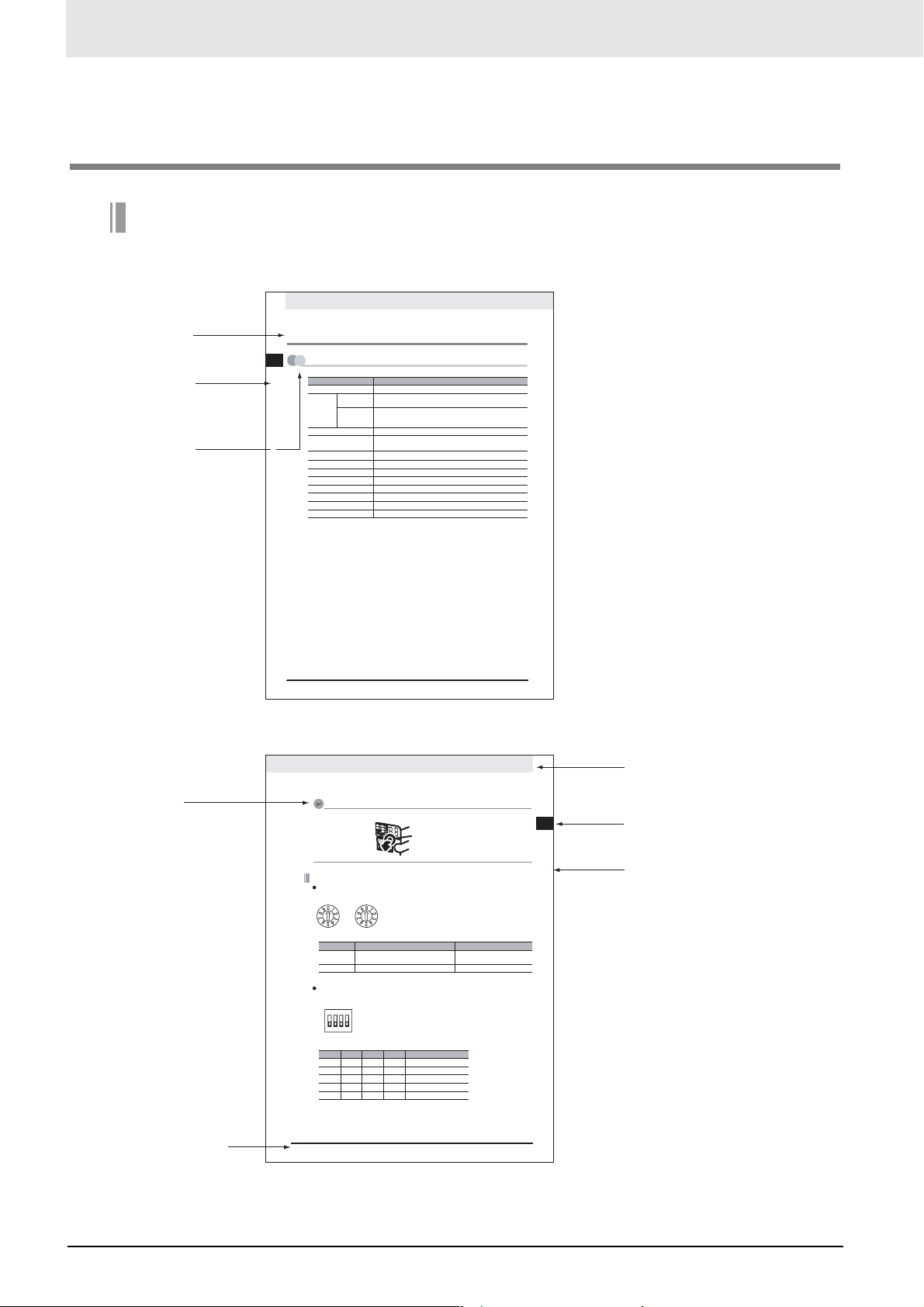
Page Structure
The following page structure is used in this manual.
Level-2 heading
Level-2 heading
Gives the current level-2 heading.
Level-3 heading
Icon
(See next page.)
2-1 Specifications
2
2-1-1 General Specifications
snoit
a
cifi
c
epS
1-2
2 - 1
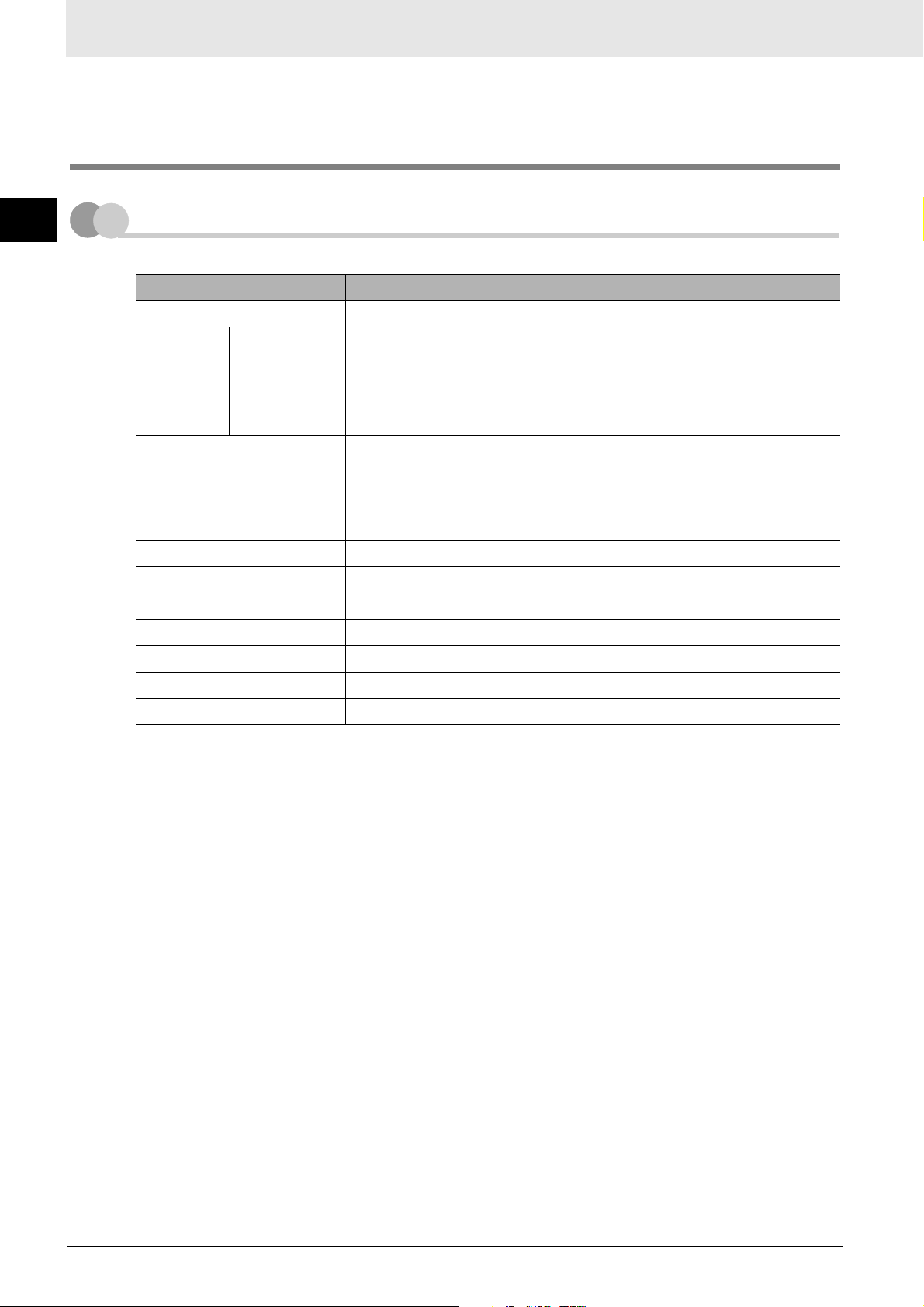
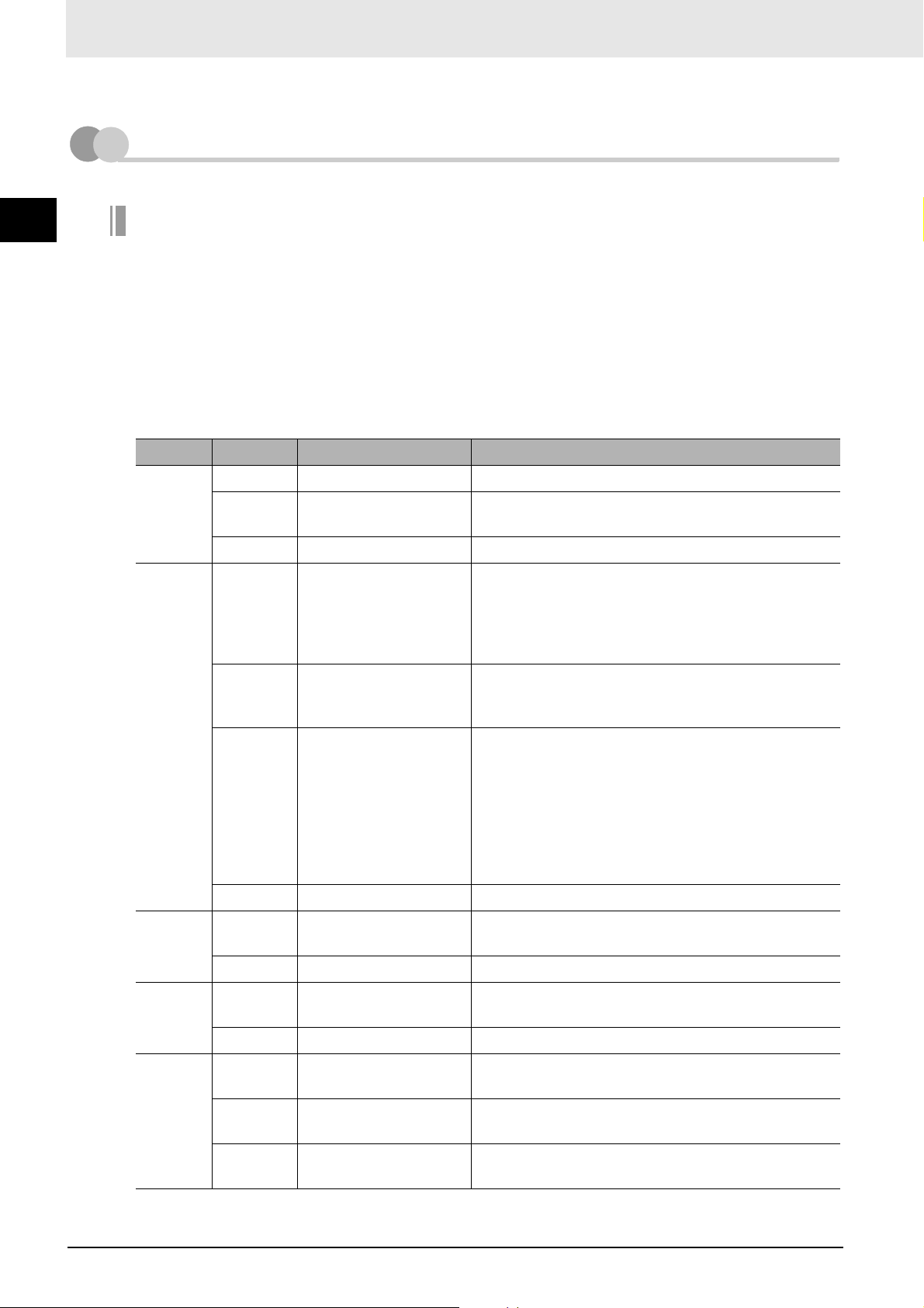
Item Specification
Unit power supply voltage 21.6 to 26.4 VDC (24 VDC ±10%) (Supplied from power supply connector.)
Current
Communications
consumption
Noise immunity Conforms to IEC 61000-4-4, 2.0 kV
Vibration resistance
Shock resistance
Dielectric strength 500 VAC
Installation method Mounted to DIN Track or by using M4 screws
Ambient operating temperature 0 to 55°C
Ambient operating humidity 10% to 90% (with no condensation)
Ambient storage temperature −25 to 65°C
Weight 110 g max.
Ambient operating atmosphere No corrosive gases
Supplemental Information
To press the CompoNet setting buttons, open the cover as shown below.
3.80 A at 24 VDC
power supply
0.13 A at 24 VDC
Internal current
power
consumption
Malfunction: 10 to 60 Hz with 0.7-mm double amplitude, 60 to 150 Hz, 50 m/s
for 80 min in X, Y, and Z directions
2
150 m/s
, 3 times in 6 directions on 3 axes
Open from here.
CompoNet Gateway Unit for CC-Link Operation Manual
Description of Gateway Unit
2
Level-1 heading
Gives the current level-1 heading.
2
Page tab
Gives the number of the level-1 section.
Level-3 heading
Gives the current level-3 heading.
Manual name
CC-Link Communications Section
Station Number Switch
The station number switch sets the station number of the Gateway Unit on the CC-Link network.
X10 X1
Number Description Remarks
1 to 61
Set the station number of the Gateway Unit on the
CC-Link network.
0 or 62 to 99
Do not set. The L ERR indicator will light.
Baud Rate DIP Switch
The baud rate DIP switch sets the baud rate of the Gateway Unit on the CC-Link network.
Set the baud rate of the Gateway Unit to the same value as the CC-Link Master Unit.
O
N
123
4
• Baud Rate Setting
Pin 1 Pin 2 Pin 3 Pin 4*1 Baud rate
OFF OFF OFF OFF
OFF OFF ON O FF
OFF O N OFF OFF
OFF ON ON OFF
ON OFF OFF OFF
*1 Always leave pin 4 turned OFF. It is reserved.
CompoNet Gateway Unit for CC-Link Operation Manual
156 kbps (default)
625 kbps
2.5 Mbps
5 Mbps
10 Mbps
sgnitteS hctiwS 2-2-2
Default: 00
2 - 10
This illustration is provided only as a sample.
The page shown in the illustration does not necessarily appear in this manual.
2
CompoNet Gateway Unit for CC-Link Operation Manual
Page 5

Using this Manual
Icons
The following icons are used in this manual.
Precautions for Safe Use
Precautions on what to do and what not to do to ensure using the product safely.
Precautions for Correct Use
Precautions on what to do and what not to do to ensure proper operation and performance.
Supplemental Information
Supplemental information to increase understanding.
Additional Information
Additional information or information for reference in product application.
CompoNet Gateway Unit for CC-Link Operation Manual
3
Page 6

Read and Understand this Manual
Read and Understand this Manual
Please read and understand this manual before using the product. Please consult your OMRON
representative if you have any questions or comments.
Warranty and Limitations of Liability
WARRANTY
OMRON's exclusive warranty is that the products are free from defects in materials and workmanship for a
period of one year (or other period if specified) from date of sale by OMRON.
OMRON MAKES NO WARRANTY OR REPRESENTATION, EXPRESS OR IMPLIED, REGARDING NONINFRINGEMENT, MERCHANTABILITY, OR FITNESS FOR PARTICULAR PURPOSE OF THE
PRODUCTS. ANY BUYER OR USER ACKNOWLEDGES THAT THE BUYER OR USER ALONE HAS
DETERMINED THAT THE PRODUCTS WILL SUITABLY MEET THE REQUIREMENTS OF THEIR
INTENDED USE. OMRON DISCLAIMS ALL OTHER WARRANTIES, EXPRESS OR IMPLIED.
LIMITATIONS OF LIABILITY
OMRON SHALL NOT BE RESPONSIBLE FOR SPECIAL, INDIRECT, OR CONSEQUENTIAL DAMAGES,
LOSS OF PROFITS OR COMMERCIAL LOSS IN ANY WAY CONNECTED WITH THE PRODUCTS,
WHETHER SUCH CLAIM IS BASED ON CONTRACT, WARRANTY, NEGLIGENCE, OR STRICT
LIABILITY.
In no event shall the responsibility of OMRON for any act exceed the individual price of the product on which
liability is asserted.
IN NO EVENT SHALL OMRON BE RESPONSIBLE FOR WARRANTY, REPAIR, OR OTHER CLAIMS
REGARDING THE PRODUCTS UNLESS OMRON'S ANALYSIS CONFIRMS THAT THE PRODUCTS
WERE PROPERLY HANDLED, STORED, INSTALLED, AND MAINTAINED AND NOT SUBJECT TO
CONTAMINATION, ABUSE, MISUSE, OR INAPPROPRIATE MODIFICATION OR REPAIR.
4
CompoNet Gateway Unit for CC-Link Operation Manual
Page 7

Read and Understand this Manual
Application Considerations
SUITABILITY FOR USE
OMRON shall not be responsible for conformity with any standards, codes, or regulations that apply to the
combination of products in the customer's application or use of the products.
At the customer's request, OMRON will provide applicable third party certification documents identifying
ratings and limitations of use that apply to the products. This information by itself is not sufficient for a
complete determination of the suitability of the products in combination with the end product, machine,
system, or other application or use.
The following are some examples of applications for which particular attention must be given. This is not
intended to be an exhaustive list of all possible uses of the products, nor is it intended to imply that the uses
listed may be suitable for the products:
• Outdoor use, uses involving potential chemical contamination or electrical interference, or conditions or
uses not described in this manual.
• Nuclear energy control systems, combustion systems, railroad systems, aviation systems, medical
equipment, amusement machines, vehicles, safety equipment, and installations subject to separate
industry or government regulations.
• Systems, machines, and equipment that could present a risk to life or property.
Please know and observe all prohibitions of use applicable to the products.
NEVER USE THE PRODUCTS FOR AN APPLICATION INVOLVING SERIOUS RISK TO LIFE OR
PROPERTY WITHOUT ENSURING THAT THE SYSTEM AS A WHOLE HAS BEEN DESIGNED TO
ADDRESS THE RISKS, AND THAT THE OMRON PRODUCTS ARE PROPERLY RATED AND INSTALLED
FOR THE INTENDED USE WITHIN THE OVERALL EQUIPMENT OR SYSTEM.
PROGRAMMABLE PRODUCTS
OMRON shall not be responsible for the user's programming of a programmable product, or any
consequence thereof.
CompoNet Gateway Unit for CC-Link Operation Manual
5
Page 8
Read and Understand this Manual
Disclaimers
CHANGE IN SPECIFICATIONS
Product specifications and accessories may be changed at any time based on improvements and other
reasons.
It is our practice to change model numbers when published ratings or features are changed, or when
significant construction changes are made. However, some specifications of the products may be changed
without any notice. When in doubt, special model numbers may be assigned to fix or establish key
specifications for your application on your request. Please consult with your OMRON representative at any
time to confirm actual specifications of purchased products.
DIMENSIONS AND WEIGHTS
Dimensions and weights are nominal and are not to be used for manufacturing purposes, even when
tolerances are shown.
PERFORMANCE DATA
Performance data given in this manual is provided as a guide for the user in determining suitability and does
not constitute a warranty. It may represent the result of OMRON's test conditions, and the users must
correlate it to actual application requirements. Actual performance is subject to the OMRON Warranty and
Limitations of Liability.
ERRORS AND OMISSIONS
The information in this manual has been carefully checked and is believed to be accurate; however, no
responsibility is assumed for clerical, typographical, or proofreading errors, or omissions.
6
CompoNet Gateway Unit for CC-Link Operation Manual
Page 9
Safety Precautions
Definition of Precautionary Information
The following notation is used in this manual to provide precautions required to ensure safe usage of
the CompoNet Gateway Unit for CC-Link.
The safety precautions that are provided are extremely important to safety. Always read and heed the
information provided in all safety precautions.
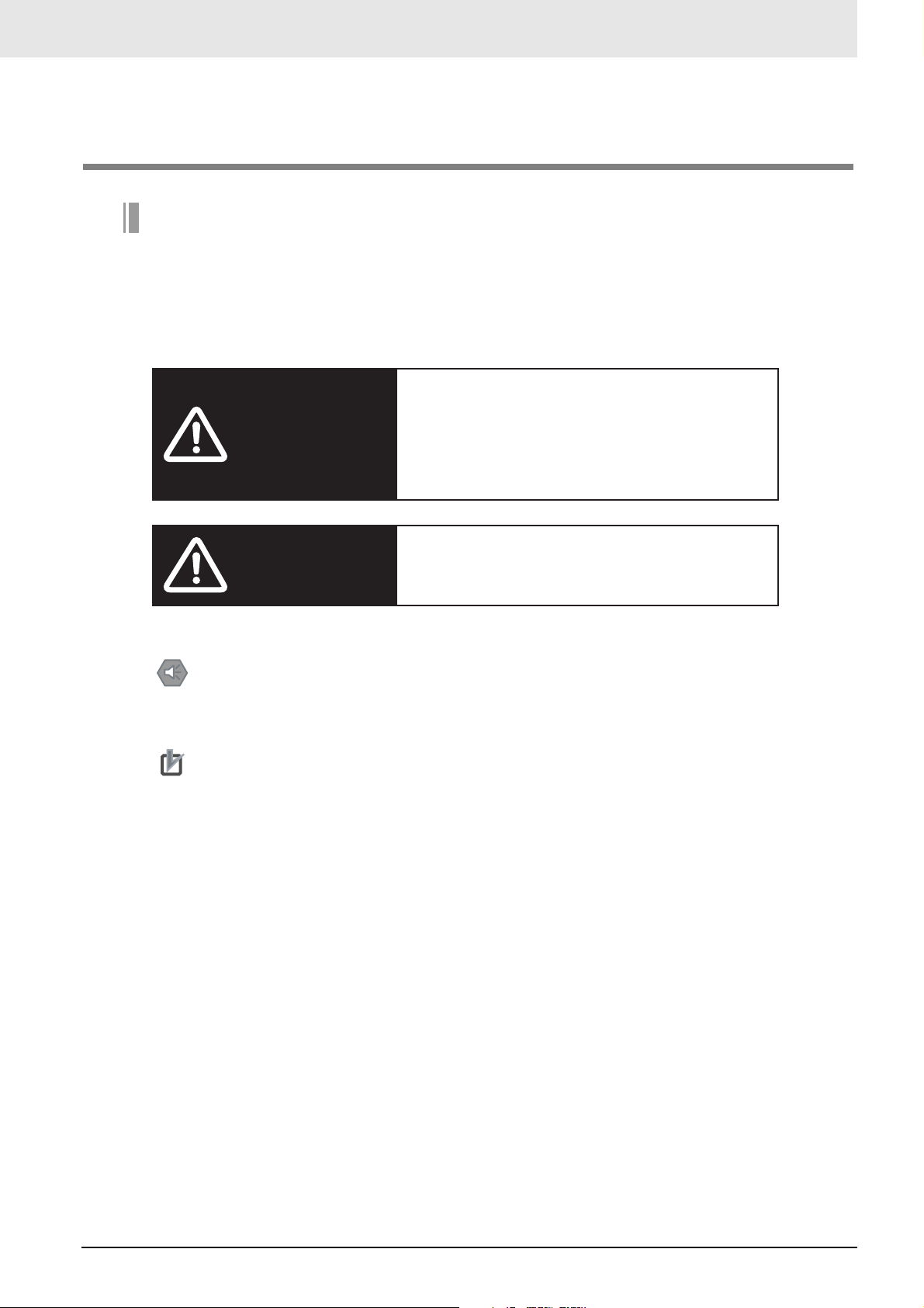
WARNING
Safety Precautions
Indicates a potentially hazardous situation
which, if not avoided, will result in minor or
moderate injury, or may result in serious
injury or death. Additionally there may be
significant property damage.
Indicates a potentially hazardous situation
Caution
Precautions for Safe Use
Precautions on what to do and what not to do to ensure using the product safely.
Precautions for Correct Use
Precautions on what to do and what not to do to ensure proper operation and performance.
which, if not avoided, may result in minor
or moderate injury, or property damage.
CompoNet Gateway Unit for CC-Link Operation Manual
7
Page 10
Safety Precautions
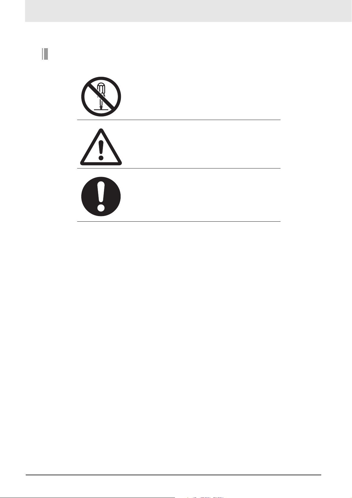
Symbols
The circle and slash symbol indicates operations that you
must not do.
The specific operation is shown in the circle and explained
in text.
The symbol at the left means "do not disassemble."
The triangle symbol indicates precautions (including warnings).
The specific operation is shown in the triangle and explained in text.
The symbol at the left is for a general precaution.
The filled circle symbol indicates operations that you must
do.
The specific operation is shown in the circle and explained
in text.
The symbol at the left shows a general precaution for
something that you must do.
8
CompoNet Gateway Unit for CC-Link Operation Manual
Page 11
WARNING
Always input the voltage and current to the Unit within the
specified ranges.
Using a voltage or current outside the specified range may result
in malfunction or fire.
Do not touch any part of the terminal section or disassemble the
Unit and touch internal parts while the power is being supplied.
Do not apply power while the cover is open.
Doing so may result in electric shock.
Safety Precautions
Fail-safe measures must be taken by the customer to ensure
safety in the event of incorrect, missing, or abnormal signals
caused by broken signal lines, momentary power interruptions, or
other causes. Serious accidents may result from abnormal
operation if proper measures are not provided.
Provide safety measures in external circuits (i.e., not in the
Programmable Controller), including the following items, to
ensure safety in the system if an abnormality occurs due to
malfunction of the PLC or an external factor affecting the PLC
operation.
Serious accidents may result from abnormal operation if proper
measures are not provided.
• Emergency stop circuits, interlock circuits, limit circuits, and
similar safety measures must be provided in external control
circuits (i.e., not in Slave Units or Repeater Units).
• The outputs from Slave Units or Repeater Units may remain
ON or OFF due to deposits on or burning of the output relays,
or destruction of the output transistors. As a countermeasure
for such problems, external safety measures (i.e., not in Slave
Units or Repeater Units) must be provided to ensure safety in
the system.
• When the 24-VDC output (service power supply) from a Slave
Unit or Repeater Unit is overloaded or shortcircuited, the
voltage may drop and result in the outputs being turned OFF.
As a countermeasure for such problems, external safety measures (i.e., not in Slave Units or Repeater Units) must be provided to ensure safety in the system.
CompoNet Gateway Unit for CC-Link Operation Manual
9
Page 12
Safety Precautions
Confirm safety at the destination slave device before changing or
transferring parameters to another node. Changing or
transferring parameters without confirming safety may result in
unexpected equipment operation.
The output status from a slave device when problems occur in
communications will depend on the specifications of the slave
device. When using devices with outputs, confirm operating
specifications for communications error and implement suitable
safety measures.
Caution
10
CompoNet Gateway Unit for CC-Link Operation Manual
Page 13

Precautions for Safe Use
Observe the following precautions when using a CompoNet Gateway Unit for CC-Link.
z Power Supply
• Always use the power supply voltages specified in this manual.
• Take appropriate measures to ensure that the specified power with the rated voltage and frequency is
supplied. Be particularly careful in places where the power supply is unstable.
• Always turn OFF the power supply to the PLC, Gateway Unit, Slave Units, and communications
before attempting any of the following.
• Mounting or dismounting any Units
• Assembling Units
• Setting rotary switches
• Connecting or wiring cables
• Connecting or disconnecting connectors
Precautions for Safe Use
z Installation
• Install and wire Units correctly as described in this manual.
• Before touching a Unit, be sure to first touch a grounded metallic object in order to discharge any
static build-up.
• Make sure that the terminal blocks, connectors, communications cables, and other items with locking
devices are properly locked into place.
• When mounting Units to DIN Track or mounting brackets, mount them securely.
• Make sure that all the Unit mounting screws and cable connector screws are tightened to the torque
specified in this manual.
• Use only the specified communications cables and connectors.
• Use correct wiring parts and wiring tools when wiring the cables in the CC-Link and CompoNet systems.
z Wiring
• Wire Units correctly as described in this manual.
• Double-check all wiring and switch settings before turning ON the power supply.
• Confirm polarity before wiring terminals.
• Observe the following precautions when wiring communications cables.
• Separate the communications cables from power lines and high-tension lines.
• Do not fold communications cables.
• Do not pull on the communications cables or bend them past their natural bending radius.
• Always lay communications cable inside ducts.
• Observe voltage specifications when wiring communications paths and power supplies and when wiring I/O crossovers. Incorrect wiring may result in malfunctions.
• Do not apply voltages or connect loads to the Output Units in excess of the maximum switching
capacity.
• When using Flat Cable I (standard or sheathed) or Flat Cable II (sheathed) for more than one CompoNet system, do not bundle the Flat Cables and separate them from each other by at least 5 mm.
• Do not apply power while the cover is open.
• Use only the specified communications cables and connectors.
• Observe the connection distance specifications when connecting communications cables.
• Make sure that metal scraps do not enter a Unit when wiring or processing it.
CompoNet Gateway Unit for CC-Link Operation Manual
11
Page 14

Precautions for Safe Use
z Handling
• Use the special packing box when transporting a Unit. Also, protect the Unit from being exposed to
excessive vibration or impact during transportation.
• Do not drop the Units or expose them to excessive vibration or impact. Doing so may result in failure
or malfunction.
• Check the user program for proper execution before actually running it on the Unit.
• Do not attempt to dismantle the Unit for repairs or modify it in any way.
• Confirm that no adverse effect will occur in the system before attempting any of the following.
• Changing the operating mode of the PLC
• Starting or stopping the user program
• Force-setting/force-resetting any bit in memory
• Changing the present value of any word or any set value in the user program
• Performing I/O tests
• Using the user compensation functions for an Output Unit
• Do not use organic thinners to clean the Unit. Use commercially available alcohol.
z External Circuits
• Install external breakers and take other safety measures against short-circuiting in external wiring.
• Fail-safe measures must be taken by the customer to ensure safety in the event of incorrect, missing,
or abnormal signals caused by broken signal lines, momentary power interruptions, or other causes.
• Construct the control circuits so that the power supply to the CompoNet Gateway Unit turns ON only
after the power supply to I/O Slave Units. If the power supply to I/O Slave Units is turned ON after the
power supply to the CompoNet Gateway Unit, normal operation may be temporarily inhibited.
12
CompoNet Gateway Unit for CC-Link Operation Manual
Page 15

Precautions for Correct Use
• Follow the instructions in this manual to correctly perform installation.
The Unit may fail if it is not installed correctly.
• Observe the voltage specifications when wiring the power supply. An incorrect voltage may result in
malfunctions.
• Take appropriate and sufficient countermeasures when using the Unit in the following locations:
• Locations subject to static electricity or other forms of noise
• Locations subject to strong electromagnetic fields
• Locations subject to possible exposure to radioactivity
• Locations close to power supplies
• Do not install the Unit in the following locations:
• Locations subject to direct sunlight
• Locations subject to temperatures or humidity outside the range specified in the specifications
• Locations subject to condensation as the result of severe changes in temperature
• Locations subject to corrosive or flammable gases
• Locations subject to dust (especially iron dust) or salts
• Locations subject to exposure to water, oil, or chemicals
• Locations subject to shock or vibration
• Take appropriate and sufficient countermeasures when installing the Unit in the following locations:
• Locations subject to static electricity or other forms of noise
• Locations subject to strong electromagnetic fields
• Locations subject to possible exposure to radioactivity
• Locations close to power supplies
Precautions for Correct Use
CompoNet Gateway Unit for CC-Link Operation Manual
13
Page 16

Conformance to EC Directives
Conformance to EC Directives
Applicable Directives
• EMC Directive
Concepts
z EMC Directive
The CompoNet Gateway Unit is an electrical device that is built into other machines. To enable more
easily building it into other machines, it has been checked for conformity to EMC standards.* EMCrelated performance of the Unit will vary depending on the configuration, wiring, and other conditions of
the equipment or control panel on which it is installed. Whether the products conform to the standards
in the system used by the customer, therefore, must be checked by the customer.
Applicable EMC (Electromagnetic Compatibility) standards are as follows: EMS (Electromagnetic Susceptibility):
*
EN 61131-2 and EN 61000-6-2, EMI (Electromagnetic Interference): EN 61131-2 and EN 61000-6-4 (Radiated
emission: 10-m regulations).
z Conformance to EC Directives
The CompoNet Gateway Unit complies with EC Directives. To ensure that the machine in which the Unit
is used complies with EC Directives, the Unit must be installed as follows:
• The Unit must be installed within a control panel.
• You must use reinforced insulation or double insulation for the DC power supplies for communications, internal power, and I/O. The DC power supplies must provide stable power even when a
momentary power interruption of 10 ms occurs in the input. *
• Products complying with EC Directives also conform to the emission standards (EN 61131-2 and EN
61000-6-4). Radiated emission characteristics (10-m regulations) may vary depending on the configuration of the control panel used, other devices connected to the control panel, wiring, and other conditions.
• Compliance was confirmed for I/O wiring of less than 30 m.
* EMC standard compliance was confirmed with an OMRON S82J Power Supply.
• This is a Class A product (designed for industrial environments). Radio interference may occur if it is
used in a residential area. If that occurs, suitable countermeasures will be required.
14
CompoNet Gateway Unit for CC-Link Operation Manual
Page 17

Trademarks
• “CC-Link” is a registered trademark of Mitsubishi Electric Corporation.
• “GX-Developer” is a registered trademark of Mitsubishi Electric Corporation.
• “CompoNet” is a registered trademark of the ODVA (Open DeviceNet Vendors Association, Inc.).
Other system names and product names that appear in this manual are the trademarks or registered
trademarks of their respective companies.
Trademarks
CompoNet Gateway Unit for CC-Link Operation Manual
15
Page 18
Related Manuals
Related Manuals
The following manuals are related to CompoNet. Use them together with this manual whenever
required.
Cat. No. Manual name Contents
W489
(this manual)
W484 CompoNet Analog I/O
W456 CS/CJ-series CompoNet
W457 CompoNet Slave Units and
CompoNet Gateway Unit
for CC-Link Operation
Manual
Slaves with Numerical Indicator Operation Manual
Master Unit Operation
Manual
Repeater Unit Operation
Manual
Specifications and wiring procedures for the GQ-CRM21
CompoNet Gateway Unit for CC-Link.
Specifications for the CRT1-VAD02SD, CRT1VAD02MLD, CRT1-VDA02SD, and CRT1-VDA02MLD
CompoNet Analog I/O Slaves.
CompoNet network overview, communications specifications, and wiring procedures for CS/CJ-series CompoNet Master Units.
Specifications for CompoNet Slaves Units and Repeater
Units.
16
CompoNet Gateway Unit for CC-Link Operation Manual
Page 19

Table of Contents
About this Manual .......................................................................................................................... 1
Using this Manual .......................................................................................................................... 2
Read and Understand this Manual ................................................................................................ 4
Safety Precautions......................................................................................................................... 7
Precautions for Safe Use............................................................................................................. 11
Precautions for Correct Use ........................................................................................................ 13
Conformance to EC Directives ....................................................................................................14
Trademarks .................................................................................................................................. 15
Related Manuals.......................................................................................................................... 16
Overview
1-1 Overview..................................................................................................................................... 1-1
1-1-1 Overview of Gateway Unit............................................................................................................ 1-1
1-1-2 Gateway Unit Features ................................................................................................................ 1-2
Description of Gateway Unit
2-1 Specifications ............................................................................................................................. 2-1
2-1-1 General Specifications................................................................................................................. 2-1
2-1-2 CC-Link Communications Specifications..................................................................................... 2-2
2-1-3 CompoNet Communications Specifications................................................................................. 2-3
2-2 Component Names and Functions ............................................................................................. 2-4
2-2-1 Indications.................................................................................................................................... 2-5
2-2-2 Switch Settings ............................................................................................................................ 2-8
2-2-3 Terminal Arrangement ............................................................................................................... 2-11
2-2-4 Dimensions ................................................................................................................................ 2-12
Wiring and Settings
3-1 Overview of Operating Procedures.............................................................................................3-1
3-1-1 Basic Startup Procedures ............................................................................................................ 3-1
3-1-2 Procedure for Using the Registration Table .................................................................................3-3
3-2 Installation Method ..................................................................................................................... 3-4
3-2-1 Mounting to a Control Panel ........................................................................................................ 3-4
3-3 Wiring ......................................................................................................................................... 3-5
3-3-1 General Wiring Precautions......................................................................................................... 3-5
3-3-2 Special Connector Tools .............................................................................................................. 3-5
3-4 Wiring the Power Supply ............................................................................................................ 3-6
3-4-1 Wiring the Power Supply to the Gateway Unit ............................................................................. 3-6
3-4-2 Power Supply Wiring for CompoNet Slave Units and the CompoNet Network ............................ 3-7
3-5 Wiring the CompoNet Network ................................................................................................. 3-10
3-5-1 Wiring Methods for the CompoNet Network .............................................................................. 3-10
3-6 Wiring the CC-Link Network ..................................................................................................... 3-11
3-6-1 Recommended Materials and Tools .......................................................................................... 3-11
3-6-2 Wiring the Connector ................................................................................................................. 3-12
3-7 Communications Settings......................................................................................................... 3-13
3-7-1 CompoNet Settings.................................................................................................................... 3-13
3-7-2 CC-Link Settings........................................................................................................................ 3-14
Remote I/O Communications
4-1 Exchanging Data ........................................................................................................................ 4-1
4-1-1 Basic Communications Operations.............................................................................................. 4-1
4-1-2 Confirming Normal Slave Unit Operation in Communications Modes 0 to 3 ............................... 4-3
4-1-3 Registration Table ........................................................................................................................ 4-5
Table of Contents
CompoNet Gateway Unit for CC-Link Operation Manual
17
Page 20

Table of Contents
4-2 Memory Map............................................................................................................................... 4-8
4-2-1 Overview ......................................................................................................................................4-8
4-2-2 I/O Memory Allocations According to Communications Modes ................................................... 4-8
4-2-3 Memory Map for Each Communications Mode............................................................................4-9
4-2-4 Status Area Allocations ..............................................................................................................4-10
4-2-5 Node Address Types on the CompoNet Network....................................................................... 4-14
4-2-6 Data Allocations for Word Slave Units........................................................................................4-15
4-2-7 Data Allocations for Bit Slave Units ............................................................................................ 4-21
4-3 Remote I/O Communications Performance .............................................................................. 4-22
Troubleshooting
5-1 Troubleshooting CompoNet Network Errors ............................................................................... 5-1
5-1-1 CompoNet Network Errors ...........................................................................................................5-1
5-1-2 Troubleshooting Sequence When an Error Occurs...................................................................... 5-1
5-2 Troubleshooting CC-Link Network Errors ................................................................................... 5-5
Appendices
A-1 Allocations According to Communications Modes......................................................... Appendix-1
A-2 Status Area Allocations According to Communications Modes ................................... Appendix-12
Revision History
18
CompoNet Gateway Unit for CC-Link Operation Manual
Page 21

Overview
1
1-1 Overview............................................................................ 1-1
Page 22
1
1-1 Overview
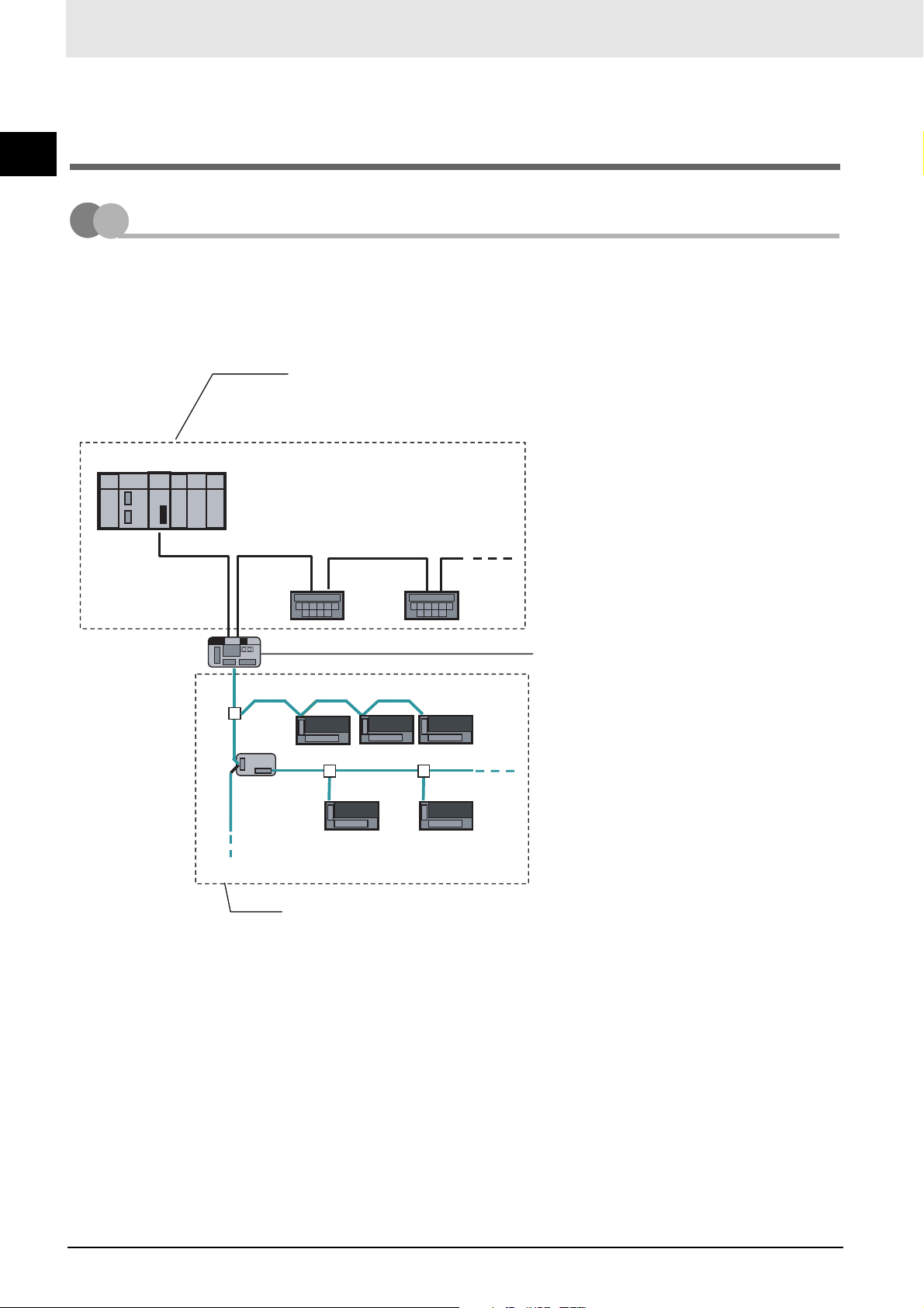
1-1-1 Overview of Gateway Unit
The GQ-CRM21 CompoNet Gateway Unit for CC-Link provides one CC-Link port and one CompoNet
1-1 Overview
CC-Link Master Unit
port. It cyclically transfers I/O data between the CompoNet Slave Units and the CC-Link Master Unit.
The GQ-CRM21 CompoNet Gateway Unit for CC-Link is referred to as the “Gateway Unit” in this manual.
CC-Link Network
Refer to CC-Link documentation from Mitsubishi Electric Corporation
or other sources for details on CC-Link.
Remote
stations
Repeater
Unit
Gateway Unit
In the CC-Link system, the Gateway Unit
is set as a remote device station with a
4-station allocation.
Slave Units
Slave Units
CompoNet Network
Refer to the CompoNet Slave Unit and Repeater Unit Operation Manual
(Cat. No. W457) for the specifications of CompoNet networks.
Refer to documentation for individual Slave Units and Repeater Units for
details on those Units.
Gateway Unit settings and wiring are
described later in this manual.
1 - 1
CompoNet Gateway Unit for CC-Link Operation Manual
Page 23

Overview
1-1-2 Gateway Unit Features
A Gateway Unit can be used to take advantage of CompoNet features to simplify wiring.
z A Selection of Communications Cables
The following communications cables can be used with CompoNet systems: Round Cable I
(2-conductor), Round Cable II (4-conductor), Flat Cable I (standard), and Flat Cable II (sheathed).
Note: Refer to the CompoNet Slave Unit and Repeater Unit Operation Manual (Cat. No. W457) for details on
cable types.
z Multinode Connections
CompoNet systems can be used for multinode, high-density remote I/O communications.
Maximum I/O capacity: 2,560 points
Maximum nodes: 384 nodes per Gateway Unit
Up to 6,144 CompoNet Slave Units can be connected to a CC-Link Master Unit. (Communications
mode 4 must be set.)
z Bit-level Distribution
CompoNet Slave Units with industry-standard e-CON connectors, clamping terminal blocks, or small
connectors can be used to distribute I/O at the bit level. This enables distributed control in distributed
devices, such as sensors and other devices located over a wide area on conveyors or in warehouses.
1
1-1-2 Gateway Unit Features
z Easy Installation and Setup
CompoNet systems can be easily installed and set up.
• Seven-segment Display
The number of connected CompoNet Slave Units is shown on the seven-segment display.
This enables easily checking system operation.
• Participation Flags and Communications Error Flags
The network participation status of CompoNet Slave Units can be checked at the PLC.
When a CompoNet Slave Unit joins the network, a Participation Flag that corresponds to the node
address of the Unit turns ON. If a CompoNet Slave Unit that was participating in the network is
disconnected from the network, a Communications Error Flag that corresponds to the node
address of the Unit turns ON. (Communications mode 0 to 3 must be set.)
• Automatic Baud Rate Detection
The CompoNet Slave Units will automatically detect and use the baud rate that is set in the Gateway Unit. Setting the baud rate is not necessary for any of the CompoNet Slave Units.
z Repeater Units for Greater Flexibility
Repeater Units can be used in a CompoNet network to enable the following network expansions.
• Extending the cable length
• Increasing the number of nodes
• Branching from the trunk line
• Changing the type of cable
Repeater Units can be used to extend up to two segment layers (called sub-trunk lines) from the
trunk line. Up to 64 Repeater Units can be connected per Gateway Unit and up to 32 Repeater Units
can be connected per segment.
Note: Supply communications power to a sub-trunk line from the Repeater Unit.
Refer to the CompoNet Slave Unit and Repeater Unit Operation Manual (Cat. No. W457) for detailed wiring methods.
CompoNet Gateway Unit for CC-Link Operation Manual
1 - 2
Page 24

z Easy Maintenance with Complete System Monitoring Functions
1
1-1 Overview
The CompoNet Network is constantly monitored to enable confirming system safety by quickly identifying errors and checking communications status.
• Gateway Unit Detection of Network Participation, Errors, and Status
When a CompoNet Slave Unit joins the network, a Participation Flag that corresponds to the node
address of the Unit turns ON. If a CompoNet Slave Unit that was participating in the network is
disconnected from the network, a Communications Error Flag that corresponds to the node
address of the Unit turns ON.
Network status, such as communications errors and duplicated Slave Unit node addresses, and
Slave Unit diagnostic results are detected by the Gateway Unit and displayed on the seven-segment display on the front panel and reflected in the Status Flags. (Communications mode 0 to 3
must be set.)
• Registration Table
A table of the Slave Units that should be participating at the nodes (including the node addresses
and corresponding Slave Unit model numbers) can be registered to verify the Slave Units actually
participating in the network and prevent unregistered Slave Units from participating in the network.
• Communications Status on Gateway Unit Seven-segment Display
The seven-segment display on the front of the Gateway Unit can be used to check communications status. The number of connected nodes is normally displayed, but if an error occurs, the
error code is displayed in hexadecimal and the error node address is displayed in decimal.
1 - 3
CompoNet Gateway Unit for CC-Link Operation Manual
Page 25

Description of Gateway Unit
2-1 Specifications ................................................................... 2-1
2-2 Component Names and Functions .................................2-4
2
Page 26
2-1 Specifications
2
2-1 Specifications
2-1-1 General Specifications
Item Specification
Unit power supply voltage 21.6 to 26.4 VDC (24 VDC±10%) (Supplied from power supply connector.)
Current
consumption
Noise immunity Conforms to IEC 61000-4-4, 2.0 kV
Vibration resistance
Shock resistance
Dielectric strength 500 VAC
Installation method Mounted to DIN Track or by using M4 screws
Ambient operating temperature 0 to 55°C
Ambient operating humidity 10% to 90% (with no condensation)
Ambient storage temperature −25 to 65°C
Weight 110 g max.
Ambient operating atmosphere No corrosive gases
Communications
power supply
Internal current
power
consumption
3.80 A at 24 VDC
0.13 A at 24 VDC
Malfunction: 10 to 60 Hz with 0.7-mm double amplitude, 60 to 150 Hz, 50 m/s
for 80 min in X, Y, and Z directions
150 m/s
2
, 3 times in 6 directions on 3 axes
2
2 - 1
CompoNet Gateway Unit for CC-Link Operation Manual
Page 27
Description of Gateway Unit
2-1-2 CC-Link Communications Specifications
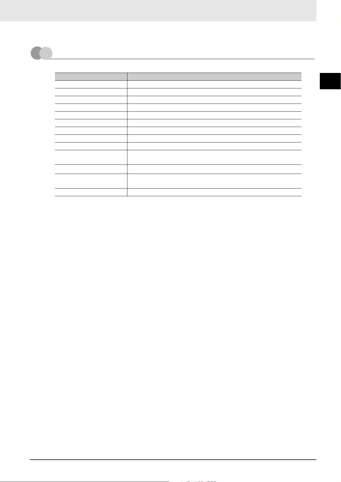
Item Specification
Version CC-Link version 1.10 or 2.00 (Selected using mode switch.)
Baud rate 156 kbps, 625 kbps, 2.5 Mbps, 5 Mbps, or 10 Mbps
Communications method Broadcast polling
Synchronization method Frame synchronization
Encoding NRZI
Transmission path Bus (Conforms to RS-485.)
Transmission format Conforms to HDLC.
Communications media CC-Link cable (shielded, 3-core twisted-pair cable)
Number of connected nodes Must meet specifications of the Master Unit.
Remote stations 1 to 61 (Four station numbers are allocated starting from the specified
station number.)
Error control
RAS functions Automatic recovery function, slave cutoff, data link status checks, offline
Allocated station numbers Allocated four stations numbers as a remote device station
CRC (X16 + X12 + X5 + 1)
testing
2
2-1-2 CC-Link Communications Specifications
CompoNet Gateway Unit for CC-Link Operation Manual
2 - 2
Page 28
2-1-3 CompoNet Communications Specifications
2
2-1 Specifications
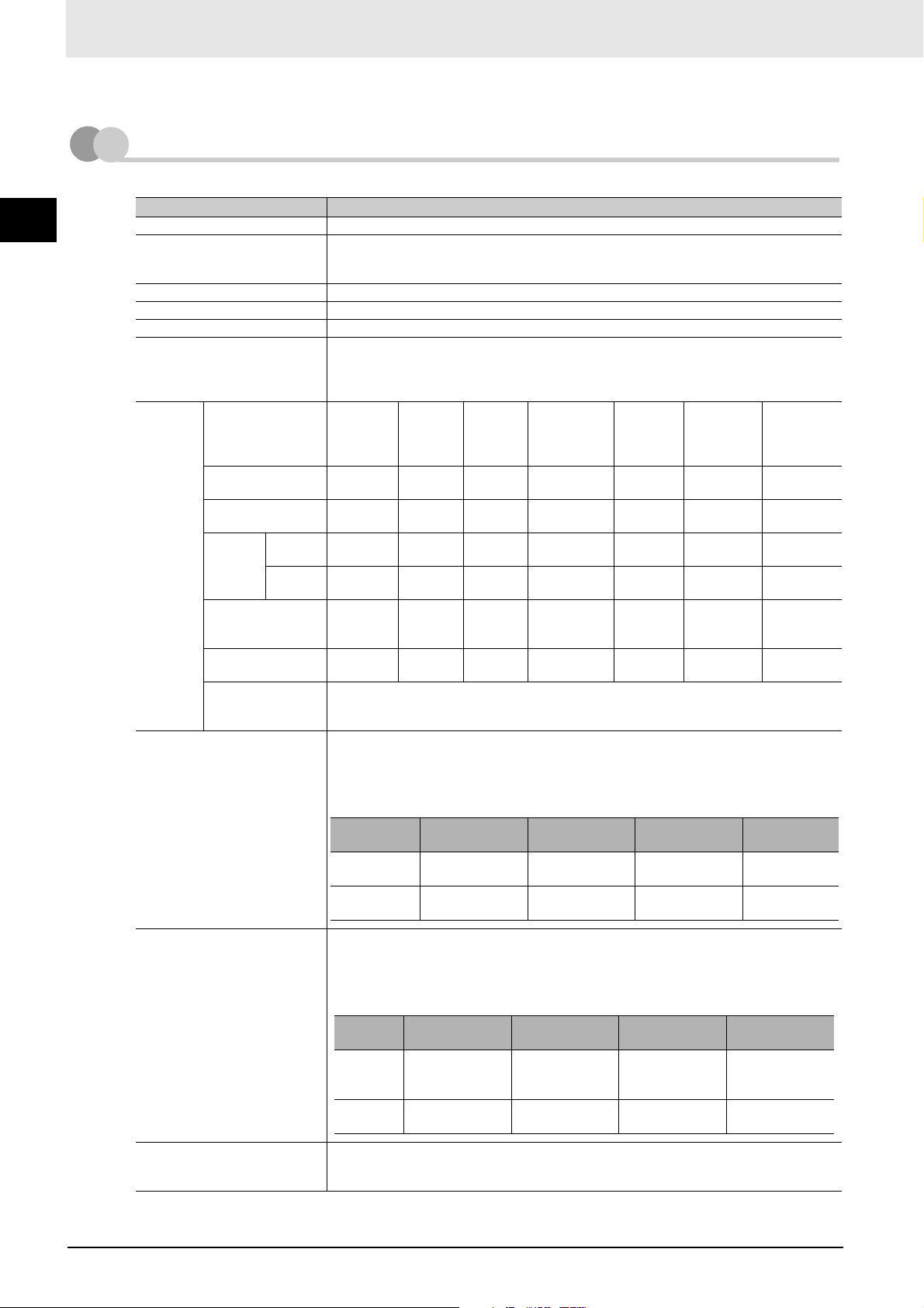
Item Specification
Communications protocol CompoNet protocol
Baud rate 93.75 kbps, 1.5 Mbps, 3 Mbps, or 4 Mbps*1
*1 A baud rate of 4 Mbps is not supported for branch lines and thus cannot be used for
Slave Units with Cables.
Modulation Baseband
Coding Manchester code
Error control Manchester code rules, CRC
Communications media Round Cable I (2-conductor cable, JIS C3306)
Round Cable II (4-conductor cable, JIS C3306)
Flat Cable I (DCA4-4F10 Standard Flat Cable)
Flat Cable II (DCA5-4F10 Sheathed Flat Cable)
Communications
distance
Maximum I/O capacity Word Slave Units: 1,024 inputs and 1,024 outputs (2,048 I/O points total)
Baud rate Max.
segment
length
4 Mbps* 30 m
3 Mbps* 30 m
1.5 Mbps
(Round
Cable I)*
1.5 Mbps (Round
Cable II or Flat
Cable I/II)
93.75 kbps (Round
Cable I)
93.75 kbps (Round
Cable II or Flat
Cable I/II)
No
branches
Branches 30 m
(90 m)
(90 m)
100 m
(300 m)
(90 m)
30 m
(90 m)
500 m
(1,500 m)
Unrestricted wiring is enabled for a total length of 200 m per segment.
Bit Slave Units: 256 inputs and 256 outputs (512 I/O points total)
Branch
length per
segment
0 m 0 m --- --- --- ---
0.5 m 8 m 3 branches/m 1 0 m 0 m
2.5 m 25 m 3 branches/m 3 --- ---
2.5 m 25 m 3 branches/m 3 0.1 m 2 m
6 m 120 m 3 branches/m 3 --- ---
To t al
branch
length per
segment
--- --- --- --- --- ---
Branch
location
restriction
Connected
nodes per
branch
Max. subtrunk length
per segment
Total subtrunk length
per segment
When the Gateway Unit is used, I/O capacities are as follows depending on the CompoNet
communications mode.
Max. number of connected
nodes
Max. number of connected
nodes per trunk line or sub-trunk
line
Communications
mode 0 or 4
Word Slave
Units
Bit Slave Units
Word Slave Units: 64 input nodes and 64 output nodes
Bit Slave Units: 128 input nodes and 128 output nodes
When the Gateway Unit is used, the maximum number of connected nodes is as follows
depending on the CompoNet communications mode.
Word
Slave
Units
Bit Slave
Units
32 nodes (number of Slave Unit and Repeater Unit nodes)
1,024 inputs and
1,024 outputs
256 inputs and
256 outputs
Communications
mode 0 or 4
IN0 to IN63 and
OUT0 to OUT63
IN0 to IN127 and
OUT0 to OUT127
Communications
mode 1 or 5
512 inputs and
512 outputs
192 inputs and
192 outputs
Communications
mode 1 or 5
IN0 to IN31 and
OUT0 to OUT31
IN0 to IN95 and
OUT0 to OUT95
* Lengths given in parentheses are for when two Repeater Units are used.
Communications
mode 2 or 6
256 inputs and
256 outputs
96 inputs and 96
outputs
Communications
mode 2 or 6
IN0 to IN15 and
OUT0 to OUT15
IN0 to IN47 and
OUT0 to OUT47
Communications
mode 3
128 inputs and
128 outputs
32 inputs and
32 outputs
Communications
mode 3
IN0 to IN7 and
OUT0 to OUT7
IN0 to IN15 and
OUT0 to OUT15
2 - 3
CompoNet Gateway Unit for CC-Link Operation Manual
Page 29
Description of Gateway Unit
2-2 Component Names and Functions
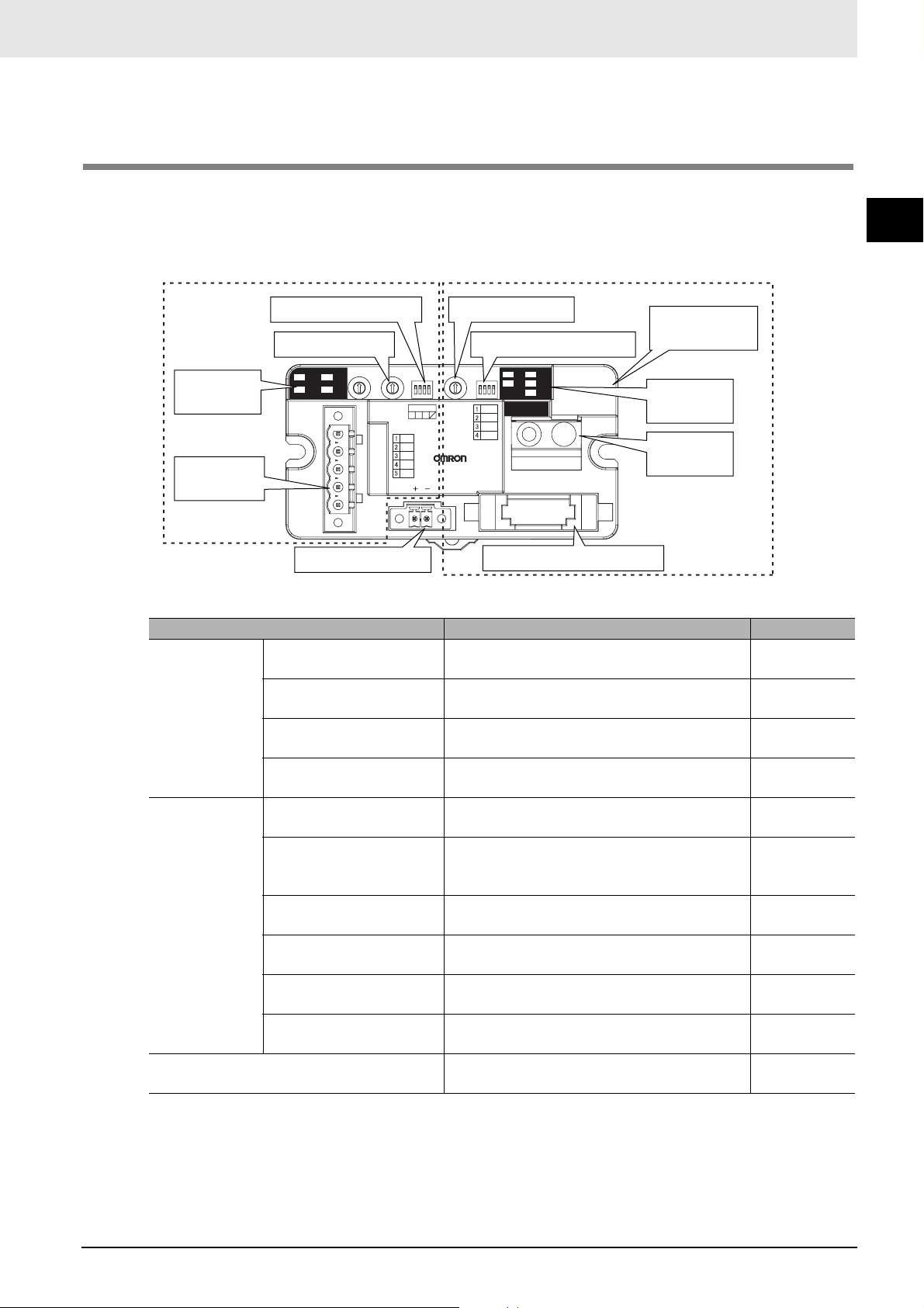
The Gateway Unit is separated into sections, one for CC-Link communications and one for CompoNet
communications.
CompoNet Communications SectionCC-Link Communications Section
Baud rate DIP switch
Station number switch
RUN
L
CC-Link
communications
indicators
CC-Link
communications
connector
SD
L
ERR
RD
Power connector
X10 MODEX1 B.RATE
STATION No.
DA
DB
DG
SLD
FG
DC24V INPUT
Part Description Reference
CC-Link
communications
section
CC-Link communications
indicators
Station number switch Sets the station number of the Gateway Unit on
Baud rate DIP switch Sets the baud rate of the Gateway Unit on the
CC-Link communications
connector
CompoNet
communications
section
CompoNet communications
indicators
CompoNet seven-segment
display
Mode switch Sets the CompoNet communications mode. 2-2-2 Switch
CompoNet DIP switch Enables or disables the baud rate setting and
CompoNet setting buttons Creates the registration table on the CompoNet
CompoNet communications
connector
Power connector Connects to the power supply for the Gateway
Mode switch
124
GQ-CRM21
CompoNet DIP switch
SDNSMS
.
RD
REG
REGIST RESET
DR0
DR1
DCN
REGS
CompoNet communications
connector
.
8 8
CompoNet sevensegment display
CompoNet
communications
indicators
CompoNet
setting buttons
Used to check CC-Link data link status. 2-2-1
Indications
2-2-2 Switch
the CC-Link network.
Settings
2-2-2 Switch
CC-Link network.
Settings
Connects to the CC-Link cable. 2-2-3 Terminal
Arrangement
Used to check the communications status of
CompoNet remote I/O.
Normally shows the number of connected
CompoNet Slave Units. An error code is
2-2-1
Indications
2-2-1
Indications
displayed if a communications error occurs.
Settings
2-2-2 Switch
registration table on the CompoNet network.
Settings
2-2-2 Switch
network, resets the Gateway Unit, etc.
Settings
Connects the CompoNet network cable. 2-2-3 Terminal
Arrangement
2-2-3 Terminal
Unit.
Arrangement
2
CompoNet Gateway Unit for CC-Link Operation Manual
2 - 4
Page 30
2-2-1 Indications
Indications of both CompoNet and CC-Link status are provided on the Gateway Unit.
2
2-2 Component Names and Functions
CompoNet Communications Section
z CompoNet Communications Indicators
The following LED indicators are provided for CompoNet communications.
MS (Module Status): Shows the status of the node itself (two colors: green and red).
NS (Network Status): Shows the status of communications (two colors: green and red).
SD (Send Data): Shows the transmission status from the Gateway Unit to CompoNet (one
color: yellow).
RD (Receive Data): Shows the reception status from CompoNet to the Gateway Unit (one color:
yellow).
REG (Registration): Shows if the registration table is enabled or disabled (one color: green).
Indicator Status Status definition Meaning
MS Lit green Normal The Unit is operating normally.
Lit red Fatal error Unit hardware error, such as a watchdog timer error
(WDT)
Not lit Power OFF/Preparing Power OFF, resetting, or initializing
NS Lit green Online with remote I/O
communications in
progress
Flashing
green
Online with no remote I/O
communications in
progress
Power is being supplied, remote I/O communications have
started, there are no communications errors at any Slave
Unit or Repeater Unit, there are no registration table
errors, and there are no node address duplication errors
for Slave Units or Repeater Units.
Remote I/O communications have not started or have
stopped.
Flashing
red
Not lit Power OFF/Preparing Power OFF, resetting, or initializing
SD Lit yellow Normal transmission Frames are being sent normally from the Gateway Unit to
Not lit No transmission Data is not being sent by the Gateway Unit
RD Lit yellow Normal reception Frames are being received normally from CompoNet
Not lit No reception Data is not being received by the Gateway Unit.
REG Lit green Registration table enabled The registration table has been created and is enabled.
Flashing
green
Not lit Registration table
Non-fatal communications
error
Registration table creation The registration table is being created.
disabled
A communications error has occurred at one or more
Slave Units or Repeater Units.
A verification error (non-existent or unregistered Slave
Unit) has occurred at one or more Slave Units.
Communications have stopped due to a communications
error, an illegal configuration error (number of Repeater
Units) has occurred, or an address duplication error has
occurred at one or more Slave Units or Repeater Units.
CompoNet.
Slave Units.
The registration table has been created.
The registration table is disabled or has not been created.
2 - 5
CompoNet Gateway Unit for CC-Link Operation Manual
Page 31

Description of Gateway Unit
z CompoNet Seven-segment Display
The display operates as shown below during normal operation and when an error occurs.
The information shown on the display during normal operation can be changed by setting pin 3 on
the CompoNet DIP switch (pin 3: DCN (details of connected nodes).
Status
Normal CompoNet DIP
switch pin 3 (DCN
(details of connected
nodes)): OFF
(default)
Displayed
contents
Number of
connected
nodes
Description
Displays the number of Slave Units connected to CompoNet.
If more than 99 Slave Units are connected, the value of the 100s digit is
shown by the dot indicators.
100s digit = 1
Only the left dot is lit.
(Display example for 123)
100s digit = 2
Only the right dot is lit.
2
2-2-1 Indications
CompoNet DIP
switch pin 3 (DCN
(details of connected
nodes)): ON
Detailed
connection
information
• Baud rate
• Number of
nodes for
each Unit
type
(Display example for 233)
100s digit = 3
Both the left and right dots are lit.
(Display example for 323)
• The display will change in the following order.
Baud rate
↓
Total number of nodes
↓
Number of Word Slave Units
i** (Word Input Slave Units) → o** (Word Output Slave Units) →
↓
Number of Bit Slave Units
bi** (Bit Input Slave Units) → bo** (Bit Output Slave Units) →
↓
Baud rate
• The baud rate is indicated as follows:
“_0”: 4 Mbps
“_1”: 3 Mbps
“_2”: 1.5 Mbps
“_3”: 93.75 kbps
• The display of the number of connected nodes is the same as when pin 3
on the CompoNet DIP switch is OFF.
CompoNet Gateway Unit for CC-Link Operation Manual
2 - 6
Page 32

Status
Error Initialization error Error code The error code is shown on the display in hexadecimal.
Communications error The error
2
Displayed
contents
code, node
type, and
applicable
node address
are displayed
in order.
Description
Error code (2-digit hexadecimal) → Slave Unit type →
Node address (3-digit decimal: 100s digit is indicated with 1 bit dot) are
displayed in order (for each error cause).
Note: Error codes are different for inputs and outputs.
Example Error code Slave Unit type
Communications
error
Display Display
appearance
d9 i IN
Display Display
appearance
oOUT
bi Bit Input
Meaning
Unit
2-2 Component Names and Functions
Node address
duplication
Verification error:
Slave Unit
missing.
Verification error:
Unregistered
Slave Unit
Operating error
Note: “Operating errors”
are all errors
except for communications
errors that occur
during Unit operation.
Error code The error code is shown on the display in 2-digit hexadecimal.
Example Error code ---
Illegal
registration table
CC-Link Communications Section
z CC-Link Communications Indicators
bo Bit Output
Unit
r Repeater
Unit
d0 Same as above.
d5 Same as above.
d6 Same as above.
Display Display
appearance
E8 ---
2 - 7
Indicator Status Status definition
L RUN Lit green CC-Link data links are active.
Not lit Communications for CC-Link data links have been interrupted.
L ERR Lit red • A CC-Link data link communications error has occurred or the baud rate of the
Gateway Unit is different from the baud rate of the CC-Link Master Unit.
• The station number switch is set out of range.
Flashing red The setting of the baud rate DIP switch or station number switch was changed while
power was ON.
SD Lit yellow Data is being transmitted normally.
Not lit No data is being transmitted.
RD Lit yellow Data is being received normally.
Not lit No data is being received.
CompoNet Gateway Unit for CC-Link Operation Manual
Page 33

2-2-2 Switch Settings
CompoNet Communications Section
z Mode Switch
This switch sets the communications mode number for the Gateway Unit. It is set to between 0 and 6 on
a decimal rotary switch. The expanded cyclic setting (a network parameter set with the GX-Developer)
in the station information must be set according to the communications mode as shown below.
Description of Gateway Unit
2
2-2-2 Switch Settings
Mode
number
0
(default)
1 Communications
2 Communications
3 Communications
4 Communications
5 Communications
Name
Communications
mode 0
mode 1
mode 2
mode 3
mode 4
mode 5
Connectable node
addresses
Word Slave Unit: IN0 to
IN63 and OUT0 to OUT63
Bit Slave Unit: IN0 to IN127
and OUT0 to OUT127
Word Slave Unit: IN0 to
IN31 and OUT0 to OUT31
Bit Slave Unit: IN0 to IN95
and OUT0 to OUT95
Word Slave Unit: IN0 to
IN15 and OUT0 to OUT15
Bit Slave Unit: IN0 to IN47
and OUT0 to OUT47
Word Slave Unit: IN0 to IN7
and OUT0 to OUT7
Bit Slave Unit: IN0 to IN15
and OUT0 to OUT15
Word Slave Unit: IN0 to
IN63 and OUT0 to OUT63
Bit Slave Unit: IN0 to IN127
and OUT0 to OUT127
Word Slave Unit: IN0 to
IN31 and OUT0 to OUT31
Bit Slave Unit: IN0 to IN95
and OUT0 to OUT95
Control points
Word Slave Unit: 1,024
inputs and 1,024 outputs
Bit Slave Unit: 256 inputs
and 256 outputs
Word Slave Unit: 512
inputs and 512 outputs
Bit Slave Unit: 192 inputs
and 192 outputs
Word Slave Unit: 256
inputs and 256 outputs
Bit Slave Unit: 96 inputs
and 96 outputs
Word Slave Unit: 128
inputs and 128 outputs
Bit Slave Unit: 32 inputs
32 outputs
Word Slave Unit: 1,024
inputs and 1,024 outputs
Bit Slave Unit: 256 inputs
and 256 outputs
Word Slave Unit: 512
inputs and 512 outputs
Bit Slave Unit: 192 inputs
and 192 outputs
CC-Link version and
expanded cyclic
setting
Version 2, octuple
(default)
Version 2, quadruple
Version 2, double
Version 1
Version 2, quadruple
Version 2, double
6 Communications
mode 6
7 to 9 Reserved --- --- ---
Note: Do not set communications mode numbers 7 to 9. They are reserved.
CompoNet Gateway Unit for CC-Link Operation Manual
Word Slave Unit: IN0 to
IN15 and OUT0 to OUT15
Bit Slave Unit: IN0 to IN47
and OUT0 to OUT47
Word Slave Unit: 256
inputs and 256 outputs
Bit Slave Unit: 96 inputs
and 96 outputs
Version 1
2 - 8
Page 34

z DIP Switch
O
N
2
2-2 Component Names and Functions
123
4
• Baud Rate Setting
Pin 1 Pin 2
DR0 DR1
OFF OFF
ON OFF
OFF ON
ON ON
4 Mbps (default)
3 Mbps
1.5 Mbps
93.75 kbps
Description
The CompoNet Slave Units will automatically detect and use the baud rate that is set on pin 1 (DR0)
and pin 2 (DR1). Setting the baud rate is not necessary for any of the Slave Units.
• Details of Connected Nodes
Pin Name ON OFF
3 Details of Connected Nodes
(DCN)
Details of the connected nodes
will be displayed.
The total number of
connected nodes will be
displayed.
If pin 3 (DCN) is turned ON, details on the connected nodes (baud rate, total number of connected
nodes, numbers of I/O Word Slave Units, and numbers of I/O Bit Slave Units) will be displayed on
the seven-segment display. If pin 3 is turned OFF, only the total number of connected nodes will be
displayed.
Refer to 2-2-1 Indications for information on the displays for the details of connected nodes.
• Registration Table Enable Setting
Pin Name ON OFF
4 Registration Table Enable
Setting (REGS)
Registration table enabled. Registration table disabled.
If pin 4 (REGS) is ON, the registration table that was created with the REGIST CompoNet setting
button will be enabled when the power supply is turned ON. Only registered Slave Unit will participate in the network. Registered Slave Units will be compared with the connected Slave Units. If they
do not agree, the Registration Table Verification Error Flag at status bit 01 will turn ON.
Refer to 4-1-2 Confirming Normal Slave Unit Operation in Communications Modes 0 to 3 for infor-
mation on the registration table.
z CompoNet Setting Buttons (REGIST and RESET Buttons)
• REGIST Button
If the REGIST Button is pressed for at least 2 seconds while pin 4 on the DIP switch is OFF, the
Slave Unit configuration that is currently connected to the CompoNet network will be registered in
the registration table.
The REGS indicator will flash while the table is being created and then light when creating the table
has been finished.
• RESET Button
If the RESET Button is pressed for at least 2 seconds, the Gateway Unit will be reset.
To enable the registration table that was created with the REGIST button, turn ON the registration
table enable setting (pin 4) and reset the Gateway Unit.
2 - 9
CompoNet Gateway Unit for CC-Link Operation Manual
Page 35

Description of Gateway Unit
Supplemental Information
To press the CompoNet setting buttons, open the cover as shown below.
2
Open from here.
CC-Link Communications Section
z Station Number Switch
The station number switch sets the station number of the Gateway Unit on the CC-Link network.
X10 X1
Number Description Remarks
1 to 61
0 or 62 to 99
Set the station number of the Gateway Unit on the
CC-Link network.
Do not set. The L ERR indicator will light.
Default: 00
2-2-2 Switch Settings
z Baud Rate DIP Switch
The baud rate DIP switch sets the baud rate of the Gateway Unit on the CC-Link network.
Set the baud rate of the Gateway Unit to the same value as the CC-Link Master Unit.
O
N
1
2
3
4
• Baud Rate Setting
Pin 1 Pin 2 Pin 3 Pin 4*1 Baud rate
OFF OFF OFF OFF
OFF OFF ON OFF
OFF ON OFF OFF
OFF ON ON OFF
ON OFF OFF OFF
*1 Always leave pin 4 turned OFF. It is reserved.
156 kbps (default)
625 kbps
2.5 Mbps
5 Mbps
10 Mbps
CompoNet Gateway Unit for CC-Link Operation Manual
2 - 10
Page 36

2
2-2-3 Terminal Arrangement
Gateway Unit/Communications Power Connector
This connector supplies power to the Gateway Unit.
Depending on the type of communications cable that is used for CompoNet, it also supplies power to
Slave Units and Repeater Units on the trunk line connected to the CompoNet communications connector.
− (0 V)
+ (24 VDC)
CompoNet Communications Connector
2-2 Component Names and Functions
BS − (communications power negative side)
BDL (communications data low)
BDH (communications data high)
BS + (communications power positive side)
Note: BS − and BS + terminals output the communications power that is supplied from the power connector. (They
also supply power to Slave Units and Repeater Units on the trunk line.)
CC-Link Communications Connector
Terminal
name
DA Signal line Blue*1
DB Signal line White*1
DG Communications ground Yellow
SLD*2 Communications cable shield
FG*2 Frame ground
*1 Insert terminating resistance at the last station.
*2 SLD and FG are connected inside the Unit.
Signal type Signal line color
---
---
2 - 11
CompoNet Gateway Unit for CC-Link Operation Manual
Page 37

2-2-4 Dimensions
Description of Gateway Unit
52.9
RUN
L
SD
L
ERR
RD
X10 MODEX1 B.RATE
STATION No.
124
DA
DB
DG
SLD
FG
DC24V INPUT
GQ-CRM21
95
Mounting Hole Dimensions (mm)
88±0.2
DR0
DR1
DCN
REGS
REGIST RESET
SDNSMS
RD
REG
50
25
Two, 4.2 dia. or M4
37.9
32.5
2
2-2-4 Dimensions
(Unit: mm)
CompoNet Gateway Unit for CC-Link Operation Manual
2 - 12
Page 38

2
2-2 Component Names and Functions
2 - 13
CompoNet Gateway Unit for CC-Link Operation Manual
Page 39

Wiring and Settings
3-1 Overview of Operating Procedures................................. 3-1
3-2 Installation Method........................................................... 3-4
3-3 Wiring................................................................................. 3-5
3-4 Wiring the Power Supply ................................................. 3-6
3-5 Wiring the CompoNet Network........................................ 3-10
3-6 Wiring the CC-Link Network ............................................ 3-11
3-7 Communications Settings ............................................... 3-13
3
Page 40

3-1 Overview of Operating Procedures
3-1-1 Basic Startup Procedures
The basic steps required to use the Gateway Unit are given below.
3
1) Mounting and Wiring Refer to 3-2 to 3-6.
Network Wiring and Power Supply Wiring
• Use the special CC-Link cables.
• Use compliant cables for CompoNet.
▼
2) Setting the Station Number Refer to 2-2-2.
Use the station number switch in the CC-Link communications section to set the station number of
the Gateway Unit on the CC-Link network.
▼
3) Setting the Network Baud Rate Refer to 2-2-2.
3-1 Overview of Operating Procedures
Use pins 1 to 3 on the baud rate DIP switch in the CC-Link communications section to set the baud
rate of the CC-Link network.
Set the baud rate of the Gateway Unit to the same value as the CC-Link Master Unit.
Use pin 1 (DR0) and pin 2 (DR1) on the CompoNet DIP switch to set the baud rate of the CompoNet
network.
▼
4) Setting the Communications Mode Refer to 2-2-2.
Select the communications mode based on the system response speed and number of CompoNet
Slave Units that are connected.
▼
5) Setting the Node Addresses of the CompoNet Slave Units
▼
6) Power Application
The CompoNet system will start and the number of CompoNet Slave Units that are connected will
be displayed on the seven-segment display on the Gateway Unit.
If pin 3 (DCN) on the CompoNet DIP switch is turned ON, detailed connection information will be
displayed.
▼
3 - 1
CompoNet Gateway Unit for CC-Link Operation Manual
Page 41

Wiring and Settings
7) Settings from the GX-Developer
Set up the Gateway Unit using the network parameters and write the parameters to the PLC.
▼
8) Confirming Operation
• Confirming CC-Link Network Communications ---Refer to 2-2-2.
Check the communications status using the
indicators and displays on the CC-Link Master Unit
and Gateway Unit.
• Confirming Participation of CompoNet Slave Units ---Refer to 4-1-2.
Check the Participation Flags. ---Refer to 4-1-3.
If the registration table is being used, also check
the Registration Table Verification Error Flag. ---Refer to 4-1-3.
▼
9) Operation
---Refer to 3-7-2.
3
3-1-1 Basic Startup Procedures
CompoNet Gateway Unit for CC-Link Operation Manual
3 - 2
Page 42

3-1-2 Procedure for Using the Registration Table
Use the following procedure to register the CompoNet Slave Units in the registration table.
1. Turn OFF pin 4 (REGS) on the CompoNet DIP switch and press the REGIST CompoNet setting
button for at least 2 seconds.
The Slave Unit configuration in the CompoNet system will be registered in the registration table.
3
3-1 Overview of Operating Procedures
2. Turn ON pin 4 (REGS) on the CompoNet DIP switch.
3. Press the RESET CompoNet setting button for at least 2 seconds.
The Gateway Unit will be reset and the registration table will be enabled.
Precautions for Correct Use
When using a communications mode between 4 to 6, start the Gateway Unit in the communications mode between 0 and 2 that has the same number of control points, confirm participation of
the CompoNet Slave Units, and then register the CompoNet Slave Units.
3 - 3
CompoNet Gateway Unit for CC-Link Operation Manual
Page 43

3-2 Installation Method
3-2-1 Mounting to a Control Panel
• When using a DIN Track to mount the Gateway Unit in the control panel, use End Plates (PFP-M,
sold separately) to secure the Gateway Unit on the DIN Track.
• When using screws to mount the Gateway Unit in the control panel, open mounting holes in the control panel and tighten the specified size of screws to a suitable torque to secure the Gateway Unit.
Use M4 screws and tighten them to between 0.6 and 0.98 N⋅m.
• There are no restrictions in the mounting orientation of the Gateway Unit.
Wiring and Settings
3
3-2-1 Mounting to a Control Panel
CompoNet Gateway Unit for CC-Link Operation Manual
3 - 4
Page 44

3-3 Wiring
3-3-1 General Wiring Precautions
• Always turn OFF the power supply before performing any wiring operations on the Gateway Unit. The
3
3-3 Wiring
3-3-2 Special Connector Tools
external devices that are connected to the Gateway Unit may operate in an unexpected manner if the
Gateway Unit is wired while the power supply is ON.
• Be careful not to pinch your fingers when attaching connectors.
• Incorrect wiring will reduce safety functions. Perform all wiring correctly and confirm operation before
using the Gateway Unit.
Special Screwdrivers
We recommend using the following Special Screwdrivers to tighten wiring screws when wiring the
power supply or connecting connector cables to connect accessories.
Model Manufacturer (supplier)
XW4Z-00C OMRON
SZF-1 Phoenix Contact
3 - 5
CompoNet Gateway Unit for CC-Link Operation Manual
Page 45

3-4 Wiring the Power Supply
3-4-1 Wiring the Power Supply to the Gateway Unit
Power (24 VDC) is supplied directly from a power source to the Gateway Unit.
Wiring and Settings
3
RUN
L
SD
L
ERR
RD
Power connector
X10 MODE X1 B.RATE
STATION No.
1 2 4
DA
DB
DG
SLD
GQ-CRM21
FG
DC24V INPUT
Communications
power supply
(24 VDC)
MS
NS
DR0
REGIST
DR1
DCN
REGS
3 m max.
RESET
SD
RD
REG
. .
Communications
Connector
Precautions for Correct Use
Do not allow the wiring between the Gateway Unit and the power supply to exceed 3 m.
3-4-1 Wiring the Power Supply to the Gateway Unit
z Selecting a DC Power Supply
The DC power supply must satisfy the following conditions.
Item Specification
Output voltage 24 VDC ± 10%
Output ripple 600 mVp-p
Output current The capacity of the power supply must be equal to the sum of the
following current consumptions or greater.
• Current consumptions of all Word Slave Units and Repeater Units
• Current consumptions of all Bit Slave Units plus the current
consumptions of the external I/O
Isolation The output must be isolated from both the AC power supply and the
case ground.
For Slave Units with network power supply, the power for external I/O is also supplied from the
power supply connected to the Gateway Unit (through the Flat Cable). When determining the output
current of the power supply, always include the actual load currents and the current consumptions of
the external I/O.
Refer to documentation for each Slave Unit for information on Slave Unit current consumptions.
CompoNet Gateway Unit for CC-Link Operation Manual
3 - 6
Page 46

3-4-2 Power Supply Wiring for CompoNet Slave Units and the CompoNet Network
The following power supplies are required to operate the CompoNet network.
• Communications power supply: Required for Slave Unit communications and internal operation.
• I/O power supply: Required for external I/O operation for the Slave Units.
The power supply method for communications and I/O depends on the cables and the Slave Units that
3
are used, as shown below.
Slave Unit Power Supply Types and Cables
The cables that can be used for each type of Slave Unit power supply are given in the following table.
Refer to the CompoNet Slave Unit and Repeater Unit Operation Manual (Cat. No. W457) for details on
cable types.
Slave power supply
3-4 Wiring the Power Supply
Multi-power supply Can be used. Can be used.
Network power supply Cannot be used. Can be used.
types
Round Cable I
Cable types
Round Cable II, Flat Cable I, or
Flat Cable II
3 - 7
CompoNet Gateway Unit for CC-Link Operation Manual
Page 47

Wiring and Settings
Power Supply Methods According to Slave Unit Power Supply Types
An overview of the power supply methods for each Slave Unit power supply type is given in this section.
Refer to the CompoNet Slave Unit and Repeater Unit Operation Manual (Cat. No. W457) for details on
wiring methods.
z Multi-power Supply (Round Cable I)
Supply power separately to the communications power terminals (BS+ and BS− ) and the I/O power
terminals (V+ and G− ) on each Slave Unit.
L
Slave Unit
BS
BS
+
−
I/O power
supply terminals
VG
I/O power
supply
24 VDC
When complying with UL standards, install a
device to limit the current between the external
power supply and the Gateway Unit to 4 A or
less for the communications power supply.
Power
supply
24 VDC
Communications
power supply terminals
BDHBD
3
3-4-2 Power Supply Wiring for CompoNet Slave Units and the CompoNet
Overcurrent
protection
(current limit: 4 A)
Gateway Unit
Power supply connector on Gateway Unit
z Multi-power Supply (Round Cable II, Flat Cable I, or Flat Cable II)
Communications power (BS+ and BS−) is supplied from the Gateway Unit.
I/O power (V+ and G− ) is supplied separately.
When complying with UL standards, install a
device to limit the current between the external
power supply and the Gateway Unit to 4 A or
less for the communications power supply.
Power
supply
24 VDC
Round Cable I
Overcurrent
protection
(current limit: 4 A)
BS−
BDLBDHBS+
When complying with UL
standards, install a device to limit
the current between the external
Communica-
tions power
supply
24 VDC
power supply and the Gateway
Unit to 4 A or less for the
communications power supply.
Slave Unit
Communications power
supply terminals
BDHBD
BS
+
L
I/O power supply
BS
VG
−
terminals
I/O power
supply
24 VDC
Overcurrent
protection
(current limit: 4 A)
Gateway Unit
Power supply connector on Gateway Unit
CompoNet Gateway Unit for CC-Link Operation Manual
Round Cable II,
Flat Cable I, or
Flat Cable II
BS−
BDLBDHBS+
3 - 8
Page 48

z Network Power Supply
The communications power (BS+ and BS− ) and the I/O power (V and G) are supplied together.
They do not have to be supplied separately.
Both communications power and I/O power are supplied from the Gateway Unit.
Slave Unit
3
When complying with UL standards,
install a device to limit the current
between the external power supply
and the Gateway Unit to 4 A or less for
the communications power supply.
Power
supply
24 VDC
3-4 Wiring the Power Supply
Overcurrent
protection
(current limit: 4 A)
Gateway Unit
BDHBD
BS
BS
+
L
−
Round Cable II,
Flat Cable I, or
Flat Cable II
Power supply connector on Gateway Unit
BS−
BDLBDHBS+
3 - 9
CompoNet Gateway Unit for CC-Link Operation Manual
Page 49

Wiring and Settings
3-5 Wiring the CompoNet Network
3-5-1 Wiring Methods for the CompoNet Network
Refer to the CompoNet Slave Unit and Repeater Unit Operation Manual (Cat. No. W457) for basic
wiring specifications, cable wiring methods, cable processing and mounting methods, and cable types.
3
3-5-1 Wiring Methods for the CompoNet Network
CompoNet Gateway Unit for CC-Link Operation Manual
3 - 10
Page 50

3-6 Wiring the CC-Link Network
The Gateway Unit is treated as a remote device station in the CC-Link network. To connect the
Gateway Unit to the CC-Link network, refer to documentation for the CC-Link Master Unit and the CC-
Link Cable Wiring Manual.
3
3-6-1 Recommended Materials and Tools
After stripping the special CC-Link cable, attach ferrules.
z Special CC-Link Cable (Version 1.10)
Refer to documentation for the CC-Link Master Unit and the CC-Link Cable Wiring Manual for
specifications and processing methods (including stripping methods) for the special CC-Link cable.
z Ferrules
Use ferrules with insulative covers that conform to DIN 46228-4 standards. If non-complaint ferrules
3-6 Wiring the CC-Link Network
are used, they may not be suitable for the terminal block on the Gateway Unit even if they have the
same shape.
(The wire size is a guideline only. Check compatibility in advance.)
Manufacturer Model
Phoenix Contact AI0.75-10WH 0.5
z Ferrule Crimper
Manufacturer Model
Phoenix Contact CRIMPFOX UD6
z Gateway Connector (Enclosed)
Mounting
screw
Wiring direction
*1 The enclosed Gateway Unit connector is made by Phoenix Contact.
Contact Information
Phoenix Contact
Insertion direction
(Made by Phoenix Contact*1)
TFKC2.5/5-STF-5.08AU
Conductor cross-section
area (mm2)
3 - 11
CompoNet Gateway Unit for CC-Link Operation Manual
Page 51

3-6-2 Wiring the Connector
Strip the wires in the CC-Link cable, attach ferrules, and insert them into the connector.
To insert a ferrule, hold the orange tab in and insert the ferrule all the way to the back of the connector.
Then release the orange tab and pull lightly on the wire to confirm that the wire is securely connected.
The communications connector is labeled with the terminal names. Align the colors of the
communications wires with the terminal names on the connector to ensure that the wires are connected
correctly.
Wiring and Settings
3
3-6-2 Wiring the Connector
Terminal
name
DA Signal line Blue*1
DB Signal line White
DG Communications ground Yellow
SLD*2 Communications cable
shield
FG*2 Frame ground —
*1 Insert terminating resistance at the last station.
*2 The SLD and FG terminals are connected inside the Unit.
Signal
Signal line
color
—
Precautions for Correct Use
If the Gateway Unit is at the end of the CC-Link network, be sure to connect the terminating resistance.
Refer to documentation on the CC-Link Master Unit for information on connecting the terminating
resistance.
CompoNet Gateway Unit for CC-Link Operation Manual
3 - 12
Page 52

3-7 Communications Settings
3-7-1 CompoNet Settings
Setting the Communications Mode
3
Set the communications mode to between 0 and 6 on the mode switch according to the number of Word
Slave Units, Bit Slave Units, and control points connected to the Gateway Unit. (Refer to 2-2-2 Switch
Settings for details.)
The range of buffer memory allocated to the Gateway Unit in the CC-Link Master Unit will depend on
the communications mode. (Refer to 4-2 Memory Map for details.)
The expanded cyclic setting (a network parameter for the GX-Developer) in the CC-Link station
information will have to be changed according to the communications mode.
CompoNet DIP Switch Settings
3-7 Communications Settings
Set the following items on the CompoNet DIP switch.
Refer to 2-2-2 Switch Settings for details.
Setting Description
Baud rate Set the CompoNet baud rate.
Display method for the
number of connected nodes
Registration table enable
setting
The node connection information displayed on the
seven-segment display can be switched to display
more detailed information.
Set whether to use the registration table to ensure that
all of the registered Slave Units and only the
registered Slave Units participate in the CompoNet
network.
Creating the Registration Table
To register the current Slave Unit configuration in a registration table, press the REGIST CompoNet
setting button.
Refer to 4-1-3 Registration Table for information on the registration table.
3 - 13
CompoNet Gateway Unit for CC-Link Operation Manual
Page 53

3-7-2 CC-Link Settings
Setting the Unit Station Number
Set the station number of the Gateway Unit on the CC-Link network.
Wiring and Settings
Baud Rate Setting
Set the baud rate of the Gateway Unit on the CC-Link network using the baud rate DIP switch.
Settings from the GX-Developer
Set the Gateway Unit in the network parameters of the GX-Developer to a 4-station remote device
station using the following procedure.
1. Set the Mode parameter in the CC-Link network parameters as shown below.
• CompoNet communications mode 0, 1, 2, 4, or 5
Remote net (Ver. 2 mode)
• CompoNet communications mode 3 or 6
Remote net (Ver. 2 mode) or Remote net (Ver. 1 mode)
3
3-7-2 CC-Link Settings
CompoNet Gateway Unit for CC-Link Operation Manual
3 - 14
Page 54

3
3-7 Communications Settings
2. Make the following settings on the CC-Link Station Information Dialog Box.
(1) (2)(3)
• CompoNet communications mode 0, 1, 2, 4, or 5
(1) Set the station type to Ver. 2 Remote device station.
(2) Set the exclusive station count to Exclusive station 4.
(3) Set the expanded cyclic setting as shown below according to the communication mode that was
set on the mode DIP switch.
Communication mode CC-Link expanded cyclic setting
Communications mode 0 Octuple
Communications mode 1 Quadruple
Communications mode 2 Double
Communications mode 4 Quadruple
Communications mode 5 Double
• CompoNet communications mode 3 or 6
(1) Set the station type to Ver. 1 Remote device station or Remote device station.
(2) Set the exclusive station count to Exclusive station 4.
3 - 15
CompoNet Gateway Unit for CC-Link Operation Manual
Page 55

Remote I/O Communications
4-1 Exchanging Data............................................................... 4-1
4-2 Memory Map...................................................................... 4-8
4-3 Remote I/O Communications Performance....................4-22
4
Page 56

4-1 Exchanging Data
4-1-1 Basic Communications Operations
Data Exchange between CC-Link and CompoNet Networks
Bit input and bit output data for Bit Slave Units on the CompoNet network and input and output data for
Word Slave Units on the CompoNet network are shared with the Gateway Unit using remote I/O com-
4
munications.
If data links are executed between the Gateway Unit and CC-Link Master Unit, this I/O data will be
refreshed in buffer memory (RX, RY, RWr, and RWw) in the CC-Link Master Unit.
CC-Link Master Unit
Remote inputs
4-1 Exchanging Data
(RX)
Status
Remote outputs
(RY)
Remote input
registers (RWr)
Participation Flags
and Communications Error Flags
Remote output
registers (RWw)
Gateway Unit
Remote inputs
(RX)
Status
Remote outputs
(RY)
Remote input
registers (RWr)
Participation Flags
and Communications Error Flags
Remote output
registers (RWw)
Word
Output
Slave Unit
Remote I/O Communications
I/O Word
Slave Unit
Word
Input
Slave Unit
Bit Output
Slave Unit
I/O Bit
Slave Unit
Bit Input
Slave Unit
CC-Link data links
4 - 1
CompoNet network
• The Slave Units on the CompoNet network are assigned to buffer memory in the CC-Link Master Unit
as follows:
Bit Input Slave Units : Remote input (RX) area
Bit Output Slave Units : Remote output (RY) area
I/O Bit Slave Unit : Remote input (RX) area and remote output (RY) area
Word Input Slave Unit : Remote input register (RWr) area
Word Output Slave Unit : Remote output register (RWw) area
I/O Word Slave Unit : Remote output register (RWw) area and remote input register (RWr)
area
CompoNet Gateway Unit for CC-Link Operation Manual
Page 57

Remote I/O Communications
CompoNet Network Start/Stop Conditions
• The CompoNet network will start when the power supply to the Gateway Unit and the communications power supply to the Slave Units are turned ON.
Note: Overall communications will not stop even if there is a verification error for the registration table or a dupli-
cated slave address.
• If data links cannot operate on the CC-Link network (i.e., if the Error Status Flag in CC-Link Status is
ON), remote I/O communications for the CompoNet network will also stop.
If data links start on the CC-Link network, remote I/O communications for the CompoNet network will
also start.
4
Communications Errors on the CompoNet Network
A communications error occurs when a Slave Unit cannot respond normally to a communications
request from the Gateway Unit. The main causes of communications errors are given below.
• Failure of the Slave Unit
• Disconnected communications cable to the Slave Unit
• Communications power interruption
• Noise or other factor that prevents normal data reception from the Slave Unit
If a communications error occurs for a Slave Unit, the NS indicator on the front of the Gateway Unit will
flash red and “d9” will be displayed on the seven-segment display. Also, the Communications Error Flag
(bit 00 in the Status Area) will turn ON.
4-1-1 Basic Communications Operations
CompoNet Gateway Unit for CC-Link Operation Manual
4 - 2
Page 58

4-1-2 Confirming Normal Slave Unit Operation in Communications Modes 0 to 3
Participation Flags and Communications Error Flags
• To check whether Slave Units are normally participating in the network, the Participation Flags and
Communications Error Flags in the Status Area are used.
• Participation Flags:
A Participation Flag turns ON once the corresponding Slave Unit starts participating in the network after the system is started (i.e., when the power is turned ON). It remains ON even if the
Slave Unit stops participating due to a communications error.
4
4-1 Exchanging Data
• Communications Error Flags:
A Communications Error Flag turns ON if the applicable Slave Unit cannot communicate with the
Master Unit for any reason after the Slave Unit has joined the network (i.e., if the Participation Flag
is ON). It turns OFF when the error is removed.
Slave Unit A
Participation Flag
Slave Unit A
Communications
Error Flag
A communications
error occurs at
Slave Unit A.
Participating
Not
participating
The Slave Unit stops participating, but the Participation Flag
remains ON.
The cause of the communications error is removed.
(Slave Unit A is automatically restored to the
network.)
Participating
Therefore, in the ladder program, the applicable Slave Unit has stopped participating when both the
Participation Flag and the Communications Error Flag are ON. Similarly, the applicable Slave Unit is
operating normally when the Participation Flag is ON and the Communications Error Flag is OFF.
Example: This example shows executing I/O with the applicable Slave Unit when the Participation Flag and
Communications Error Flag are combined and taken as a condition to confirm that operation is normal.
Communica-
A
a
tions Error
Flag
B
Allocated I/O
address
Input processing from
applicable Slave Unit
Normal operation
a
Participation
Flag
Normal
operation
• The operation of the Participation Flags and Communications Error Flags depends on the status of
pin 4 (REGS) on the CompoNet DIP switch on the front of the Gateway Unit.
Pin 4 (REGS) of CompoNet DIP switch on front of
Gateway Unit
OFF (Registration table disabled.) Flags for all Slave Units
Applicable Participation Flags and
Communications Error Flags
4 - 3
ON (Registration table enabled.) Only flags for registered Slave Units.
Participation Flags and Communications Error Flags
for unregistered Slave Units will not operate.
CompoNet Gateway Unit for CC-Link Operation Manual
Page 59

Remote I/O Communications
• One bit is allocated for each node address. Participation Flags and Communications Error Flags are
allocated for each node type (Word Input Slave Units, Word Output Slave Units, Bit Input Slave Units,
and Bit Output Slave Units). One word is allocated for each 16 Slave Units.
Note: For I/O Slave Units, Participation Flags and Communications Error Flags are allocated to the Unit only as an
Input Slave Unit.
Checking the Status of Participation Flags and Communications
Error Flags
The status of buffer memory allocated to Participation Flags and Communications Error Flags can be
monitored from the GX-Developer.
1. Select Online − Monitor − Device batch from the menu.
2. The Device Batch Monitor Dialog Box will be displayed and monitor conditions can be set as shown
below.
Example: The following example is for the following settings: Communications mode 3, First remote out-
put register (RWw) address: 0, Gateway Unit with station number 1.
The first address (W0) in the remote output register (RWw) area is registered.
4
4-1-2 Confirming Normal Slave Unit Operation in Communications Modes 0 to 3
The status of Participation Flags and Communications Error Flags (W8 to W0F) is displayed.
In this example, we can see that one Word Input
Slave and one Word Output Slave are participating
in the network.
Supplemental Information
Write the ladder program so that it monitors the Gateway Unit and data link operating status to check
for errors on the CC-Link network.
Refer to documentation on the CC-Link Master Unit for details.
CompoNet Gateway Unit for CC-Link Operation Manual
4 - 4
Page 60

4-1-3 Registration Table
Overview
A registration table is used to register Slave Units that are intended to participate at particular node
addresses (along with the models corresponding to the node addresses) to enable verifying that they
actually are participating. At the same time, using the registration table prevents unregistered Slave
Units and Slave Units of the wrong node addresses or models from participating in the network.
Example:
4
Registration Table
Node
00
01
02
Model
CRT1-ID16
CRT1-ID16-1
CRT1-OD16
Gateway Unit
Verification
4-1 Exchanging Data
CompoNet network
Slave
Unit
Input slave
node 00
Slave
Unit
Input slave
node 01
CRT1-ID16-1
Does not agree. (Model is wrong.)
Because it does not agree, this Slave
Unit cannot participate.
Slave
Unit
Output slave
node 02
CRT1-OD16-1CRT1-ID16
This function is enabled only in Registration Table Enable Mode, i.e., when pin 4 (REGS) is ON on the
Gateway Unit when the power is turned ON and the registration table data is normal. It can be used in
any communications mode.
If a Slave Unit is found to be not in agreement during the verification, the Registration Table Verification
Error Flag (status bit 01) will turn ON.
4 - 5
CompoNet Gateway Unit for CC-Link Operation Manual
Page 61

Remote I/O Communications
Operation
The operation for each case is as follows:
• If all registered Slave Units are participating within the Registered Slave Unit Participation Monitoring
Time*1 after the power is turned ON, the All Registered Slave Units Participating Flag (status bit 06)
will turn ON.
• If no unregistered Slave Units are participating, the Registration Table Verification Error Flag will
turn OFF.
• If any unregistered Slave Unit is participating, a verification error (unregistered Slave Unit) will
occur and the Registration Table Verification Error Flag will turn ON. At the same time, the NS
indicator on the front of the Gateway Unit will flash red and the seven-segment display will show
“d6.”
• If all registered Slave Units are not participating within the Registered Slave Unit Participation Monitoring Time*1 after the power is turned ON, a verification error (non-existent Slave Unit) will occur
and the Registration Table Verification Error Flag will turn ON. At the same time, the NS indicator on
the front of the Gateway Unit will flash red and the seven-segment display will show “d5.” If the applicable Slave Unit subsequently starts participating, the Registration Table Verification Error Flag will
turn OFF and the error display will be cleared.
Note: Remote I/O communications will not operate if pin 4 (REGS) is ON on the Gateway Unit when the power is
turned ON and the registration table data is not valid. The MS indicator on the front of the Gateway Unit will
flash red, and the seven-segment display will show “E8.”
If that occurs, create the registration table again.
*1 The Registered Slave Unit Participation Monitoring Time depends on the CompoNet baud rate as follows:
• 1.5 Mbps, 3 Mbps, or 4 Mbps: 20 seconds
• 93.75 kbps: 140 seconds
4
4-1-3 Registration Table
Creating the Registration Table
1. Start the CompoNet network and get the Slave Units to participate in the CompoNet network.
2. Make sure that pin 4 (REGS) is ON on the CompoNet DIP switch and press the REGIST CompoNet
setting button for at least 2 seconds.
The REG indicator in the CompoNet communications section will flash while the registration table is
being created.
The REG indicator will light after the registration table has been completed.
3. Turn ON pin 4 (REGS) on the CompoNet DIP switch and press the RESET CompoNet setting button
for at least 2 seconds.
The registration table will be enabled and will operate. The Registration Table Mode Flag (status bit
10) will turn ON (Registration Table Enable Mode).
CompoNet Gateway Unit for CC-Link Operation Manual
4 - 6
Page 62

Slave Unit Address Duplication Error
In any of the following cases, a Slave Unit address duplication error will occur and the Address Duplication Error Flag (status bit 03) will turn ON for the Slave Unit that joined the network later.
At the same time, the NS indicator on the front of the Gateway Unit will flash red and the seven-segment display will show “d0.” Remote I/O communications will not stop.
• There is another Slave Unit for which the same node address is set.
(For example, both Slave Units are set to node address N.)
Note: An address duplication error will occur if the same node address is set for two Slave Units in the same allo-
cation area. This applies only if both are Input Slave Units or both are Output Slave Units.
4
4-1 Exchanging Data
• Different node addresses are set, but the allocated memory areas overlap.
(For example, a Slave Unit that is set to node address 0 has 24 inputs and a Slave Unit that is set to
node address 1 has 16 inputs. In this case both Slave Units will be set to use the Input 1 Area.)
Note: As long as the allocated areas themselves are not duplicated between nodes, Slave Units set for different
node addresses can be allocated remote input registers (RWr) and remote output registers (RWw) in the
same node address area.
(For example, a Slave Unit set for node address 1 can be allocated 16 outputs in the Output 1 Area, while an
Expansion Slave Unit set for node address 0 can be allocated 16 inputs in the Input 1 Area.)
• A Slave Unit was removed and then a Slave Unit of a different type started participating at the same
node address.
• CompoNet communications become unstable.
Illegal Configuration Error
If the permitted number of Repeater Unit segments is exceeded, the NS indicator on the front of the
Gateway Unit will flash red and the seven-segment display will show “E5.”
4 - 7
CompoNet Gateway Unit for CC-Link Operation Manual
Page 63

Remote I/O Communications
4-2 Memory Map
This section describes how the CompoNet network data is assigned to buffer memory in the CC-Link
Master Unit.
4-2-1 Overview
Buffer memory in the CC-Link Master Unit is allocated to Slave Unit I/O information and status information through the Gateway Unit.
The area ranges depend on the communications mode, and the bits that can be used by each Slave
Unit depend on the node address that is set for the Slave Unit and the number of control points of the
Slave Unit.
4-2-2 I/O Memory Allocations According to Communications Modes
4
4-2-1 Overview
The range of buffer memory allocated to the Gateway Unit in the CC-Link Master Unit depends on the
communications mode as shown below.
Buffer memory
in CC-Link
Master Unit
Remote inputs
(RX)
Remote outputs
(RY)
Remote input
registers (RWr)
Remote output
registers (RWw)
Remote I/O data in
CompoNet network
Bit Slave Unit inputs 6 words 12 words 16 words 2 words 6 words 12 words 16 words
Status 1 word 1 word 1 word 1 word 1 word 1 word 1 word
CC-Link status 1 word 1 word 1 word 1 word 1 word 1 word 1 word
(Reserved by
system.)
Bit Slave Unit outputs 6 words 12 words 16 words 2 words 6 words 12 words 16 words
CC-Link status 1 word 1 word 1 word 1 word 1 word 1 word 1 word
(Reserved by
system.)
Word Slave Unit
inputs
Participation Flags
and Communications
Error Flags
Word Slave Unit
outputs
6 5 4 3 2 1 0
5 words 13 words 25 words 0 words 5 words 13 words 25 words
6 words 14 words 26 words 5 words 6 words 14 words 26 words
16 words 32 words 64 words 8 words 16 words 32 words 64 words
--- --- --- 8 words 16 words 32 words 64 words
16 words 32 words 64 words 8 words 16 words 32 words 64 words
Communications mode
(Reserved by
system.)
CompoNet Gateway Unit for CC-Link Operation Manual
--- --- --- 8 words 16 words 32 words 64 words
4 - 8
Page 64

4-2-3 Memory Map for Each Communications Mode
The following allocations assume that the first refresh device is set to 0.
Participa-
Communications
mode
0 Octuple RX0000 to
4
1 Quadruple RX0000 to
Expanded
cyclic
setting
Bit Slave
Unit inputs
RX00FF
RX00BF
Status
RX0100 to
RX010F
RX00C0 to
RX00CF
Bit Slave
Unit
outputs
RY0000 to
RY00FF
RY0000 to
RY00BF
Word Slave
Unit inputs
RWr00 to
RWr3F
RWr00 to
RWr1F
tion Flags
and
Communications
Error Flags
RWr40 to
RWr6F
RWr20 to
RWr3F
Word Slave
Unit outputs
RWw00 to
RWw3F
RWw00 to
RWw1F
4-2 Memory Map
2 Double RX0000 to
RX005F
3 Single RX0000 to
RX001F
4 Quadruple RX0000 to
RX00FF
5 Double RX0000 to
RX00BF
6 Single RX0000 to
RX005F
RX0060 to
RX006F
RX0020 to
RX002F
RX0100 to
RX010F
RX00C0 to
RX00CF
RX0060 to
RX006F
RY0000 to
RY005F
RY0000 to
RY001F
RY0000 to
RY00FF
RY0000 to
RY00BF
RY0000 to
RY005F
RWr00 to
RWr0F
RWr00 to
RWr07
RWr00 to
RWr3F
RWr00 to
RWr1F
RWr00 to
RWr0F
RWr10 to
RWr1F
RWr08 to
RWr0F
RWw00 to
RWw0F
RWw00 to
RWw07
RWw00 to
RWw3F
RWw00 to
RWw1F
RWw00 to
RWw0F
4 - 9
CompoNet Gateway Unit for CC-Link Operation Manual
Page 65

4-2-4 Status Area Allocations
The Status Area consists of the following two items.
• Status: The status of the network and of the Gateway Unit
• Participation Flags and Communications Error Flags: Participation and error flags for applicable
Slave Units
Status
Remote I/O Communications
The status of the Gateway Unit and the entire network are stored here.
Bit address
(See note 1)
RXn0 Communications
RXn1 Registration Table
RXn2 Reserved. Do not use.
RXn3 Slave Unit Duplicated
Name Description
OFF: Normal
Error Flag
Verification Error
Flag
Address Error Flag
ON: Error
Turns ON when a communications error occurs at even one applicable
Slave Unit.*1
*1 This applies to all Slave Units if pin 4 (REGS) on the Gateway Unit
is OFF when the power is turned ON. If pin 4 is ON when the
power is turned ON, then this applies to registered Slave Units
only.
Enabled only in Registration Table Enable Mode, i.e., when pin 4
(REGS) is ON on the Gateway Unit when the power is turned ON.
OFF: Normal
ON: Verification error
Turns ON if even one Slave Unit node address and corresponding
Slave Unit model do not agree with the information in the registration
table when the power is turned ON.
Note: Remote I/O communications will start even if this flag turns ON.
OFF: Normal
ON: Error (The same node address is set for more than one Slave
Unit, the same node address area is being used by more than one
Slave Unit, or a different type of Slave Unit is participating at the same
address after the original Slave Unit left the network.)
Note: Remote I/O communications will start even if this flag turns ON.
4
4-2-4 Status Area Allocations
RXn4 Repeater Unit
Communications
Error Flag
RXn5 Repeater Unit Node
Duplicated Address
Error Flag
CompoNet Gateway Unit for CC-Link Operation Manual
OFF: Normal
ON: Error
Note: Remote I/O communications will start even if this flag turns ON.
OFF: Normal
ON: Error
Note: Remote I/O communications will start even if this flag turns ON.
4 - 10
Page 66

4
4-2 Memory Map
Bit address Name Description
RXn6 All Registered Slave
Units Participating
Flag
Enabled only in Registration Table Enable Mode, i.e., when pin 4
(REGS) is ON on the Gateway Unit when the power is turned ON.
OFF: A Slave Unit is not participating. (Not all Slave Units in the
registration table are participating.)
ON: All Slave Units in the registration table are participating.
Note1: This flag turns ON when all Slave Units in the registration
table are participating, even if an unregistered Slave Unit is
also participating.
2: Remote I/O communications will be stopped while this flag is
OFF.
They start when it turns ON.
RXn7 Remote I/O
Communications
OFF: Remote I/O communications are stopped.
ON: Remote I/O communications are operating.
Started Flag
RXn8 Ladder Operation
Allowed Flag in
Registration Table
Enabled Mode
OFF: Ladder program operations are not possible. (The ladder
program should not be used in relation to remote I/O
communications.)
ON: Ladder program operations are possible. (The ladder program
can be used in relation to remote I/O communications.)
Note: Flag status is determined by a logical AND of the status of bit 06
(all registered Slave Units participating), bit 07 (remote I/O com-
munications operation), and the reverse status of bit 00 (no com-
munications error).
RXn9 Reserved. Do not use.
RXnA Registration Table
Mode Flag
OFF: Registration Table Disable Mode. Pin 4 (REGS) on the Gateway
Unit was OFF when the power was turned ON, or the registration
table data is illegal.
ON: Registration Table Enable Mode. Pin 4 (REGS) on the Gateway
Unit was ON when the power was turned ON, and the
registration table data is not illegal.
RXnB to RXnF Reserved. Do not use.
Note1: "n" depends on the communications mode as shown below when the first refresh device address in the
remote input (RX) area is 0 and the station number of the Gateway Unit is 1.
Communications mode 0 or 4: 10, Communications mode 1 or 5: C, Communications mode 2: 6, or Communications mode 3: 2.
2: Bits 0, 1, and 3 output a logical OR of the status of all Slave Units other than Repeater Units; bits 4 and 5
output an OR of Repeater Unit status only; and bit 2 outputs an OR of the status of all Slave Units and
Repeater Units.
Example: In this example, operation is considered normal when all registered Slave Units are participating, there are no communications errors at any registered Slave Units, and remote I/O communications
are operating.
Ladder Operation Allowed Flag in
Registration Table Enabled Mode
Bit 08
Normal
operation
a
Allocated I/O address
Input processing from registered
Slave Unit
Normal operation
a
4 - 11
CompoNet Gateway Unit for CC-Link Operation Manual
Page 67

Remote I/O Communications
Participation Flags and Communications Error Flags (Communications Mode 0 to 3 Only)
These flags indicate nodes participating in the network and nodes where errors have occurred after
participation has started.
Flag name Description
Participation Flag ON: The applicable Slave Unit is participating or has participated in the network.
OFF: Power has been interrupted or a restart has been executed.
Note: A Participation Flag turns ON once the corresponding Slave Unit starts partici-
pating in the network after the system is started (i.e., when the power is turned
ON). (It remains ON even if the Slave Unit stops participating due to a communications error.)
Communications
Error Flag
ON: A communications error occurred at the applicable Slave Unit when it was
participating in the network.
OFF: A communications error has not occurred at the applicable Slave Unit while it
was participating in the network.
Note: A Communications Error Flag turns ON if the applicable Slave Unit cannot com-
municate with the Gateway Unit for any reason after the Slave Unit has joined
the network (i.e., if the Participation Flag is ON). It turns OFF when the error is
removed.
4
4-2-4 Status Area Allocations
Refer to A-2 Status Area Allocations According to Communications Modes for Slave Unit allocations.
Note: With a Contact I/O Unit, only the Input Flags for the input node are allocated.
The portion of memory that can be used for Slave Units is allocated in I/O memory in the CPU Unit. (For
example, in communications mode 3, there are eight nodes each for inputs and outputs, so words +0 and +1
are used.)
CompoNet Gateway Unit for CC-Link Operation Manual
4 - 12
Page 68

4
4-2 Memory Map
CC-Link Status
• Remote Inputs (RX)
Bit address*1 Name
RXn0 Initial Data Processing Request Flag*2
RXn1 Initial Data Setting Completed Flag*2
RXn2 Error Status Flag*3
RXn3 Remote Station Ready Flag*4
RXn4 Reserved.
RXn5
RXn6
RXn7 Defined by OS.
• Remote Outputs (RY)
Bit address*1 Name
RYn0 Initial Data Processing Completed Flag*2
RYn1 Initial Data Setting Request Flag*2
RYn2 Error Reset Request Flag*3
RYn3 Reserved.
RYn4
RYn5
RYn6 Defined by OS.
RYn7
*1 “n” depends on the communications mode as shown below when the first refresh device address in the remote
input (RX) area or remote output (RY) area is 0 and the station number of the Gateway Unit is 1.
Communications mode 0 or 4: 10, Communications mode 1 or 5: C, Communications mode 2: 6, or Communi-
cations mode 3: 2.
*2 These flags are disabled because the Gateway Unit does not require initialization.
*3 The Error Status Flag will not automatically turn OFF even if the cause of the error is removed.
Remove the cause of the error, and then turn ON the Error Reset Request Flag.
Error occurred.
Error Status Flag
Error Reset
Request Flag
Remote Station
Ready Flag
*4 This flag turns ON when the power supply is turned ON or after resetting with the reset switch.
OFF
OFF
ON
ON
ON
OFF
4 - 13
CompoNet Gateway Unit for CC-Link Operation Manual
Page 69

Remote I/O Communications
4-2-5 Node Address Types on the CompoNet Network
There are three types of node addresses on a CompoNet network.
• Node address
• Bit node address
• Repeater Unit node address
Node
address
type
Node
address
Bit node
address
Repeater
Unit node
address
Node
Node name
Word
Slave
Units
Bit Slave
Units
Repeater Units Repeater
Contact
Input Unit
Contact
Output
Unit
Contact
I/O Unit
Contact
Input Unit
Contact
Output
Unit
Contact
I/O Unit
address
name
IN 0 to 63 Input Slave Units with 4, 8, or 16
OUT 0 to 63 Output Slave Units with 4, 8, or 16
IN/OUT 0 to 63 I/O Slave Units with 4, 8, or 16
BIT IN 0 to 127 Input Slave Units with 2 points per
BIT OUT 0 to 127 Output Slave Units with 2 points per
BIT IN/
OUT
node
Abbrevia-
Address
range
0 to 127 I/O Slave Units with 2 points per
0 to 63 Repeater Unit RPT NODE
Applicable Slave Units
points per node address.
points per node address.
points per node address.
They have the same number for the
input word node address and output
word node address.
node address.
node address.
node address.
They have the same number for the
input word node address and output
word node address.
tion on
Gateway
Unit
WORD
NODE
ADR
WORD
NODE
ADR
WORD
NODE
ADR
BIT NODE
ADR
BIT NODE
ADR
BIT NODE
ADR
ADR
4
4-2-5 Node Address Types on the CompoNet Network
CompoNet Gateway Unit for CC-Link Operation Manual
4 - 14
Page 70

4
4-2-6 Data Allocations for Word Slave Units
Memory is allocated to Word Slave Units in units of 16 bits (1 word).
Slave Units requiring fewer than 16 bits are sill allocated one word per node (the allocation for the set
node address). (See note.)
Note: Even 8-point Slave Units are allocated 1 word. The bits are allocated in the lower byte and the upper byte is
not used.
Slave Units requiring more than 16 bits and 32 bits or less are allocated two words per node (the allocation for the set node address and the next node address).
In the same way, multiple words are allocated to other Slave Units according to the I/O capacity of the
Slave Unit (including the word for the allocated node address and following words).
4-2 Memory Map
4 - 15
CompoNet Gateway Unit for CC-Link Operation Manual
Page 71

• Eight-point Input Slave Units
Remote Input Registers (RWr)
• Eight-point Output Slave Units
Remote Output Registers (RWw)
Remote I/O Communications
12345670Not used.
Not used.
• Sixteen-point Input Slave Units
Remote Input Registers (RWr)
• Sixteen-point Output Slave Units
Remote Output Registers (RWw)
• Sixteen-point I/O Slave Units
Remote Output Registers (RWw)
Not used.
Remote Input Registers (RWr)
Not used.
12345670
4
4-2-6 Data Allocations for Word Slave Units
123456789101112131415 0
123456789101112131415 0
12345670
12345670
• Thirty-two-point Input Slave Units
Remote Input Registers (RWr)
• Thirty-two-point Output Slave Units
Remote Output Registers (RWw)
• Thirty-two-point I/O Slave Units
Remote Output Registers (RWw)
Remote Input Registers (RWr)
123456789101112131415 0
171819202122232425262728293031 16
123456789101112131415 0
171819202122232425262728293031 16
123456789101112131415 0
123456789101112131415 0
CompoNet Gateway Unit for CC-Link Operation Manual
4 - 16
Page 72

• Analog Input Units
Only the input analog values are selected as I/O data. The data is allocated four words (eight bytes)
in the remote input register (RWr) area of the CC-Link Master Unit.
15 7 08
Input analog value for input 0
Input analog value for input 1
Input analog value for input 2
Input analog value for input 3
4
• Analog Output Units
Analog Output Units have one type of output data. The output data is allocated by default, so no settings are required.
Two words (four bytes) of output data are allocated. The data is handled as two’s complement data.
4-2 Memory Map
80715
Output analog value for output 0
Output analog value for output 1
4 - 17
CompoNet Gateway Unit for CC-Link Operation Manual
Page 73

Remote I/O Communications
Data Allocations for Word Slave Units with Expansion Units
When an Expansion Unit is used, data is allocated for a Slave Unit that includes the remote input register (RWr) and remote output register (RWw) data size of the Expansion Unit.
• Sixteen-point Input Slave Unit with Sixteen-point Input Expansion Unit
The allocations for two nodes are assigned, including node address m of the remote input registers
(RWr) and node address m+1 of the remote input registers (RWr).
Remote Input Registers (RWr)
123456789101112131415 0
4
171819202122232425262728293031 16
• Sixteen-point Input Slave Unit with Eight-point Input Expansion Unit
The allocations for two nodes are assigned, including node address m of the remote input registers
(RWr) and node address m+1 of the remote input registers (RWr).
Remote Input Registers (RWr)
123456789101112131415 0
Not used.
17181920212223 16
• Sixteen-point Input Slave Unit with Sixteen-point Output Expansion Unit
The allocations for two nodes are assigned, including node address m of the remote input registers
(RWr) and node address m of the remote output registers (RWw).
Remote Output Registers (RWw)
123456789101112131415 0
Remote Input Registers (RWr)
123456789101112131415 0
4-2-6 Data Allocations for Word Slave Units
• Sixteen-point Input Slave Unit with Eight-point Output Expansion Unit
The allocations for two nodes are assigned, including node address m of the remote input registers
(RWr) and node address m of the remote output registers (RWw).
Remote Output Registers (RWw)
Not used.
Remote Input Registers (RWr)
CompoNet Gateway Unit for CC-Link Operation Manual
12345670
123456789101112131415 0
4 - 18
Page 74

• Sixteen-point Output Slave Unit with Sixteen-point Output Expansion Unit
The allocations for two nodes are assigned, including node address m of the remote output registers
(RWw) and node address m+1 of the remote output registers (RWw).
Remote Output Registers (RWw)
123456789101112131415 0
171819202122232425262728293031 16
• Sixteen-point Output Slave Unit with Eight-point Output Expansion Unit
4
The allocations for two nodes are assigned, including node address m of the remote output registers
(RWw) and node address m+1 of the remote output registers (RWw).
Remote Output Registers (RWw)
123456789101112131415 0
4-2 Memory Map
Not used.
17181920212223 16
• Sixteen-point Output Slave Unit with Sixteen-point Input Expansion Unit
The allocations for two nodes are assigned, including node address m of the remote output registers
(RWw) and node address m of the remote input registers (RWr).
Remote Output Registers (RWw)
123456789101112131415 0
Remote Input Registers (RWr)
123456789101112131415 0
• Sixteen-point Output Slave Unit with Eight-point Input Expansion Unit
The allocations for two nodes are assigned, including node address m of the remote output registers
(RWw) and node address m of the remote input registers (RWr).
Remote Output Registers (RWw)
123456789101112131415 0
Remote Input Registers (RWr)
Not used.
12345670
4 - 19
CompoNet Gateway Unit for CC-Link Operation Manual
Page 75

Remote I/O Communications
• I/O Expansion for Word Slave Units
The number of I/O points for Word Slave Units in a CompoNet network can be increased by using
Expansion Units.
The following table shows the Slave Unit and Expansion Unit models that can be used.
Basic Unit Expansion Unit Inputs Outputs
CRT1-ID16/ID16-1 None 16 0
XWT-ID08/ID08-1 24 0
XWT-OD08/OD08-1 16 8
XWT-ID16/ID16-1 32 0
XWT-OD16/OD16-1 16 16
4
CRT1-OD16/OD16-1
CRT1-ROS16/ROF16
None 0 16
XWT-ID08/ID08-1 8 16
XWT-OD08/OD08-1 0 24
XWT-ID16/ID16-1 16 16
XWT-OD16/OD16-1 0 32
• I/O Allocations when Expansion Units Are Used
Memory is allocated to a Basic Unit with an Expansion Unit in the same way as it would be allocated to a Slave Unit of the same size as the combination of the sizes of the Basic Unit and the
Remote Input Registers (RWr) and remote output registers (RWw) of the Expansion Unit.
The following examples show the allocations when an Expansion Unit is connected to a Basic Unit
at node address m (m = 0, 1, 2,...).
Additional Information
For Slave Units with both inputs and outputs*1, the remote input register (RWr) node
address is used as the Slave Unit node address. Therefore, the Participation Flag and
Communications Error Flag correspond to the bits for the remote input register (RWr)
node address.
*1: A Word Slave that combines a Basic Unit and Expansion Unit to provide both inputs and
outputs, or a CRT1B-MD Bit Slave, which provides both inputs and outputs.
4-2-6 Data Allocations for Word Slave Units
CompoNet Gateway Unit for CC-Link Operation Manual
4 - 20
Page 76

4-2-7 Data Allocations for Bit Slave Units
Bit Slave Units are allocated data in units of two bits (two points).
For example, eight Slave Units with two points each would be allocated one word. Likewise, four Slave
Units with two points each and two Slave Units with four points each would be allocated one word.
A Slave Unit with two points is allocated two bits in the node address area for the node address set for
the Unit.
A Slave Unit with four points is allocated four bits, two bits in the node address area for the node
address set for the Unit and two bits in the next node address area.
4
4-2 Memory Map
• Two-point Input Slave Units
Remote Inputs (RX)
• Four-point Input Slave Units
Remote Inputs (RX)
• Two-point Output Slave Units
Remote Outputs (RY)
• Four-point Output Slave Units
Remote Outputs (RY)
• Two-point I/O Slave Units
Remote Outputs (RY)
10
1230
10
1032
Not
0
used.*
4 - 21
Remote Inputs (RX)
Not
0
used.*
* The upper bits for two-bit I/O Units (marked "not used") are not used. The status of unused bits is as follows:
• Unused remote output (RY) bits: Do not turn ON these bits.
• Unused remote input (RX) bits: These bits will be OFF.
• Four-point I/O Slave Units
Remote Outputs (RY)
1
0
Remote Inputs (RX)
10
For Bit Slave Units, node address areas are used consecutively without spaces.
For example, one word would be allocated for eight Slave Units with two points each. Likewise, four
Slave Units with two points each and two Slave Units with four points each would be allocated one
word.
CompoNet Gateway Unit for CC-Link Operation Manual
Page 77

Remote I/O Communications
4-3 Remote I/O Communications
Performance
Maximum Input Time =TIN+TNetIn+TNetCyc+TCrmIn+TCclIn
Maximum Output Time =TCclOut+TCrmOut+TNetCyc+TNetOut+TOUT
TCclIn TCclOut
CC-Link Master
Unit processing
Gateway Unit
processing
CompoNet
communications
cycle
Slave Unit
processing
TCclIn: CC-Link input delay
CcOut: CC-Link output delay
T
CrmIn: Maximum input processing time for Gateway Unit
T
CrmOut: Maximum output processing time for Gateway Unit
T
NetCyc: CompoNet communications cycle
T
NetIn: Input frame time in communications cycle
T
NetOut: Output frame time in communications cycle
T
OUT: Output Slave Unit output delay
T
IN: Input Slave Unit input delay
T
TNetIn
TNetCyc TNetCyc
TIN
TCrmIn
Input Time Output Time
TCrmOut
TNetCyc
4
TNetCyc
TNetOut
TOUT
CclIn/ TCcOut: CC-LINK Input and Output Delay Times
T
Refer to documentation on the CC-Link Master Unit.
CrmIn: Maximum Input Processing Time for Gateway Unit for CC-Link
T
Communications mode 0 0.5
Communications mode 1 0.3
Communications mode 2 0.2
Communications mode 3 0.2
Communications mode 4 0.4
Communications mode 5 0.3
Communications mode 6 0.2
T
CrmOut: Maximum Output Processing Time for Gateway Unit
Communications mode 0 0.2
Communications mode 1 to 6 0.1
CompoNet Gateway Unit for CC-Link Operation Manual
(Unit: ms)
(Unit: ms)
4 - 22
Page 78

TNetCyc: CompoNet Communications Cycle
4 Mbps 3 Mbps 1.5 Mbps 93.75 kbps
Communications mode 0 4.3 5.3 11.8 138.7
Communications mode 1 2.8 3.5 8.0 92.1
Communications mode 2 1.5 1.8 4.0 53.1
Communications mode 3 0.8 0.9 1.8 23.2
Communications mode 4 4.3 5.3 11.8 138.7
Communications mode 5 2.8 3.5 8.0 92.1
Communications mode 6 1.5 1.8 4.0 53.1
4
4-3 Remote I/O Communications Performance
NetIn: Input Frame Time in Communications Cycle
T
4 Mbps 3 Mbps 1.5 Mbps 93.75 kbps
Communications mode 0 3.2 4.0 9.1 109.7
Communications mode 1 2.1 2.6 5.8 69.2
Communications mode 2 1.1 1.3 2.9 32.9
Communications mode 3 0.5 0.6 1.2 13.1
Communications mode 4 3.2 4.0 9.1 109.7
Communications mode 5 2.1 2.6 5.8 69.2
Communications mode 6 1.1 1.3 2.9 33.9
NetOut: Output Frame Time in Communications Cycle
T
4 Mbps 3 Mbps 1.5 Mbps 93.75 kbps
Communications mode 0 0.4 0.5 0.9 14.2
Communications mode 1 0.2 0.3 0.5 8.1
Communications mode 2 0.1 0.2 0.3 4.3
Communications mode 3 0.1 0.1 0.2 2.2
Communications mode 4 0.4 0.5 0.9 14.2
Communications mode 5 0.2 0.3 0.5 8.1
Communications mode 6 0.1 0.2 0.3 4.3
(Unit: ms)
(Unit: ms)
4 - 23
T
OUT/TIN: Input and Output Slave Unit I/O Delays
Refer to documentation on the Slave Units.
(Unit: ms)
CompoNet Gateway Unit for CC-Link Operation Manual
Page 79

Troubleshooting
5-1 Troubleshooting CompoNet Network Errors ................. 5-1
5-2 Troubleshooting CC-Link Network Errors...................... 5-5
5
Page 80

5-1 Troubleshooting CompoNet Network
Errors
This section describes how to handle errors that may occur in the CompoNet network.
5-1-1 CompoNet Network Errors
This section describes the meanings of the indicators and seven-segment display when errors occur in
the CompoNet network. It also provides countermeasures for handling the errors.
5
Meanings of Gateway Unit Indicators and Procedure for Handling
Errors
If an error occurs, the general location of the error is shown by the status of the indicators.
With the Gateway Unit, in addition to these indicators, a seven-segment display shows the location and
content of errors.
5-1-2 Troubleshooting Sequence When an Error Occurs
1. Determine the general location of the error.
Check the pattern in which the indicators are lit to determine whether the error occurred in the Gateway Unit or in the network.
↓
2. Determine the details.
Check the seven-segment display and the remote inputs (RX) in the Status Area to determine the
location and content of the error.
5-1 Troubleshooting CompoNet Network Errors
3. Determine the cause of the error.
Consider the onsite conditions in relation to the circumstances of the error, and determine and
remove the cause of the error.
4. Take countermeasures.
Check the system status in the Unit operation after error detection column, check the required operations in the Countermeasures column, and restore system operation to normal.
↓
↓
5 - 1
The CompoNet error detection functions, operations following error detection, and countermeasures
are described on the following pages.
CompoNet Gateway Unit for CC-Link Operation Manual
Page 81

Initialization Errors
Troubleshooting
MS NS
❍
Red
●
❍
Red❍Red
✳
Red
●
❍
Red
●
Seven-
segment
display
H3 Hardware test
H3 Hardware test
H3 Hardware test
H4 Communications
Item
error, CC-Link
ASIC test
error, CompoNet
ASIC test
error, RAM test
mode setting
error
Probable cause of
error
An error was
detected while
checking the CCLink ASIC in the
Gateway Unit.
An error was
detected while
checking the
CompoNet ASIC in
the Gateway Unit.
An error was
detected while
checking the RAM in
the Gateway Unit.
An illegal rotary
switch setting was
detected for the
communications
mode (i.e., the switch
is set to 7, 8, or 9).
Unit operation
after error
detection
The Gateway Unit
stops operating
and goes into
standby mode.
Countermeasures
Replace the
Gateway Unit.
5
5-1-2 Troubleshooting Sequence When an Error Occurs
Correct the
communications
mode setting, and
then restart the
Gateway Unit.
Indicators: ❍: Lit, ✳: Flashing, ●: Not lit, ---: Not applicable
Exception Processing
Seven-
●
●
segment
display
Not lit Unit-related error A hardware error
Not lit Unit WDT error There was a WDT
Item
MS NS
❍
Red
❍
Red
Indicators: ❍: Lit, ✳: Flashing, ●: Not lit, ---: Not applicable
Probable cause of
error
occurred.
timeout for the Unit.
Unit operation
after error
detection
WDT refreshing is
stopped and the
Gateway Unit
completely stops.
The Gateway Unit
completely stops.
Countermeasures
There may be some
noise or other
interference
occurring. Eliminate
the source of the
noise and then turn
ON the power to the
Gateway Unit again.
CompoNet Gateway Unit for CC-Link Operation Manual
5 - 2
Page 82

Errors in Remote I/O Communications
The following indicator patterns show that an error related to the CompoNet network has occurred.
Errors can basically be identified by the NS indicator flashing red and the seven-segment display showing "d*."
Seven-
✳
Red
segment
display
d9
↓
yy
↓
zzz
Item
Communicati
ons error
MS NS
---
5
d0
Address
↓
duplication
yy
error
↓
zzz
E5 Illegal
Configuration
Error
d5
Verification
↓
error,
yy
nonexistent
↓
Slave Unit
zzz
d6
Verification
↓
error,
yy
unregistered
↓
Slave Unit
zzz
5-1 Troubleshooting CompoNet Network Errors
---
✳
Red
---
✳
Red
---
✳
Red
---
✳
Red
Probable cause of
error
A Slave Unit
disconnection was
detected.
An address duplication
error was detected for a
Slave Unit attempting to
participate. Or, an error
was detected in Slave
Unit communications.
It was detected that the
Slave Units and
Repeater Units
requesting to participate
in the network exceeded
the permitted number of
Repeater Unit segments
(two).
It was detected that a
Slave Unit registered in
the registration table is
not participating within a
fixed time after power is
turned ON to the
Gateway Unit.
Participation of an
unregistered Slave Unit
was detected.
Unit operation after error
detection
System operations continue.
Participation of the
disconnected Slave Unit is
awaited.
When the cause of the error
is removed, normal operation
is restored. (The NS indicator
lights green.)
The duplication error is
registered in the error history.
System operations continue.
Subsequent Slave Unit
participation is prohibited
from the point where it is
detected that the permitted
number of Repeater Unit
segments has been
exceeded in the participation
processing.
Other system operations
continue.
After normal status is
restored, the Unit recovers
when it is restarted.
System operations continue,
and remote I/O operations
start. Participation of the
Slave Unit where the error
occurred continues to be
monitored. When Slave Unit
participation is completed,
normal status is restored.
(The NS indicator lights
green.)
All other system operations
continue without allowing the
participation of the
unregistered Slave Unit.
Recovery is attained by
restoring normal status and
restarting the Unit.
Countermeasures
Either of the following may be the cause
of the error.
1. Communications had to be
continually retried for the applicable
Slave Unit due to noise, until the
specified number of retries was
exceeded.
2. Responses to communications from
the Gateway Unit are not possible
because of a malfunction, line
disconnection, or communications
power supply interruption at the
Slave Unit itself.
Inspect the Slave Unit where the
disconnection was detected, and remove
the cause of the error. There is no need to
restart the Gateway Unit.
A Slave Unit or Repeater Unit in the same
network is set for the same node.
Use the following procedure:
1. Turn OFF the power to the Gateway
Unit and the Slave Unit.
2. Change the duplicate node number
to the correct value.
3. Turn ON the power to the Gateway
Unit and the Slave Unit.
If the error persists, it is safe to assume
that a communications error caused the
problem. Check for noise entering the
network, disconnected cables, and loose
connectors or signal wires, and make
sure the network is installed according to
specifications.
The maximum number of Repeater Unit
segments is registered to two in the
Gateway Unit and cannot be changed.
This error thus indicates that there are
three or more Repeater Unit segments.
Correct the wiring and restart the
Gateway Unit.
If the error does not clear, check the Slave
Unit that is not participating.
Check and correct the status of the
unregistered Slave Unit, and then restart
the Gateway Unit.
5 - 3
Indicators:
❍: Lit, ✳: Flashing, ●: Not lit, ---: Not applicable
CompoNet Gateway Unit for CC-Link Operation Manual
Page 83

yy: Indicates the Slave Unit type, as shown below.
Troubleshooting
yy
Actual
display
Slave Unit type
i Input (including I/O Slaves)
oOUT
bi Bit input
bo Bit output
r Repeater Unit
zzz: Node address where the error occurred (2-digit decimal) (Note: The 100s digit is displayed with
dots.)
Errors in Memory Access Processing
The following indicator patterns show that an error has occurred in the Gateway Unit.
MS NS
✳
Red
✳
Red
---
---
Seven-
segment
display
E8 Registration
table logic error
E9 Memory
access error
Item Probable cause of error
1. The registration setting
(REGS) is set to enable the
registration table even though
the registration table is not
enabled.
2. The registration table is
corrupted.
One of the following errors
occurred when the non-volatile
memory in the Unit was
accessed:
1. Not all 64 records could be
used during initialization or
when registering an error in
the error history.
2. An error history reading or
writing error occurred.
3. An identity information
reading failure occurred
during initialization.
4. A registration table
information reading or writing
failure occurred during
initialization.
Unit operation after error
detection
The error is registered in the
error history.
For 1) or 2):
Further access to the
EEPROM is stopped. All
other normal operations
continue.
For 4):
Normal operations are
executed.
When reading for 4):
Other operations continue
without starting the
communications cycle.
When writing for 4):
Further access to the
EEPROM is stopped. All
other normal operations
continue.
Countermeasures
Either turn OFF the
registration setting (REGS) or
press the RESET CompoNet
setting button to restart the
Gateway Unit.
Reset the Gateway Unit. If the
same error occurs again,
replace the Gateway Unit.
5
5-1-2 Troubleshooting Sequence When an Error Occurs
Indicators:
CompoNet Gateway Unit for CC-Link Operation Manual
❍: Lit, ✳: Flashing, ●: Not lit, ---: Not applicable
5 - 4
Page 84

5-2 Troubleshooting CC-Link Network
Errors
The communications status on the CC-Link network can be checked on the CC-Link communications
indicators on the Gateway Unit.
Refer to this information when troubleshooting.
To troubleshoot errors in the CC-Link network, refer to documentation for the CC-Link Master Unit.
Indicator
L RUN L ERR SD RD
❍
5
Green
❍
Green
❍
Green
❍
Green
❍
Green
●
●
5-2 Troubleshooting CC-Link Network Errors
●●✳
●●●
●✳
Ye l l o w❍Yellow
✳ Red
(inconsistent
intervals)
✳ Red
(consistent
intervals)
✳ Red
(inconsistent
intervals)
●●
✳ Red
(inconsistent
intervals)
✳ Red
(inconsistent
intervals)
✳
Ye l l o w❍Yellow
✳
Ye l l o w❍Yellow
●
✳
Ye l l o w❍Yellow
●
Ye l l o w❍Yellow
Yellow
Yellow
Yellow
Yellow
Normal transmission
Normal data communications is being performed, but noise is
occasionally causing CRC errors.
The station number setting of the Gateway Unit was changed
while the power was ON.
❍
Reception data is causing CRC errors and a response is not
possible.
❍
Data cannot be received by the local station.
A polling response was performed, but CRC errors occurred
during refresh reception, so a send response is not possible.
❍
CRC errors occurred for data that was sent to the local station.
CC-Link data links are not started.
❍
There is no data for the local station, or noise prevented the local
station from receiving the data.
Operating status
5 - 5
●●●●
●❍ Red
Indicators:
MS NS
--- H2 Version
✳
Red
Indicators:
●
❍: Lit, ✳: Flashing, ●: Not lit, ---: Not applicable
Seven-
segment
display
❍: Lit, ✳: Flashing, ●: Not lit, ---: Not applicable
Item
compatibility
error
--- The station number setting or baud rate setting is not correct.
Probable
cause of error
The protocol
versions are
different.
Communications for CC-Link data links have been interrupted.
Unit operation after error
detection
Links are not started when the
power supply is turned ON.
If this error occurs when links are
active, the links remain active and
only the error display is performed.
When the correct frame is
received, the error display is
cleared and the links are started.
CompoNet Gateway Unit for CC-Link Operation Manual
Countermeasures
---
Page 85

Appendices
A-1 Allocations According to Communications Modes ........................A-1
A-2 Status Area Allocations According to Communications Modes ...A-12
Page 86

A
A-1 Allocations According to Communica-
tions Modes
z Allocations for Communications Mode 0
• Remote I/O (RX and RY)
Remote inputs (RX) Remote outputs (RY)
RX0000 Bit input
RX0001 RY0001
RX0002 Node 1 RY0002 Node 1
RX0003 RY0003
RX00FC Node 126 RY00FC Node 126
RX00FD RY00FD
RX00FE Node 127 RY00FE Node 127
RX00FF RY00FF
RX0100 Status RY0100 Reserved by system.
RX010F
RX0110 Reserved by system.
RX0379 RY0379
RX037A Error Status Flags RY037A Error Reset Request Flags
data
to to
to
to
Node 0 RY0000 Bit output
data
to
Node 0
A-1 Allocations According to Communications Modes
RX037B Remote Ready Flags RY037B Reserved.
RX037C Reserved. RY037C
RX037D RY037D
RX037E Defined by OS. RY037E Defined by OS.
RX037F RY037F
Note: These allocations assume that the first refresh device number is set to 0 and that the Gateway Unit is
station 1.
Appendix - 1
CompoNet Gateway Unit for CC-Link Operation Manual
Page 87

• Remote I/O Registers (RWr and RWw)
Remote Input Registers (RWr) Remote Output Registers (RWw)
RWr00 Word input
RWr01 Node 1 RWw01 Node 1
RWr02 Node 2 RWw02 Node 2
to to
RWr3D Node 61 RWw3D Node 61
RWr3E Node 62 RWw3E Node 62
RWr3F Node 63 RWw3F Node 63
RWr40 Input Slave Units Participating Flags RWw40 Reserved by system.
to
RWr43
RWr44 Output Slave Units Participating Flags
to
RWr47
data
Node 0 RWw00 Word
output
data
Node 0
Appendices
A
RWr48 Bit Input Slave Units Participating Flags
to
RWr4F
RWr50 Bit Output Slave Units Participating Flags
to
RWr57
RWr58 Input Slave Units Communications Error
to
RWr5B
RWr5C Output Slave Units Communications Error
to
RWr5F
RWr60 Bit Input Slave Units Communications Error
to
RWr67
RWr68 Bit Output Slave Units Communications
to
RWr6F
RWr70 Reserved by system.
to
RWr7F RWw7F
Flags
Flags
Flags
Error Flags
to
Note: These allocations assume that the first refresh device number is set to 0 and that the Gateway Unit is
station 1.
CompoNet Gateway Unit for CC-Link Operation Manual
Appendix - 2
Page 88

z Allocations for Communications Mode 1
• Remote I/O (RX and RY)
Remote inputs (RX) Remote outputs (RY)
RX0000 BIT IN Node 0 RY0000 BIT OUT Node 0
RX0001 RY0001
RX0002 Node 1 RY0002 Node 1
RX0003 RY0003
to to
RX00BC Node 94 RY00BC Node 94
RX00BD RY00BD
RX00BE Node 95 RY00BE Node 95
RX00BF RY00BF
RX00C0 Status RY00C0 Reserved by system.
A
A-1 Allocations According to Communications Modes
to to
RX00CF RY00CF
RX00D0 Reserved by system. RY00D0
to to
RX01B9 RY01B9
RX01BA Error Status Flags RY01BA Error Reset Request Flags
RX01BB Remote Ready Flags RY01BB Reserved.
RX01BC Reserved. RY01BC
RX01BD RY01BD
RX01BE Defined by OS. RY01BE Defined by OS.
RX01BF RY01BF
Note: These allocations assume that the first refresh device number is set to 0 and that the Gateway Unit is
station 1.
Appendix - 3
CompoNet Gateway Unit for CC-Link Operation Manual
Page 89

• Remote I/O Registers (RWr and RWw)
Remote Input Registers (RWr) Remote Output Registers (RWw)
RWr00 Word input
RWr01 Node 1 RWw01 Node 1
RWr02 Node 2 RWw02 Node 2
to to
RWr1D Node 29 RWw1D Node 29
RWr1E Node 30 RWw1E Node 30
RWr1F Node 31 RWw1F Node 31
RWr20 Input Slave Units Participating Flags RWw20 Reserved by system.
to
RWr21
RWr22 Output Slave Units Participating Flags
to
RWr23
data
Node 0 RWw00 Word
output
data
Node 0
Appendices
A
RWr24 Bit Input Slave Units Participating Flags
to
RWr29
RWr2A Bit Output Slave Units Participating Flags
to
RWr2F
RWr30 Input Slave Units Communications Error
to
RWr31
RWr32 Output Slave Units Communications Error
to
RWr33
RWr34 Bit Input Slave Units Communications Error
to
RWr39
RWr3A Bit Output Slave Units Communications
to
RWr3F RWw3F
Flags
Flags
Flags
Error Flags
to
Note: These allocations assume that the first refresh device number is set to 0 and that the Gateway Unit is
station 1.
CompoNet Gateway Unit for CC-Link Operation Manual
Appendix - 4
Page 90

z Allocations for Communications Mode 2
• Remote I/O (RX and RY)
Remote inputs (RX) Remote outputs (RY)
RX0000 Bit input
RX0001 RY0001
RX0002 Node 1 RY0002 Node 1
RX0003 RY0003
RX005C Node 46 RY005C Node 46
RX005D RY005D
RX005E Node 47 RY005E Node 47
RX005F RY005F
RX0060 Status RY0060 Reserved by system.
data
to to
Node 0 RY0000 Bit output
data
Node 0
A
A-1 Allocations According to Communications Modes
to to
RX006F RY006F
RX0070 Reserved by system. RY0070
to to
RX00D9 RY00D9
RX00DA Error Status Flags RY00DA Error Reset Request Flags
RX00DB Remote Ready Flags RY00DB Reserved.
RX00DC Reserved. RY00DC
RX00DD RY00DD
RX00DE Defined by OS. RY00DE Defined by OS.
RX00DF RY00DF
Note: These allocations assume that the first refresh device number is set to 0 and that the Gateway Unit is
station 1.
Appendix - 5
CompoNet Gateway Unit for CC-Link Operation Manual
Page 91

• Remote I/O Registers (RWr and RWw)
Remote Input Registers (RWr) Remote Output Registers (RWw)
RWr00 Word input
RWr01 Node 1 RWw01 Node 1
RWr02 Node 2 RWw02 Node 2
to to
RWr0D Node 13 RWw0D Node 13
RWr0E Node 14 RWw0E Node 14
RWr0F Node 15 RWw0F Node 15
RWr10 Input Slave Units Participating Flags RWw10 Reserved by system.
RWr11 Output Slave Units Participating Flags
RWr12 Bit Input Slave Units Participating Flags
to
RWr14
RWr15 Bit Output Slave Units Participating Flags
to
RWr17
RWr18 Input Slave Units Communications Error
data
Flags
Node 0 RWw00 Word
output
data
to
Node 0
Appendices
A
RWr19 Output Slave Units Communications Error
Flags
RWr1A Bit Input Slave Units Communications Error
to
RWr1C
RWr1D Bit Output Slave Units Communications
to
RWr1F RWw1F
Note: These allocations assume that the first refresh device number is set to 0 and that the Gateway Unit is
Flags
Error Flags
station 1.
CompoNet Gateway Unit for CC-Link Operation Manual
Appendix - 6
Page 92

z Allocations for Communications Mode 3
• Remote I/O (RX and RY)
Remote inputs (RX) Remote outputs (RY)
RX0000 Bit input
RX0001 RY0001
RX0002 Node 1 RY0002 Node 1
RX0003 RY0003
RX001C Node 14 RY001C Node 14
RX001D RY001D
RX001E Node 15 RY001E Node 15
RX001F RY001F
RX0020 Status RY0020 Reserved by system.
data
to to
Node 0 RY0000 Bit output
data
Node 0
A
A-1 Allocations According to Communications Modes
to to
RX002F RY002F
RX0030 Reserved by system. RY0030
to to
RX0039 RY0039
RX003A Error Status Flags RY003A Error Reset Request Flags
RX003B Remote Ready Flags RY003B Reserved.
RX003C Reserved. RY003C
RX003D RY003D
RX003E Defined by OS. RY003E Defined by OS.
RX003F RY003F
Note: These allocations assume that the first refresh device number is set to 0 and that the Gateway Unit is
station 1.
Appendix - 7
CompoNet Gateway Unit for CC-Link Operation Manual
Page 93

• Remote I/O Registers (RWr and RWw)
Remote Input Registers (RWr) Remote Output Registers (RWw)
RWr00 Word input
RWr01 Node 1 RWw01 Node 1
RWr02 Node 2 RWw02 Node 2
to to
RWr05 Node 5 RWw05 Node 5
RWr06 Node 6 RWw06 Node 6
RWr07 Node 7 RWw07 Node 7
RWr08 Input Slave Units Participating Flags RWw08 Reserved by system.
RWr09 Output Slave Units Participating Flags
RWr0A Bit Input Slave Units Participating Flags
RWr0B Bit Output Slave Units Participating Flags
RWr0C Input Slave Units Communications Error
RWr0D Output Slave Units Communications Error
RWr0E Bit Input Slave Units Communications Error
data
Flags
Flags
Flags
Node 0 RWw00 Word
output
data
to
Node 0
Appendices
A
RWr0F Bit Output Slave Units Communications
Error Flags
Note: These allocations assume that the first refresh device number is set to 0 and that the Gateway Unit is
station 1.
RWw0F
CompoNet Gateway Unit for CC-Link Operation Manual
Appendix - 8
Page 94

z Allocations for Communications Mode 4
• Remote I/O (RX and RY)
Remote inputs (RX) Remote outputs (RY)
RX0000 Bit input
RX0001 RY0001
RX0002 Node 1 RY0002 Node 1
RX0003 RY0003
RX00FC Node 126 RY00FC Node 126
RX00FD RY00FD
RX00FE Node 127 RY00FE Node 127
RX00FF RY00FF
RX0100 Status RY0100 Reserved by system.
data
to to
Node 0 RY0000 Bit output
data
Node 0
A
A-1 Allocations According to Communications Modes
to
RX010F
RX0110 Reserved by system.
to
RX01B9 RY01B9
RX01BA Error Status Flags RY01BA Error Reset Request Flags
RX01BB Remote Ready Flags RY01BB Reserved.
RX01BC Reserved. RY01BC
RX01BD RY01BD
RX01BE Defined by OS. RY01BE Defined by OS.
RX01BF RY01BF
Note: These allocations assume that the first refresh device number is set to 0 and that the Gateway Unit is
station 1.
to
• Remote I/O Registers (RWr and RWw)
Remote Input Registers (RWr) Remote Output Registers (RWw)
RWr00 Word input
RWr01 Node 1 RWw01 Node 1
RWr02 Node 2 RWw02 Node 2
RWr3D Node 61 RWw3D Node 61
data
to to
Node 0 RWw00 Word
output
data
Node 0
RWr3E Node 62 RWw3E Node 62
RWr3F Node 63 RWw3F Node 63
Note: These allocations assume that the first refresh device number is set to 0 and that the Gateway Unit is
Appendix - 9
station 1.
CompoNet Gateway Unit for CC-Link Operation Manual
Page 95

z Allocations for Communications Mode 5
• Remote I/O (RX and RY)
Remote inputs (RX) Remote outputs (RY)
RX0000 Bit input
RX0001 RY0001
RX0002 Node 1 RY0002 Node 1
RX0003 RY0003
to to
RX00BC Node 94 RY00BC Node 94
RX00BD RY00BD
RX00BE Node 95 RY00BE Node 95
RX00BF RY00BF
RX00C0 Status RY00C0 Reserved by system.
data
Node 0 RY0000 Bit output
data
Node 0
Appendices
to to
RX00CF RY00CF
RX00D0 Reserved by system. RY00D0
to to
RX00D9 RY00D9
RX00DA Error Status Flags RY00DA Error Reset Request Flags
RX00DB Remote Ready Flags RY00DB Reserved.
RX00DC Reserved. RY00DC
RX00DD RY00DD
RX00DE Defined by OS. RY00DE Defined by OS.
RX00DF RY00DF
Note: These allocations assume that the first refresh device number is set to 0 and that the Gateway Unit is
station 1.
• Remote I/O Registers (RWr and RWw)
Remote Input Registers (RWr) Remote Output Registers (RWw)
RWr00 Word
RWr01 Node 1 RWw01 Node 1
RWr02 Node 2 RWw02 Node 2
to to
RWr1D Node 29 RWw1D Node 29
input data
Node 0 RWw00 Word
output
data
Node 0
A
RWr1E Node 30 RWw1E Node 30
RWr1F Node 31 RWw1F Node 31
Note: These allocations assume that the first refresh device number is set to 0 and that the Gateway Unit is
station 1.
CompoNet Gateway Unit for CC-Link Operation Manual
Appendix - 10
Page 96

z Allocations for Communications Mode 6
• Remote I/O (RX and RY)
Remote inputs (RX) Remote outputs (RY)
RX0000 Bit input
RX0001 RY0001
RX0002 Node 1 RY0002 Node 1
RX0003 RY0003
RX005C Node 46 RY005C Node 46
RX005D RY005D
RX005E Node 47 RY005E Node 47
RX005F RY005F
RX0060 Status RY0060 Reserved by system.
data
to to
Node 0 RY0000 Bit output
data
Node 0
A
A-1 Allocations According to Communications Modes
to to
RX006F RY006F
RX0070 Reserved by system. RY0070
to to
RX0179 RY0179
RX017A Error Status Flags RY017A Error Reset Request Flags
RX017B Remote Ready Flags RY017B Reserved.
RX017C Reserved. RY017C
RX017D RY017D
RX017E Defined by OS. RY017E Defined by OS.
RX017F RY017F
Note: These allocations assume that the first refresh device number is set to 0 and that the Gateway Unit is
station 1.
• Remote I/O Registers (RWr and RWw)
Remote Input Registers (RWr) Remote Output Registers (RWw)
RWr00 Word input
RWr01 Node 1 RWw01 Node 1
RWr02 Node 2 RWw02 Node 2
data
Node 0 RWw00 Word
output
data
Node 0
RWr0D Node 13 RWw0D Node 13
RWr0E Node 14 RWw0E Node 14
RWr0F Node 15 RWw0F Node 15
Note: These allocations assume that the first refresh device number is set to 0 and that the Gateway Unit is
Appendix - 11
to to
station 1.
CompoNet Gateway Unit for CC-Link Operation Manual
Page 97

Appendices
A-2 Status Area Allocations According to
Communications Modes
z Communications Mode 0
Word (See
note 1.)
+40 Input Slave Units Participating Flags (0 to 15)
+41 Input Slave Units Participating Flags (16 to 31)
+42 Input Slave Units Participating Flags (32 to 47)
+43 Input Slave Units Participating Flags (48 to 63)
+44 Output Slave Units Participating Flags (0 to 15)
+45 Output Slave Units Participating Flags (16 to 31)
+46 Output Slave Units Participating Flags (32 to 47)
+47 Output Slave Units Participating Flags (48 to 63)
+48 Bit Input Slave Units Participating Flags (0 to 15)
+49 Bit Input Slave Units Participating Flags (16 to 31)
+4A Bit Input Slave Units Participating Flags (32 to 47)
+4B Bit Input Slave Units Participating Flags (48 to 63)
+4C Bit Input Slave Units Par ticipating Flags (64 to 79)
+4D Bit Input Slave Units Par ticipating Flags (80 to 95)
+4E Bit Input Slave Units Participating Flags (96 to 111)
+4F Bit Input Slave Units Participating Flags (112 to 127)
+50 Bit Output Slave Units Participating Flags (0 to 15)
+51 Bit Output Slave Units Participating Flags (16 to 31)
+52 Bit Output Slave Units Participating Flags (32 to 47)
+53 Bit Output Slave Units Participating Flags (48 to 63)
+54 Bit Output Slave Units Participating Flags (64 to 79)
+55 Bit Output Slave Units Participating Flags (80 to 95)
+56 Bit Output Slave Units Participating Flags (96 to 111)
+57 Bit Output Slave Units Par ticipating Flags (112 to 127)
+58 Input Slave Units Communications Error Flags (0 to 15)
+59 Input Slave Units Communications Error Flags (16 to 31)
+5A Input Slave Units Communications Error Flags (32 to 47)
+5B Input Slave Units Communications Error Flags (48 to 63)
+5C Output Slave Units Communications Error Flags (0 to 15)
+5D Output Slave Units Communications Error Flags (16 to 31)
+5E Output Slave Units Communications Error Flags (32 to 47)
+5F Output Slave Units Communications Error Flags (48 to 63)
+60 Bit Input Slave Units Communications Error Flags (0 to 15)
+61 Bit Input Slave Units Communications Error Flags (16 to 31)
+62 Bit Input Slave Units Communications Error Flags (32 to 47)
+63 Bit Input Slave Units Communications Error Flags (48 to 63)
+64 Bit Input Slave Units Communications Error Flags (64 to 79)
+65 Bit Input Slave Units Communications Error Flags (80 to 95)
+66 Bit Input Slave Units Communications Error Flags (96 to 111)
+67 Bit Input Slave Units Communications Error Flags (112 to 127)
+68 Bit Output Slave Units Communications Error Flags (0 to 15)
+69 Bit Output Slave Units Communications Error Flags (16 to 31)
+6A Bit Output Slave Units Communications Error Flags (32 to 47)
+6B Bit Output Slave Units Communications Error Flags (48 to 63)
+6C Bit Output Slave Units Communications Error Flags (64 to 79)
+6D Bit Output Slave Units Communications Error Flags (80 to 95)
+6E Bit Output Slave Units Communications Error Flags (96 to 111)
+6F Bit Output Slave Units Communications Error Flags (112 to 127)
F E D C B A 9 8 7 6 5 4 3 2 1 0
Note: These allocations assume that “+0” is the first refresh device number in the remote input register (RWr) area
and that it is set to 0.
Bits
A
CompoNet Gateway Unit for CC-Link Operation Manual
Appendix - 12
Page 98

z Communications mode 1
A
Word (S ee
note 1.)
+20 Input Slave Units Participating Flags (0 to 15)
+21 Input Slave Units Par ticipating Flags (16 to 31)
+22 Output Slave Units Participating Flags (0 to 15)
+23 Output Slave Units Participating Flags (16 to 31)
+24 Bit Input Slave Units Participating Flags (0 to 15)
+25 Bit Input Slave Units Participating Flags (16 to 31)
+26 Bit Input Slave Units Participating Flags (32 to 47)
+27 Bit Input Slave Units Participating Flags (48 to 63)
+28 Bit Input Slave Units Participating Flags (64 to 79)
+29 Bit Input Slave Units Participating Flags (80 to 95)
+2A Bit Output Slave Units Participating Flags (0 to 15)
+2B Bit Output Slave Units Participating Flags (16 to 31)
+2C Bit Output Slave Units Participating Flags (32 to 47)
+2D Bit Output Slave Units Participating Flags (48 to 63)
+2E Bit Output Slave Units Participating Flags (64 to 79)
+2F Bit Output Slave Units Participating Flags (80 to 95)
+30 Input Slave Units Communications Error Flags (0 to 15)
+31 Input Slave Units Communications Error Flags (16 to 31)
+32 Output Slave Units Communications Error Flags (0 to 15)
+33 Output Slave Units Communications Error Flags (16 to 31)
+34 Bit Input Slave Units Communications Error Flags (0 to 15)
+35 Bit Input Slave Units Communications Error Flags (16 to 31)
+36 Bit Input Slave Units Communications Error Flags (32 to 47)
+37 Bit Input Slave Units Communications Error Flags (48 to 63)
+38 Bit Input Slave Units Communications Error Flags (64 to 79)
+39 Bit Input Slave Units Communications Error Flags (80 to 95)
+3A Bit Output Slave Units Communications Error Flags (0 to 15)
+3B Bit Output Slave Units Communications Error Flags (16 to 31)
+3C Bit Output Slave Units Communications Error Flags (32 to 47)
+3D Bit Output Slave Units Communications Error Flags (48 to 63)
+3E Bit Output Slave Units Communications Error Flags (64 to 79)
+3F Bit Output Slave Units Communications Error Flags (80 to 95)
F E D C B A 9 8 7 6 5 4 3 2 1 0
Bits
A-2 Status Area Allocations According to Communications Modes
Note: These allocations assume that “+0” is the first refresh device number in the remote input register (RWr) area
and that it is set to 0.
Appendix - 13
CompoNet Gateway Unit for CC-Link Operation Manual
Page 99

z Communications mode 2
Appendices
Word (See
note 1.)
+10 Input Slave Units Participating Flags (0 to 15)
+11 Output Slave Units Participating Flags (0 to 15)
+12 Bit Input Slave Units Participating Flags (0 to 15)
+13 Bit Input Slave Units Participating Flags (16 to 31)
+14 Bit Input Slave Units Participating Flags (32 to 47)
+15 Bit Output Slave Units Participating Flags (0 to 15)
+16 Bit Output Slave Units Participating Flags (16 to 31)
+17 Bit Output Slave Units Participating Flags (32 to 47)
+18 Input Slave Units Communications Error Flags (0 to 15)
+19 Output Slave Units Communications Error Flags (0 to 15)
+1A Bit Input Slave Units Communications Error Flags (0 to 15)
+1B Bit Input Slave Units Communications Error Flags (16 to 31)
+1C Bit Input Slave Units Communications Error Flags (32 to 47)
+1D Bit Output Slave Units Communications Error Flags (0 to 15)
+1E Bit Output Slave Units Communications Error Flags (16 to 31)
+1F Bit Output Slave Units Communications Error Flags (32 to 47)
F E D C B A 9 8 7 6 5 4 3 2 1 0
Bits
Note: These allocations assume that “+0” is the first refresh device number in the remote input register (RWr) area
and that it is set to 0.
z Communications mode 3
Word (See
note 1.)
+8 — Input Slave Units Participating Flags (0 to 7)
+9 — Output Slave Units Participating Flags (0 to 7)
+A Bit Input Slave Units Participating Flags (0 to 15)
+B Bit Output Slave Units Participating Flags (0 to 15)
+C — Input Slave Units Communications Error Flags (0 to 7)
+D — Output Slave Units Communications Error Flags (0 to 7)
+E Bit Input Slave Units Communications Error Flags (0 to 15)
+F Bit Output Slave Units Communications Error Flags (0 to 15)
F E D C B A 9 8 7 6 5 4 3 2 1 0
Bits
A
Note: These allocations assume that “+0” is the first refresh device number in the remote input register (RWr) area
and that it is set to 0.
CompoNet Gateway Unit for CC-Link Operation Manual
Appendix - 14
Page 100

A
A-2 Status Area Allocations According to Communications Modes
Appendix - 15
CompoNet Gateway Unit for CC-Link Operation Manual
 Loading...