

Page 1
Original Instructions
GI-S series Safety I/O Terminal
GI-S□□□□□□
Instruction SHEET
OMRON Corporation
OMRON Corporation
©
2018
All Rights Reserved.
4022169-1A
●Current restrictions from power supply
connector
The external power supplies must be DC power
supplies that satisfy the SELV requirements.
Unit Power
(SELV)
DINtrack
●Electric Ratings
Source
Input
Output
*GI-SMD1624 only.
V0 port: 24 VDC -15%/+20% SELV, 5.1 A max. (0.3 A with no load)
*V1 port: 24 VDC -15%/+20% SELV, 2 A max. (0.1 A with no load)
24 VDC SELV, 6 mA/point(GEN.), 12 points
T0-T11: 24 VDC, 0.7 A/point (GEN.), 12 points, 5 A/unit
*OUT0-OUT3: 24 VDC, 0.5 A/point (GEN.), 4 points, 2 A/unit
Precautions for Compliance with
UL Standards, CSA Standards
and EU Directives
Notice to Users of the GI series Safety I/O
Terminal GI-SMD1624 and GI-SID1224 in USA,
Canada and Europe
This instruction must be consulted in all cases in
order to find out the nature of the potential
HAZARDOUS and any actions which have to be
taken to avoid them.
If the equipment is used in a manner not specified
by the manufacturer, the protection provided by the
equipment may be impaired.
This product is defined as an in-panel device and
must be installed within a control panel.
●Definition of Precautionary Information
Indicates a potentially hazardous
Caution
●Environment
for Indoor use only
Ambient Air Temperature 0 to 55°C
Relative Humidity
Altitude 2,000 m max.
Pollution Degree 2
Terminal Temperature 80°C
Degree of Protection IP20
situation which, if not avoided,
may result in minor or moderate
injury, or property damage.
10% to 95% (with no
condensation or no icing)
Output Power *
(SELV)
*GI-SMD1624 only
Safety I/O Terminal
Over-current protection
(Current limitation:
F5A, 24 VDC min.)
Use fuses of either of the
following categories
• cULus Listed
• UL Listed and CSA certified
●Direction for installation
The product can be installed in six directions of the
figure below.
<Vertical>
<Vertical Rotate 180˚>
<Horizontal Rotate 180˚> <Horizontal>
<Left side up> <Right side up>
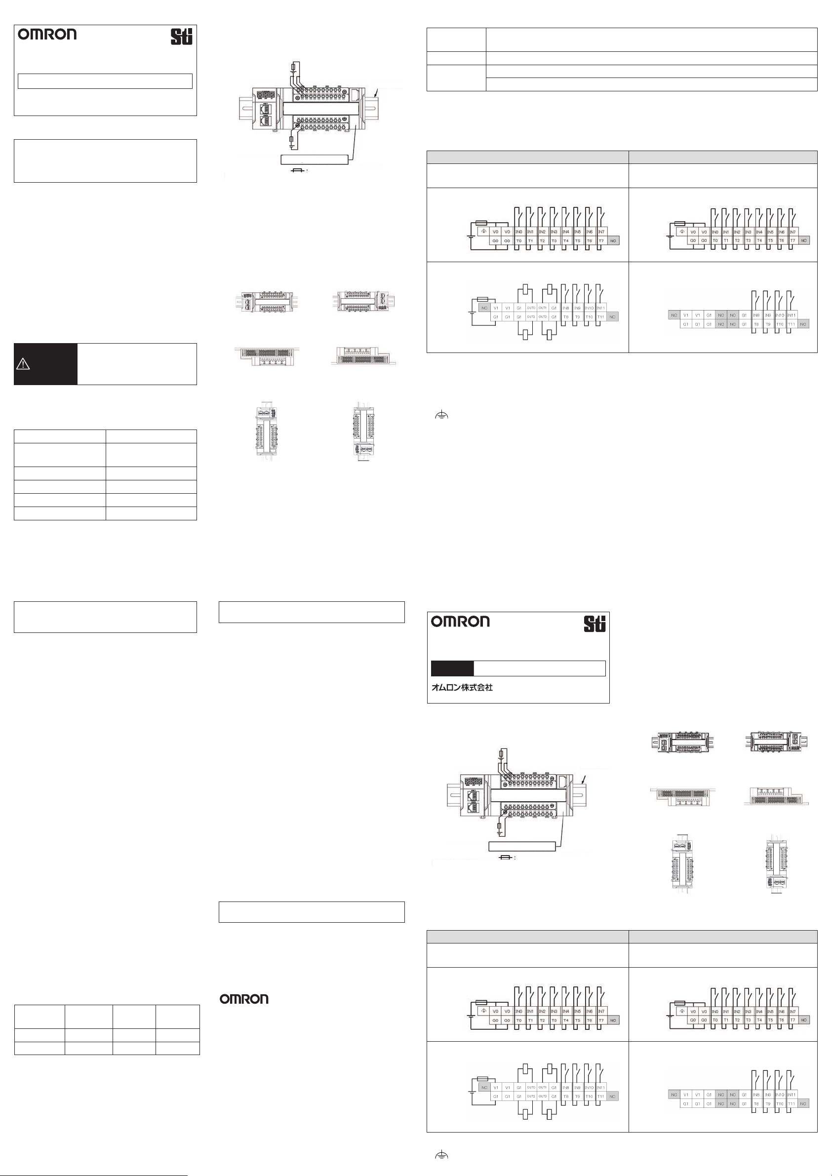
●I/O Wiring Diagram
GI-SMD1624
24 VDC input (12 point)
GI-SID1224
24 VDC input (12 point)
Sourcing Output (4 point)
Upper Terminal Block
Upper Terminal Block
24 VDC 24 VDC
Lower Terminal Block Lower Terminal Block
24 VDC
The input terminals (IN0-IN11) are not isolated from the internal circuit of the Safety I/O Terminal.
When the external devices are connected to the input terminals (IN0-IN11) of the Safety I/O Terminal, the power
of the external devices must be supplied from the Unit Power supply or Test output terminals (T0-T11).
●Marking
: Functional Earth Terminal
●Cleaning
Do not use paint thinner or similar chemical to
clean with. Use a dry cloth.
●Enclosure type
Please use this product in a control panel.
Enclosure type: Type 1 or more.
Conformance to UL Standards
and CSA Standards
Compliance with Class I Division 2
●
Hazardous Location:
Input and output wiring must be in accordance
with Class I, Div. 2 wiring methods and in
accordance with the authority having jurisdiction.
1. This equipment is suitable for use in Class I,
Div.2, Group A, B, C, D or Non-Hazardous
Locations Only.
2. WARNING : Explosion Hazard - Do not
Disconnect Equipment Unless Power Has
Been Switched off or the Area Is Known to Be
Non-Hazardous.
3. This device is open-type and is required to be
installed in an enclosure suitable for the
environment and can only be accessed with
the use of a tool or key.
1. Cet equipement convient a l'utilisation dans
des emplacements de Classe I, Division 2,
Groupes A, B, C, D, ou ne convient qu'a
l'utilisation dans des endroits non dangereux.
2. AVERTISSEMENT : Risque d'explosion Avant de debrancher l'equipement, couper le
courant ou s'assurer que l'emplacement est
designe non dangereux.
3. Ce dispositif est de type ouvert et doit etre
installe dans un coffret adapte a
l'environnement et auquel on ne pourra
acceder uniquement au moyen d'un outil ou
d'une cle.
T code: T4A
Conformance to EU Directives
This product is EMC-compliant when assembled in
PLC system or Machine Automation Controller.
To ensure the EU Directive conformance of
customer's machinery or equipment in which the
product is incorporated, be sure to observe the
following precautions.
1. This product is defined as an in-panel device and
must be installed within a control panel.
2. This product complies with the common emission
standard (EN61131-2, EN61000-6-4) with regard
to EMI. For the radiated emission requirement
(10-m regulations), in particular, please note that
the actual emission varies depending on the
configuration of the control panel to be used, the
connected devices, and wiring methods.
Therefore, the customer must confirm the EU
Directive conformance of the overall machinery or
equipment by themselves, even if this EU
conforming product is used.
This is a class A product. In residential areas it
may cause radio interference, in which case the
user may be required to take adequate measures
to reduce interference.
We have confirmed that this product conforms to
EMC standards with OMRON S8VS series Power
Supplies.
Conformance to KC Standards
●A급 기기업무용 방송통신기자재이
기기는업무용A급전자파적합기기로서
판매자 또는 사용자는 이 점을 주의하시기 바라며,
가정외의 지역에서 사용하는 것을 목적으로
합니다.
本書は英語オリジナル版の翻訳です。
GI-S
シリーズセーフティI/Oターミナル
形GI-S□□□□□□
JA
OMRON Corporation
©
取扱説明書
2018
All Rights Reserved.
4022169-1A
●電源コネクタからの電流に対する制限
外部電源はSELV要件を満たすDC電源を使用してくだ
さい。
ユニット電源
(SELV)
出力電源*
(SELV)
*形GI-SMD1624のみ
セーフティI/Oターミナル
過電流保護
(電流制限:F5A,DC24V以上)
次のカテゴリーのいずれかの
ヒューズを使用してください。
•cULus認証取得済み
•UL認証およびCSA認証取得済み
DINレール
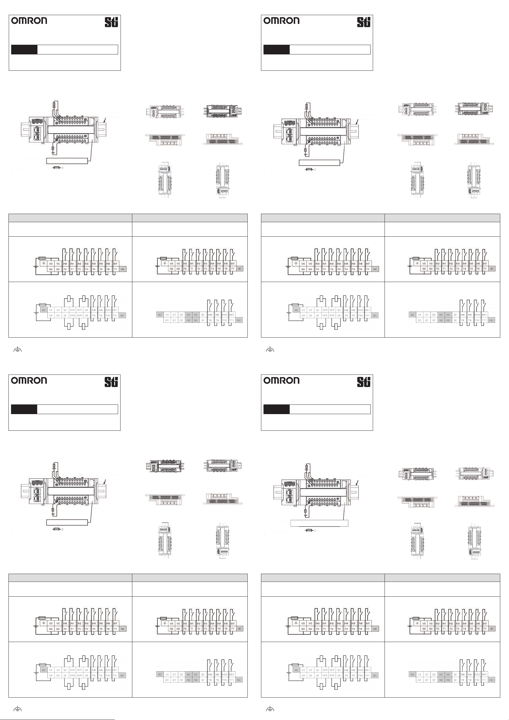
●I/O配線図
形GI-SMD1624
DC24V入力(12点)
ソース出力(4点)
上部端子台
セーフティI/Oターミナル形GI-SMD1624および
形GI-SID1224の欧州ユーザーへの通知
本マニュアルは、潜在的な危険およびその回避策を調べ
る際に必ず参照してください。
製造元の指定した方法に従わず機器を使用した場合、機
器の保護が損なわれることがあります。
この製品は盤内装置として定義されており、必ず制御盤
の中に設置してください。
●設置方向
この製品は下図の6方向に設置できます。
<縦>
<縦180°回転>
<横180°回転> <横>
<左上> <
右上
>
形GI-SID1224
DC24V入力(12点)
上部端子台
●Applicable wire size
Type Wire size Wire size
Conductor
surface
Solid/Strand AWG 28-16 9 mm Plated
Solid/Strand AWG 14* 11 mm Plated
*AWG 14 only use by Functional Earth Terminal.
Use Copper Conductors Only.
Do not use ferrule terminals. Insert the strand or
solid wire directly into the holes on the terminal
block.
Please select wire size suitable for rated current.
OMRON Corporation
Shiokoji Horikawa, Shimogyo-ku, Kyoto, 600-8530 Japan
Tel: (81)75-344-7109 Fax: (81)75-344-7149
Contact: www.ia.omron.com
Regional Headquarters
OMRON EUROPE B.V.
Wegalaan 67-69,2132 JD Hoofddorp,
Tel: (31)2356-81-300 Fax: (31)2356-81-388
OMRON ASIA PACIFIC PTE. LTD.
No. 438A Alexandra Road # 05-05/08 (Lobby 2), Alexandra Technopark,
Singapore 119967
Tel: (65) 6835-3011 Fax: (65) 6835-2711
OMRON ELECTRONICS LLC
2895 Greenspoint Parkway, Suite 200 Hoffman Estates, IL 60169 U.S.A.
Tel: (1) 847-843-7900 Fax: (1) 847-843-7787
OMRON (CHINA) CO., LTD.
Room 2211, Bank of China Tower, 200 Yin Cheng Zhong Road, Pu
Dong New Area, Shanghai, 200120, China
Tel: (86) 21-5037-2222 Fax: (86) 21-5037-2200
Note: Specifications subject to change without notice.
Printed in China
(Manufacturer)
(Importer in EU)
The Netherlands
DC24VDC24V
下部端子台下部端子台
DC24V
●記号
: 機能接地端子
Page 2
Übersetzung der Originalbetriebsanleitung
Hinweis für europäische Benutzer der
Sicherheits-E/V-Anschlüsse GI-SMD1624 und
GI-SID1224 der GI-Serie
Diese Anleitung muss stets herangezogen werden,
Sicherheits-E/V-Anschluss der GI-Serie
GI-S□□□□□□
DE
OMRON Corporation
OMRON Corporation
©
●
Strombeschränkungen des Stromversorgungssteckers
Die externen Stromversorgungen müssen
Gleichstromanschlüsse sein, die die
BEDIENUNGSANLEITUNG
2018
All Rights Reserved.
4022169-1A
um potentielle GEFAHREN sowie alle Maßnahmen,
die ergriffen werden müssen, um diese zu
vermeiden, in Erfahrung zu bringen.
Wird das Gerät auf eine Weise genutzt, wie sie nicht
vom Hersteller vorgesehen wurde, kann dies die
vom Gerät gebotene Sicherheit beeinträchtigen.
Bei diesem Produkt handelt es sich um ein
Einbauelement für Bedienpanels und muss als
solches in einem Bedienpanel installiert werden.
●Ausrichtung
SELV-Anforderungen erfüllen.
Leistung der Einheit
(SELV)
Ausgangsleistung*
(SELV)
*nur GI-SMD1624
Sicherheits-E/V-Anschluss
Überstromschutz
(Strombegrenzung:
F5A, 24 VDC min.)
Benutzen Sie Sicherungen
folgender Kategorien
• cULus Listed
• UL Listed und CSA certified
DIN-Schiene
<Horizontal, rotiert um 180°> <Horizontal>
●E/A-Verdrahtungsplan
GI-SMD1624
24 VDC Eingang (12 Punkte)
GI-SID1224
24 VDC Eingang (12 Punkte)
Aktiver Ausgang (4 Punkte)
Das Produkt kann in den folgenden sechs
Ausrichtungen installiert werden.
<Vertikal>
<Vertikal, rotiert um 180°>
<Linke Seite oben> <Rechte Seite oben>
Traduction de la notice
Remarques à l'attention des utilisateurs des
terminaux d'E/S de sécurité GI-SMD1624 et
GI-SID1224 en Europe.
Vous devez toujours vous référer à cette notice pour
Terminal d'E/S de sécurité de la série GI-S
GI-S□□□□□□
FR
OMRON Corporation
OMRON Corporation
©
●Limitation de courant par le connecteur
d'alimentation
Les alimentations externes doivent être des
alimentations CC qui répondent aux normes
FICHE D’INSTRUCTIONS
2018
All Rights Reserved.
4022169-1A
connaître la nature des DANGERS potentiels et les
mesures à prendre pour les éviter.
Toute utilisation de cet équipement non prévue par
le fabricant peut altérer la protection qu'il est sensé
procurer.
Ce produit a été conçu pour fonctionner à l'intérieur
d'un panneau de contrôle et doit donc y être installé.
●Sens d'installation
Le dispositif peut être installé dans les six
directions indiquées ci-dessous.
TBTS.
Puissance de l'unité
(TBTS)
Puissance de sortie*
(TBTS)
*Uniquement pour
GI-SMD1624
Terminal d'E/S de sécurité
Protection contre les surintensités
(limitation de courant :
F5A, 24 Vcc min.)
Utilisez des fusibles de l'une
des catégories suivantes
• homologués cULus
• homologués UL et certifiés CSA
RailDIN
<
Rotation horizontale de 180°
Avec le côté gauche v ers le haut><Avec le côté droit vers le haut
<
●Schéma de câblage E/S
GI-SMD1624
Entrée 24 Vcc (12 points)
GI-SID1224
Entrée 24 Vcc (12 points)
Sortie Source (4 points)
<Verticale>
<
Rotation verticale de 180°
> <Horizontale>
>
>
Oberer Anschlussblock
Oberer Anschlussblock
24 VDC 24 VDC
Unterer Anschlussblock Unterer Anschlussblock
24 VDC
●Symbol
: Funktionserdeanschluss
Traduzione delle istruzioni originali
Avviso agli utenti della serie GI di terminali I/O
di sicurezza GI-SMD1624 e GI-SID1224 in Europa
Queste istruzioni devono essere consultate in tutti i
Terminale I/O di sicurezza, serie GI-S
GI-S□□□□□□
IT
OMRON Corporation
OMRON Corporation
©
●Restrizioni della corrente dal connettore
all'alimentazione
Le alimentazioni esterne devono essere di tipo CC
e devono soddisfare i requisiti SELV.
Potenza unità
(SELV)
FOGLIO DI ISTRUZIONI
2018
All Rights Reserved.
4022169-1A
GuidaDIN
casi per poter individuare la natura dei RISCHI
potenziali e le azioni da intraprendere per evitarli.
Se l'attrezzatura è utilizzata in un modo non
specificato dal fabbricante, la protezione fornita con
l'attrezzatura potrebbe essere compromessa.
Questo prodotto è definito come un dispositivo
integrato nel pannello e deve essere installato
all'interno del pannello di controllo.
●Orientamento per l'installazione
Si può installare il prodotto nelle sei direzioni
descritte nell'immagine sottostante.
<Verticale>
Verticale ruotato di 180°
<
Bornier supérieur
24 Vcc 24 Vcc
Bornier inférieur Bornier inférieur
24 Vcc
●Symbole
: Borne de terre fonctionnelle
Traduccióndelmanualoriginal
Terminales de E/S de seguridad de la Serie GI-S
GI-S□□□□□□
ES
OMRON Corporation
OMRON Corporation
©
●Restricciones actuales del conector de
alimentación
Las fuentes de alimentación externas deben ser
fuentes de alimentación de CC que cumplan con
los requisitos de MBTS.
Unidad de alimentación
(MBTS)
>
HOJA DE INSTRUCCIONES
2018
All Rights Reserved.
4022169-1A
CarrilDIN
Bornier supérieur
Aviso a los usuarios del terminal de entrada y
salida de seguridad de la Serie GI-SMD1624 y
GI-SID1224 en Europa
Debe consultar estas instrucciones en todo
momento para conocer la naturaleza de los
posibles PELIGROS y saber qué medidas debe
tomar para evitarlos.
Si utiliza el equipo de una forma no especificada
por el fabricante, la protección proporcionada por el
equipo podría verse afectada.
Este producto es un dispositivo integrado en panel,
por lo que debe instalarse dentro de un panel de
control.
●Instrucciones de instalación
El producto se puede instalar en seis direcciones,
según la ilustración siguiente.
<Vertical>
Rotación vertical de 180°
<
>
Potenza d'uscita*
(SELV)
*solo GI-SMD1624
Terminale I/O di sicurezza
Protezione da sovracorrente
(Limitazione corrente:
F5A, 24 Vcc min.)
Utilizzare fusibili di una delle
seguenti categorie
• conformi cULus
• conformi UL e certificati CSA
<Orizzontale ruotato di 180°> <Orizzontale>
<Lato sinistro in alto> <Lato destro in alto>
●Schema elettrico I/O
GI-SMD1624
Ingresso 24 Vcc (12 punti)
GI-SID1224
Ingresso 24 Vcc (12 punti)
Uscita sourcing (4 punti)
Morsettiera superiore
Morsettiera superiore
24 Vcc 24 Vcc
Morsettiera inferiore Morsettiera inferiore
24 Vcc
Potencia de salida *
(MBTS)
*Solo GI-SMD1624
Terminal de entrada y salida de seguridad
Protección contra sobrecorriente
(limitación de corriente:
F5A, 24 V CC mín.)
Utilizar fusibles de cualquiera
de las siguientes categorías
• Estándar cULus
• Estándar UL y certificado CSA
●Cableado de entrada y salida
GI-SMD1624
Entrada de 24 V CC (12 puntos)
Rotación horizontal de 180°
<
Con el lado izquierdo hacia arriba
GI-SID1224
Entrada de 24 V CC (12 puntos)
> <Horizontal>
> <
<
Salida de suministro (4 puntos)
Regleta de conexiones superior
Regleta de conexiones superior
24 V CC 24 V CC
Regleta de conexiones inferior Regleta de conexiones inferior
24 V CC
Con el lado derecho hacia arriba
>
●Legenda
: Terminale di messa a terra
●Símbolo
:
Terminal de tierra funcional
 Loading...