

Page 1
USER'S GUIDE
G9SX
G9SX Flexible Safety Unit
G9SX-NS Non-Contact Door Switch Controller
G9SX-GS Safety Guard Switching Unit
Cat.No. Z255-E1-01
Page 2
2
G9SX
USER'S GUIDE
Introduction
This User’s Guide describes the usage of the G9SX Series-Flexible Safety Units mainly through application
examples.
Humans make mistakes and machines fail.
Therefore it is necessary to design machines and equipment based on the assumption that humans will make
mistakes and machines will fail.
Thus, a circuit configuration is required to ensure safety, even when an onsite operator makes a mistake in machine
operation or when a part of the machine fails. Flexible Safety Units, which enable various safety circuit patterns to be
configured only by simple wiring, provide the core components of such safety circuits.
Use the OMRON Flexible Safety Units in your machine and equipment to improve the safety designs and onsite
worker safety measures.
Outline of this User’s Guide
Section
1
Application Examples
Introduces applications that can be
configured with the G9SX.
Section
2
Functions of G9SX
Describes the functions of each unit of
G9SX Series.
Section
3
Wiring and Setup
Describes the wiring and settings
required for use.
Section
4
Ratings and Specifications
Provides specifications, dimensions and
terminal arrangements.
Appendix
Describes troubleshooting, accessories,
and related products.
Page 3
G9SX
USER'S GUIDE
3
Ordering Information
■ List of Models
Advanced Unit
Note: 1. The OFF-delay time can be set in 16 steps as follows:
T15: 0/0.2/0.3/0.4/0.5/0.6/0.7/1/1.5/2/3/4/5/7/10/15 s
T150: 0/10/20/30/40/50/60/70/80/90/100/110/120/130/140/150 s
2. The OFF-delayed output becomes an instantaneous output by setting the OFF-delay time to 0 s.
3. P channel MOS FET transistor output
4. PNP transistor output
Basic Unit
Note: 1. P channel MOS FET transistor output
2. PNP transistor output
Non-Contact Door Switch Controller (Controllers for D40A)
Note: 1. P channel MOS FET transistor output
2. The OFF-delayed output becomes an instantaneous output by setting the OFF-delay time to 0 s.
3. PNP transistor output
4. The OFF-delay time can be set in 16 steps as follows:
0/0.2/0.3/0.4/0.5/0.6/0.7/0.8/0.9/1.0/1.2/1.4/1.8/2.0/2.5/3.0 s
Safety Guard Switching Unit
Note: 1. The OFF-delay time can be set in 16 steps as follows:
T15: 0/0.2/0.3/0.4/0.5/0.6/0.7/1/1.5/2/3/4/5/7/10/15 s
2. The OFF-delayed output becomes an instantaneous output by setting the OFF-delay time to 0 s.
3. P channel MOS FET transistor output
4. PNP transistor output (except for the external indicator outputs, which are P channel MOS FET transistor outputs)
Expansion Unit
Note: 1. PNP transistor output
2.
The OFF-delay time is synchronized to the OFF-delay time setting in the connected Unit (G9SX-AD-@, G9SX-ADA-@, G9SX-NSA@ and G9SX-GS-@).
Safety outputs
(solid state) (See note 3.)
Auxiliary outputs
(solid state)
(See note 4.)
Logical AND connection
No. of input
channels
Max. OFF-
delay time
(See note 1.)
Rated
voltage
Terminal block type Model
Instantaneous
OFF-delayed
(See note 2.)
Inputs Outputs
3
(Semiconductor)
2
(Semiconductor)2(Semiconductor)
1
(Semiconductor)1(Semiconductor)
1 or 2
channels
15 s
24 VDC
Screw terminals G9SX-AD322-T15-RT
Spring-cage terminals G9SX-AD322-T15-RC
150 s
Screw terminals G9SX-AD322-T150-RT
Spring-cage terminals G9SX-AD322-T150-RC
2
(Semiconductor)
2
(Semiconductor)2(Semiconductor)
15 s
Screw terminals G9SX-ADA222-T15-RT
Spring-cage terminals G9SX-ADA222-T15-RC
150 s
Screw terminals G9SX-ADA222-T150-RT
Spring-cage terminals G9SX-ADA222-T150-RC
Safety outputs
(solid state) (See note 1.)
Auxiliary outputs
(solid state)
(See note 2.)
Logical AND
connection
No. of input
channels
Rated
voltage
Terminal block type Model
Instantaneous OFF-delayed Inputs Outputs
2
(Semiconductor)
---
2
(Semiconductor)
02
1 or 2
channels
24 VDC
Screw terminals G9SX-BC202-RT
Spring-cage terminals G9SX-BC202-RC
Safety outputs
(See note.1)
Auxiliary outputs
(See note 3.)
Logical AND
connection
input
Logical AND
connection
output
Max. OFF-
delay time
(See note 4.)
Rated
voltage
Terminal block type Model
Instantaneous
OFF-delayed
(See note 2.)
2
(Semiconductor)
0
2
(Semiconductor)
11
--24 VDC
Screw terminals G9SX-NS202-RT
Spring-cage terminals G9SX-NS202-RC
2
(Semiconductor)
3.0 s
Screw terminals G9SX-NSA222-T03-RT
Spring-cage terminals G9SX-NSA222-T03-RC
Safety outputs (See note 3.)
Auxiliary outputs
(See note 4.)
Logical AND connection
Max. OFF-
delay time
(See note 1.)
Rated
voltage
Terminal block
type
Model
Instantaneous
OFF-delayed
(See note 2.)
Inputs Outputs
2 (semiconductor) 2 (semiconductor) 6 (semiconductor) 1 (semiconductor) 1 (semiconductor) 15 s
24
VDC
Screw terminals G9SX-GS226-T15-RT
Spring-cage
terminals
G9SX-GS226-T15-RC
Safety outputs
Auxiliary outputs
(See note 1.)
OFF-delay time Rated voltage Terminal block type Model
Instantaneous OFF-delayed
4 PST-NO (contact) ---
1 (semiconductor)
--24 VDC
Screw terminals G9SX-EX401-RT
Spring-cage terminals G9SX-EX401-RC
--- 4 PST-NO (contact) (See note 2.)
Screw terminals G9SX-EX041-T-RT
Spring-cage terminals G9SX-EX041-T-RC
Page 4

4
G9SX
USER'S GUIDE
Model Number Structure
■ Model Number Legend
1. Functions
AD/ADA :Advanced Unit
BC :Basic Unit
GS :Safety Guard Switching Unit
NS/NSA :D40A Controller
EX :Expansion Unit
2. Output Configuration (Instantaneous Safety
Outputs)
0 : None
2 : 2 outputs
3 : 3 outputs
4 : 4 outputs
3. Output Configuration (OFF-delayed Safety
Outputs)
0 : None
2 : 2 outputs
4 : 4 outputs
4. Output Configuration (Auxiliary Outputs)
1 : 1 output
2 : 2 outputs
6 : 6 outputs
5. Max. OFF-delay Time
Advanced Unit
T15 : 15 s
T150 : 150 s
Basic Unit
No indicator : No OFF delay
Safety Guard Switching Unit
T15 : 15 s
D40A Controller
T03 : 3 s
Expansion Unit
No indicator : No OFF delay
T: OFF delay
6. Terminal Block Type
RT : Screw terminals
RC : Spring-cage terminals
1234 5 6
G9SX - @@@@@@ - @@@ - @@
Page 5
G9SX
USER'S GUIDE
5
CONTENTS
Section
1
Application Examples 7
1. Partial control of machine 8
1-1 Parts Processing Machine
8
1-2 Machining Center
11
1-3 Semiconductor Manufacturing Equipment
15
1-4 Machine Tool
17
2. Using Non-contact Door Switch 20
2-1 Pick and Place Machine
20
2-2 Small Assembly System
22
3. Coordinated operation of worker and
machine
25
3-1 Manufacturing Automotive Parts Using
Semi-automatic Processing
25
4. Safety Measures for limited operations 28
4-1 Manufacturing Flat-panel Displays
(Maintenance)
28
4-2 Machining Center (Enabling Switch)
31
4-3 LCD Manufacturing (Guard Lock Control)
34
Section
2
Functions of G9SX 37
1. Function list of G9SX-series 38
2. Functions of each Unit 39
2-1 Basic Unit
39
2-2 Advanced Unit
40
2-3 Non-Contact Door Switch Controller
42
2-4 Safety Guard Switching Unit
44
2-5 Expansion Unit
48
Page 6
CONTENTS
6
G9SX
USER'S GUIDE
Section
3
Wiring and Setup 51
1. I/O Terminals 52
1-1 Basic Unit
52
1-2 Advanced Unit
53
1-3 Non-contact Door Switch Controller
54
1-4 Safety Guard Switching Unit
55
1-5 Expansion Unit
56
2. Functions, Wiring and Settings 57
2-1 Logical AND Connection
57
2-2 Response Time and Operation Time
60
2-3 Reset Mode
62
2-4 Cross Fault Detection
63
2-5 Connecting Safety Sensors and the G9SX
64
2-6 OFF-delay Time
65
2-7 Non-contact Door Switch
66
2-8 Switching Mode
67
2-9 External Indicator Fault Diagnosis
68
2-10 Connecting Expansion Units
69
2-11 Confirming Settings
70
Section
4
Ratings and Specifications
71
1. Ratings 72
1-1 Advanced Unit/Basic Unit
72
1-2 Non-contact Door Switch Controller
73
1-3 Safety Guard Switching Unit
74
1-4 Expansion Unit
75
2. Characteristics 76
2-1 Advanced Unit/Basic Unit
76
2-2 Non-contact Door Switch Controller
77
2-3 Safety Guard Switching Unit
78
2-4 Expansion Unit
79
3. Dimensions and Terminal arrangements 80
3-1 Advanced Unit
80
3-2 Basic Unit
80
3-3 Non-contact Door Switch Controller
81
3-4 Safety Guard Switching Unit
81
3-5 Expansion Unit
82
Appendix 83
1. Troubleshooting
84
2. Logical AND Connections
91
3. Accessories and Related Products
93
Precautions 95
Page 7
G9SX
USER'S GUIDE
7
Application ExamplesSection 1
Section
1
Application Examples
1. Partial control of machine 8
1-1 Parts Processing Machine
8
1-2 Machining Center
11
1-3 Semiconductor Manufacturing Equipment
15
1-4 Machine Tool
17
2. Using Non-contact Door Switch 20
2-1 Pick and Place Machine
20
2-2 Small Assembly System
22
3. Coordinated operation of worker and
machine
25
3-1 Manufacturing Automotive Parts Using
Semi-automatic Processing
25
4. Safety Measures for limited operations 28
4-1 Manufacturing Flat-panel Displays
(Maintenance)
28
4-2 Machining Center (Enabling Switch)
31
4-3 LCD Manufacturing (Guard Lock Control)
34
Page 8
8
G9SX
USER'S GUIDE
Application ExamplesSection 1
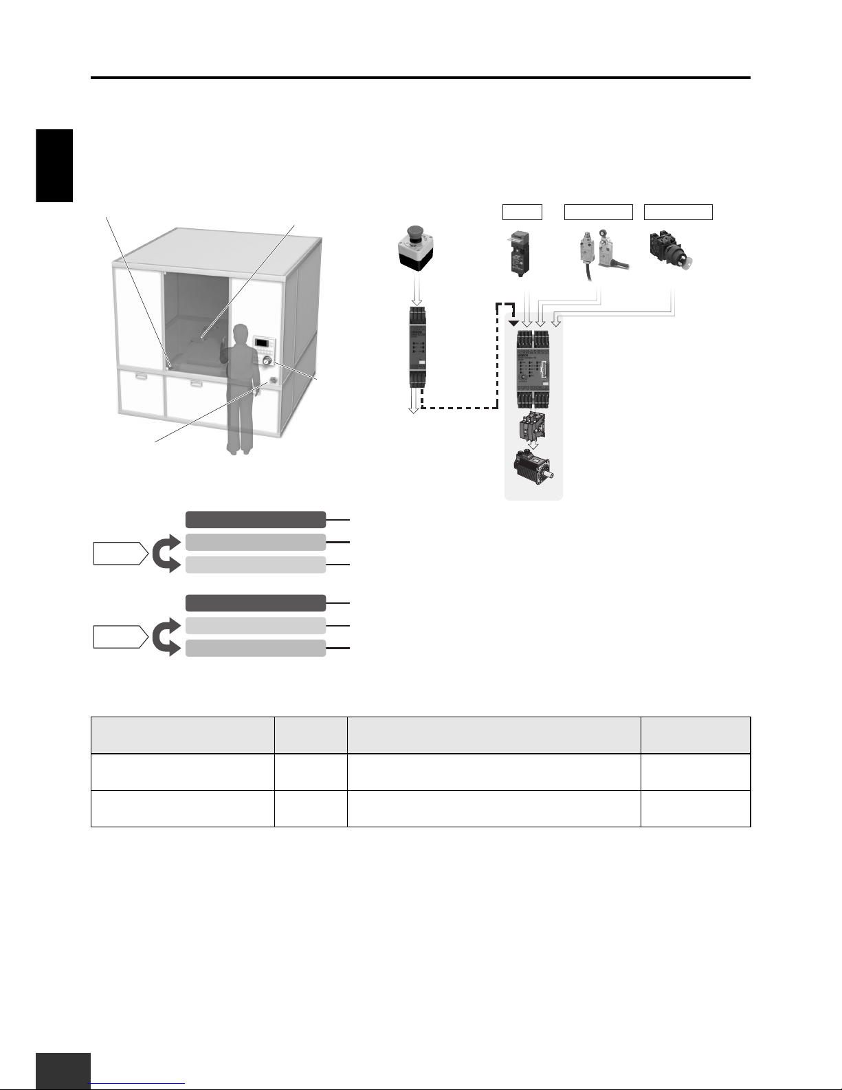
1. Partial control of machine
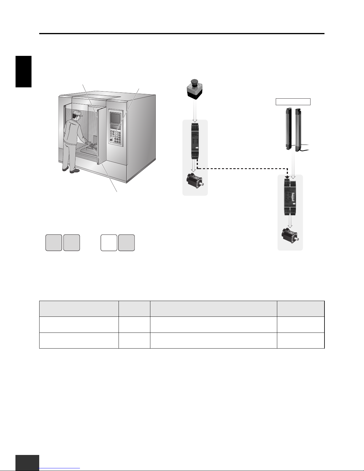
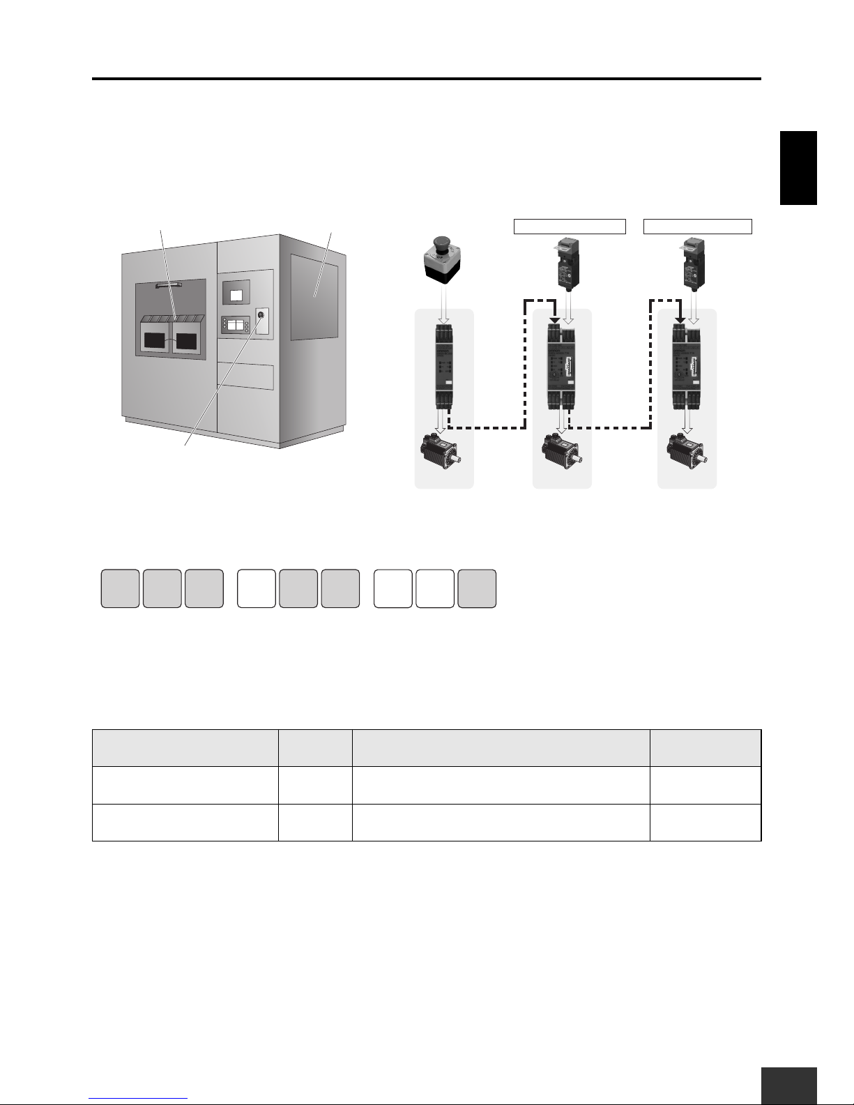
1-1 Parts Processing Machine
The entire device stops when the Emergency Stop Switch is pressed.
Only the processing section stops when the Safety Light Curtain is interrupted.
Required Units
Unit Qty. Safety input to be applied Page
G9SX-BC 1 Emergency Stop Switch 39
G9SX-AD 1 Safety Light Curtains 40
(2) Safety Light Curtain
Processing section
Stop
Segment A
Basic Unit
G9SX-BC
(1) Emergency Stop
Switch
(1) Emergency Stop
Switch
Segment B
(2) Safety Light
Curtain
Processing section
Advanced Unit
G9SX-AD
Segment A
Segment A Segment B
Stop Stop
Segment B
Stop
Operation Example
(2) Safety Light Curtain is
interrupted.
(1) The Emergency Stop Switch
is pressed.
Logical AND connection
Page 9
1. Partial control of machine
G9SX
USER'S GUIDE
9
Application ExamplesSection 1
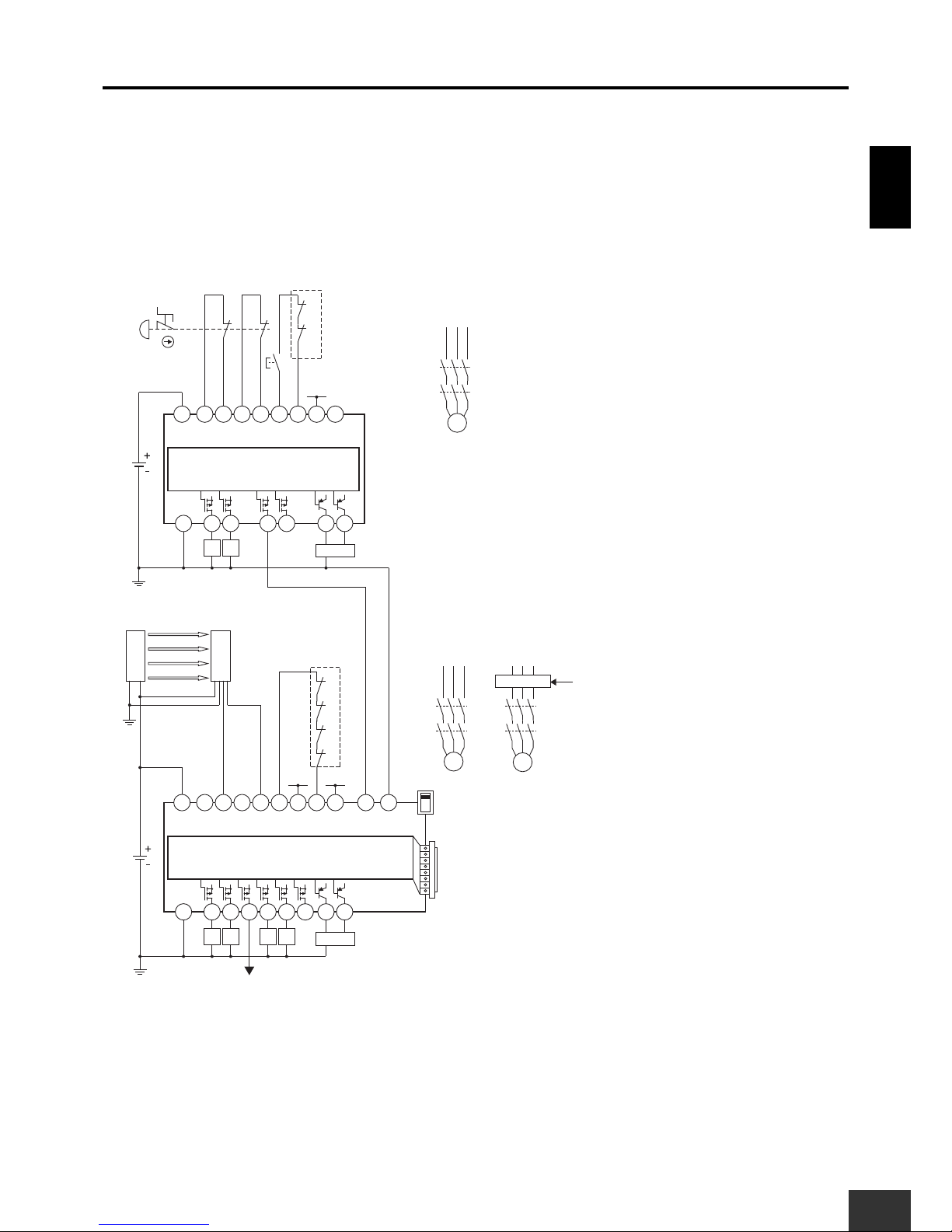
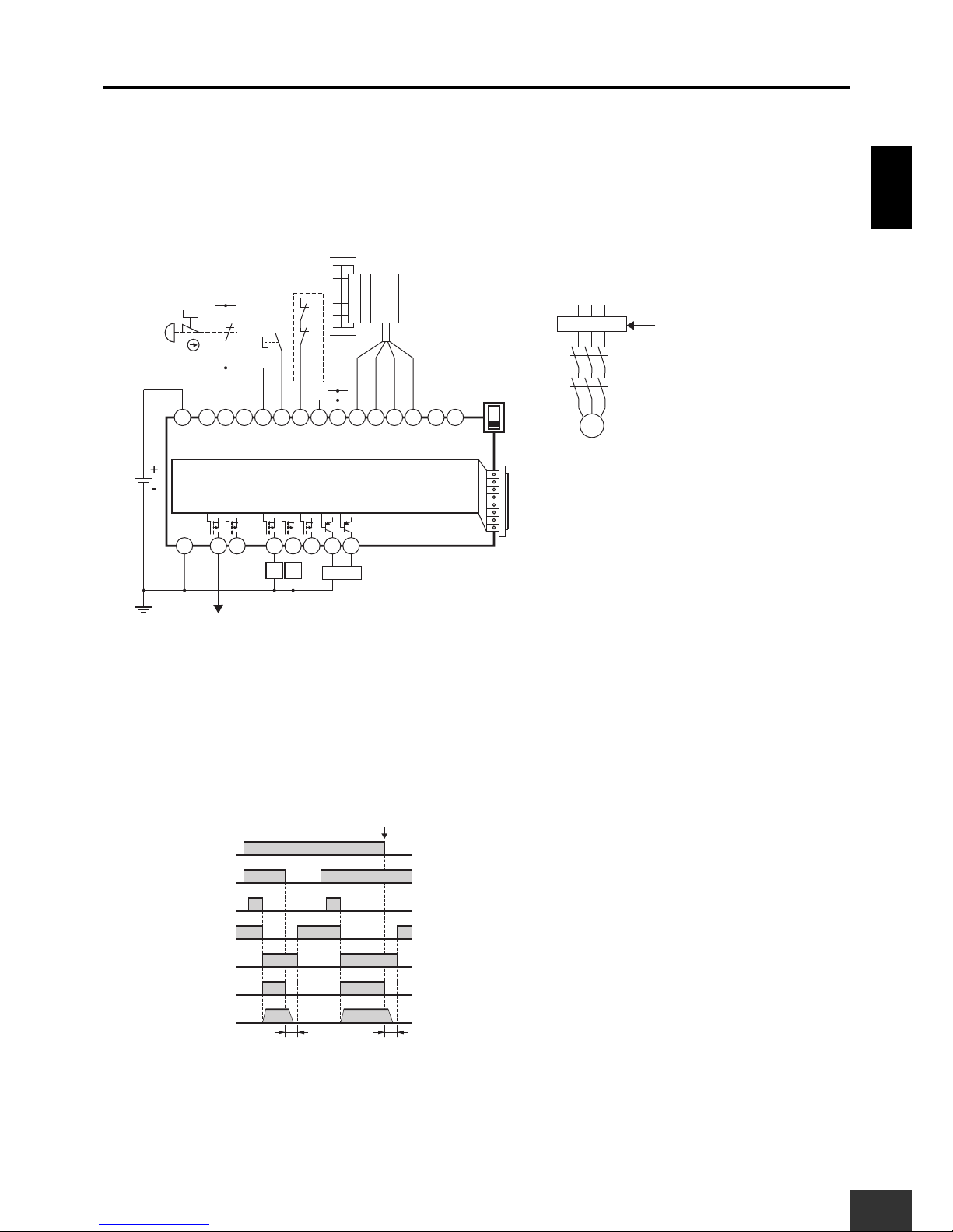
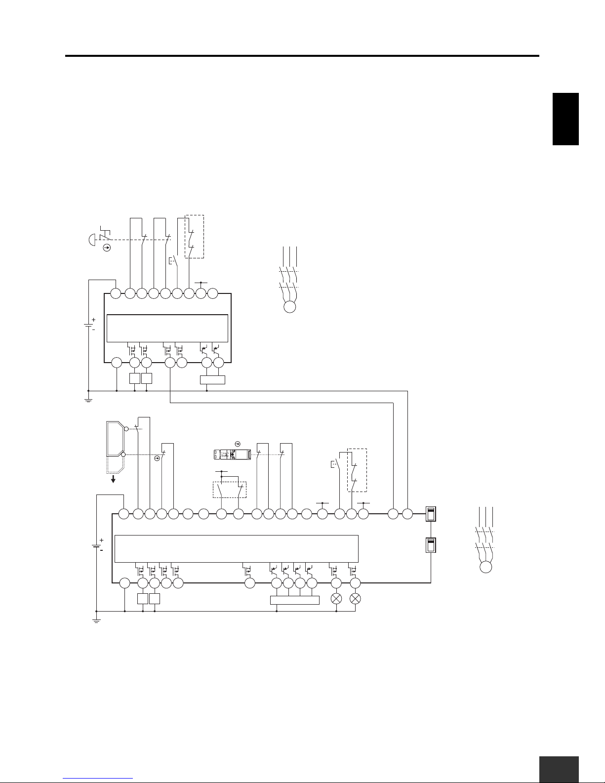
■ Wiring Example
Setup (For details, refer to Section 3.)
G9SX-BC: Manual reset, Cross fault detection mode: ON (Category 4 Wiring)
G9SX-AD: Auto reset, Cross fault detection mode: OFF (Category 4 Wiring (with Safety Light Curtains)),
Logical AND connections, OFF-delay time setting
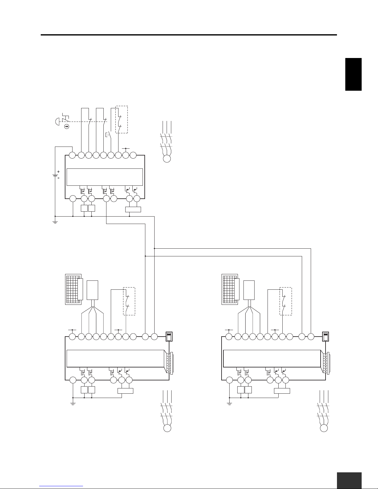
Wiring Example
Note: 1. This example corresponds to category 4. (when using a Type-4 Safety Sensor).
2. For further information on settings and wiring, refer to the datasheet or instruction sheet for the Safety Sensor.
3. Use Safety Sensors with PNP control outputs.
S14A2S24 S34 S44 S54
L1 X1 X2
T11A1T12 T21 T22 T31 T32 T33
Y1
T41 T42
S14A2S24 L1 L2
X1 X2
T11A1T12 T21 T22 T31 T32 T33
Y1
KM2
KM1
S2
12
11 21
22
+24V
+24V
KM1 KM2
M1
KM2
KM1
S1
+24V +24V
+24V
M2
KM4
KM3
S34
M3
KM6
KM5
OFF
NCNC
GND
G9SX-AD322-T15
Control circuit
G9SX-BC202
Control circuit
KM4
KM3
KM6
KM5
AND
KM3 KM4 KM5 KM6
Feedback Loop
NC
PLC etc.
Motor controller
Motor controller
(Operation command)
PLC etc.
Feedback Loop
F3SJ-A
GND
GND
ReceiverEmitter
Control output 1
Control output 2
S1 : Emergency Stop Switch
S2 : Reset switch
KM1 to KM6 : Contactor
M1 to M3 : 3-phase motor
Page 10
Application ExamplesSection 1
1. Partial control of machine
10
G9SX
USER'S GUIDE
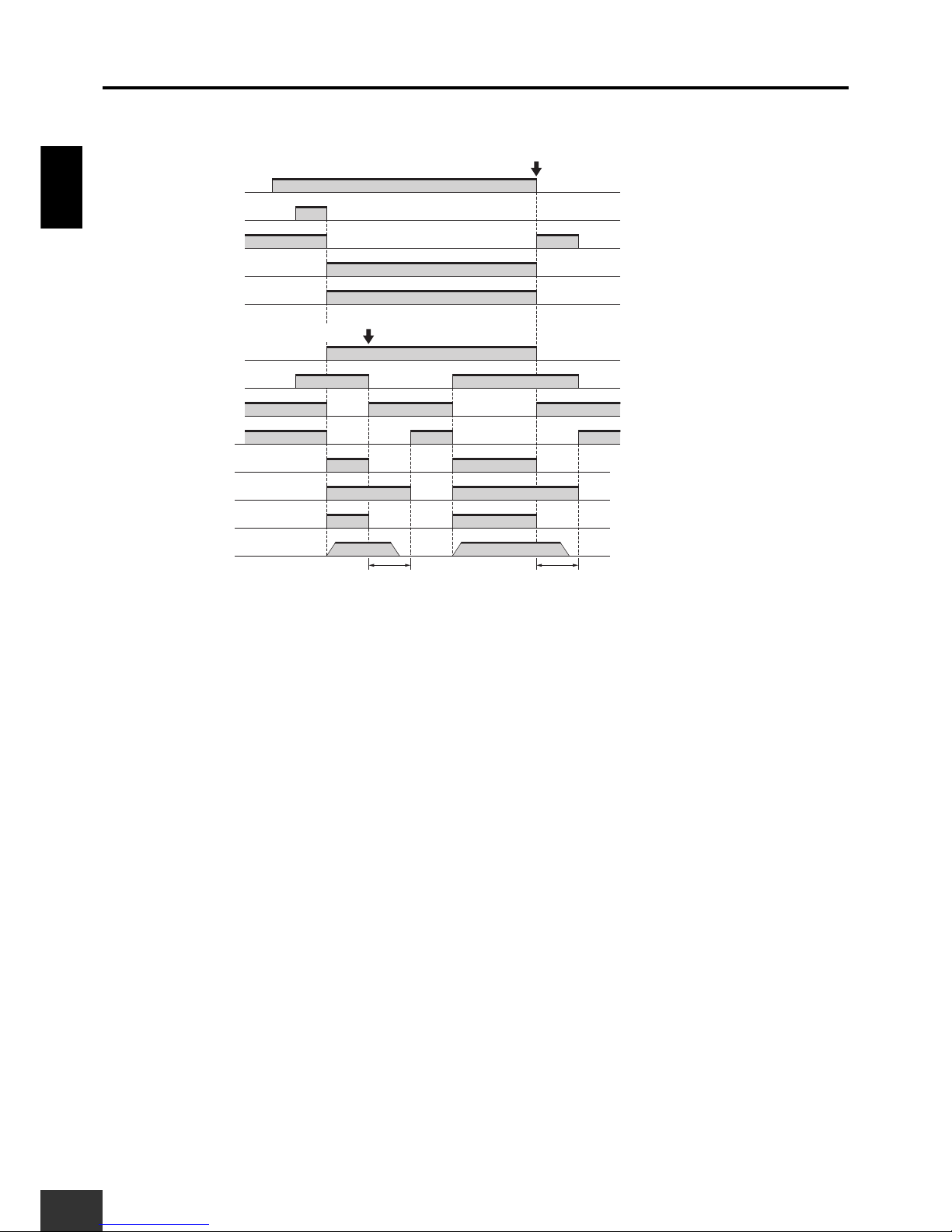
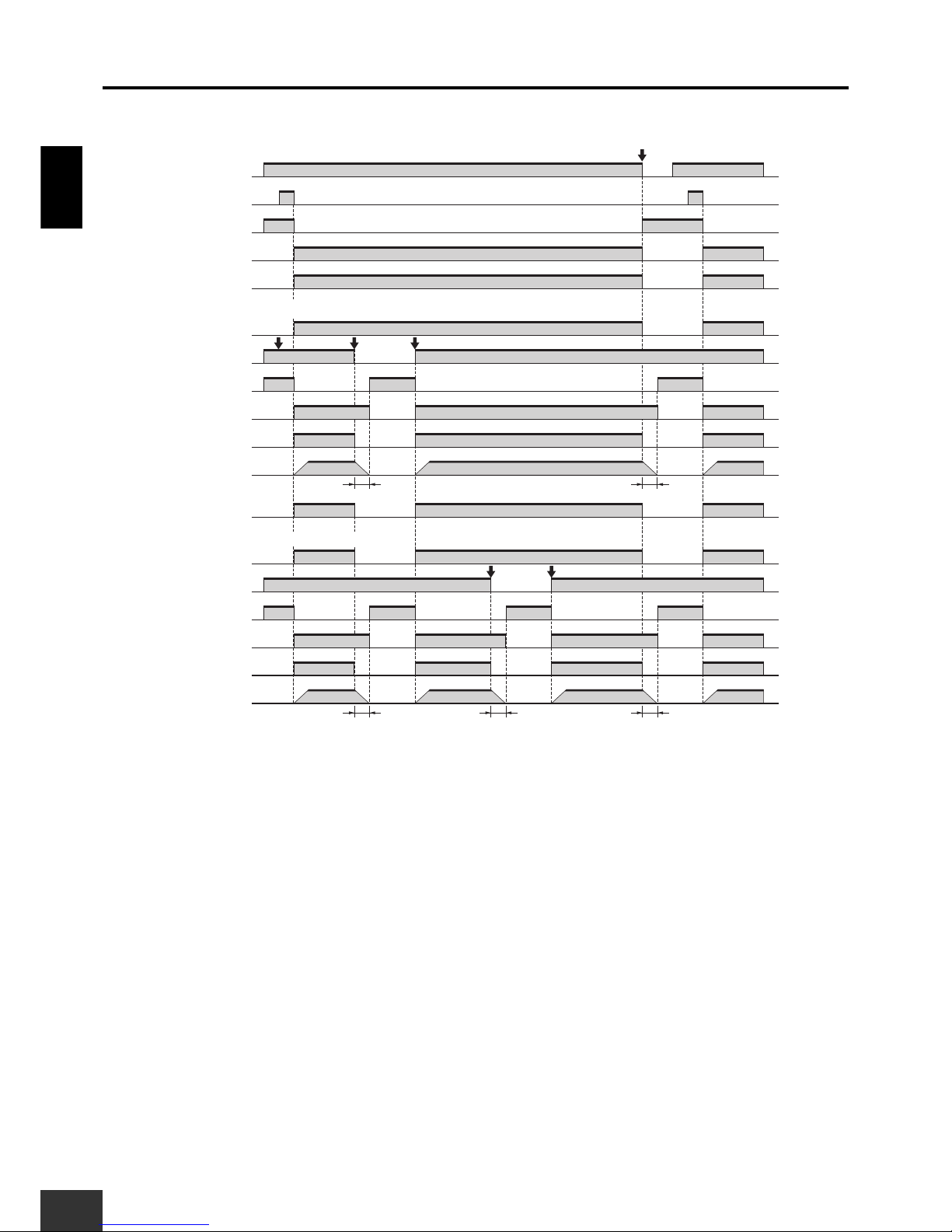
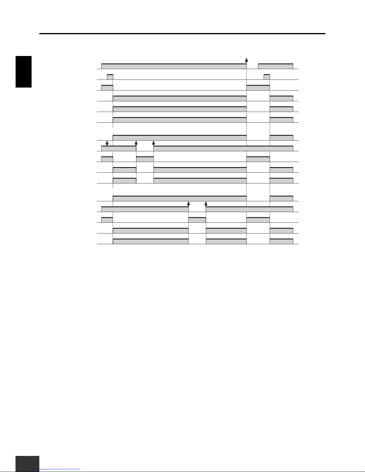
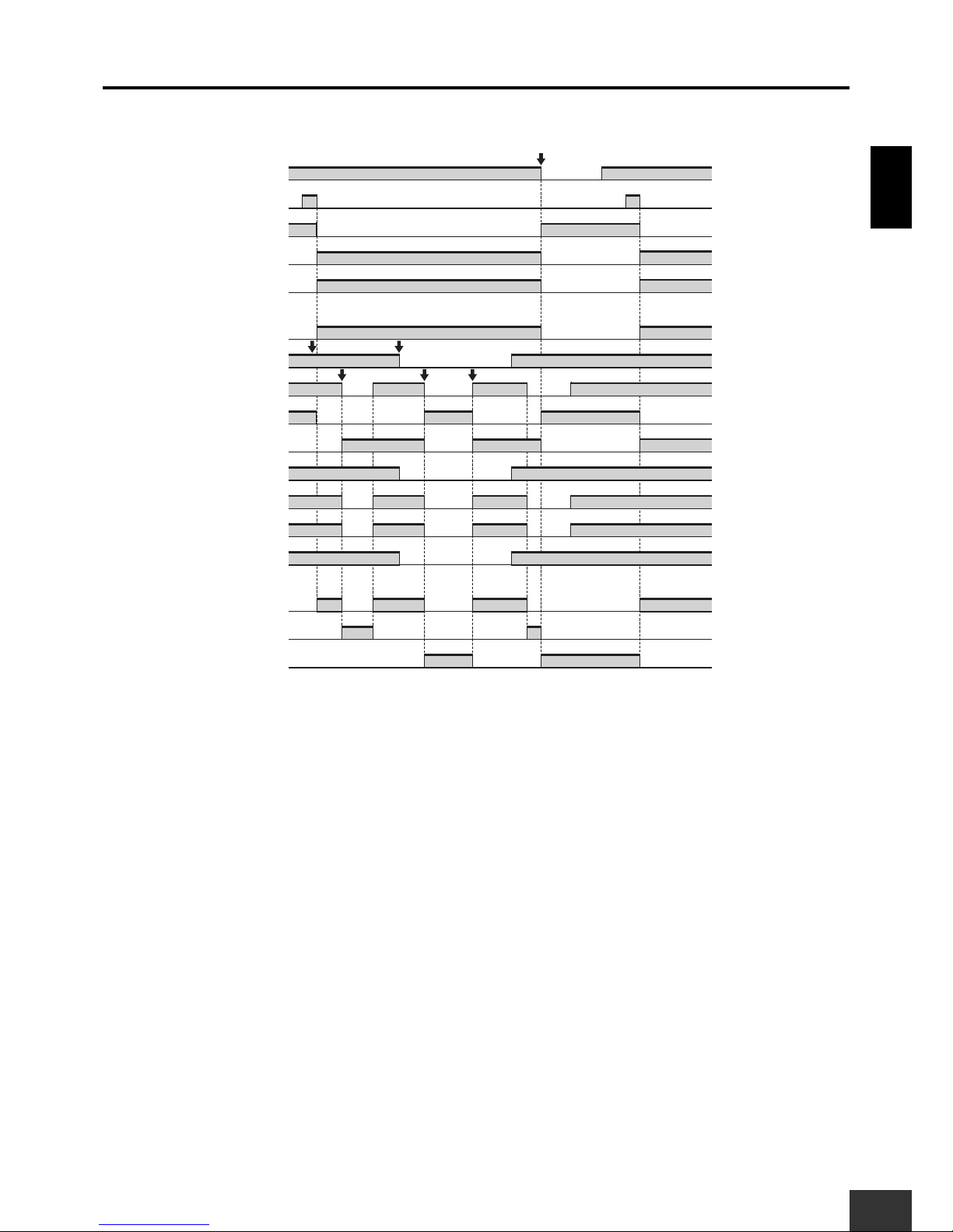
■ Timing chart
(1) Safety Light Curtain is interrupted: Only the lower Unit stops.
(2) Emergency stop button pressed: Both the upper and lower Unit stop.
G9SX-AD322-T15 (lower unit)
Reset switch S2
Emergency Stop Switch S1
KM1, KM2 NC contact
KM1, KM2 NO contact
Logical AND output L1
Logical AND input T41
Safety Light Curtain
Operation command
Rotation of motor
KM3, KM4 NC contact
KM5, KM6 NC contact
KM3, KM4 NO contact
KM5, KM6 NO contact
OFF-delay time OFF-delay time
G9SX-BC202 (upper unit)
(2)
(1)
Page 11
1. Partial control of machine
G9SX
USER'S GUIDE
11
Application ExamplesSection 1
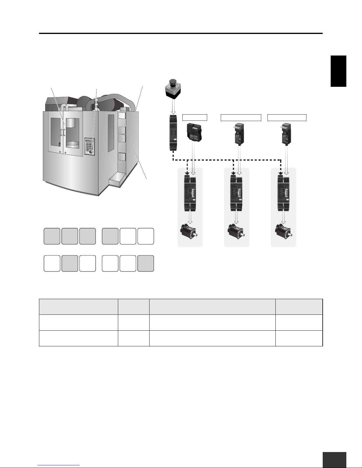
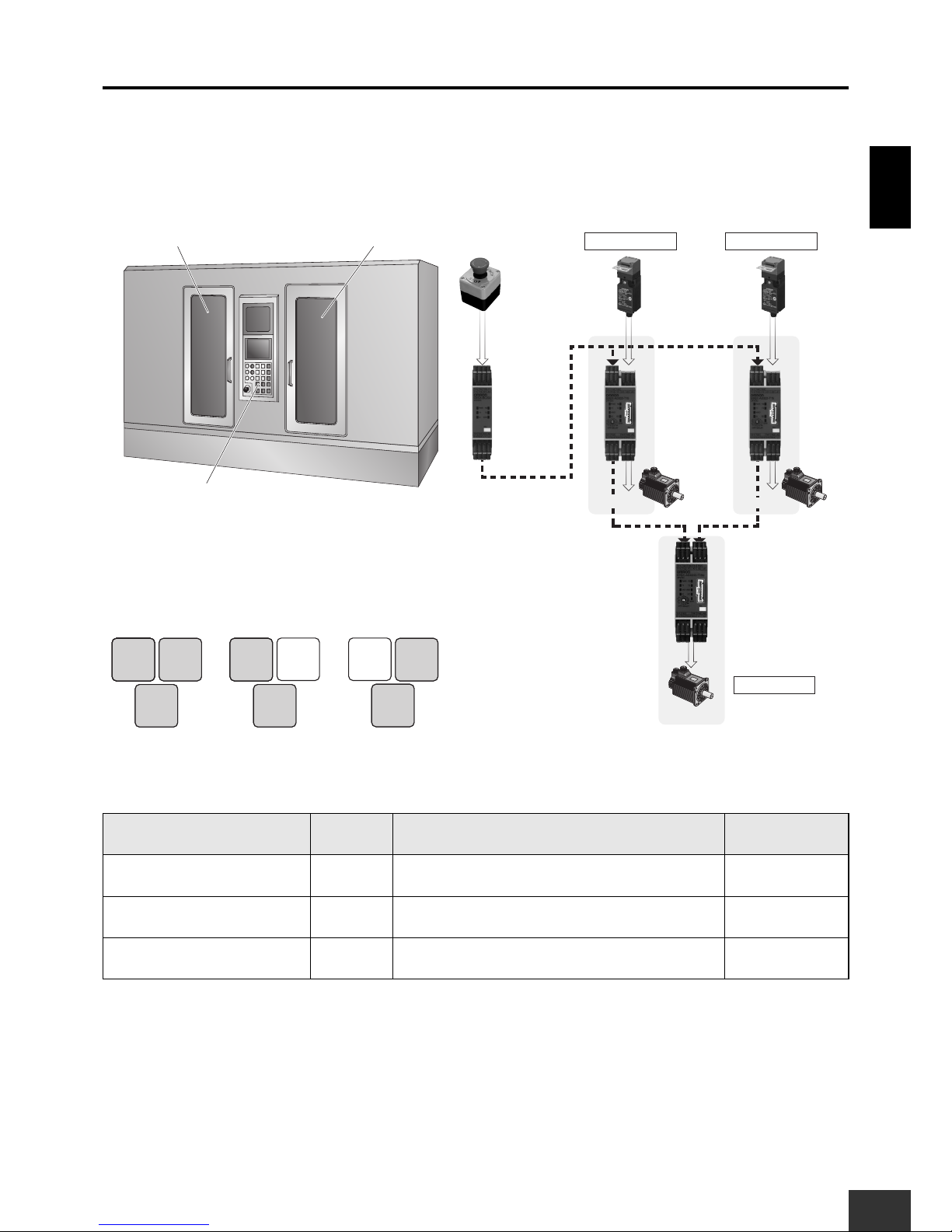
1-2 Machining Center
When the Emergency Stop Switch is pressed, the entire machine will stop.
When a door is open, the corresponding part will not be activated.
Required Units
Unit Qty. Safety input to be applied Page
G9SX-BC 1 Emergency Stop Switch 39
G9SX-AD 3
Guard Lock Safety Door Switch
Safety Door Switches (Set of two)
40
Segment A Segment B Segment C
(4) Tool changer door
(3) Pallet changer door
(1) Emergency Stop
Switch
(2) Main door
Segment A Segment B
(1) The Emergency Stop
Switch is pressed.
Stop Stop
Segment C
Stop
Segment A Segment B
(2) The main door is opened.
Stop Stop
Segment C
Stop
Segment A Segment B
(3) The pallet changer door
is opened.
Stop Stop
Segment C
Stop
Segment A Segment B
(4) The tool changer door is
opened.
Stop Stop
Segment C
Stop
Operation Example
Advanced Unit
G9SX-AD
Advanced Unit
G9SX-AD
Advanced Unit
G9SX-AD
(3) Pallet Changer Door (4) Tool Changer Door
Safety Door
Switch
Safety Door
Switch
Basic Unit
G9SX-BC
(2) Main Door
Logical AND connection
(1) Emergency Stop
Switch
Guard Lock
Safety Door
Switch
Page 12
Application ExamplesSection 1
1. Partial control of machine
12
G9SX
USER'S GUIDE
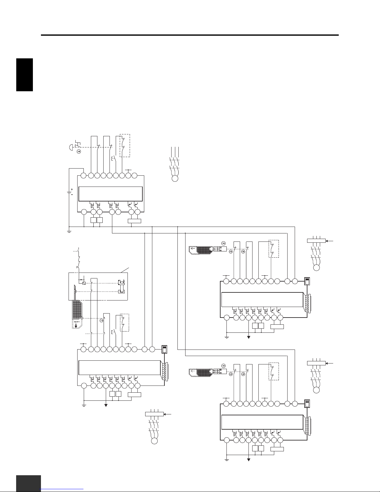
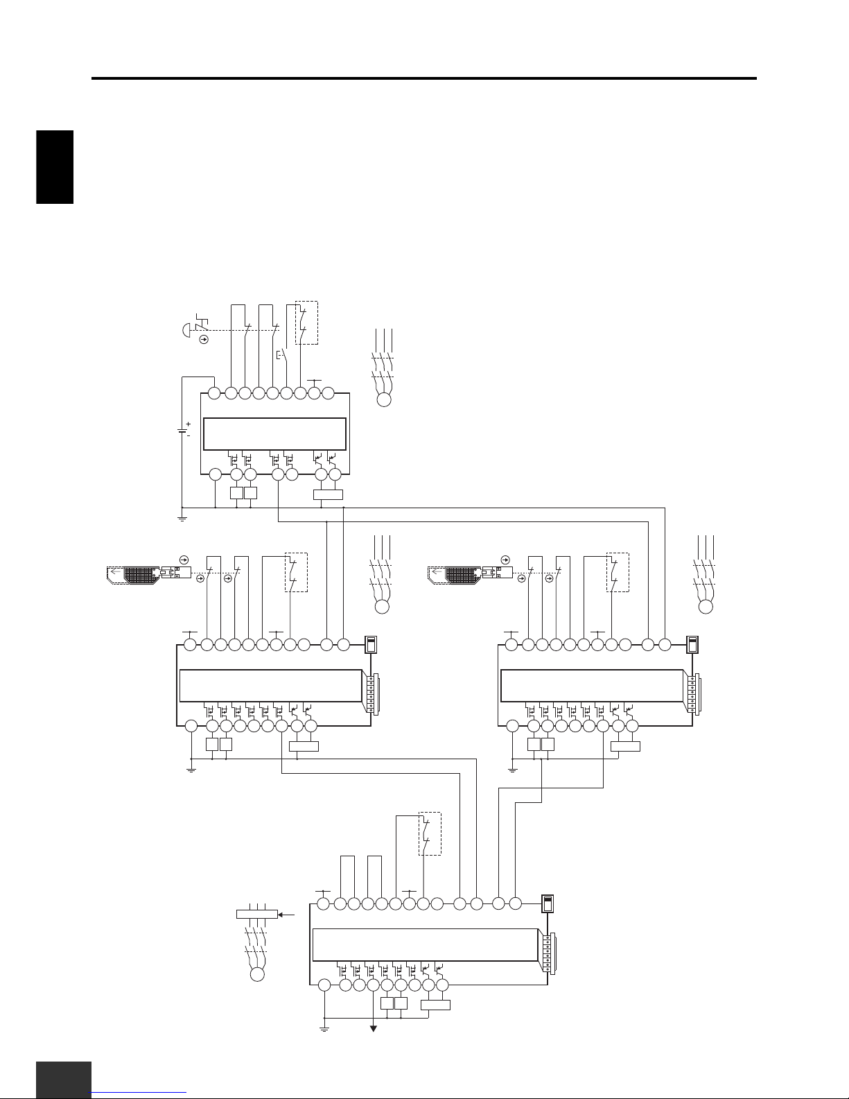
■ Wiring Example
Setup (For details, refer to Section 3.)
G9SX-BC: Manual reset, Cross fault detection mode: ON (Category 4 Wiring)
G9SX-AD (main door section): Manual reset, Cross fault detection mode: ON (Category 4 Wiring),
Logical AND connections, OFF-delay time setting
G9SX-AD (pallet changer, tool changer): Auto reset, Cross fault detection mode: ON (Category 4 Wiring),
Logical AND connections, OFF-delay time setting
Wiring Example
PLC etc.
PLC etc.
PLC etc.
S14A2S24 S34 S44 S54
L1 X1 X2
T11A1T12 T21 T22 T31 T32 T33Y1T41 T42
S14A2S24 L1 L2
X1 X2
T11A1T12 T21 T22 T31 T32 T33
Y1
KM2
KM1
S2
S6
12
11 21
22
+24V
KM1 KM2
M1
KM2
KM1
S1
+24V
KM3 KM4
S344
M2
KM4
KM3
Motor controller
S344
M4
KM8
KM7
S344
M3
KM6
KM5
OFF
AND
S8
Open
S7
NC
NC
Feedback Loop
Lock release signal
GND
GND
G9SX-AD322-T15 (Main door)
Control circuit
G9SX-BC202
Control circuit
Feedback Loop
S14A2S24 S34 S44 S54
L1 X1 X2
T11A1T12 T21 T22 T31 T32 T33Y1T41 T42
+24V
+24V
+24V+24V
OFF
AND
NC
GND
G9SX-AD322-T15 (Tool changer door)
Control circuit
KM8
KM7
PLC etc.
Feedback Loop
S14A2S24 S34 S44 S54
L1 X1 X2
T11A1T12 T21 T22 T31 T32 T33Y1T41 T42
+24V
+24V
KM5 KM6
OFF
AND
NC
GND
G9SX-AD322-T15
(Pallet changer door)
Control circuit
KM6
KM5
S4
Feedback Loop
KM3
KM4
41
42
12
11
S5
KM4
KM3
S3
Open
KM7 KM8
Motor controller
(Operation command)
Motor controller
(Operation command)
Motor controller
(Operation command)
Motor controller
Motor controller
Stop signal
Guard
S1 : Emergency Stop Switch
S2, S6 : Reset switch
S3 : Guard Lock Safety Door Switch
S4 : Safety Limit Switch
S5 : Lock release switch
S7, S8 : Safety Door Switch
KM1 to KM8 : Contactor
M1 to M4 : 3-phase motor
Note: This example corresponds to category 4.
Page 13
1. Partial control of machine
G9SX
USER'S GUIDE
13
Application ExamplesSection 1
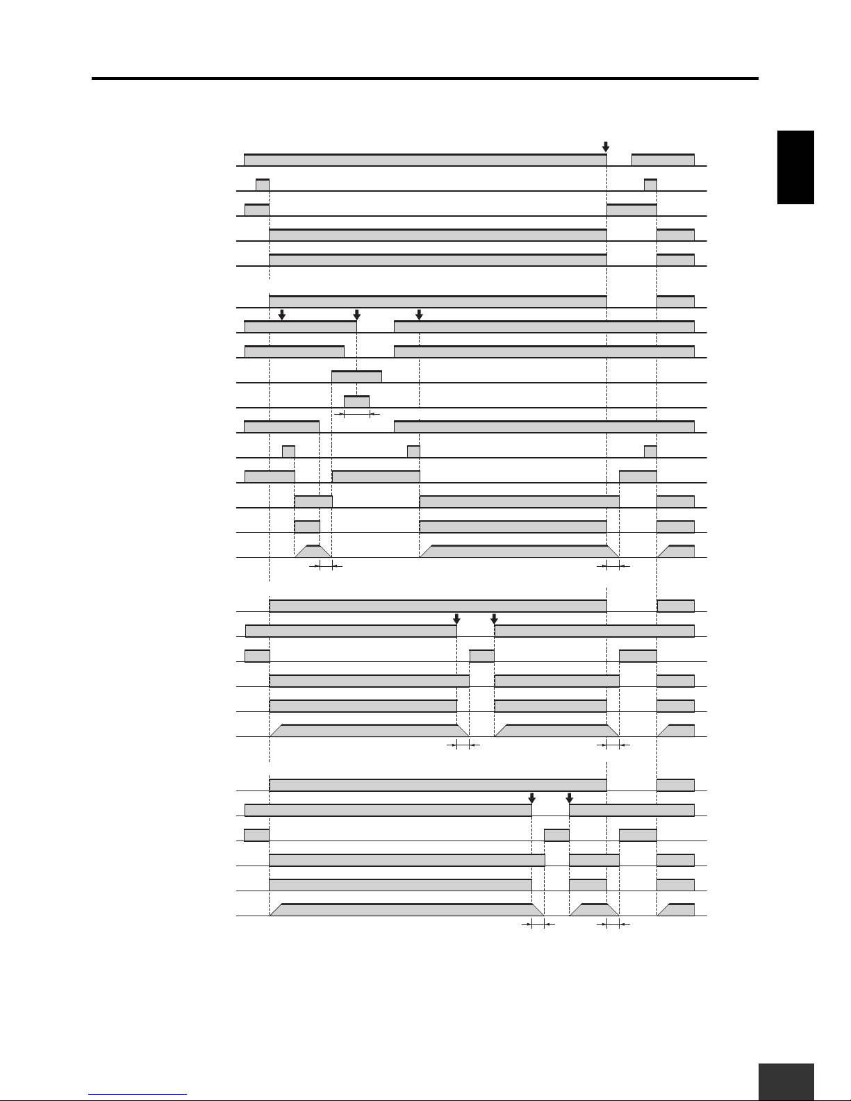
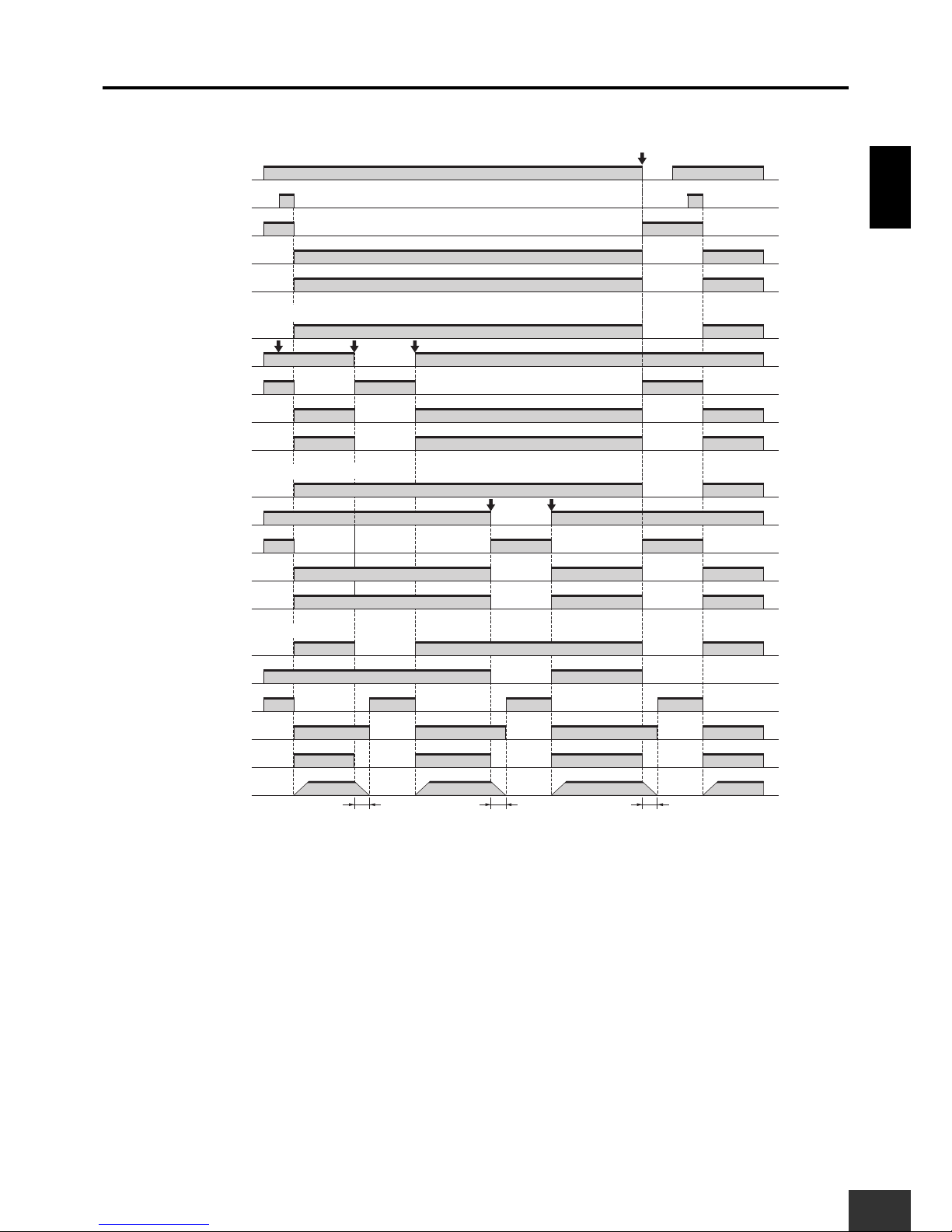
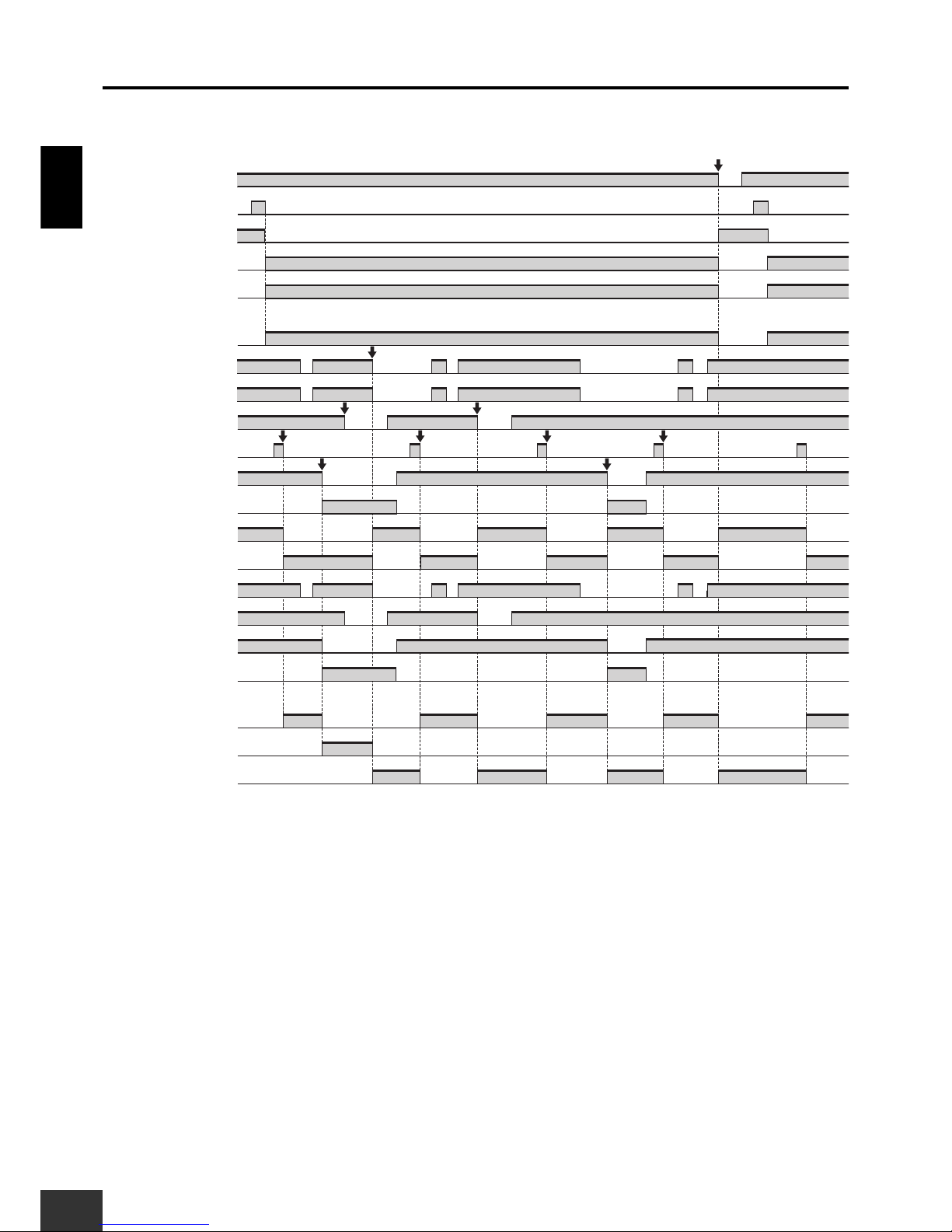
■ Timing chart
(1) Before operation is started.
(2) Main door is unlocked and opened, and then work is performed.
(3) Restart operation after the main door is closed.
(4) The pallet changer door opens and the pallet changer section stops.
(5) The pallet changer door is closed and the pallet changer is reset.
(6) The tool changer door opens and the tool changer section stops.
(7) The tool changer door is closed and the tool changer section is reset.
(8) If the Emergency Stop Switch is pressed, the upper unit and lower units will stop.
Emergency Stop Switch S1
Reset switch S2
Logical AND output L1
KM1, KM2 NC contact
KM1, KM2 NO contact
Logical AND input T41
Logical AND input T41
Logical AND input T41
KM3, KM4 NC contact
KM3, KM4 NO contact
Safety Limit Switch S4
Safety Door Switch S7
Safety Door Switch S8
Reset switch S6
Operation command
Rotation of motor
Operation command
Rotation of motor
Operation command
Rotation of motor
OFF-delay time
OFF-delay time
OFF-delay time OFF-delay time
OFF-delay time OFF-delay time
Door can be opened.
Stop signal
Lock release signal
Lock release switch S5
Guard Lock Safety Door Switch S3
(1) (2) (3)
(8)
(4) (5)
(6) (7)
G9SX-BC202 (upper unit)
KM5, KM6, NC contact
KM5, KM6, NO contact
KM7, KM8, NC contact
KM7, KM8, NO contact
G9SX-AD322-T15 (lower unit : Main door)
G9SX-AD322-T15 (lower unit : Pallet changer door)
G9SX-AD322-T15 (lower unit : Tool changer door)
Page 14
Application ExamplesSection 1
1. Partial control of machine
14
G9SX
USER'S GUIDE
■ Timing chart
(1) Before operation is started.
(2) The processing section cover is opened, and the processing section and the conveyor section stops.
(3) The processing section cover is closed and the processing section and conveyor section restart.
(4) The conveyor section cover is opened and the conveyor section stops.
(5) The transport section cover is closed and the conveyor section restarts.
(6) If the Emergency Stop Switch is pressed, unit A, unit B, and unit C will stop.
G9SX-BC202 (Unit A)
G9SX-AD322-T15 (Unit B:Processing section cover)
G9SX-AD322-T15 (Unit C:Conveyor section cover)
Emergency Stop Switch S1
Reset switch S2
Logical AND output L1
KM1, KM2 NC contact
KM1, KM2 NO contact
KM3, KM4 NC contact
KM3, KM4 NO contact
Operation command
Rotation of motor
Logical AND input T41
Operation command
Rotation of motor
KM5, KM6, NC contact
KM5, KM6, NO contact
Logical AND input T41
Safety Door Switch S4
Safety Door Switch S3
OFF-delay time
OFF-delay time OFF-delay time
OFF-delay timeOFF-delay time
(4)
(3)
(6)
(2)(1)
(5)
Logical AND output L1
Page 15
1. Partial control of machine
G9SX
USER'S GUIDE
15
Application ExamplesSection 1
1-3 Semiconductor Manufacturing Equipment
When the Emergency Stop Switch is pressed, all of the equipment stops.
When the processing section cover is opened, the processing section and conveyor section stop.
When the conveyor section cover is opened, only the conveyor section stops.
Required Units
Unit Qty. Safety input to be applied Page
G9SX-BC 1 Emergency Stop Switch 39
G9SX-AD 2 Safety Door Switches (Set of two) 40
Logical AND
connection
Safety Door
Switch
Safety Door
Switch
Advanced Unit
G9SX-AD
Advanced Unit
G9SX-AD
Segment CSegment B
Basic Unit
G9SX-BC
Logical AND
connection
(1) Emergency Stop
Switch
Segment A
(3) The conveyor section
cover is opened.
(1) The Emergency Stop
Switch is pressed.
(2) The
processing section
cover is opened.
Operation Example
(2) Processing section cover (3) Conveyor section cover
(1) Emergency Stop
Switch
(2) Processing
section cover
(3) Conveyor
section cover
Segment A Segment B Segment C
Stop
Segment A Segment B
Stop Stop
Segment C
Stop
Segment A
Segment B
Stop
Segment C
Stop
Page 16

Application ExamplesSection 1
1. Partial control of machine
16
G9SX
USER'S GUIDE
■ Wiring Example
Setup (For details, refer to Section 3.)
G9SX-BC: Manual reset, Cross fault detection mode: ON (Category 4 Wiring)
G9SX-AD: Auto reset, Cross fault detection mode: ON (Category 4 Wiring), Logical AND connections,
OFF-delay time setting
Wiring Example
S14A2S24 L1 L2
X1 X2
T11A1T12 T21 T22 T31 T32 T33
Y1
KM2
KM1
S2
12
11 21
22
+24V
M1
KM2
KM1
S1
+24V
NC
GND
G9SX-BC202 (Unit A)
Control circuit
S344
M3
KM6
KM5
Open
S4
Feedback Loop
S14A2S24 S34 S44 S54
L1 X1 X2
T11A1T12 T21 T22 T31 T32 T33Y1T41 T42
+24V
+24V
KM5 KM6
OFF
AND
NC
GND
G9SX-AD322-T15 (Unit C)
Control circuit
KM6
KM5
Motor controller
Motor controller
S344
M2
KM4
KM3
Open
S3
PLC etc.
Feedback Loop
S14A2S24 S34 S44 S54
L1 X1 X2
T11A1T12 T21 T22 T31 T32 T33Y1T41 T42
+24V
+24V
KM3 KM4
OFF
AND
NC
GND
G9SX-AD322-T15 (Unit B)
Control circuit
KM4
KM3
Feedback Loop
KM1 KM2
Motor controller
(Operation command)
Motor controller
(Operation command)
PLC etc.
PLC etc.
S1 : Emergency Stop Switch
S2 : Reset switch
S3, S4 : Safety Door Switch
KM1 to KM6 : Contactor
M1 to M3 : 3-phase motor
Note: This example corresponds to category 4.
Page 17
1. Partial control of machine
G9SX
USER'S GUIDE
17
Application ExamplesSection 1
1-4 Machine Tool
When the Emergency Stop Switch is pressed, the entire machine will stop.
If the left door is opened, the left drive section and transport section will stop.
If the right door is opened, the right drive section and transport section will stop.
Required Units
Unit Qty. Safety input to be applied Page
G9SX-BC 1 Emergency Stop Switch 39
G9SX-AD 2 Safety Door Switches (Set of two) 40
G9SX-ADA 1 --- 41
Safety Door
Switch
Advanced Unit
G9SX-AD
Advanced Unit
G9SX-AD
(2) Left door (3) Right door
Safety Door
Switch
Segment A Segment B
Segment C
Advanced Unit
G9SX-ADA
Logical AND
connection
Logical AND
connection
Logical AND
connection
Transport section
Basic Unit
G9SX-BC
(1) Emergency Stop
Switch
(2) Left door (3) Right door
(1) The Emergency Stop
Switch is pressed.
(2) The left door is opened.
(3) The right door is opened.
Operation Example
(1) Emergency Stop
Switch
Segment A
Stop
Segment A
Stop
Segment A
Stop
Segment A
Stop
Segment A
Stop
Segment A
Stop
Segment A
Stop
Segment A
Stop
Segment A
Stop
Segment A
Stop
Segment A
Stop
Segment A
Stop
Segment A
Stop
Segment B
Stop
Segment A
Stop
Segment C
Stop
Segment A
Stop
Segment B
Stop
Segment A
Stop
Segment C
Stop
Segment A
Stop
Segment C
Stop
Segment A
Stop
Segment B
Stop
Page 18
Application ExamplesSection 1
1. Partial control of machine
18
G9SX
USER'S GUIDE
■ Wiring Example
Setup (For details, refer to Section 3.)
G9SX-BC: Manual reset, Cross fault detection mode: ON (Category 4 Wiring)
G9SX-AD: Auto reset, Cross fault detection mode: ON (Category 4 Wiring), Logical AND connections,
No OFF-delay time setting
G9SX-ADA: Auto reset, Cross fault detection mode: ON (Category 4 Wiring), Logical AND connections,
OFF-delay time setting
Wiring Example
PLC etc.
S14A2S24 L1 L2
X1 X2
T11A1T12 T21 T22 T31 T32 T33
Y1
KM2
KM1
S2
12
11 21
22
+24V
KM1 KM2
M1
KM2
KM1
S1
+24V
NC
GND
G9SX-BC202
Feedback Loop
Open
S3
PLC etc.
Feedback Loop
S14A2S24 S34 S44 S54
L1 X1 X2
T11A1T12 T21 T22 T31 T32 T33Y1T41 T42
+24V
+24V
KM3 KM4
OFF
AND
Left drive section
Transport section
Right drive section
NC
GND
G9SX-AD322-T15 (Left door)
Control circuit
KM4
KM3
M3
KM6
KM5
M2
KM4
KM3
Open
S4
PLC etc.
Feedback Loop
S14A2S24 S34 S44 S54
L1 X1 X2
T11A1T12 T21 T22 T31 T32 T33Y1T41 T42
+24V
+24V
KM5 KM6
OFF
AND
NC
GND
G9SX-AD322-T15 (Right door)
Control circuit
KM6
KM5
PLC etc.
Motor controller
S344
M4
KM8
KM7
G9SX-ADA222-T150
S14A2S24 S44 S54
L1 X1
S34
X2
T11A1T12 T21 T22 T31 T32 T33Y1T41 T42
+24+24V V
OFF
AND
NC
Feedback Loop
GND
Control circuit
KM2
KM1
T51 T52
KM7 KM8
Control circuit
Motor controller
(Operation command)
S1 : Emergency Stop Switch
S2 : Reset switch
S3, S4, S5 : Safety Door Switch
KM1 to KM8 : Contactor
M1 to M4 : 3-phase motor
Note: This example corresponds to category 4.
Page 19
1. Partial control of machine
G9SX
USER'S GUIDE
19
Application ExamplesSection 1
■ Timing chart
(1) Before operation is started.
(2) The left door is opened and the left drive section and transport section stop.
(3) The left door is closed and the left drive section and transport section restart.
(4) The right door is opened and the right drive section and transport section stop.
(5) The right door is closed and the right drive section and transport section restart.
(6) If the Emergency Stop Switch is pressed, the Upper Unit, Middle Unit, and Lower Unit will stop.
G9SX-AD322-T15 (middle unit: Left door)
G9SX-BC202 (upper unit)
G9SX-AD322-T15 (middle unit: Right door)
Emergency Stop Switch S1
Reset switch S2
Logical AND output L1
KM1, KM2 NC contact
KM1, KM2 NO contact
G9SX-ADA222-T150 (lower unit)
Logical AND output L1
Logical AND input T41
Logical AND input T41
Logical AND input T41
Logical AND input T51
Operation command
Rotation of motor
KM5, KM6, NC contact
KM5, KM6, NO contact
KM7, KM8, NC contact
KM7, KM8, NO contact
Safety Door Switch S4
KM3, KM4 NC contact
KM3, KM4 NO contact
Safety Door Switch S3
Logical AND output L1
OFF-delay time
OFF-delay time OFF-delay time
(4) (5)
(2)(1) (3)
(6)
Page 20
20
G9SX
USER'S GUIDE
Application ExamplesSection 1
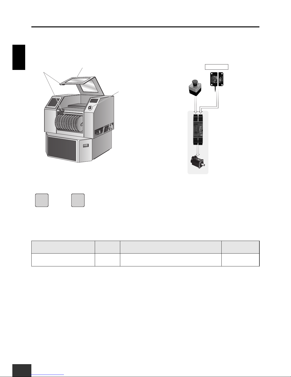
2. Using Non-contact Door Switch
2-1 Pick and Place Machine
If the Emergency Stop Switch is pressed, the entire machine will stop.
If the cover is opened, the entire machine will stop.
Required Units
Unit Qty. Safety input to be applied Page
G9SX-NSA 1
Emergency Stop Switch +
Non-contact Door Switch D40A
43
G9SX-NSA
(1) Emergency Stop
Switch
Motor
(1) Emergency Stop
Switch
(1) The Emergency Stop
Switch is pressed.
Operation Example
Cover
Cover
(2) Non-contact
Door Switch
(2) Non-contact
Door Switch
D40A
Segment A
Stop
Segment A
Stop
Segment A
Stop
Segment A
Stop
Segment A
Stop
Segment A
Stop
Segment A
Stop
Motor
Stop
Segment A
Stop
Segment A
Stop
Segment A
Stop
Segment A
Stop
Segment A
Stop
Segment A
Stop
Segment A
Stop
Motor
Stop
(2) Cover is opened.
Page 21
2. Using Non-contact Door Switch
G9SX
USER'S GUIDE
21
Application ExamplesSection 1
■ Wiring Example
Setup (For details, refer to Section 3.)
G9SX-NSA: Manual reset, Cross fault detection mode: OFF (Category 2 Wiring), Logical AND connections: OFF,
OFF-delay time setting
Wiring Example
■ Timing chart
S14
M1
KM2
KM1
OFF
AND
G9SX-NSA222-T03
Control circuit
KM2
KM1
+24V
GND
S3
S2
+24V
+24V
12
11
S1
Motor controller
(Operation command)
X2X1L1
S54S44
A2
A1
S24S14
T11 T12 T21 T22 T31 T32 T33 T41 T42
Y1 D1 D2 D3 D4
KM2KM1
Feedback Loop
Non-contact
Door Switch
Actuator
Black
Brown
White
blue
PLC etc.
NCNC
Motor controller
NC
NC
S1 : Emergency Stop Switch
S2 : Non-contact Door Switch
S3 : Reset switch
KM1, KM2 : Contactor
M1 : 3-phase motor
Note: This example corresponds to category 2.
Emergency Stop Switch S1
Non-contact
Door Switch S2
OFF-delay time
Emergency Stop
Switch operation
OFF-delay time
KM1, KM2 NC contact
KM1, KM2 NO contact
Operation command
Rotation of motor
Reset switch S3
Page 22
Application ExamplesSection 1
2. Using Non-contact Door Switch
22
G9SX
USER'S GUIDE
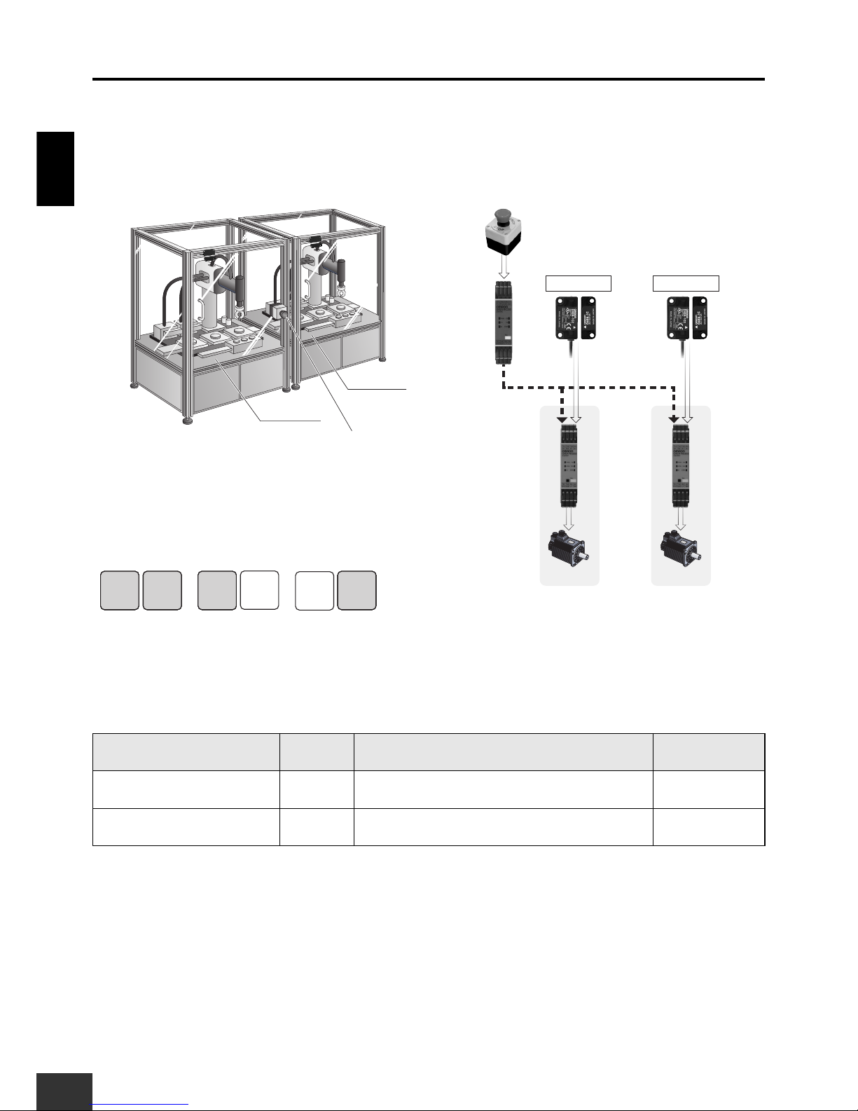
2-2 Small Assembly System
When the Emergency Stop Switch is pressed, both robots will stop.
When robot door A is opened, robot A will stop.
When robot door B is opened, robot B will stop.
Required Units
Unit Qty. Safety input to be applied Page
G9SX-BC 1 Emergency Stop Switch 39
G9SX-NS 2 Non-contact Door Switches D40A (Set of two) 42
Robot A Robot B
Logical AND connections
(1) Emergency Stop
Switch
D40A
G9SX-NS G9SX-NS
(2) Robot door A (3) Robot door B
(2) Robot door A
(3) Robot door B
G9SX-BC
D40A
(2) Robot door A
opened.
(3) Robot door B
opened.
(1) Emergency Stop
Switch
StopStopStopStop
Stop
Robot A
StopStopStopStop
Robot A
StopStopStopStop
Robot B Robot B
StopStopStopStop
Stop
Robot B
Robot A
(1) The Emergency Stop
Switch is pressed.
Operation Example
Page 23
2. Using Non-contact Door Switch
G9SX
USER'S GUIDE
23
Application ExamplesSection 1
■ Wiring Example
Setup (For details, refer to Section 3.)
G9SX-BC: Manual reset, Cross fault detection mode: ON (Category 4 Wiring)
G9SX-NS: Auto reset, Logical AND connections (Category 3 Wiring)
Wiring Example
Note: This example corresponds to category 3.
M3
KM6
KM5
KM6
KM5
+24V
NC
+24V
OFF
AND
G9SX-NS202
(Robot door B)
Control circuit
S4
KM6KM5
S14 S24
A2
A1 D1 D3 D4 Y1
T31 T32 T33
T41 T42
D2
L1 X1 X2
NC
Y1
M2
KM4
KM3
KM4
KM3
+24V+24V
OFF
AND
G9SX-NS202
(Robot door A)
S3
KM4KM3
S14 S24
A2
A1 D1 D3 D4
T31 T32 T33
T41 T42
D2
L1 X1 X2
KM2
KM1
S2
12
11 21
22
+24V
M1
KM2
KM1
S1
+24V
NC
G9SX-BC202
Control circuit
KM2KM1
S14 S24
A2
A1
T11T11 T12 T21 T22 T31 T32 T33
Y1
L1 L2 X1 X2
Feedback Loop
GND
GND GND
Control circuit
PLC etc.
Actuator
Non-contact
Door Switch
Actuator
Non-contact
Door Switch
Feedback Loop Feedback Loop
PLC etc.
PLC etc.
S1 : Emergency Stop Switch
S2 : Reset switch
S3, S4 : Non-contact Door Switch
KM1 to KM6 : Contactor
M1 to M3 : 3-phase motor
Page 24
Application ExamplesSection 1
2. Using Non-contact Door Switch
24
G9SX
USER'S GUIDE
■ Timing chart
(1) Before operation is started.
(2) Robot door A is opened and robot A stops.
(3) Robot door A is closed and robot A restarts.
(4) Robot door B is opened and robot B stops.
(5) Robot door B is closed and robot B restarts.
(6) If the Emergency Stop Switch is pressed, the upper unit, lower unit A, and lower unit B will all stop.
G9SX-NS202 (lower unit : Robot A)
G9SX-NS202 (lower unit : Robot B)
Emergency Stop Switch S1
Reset switch S2
Logical AND output L1
KM1, KM2 NC contact
KM1, KM2 NO contact
G9SX-BC202 (upper unit)
Logical AND input T41
Logical AND input T41
KM3, KM4 NC contact
KM3, KM4 NO contact
KM5, KM6 NC contact
KM5, KM6 NO contact
Non-contact
Door Switch S3
Non-contact
Door Switch S4
Rotation of motor M3
Rotation of motor M2
Rotation of motor M1
(6)
(1) (2) (3)
(4) (5)
Page 25
G9SX
USER'S GUIDE
25
Application ExamplesSection 1
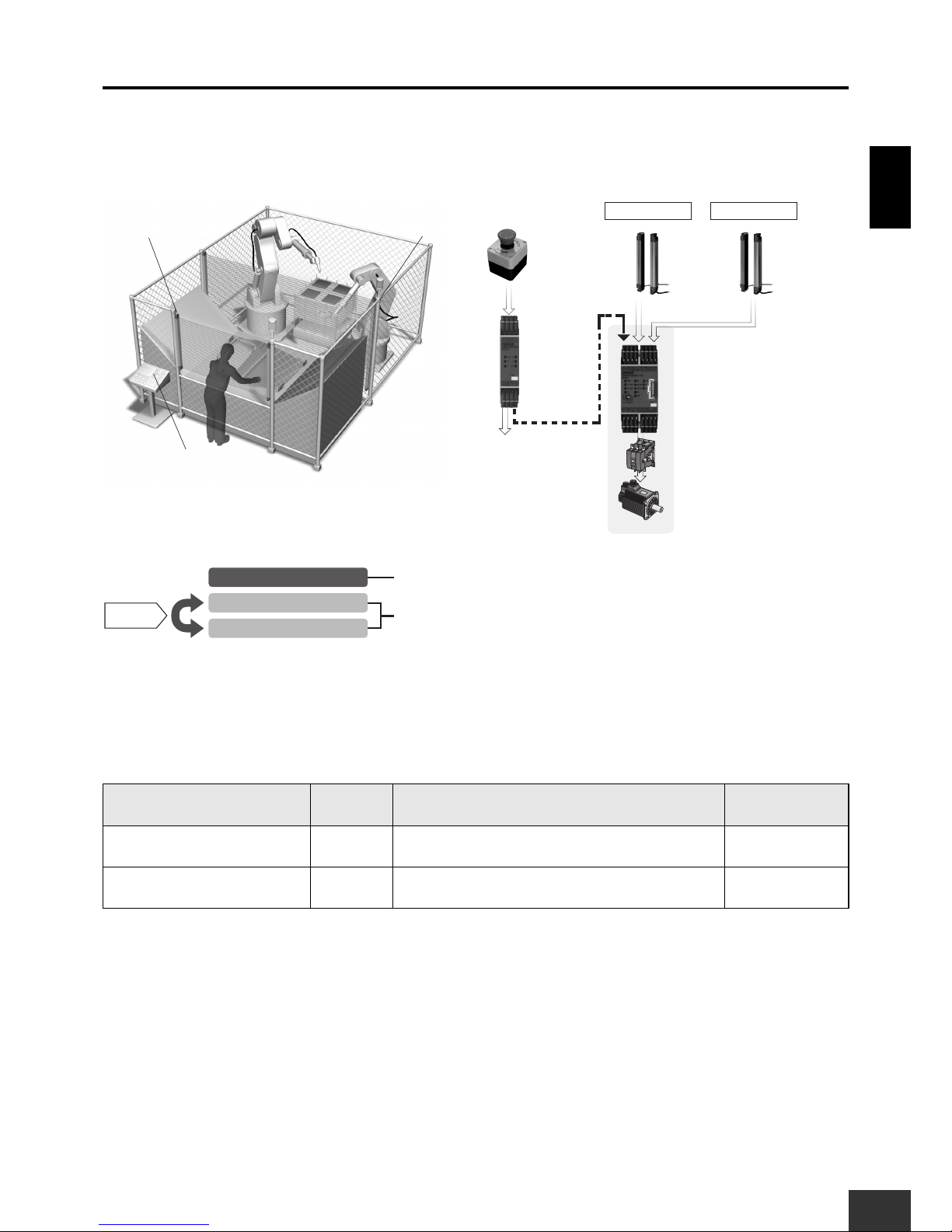
3. Coordinated operation of worker and machine
3-1
Manufacturing Automotive Parts Using Semi-automatic Processing
Two pairs of Light Curtains are automatically enabled and disabled according to the operations
of the operator and robot.
Required Units
Unit Qty. Safety input to be applied Page
G9SX-BC 1 Emergency Stop Switch 39
G9SX-GS 1 Light Curtain + Light Curtain 44
Basic Unit
G9SX-BC
Logical AND
connection
(1) Emergency
Stop Switch
A22E
(1) Emergency
Stop Switch
(2) Safety Light
Curtain A
(3) Safety Light
Curtain B
Safety Light
Curtain
F3SJ
Safety Light
Curtain
F3SJ
(2) Safety Light Curtain A (3) Safety Light Curtain B
Safety Guard
Switching Unit
G9SX-GS
Robot
Contactor
Auto switching
Emergency Stop Switch
Safety Light Curtain A
Safety Light Curtain B
When pressed, processing will stop.
When both are interrupted simultaneously, processing will stop.
Page 26
Application ExamplesSection 1
3. Coordinated operation of worker and machine
26
G9SX
USER'S GUIDE
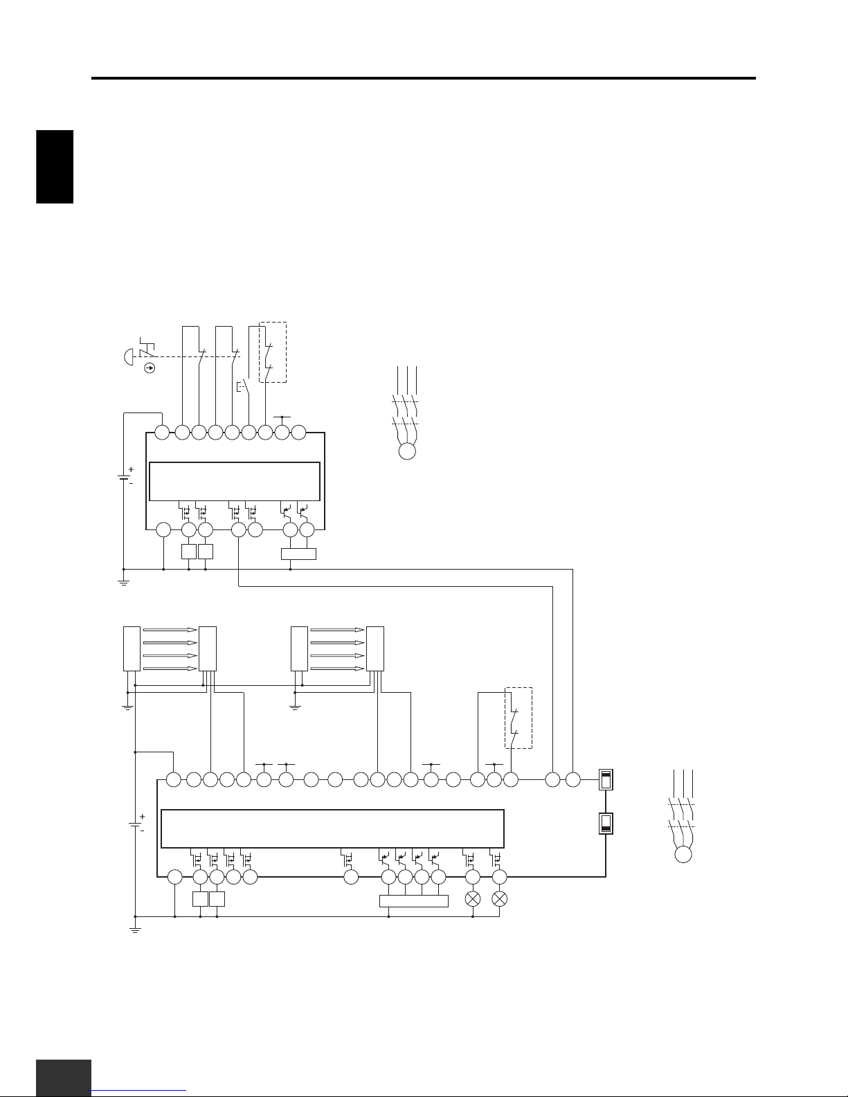
■ Wiring Example
Setup (For details, refer to Section 3.)
G9SX-BC: Manual reset, Cross fault detection mode: ON (Category 4 Wiring)
G9SX-GS: Auto reset, Cross fault detection mode: OFF (Category 4 Wiring (with Safety Light Curtains)),
Logical AND connections,
OFF-delay time setting
Switching mode: Auto
Diagnostic check of Indicator : Enabled (UB only)
Wiring Example
Note: This example corresponds to category 4.
S2
12
11 21
22
+24V
S1
+24V
+24V+24V +24V
+24V
G9SX-BC202
Control circuit
G9SX-GS226-T15
GND GND
+24V
GND
GND
M2
KM4
KM3
Auto
Manual
OFF
AND
T42T41T33T32T31
Y4Y2
T72T71T62
T61
M2M1Y3Y1
T22T21T12T11
A1
KM3
KM4
Control circuit
UB
UAX4X3X2X1L1
KM4KM3
S54S44S24S14
A2
M1
KM1
KM2
KM2
KM1
Y1
T33T32T31T22
A1
T11 T12 T21
X2X1L2L1
S14 S24
KM1 KM2
A2
F3SJ-A F3SJ-A
NC
Emergency
Stop Switch
PLC etc.
Feedback loop
ReceiverEmitter ReceiverEmitter
Safety Sensor A Safety Sensor B
NCNCNC NC NC NC
Control output 2
Control output 1
Control output 1
Control output 2
PLC etc.
Indicator
(Diagnostic
check disabled)
Indicator
(Diagnostic
check enabled)
NC
Feedback Loop
S1 : Emergency Stop Switch
S2 : Reset switch
KM1 to KM4 : Contactor
M1 to M2 : 3-phase motor
Page 27
3. Coordinated operation of worker and machine
G9SX
USER'S GUIDE
27
Application ExamplesSection 1
■ Timing chart
(1) Before operation is started.
(2) Operator inserts workpiece
(3) Robot processes workpiece
(4) Both operator and robot enter the coordinated area: Only the G9SX-GS stops.
(5) The G9SX-GS restarts.
(6) Emergency stop button pressed: All units stop.
Emergency Stop Switch S1
Reset switch S2
Logical AND output L1
KM1, KM2 NC contact
KM1, KM2 NO contact
External indicator output UA
Logical AND input T41
Safety Sensor B control output
(monitoring the operator)
Safety Sensor A control output
(monitoring the robot)
Input B monitor output X4
Input A monitor output X3
External indicator output UB
Controls not related to safety
KM3, KM4 NC contact
KM3, KM4 NO contact
Robot movement enabled
Robot movement disabled
Robot movement enabled in
specific area only
G9SX-BC202
G9SX-GS226-T15
(3)
(1)
(4) (5)
(2)
(6)
Page 28
28
G9SX
USER'S GUIDE
Application ExamplesSection 1
4. Safety Measures for limited operations
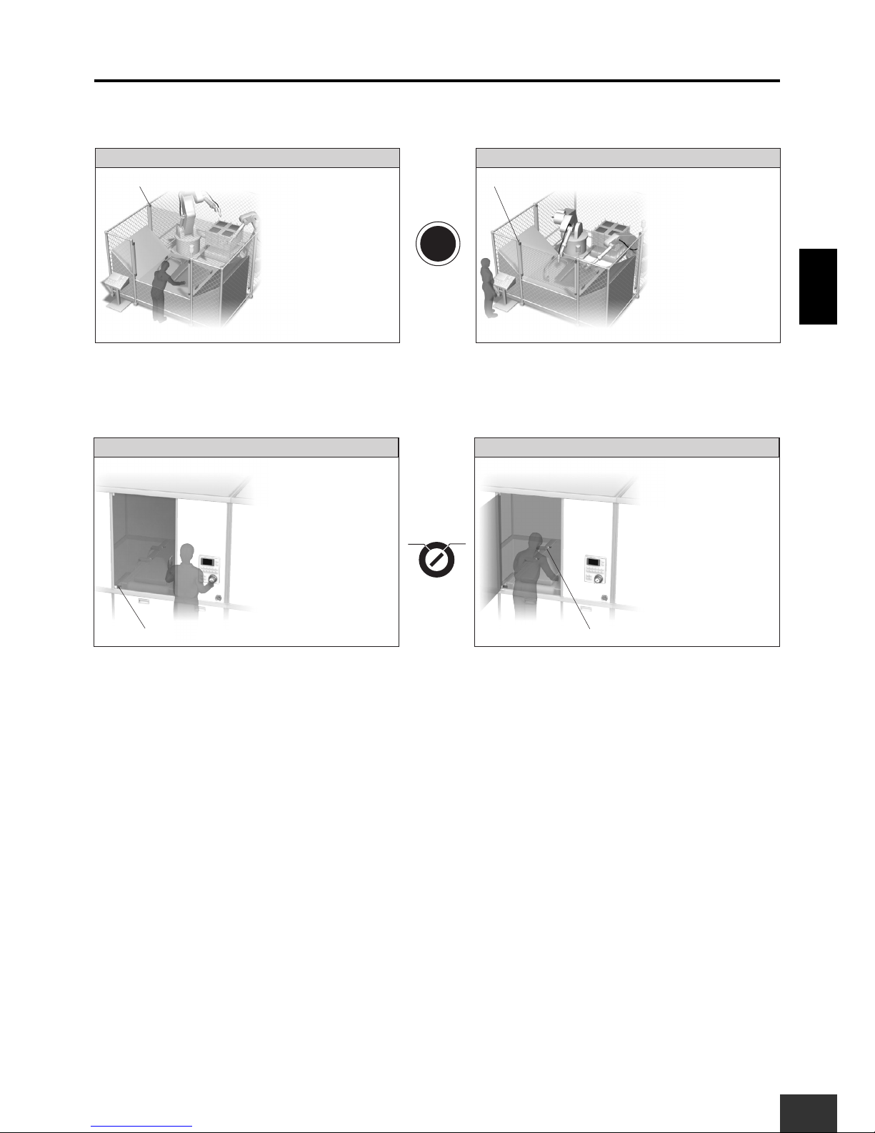
4-1 Manufacturing Flat-panel Displays (Maintenance)
Switching between Normal Operating Mode and Maintenance Mode is performed manually.
In
Normal Operating
Mode, the Safety Door Switch is enabled, and in Maintenance Mode
the Safety Limit Switch is enabled.
Required Units
Unit Qty. Safety input to be applied Page
G9SX-BC 1 Emergency Stop Switch 39
G9SX-GS 1 Door Switch + Limit Switch 44
(1) Emergency
Stop Switch
(3) Conveyor cart
(Safety Limit Switch)
(2) Cover (Safety Door Switch)
(4) Mode selector
(3) Conveyor cart (4) Mode selector(2) Cover
Safety Limit
Switch
D4F
Key-type
Selector Switch
A22K
Safety Door
Switch
D4NS
Safety Guard
Switching Unit
G9SX-GS
Contactor
Basic Unit
G9SX-BC
Logical AND
connection
(1) Emergency
Stop Switch
A22E
Conveyor cart
Emergency Stop Switch
Normal operating mode
Maintenance mode
Cover
Conveyor cart
When pressed, processing will stop.
When the cover is opened, processing will stop.
Emergency Stop Switch
Cover
Conveyor cart
When pressed, processing will stop.
Processing will continue regardless of whether the cover is opened or closed.
Processing will continue regardless of the conveyor cart position.
When the conveyor cart moves away from its safe position, processing will stop.
Manual
switching
Manual
switching
Page 29
4. Safety Measures for limited operations
G9SX
USER'S GUIDE
29
Application ExamplesSection 1
■ Wiring Example
Setup (For details, refer to Section 3.)
G9SX-BC: Manual reset, Cross fault detection mode: ON (Category 4 Wiring)
G9SX-GS: Manual reset, Cross fault detection mode: ON (Category 4 Wiring), Logical AND connections,
OFF-delay time setting
Switching mode: Manual
Diagnostic check of Indicator: Enabled (UA only)
Wiring Example
Note: This example corresponds to category 4.
S14A2S24
L1 L2 X1 X2
T11A1T12 T21 T22 T31 T32 T33
Y1
KM2
KM1
S2
12
11 21
22
+24V
KM1 KM2
M1
KM2
KM1
S1
KM4
KM3
+24V
+24V
+24V
M2
KM4
KM3
KM4KM3
G9SX-BC202
Control circuit
S14A2S24
S44
S54
L1 X3X2X1 X4 UA
T11A1T12 T21
Y1
Y3
T22
T61 T62
M1 M2
T71
Y2
Y4
T72 T31 T32 T33 T41 T42
OFF
AND
Auto
Manual
G9SX-GS226-T15
Control circuit
23
24
11
12
11
12
S3
S4
21
22
S6
+24V
GND
UB
+24V
S5
NC
Feedback loop
Emergency
Stop Switch
PLC etc.
NCNC
Mode selector
Cover
NC
Feedback loop
PLC etc.
Indicator
(Diagnostic
check enabled)
Indicator
(Diagnostic
check disabled)
Conveyor cart
S1 : Emergency Stop Switch
S2, S7 : Reset switch
S3, S4 : Safety Limit Switch
S5 : Safety Door Switch
S6 : Selector switch
KM1 to KM4 : Contactor
M1 to M2 : 3-phase motor
Page 30
Application ExamplesSection 1
4. Safety Measures for limited operations
30
G9SX
USER'S GUIDE
■ Timing chart
(1) Start the G9SX-GS in normal operating mode.
(2) Switch to maintenance mode.
(3) The operator opens the door and performs maintenance.
(4) When Safety Limit Switch S3 and Limit Switch S4 are turned OFF in maintenance mode, the G9SX-GS stops.
(5) After the door is closed and the operating mode is switched to normal operating mode, restart the G9SX-GS.
(6) When the door is opened during normal operating mode, the G9SX-GS stops.
(7) Close the door and restart the G9SX-GS.
(8) When the operating mode is switched to maintenance mode while Safety Limit Switch S3 and Limit Switch S4 are turned OFF, the G9SX-GS
stops.
(9) Switch to normal operating mode, and when the door is closed, restart the G9SX-GS.
(10) Emergency stop button pressed: All units stop.
Emergency Stop Switch S1
Reset switch S2
Logical AND output L1
KM1, KM2 NC contact
KM1, KM2 NO contact
Input B monitor output X4
Input A monitor output X3
External indicator output UB
External indicator output UA
Logical AND input T41
Mode selector input M2
Safety Limit Switch S3
Mode selector input M1
Reset switch S6
Safety Door Switch
KM3, KM4 NC contact
KM3, KM4 NO contact
Limit Switch S4
Conveyor section movement enabled
(with machine in normal operating mode)
Conveyor section movement enabled in
specific area only
(with machine in maintenance mode)
Conveyor section movement disabled
G9SX-BC202
G9SX-GS226-T15
Controls not related to safety
(1)
(2)
(3)
(4)
(5)
(6)
(7)
(8)
(9)
(10)
Page 31

4. Safety Measures for limited operations
G9SX
USER'S GUIDE
31
Application ExamplesSection 1
4-2 Machining Center (Enabling Switch)
Switching between Normal Operating Mode and Maintenance Mode is performed manually.
In
Normal Operating
Mode, the Safety Door Switch is enabled, and in Maintenance Mode,
the Safety Limit Switch is enabled.
Required Units
Unit Qty. Safety input to be applied Page
G9SX-BC 1 Emergency Stop Switch 39
G9SX-GS 1 Door Switch + Enabling Switch 44
Enabling
Switch
Door
Enabling Device
Enabling Device
Guard Lock
Safety Door
Switches
(3) Enabling Switch
Emergency Stop Switch
Normal operating mode
Maintenance mode
When pressed, processing will stop.
When the door is opened, processing will stop.
The enabling switch is disabled.
When pressed, processing will stop.
Door Switch is disabled.
Processing will be possible only when the operator is gripping the enabling
switch.
Emergency Stop Switch
Manual
switching
Manual
switching
(4) Mode selector(3) Motor(2) Door
Key-type
Selector Switch
A22K
Safety Guard
Switching Unit
G9SX-GS
Contactor
Basic Unit
G9SX-BC
Logical AND
connection
(1) Emergency
Stop Switch
A22E
Conveyor cart
(1) Emergency
Stop Switch
(2) Safety Door Switch
Door
Page 32

Application ExamplesSection 1
4. Safety Measures for limited operations
32
G9SX
USER'S GUIDE
■ Wiring Example
Setup (For details, refer to Section 3.)
G9SX-BC: Manual reset, Cross fault detection mode: ON (Category 4 Wiring)
G9SX-GS: Manual reset, Cross fault detection mode: ON (Category 4 Wiring), Logical AND connections,
OFF-delay time setting
Switching mode: Manual
Diagnostic check of Indicator: Enabled
Wiring Example
S14A2S24
L1 L2 X1 X2
T11A1T12 T21 T22 T31 T32 T33
Y1
KM2
KM1
S2
12
11 21
22
+24V
KM1 KM2
M1
KM2
KM1
PLC etc.
S1
KM4
KM3
+24V
+24V
M2
KM4
KM3
KM4KM3
PLC etc.
NC NC
NC
NCNC
Feedback Loop
Feedback Loop
G9SX-BC202
Control circuit
S14A2S24
S44
S54
L1 X3X2X1 X4
T11A1T12 T21
Y1
Y3
T22
T61 T62
M1 M2
T71
Y2
Y4
T72 T31 T32 T33 T41 T42
OFF
AND
Auto
Manual
G9SX-GS226-T15
Control circuit
S3
S7
+24V
GND
GND
Enabling
Switch
S4
OPEN
S5
KM3
KM4
31
32
11
12
Stop sigmal
Door
S6
UA UB
+24V
Indicator
(Diagnostic
check enabled)
Indicator
(Diagnostic
check enabled)
Mode selector
Lock release signal
2 4
1 3
S1 : Emergency Stop Switch
S2, S7 : Reset switch
S3 : Enabling Switch
S4 : Guard Lock Door Switch
S5 : Lock release switch
S6 : Safety Limit Switch
KM1 to KM4 : Contactor
M1 to M2 : 3-phase motor
Note: This example corresponds to category 4.
Page 33

4. Safety Measures for limited operations
G9SX
USER'S GUIDE
33
Application ExamplesSection 1
■ Timing chart
(1) In Normal operating mode, the lower unit starts.
(2) Maintenance mode is selected.
(3) The operator opens the door and performs maintenance operation.
(4) The Enabling Switch is gripped to the middle position.
(5) In maintenance mode, the lower unit starts.
(6) When the Enabling Switch is released or gripped, the lower unit stops.
(7) After closing the door and then switching to Normal operating mode, the lower unit will restart.
(8) If the door is opened while in Normal operating mode, the lower unit will stop.
(9) The door is closed, and the lower unit restarts.
(10) If the Emergency Stop Switch is pressed, the upper unit and lower unit will stop.
Guard Lock Door Switch S4
Enabling Switch S3
Emergency Stop Switch S1
Reset switch S2
Logical AND output L1
KM1, KM2 NC contact
KM1, KM2 NO contact
G9SX-BC202 (upper unit)
G9SX-GS226-T15 (lower unit)
Logical AND input T41
Reset switch S7
OFF-delay time OFF-delay time OFF-delay time OFF-delay time
(4) (6)
(7) (9)
(10)
(5)
(2)
(3) (8)
(1)
KM3, KM4 NC contact
KM5, KM6 NC contact
KM3, KM4 NO contact
KM5, KM6 NO contact
Mode selector input M2
Mode selector input M1
Page 34

Application ExamplesSection 1
4. Safety Measures for limited operations
34
G9SX
USER'S GUIDE
4-3 LCD Manufacturing (Guard Lock Control)
When the Safety Limit Switch has confirmed that the hazard source is in a safe position,
the Guard Lock Safety Door Switch will be unlocked.
Required Units
Unit Qty. Safety input to be applied Page
G9SX-BC 1 Emergency Stop Switch 39
G9SX-GS 1 Guard Lock Door Switch + Limit Switch 44
Guard Lock Door Switch
Guard Lock
Safety Door
Switches
(2) Guard Lock Door Switch
(1) Emergency
Stop Switch
(3) Safety Limit Switch
Safety Guard
Switching Unit
G9SX-GS
Motor
Contactor
Basic Unit
G9SX-BC
Logical AND
connection
(1) Emergency
Stop Switch
A22E
(3) Conveyor cart(2) Door
Emergency Stop Switch
Auto
switching
When pressed, processing will stop.
When turned OFF at the same time, the machine will stop.
Safety Limit
Switch
D4F
Limit Switch
Page 35

4. Safety Measures for limited operations
G9SX
USER'S GUIDE
35
Application ExamplesSection 1
■ Wiring Example
Setup (For details, refer to Section 3.)
G9SX-BC: Manual reset, Cross fault detection mode: ON (Category 4 Wiring)
G9SX-GS: Manual reset, Cross fault detection mode: ON (Category 4 Wiring), Logical AND connections,
No OFF-delay time setting
Switching mode: Auto
Diagnostic check of Indicator: Enabled (UA only)
Wiring Example
S14A2S24
L1 L2 X1 X2
T11A1T12 T21 T22 T31 T32 T33
Y1
KM2
KM1
S2
12
11 21
22
+24V
KM1 KM2
M1
KM2
KM1
PLC etc.
S1
KM4
KM3
+24V
+24V
M2
KM4
KM3
KM4KM3
NC
NC
NCNC
Feedback Loop
Feedback Loop
G9SX-BC202
Control circuit
S14A2S24
S44
S54
L1 X3X2X1 X4 UA
T11A1T12 T21
Y1
Y3
T22
T61 T62
M1 M2
T71
Y2
Y4
T72 T31 T32 T33 T41 T42
OFF
AND
Auto
Manual
G9SX-GS226-T15
Control circuit
S5
S6
Limit Switch
Limit
Switch
Limit
Switch
Guard Lock
Door Switch
(Mechanical lock)
S4
Conveyor cart
S7
+24V
GND
GND
UB
+24V
GND
OPEN
42
41
12
11
22
E1 E2
21
Door
Indicator
(Diagnostic
check enabled)
Lock release
switch
S1 : Emergency Stop Switch
S2, S7 : Reset switch
S3 : Lock release switch
S4 : Guard Lock Door Switch
S5, S6 : Limit Switch
KM1 to KM4 : Contactor
M1 to M2 : 3-phase motor
Note: This example corresponds to category 4.
Page 36

Application ExamplesSection 1
4. Safety Measures for limited operations
36
G9SX
USER'S GUIDE
■ Timing chart
(1) When the door is closed, operation is initiated with the reset switch.
(2) The Limit Switch detects the conveyor cart and the lock release signal turns ON.
(3) The door can be opened while the lock release switch pressed.
(4) The door is closed again.
(5) The conveyor cart moves.
(6) The Limit Switch detects the conveyor cart, and the lock release signal turns ON.
(7) The door can be opened while the lock release switch is pressed.
(8) The conveyor cart moves while the door is open, and the lower unit stops.
(9) The door is closed again. The lower unit remains stopped.
(10) The reset switch is used to restart operation.
(11) If the Emergency Stop Switch is pressed, the upper unit and lower unit will stop.
Emergency Stop Switch S1
Reset switch S2
Logical AND output L1
KM1, KM2 NC contact
KM1, KM2 NO contact
G9SX-BC202 (upper unit)
G9SX-GS226-T15 (lower unit)
Logical AND input T41
Reset switch S7
KM3, KM4 NC contact
KM3, KM4 NO contact
(6)(5)(1)
(3) (4) (9)
(10)
(11)
(2) (7) (8)
Safety Limit Switch S5
Safety Limit Switch S6
Lock release signal
Lock release switch S1
Door can be opened.Door can be opened.
(External indicator output UA)
Guard Lock Door Switch S4
Page 37

G9SX
USER'S GUIDE
37
Functions of G9SXSection 2
Section
2
Functions of G9SX
1. Function list of G9SX-series 38
2. Functions of each Unit 39
2-1 Basic Unit
39
2-2 Advanced Unit
40
2-3 Non-Contact Door Switch Controller
42
2-4 Safety Guard Switching Unit
44
2-5 Expansion Unit
48
Page 38

38
G9SX
USER'S GUIDE
Functions of G9SXSection 2
1. Function list of G9SX-series
Function Model G9SX-BC G9SX-AD G9SX-ADA G9SX-NS G9SX-NSA G9SX-GS
Logical
AND
connections
Inputs --- ●
●
(2 inputs)
●●●
Outputs ●●●●●●
Safety
inputs
Emergency stop ●●●--- ● ---
Door switch ●●●--- ●●
Non-contact
door switch
(D40A)
--- --- --- ●●---
Light curtain ●●●--- --- ●
Number of safety inputs 1 1 1 1 2 2
Safety
outputs
Instantaneous
outputs
232222
OFF-delayed
outputs
--- 2 2 --- 2 2
OFF-delay time ---
0 to 15 s,
0 to 150 s
0 to 15 s,
0 to 150 s
--- 0 to 3 s 0 to 15 s
Expansion Unit
connection
--- ●●--- ●●
Guard switching --- --- --- --- --- ●
Page 39

G9SX
USER'S GUIDE
39
Functions of G9SXSection 2
2. Functions of each Unit
2-1 Basic Unit
It is possible to connect to other Units by using the logical AND connection output.
■ G9SX-BC@
Safety Inputs
Safety Outputs (Semiconductor Outputs)
Logical AND Connections
Required Settings and Wiring
LED Indicators
Safety inputs 1 input (2-channel input)
Safety input devices
Emergency stop switch, door switch,
light curtain
Instantaneous outputs
2 outputs
OFF-delayed outputs
None
Number of inputs None
Number of outputs 2 outputs
Item G9SX-BC Page
Logical AND connection
input enable/disable
--- ---
Cross fault detection mode ❍ 63
Reset mode ❍ 62
OFF-delay time --- ---
Switching mode --- ---
External indicator fault
diagnosis mode
--- ---
Safety Input
Safety
Instantaneous
Output
Logical AND
Connection
Output
No.
T1 T2
FB
ERREI
PWR
L2L1S24S14
A2X2T22T21
A1X1T12T11
Y1T32 T33T31
G9SX-BC202
24VDC
Marking Color Name
PWR Green Power supply indicator
T1 Orange Safety input #1 indicator
T2 Orange Safety input #2 indicator
FB Orange Feedback/reset input indicator
EI Orange Safety output indicator
ERR Red Error indicator
No.
T1 T2
FB
ERREI
PWR
L2L1S24S14
A2X2T22T21
A1X1T12T11
Y1T32 T33T31
G9SX-BC202
24VDC
Page 40

Functions of G9SXSection 2
2. Functions of each Unit
40
G9SX
USER'S GUIDE
2-2 Advanced Unit
This Unit has safety OFF-delayed outputs and can be connected to other Units using the logical AND connection
input and output.
■ G9SX-AD@
Safety Inputs
Safety Outputs (Semiconductor Outputs)
Note: The OFF-delayed outputs can be used as instantaneous outputs by
setting the OFF-delay time to 0 s.
Logical AND Connections
OFF-delay Time Setting
Required Settings and Wiring
LED Indicators
Safety inputs 1 input (2-channel input)
Safety input devices
Emergency stop switch, door switch,
light curtain
Instantaneous outputs
3 outputs
OFF-delayed outputs
2 outputs
Number of inputs 1 input
Number of outputs 1 output
G9SX-AD322-T15-@ 0 to 15 s
G9SX-AD322-T150-@ 0 to 150 s
Item G9SX-AD Page
Logical AND connection
input enable/disable
❍ 57
Cross fault detection mode ❍ 63
Reset mode ❍ 62
OFF-delay time ❍ 65
Switching mode --- ---
External indicator fault
diagnosis mode
--- ---
Safety Input
Safety
Instantaneous
Output
Safety
OFF-delayed
Output
Logical AND
Connection
Output
Logical AND
Connection
Input
No.
OFF-DELAY
0.5
0.4
0.3
0.2
15
10
7
5
4
3
2
1.5
1
0.6
0.7
0
S54S44S34S24S14 L1
A2T42T41T22T21
A1X2X1Y1T12T11
T33T31
T1
ERR
EI
AND
FB
ED
T2
PWR
T32
G9SX-AD322-T15
24VDC
Marking Color Name
PWR Green Power supply indicator
T1 Orange Safety input #1 indicator
T2 Orange Safety input #2 indicator
FB Orange Feedback/reset input indicator
AND Orange Logical AND input indicator
EI Orange Safety output indicator
ED Orange
OFF-delayed safety output
indicator
ERR Red Error indicator
No.
OFF-DELAY
0.5
0.4
0.3
0.2
15
10
7
5
4
3
2
1.5
1
0.6
0.7
0
S54S44S34S24S14 L1
A2T42T41T22T21
A1X2X1Y1T12T11
T33T31
T1
ERR
EI
AND
FB
ED
T2
PWR
T32
G9SX-AD322-T15
24VDC
Page 41

2. Functions of each Unit
G9SX
USER'S GUIDE
41
Functions of G9SXSection 2
■ G9SX-ADA@
Safety Inputs
Safety Outputs (Semiconductor Outputs)
Note: The OFF-delayed outputs can be used as instantaneous outputs by
setting the OFF-delay time to 0 s.
Logical AND Connections
OFF-delay Time Setting
Required Settings and Wiring
LED Indicators
Safety inputs 1 input (2-channel input)
Safety input devices
Emergency stop switch, door switch,
light curtain
Instantaneous outputs
2 outputs
OFF-delayed outputs
2 outputs
Number of inputs 2 inputs
Number of outputs 2 outputs
G9SX-ADA222-T15-@ 0 to 15 s
G9SX-ADA222-T150-@ 0 to 150 s
Item G9SX-ADA Page
Logical AND connection
input enable/disable
❍ 57
Cross fault detection mode ❍ 63
Reset mode ❍ 62
OFF-delay time ❍ 65
Switching mode --- ---
External indicator fault
diagnosis mode
--- ---
Safety Input
Safety
Instantaneous
Output
Safety
OFF-delayed
Output
Logical AND
Connection
Output
Logical AND
Connection
Input
No.
OFF-DELAY
0.5
0.4
0.3
0.2
15
10
7
5
4
3
2
1.5
1
0.6
0.7
0
L1S54S44S24S14 L2
A2T42T41T22T21
A1X2X1Y1T12T11
T33T31
T1
ERR
EI
AND1
FB
ED
T2
PWR
T32 T52T51
G9SX-ADA222-T150
24VDC
AND2
Marking Color Name
PWR Green Power supply indicator
T1 Orange Safety input #1 indicator
T2 Orange Safety input #2 indicator
FB Orange Feedback/reset input indicator
AND1 Orange Logical AND input indicator
AND2 Orange Logical AND input indicator
EI Orange Safety output indicator
ED Orange
OFF-delayed safety output
indicator
ERR Red Error indicator
No.
OFF-DELAY
0.5
0.4
0.3
0.2
15
10
7
5
4
3
2
1.5
1
0.6
0.7
0
L1S54S44S24S14 L2
A2T42T41T22T21
A1X2X1Y1T12T11
T33T31
T1
ERR
EI
AND1
FB
ED
T2
PWR
T32 T52T51
G9SX-ADA222-T150
24VDC
AND2
Page 42

Functions of G9SXSection 2
2. Functions of each Unit
42
G9SX
USER'S GUIDE
2-3 Non-Contact Door Switch Controller
This is a Special Controller for D40A Non-contact Door Switch. It can be connected to other Units using the logical
AND connection input and output.
■ G9SX-NS@
Safety Inputs
Safety Outputs (Semiconductor Outputs)
Logical AND Connections
Required Settings and Wiring
LED Indicators
Safety inputs 1 input (2-channel input)
Safety input devices Non-contact door switch (D40A)
Instantaneous outputs
2 outputs
OFF-delayed outputs
None
Number of inputs 1 input
Number of outputs 1 output
Item G9SX-NS Page
Logical AND connection
input enable/disable
❍ 57
Cross fault detection mode --- ---
Reset mode ❍ 62
OFF-delay time --- ---
Switching mode --- ---
External indicator fault
diagnosis mode
--- ---
D40A Input
Safety
Instantaneous
Output
Logical AND
Connection
Output
Logical AND
Connection
Input
No.
NS
FB
ERR
AND
EI
PWR
D4L1S24S14
A2X2T42T41
A1X1D2D1
D3T32 T33T31
G9SX-NS202
24VDC
Marking Color Name
PWR Green Power supply indicator
NS Orange
Non-contact Door Switch input
indicator
FB Orange Feedback/reset input indicator
AND Orange Logical AND input indicator
EI Orange
Instantaneous safety output
indicator
ERR Red Error indicator
No.
NS
FB
ERR
AND
EI
PWR
D4L1S24S14
A2X2T42T41
A1X1D2D1
D3T32 T33T31
G9SX-NS202
24VDC
Page 43

2. Functions of each Unit
G9SX
USER'S GUIDE
43
Functions of G9SXSection 2
■ G9SX-NSA@
Safety Inputs
Safety Outputs (Semiconductor Outputs)
Note: The OFF-delayed outputs can be used as instantaneous outputs by
setting the OFF-delay time to 0 s.
Logical AND Connections
OFF-delay Time Setting
Required Settings and Wiring
LED Indicators
Safety inputs 2 inputs (each with 2 channels)
Safety input devices
Non-contact door switch (D40A),
emergency stop switch, door switch
Instantaneous outputs
2 outputs
OFF-delayed outputs
2 outputs
Number of inputs 1 input
Number of outputs 1 output
G9SX-NSA222-T03-@ 0 to 3 s
Item G9SX-NSA Page
Logical AND connection
input enable/disable
❍ 57
Cross fault detection mode ❍ 63
Reset mode ❍ 62
OFF-delay time ❍ 65
Switching mode --- ---
External indicator fault
diagnosis mode
--- ---
D40A Input
Safety Input
Safety
Instantaneous
Output
Safety
OFF-delayed
Output
Logical AND
Connection
Output
Logical AND
Connection
Input
No.
OFF-DELAY
L1S54S44S24S14 D4
A2T42T41T22T21
A1X2X1Y1T12T11
T33T31
T1
ERR
EI
AND
FB
ED
T2
PWR
T32 D2 D3D1
G9SX-NSA222-T30
24VDC
NS
0.5
0.4
0.3
0.2
3.0
2.5
2.0
1.8
1.4
1.2
1.0
0.9
0.8
0.6
0.7
0
Marking Color Name
PWR Green Power supply indicator
T1 Orange Safety input #1 indicator
T2 Orange Safety input #2 indicator
NS Orange
Non-contact Door Switch input
indicator
FB Orange Feedback/reset input indicator
AND Orange Logical AND input indicator
EI Orange
Instantaneous safety output
indicator
ED Orange
OFF-delayed safety output
indicator
ERR Red Error indicator
No.
OFF-DELAY
L1S54S44S24S14 D4
A2T42T41T22T21
A1X2X1Y1T12T11
T33T31
T1
ERR
EI
AND
FB
ED
T2
PWR
T32 D2 D3D1
G9SX-NSA222-T30
24VDC
NS
0.5
0.4
0.3
0.2
3.0
2.5
2.0
1.8
1.4
1.2
1.0
0.9
0.8
0.6
0.7
0
Page 44

Functions of G9SXSection 2
2. Functions of each Unit
44
G9SX
USER'S GUIDE
2-4 Safety Guard Switching Unit
This Unit can alternately enable two safety inputs. It can be used to construct safety systems for semi-automatic
processing and maintenance work.
■ G9SX-GS@
Safety Inputs
Safety Outputs (Semiconductor Outputs)
Note: The OFF-delayed outputs can be used as instantaneous outputs by
setting the OFF-delay time to 0 s.
Logical AND Connections
OFF-delay Time Setting
Required Settings and Wiring
Note: Carefully read the Precautions on pages 96 to 99 before configuring
a system using the G9SX-GS.
LED Indicators
Safety inputs 2 inputs (each with 2 channels)
Safety input devices Door switch, light curtain
Instantaneous outputs
2 outputs
OFF-delayed outputs
2 outputs
Number of inputs 1 input
Number of outputs 1 output
G9SX-GS226-T15-@ 0 to 15 s
Item G9SX-GS Page
Logical AND connection
input enable/disable
❍ 57
Cross fault detection mode ❍ 63
Reset mode ❍ 62
OFF-delay time ❍ 65
Switching mode ❍ 67
External indicator fault
diagnosis mode
❍ 68
Safety InputSafety Input
Safety
Instantaneous
Output
Safety
OFF-delayed
Output
Logical AND
Connection
Output
Logical AND
Connection
Input
T31 T32 T33
T11
Y1 M1 M2
T12 T61 T62 Y2 Y3
T21 T22
X1 X2 X3 X4 S14 S24
T72T71 T41 T42
24VDC
T1
ERR
G9SX-GS226-T15
EI
T6
FB
ED
UA
PWR
OFF-DELAY
UB
0.2
0
0.3
0.4
0.5
0.6
0.7
1
1.5
2
3
4
5
7
10
15
T2
T7
AND
UA UB
Y4 A1
S44 S54
L1 A2
No.
Marking Color Name
PWR Green Power supply indicator
T1 Orange Safety input A, channel 1 indicator
T2 Orange Safety input A, channel 2 indicator
T6 Orange Safety input B, channel 1 indicator
T7 Orange Safety input B, channel 2 indicator
FB Orange Feedback/reset input indicator
AND Orange Logical AND input indicator
EI Orange Safety output indicator
ED Orange
OFF-delayed safety output indicator
UA Orange
Safety input A disabled state indicator
UB Orange
Safety input B disabled state indicator
ERR Red Error indicator
T31 T32 T33
T11
Y1 M1 M2
T12 T61 T62 Y2 Y3
T21 T22
X1 X2 X3 X4 S14 S24
T72T71 T41 T42
24VDC
T1
ERR
G9SX-GS226-T15
EI
T6
FB
ED
UA
PWR
OFF-DELAY
UB
0.2
0
0.3
0.4
0.5
0.6
0.7
1
1.5
2
3
4
5
7
10
15
T2
T7
AND
UA UB
Y4 A1
S44 S54
L1 A2
No.
Page 45
2. Functions of each Unit
G9SX
USER'S GUIDE
45
Functions of G9SXSection 2
Functions
Auto Switching Function
Manual Switching Function
When the operator inserts the workpiece... While the robot processes the workpiece...
Safety Light Curtain A
Safety Light Curtain B
Safety Light Curtain A
monitors the robot.
The robot can continue
to operate as long as it
does not interrupt Safety
Light Curtain A.
Safety Light Curtain B
monitors the operator.
The robot can continue
to operate as long as the
operator does not
interrupt Safety Light
Curtain B.
Note: If the operator is able to completely enter the zone inside Safety Light Curtain B, a presence detection device, such as a Safety Mat, is
necessary as an additional safety measure.
Auto
switching
• •
• •
During normal operation... During maintenance...
Door Switch Limit Switch
The Door Switch monitors
the opening and closing of
the door during normal
operation.
The machine is able to
operate while the door is
closed.
The Limit Switch monitors
the conveyor cart position
during maintenance.
The machine is able to
operate while the
conveyor cart is in a
specified area.
Manual
switching
Normal
operation
Maintenance
•
•
•
•
Page 46

Functions of G9SXSection 2
2. Functions of each Unit
46
G9SX
USER'S GUIDE
Auto Switching Function
1
2
3
4
ON
ON
ON
ON
ON
ON
OFF
OFF
ON
OFF
OFF
OFF
ON
ON
ON
ON
OFF
OFF
OFF
OFF
OFF
(3) Safety Light
Curtain B
(1) Emergency
Stop Switch
(2) Safety
Light Curtain A
(1) Emergency
Stop Switch
A22E
(2) Safety Light Curtain A
(3) Safety Light Curtain B
Safety Light
Curtain
F3SJ
Safety Light
Curtain
F3SJ
Safety Guard
Switching Unit
G9SX-GS
Auxiliary Output
The auxiliary output
can be used to
notify operators of
the input, output, or
error status.
Programmable
Controllers
CS/CJ Series
External Indicator
Output
The external indicator
output can be used to
notify operators of Safety
Light Curtains that may
safely be interrupted.
External
indicator B
External
indicator A
Contactor
Note: External indicator output may be used as necessary.
Basic Unit
G9SX-BC
Logical AND
connection
Safety Output
Robot
Monitoring
Working condition
G9SX-GS
Safety input
External
indicator
Safety input A
Safety input B
OK to work
Safety output
Safety output Monitor output
External indicator
Input A
monitor
Input B
monitor
Input A
monitor
Input B
monitor
Input A
monitor
Input B
monitor
Input A
monitor
Input B
monitor
Safety input A
Safety input B
Safety output
Safety input A
Safety input B
Safety output
Safety input A
Safety input B
Safety output
Normal operation
Hazardous condition
OK to work
Not OK
to work
Not OK
to work
Indicator A
Indicator B
Indicator A
Indicator B
Indicator A
Indicator B
Indicator A
Indicator B
Welding robot
Emergency
Stop Switch
Conveying robot
Safety Light
Curtain A
Safety Light Curtain B
Welding robot
Emergency
Stop Switch
Conveying robot
Safety Light
Curtain A
Safety Light Curtain B
Welding robot
Emergency
Stop Switch
Conveying robot
Safety Light
Curtain A
Safety Light Curtain B
Monitoring
Welding robot
Emergency
Stop Switch
Conveying robot
Safety Light
Curtain A
Safety Light Curtain B
Page 47

2. Functions of each Unit
G9SX
USER'S GUIDE
47
Functions of G9SXSection 2
Manual Switching Function
4
2
3
1
ON
ON
OFF
ON
ON
OFF
ON
OFF
OFF
OFF
ON
ON
ON
ON
OFF
OFF
OFF
Disa-
bled
Disa-
bled
Disa-
bled
Disa-
bled
Disa-
bled
Basic Unit
G9SX-BC
Logical AND
connection
(1) Emergency
Stop Switch
A22E
(1) Emergency
Stop Switch
(3) Safety
Limit Switch
(2) Safety Door Switch
(4) Mode selector
Safety output
Safety
Limit Switch
D4F
Key-type
Selector Switch
A22K
Safety Door
Switch
D4NS
Safety Guard
Switching Unit
G9SX-GS
(2) Cover (3) Conveyor cart
Conveyor cart
(4) Mode selector
Auxiliary Output
The auxiliary output
can be used to
notify operators of
the input, output, or
error status.
External Indicator
Output
The external indicator
output can be used to
notify operators that the
cover may be opened.
Contactor
Note: External indicator output may be used as necessary.
External
indicator A
External
indicator B
Programmable
Controllers
CS/CJ Series
Normal
operating mode
Working condition
G9SX-GS
Safety input
External
indicator
Safety input A
Safety input B
Safety output
Safety output Monitor outputMode selector
External indicator
Input A
monitor
Input B
monitor
Input A
monitor
Input B
monitor
Input A
monitor
Input B
monitor
Input A
monitor
Input B
monitor
Safety input A
Safety input B
Safety output
Safety input A
Safety input B
Safety output
Safety input A
Safety input B
Safety output
Normal operationMaintenance
Hazardous condition
Maintenance
mode
Maintenance
mode
Maintenance
mode
Not OK
to open
OK
to open
OK
to open
OK
to open
Indicator A
Indicator B
Indicator B
Indicator A
Indicator B
Indicator A
Indicator B
Indicator A
Emergency
Stop Switch
Mode
selector
Limit
Switch
Door Switch
Disa-
bled
Moni-
toring
Emergency
Stop
Switch
Mode
selector
Limit
Switch
Door Switch
Emergency
Stop Switch
Mode
selector
Limit
Switch
Door Switch
Emergency
Stop Switch
Mode
selector
Limit
Switch
Door Switch
Moni-
toring
Disa-
bled
Moni-
toring
Disa-
bled
Moni-
toring
Disa-
bled
Page 48

Functions of G9SXSection 2
2. Functions of each Unit
48
G9SX
USER'S GUIDE
2-5 Expansion Unit
By connecting an Expansion Unit to the G9SX-AD/ADA, G9SX-NSA, or G9SX-GS, safety relay contact outputs can
be added that are synchronized with the safety outputs of the Unit to which the Expansion Unit is connected.
■ G9SX-EX-@
Safety Outputs (Safety Relay Outputs)
Logical AND Connections
Required Settings and Wiring
Note: Refer to 2-10 Connecting Expansion Units on page 69.
LED Indicators
Instantaneous outputs 4 outputs
OFF-delayed outputs None
Number of inputs None
Number of outputs None
Item G9SX-EX Page
Logical AND connection
input enable/disable
--- ---
Cross fault detection mode --- ---
Reset mode --- ---
OFF-delay time --- ---
Switching mode --- ---
External indicator fault
diagnosis mode
--- ---
G9SX-AD
G9SX-ADA
G9SX-NSA
G9SX-GS
G9SX-EX
G9SX-EX
Insert the
connector
Insert the
connector
Safety
Instantaneous
Output
Marking Color Name
PWR Green Power supply indicator
EI Orange Safety output indicator
ERR Red Error indicator
PWR
EI
ERR
Page 49

2. Functions of each Unit
G9SX
USER'S GUIDE
49
Functions of G9SXSection 2
■ G9SX-EX-T@
Safety Outputs (Safety Relay Outputs)
Logical AND Connections
Required Settings and Wiring
Note: 1. The OFF-delay time on G9SX-EX-T is set from the OFF-delay
preset time on the connected unit (G9SX-AD/-ADA/-NSA/-GS).
2. Refer to 2-10 Connecting Expansion Units on page 69.
LED Indicators
Instantaneous outputs None
OFF-delayed outputs 4 outputs
Number of inputs None
Number of outputs None
Item G9SX-EX-T Page
Logical AND connection
input enable/disable
--- ---
Cross fault detection mode --- ---
Reset mode --- ---
OFF-delay time --- (See note) 65
Switching mode --- ---
External indicator fault
diagnosis mode
--- ---
G9SX-AD
G9SX-ADA
G9SX-NSA
G9SX-GS
G9SX-EX
G9SX-EX
Insert the
connector
Insert the
connector
Safety
OFF-delayed
Output
G9SX-EX041-T
Marking Color Name
PWR Green Power supply indicator
ED Orange
OFF-delayed safety output
indicator
ERR Red Error indicator
PWR
ED
ERR
G9SX-EX041-T
Page 50

MEMO
50
G9SX
USER'S GUIDE
Page 51

G9SX
USER'S GUIDE
51
Wiring and SetupSection 3
Section
3
Wiring and Setup
1. I/O Terminals 52
1-1 Basic Unit
52
1-2 Advanced Unit
53
1-3 Non-contact Door Switch Controller
54
1-4 Safety Guard Switching Unit
55
1-5 Expansion Unit
56
2. Functions, Wiring and Settings 57
2-1 Logical AND Connection
57
2-2 Response Time and Operation Time
60
2-3 Reset Mode
62
2-4 Cross Fault Detection
63
2-5 Connecting Safety Sensors and the G9SX
64
2-6 OFF-delay Time
65
2-7 Non-contact Door Switch
66
2-8 Switching Mode
67
2-9 External Indicator Fault Diagnosis
68
2-10 Connecting Expansion Units
69
2-11 Confirming Settings
70
Page 52

52
G9SX
USER'S GUIDE
Wiring and SetupSection 3
1. I/O Terminals
1-1 Basic Unit
G9SX-BC
Note: 1. Internal power supply circuit is not isolated.
2. Outputs S14 and S24 are internally redundant.
Signal name Terminal name Wiring
Power supply inputs A1, A2
Connect the power supply plus (24 VDC) to the
A1 terminal.
Connect the power supply minus (GND) to the A2
terminal.
Safety inputs T11, T12, T21, T22
Refer to 2-4 Cross Fault Detection and 2-5
Connecting Safety Sensors and the G9SX.
Feedback/reset inputs T31, T32, T33 Refer to 2-3 Reset Mode.
Cross fault detection input Y1 Refer to 2-4 Cross Fault Detection.
Instantaneous safety outputs S14, S24 Keep these outputs open when they are not used.
Logical AND connection output L1, L2 Refer to 2-1 Logical AND Connection.
Auxiliary monitor outputs X1, X2 Keep these outputs open when they are not used.
(See
note 1.)
Reset/Feedback
Input
Cross
fault
detection
input
S14A2S24 L1 L2
X1 X2
Power
supply
circuit
Safety
Input 1
Safety
Input 2
Safety outputs control
Auxiliary
outputs control
T11A1T12 T21 T22 T31 T32 T33
Y1
(See note 2.)
Page 53

1. I/O Terminals
G9SX
USER'S GUIDE
53
Wiring and SetupSection 3
1-2 Advanced Unit
G9SX-AD
Note: 1. Internal power supply circuit is not isolated.
2. Logical AND input is isolated.
3. Outputs S14 to S54 are internally redundant.
G9SX-ADA
Note: 1. Internal power supply circuit is not isolated.
2. Logical AND input is isolated.
3. Outputs S14 to S54 are internally redundant.
Signal name Terminal name Wiring
Power supply inputs A1, A2
Connect the power supply plus (24 VDC) to the
A1 terminal.
Connect the power supply minus (GND) to the A2
terminal.
Safety inputs T11, T12, T21, T22
Refer to 2-4 Cross Fault Detection and 2-5
Connecting Safety Sensors and the G9SX
Feedback/reset inputs T31, T32, T33 Refer to 2-3 Reset Mode.
Logical AND connection inputs T41, T42, T51, T52 Refer to 2-1 Logical AND Connection.
Cross fault detection input Y1 Refer to 2-4 Cross Fault Detection.
Instantaneous safety outputs S14, S24, S34 Keep these outputs open when they are not used.
OFF-delayed safety outputs S44, S54 Keep these outputs open when they are not used.
Logical AND connection output L1, L2 Refer to 2-1 Logical AND Connection.
Auxiliary monitor outputs X1, X2 Keep these outputs open when they are not used.
(See
note 1.)
(See note 2.)
S14A2S24 S34 S44 S54
L1 X1 X2
Power
supply
circuit
Safety
Input 1
Safety
Input 2
Reset/Feedback
Input
Cross
fault
detection
input
Safety output control
Auxiliary
output control
Logical AND input
Expansion Unit
output control
T11A1 T12 T21 T22 T31 T32 T33 Y1 T41 T42
(See note 3.)
(See
note 1.)
(See
note
2.)
S14A2S24 S44 S54
L1 L2 X1 X2
Power
supply
circuit
Safety
Input 1
Safety
Input 2
Reset/Feedback
Input
Cross
fault
detection
input
Safety output control
Auxiliary
output control
Logical
AND input
Expansion Unit
output control
T11A1 T12 T21 T22 T31 T32 T33 Y1
T41 T42
(See note 3.)
T51 T52
Logical
AND input 2
Page 54

Wiring and SetupSection 3
1. I/O Terminals
54
G9SX
USER'S GUIDE
1-3 Non-contact Door Switch Controller
G9SX-NS
Note: 1. Internal power supply circuit is not isolated.
2. Logical AND input is isolated.
3. Outputs S14 to S24 are internally redundant.
G9SX-NSA
Note: 1. Internal power supply circuit is not isolated.
2. Logical AND input is isolated.
3. Outputs S14 to S54 are internally redundant.
Signal name Terminal name Wiring
Power supply inputs A1, A2
Connect the power supply plus (24 VDC) to the
A1 terminal.
Connect the power supply minus (GND) to the A2
terminal.
Safety inputs T11, T12, T21, T22
Refer to 2-4 Cross Fault Detection and 2-5
Connecting Safety Sensors and the G9SX.
Non-contact Door Switch (D40A) inputs D1, D2, D3, D4 Refer to 2-7 Non-contact Door Switch.
Feedback/reset inputs T31, T32, T33 Refer to 2-3 Reset Mode.
Logical AND connection inputs T41, T42 Refer to 2-1 Logical AND Connection.
Cross fault detection input Y1 Refer to 2-4 Cross Fault Detection.
Instantaneous safety outputs S14, S24 Keep these outputs open when they are not used.
OFF-delayed safety outputs S44, S54 Keep these outputs open when they are not used.
Logical AND connection output L1 Refer to 2-1 Logical AND Connection.
Auxiliary monitor outputs X1, X2 Keep these outputs open when they are not used.
(See note 3.)
(See
note 2.)
Logical AND
input
Safety output control
Auxiliary
output control
Reset/Feedback
Input
Non-contact Door
Switch control
Power
supply
circuit
(See
note 1.)
D1 D2
X1L1A2 X2
S24S14
D3 D4
T31 T32 T33 T41 T42
A1
A1A2T11
S14 S24 S44 S54
L1 X1 X2
T12 T21 T22 T31 T32 T33
Y1 D1 D2 D3 D4
T41 T42
Power
supply
circuit
(See
note 1.)
(See note 3.)
Safety
input 1
Safety output control
Auxiliary
output control
Expansion Unit
output control
Safety
input 2
Reset/Feedback
Input
Cross fault
detection
input
Logical
AND input
(See
note
2.)
Non-contact Door
Switch control
Page 55

1. I/O Terminals
G9SX
USER'S GUIDE
55
Wiring and SetupSection 3
1-4 Safety Guard Switching Unit
G9SX-GS
Note: 1. Internal power supply circuit is not isolated.
2. Logical AND input is isolated.
3. Outputs S14 to S54 and L1 are internally redundant.
Signal name Terminal name Wiring
Power supply inputs A1, A2
Connect the power supply plus (24 VDC) to the
A1 terminal.
Connect the power supply minus (GND) to the A2
terminal.
Safety inputs A T11, T12, T21, T22
Refer to 2-4 Cross Fault Detection and 2-5
Connecting Safety Sensors and the G9SX.
Safety inputs B T61, T62, T71, T72
Mode switching inputs M1, M2 Refer to 2-8 Switching Mode.
Feedback/reset inputs T31, T32, T33 Refer to 2-3 Reset Mode.
Logical AND connection inputs T41, T42 Refer to 2-1 Logical AND Connection.
Cross fault detection inputs Y1, Y2 Refer to 2-4 Cross Fault Detection.
Instantaneous safety outputs S14, S24 Keep these outputs open when they are not used.
OFF-delayed safety outputs S44, S54 Keep these outputs open when they are not used.
Logical AND connection output L1 Refer to 2-1 Logical AND Connection.
Auxiliary monitor outputs X1, X2, X3, X4 Keep these outputs open when they are not used.
External indicator outputs UA, UB Refer to 2-9 External Indicator Fault Diagnosis.
External indicator diagnosis switching
inputs
Y3, Y4 Refer to 2-9 External Indicator Fault Diagnosis.
(See
note
2.)
S14A2S24 S44 S54
L1 X1 X2 X3 X4
UA UB
Safety output control Auxiliary output control
Expansion Unit
output control
T11A1T12 T21 T22
Y1
M1 M2
T61 T62 T71 T72
Y2 Y3 Y4
T31 T32 T33 T41 T42
Logical
AND input
Reset/
feedback input
External
indicator
diagnosis
switching input
Safety input B
Ch. 2
Safety input B
Ch. 1
Mode selector
input
Safety input A
Ch. 2
Safety input A
Ch. 1
External indicator
output control
Powe r
supply
circuit
(See
note 1.)
(See note 3.)
Cross
fault
detection
input B
Cross
fault
detection
input A
Page 56

Wiring and SetupSection 3
1. I/O Terminals
56
G9SX
USER'S GUIDE
1-5 Expansion Unit
Note: The safety outputs are instantaneous safety outputs for the G9SX-EX401, and OFF-delayed safety outputs for the G9SX-EX041-T.
G9SX-EX401/G9SX-EX041-T
Note: 1. Internal power supply circuit is not isolated.
2. Relay outputs are isolated.
Signal name Terminal name Wiring
Power supply inputs A1, A2
Connect the power supply plus (24 VDC) to the
A1 terminal.
Connect the power supply minus (GND) to the A2
terminal.
Safety outputs (See note.) 13-14, 23-24, 33-34, 43-44 Keep these outputs open when not used.
A2 X2
Power
supply
circuit
Auxiliary
output
control
Safety
output
control
A1
K1
13 23 33 43
14 24 34 44
K2
Exp.
sig.
IN
Exp.
sig.
OUT
(See
note 1.)
(See note 2.)
Page 57

G9SX
USER'S GUIDE
57
Wiring and SetupSection 3
2. Functions, Wiring and Settings
2-1 Logical AND Connection
When connecting two or more Units using a logical AND connection, the logical AND connection setting is
performed on the Unit on the input side. Set the logical AND connection preset switch on the Unit that is on the input
side (G9SX-AD322 in the below diagram) to AND.
1. When the G9SX-AD/-NS/-NSA/-GS Is on the Input Side
Note: 1. In the above diagram, a setting error will occur and G9SX-AD322 will set a lock out if the logical AND setting switch on G9SX-AD322 is set to OFF.
Set the switch carefully.
2. Set the logical AND setting switch on Unit A to OFF.
3. A logical AND input cannot be input to the G9SX-BC.
2. When the G9SX-ADA Is on the Input Side
Note: 1. When not connecting Unit B, leave terminals T41 and T42 of the G9SX-ADA222 Unit open, and set the logical AND setting switch T41/T42 to OFF.
2. When not connecting Unit C, leave terminals T51 and T52 of the G9SX-ADA222 Unit open, and set the logical AND setting switch to OFF.
When connecting multiple Units to the input side, follow the wiring example in the following diagram.
Note: When a logical AND connection is not used, keep the logical AND connection inputs (terminals T41, T42, T51, and T52) and logical AND connection
outputs (terminals L1 and L2) open, and set the logical AND setting switch to OFF.
G9SX-AD322
Unit A
L1 A2
T41 T42
AND
OFF
AND
OFF
G9SX-ADA222
Unit B
L1 A2
T41 T42
Unit C
L1 A2
T51 T52
T41/T42
T51/T52
AND
OFF
AND
OFF
AND
OFF
AND
OFF
G9SX-BC202 or
G9SX-AD322-T
L1
A2
G9SX-AD322-T
L1
T41 T42
A2
A2
G9SX-AD322-T
Logical AND connection signal
(1st stage)
Logical AND connection signal
(2nd stage)
Next unit (4 unit max.)
Next unit (5 layers max.)
T41 T42
G9SX-AD322-T
L1
T41 T42
Next unit (4 unit max.)
Input b
Input a
Output (a)
Output (a&b)
Unit B
Unit A
Page 58

Wiring and SetupSection 3
2. Functions, Wiring and Settings
58
G9SX
USER'S GUIDE
3. Logical AND Connection Combinations
(1 ) One logical AND connection output from an Advanced Unit G9SX-AD can be logical AND connected to up to
four Advanced Units.
(2 ) Two logical AND outputs from a Basic Unit G9SX-BC can be logical AND connected to up to eight Advanced
Units.
(3 ) Two logical AND outputs from an Advanced Unit G9SX-ADA can be logical AND connected to up to eight
Advanced Units.
(4 ) Any Advanced Unit with logical AND input can be logical AND connected to Advanced Units on up to five tiers.
G9SX-AD
G9SX-ADG9SX-ADG9SX-ADG9SX-AD
G9SX-BC
G9SX-AD
G9SX-ADG9SX-ADG9SX-ADG9SX-AD
G9SX-AD G9SX-AD G9SX-AD
G9SX-AD
G9SX-ADG9SX-ADG9SX-ADG9SX-AD
G9SX-ADA
G9SX-AD G9SX-AD G9SX-AD
Advanced Unit
or Basic Unit
G9SX-AD
G9SX-AD
G9SX-AD
G9SX-AD
Page 59

2. Functions, Wiring and Settings
G9SX
USER'S GUIDE
59
Wiring and SetupSection 3
(5 ) Two logical AND connection outputs, each from different Advanced/Basic Units, can be logical AND connected
to a single G9SX-ADA Unit.
(6 ) The largest possible system configuration contains a total of 20 Advanced and Basic Units. In this configuration,
each Advanced Unit can have up to five Expansion Units.
Note: The section on Advanced Units, above, can also be replaced with G9SX-NS/-NSA/-GS.
G9SX-BC G9SX-BC
G9SX-ADA
Number of Units connected
per logical AND output:
4 Units max.
Total number of Units
connected by logical AND:
20 Units max.
Number of Units connected
in series by logical AND:
5 Units max.
Note 1: Basic Unit = G9SX-BC
Advanced Unit = G9SX-AD or G9SX-ADA
Note 2: The G9SX-AD322-T-@ has only one logical AND
output.
Advanced Unit
or Basic Unit
Advanced UnitAdvanced Unit Advanced Unit
Advanced Unit
Advanced Unit Advanced Unit Advanced Unit
Advanced Unit
Advanced Unit Advanced Unit Advanced Unit
Advanced Unit Advanced Unit Advanced Unit
Advanced Unit
Advanced Unit Advanced Unit Advanced Unit
Advanced Unit
Page 60

Wiring and SetupSection 3
2. Functions, Wiring and Settings
60
G9SX
USER'S GUIDE
2-2 Response Time and Operation Time
(1) G9SX-BC
(2) G9SX-AD/ADA
(3) G9SX-NS
(4) G9SX-NSA
Note: 1. The maximum response time is the time it takes the output to turn OFF after the input turns OFF.
2. The maximum operating time is the time it takes the output to turn ON after the input turn ON.
Safety input
Max. response time
(excluding Expansion Units)
(See note 1.)
Max. operating time
(excluding Expansion Units)
(See note 2.)
Safety input 15 ms 50 ms
Safety input
D4NS
Logical AND
connection input
Max. response time
(excluding Expansion Units)
(See note 1.)
Max. operating time
(excluding Expansion Units)
(See note 2.)
Safety input 15 ms 50 ms
Logical AND connection
input
15 ms 100 ms
Non-contact Door
Switch input
D40A
Logical AND
connection input
Max. response time
(excluding Expansion Units)
(See note 1.)
Max. operating time
(excluding Expansion Units)
(See note 2.)
Non-contact Door Switch
input
20 ms 100 ms
Logical AND connection
input
15 ms 100 ms
Safety Input
D4NS
Logical AND
connection input
Non-contact Door
Switch input
D40A
Max. response time
(excluding Expansion Units)
(See note 1.)
Max. operating time
(excluding Expansion Units)
(See note 2.)
Non-contact Door Switch
input
20 ms 100 ms
Safety input 15 ms 50 ms
Logical AND connection
input
15 ms 100 ms
Page 61

2. Functions, Wiring and Settings
G9SX
USER'S GUIDE
61
Wiring and SetupSection 3
(5) G9SX-GS
Note: 1. The maximum response time is the time it takes the output to turn OFF after the input turns OFF.
2. The maximum operating time is the time it takes the output to turn ON after the input turn ON.
3. The maximum response time exists when safety input A or safety input B is enabled.
(6) When two or more Units are connected using a logical AND connection.
Safety Input B
D4NS
Logical AND
connection input
Safety Input A
D4NS
Max. response time
(excluding Expansion Units)
(See note 1.)
Max. operating time
(excluding Expansion Units)
(See note 2.)
Safety input A 15 ms (See note 3.) 50 ms
Safety input B 15 ms (See note 3.) 50 ms
Logical AND connection
input
15 ms 100 ms
D40A
Safety Output (2)
Safety Output (3)
Logical AND
Connection
(2)
Logical AND
Connection
(1)
Safety Input
D4NS (1)
Safety Input
D4NS (2)
Safety Output (1)
Safety Input
A22E
Case 1
Response Time from When A22E Turns OFF until Safety Output 2
Turns OFF
Case 2
Response Time from When D40A Turns OFF until Safety Output 3
Turns OFF
Case 3
Response Time from When A22E Turns OFF until Safety Output 3
Turns OFF
Note: The operation time is calculated in a similar fashion.
15 ms + 15 ms = 30 ms
(A22E) (Logical AND
Connection (1))
20 ms + 15 ms = 35 ms
(D40A) (Logical AND
Connection (2))
15 ms + 15 ms + 15 ms = 45 ms
(A22E) (Logical AND
Connection (1))
(Logical AND
Connection (2))
Page 62

Wiring and SetupSection 3
2. Functions, Wiring and Settings
62
G9SX
USER'S GUIDE
2-3 Reset Mode
Set the reset mode using feedback/reset input terminals T31, T32, and T33.
Reset mode Wiring Function summary
Auto reset mode
The signal to terminal T33 must be ON for the
safety output to turn ON.
If terminal T33 is not ON, the safety output will
not turn ON.
Manual reset mode
The signal to terminal T32 must turn ON and then
OFF for the safety output to turn ON.
If terminal T32 does not turn ON and then OFF,
the safety output will not turn ON.
+24 V
KM1
KM2
KM3
KM4
KM5
T33T32T31
Feedback Loop
KM1
KM2
KM3
KM4
KM5
T33T32T31
Feedback Loop
+24 V
Reset
switch
Page 63

2. Functions, Wiring and Settings
G9SX
USER'S GUIDE
63
Wiring and SetupSection 3
2-4 Cross Fault Detection
The cross fault detection setting for the safety input is made using the cross fault detection input (terminals Y1 and
Y2).
If a fault is detected, the following will occur.
1. The safety outputs and logical AND outputs will be locked out.
2. The LED error indicator will be lit.
3. The error output (auxiliary output) will turn ON.
For wiring, refer to the following description.
(1 ) Cross Fault between T11-T12 and T21-T22
Cross fault detection mode Cross fault detection input
ON Open
OFF Connect to +24 V
Cross fault detection input Safety input to be monitored Function summary
Terminal Y1 Terminals T11-T12 and T21-T22 Detects cross faults across T11-T12 and T21-T22
Terminal Y2 Terminals T61-T62 and T71-T72 Detect cross faults in T61-T62 and T71-T72
Cross fault
detection
Wiring
OFF
Corresponds to
Safety Category 2
Corresponds to
Safety Category 3
ON
Corresponds to
Safety Category 4
Y1
T22T21T12T11
S1
+24 V
+24 V
Y1
T22T21T12T11
S1
+24 V
+24 V +24 V
NC
Y1
T22T21T12T11
S1
Page 64

Wiring and SetupSection 3
2. Functions, Wiring and Settings
64
G9SX
USER'S GUIDE
2-5 Connecting Safety Sensors and the G9SX
(1 ) When connecting safety sensors to the G9SX, the Y1 terminal must be connected to 24 VDC.
The G9SX will detect a connection error, if the Y1 terminal is open.
(2 ) In many cases, safety sensor outputs include an OFF-shot pulse for self diagnosis.
The following condition of test pulse is applicable as safety inputs for the G9SX.
• OFF-shot pulse width of the sensor, during the ON-state: 340 μs max.
340 µs max.
Page 65

2. Functions, Wiring and Settings
G9SX
USER'S GUIDE
65
Wiring and SetupSection 3
2-6 OFF-delay Time
The safety output preset time is set using the OFF-delay time preset switch (1 each on the front and back of the
Unit).
Note: 1. Normal operation will occur only if both switches are set to the same setting.
An error will occur if both switches are not identically set.
2. If the preset time is set to 0 seconds, the output function as an instantaneous safety output.
Refer to the following illustration for details on setting switch positions.
1. G9SX-AD322-T15
2. G9SX-AD322-T150
Front Back
Switch
Switch
OFF-DELAY
0.5
0.4
0.3
0.2
15
10
7
5
4
3
2
1.5
1
0.6
0.7
0
OFF-DELAY
0.5
0.4
0.3
0.2
15
10
7
5
4
3
2
1.5
1
0.6
0.7
0
Notch
Example 2: 1-second
OFF-delay
setting
Example 1: 0-second
OFF-delay
setting
40
30
20
10
150
140
130
120
110
100
90
80
70
50
60
0
40
30
20
10
150
140
130
120
110
100
90
80
70
50
60
0
OFF-DELAY OFF-DELAY
Notch
Example 1: 0-second
OFF-delay
setting
Example 2: 70-second
OFF-delay
setting
Page 66

Wiring and SetupSection 3
2. Functions, Wiring and Settings
66
G9SX
USER'S GUIDE
2-7 Non-contact Door Switch
Example: Wiring a Single Switch
Note: The auxiliary output load current must be 10 mA max.
Example: Wiring Multiple Switches
Connect Up to 30 Non-contact Door Switches.
Wiring of Inputs and Outputs
Signal name Wire color Description of operation
Non-contact Door Switch
power supply input
Brown
Supplies power to the D40A.
Connect to the D3 and D4 terminals of the G9SX-NS@.
Blue
Non-contact Door Switch input
White
Inputs signals from the G9SX-NS@.
The Non-contact Door Switch input must be ON as a required condition for the
Non-contact Door Switch output to be ON.
Non-contact Door Switch
output
Black
Turns ON and OFF according to actuator detection and the status of the Noncontact Door Switch input.
Auxiliary output Yellow Turns ON when actuator is detected.
Black
Brown
White
Blue
Ye l l o w
G9SX-NS202-@
G9SX-NSA222-T03-@
Auxiliary output load
(See note.)
D40A-1C
@
D1 D2 D3 D4 A2
G9SX-NS202-@
G9SX-NSA222-T03-@
D1 D2 D3 D4
Black
Brown
White
Blue
Black
Brown
White
Blue
Black
Brown
White
Blue
Page 67

2. Functions, Wiring and Settings
G9SX
USER'S GUIDE
67
Wiring and SetupSection 3
2-8 Switching Mode
The switching mode is set by using the Switching Function setting switch on the bottom of the G9SX Unit. Set the
switch to Auto for auto switching and Manual for manual switching.
For manual switching, connect the mode selector as shown in the following table.
Switching Mode Switching Function setting switch Mode selector connection
Auto switching
Manual switching
M1 ON, M2 OFF: Normal operating mode
M1 OFF, M2 ON: Maintenance mode
Manual
Auto
M2M1
NCNC
Manual
Auto
M2M1
+24V
Maintenance
mode
Normal
operating
mode
Page 68

Wiring and SetupSection 3
2. Functions, Wiring and Settings
68
G9SX
USER'S GUIDE
2-9 External Indicator Fault Diagnosis
Diagnostic checks of external indicators connected to the G9SX-GS's external indicator outputs UA and UB can be
switched with Y3 and Y4, respectively.
Note: 1. If there is no indicator connected to external indicator output UA, connect Y3 to 24 V. If there is no indicator connected to external indicator output
UB, connect Y4 to 24 V. If they are not connected to 24 V, the G9SX-GS will detect an error.
2. Diagnostic checks cannot be made for LED indicators. Disable the diagnostic check if using LED indicators.
External indicator
output
Diagnostic check enabled Diagnostic check disabled
UA
UB
NC
Y3
UA
Indicator
+24V
Indicator
Y3
UA
NC
Y4
UB
Indicator
+24V
Indicator
Y4
UB
Page 69

2. Functions, Wiring and Settings
G9SX
USER'S GUIDE
69
Wiring and SetupSection 3
2-10 Connecting Expansion Units
• G9SX-EX/G9SX-EX-T Expansion Units can be connected to the G9SX-AD/-ADA Advanced Unit, G9SX-NSA
Non-contact Door Switch Controller, or G9SX-GS Safety Guard Switching Unit to increase the number of safety
outputs. (Expansion Units cannot be connected to the G9SX-BC or to the G9SX-NS Non-contact Door Switch
Controller.)
• A maximum of five Expansion Units can be connected to one Advanced Unit. This may be a combination of
G9SX-EX Instantaneous types and G9SX-EX-T OFF-delayed types.
• Remove the end connector from the Unit (G9SX-AD, G9SX-ADA, G9SX-NSA, or G9SX-GS) and insert the
connector on the Connecting Cable from the first Expansion Unit. Place the end connector that was removed from
the Unit on the last Expansion Unit (i.e., the rightmost Expansion Unit).
• When Expansion Units are connected to an Advanced Unit, make sure that power is supplied to every Expansion
Unit. (Refer to the following diagram for actual Expansion Unit connection.)
Expansion Unit
Terminating
connector
Advanced Unit
G9SX-AD/-ADA/-NSA/-GS
Page 70

70
G9SX
USER'S GUIDE
Wiring and SetupSection 3
2-11 Confirming Settings
Settings for the G9SX can be checked by the orange indicators for approx. 3 seconds after the power is turned ON.
During this settings indication period, the ERR indicator will light, however the auxiliary error output will remain OFF.
G9SX-AD/-ADA/-BC/-NS/-NSA
Note: Except for the G9SX-BC and G9SX-NS.
G9SX-GS
Indicator Item Setting position
Indicator
status
Setting mode Setting status
T1
Cross fault detection
mode
Y1 terminal
Lit Detection mode Y1 = open
Not lit Non-detection mode Y1 = 24 VDC
FB Reset mode
T33 or T32
terminal
Lit Manual reset mode T33 = 24 VDC
Not lit Auto reset mode T32 = 24 VDC
AND
(AND1,
AND2)
Logical AND connection
input mode (See note.)
Logical AND
connection preset
switch
Lit Enable logical AND input "AND"
Not lit Disable logical AND input "OFF"
Indicator Item Setting position
Indicator
status
Setting mode Setting status
T1
Cross fault detection
mode for safety input A
Y1 terminal
Lit Enabled Y1 = open
Not lit Disabled Y1 = 24 VDC
T6
Cross fault detection
mode for safety input B
Y2 terminal
Lit Enabled Y2 = open
Not lit Disabled Y2 = 24 VDC
FB Reset mode
T33 or T32
terminal
Lit Manual reset mode T33 = 24 VDC
Not lit Auto reset mode T32 = 24 VDC
AND
Logical AND connection
input mode
Logical AND
connection preset
switch
Lit Enabled "AND"
Not lit Disabled "OFF"
UA, UB Switching Function
Switching Function
setting switch
Lit Manual switching "Manual"
Not lit Auto switching "Auto"
Page 71

G9SX
USER'S GUIDE
71
Ratings and SpecificationsSection 4
Section
4
Ratings and
Specifications
1. Ratings 72
1-1 Advanced Unit/Basic Unit
72
1-2 Non-contact Door Switch Controller
73
1-3 Safety Guard Switching Unit
74
1-4 Expansion Unit
75
2. Characteristics 76
2-1 Advanced Unit/Basic Unit
76
2-2 Non-contact Door Switch Controller
77
2-3 Safety Guard Switching Unit
78
2-4 Expansion Unit
79
3. Dimensions and Terminal arrangements 80
3-1 Advanced Unit
80
3-2 Basic Unit
80
3-3 Non-contact Door Switch Controller
81
3-4 Safety Guard Switching Unit
81
3-5 Expansion Unit
82
Page 72

72
G9SX
USER'S GUIDE
Ratings and SpecificationsSection 4
1. Ratings
1-1 Advanced Unit/Basic Unit
Power input
Note: Power consumption of loads not included.
Inputs
Note: Provide a current equal to or higher than that of the minimum applicable load of the connected input control device.
Outputs
Note: 1. While safety outputs are in the ON state, the following signal sequence is output continuously for diagnosis. When using the safety outputs as input
signals to control devices (i.e. Programmable Controllers), consider the OFF pulse shown below.
2. The following derating is required when Units are mounted side-by-side.
G9SX-AD322-@/G9SX-ADA222-@/G9SX-BC202-@: 0.4 A DC max. load current
Item Model G9SX-AD322-@/ADA222-@ G9SX-BC202-@
Rated supply voltage 24 VDC
Operating voltage range −15% to 10% of rated supply voltage
Rated power consumption (See note.)
4 W max. 3 W max.
Item Model G9SX-AD322-@/ADA222-@ G9SX-BC202-@
Safety input
Operating voltage: 20.4 VDC to 26.4 VDC, internal impedance: approx. 2.8 kΩ (See note.)
Feedback/reset input
Item Model G9SX-AD322-@/ADA222-@ G9SX-BC202-@
Instantaneous safety output
(See note 1.)
OFF-delayed safety output
(See note 1.)
P channel MOS FET transistor output
Load current:
Using 2 outputs or less: 1 A DC max. (See note 2.)
Using 3 outputs or more: 0.8 A DC max.
P channel MOS FET transistor output
Load current:
Using 1 output: 1 A DC max. (See note 2.)
Using 2 outputs: 0.8 A DC max.
Auxiliary output
PNP transistor output
Load current: 100 mA max.
ON
OFF
Approx. 100 ms
360 µs max.
Page 73

1. Ratings
G9SX
USER'S GUIDE
73
Ratings and SpecificationsSection 4
1-2 Non-contact Door Switch Controller
Power input
Note: Power consumption of loads not included.
Inputs
Note: 1. Only applies to the G9SX-NSA222-T03-@. Refers to input other than that from the Non-contact Door Switch.
2. Provide a current equal to or higher than that of the minimum applicable load of the connected input control device.
Outputs
Note: 1. While safety outputs are in the ON state, the following signal sequence is output continuously for diagnosis.
When using the safety outputs as input signals to control devices (i.e. Programmable Controllers), consider the OFF pulse shown below.
2. The following derating is required when Units are mounted side-by-side.
G9SX-NS202-@/G9SX-NSA222-T03-@: 0.4 A DC max. load current
3. Apply the following rated load conditions for inductive loads.
IEC/EN 60947-5-1 DC13: 0.8 A
UL508 Pilot Duty: 0.5 A
Item Model G9SX-NS202-@ G9SX-NSA222-T03-@
Rated supply voltage 24 VDC
Operating voltage range −15% to 10% of rated supply voltage
Rated power consumption (See note.)
3 W max. 4 W max.
Item Model G9SX-NS202-@/G9SX-NSA222-T03-@
Safety input (See note 1.)
Operating voltage: 20.4 VDC to 26.4 VDC, internal impedance: approx. 2.8kΩ (See note 2.)
Feedback/reset input
Item Model G9SX-NS202-@/G9SX-NSA222-T03-@
Instantaneous safety output
(See note 1.)
OFF-delayed safety output
(See note 1.)
P channel MOS FET transistor output
Load current: 0.8 A DC max. (See note 2 and 3.)
Auxiliary output
PNP transistor output
Load current: 100 mA max.
ON
OFF
360 µs max.
Approx.100 ms
Page 74

Ratings and SpecificationsSection 4
1. Ratings
74
G9SX
USER'S GUIDE
1-3 Safety Guard Switching Unit
Power Input
Note: Power consumption of loads not included.
Inputs
Note: Provide a current equal to or higher than that of the minimum applicable load of the connected input control device.
Outputs
Note: 1. While safety outputs are in the ON state, the following signal sequence is output continuously for diagnosis.
When using the safety outputs as input signals to control devices (i.e. Programmable Controllers), consider the OFF pulse shown below.
2. The following derating is required when Units are mounted side-by-side.
G9SX-GS226-T15-@: 0.4 A DC max. load current
3. Apply the following rated load conditions for inductive loads.
IEC/EN 60947-5-1 DC13: 0.8 A
UL508 Pilot Duty: 0.5 A
Item Model G9SX-GS226-T15-@
Rated supply voltage 24 VDC
Operating voltage range −15% to 10% of rated supply voltage
Rated power consumption (See note.)
5 W max.
Item Model G9SX-GS226-T15-@
Safety inputs
Operating voltage: 20.4 VDC to 26.4 VDC, Internal impedance: Approx. 2.8 kΩ (See note.)
Mode selector input
Feedback/reset input
Item Model G9SX-GS226-T15-@
Instantaneous safety outputs
(See note 1.)
OFF-delayed safety outputs
(See note 1.)
P channel MOS FET transistor outputs
Load current: 0.8 A DC max. (See note 2 and 3.)
Auxiliary outputs
(for input, output, and error monitoring)
PNP transistor outputs
Load current: 100 mA max.
External indicator outputs
P channel MOS FET transistor outputs
Connectable indicators
• Incandescent lamp: 24 VDC, 3 to 7 W
• LED lamp: 10 to 300 mA DC
ON
OFF
360 µs max.
Approx.100 ms
Page 75

1. Ratings
G9SX
USER'S GUIDE
75
Ratings and SpecificationsSection 4
1-4 Expansion Unit
Power Input
Note: Power consumption of loads not included.
Outputs
Item Model G9SX-EX-@
Rated supply voltage 24 VDC
Operating voltage range −15% to 10% of rated supply voltage
Rated power consumption (See note.)
2 W max.
Item Model G9SX-EX-@
Rated load 250 VAC, 3 A / 30 VDC, 3 A (resistive load)
Rated carry current 3 A
Maximum switching voltage 250 VAC, 125 VDC
Page 76

76
G9SX
USER'S GUIDE
Ratings and SpecificationsSection 4
2. Characteristics
2-1 Advanced Unit/Basic Unit
Note: 1. When two or more Units are connected by logical AND, the operating time and response time are the sum total of the operating times and response
times, respectively, of all the Units connected by logical AND.
2. Represents the operating time when the safety input turns ON with all other conditions set.
3. Represents the operating time when the logical AND input turns ON with all other conditions set.
4. For the G9SX-@-RT (with screw terminals) only.
Item Model G9SX-AD322-@/ADA222-@ G9SX-BC202-@
Over-voltage category (IEC/EN 60664-1) II
Operating time (OFF to ON state)
(See note 1.)
50 ms max. (Safety input: ON) (See note 2.)
100 ms max. (Logical AND connection input:
ON) (See note 3.)
50 ms max. (Safety input: ON)
Response time (ON to OFF state)
(See note 1.)
15 ms max.
ON-state residual voltage 3.0 V max. (safety output, auxiliary output)
OFF-state leakage current 0.1 mA max. (safety output, auxiliary output)
Maximum wiring length of safety input
and logical AND input
100 m max.
(External connection impedance: 100 Ω max. and 10 nF max.)
Reset input time (Reset button pressing
time)
100 ms min.
Accuracy of OFF-delay time Within ± 5% of the set value ---
Insulation
resistance
Between logical AND
connection terminals, and
power supply input terminals
and other input and output
terminals connected
together
20 MΩ min. (at 100 VDC)
---
Between all terminals
connected together and DIN
rail
20 MΩ min. (at 100 VDC)
Dielectric
strength
Between logical AND
connection terminals, and
power supply input terminals
and other input and output
terminals connected
together
500 VAC for 1 min
---
Between all terminals
connected together and DIN
rail
500 VAC for 1 min
Vibration resistance Frequency: 10 to 55 to 10 Hz, 0.375-mm single amplitude (0.75-mm double amplitude)
Shock
resistance
Destruction 300 m/s
2
Malfunction 100 m/s
2
Ambient temperature −10 to 55°C (no icing or condensation)
Ambient humidity 25% to 85%
Terminal tightening torque (See note 4.) 0.5 N·m
Weight Approx. 200 g Approx. 125 g
Page 77

2. Characteristics
G9SX
USER'S GUIDE
77
Ratings and SpecificationsSection 4
2-2 Non-contact Door Switch Controller
Note: 1. When two or more Units are connected by logical AND, the operating time and response time are the sum total of the operating times and response
times, respectively, of all the Units connected by logical AND.
2. Represents the operating time when the safety input turns ON with all other conditions set.
3. Represents the operating time when the logical AND input and the Non-contact Door Switch input turn ON with all other conditions set.
4. The fault detection time for 24-V short-circuit faults on the non-contact door switch input is 35 ms max.
When calculating the safe distance for applications other than as door switches, use a fault detection time of 35 ms.
5. For the G9SX-@-RT (with screw terminals) only.
Item Model G9SX-NS202-@ G9SX-NSA222-T03-@
Over-voltage category
(IEC/EN 60664-1)
II
Operating time (OFF to ON state)
(See note 1.)
100 ms max. (Logical AND connection input ON
and Non-contact Door Switch input ON)
50 ms max. (Safety input: ON)
(See note 2.)
100 ms max. (Logical AND connection input ON
and Non-contact Door Switch input ON) (See
note 3.)
Response time (ON to OFF state)
(See note 1.)
15 ms max. (Logical AND connection input:
OFF)
20 ms max. (Non-contact Door Switch input OFF)
(See note 4.)
15 ms max. (Safety input OFF and logical AND
connection input OFF)
20 ms max. (Non-contact Door Switch input: OFF)
(See note 4.)
ON-state residual voltage 3.0 V max. (safety output, auxiliary output)
OFF-state leakage current 0.1 mA max. (safety output, auxiliary output)
Maximum wiring length of safety input,
logical AND connection input, and Noncontact Door Switch input
100 m max. (External connection impedance: 100 Ω max. and 10 nF max.)
Reset input time
(Reset button pressing time)
100 ms min.
Accuracy of OFF-delay time --- Within ±5% of the set value
Insulation
resistance
Between logical AND
connection terminals, and
power supply input terminals
and other input and output
terminals connected
together
20 MΩ min. (at 100 VDC)
Between all terminals
connected
together and DIN rail
Dielectric
strength
Between logical AND
connection terminals, and
power supply input terminals
and other input and output
terminals connected
together
500 VAC for 1 min.
Between all terminals
connected together and DIN
rail
Vibration resistance 10 to 55 to 10 Hz, 0.375-mm single amplitude (0.75-mm double amplitude)
Shock
resistance
Destruction 300 m/s2
Malfunction 100 m/s2
Ambient operating temperature −10 to 55°C (no icing or condensation)
Ambient operating humidity 25% to 85%
Terminal tightening torque (See note 5.) 0.5 N·m
Weight Approx. 125 g Approx. 200 g
Page 78

Ratings and SpecificationsSection 4
2. Characteristics
78
G9SX
USER'S GUIDE
2-3 Safety Guard Switching Unit
Note: 1. When two or more Units are connected by logical AND, the operating time and response time are the sum total of the operating times and response
times, respectively, of all the Units connected by logical AND.
2. Represents the operating time when the safety input turns ON with all other conditions set.
3. Represents the operating time when the logical AND input turns ON with all other conditions set.
4. This is the allowable switching time for the operating mode selector. If switching takes more than 450 ms, the G9SX-GS@ will detect an error.
5. This is the time required for the safety input to actually switch to an activated condition after the mode selector input is switched.
6. Only when the G9SX-GS@ is used with manual switching.
7. For the G9SX-@-RT (with screw terminals) only.
Item Model G9SX-GS226-T15-@
Overvoltage category (IEC/EN 60664-1) II
Operating time (OFF to ON state)
(See note 1.)
50 ms max. (Safety input: ON) (See note 2.)
100 ms max. (Logical AND connection input: ON) (See note 3.)
Response time (ON to OFF state)
(See note 1.)
15 ms max.
Allowable switching time for mode
selector input (See notes 4 and 6.)
450 ms max.
Response time for switching operating
modes (See notes 5 and 6.)
50 ms max.
ON-state residual voltage 3.0 V max. for safety outputs, auxiliary outputs, and external indicator outputs
OFF-state leakage current 0.1 mA max. for safety outputs and auxiliary outputs, 1 mA max. for external indicator outputs
Maximum wiring length of safety input
and logical AND input
100 m max.
(External connection impedance: 100 Ω max. and 10 nF max.)
Reset input time
(Reset button pressing time)
100 ms min.
Accuracy of OFF-delay time Within ± 5% of the set value
Insulation
resistance
Between logical AND
connection terminals, and
power supply input terminals
and other input and output
terminals connected together
20 MΩ min. (at 100 VDC)
Between all terminals
connected together and DIN
rail
Dielectric
strength
Between logical AND
connection terminals, and
power supply input terminals
and other input and output
terminals connected together
500 VAC for 1 min
Between all terminals
connected together and DIN
rail
Vibration resistance Frequency: 10 to 55 to 10 Hz, 0.375-mm single amplitude (0.75-mm double amplitude)
Shock
resistance
Destruction 300 m/s
2
Malfunction 100 m/s
2
Ambient operating temperature −10 to 55°C (with no icing or condensation)
Ambient operating humidity 25% to 85%
Terminal tightening torque (See note 7.) 0.5 N·m
Weight Approx. 240 g
M1
M2
UA
UB
450 ms max.
50 ms max.
Safety input A is activated
Safety input B is activated
M1
M2
UA
UB
450 ms max.
50 ms max.
Safety input A is activated
Safety input B is activated
<When M2 Is Turned ON after M1 Is Turned OFF> <When M1 Is Turned OFF after M2 Is Turned ON>
Page 79

2. Characteristics
G9SX
USER'S GUIDE
79
Ratings and SpecificationsSection 4
2-4 Expansion Unit
Note: 1. When two or more Units are connected by logical AND, the operating time and response time are the sum total of the operating times and response
times, respectively, of all the Units connected by logical AND.
2. This does not include the operating time or response time of Safety Guard Switching Units (G9SX-AD/-ADA/-NSA/-GS) that are connected.
3. This does not include the operating time or response time of internal relays in the G9SX-EX-@.
4. For the G9SX-@-RT (with screw terminals) only.
Item Model G9SX-EX-@
Overvoltage category (IEC/EN 60664-1) II (Safety relay outputs 13 to 43 and 14 to 44: III)
Operating time (OFF to ON state)
(See note 1.)
30 ms max. (See note 2.)
Response time (ON to OFF state)
(See note 1.)
10 ms max. (See note 2.)
ON-state residual voltage 3.0 V max. for safety outputs and auxiliary outputs
OFF-state leakage current 0.1 mA max. for safety outputs and auxiliary outputs
Maximum wiring length of safety input
and logical AND input
100 m max.
(External connection impedance: 100 Ω max. and 10 nF max.)
Reset input time (Reset button pressing
time)
100 ms min.
Accuracy of OFF-delay time (See note 3.) Within ± 5% of the set value
Insulation
resistance
Between all terminals
connected together and DIN
rail
100 MΩ min. (at 500 VDC)
Dielectric
strength
Between all terminals
connected together and DIN
rail
1,200 VAC for 1 min
Between different poles of
outputs
Between safety relay outputs
connected together and
other terminals connected
together
2,200 VAC for 1 min
Vibration resistance Frequency: 10 to 55 to 10 Hz, 0.375-mm single amplitude (0.75-mm double amplitude)
Shock
resistance
Destruction 300 m/s
2
Malfunction 100 m/s
2
Durability
Electrical
100,000 cycles min.
(rated load, switching frequency: 1,800 cycles/hour)
Mechanical 5,000,000 cycles min. (switching frequency: 7,200 cycles/hour)
Ambient operating temperature −10 to 55°C (with no icing or condensation)
Ambient operating humidity 25% to 85%
Terminal tightening torque (See note 4.) 0.5 N·m
Weight Approx. 165 g
Page 80

80
G9SX
USER'S GUIDE
Ratings and SpecificationsSection 4
3. Dimensions and Terminal arrangements
Note: All units are in millimeters unless otherwise indicated.
3-1 Advanced Unit
G9SX-AD322-@
G9SX-ADA222-@
3-2 Basic Unit
G9SX-BC202-@
No.
OFF-DELAY
0.5
0.4
0.3
0.2
15
10
7
5
4
3
2
1.5
1
0.6
0.7
0
S54S44S34S24S14 L1
A2T42T41T22T21
A1X2X1Y1T12T11
T33T31
T1
ERR
EI
AND
FB
ED
T2
PWR
T32
G9SX-AD322-T15
24VDC
100 max.
* Typical dimension
(10)
115 max.
35.5 max.
(35)*
(6) (See note 2.)
(6) (See note 2.)
FBPWR
T1
AND
EIT2ED
ERR
S44
T41
S14
T21
S24
T22
S34 S54
T42L1A2
T33T32T31
X1Y1
T12T11
X2 A1
Note: 1. Above outline drawing is for -RC terminal type.
2. For -RC terminal type only.
Terminal arrangement
No.
OFF-DELAY
0.5
0.4
0.3
0.2
15
10
7
5
4
3
2
1.5
1
0.6
0.7
0
L1S54S44S24S14 L2
A2T42T41T22T21
A1X2X1Y1T12T11
T33T31
T1
ERR
EI
AND1
FB
ED
T2
PWR
T32 T52T51
G9SX-ADA222-T150
24VDC
AND2
(6) (See note 2.)
100 max.
(6) (See note 2.)
115 max.
(10)
* Typical dimension
35.5 max.
(35)*
AND1
AND2
G9SX-ADA222-T150
FBPWR
T1
AND1
EI
T2
AND2
ED
ERR
S54
T41
S14
T21
S24
T22
S44
L1
T42
L2
A2
T33T32T31
X1Y1
T12T11
X2 A1
T51 T52
Note: 1. Above outline drawing is for -RC terminal type.
2. For -RC terminal type only.
Terminal arrangement
No.
T1 T2
FB
ERREI
PWR
L2L1S24S14
A2X2T22T21
A1X1T12T11
Y1T32 T33T31
G9SX-BC202
24VDC
* Typical dimension
23 max.
(22.5)*
115 max.
(6) (See note 2.)
100 max.
(6) (See note 2.)
FBPWR
T1
EIT2ERR
L2
A2
S14
T21
S24
T22L1X2
Y1
T33T32T31
A1X1
T12T11
Note: 1. Above outline drawing is for -RC terminal type.
2. For -RC terminal type only.
Terminal arrangement
Page 81

3. Dimensions and Terminal arrangements
G9SX
USER'S GUIDE
81
Ratings and SpecificationsSection 4
3-3 Non-contact Door Switch Controller
G9SX-NS202-@
G9SX-NSA222-T03-@
3-4 Safety Guard Switching Unit
G9SX-GS226-T15-@
No.
NS
FB
ERR
AND
EI
PWR
D4L1S24S14
A2X2T42T41
A1X1D2D1
D3T32 T33T31
G9SX-NS202
24VDC
* Typical dimension
23 max.
(22.5)*
115 max.
(6) (See note 2.)
100 max.
(6) (See note 2.)
FBPWR
AND
EINSERR
D4
A2
S14
T41
S24
T42L1X2
D3
T33T32T31
A1X1D2D1
Note: 1. Above outline drawing is for -RC terminal type.
2. For -RC terminal type only.
Terminal arrangement
No.
OFF-DELAY
L1S54S44S24S14 D4
A2T42T41T22T21
A1X2X1Y1T12T11
T33T31
T1
ERR
EI
AND
FB
ED
T2
PWR
T32 D2 D3D1
G9SX-NSA222-T30
24VDC
NS
0.5
0.4
0.3
0.2
3.0
2.5
2.0
1.8
1.4
1.2
1.0
0.9
0.8
0.6
0.7
0
35.5 max.
(35)*
* T
yp
ical dimension
(10)
115 max.
(6) (See note 2.)
100 max.
(6) (See note 2.)
FBPWR
T1
AND
EI
T2
NS
ED
ERR
S54
T41
S14
T21
S24
T22
S44
L1
T42
D4
A2
T33T32T31
X1Y1
T12T11
X2 A1
D1 D2 D3
Terminal arrangement
Note: 1. Above outline drawing is for -RC terminal type.
2. For -RC terminal type only.
T31 T32 T33
T11
Y1 M1 M2
T12 T61 T62 Y2 Y3
T21 T22
X1 X2 X3 X4 S14 S24
T72T71 T41 T42
24VDC
T1
ERR
G9SX-GS226-T15
EI
T6
FB
ED
UA
PWR
OFF-DELAY
UB
0.2
0
0.3
0.4
0.5
0.6
0.7
1
1.5
2
3
4
5
7
10
15
T2
T7
AND
UA UB
Y4 A1
S44 S54
L1 A2
No.
* Typical dimension
45.5 max.
(45)*
(10)
115 max.
(6) (See note 2.)
100 max.
(6) (See note 2.)
FB
UA
ED
UB
ERR
PWR
T1
EI
T6
AND
T2
T7
X4
T72
X1
T21X2T22 T71
X3
S14
T41
S24
T42
S44L1S54
A2
T33T32T31
T62T61T12T11
Y2 Y3 Y4 A1
Y1
M1 M2
UA UB
Note: 1. Above outline drawing is for -RC terminal type.
2. For -RC terminal type only.
Terminal arrangement
Page 82

Ratings and SpecificationsSection 4
3. Dimensions and Terminal arrangements
82
G9SX
USER'S GUIDE
3-5 Expansion Unit
Expansion Unit
G9SX-EX401-@
Expansion Unit (OFF-delayed Model)
G9SX-EX041-T-@
G9SX-EX041-T
23 max.
(22.5)*
* Typical dimension
115 max.
(6) (See note 2.)
100 max.
(6) (See note 2.)
43332313
PWR
44
A2
14 24A134
X2
EI
ERR
43332313
PWR
44
A2
14 24A134
X2
ED
ERR
G9SX-EX041-T-@
(Expansion Unit
with OFF Delay)
G9SX-EX401-@
(Expansion Unit)
Note: 1. Above outline drawing is for -RC terminal type.
2. For -RC terminal type only.
Terminal arrangement
Page 83

G9SX
USER'S GUIDE
83
Appendix
Appendix
1. Troubleshooting
84
2. Logical AND Connections
91
3. Accessories and Related Products
93
Page 84

84
G9SX
USER'S GUIDE
Appendix
1. Troubleshooting
■ Fault Detection
When the G9SX detects a fault, the ERR indicator and/or other indicators light up or blink to inform the user about
the fault.
Check and take necessary measures referring to the following table, and then re-supply power to the G9SX.
■ Error Indications
G9SX-BC202-@/G9SX-AD322-@/G9SX-ADA222-@
ERR
indicator
Other
indicator
Fault Expected causes of the fault Check points and measures to take Page
Blinks
---
Fault due to electromagnetic disturbance
or of internal circuits
(1) Affected by excessive electromagnetic
disturbance.
(1) Check the disturbance level around the
G9SX and the related system.
---
(2) Failure of the G9SX internal circuit. (2) Replace the G9SX. ---
Lights
T1 blinks
Fault involved with
safety input 1
(1) Incorrect wiring of safety input 1.
(For example, cross fault detection
mode settings and safety input wiring
do not match).
(1) Check the wiring to T11, T12, T21, T22
and Y1.
63
(2) Wiring to safety input 1 and 24 V or
another I/O terminal short circuited.
(2) Check the wiring to T11 and T12. ---
(3)
Short circuit between safety inputs
(when cross fault detection mode is ON).
(3) Check the wiring to T11, T12, T21 and
T22.
63
(4)
Failure in internal circuit for T11 and T12.
(4) Replace the G9SX. ---
T2 blinks
Fault involved with
safety input 2
(1) Incorrect wiring of safety input 2.
(For example, cross fault detection
mode settings and safety input wiring
do not match).
(1) Check the wiring to T11, T12, T21, T22
and Y1.
63
(2) Wiring to safety input 2 and 24 V or
another I/O terminal short circuited.
(2) Check the wiring to T21 and T22. ---
(3)
Short circuit between safety inputs
(when cross fault detection mode is ON).
(3) Check the wiring to T11, T12, T21 and
T22.
63
(4)
Failure in internal circuit for T21 and T22.
(4) Replace the G9SX. ---
FB blinks
Fault involved with
feedback/reset
inputs
(1) Incorrect feedback/reset input wiring. (1) Check the wiring to T31, T32 and T33. 62
Fault in Expansion
Unit
(2) Connecting cable to Expansion Unit or
terminating connector disconnected.
(2) Check the connecting cable to the
Expansion Unit and the connection of
the terminating connector.
69
Abnormal supply
voltage to
Expansion Unit
(3) Voltage fluctuation caused by
insufficient supply voltage current
capacity.
(3) Change to a power supply with a
greater current capacity.
---
(4) Supply voltage outside the rated value.
(4) Connect to a supply voltage of 24 VDC
-15% to +10%.
---
Failure in internal
circuit
(5) Failure in internal circuit for T31, T32
and T33.
(5) Replace the G9SX. ---
(6) Expansion Unit relay contact or internal
circuit failed.
(6) Replace the Expansion Unit. ---
EI blinks
Fault involved with
instantaneous safety
outputs
(1) Instantaneous safety outputs short
circuited.
(1) Check the wiring to S14, S24 and S34. ---
(2) Instantaneous safety outputs and 24 V,
0 V, or another I/O terminal short
circuited.
(2) Check the wiring to S14, S24 and S34. ---
Fault involved with
logical AND
connection outputs
(3) Logical AND connection outputs and
24 V, 0 V, or another I/O terminal short
circuited.
(3) Check the wiring to L1 and L2. ---
Abnormal ambient
temperature
(4) The environment exceeds the
permissible ambient operating
temperature.
(4) Check the ambient temperature and
spacing around the G9SX.
76
Failure in internal
circuit
(5) Failure in internal circuit for S14, S24
and S34.
(5) Replace the G9SX. ---
(6) Failure in internal circuit for L1 and L2. (6) Replace the G9SX. ---
Page 85

1. Troubleshooting
G9SX
USER'S GUIDE
85
Appendix
When indicators other than the ERR indicator blink, check and take necessary actions referring to the following table.
ERR
indicator
Other
indicator
Fault Expected causes of the fault Check points and measures to take Page
Lights
ED blinks
Fault involved with
OFF-delayed safety
outputs
(1) Safety OFF-delayed outputs short
circuited.
(1) Check the wiring to S44 and S54. ---
(2) Wiring to the OFF-delayed safety
contact outputs and 24 V, 0 V, or
another I/O terminal short circuited.
(2) Check the wiring to S44 and S54. ---
Incorrect set values
for OFF-delay time
(3) Settings of two OFF-delay time preset
switches are not the same.
(3) Confirm the set values of the OFF-
delay time preset switches on the front
and back of the Unit.
65
Abnormal ambient
temperature
(4) The environment exceeds the
permissible ambient operating
temperature.
(4) Check the ambient temperature and
spacing around the G9SX.
76
Failure in internal
circuit
(5) Failure in internal circuit for S44 and
S54.
(5) Replace the G9SX. ---
(6) OFF-delay time preset switch failed. (6) Replace the G9SX. ---
AND blinks
(AND1,
AND2)
Fault involved with
logical AND
connection input
(1) Logical AND connection input and 24 V,
0 V, or another I/O terminal short
circuited.
(1) Check the wiring to T41 and T51. ---
(2) Maximum cable length exceeded.
(2) Make sure that the wiring length for the
T41, T42, T51 and T52 terminals is less
than 100 m.
---
(3) Maximum number of connected Units
exceeded.
(3) Check the logical AND connection for
the G9SX.
59
Incorrect setting for
logical AND
connection setting
switch
(4) The logical AND connection preset
switch is set to OFF.
(4) When using a logical AND connection,
set the logical AND connection preset
switch to AND.
57
Fault in internal
circuit
(5) Failure in internal circuit for T41, T42,
T51 and T52.
(5) Replace the G9SX. ---
(6) The logical AND connection preset
switch failed.
(6) Replace the G9SX. ---
All indicators
except PWR
blink
Supply voltage
outside the rated
value
(1) Supply voltage outside the rated value.
(1) Connect to a supply voltage of 24 VDC
-15% to +10%.
---
(2) Voltage fluctuation caused by
insufficient supply voltage current
capacity.
(2) Change to a power supply with a
greater current capacity.
---
ERR
indicator
Other
indicator
Fault Expected causes of the fault Check points and measures to take Page
Off
T1
Blinks
Mismatch between
input 1 and input 2
The input status between safety input 1
and safety input 2 is different due to a
contact failure or short circuit of a safety
input device or a wiring fault.
Check the wiring from safety input devices
to the G9SX. Or check the input sequence
of safety input devices.
After removing the fault, turn both safety
input 1 and 2 to the OFF state.
---
T2
Page 86

Appendix
1. Troubleshooting
86
G9SX
USER'S GUIDE
G9SX-NS202-@/G9SX-NSA222-@
ERR
indicator
Other
indicator
Fault Expected causes of the fault Check points and measures to take Page
Blinks
---
Fault due to electromagnetic disturbance
or of internal circuits
(1) Affected by excessive electromagnetic
disturbance.
(1) Check the disturbance level around the
G9SX and the related system.
---
(2) Failure of the G9SX internal circuit. (2) Replace the G9SX. ---
Lights
T1 blinks
Fault involved with
safety input 1
(1) Incorrect wiring of safety input 1.
(For example, cross fault detection
mode settings and safety input wiring
do not match).
(1) Check the wiring to T11, T12, T21, T22
and Y1.
63
(2) Wiring to safety input 1 and 24 V or
another I/O terminal short circuited.
(2) Check the wiring to T11 and T12. ---
(3) Short circuit between safety inputs
(when cross fault detection mode is
ON).
(3) Check the wiring to T11, T12, T21 and
T22.
63
(4)
Failure in internal circuit for T11 and T12.
(4) Replace the G9SX. ---
T2 blinks
Fault involved with
safety input 2
(1) Incorrect wiring of safety input 2.
(For example, cross fault detection
mode settings and safety input wiring
do not match).
(1) Check the wiring to T11, T12, T21, T22
and Y1.
63
(2) Wiring to safety input 2 and 24 V or
another I/O terminal short circuited.
(2) Check the wiring to T21 and T22. ---
(3) Short circuit between safety inputs
(when cross fault detection mode is
ON).
(3) Check the wiring to T11, T12, T21 and
T22.
63
(4)
Failure in internal circuit for T21 and T22.
(4) Replace the G9SX. ---
NS blinks
Fault in Non-contact
Door Switch input
(1) Wiring to the Non-contact Door Switch
input and 24 V or another I/O terminal
short circuited.
(1) Check the wiring to D1 and D2. 66
(2) Incorrect wiring of Non-contact Door
Switch inputs in series connection.
(2) Check the wiring to the D40A. 66
Failure in internal
circuit
(3) Non-contact Door Switch failed. (3) Replace the D40A. --(4) Failure in internal circuit for D1 and D2. (4) Replace the G9SX. ---
FB blinks
Fault involved with
feedback/reset
inputs
(1) Incorrect feedback/reset input wiring. (1) Check the wiring to T31, T32, and T33. 62
Fault in Expansion
Unit
(2) Connecting cable to Expansion Unit or
terminating connector disconnected.
(2) Check the connecting cable to the
Expansion Unit and the connection of
the terminating connector.
69
Abnormal supply
voltage to
Expansion Unit
(3) Voltage fluctuation caused by
insufficient supply voltage current
capacity.
(3) Change to a power supply with a
greater current capacity.
---
(4) Supply voltage outside the rated value.
(4) Connect to a supply voltage of 24 VDC
-15% to +10%.
---
Failure in internal
circuit
(5) Failure in internal circuit for T31, T32
and T33.
(5) Replace the G9SX. ---
(6) Expansion Unit relay contact or internal
circuit failed.
(6) Replace the Expansion Unit. ---
EI blinks
Fault involved with
instantaneous safety
outputs
(1) Instantaneous safety outputs short
circuited.
(1) Check the wiring to S14 and S24. ---
(2) Instantaneous safety outputs and 24 V,
0 V, or another I/O terminal short
circuited.
(2) Check the wiring to S14 and S24. ---
Fault involved with
logical AND
connection outputs
(3) Logical AND connection outputs and
24 V, 0 V, or another I/O terminal short
circuited.
(3) Check the wiring to L1. ---
Abnormal ambient
temperature
(4) The environment exceeds the
permissible ambient operating
temperature.
(4) Check the ambient temperature and
spacing around the G9SX.
77
Failure in internal
circuit
(5) Failure in internal circuit for S14 and
S24.
(5) Replace the G9SX. ---
(6) Failure in internal circuit for L1. (6) Replace the G9SX. ---
Page 87

1. Troubleshooting
G9SX
USER'S GUIDE
87
Appendix
When indicators other than the ERR indicator blink, check and take necessary actions referring to the following table.
ERR
indicator
Other
indicator
Fault Expected causes of the fault Check points and measures to take Page
Lights
ED blinks
Fault involved with
OFF-delayed safety
outputs
(1) Safety OFF-delayed outputs short
circuited.
(1) Check the wiring to S44 and S54. ---
(2) Wiring to the OFF-delayed safety
contact outputs and 24 V, 0 V, or
another I/O terminal short circuited.
(2) Check the wiring to S44 and S54. ---
Incorrect set values
for OFF-delay time
(3) Settings of two OFF-delay time preset
switches are not the same.
(3) Confirm the set values of the OFF-
delay time preset switches on the front
and back of the Unit.
65
Abnormal ambient
temperature
(4) The environment exceeds the
permissible ambient operating
temperature.
(4) Check the ambient temperature and
spacing around the G9SX.
77
Failure in internal
circuit
(5) Failure in internal circuit for S44 and
S54.
(5) Replace the G9SX. ---
(6) OFF-delay time preset switch failed. (6) Replace the G9SX. ---
AND blinks
Fault involved with
logical AND
connection input
(1) Logical AND connection input and 24 V,
0 V, or another I/O terminal short
circuited.
(1) Check the wiring to T41. ---
(2) Maximum cable length exceeded.
(2) Make sure that the wiring length for the
T41 and T42 terminals is less than 100 m.
---
(3) Maximum number of connected Units
exceeded.
(3) Check the logical AND connection for
the G9SX.
59
Incorrect setting for
logical AND
connection setting
switch
(4) The logical AND connection preset
switch is set to OFF.
(4) When using a logical AND connection,
set the logical AND connection preset
switch to AND.
57
Fault in internal
circuit
(5) Failure in internal circuit for T41 and
T42.
(5) Replace the G9SX. ---
(6) The logical AND connection preset
switch failed.
(6) Replace the G9SX. ---
All indicators
except PWR
blink
Supply voltage
outside the rated
value
(1) Supply voltage outside the rated value.
(1) Connect to a supply voltage of 24 VDC
-15% to +10%.
---
(2) Voltage fluctuation caused by
insufficient supply voltage current
capacity.
(2) Change to a power supply with a
greater current capacity.
---
ERR
indicator
Other
indicator
Fault Expected causes of the fault Check points and measures to take Page
Off
T1
Blinks
Mismatch between
input 1 and input 2
The input status between safety input 1
and safety input 2 is different due to a
contact failure or short circuit of a safety
input device or a wiring fault.
Check the wiring from safety input devices
to the G9SX. Or check the input sequence
of safety input devices.
After removing the fault, turn both safety
input 1 and 2 to the OFF state.
---
T2
Page 88

Appendix
1. Troubleshooting
88
G9SX
USER'S GUIDE
G9SX-GS226-@
ERR
indicator
Other
indicator
Fault Expected causes of the fault Check points and measures to take Page
Blinks
---
Fault due to electromagnetic disturbance
or of internal circuits
(1) Affected by excessive electromagnetic
disturbance.
(1) Check the disturbance level around the
G9SX and the related system.
---
(2) Failure of the G9SX internal circuit. (2) Replace the G9SX. ---
Lights
T1 blinks
Fault involved with
safety input A,
channel 1
(1) Incorrect wiring of safety input A
channel 1. (For example, cross fault
detection mode settings and safety
input wiring do not match.)
(1) Check the wiring to T11, T12, T21, T22
and Y1.
63
(2) Wiring to safety input A channel 1 and
24 V or another I/O terminal short
circuited.
(2) Check the wiring to T11 and T12. ---
(3) Short circuit between safety inputs
(when cross fault detection mode is
ON).
(3) Check the wiring to T11, T12, T21 and
T22.
63
(4)
Failure in internal circuit for T11 and T12.
(4) Replace the G9SX. ---
T2 blinks
Fault involved with
safety input A,
channel 2
(1) Incorrect wiring of safety input A
channel 2. (For example, cross fault
detection mode settings and safety
input wiring do not match.)
(1) Check the wiring to T11, T12, T21, T22
and Y1.
63
(2) Wiring to safety input A channel 2 and
24 V or another I/O terminal short
circuited.
(2) Check the wiring to T21 and T22. ---
(3)
Short circuit between safety inputs
(when cross fault detection mode is ON).
(3) Check the wiring to T11, T12, T21 and
T22.
63
(4)
Failure in internal circuit for T21 and T22.
(4) Replace the G9SX. ---
T6 blinks
Fault involved with
safety input B,
channel 1
(1) Incorrect wiring of safety input B
channel 1. (For example, cross fault
detection mode settings and safety
input wiring do not match.)
(1) Check the wiring to T61, T62, T71, T72
and Y2.
63
(2) Wiring to safety input B channel 1 and
24 V or another I/O terminal short
circuited.
(2) Check the wiring to T61 and T62. ---
(3)
Short circuit between safety inputs
(when cross fault detection mode is ON).
(3) Check the wiring to T61, T62, T71 and
T72.
63
(4)
Failure in internal circuit for T61 and T62.
(4) Replace the G9SX. ---
T7 blinks
Fault involved with
safety input B,
channel 1
(1) Incorrect wiring of safety input B
channel 2. (For example, cross fault
detection mode settings and safety
input wiring do not match.)
(1) Check the wiring to T61, T62, T71, T72
and Y2.
63
(2) Wiring to safety input B channel 2 and
24 V or another I/O terminal short
circuited.
(2) Check the wiring to T71 and T72. ---
(3)
Short circuit between safety inputs
(when cross fault detection mode is ON).
(3) Check the wiring to T61, T16, T71 and
T72.
63
(4)
Failure in internal circuit for T71 and T72.
(4) Replace the G9SX. ---
FB blinks
Fault involved with
feedback/reset
inputs
(1) Incorrect feedback/reset input wiring. (1) Check the wiring to T31, T32, and T33. 62
Fault in Expansion
Unit
(2) Connecting cable to Expansion Unit or
terminating connector disconnected.
(2) Check the connecting cable to the
Expansion Unit and the connection of
the terminating connector.
69
Abnormal supply
voltage to
Expansion Unit
(3) Voltage fluctuation caused by
insufficient supply voltage current
capacity.
(3) Change to a power supply with a
greater current capacity.
---
(4) Supply voltage outside the rated value.
(4) Connect to a supply voltage of 24 VDC
-15% to +10%.
---
Failure in internal
circuit
(5) Failure in internal circuit for T31, T32
and T33.
(5) Replace the G9SX. ---
(6) Expansion Unit relay contact or internal
circuit failed.
(6) Replace the Expansion Unit. ---
Page 89

1. Troubleshooting
G9SX
USER'S GUIDE
89
Appendix
ERR
indicator
Other
indicator
Fault Expected causes of the fault Check points and measures to take Page
Lights
EI blinks
Fault involved with
instantaneous safety
outputs
(1) Instantaneous safety outputs short
circuited.
(1) Check the wiring to S14 and S24. ---
(2) Instantaneous safety outputs and 24 V,
0 V, or another I/O terminal short
circuited.
(2) Check the wiring to S14 and S24. ---
Fault involved with
logical AND
connection outputs
(3) Logical AND connection outputs and
24 V, 0 V, or another I/O terminal short
circuited.
(3) Check the wiring to L1. ---
Abnormal ambient
temperature
(4) The environment exceeds the
permissible ambient operating
temperature.
(4) Check the ambient temperature and
spacing around the G9SX.
78
Failure in internal
circuit
(5) Failure in internal circuit for S14 and
S24.
(5) Replace the G9SX. ---
(6) Failure in internal circuit for L1. (6) Replace the G9SX. ---
ED blinks
Fault involved with
OFF-delayed safety
outputs
(1) Safety OFF-delayed outputs short
circuited.
(1) Check the wiring to S44 and S54. ---
(2) Wiring to the OFF-delayed safety
contact outputs and 24 V, 0 V, or
another I/O terminal short circuited.
(2) Check the wiring to S44 and S54. ---
Incorrect set values
for OFF-delay time
(3) Settings of two OFF-delay time preset
switches are not the same.
(3) Confirm the set values of the OFF-
delay time preset switches on the front
and back of the Unit.
65
Abnormal ambient
temperature
(4) The environment exceeds the
permissible ambient operating
temperature.
(4) Check the ambient temperature and
spacing around the G9SX.
78
Failure in internal
circuit
(5) Failure in internal circuit for S44 and
S54.
(5) Replace the G9SX. ---
(6) OFF-delay time preset switch failed. (6) Replace the G9SX. ---
AND blinks
Fault involved with
logical AND
connection input
(1) Logical AND connection input and 24 V,
0 V, or another I/O terminal short
circuited.
(1) Check the wiring to T41. ---
(2) Maximum cable length exceeded.
(2) Make sure that the wiring length for the
T41 and T42 terminals is less than 100 m.
---
(3) Maximum number of connected Units
exceeded.
(3) Check the logical AND connection for
the G9SX.
59
Incorrect setting for
logical AND
connection setting
switch
(4) The logical AND connection preset
switch is set to OFF.
(4) When using a logical AND connection,
set the logical AND connection preset
switch to AND.
57
Fault in internal
circuit
(5) Failure in internal circuit for T41 and
T42.
(5) Replace the G9SX. ---
(6) The logical AND connection preset
switch failed.
(6) Replace the G9SX. ---
UA blinks
Fault in external
indicator output
(1) Wiring to the external indicator output
and 24 V, 0 V, or another I/O terminal
short circuited.
(1) Check the wiring to UA. ---
(2) External indicator output disconnected.
(external indicator not connected)
(2) Check the wiring to UA. 68
Failure of the
external indicator
(3) External indicator failed.
(3) Replace the connected external
indicator.
---
Fault in the external
indicator diagnosis
switching input
(4) Wiring for external indicator diagnosis
switching input and 24 V disconnected.
(when external indicator was not
connected)
(4) Check the wiring to Y3. 68
Failure in internal
circuit
(5) Failure in internal circuit for UA. (5) Replace the G9SX. --(6) Failure in internal circuit for Y3. (6) Replace the G9SX. ---
Page 90

Appendix
1. Troubleshooting
90
G9SX
USER'S GUIDE
When indicators other than the ERR indicator blink, check and take necessary actions referring to the following table.
G9SX-EX401-@/G9SX-EX041-T-@
ERR
indicator
Other
indicator
Fault Expected causes of the fault Check points and measures to take Page
Lights
UB blinks
Fault in external
indicator output
(1) Wiring to the external indicator output
and 24 V, 0 V, or another I/O terminal
short circuited.
(1) Check the wiring to UB. ---
(2) External indicator output disconnected.
(external indicator not connected)
(2) Check the wiring to UB. 68
Failure of the
external indicator
(3) External indicator failed. (3) Replace the external indicator. ---
Fault in the external
indicator diagnosis
switching input
(4) Wiring for external indicator diagnosis
switching input and 24 V disconnected.
(when external indicator was not
connected)
(4) Check the wiring to Y4. 68
Failure in internal
circuit
(5) Failure in internal circuit for UB. (5) Replace the G9SX. --(6) Failure in internal circuit for Y4. (6) Replace the G9SX. ---
UA and UB
alternately
blink
Fault involved with
the Switching
Function
(1) Incorrect setting of the Switching
Function setting switch or incorrect
wiring to the mode selector input.
(1) Check the wiring to the M1 and M2, and
the setting of the Switching Function
setting switch.
67
(2) Wiring to the mode selector input and
24 V, 0 V, or another I/O terminal short
circuited.
(2) Check the wiring to M1 and M2. 67
Mode selector error
(3) Incorrect mode selector input switching
time.
(3) Check the mode selector input
switching time.
78
(4) Mode selector failed. (4) Replace mode switch. ---
Failure in internal
circuit
(5) Internal circuit of the mode selector
input failed.
(5) Replace the G9SX. ---
All indicators
except PWR
blink
Supply voltage
outside the rated
value
(1) Supply voltage outside the rated value.
(1) Connect to a supply voltage of 24 VDC
-15% to +10%.
---
(2) Voltage fluctuation caused by
insufficient supply voltage current
capacity.
(2) Change to a power supply with a
greater current capacity.
---
ERR
indicator
Other
indicator
Fault Expected causes of the fault Check points and measures to take Page
Off
T1
Blinks
Safety input A
mismatch
The input status between safety input A
channel 1 and safety input A channel 2 is
different due to contact failure or a short
circuit of safety input device or a wiring
fault.
Check the wiring from safety input devices
to the G9SX-GS@. Or check the input
sequence of safety input devices.
After removing the fault, turn both safety
input A channels 1 and 2 to the OFF state.
---
T2
T6
Safety input B
mismatch
The input status between safety input B
channel 1 and safety input B channel 2 is
different due to contact failure or a short
circuit of safety input device or a wiring
fault.
Check the wiring from safety input devices
to the G9SX-GS@. Or check the input
sequence of safety input devices.
After removing the fault, turn both safety
input B channels 1 and 2 to the OFF state.
---
T7
ERR
indicator
Other
indicator
Fault Expected causes of the fault Check points and measures to take Page
Lights
---
Failure of the
Expansion Unit
Internal safety relay contact is welded. Replace the G9SX-EX@.---
Internal circuit failed. Replace the G9SX-EX@.---
Page 91

G9SX
USER'S GUIDE
91
Appendix
2. Logical AND Connections
The logical AND connection is used to build logic between multiple safety inputs and safety outputs. This technology
is unique to the G9SX Series.
■ Logical AND Connection Signals
Pulse signals are used in the G9SX logical AND connection and dynamic processing is used to monitor the signals.
Information on safety between Units is passed by these pulse signals, which are also used to detect faults in the
connection and short circuits.
For this reason, up to safety category 4 can be achieved without redundant logical AND connection signal lines.
■ Insulation
The logical AND connection input section of the G9SX is insulated. Therefore, even when the G9SX logical AND
connection cable is configured across multiple devices, it is not necessary to use a shared power source.
24 VDC
G9SX
G9SX
24 VDC
T41 T42
A2
A1
A2 L1
A1
Logical AND connection signal
Internal
circuit
Internal
circuit
Power
supply A
Power
supply B
Insulation
provided
here.
Device A
Device B
Logical AND connection
Unit A
Unit B
Page 92

Appendix
2. Logical AND Connections
92
G9SX
USER'S GUIDE
■ Simplifying Safety Circuits
Safety circuits were traditionally built by combining relay contacts, but now the logical AND connections of the G9SX
simplify building safety circuits.
A safety system will be described in which the power is turned ON when safety input 1 and safety input 2 are
simultaneously input.
Previous Circuit with Relay Units
Safety Circuit with G9SX
Motor controller
M
KM1
KM2
(1)
Internal
circuit
Internal
circuit
Safety Input 1 Safety Input 2
Unit 1
Unit 2
Feedback
Input
Feedback
Input
Robot
Motor controller
M
KM1
KM2
Logical AND
connection
Internal
circuit
Internal
circuit
Safety Input 1
Unit 1
Unit 2
Feedback
Input
Robot
Section (1) in the above figure can
be constructed with only 2 wires.
Safety Input 2
Page 93

3. Accessories and Related Products
G9SX
USER'S GUIDE
93
Appendix
3. Accessories and Related Products
Accessories: Terminal Blocks
Note: 1. The illustrations show 3-pin models.
2. The G9SX comes with the terminal blocks attached. The accessories shown here can be ordered as replacements.
Related Products
Appearance
(See note 1.)
Specifications Applicable Units Model Remarks
Terminal Block with
screw terminals (3-pin)
G9SX-AD-@-RT
G9SX-ADA-@-RT
G9SX-NSA-@-RT
Y9S-03T1B-02A
Set including two terminal blocks
(black) with screw terminals and
six code marks to prevent
incorrect insertion.
Terminal Block with
screw terminals (4-pin)
G9SX-BC-@-RT
G9SX-EX-@-RT
G9SX-NS-@-RT
G9SX-GS-@-RT
Y9S-04T1B-02A
Set including two terminal blocks
(black) with screw terminals and
six code marks to prevent
incorrect insertion.
Terminal Block with
Spring-cage Terminals
(3-pin)
G9SX-AD-@-RC
G9SX-ADA-@-RC
G9SX-NSA-@-RC
Y9S-03C1B-02A
Set including two terminal blocks
(black) with spring-cage terminals
and six code marks to prevent
incorrect insertion.
Terminal Block with
Spring-cage Terminals
(4-pin)
G9SX-BC-@-RC
G9SX-EX-@-RC
G9SX-NS-@-RC
G9SX-GS-@-RC
Y9S-04C1B-02A
Set including two terminal blocks
(black) with spring-cage terminals
and six code marks to prevent
incorrect insertion.
Name Model
Certified
Body
Appearance Features
Safety
Category
Compact Safety
Door Switch
D4NS
•
Lineup includes models with 3 contacts (DPST-NC +
SPST-NO and TPST-NC models) in addition to the
previous DPST-NC + SPST-NO and DPST-NC models.
• Models with M12 connectors are available to save
labor and simplify replacement work.
•
Standard-feature gold-clad contacts provide high
contact reliability.
Can be used with both standard loads and microloads.
4
Compact Guard
Lock Safety Door
Switch
D4NL
• Built-in switches with four- or five-terminal contact
construction are available.
• Key holding force of 1,300 N minimum.
•
Can be used for either standard loads or microloads.
• Lineup includes models with a conduit size of M20.
• IP67 degree of protection.
4
Compact Safety
Limit Switch
D4N
•
Lineup includes models with 3 contacts (DPST-NC +
SPST-NO and TPST-NC models) in addition to the
previous DPST-NC + SPST-NO and DPST-NC models.
• Models with M12 connectors are available to save
labor and simplify replacement work.
•
Standard-feature gold-clad contacts provide high
contact reliability.
Can be used with both standard loads and microloads.
4
Compact Noncontact Door
Switch/
Flexible Safety
Unit
D40A/
G9SX-NS
• Stable operation reduces Controller errors caused
by unstable doors.
•
Connect up to 30 Non-contact Door Switches with LED
indicators to one Controller.
•
Reversible switch provides flexibility in installation.
• Two-color LED indicator enables easier
maintenance by providing identification of door
status and cable disconnections.
• Both Non-contact Door Switches and conventional
Key-type Safety-door Switches can be input to one
Controller, saving space.
3
(EN954-1)
SIL3
(IEC/EN
61508)
Page 94

Appendix
3. Accessories and Related Products
94
G9SX
USER'S GUIDE
Safety Light
Curtain
F3SJ
Ver.2
• Conforms to EN and IEC standards and
incorporates the highest level of safety design.
• Can be front-mounted, top-mounted, or backmounted in series.
• Finger, hand, or hand to body protection.
• Sensing width of 245 to 2,500 mm.
4
Emergency Stop
Switch
A165E
•
Same length as the 16-dia. Short-body A3B Switch and
allows mounting or dismounting of the Switch Unit.
• Operational Unit design remains the same as
previous models.
• Large terminals for easy wiring.
• Switch Unit can be easily mounted or dismounted
using a special tool.
4
Emergency Stop
Switch
A22E
• Easy mounting or dismounting of the Switch Unit
from the Operational Unit using a lever (provided).
• Not only round or forked crimp terminals, but also
solid wires can be connected to the Switch.
• Safety lock mechanism provided for the first time for
22-dia. models.
• Applicable to 22.3-dia. or 25-dia. panel cutouts.
IP65 degree of protection. (However, also use
A22Z-R25 for 25-dia. cutout)
• Employs a three-tier terminal block (for lighted
model) for easy wiring in narrow spaces.
4
Enabling Grip
Switch
A4EG
Scheduled
for release
in autumn
of 2007.
• Sure click feel to ensure operation.
• Easy configuration of safety circuits when combined
with the G9SX-GS.
4
Key-type Selector
Switch
A22K
• For changing modes when using the manual
switching function of the G9SX-GS.
• Direct opening mechanism (NC contacts only).
---
Name Model
Certified
Body
Appearance Features
Safety
Category
Page 95

G9SX
USER'S GUIDE
95
Precautions
Precautions
Page 96

96
G9SX
USER'S GUIDE
Precautions
Safety Precautions
!WARNING
<Precautions for All G9SX Models>
<G9SX-GS@>
Serious injury may possibly occur due to breakdown
of safety outputs.
Do not connect loads beyond the rated value to the
safety outputs.
Serious injury may possibly occur due to loss of
required safety functions.
Wire G9SX properly so that supply voltages or
voltages for loads do NOT touch the safety inputs
accidentally or unintentionally.
Serious injury may possibly occur due to damages of
safety inputs.
Apply protection circuitry against back electromotive
force in case connecting inductive loads to safety
outputs.
Serious injury may possibly occur due to loss of
safety functions. Use devices appropriate for the
application and the condition where G9SX is used.
Control Devices Requirements
Emergency Stop Switches
Use approved devices with Direct Opening
Mechanism complying with IEC/EN 609475-1.
Do not connect an Emergency Stop Switch
to the G9SX-GS@.
Door interlocking switches or
limit switches.
Use approved devices with Direct Opening
Mechanism complying with IEC/EN 609475-1 and capable of switching micro loads of
24VDC, 5mA.
Safety Sensors
Use approved devices complying with the
relevant product standards, regulations and
rules in the country where it is used.
Consult a certification body to assess that
the entire system satisfies the required
safety category level.
Relays with forcibly guided
contacts
Use approved devices with forcibly guided
contacts complying with EN 50205.
For feedback purpose use devices with
contacts capable of switching micro loads
of 24VDC, 5mA.
Contactors
Use contactors with forcibly guided
mechanism to input the signal to Feedback/
Reset input of G9SX through the NC
contact of the contactor.
For feedback purpose use devices with
contacts capable of switching micro loads
of 24VDC, 5mA.
Failure to open contacts of a contactor
cannot be detected by monitoring its
auxiliary NC contact without forcibly guided
mechanism.
Other devices
Evaluate whether devices used are
appropriate to satisfy the requirements of
safety category level.
Serious injury may possibly occur due to loss of
safety functions. Construct an appropriate safety
system as shown in the following table.
Switching
function
Auto switching
Safety system
configuration
example
Safety
precautions
(1) Select Safety Sensors that satisfy the following
condition:
1. Diameter of the smallest detectable object <
Diameter of the object to be detected.
(2) Install the Safety Sensors so that they satisfy the
following conditions:
1. Use Safety Sensor A to detect the entry of the
machine into area A, and Safety Sensor B to detect
the entry of a person into area A.
2. Make sure that the machine can reach area A only
by passing through Safety Sensor A, and that a
person can reach area A only by passing through
Safety Sensor B.
(3) Provide a protective structure to prevent a person from
passing completely through Safety Sensor B and
stepping into area A. If this is not possible, install a
sensor that will detect the presence of a person inside
area A and prevent the machine from being restarted
while the person is inside area A.
(4) Provide a sufficient safety distance (S1) considering
the entry speed of a person and a sufficient safety
distance (S2) considering the entry speed of the
machine. For details, refer to Safety Distance on
page 97.
Switching
function
Manual switching
Safety system
configuration
example
Safety
precautions
(1) Select Safety Sensors that satisfy the following
condition:
1. Diameter of the smallest detectable object <
Diameter of the object to be detected.
(2) Install the Safety Sensors so that they satisfy the
following conditions:
1. Use the Safety Sensor to detect the entry of the
machine into area A.
2. Make sure that the machine can reach area A only
by passing through the Safety Sensor.
(3) Provide a protective structure to prevent a person from
stepping into area A when the door is opened. If this is
not possible, install a sensor that will detect the
presence of a person inside area A and prevent the
machine from being restarted while the person is
inside area A.
(4) Provide a sufficient safety distance (S2) considering
the entry speed of the machine. For details, refer to
Safety Distance on page 97.
(5) Position the mode selector in a location where it
cannot be operated from inside area A.
Person
Machine
Safety Sensor A
Safety Sensor B
Area A
Machine
Person
Area A
Mode
selector
Safety Sensor
Safety Door Switch
Safety Limit Switch
Page 97

Safety Precautions
G9SX
USER'S GUIDE
97
Precautions
Safety Distance
The safety distance is the minimum distance that must be
provided between the safety input device and a machine's
hazardous part to stop the hazardous part before a person or
object reaches it. The safety distance varies according to the
standards of each country and the specifications of each machine.
In addition, the calculation of the safety distance differs if the
direction of approach is not perpendicular to the detection zone of
the safety input device. Always refer to the relevant standards.
Safety Distance Concepts
Safety Distance Calculation Examples (Reference)
( 1 ) To determine the approach speed K1, consider all factors,
including the operator's physical abilities.
( 2 ) To determine the maximum approach speed K2, consult
with a notified body or other authoritative institutes.
( 3 ) The response time of a machine is the time from when the
machine receives a stop signal to the time when the
machine's hazardous part stops. Measure the response
time on the actual system. Also, periodically check that the
machine's response time has not changed.
( 4 ) For information on the response time of the G9SX system,
refer to item 10 of Precautions for Correct Use on page 98.
■ Precautions for Safe Use
<Precautions for All G9SX Models>
( 1 ) Use G9SX within an enclosure with IP54 protection or
higher of IEC/EN60529.
( 2 ) Incorrect wiring may lead to loss of safety function. Wire
conductors correctly and verify the operation of G9SX before
commissioning the system in which G9SX is incorporated.
( 3 ) Do not apply DC voltages exceeding the rated voltages, or
any AC voltages to the G9SX power supply input.
( 4 ) Use DC supply satisfying requirements below to prevent
electric shock.
• DC power supply with double or reinforced insulation, for
example, according to IEC/EN60950 or EN50178 or a
transformer according to IEC/EN61558.
• DC supply satisfies the requirement for class 2 circuits or
limited voltage/current circuit stated in UL 508.
( 5 ) Apply properly specified voltages to G9SX inputs.
Applying inappropriate voltages cause G9SX to fail to
perform its specified function, which leads to the loss of
safety functions or damages to G9SX.
( 6 ) Auxiliary error outputs and auxiliary monitoring outputs are
NOT safety outputs. Do not use auxiliary outputs as any
safety output.
Such incorrect use causes loss of safety function of G9SX
and its relevant system.
Also Logical AND connection outputs can only be used for
logical AND connections between G9SXs.
( 7 ) After installation of G9SX, qualified personnel should
confirm the installation, and should conduct test operations
and maintenance.
The qualified personnel should be qualified and authorized
to secure the safety on each phases of design, installation,
running, maintenance and disposal of system.
( 8 ) A person in charge, who is familiar to the machine in which G9SX
is to be installed, should conduct and verify the installation.
( 9 ) Perform daily and 6-month inspections on the G9SX.
Otherwise, the system may fail to work properly, resulting in
serious injury.
(10) Do not dismantle, repair, or modify G9SX. It may lead to
loss of its safety functions.
(11) Use only appropriate components or devices complying
with relevant safety standards corresponding to the
required level of safety categories.
Conformity to requirements of safety category is
determined as an entire system.
It is recommended to consult a certification body regarding
assessment of conformity to the required safety level.
(12) OMRON shall not be responsible for conformity with any
safety standards regarding to customer's entire system.
(13) Disconnect G9SX from power supply when wiring, to
prevent electric shock or unexpected operation.
Doing so may lead to the loss of its safety functions.
(14) Be cautious not to have your fingers caught when attaching
terminal sockets to the plugs on G9SX.
(15) Do not use in combustible gases or explosive gases.
When a person
approaches a
hazard (machine)
• S1: Safety distance 1
• P1: The closest that a machine can come to a person
while operating (the boundary of the machine's
operating area)
When a hazard
(machine)
approaches a
person
• S2: Safety distance 2
• P2: The closest that a part of a person can come to a
machine.
Calculating the
safety distance
specified by
international
standard ISO 138552002 (European
standard EN 999-
1999)
If a person approaches the detection zone
perpendicularly, calculate the safety distance as
shown below.
S1 = K1 × T + C
S2 = K2 × T + C
S1: Safety distance 1
S2: Safety distance 2
K1: Approach speed of a person to the detection
zone (area A)
K2: Maximum approach speed of a machine to the
detection zone (area A)
T: Total response time of the machine and G9SX
system
C: Additional distance calculated by the detection
capability (the diameter of the smallest
detectable object) of the Safety Sensor.
Calculating the
safety distance
specified by
American standard
ANSI B11.19
If a person approaches the detection zone
perpendicularly, calculate the safety distance as
shown below.
S1 = K1 × (Ts + Tc + Tr + Tbm) + Dpf
S2 = K2 × (Ts + Tc + Tr + Tbm) + Dpf
S1: Safety distance 1
S2: Safety distance 2
K1: Approach speed of a person to the detection
zone (area A)
K2: Maximum approach speed of a machine to the
detection zone (area A)
Ts: Machine's stop time (s)
Tr: Response time of the G9SX system from ON to
OFF (s)
Tc: Machine control circuit's maximum response
time required to activate its brake (s)
Tbm: Additional time (s)
Dpf: Additional distance
Person
Machine
P1
S1
Safety Sensor A
Safety Sensor B
Area A
Person
Machine
S
2
P
2
Safety Sensor A
Safety Sensor B
Area A
Page 98

Precautions
Safety Precautions
98
G9SX
USER'S GUIDE
<G9SX-GS@>
( 1 ) Be sure to correctly connect safety input devices to safety
input A and safety input B to ensure proper operation of the
safety functions.
( 2 ) When setting the Switching Function, be sure to consider
safety control requirements, safety level and safety
category of the entire system.
( 3 ) A qualified personnel who has a thorough understanding of
the installed machine must switch the mode selector input.
For example, a Switching Unit with Key must be used for
the mode selector, and the key must be managed and used
in such a way that the machine cannot be operated by
unauthorized persons.
<G9SX-EX@>
( 1 ) The durability of relays depend greatly on the switching
condition. Confirm the actual conditions of operation in
which the relay will be used in order to make sure of the
permissible number of switching operations.
■ Precautions for Correct Use
<Precautions for All G9SX Models>
( 1 ) Handle with care
Do not drop G9SX to the ground or expose to excessive
vibration or mechanical shocks. G9SX may be damaged
and may not function properly.
( 2 ) Conditions of storage
Do not store in such conditions stated below.
1. In direct sunlight
2. At ambient temperatures out of the range of −10 to 55°C.
3. At relative humidity out of the range of 25% to 85% or
under such temperature change that causes
condensation.
4. In corrosive or combustible gases
5. With vibration or mechanical shocks out of the rated
values.
6. Under splashing of water, oil, chemicals
7. In the atmosphere containing dust, saline or metal
powder.
G9SX may be damaged and may not function properly.
( 3 ) Mounting
Mount G9SX to DIN track with attachments (PFP-M, not
incorporated to this product), not to drop off the track by
vibration or other force especially when the length of DIN
track is short compared to the widths of G9SX.
( 4 ) Following spacing around G9SX should be available to
apply rated current to outputs of G9SX and for enough
ventilation and wiring:
1. At least 25 mm beside side faces of the G9SX.
2. At least 50 mm above top face of G9SX and below
bottom face of G9SX.
(5) Wiring
1. G9SX
• Wire the G9SX as described below.
• Strip no more than 7 mm of insulation from the end of
the wire.
• It is recommended that stranded wire be covered with
insulated 0.25- to 2.5-mm
2
ferrules before connecting it.
2. G9SX-@-RT (with Screw Terminals)
• Tighten each screw to 0.5 to 0.6 N·m or the G9SX-@-
RT may malfunction or generate heat.
3. Wiring for a Logical AND Connection
• Use a 2-conductor cabtire cable or shielded cable to
wire a logical AND connection between Units.
( 6 ) Connecting Expansion Units (G9SX-EX@-@):
(Only G9SX-AD@/-ADA@/-NSA@/-GS@)
1. Remove the termination connector from the G9SX, and
insert the connector of the Expansion Unit into the
G9SX to connect it.
2. Insert the termination connector into the last Expansion
Unit as viewed from the G9SX. When the G9SX is used
without any Expansion Units, do not remove the
termination connector from the G9SX.
3. Do not remove the termination connector while the
system is operating.
4. Before applying the power supply voltage, confirm that
the connecting sockets and plugs are locked.
5. Make sure that all connected Expansion Units are
supplied with power within 10 s after the power to the
G9SX is turned ON. Otherwise, the G9SX will detect a
power supply error for the Expansion Units.
( 7 ) Use cables with length less than 100m to connect to Safety
Inputs, Feed-back/Reset inputs, or between Logical AND
connection inputs and Logical AND connection outputs,
respectively.
( 8 ) Set the time duration of OFF-delay to an appropriate value
that does not cause the loss of safety function of system.
( 9 ) Logical AND connection between Units:
1. When using Logical AND connection inputs, set the
Logical AND connection preset switch to 'AND' position
for the units which the logical AND connection signal
are input to.
2. Connect Logical AND connection outputs appropriately
to Logical AND connection inputs of the relevant unit.
Verify the operation of G9SX before commissioning the
system.
3. When configuring the safety related system, be sure to
consider that the delay of response time caused by
logical AND connections do not degrade the safety
function of the system.
4. Use 2-conductor cabtire cable or shielded cable for
logical AND connections between Units.
(10) To determine the safety distance to hazards, take into
account the delay of safety outputs caused by the following
times:
1. Response time of safety inputs
2. Response time of logical AND connection input
(Also consider the precaution in "Note" below)
3. Preset OFF-delay time
4. Accuracy of OFF-delay time
Note: When connecting multiple Units with logical AND
connections, the operating time and response time
after logical AND connection inputs will be the sum
of the operating times and response times of the
Units that are connected in series by logical AND
connections.
(11) Start entire system after more than 5s have passed since
applying supply voltage to all G9SXs in the system.
25 mm min. 25 mm min.
50 mm min.
50 mm min.
T31T32 T33
T11
Y1 M1 M2
T12 T61 T62 Y2 Y3
T21 T22
X1 X2 X3 X4 S14 S24
T72T71 T41 T42
24VDC
24VDC
T1
ERR
G9SX-GS226-T15
G9SX-GS226-T15
EI
T6
FB
ED
UA
PWR
OFF-DELAY
UB
0.2
0
0.3
0.4
0.5
0.6
0.7
1
1.5
2
3
4
5
7
10
15
T2
T7
AND
UA UB
Y4 A1
S44 S54
L1 A2
No.
No.
PWR
A2X2
44342414
A1
33 4313 23
No.
G9SX-EX401-T
24VDC
PWR
A2X2
44342414
A1
33 4313 23
No.
G9SX-EX401-T
24VDC
ED ED
ERR ERR
G9SX-NS202
24VDC
No.
AND NS
FB
ERREI
PWB
D4L1S24S14
A2X2T42T41
A1X1D2D1
D3T32 T33T31
Solid wire
0.2 to 2.5 mm2 (AWG24 to AWG12)
Stranded wire
0.2 to 2.5 mm2 (AWG24 to AWG12)
Page 99

Safety Precautions
G9SX
USER'S GUIDE
99
Precautions
(12) Power Supply
1. The G9SX may malfunction due to electromagnetic
disturbances. Be sure to connect terminal A2 to ground.
2. When sharing a power supply with a Safety Light
Curtain, use a power supply that will not fail for a
momentary power interruption of 20 ms or less.
(13) Devices connected to G9SX may operate unexpectedly.
When replacing G9SX, disconnect it from power supply.
(14) Adhesion of solvent such as alcohol, thinner,
trichloroethane or gasoline on the product should be
avoided. Such solvents make the marking on G9SX
illegible and cause deterioration of parts.
<G9SX-NS/-NSA, D40A>
For details, refer to D40A/G9SX-NS catalog (Cat. No. C160).
( 1 ) Connection with Non-contact Door Switch
Wire conductors between the G9SX-NS@ and the D40A
Non-contact Door Switch correctly and verify operation,
before using the system.
( 2 ) The D40A must be used with a designated actuator and
G9SX-NS@ Controller.
( 3 ) Use cables with a length of less than 100 m total to connect
D40A Switches.
( 4 ) Disconnect the G9SX-NS@ from the power supply when
replacing the D40A. Devices connected to the G9SX-NS@
may operate unexpectedly.
( 5 ) Do not use the D40A in a magnetic field of 1.5 mT or
higher. The D40A may not function properly.
( 6 ) Do not use the D40A in the water or in an environment
continuously exposed to water. Water may penetrate into
the D40A. (The IP67 degree of protection for this switch
means that it has been checked for penetration of water
after having been left in water for a fixed period of time.)
( 7 ) Be sure to mount a guard stopper and guide to prevent the
D40A Non-contact Door Switch from being subjected to
impact.
( 8 ) Do not use the switch or actuator as a stopper. Protect the
switch and the actuator by installing a stopper. Separate
the switch and the actuator to a distance of 1 mm or more.
( 9 ) Install the actuator and switch at an appropriate distance
so that they do not create a gap that provides access to the
hazard.
(10) Where two or more Switches are mounted side-by-side,
they must be no closer than 25 mm.
(11) Check that the machine is stopped whenever the
interlocked guard door is open.
(12) Do not mount the switch and actuator on magnetic
materials, otherwise it may affect the operating distance.
Below are reference values of the effect to the operating
distance.
(13) Tighten all screws to the specified torque by using non-
magnetic M4 screws and washer for the installation of the
switch and actuator. After installation and using, the
actuator and switch fixing screws must be coated with
tamper proof varnish or similar compound. Using
anaerobic locking compounds can have a detrimental
effect on the plastic switch case if the compounds come
into contact with the switch case.
(14) Wiring
1. Use the following to wire to the product.
Stranded wire (flexible wire): 0.2 to 2.5 mm
2
(AWG24 to
AWG12)
Solid wire (steel wire): 0.2 to 2.5 mm
2
(AWG24 to
AWG12)
2. When an auxiliary output is not used, cut off the wiring
and cover it with tape so that it does not contact other
terminals.
<G9SX-GS>
( 1 ) Use a mode selector that has an SPST-NO + SPST-NC
contact form (e.g., OMRON's A22K-@-11).
Total wiring length 100 m max.
D1 D2 D3 D4
G9SX-NS202-@
G9SX-NSA222-T03-@
25 mm min.
Distance from surface of
magnetic material
Operating distance
0 to 5
mm
Decrease to approx. 90% of
rated value.
> 5
mm
No effect
Switch
Actuator
Page 100

Precautions
Safety Precautions
100
G9SX
USER'S GUIDE
■ Category of EN 954-1
In the condition shown in Application Examples, G9SX can be
used for the corresponding categories up to category 4.
This does NOT mean that G9SX can always be used for required
category under all the similar conditions and situations.
Conformity to the categories must be assessed as a whole
system.
When using G9SX for safety categories, be sure to confirm the
conformity as a whole system.
To conform with Safety Category 4 (EN954-1)
When using Non-contact Door Switch D40A/G9SX-NS@, the
system can be used for the corresponding categories up to
category 3.
1. Input the signals to both of the safety inputs (T11-T12, T21-T22,
T61-T62 and T71-T72).
2.
Input a signal to the safety inputs (T11-T12, T21-T22, T61-T62
and T71-T72) through switches with Direct Opening
Mechanism.
When using Limit Switches, at least one of them must have
Direct Opening Mechanism.
3. When connecting Safety sensor with G9SX, use TYPE 4
safety sensor.
4. Input the signal through a NC contact of the contactor to
Feedback/Reset input (T31-T32 for manual reset or T31-T33
for auto reset). (Refer to Application Examples)
5. Keep Cross fault detection mode input (Y1 and Y2) open.
However, when connecting devices with self-diagnosis
function, such as safety sensors, apply 24VDC to Y1 and Y2.
6. Be sure to Connect A2 to ground.
7. When using a G9SX-EX-@-@ Expansion Unit, connect fuses
with a current rating of 3.15 A max. to the safety relay outputs
to prevent the contacts from welding.
■ Compliance with International Standards
Item
Model G9SX-AD
G9SX-ADA
G9SX-NS
G9SX-NSA
G9SX-BC G9SX-GS G9SX-EX
Approved by
TÜV Product
Service
EN50178 ❍❍❍❍❍
IEC/EN60204-1 ❍❍❍❍❍
EN954-1 Cat.4 ❍ ❍❍❍
EN954-1 Cat.3 ❍
IEC/EN61508 SIL3 ❍❍❍❍❍
IEC/EN62061 SIL3 ❍
IEC/EN61000-6-2 ❍ ❍❍❍
IEC/EN61000-6-4 ❍ ❍❍❍
IEC/EN60947-5-2 ❍
IEC/EN60947-5-3 PDF-M
❍
Approved by UL
UL508 ❍❍❍❍❍
UL1998 ❍❍❍❍❍
NFPA79 ❍❍❍❍❍
IEC61508 ❍❍❍❍❍
CAN/CSA C22.2 No.142 ❍❍❍❍❍
Approved by KOSHA ❍❍❍ ❍
 Loading...