

Omron G9SX-AD322-T15-RT, G9SX-AD322-T150-RC, G9SX-AD322-T15-RC, G9SX-AD322-T150-RT, G9SX-ADA222-T15-RT Brochure & Specs
...Page 1
Advanced Industrial Automation
»
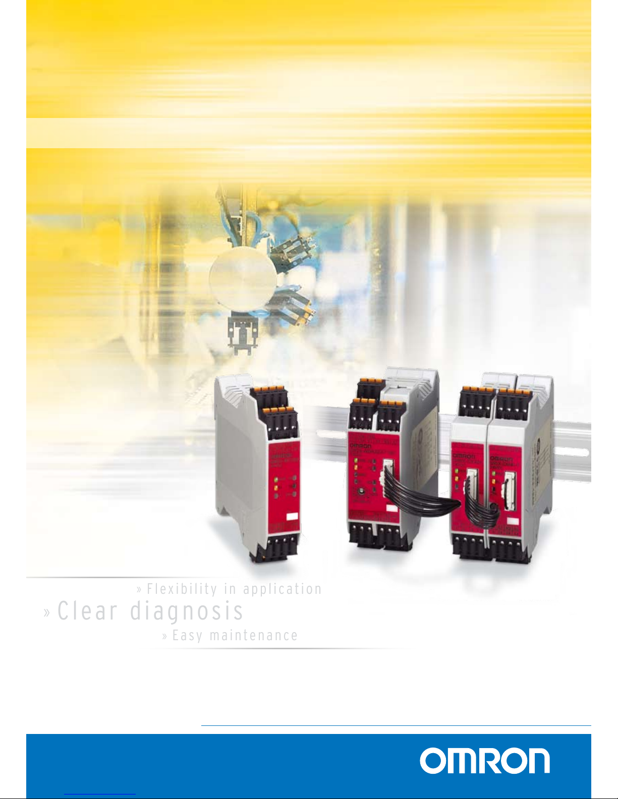
Fl ex i b il i t y i n a p p l i c a t i o n
»
Ea sy m a i n te n a n ce
»
Cle ar d i a g no s i s
G9SX FLEXIBLE SAFETY UNIT
T h e l o g i c a l a l t e r n a t i ve in sa f e ty c o n t r o l
Page 2
The flexible way to design-in safety
The G9SX flexible safety unit provides unique AND connections
for easy, flexible and expandable safety machine control:
Modular - It allows the machine safety function to be split into
separate function blocks for easy diagnosis and maintenance.
Expandable - Existing safety controls with G9SX can be easily
expanded by using additional G9SX units connected by the
logical AND function.
Flexible - The logical AND function offers flexibility for modular
machines, while safety control can be set up individually in
every module. The end result is that modules of machines can
be easily connected by using the AND function to set up the
complete safety function.
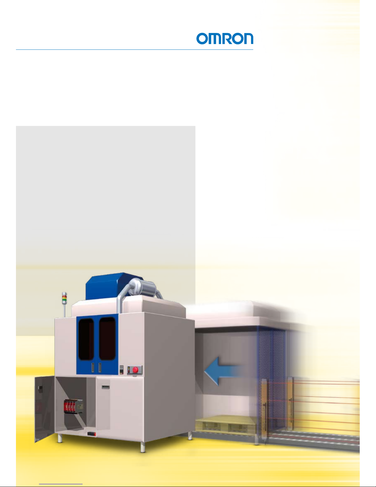
Omron’s G9SX is an innovative flexible safety
unit that provides a clever solution for partial
or complete safeguarding of a machine control
system. Using microprocessor technology, the
G9SX provides a transparent, logical connection
throughout your system that enables you to
shut down any segmentation according to your
machine’s safety layout. Key industries for G9SX
applications are the packaging, semiconductor,
moulding and food processing industries.
Page 3
Advanced Industrial Automation
Basic unit G9SX-BC
• 1 two-channel safety input
• E-Stop applications
• 2 solid state safety outputs (instantaneous)
• 2 logical “AND” outputs
• 2 auxiliary outputs
• 6 LED indicators
• 22.5 mm wide housing
Advanced units G9SX-AD and G9SX-ADA
• 1 two-channel safety input
• Up to 3 solid state safety outputs (instantaneous) and 2 solid
state safety outputs (OFF-delayed up to 15 sec or 150 sec)
• 1 logical “AND” input for G9SX-AD
• 2 logical “AND” inputs for G9SX-ADA
• 1 logical “AND” output for G9SX-AD
• 2 logical “AND” outputs for G9SX-ADA
• 2 auxiliary outputs
• 8 LED indicators
• 35 mm wide housing
Expansion unit G9SX-EX
• 4 safety relay outputs (instantaneous) or 4 safety relay
outputs (OFF-delayed, OFF-delay is controlled by connected
Advanced unit)
• Combination of up to 5 Expansion units is possible to give
25 safety outputs in total
• 1 auxiliary output
• 3 LED indicators
• 22.5 mm wide housing
The G9SX flexible safety unit range
G9SX-BC
G9SX-AD
G9SX-EX
G9SX-EX-T
Page 4

Flexibility and expandability in applications
The G9SX-EX expansion unit has four safety relay outputs.
Up to five expansion units can be easily connected together per
switching path to provide up to 25 outputs if required (20 relay
outputs and five electronic outputs), giving you the highest
system integrity and fail-safe operation for your system.
Unique! Logical connection
The G9SX uses microprocessor technology to manage a unique,
hardwire-based dynamic ‘safety carrier signal’. The ‘safety
carrier signal’ produces an easy parallel-wired structure of
logical AND connections to determine a partial or complete
shutdown. The ‘safety carrier signal’ provides a continuous
system check to ensure safety integrity at all times.
With the logical connection feature, even complex machines
can be easily segmented for more precise shut down during
faultfinding or machine maintenance, with minimum impact on
downtime and productivity. In total, up to 20 units can be
combined using the logical AND connection. Depending on
the safety system, up to five tiers can be set up for individual
stop of machine parts. A maximum of four logical inputs can
be used together with every logical output from Basic units
or Advanced units.
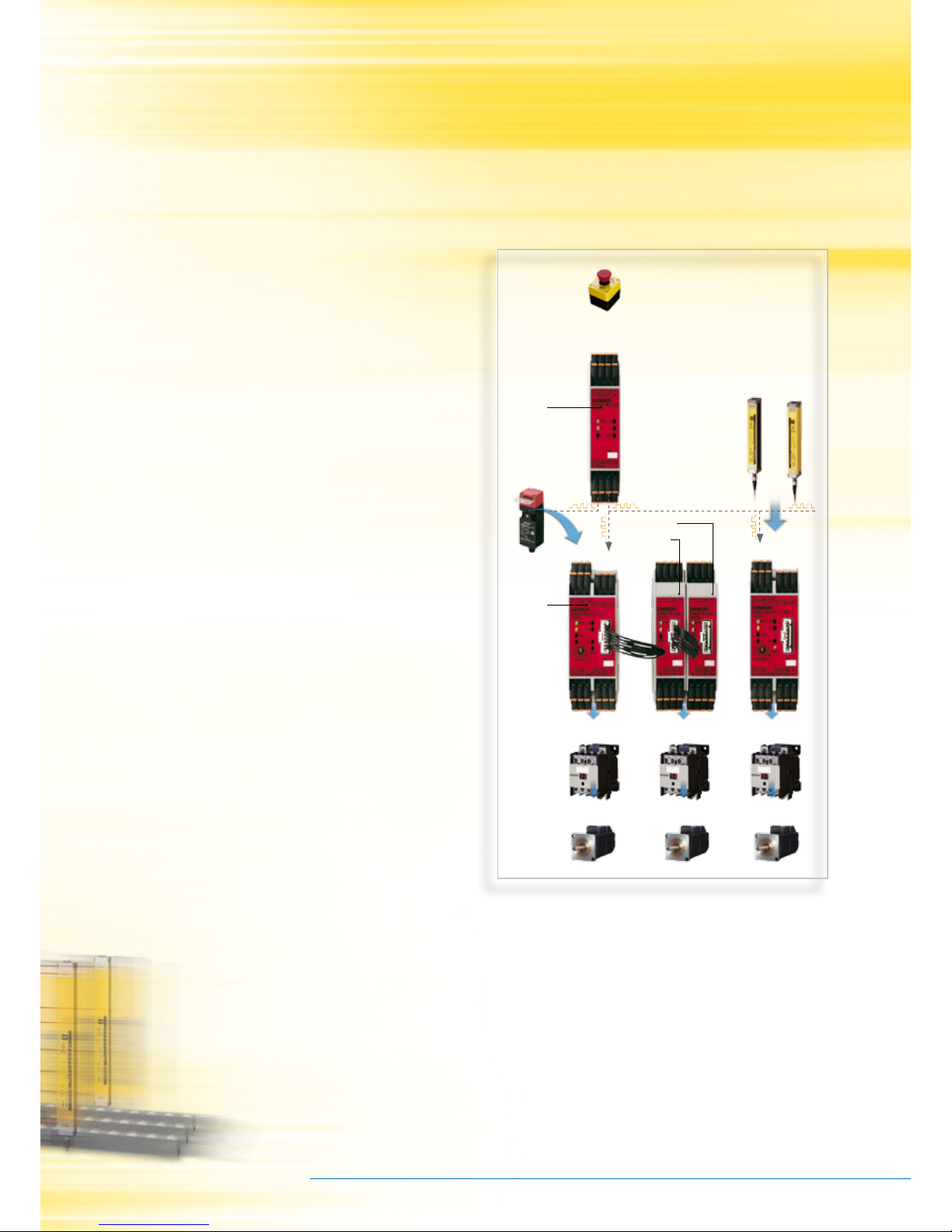
Features and benefits
Machining center example.
In a machining center, for example, when the Emergency Stop
Switch is pressed, the entire machine will stop. When a door
is opened, only the corresponding part will be stopped.
So the safety system of this machine has two tiers as shown
in the drawing below.
Main door
Emergency Stop Switch
Pallet changer door
Tool changer door
Basic Unit
G9SX-BC
Advanced Unit
G9SX-AD
Advanced Unit
G9SX-AD
Advanced Unit
G9SX-AD
Safety Door
Switch
Safety Door
Switch
Safety Door
Switch
Emergency Stop Switch
Logical
connection
Main Door Pallet Changer Door Tool Changer Door
Advanced Unit
G9SX-ADA222-®
Basic Unit
G9SX-BC202-®
Basic Unit
G9SX-BC202-®
a AND b AND c
a
a
b
b
c
Page 5

Advanced Industrial Automation
Extended operating life through solid state outputs
Unlike conventional relays, the safety outputs of the G9SX-BC
and G9SX-AD are solid state, so there are no mechanical parts
to wear out. This design is very effective for frequent
switching cycles.
Advanced diagnostics and troubleshooting functionality
The G9SX features a number of LEDs that indicate the entire
status of the system, including power supply, safety inputs and
outputs, feedback input, logical AND connection, and error
Terminals can be either screw-type or screw-less spring-type. Plug-in wiring connectors are quick and easy to remove, enabling
fast maintenance.
status. This provides a clear image of what’s happening for
easy diagnostics and troubleshooting. The auxiliary outputs
highlight the system status (output and error) to your control
system to provide full transparency and displays where the
fault area occurs.
Easy connectivity
The G9SX offers a choice of terminals: a screw-less spring-type
or screw type. These terminals feature plug-in wiring connectors
that are easily detachable for fast and easy maintenance.
Power supply indicator
Safety input #1 indicator
Logical AND input indicator
Safety output indicator
Safety input #2 indicator
Feedback reset input indicator
OFF-delayed safety output indicator
Error indicator
Logical AND input indicator
Page 6

For full specifications and additional models please refer to www.omron-industrial.com
Safety network and units - Cat.-No. J150-E2-04
1
G9SX
Safety network and units
Flexible safety unit
G9SX-family modules can be connected by a logical "AND" function to
implement partial/global stopping of a machine. Solid-state outputs,
detailed LED diagnosis and clever feedback signals help to keep
maintenance easy. The line-up is completed by expansion units with
safe timing functions.
• Clear and transparent segmentation of safety functions by use of
unique "AND" connection
• Solid-state outputs for long life and relay outputs in extension box
available
• Detailed LED indications enable easy diagnosis
• Clever feedback signals for easy maintenance
• Category 4 according to EN954-1 and SIL 3 according to EN 61508
Ordering information
Advanced unit 1 logical AND input
Advanced unit 2 logical AND inputs
Basic unit
Expansion unit
Specifications
Power input Inputs
Outputs
Safety outputs Auxiliary outputs No. of input
channels
Max. OFFdelay time
*1
*1
The OFF-delay time can be set in 16 steps as follows: T15: 0/0.2/0.3/0.4/0.5/0.6/0.7/1/1.5/2/3/4/5/7/10/15 s, T150: 0/10/20/30/40/50/60/70/80/90/100/110/120/130/
140/150
Rated
voltage
Terminal block type Model
Instantaneous OFF-delayed
P channel MOS-FET
transistor output
P channel MOS FET
transistor outputs
PNP transistor
outputs
1 or 2 channels 0 to 15 s in
16 steps
24 VDC Screw terminals G9SX-AD322-T15-RT
Cage clamp terminals G9SX-AD322-T15-RC
0 to 150 s in
16 steps
Screw terminals G9SX-AD322-T150-RT
Cage clamp terminals G9SX-AD322-T150-RC
Safety outputs Auxiliary outputs No. of input
channels
Max. OFFdelay time
*1
*1
The OFF-delay time can be set in 16 steps as follows: T15: 0/0.2/0.3/0.4/0.5/0.6/0.7/1/1.5/2/3/4/5/7/10/15 s, T150: 0/10/20/30/40/50/60/70/80/90/100/110/120/130/
140/150
Rated
voltage
Terminal block type Model
Instantaneous OFF-delayed
P channel MOS-FET
transistor output
P channel MOS FET
transistor outputs
PNP transistor
outputs
1 or 2 channels 0 to 15 s in
16 steps
24 VDC Screw terminals G9SX-ADA222-T15-RT
Cage clamp terminals G9SX-ADA222-T15-RC
0 to 150 s in
16 steps
Screw terminals G9SX-ADA222-T150-RT
Cage clamp terminals G9SX-ADA222-T150-RC
Safety outputs Auxiliary outputs No. of input
channels
Rated voltage Terminal block type Model
Instantaneous OFF-delayed
P channel MOS FET
transistor output
--- PNP transistor output 1 or 2 channels 24 VDC Screw terminals G9SX-BC202-RT
Cage clamp terminals G9SX-BC202-RC
Safety outputs Auxiliary outputs OFF-delay time Rated voltage Terminal block type Model
Instantaneous OFF-delayed
4 PST-NO (contact) --- 1 (solid state)
PNP transistor output
--- 24 VDC Screw terminals G9SX-EX401-RT
Cage clamp terminals G9SX-EX401-RC
--- 4 PST-NO (contact) Synchronized
with
G9SX-AD - unit
Screw terminals G9SX-EX041-T-RT
Cage clamp terminals G9SX-EX041-T-RC
Item G9SX-AD322-@
G9SX-ADA222-@
G9SX-BC202-@ G9SX-EX-@
Rated supply voltage 20.4 to 26.4 VDC (24 VDC -15% +10%)
Item G9SX-AD322-@
G9SX-ADA222-@
G9SX-BC202-@
Safety input Operating voltage: 20.4 VDC to 26.4 VDC,
internal impedance: approx. 2.8 kΩ
Feedback/reset input
Item G9SX-AD322-@
G9SX-ADA222-@
G9SX-BC202-@
Instantaneous safety output
OFF-delayed safety output
P channel MOS FET transistor output
Load current: Using 2 outputs or less: 1 A DC max.
Using 3 outputs or more: 0.8 A DC max.
P channel MOS FET transistor output
Load current: Using 1 output: 1 A DC max.
Using 2 outputs: 0.8 A DC max.
Auxiliary output PNP transistor output
Load current: 100 mA max.
LISTED
Safety network and units6
For full specifications and additional models please refer to www.omron-industrial.com
Safety network and units - Cat.-No. J150-E2-04
Page 7

G9SX
Safety network and units
2
Expansion unit
Characteristics
Connections
Internal Connection
G9SX-AD322-@ (Advanced Unit)
G9SX-BC202-@ (Basic Unit)
G9SX-EX401-@/G9SX-EX041-T-@ (Expansion
Unit / Expansion Unit OFF-delayed model)
G9SX-ADA222-@ (Advanced Unit)
Item G9SX-EX-@
Rated load 250 VAC, 3A / 30 VDC, 3A
(resistive load)
Rated carry current 3 A
Maximum switching voltage 250 VAC, 125 VDC
Item G9SX-AD322-@
G9SX-ADA222-@
G9SX-BC202-@ G9SX-EX-@
Operating time (OFF to ON state) 50 ms max. (Safety input: ON)
100 ms max.
(Logical AND connection input: ON)
50 ms max. (Safety input: ON) 30 ms max.
Response time (ON to OFF state) 15 ms max. 10 ms max.
Durability Electrical --- 100,000 cycles min.
Mechanical --- 5,000,000 cycles min.
Ambient temperature -10 °C +55 °C (with no icing or condensation)
(See
note 1.)
(See note 2.)
S14A2S24 S34 S44 S54
L1 X1 X2
Power
supply
circuit
Safety
Input 1
Safety
Input 2
Reset/Feedback
Input
Cross
fault
detection
input
Safety output control
Auxiliary
output control
Logical AND input
Expansion Unit
output control
T11A1 T12 T21 T22 T31 T32 T33 Y1 T41 T42
(See note 3.)
Note: 1. Internal power supply circuit is not isolated.
2. Logical AND input is isolated.
3. Outputs S14 to S54 are internally redundant.
(See
note 1.)
Reset/Feedback
Input
S14A2S24 L1 L2
X1 X2
Safety
Input 1
Safety
Input 2
Safety outputs control
T11A1T12 T21 T22 T31 T32 T33
Y1
Power
supply
circuit
Cross
fault
detection
input
Auxiliary
output control
(See note 2.)
Note: 1. Internal power supply circuit is not isolated.
2. Outputs S14 to S24 are internally redundant.
A2 X2
Safety
output
control
A1
K1
13 23 33 43
14 24 34 44
K2
Exp.
sig.
IN
Exp.
sig.
OUT
(See
note 1.)
(See note 2.)
Power
supply
circuit
Auxiliary
output
control
Note: 1. Internal power supply circuit is not isolated.
2. Relay outputs are isolated.
S14A2S24 S44 S54
L1 L2 X1 X2
Power
supply
circuit
Safety
Input 1
Safety
Input 2
Reset/Feedback
Input
Safety output control
Logical
AND input
T11A1 T12 T21 T22 T31 T32 T33 Y1
T41 T42 T51 T52
Logical
AND input 2
(See
note 1.)
(See
note
2.)
Cross
fault
detection
input
Auxiliary
output control
Expansion Unit
output control
(See note 3.)
Note: 1. Internal power supply circuit is not isolated.
2. Logical AND input are isolated.
3. Outputs S14 to S54 are internally redundant.
G9SX 7
Page 8

Austria
Tel: +43 (0) 1 80 19 00
www.omron.at
Belgium
Tel: +32 (0) 2 466 24 80
www.omron.be
Czech Republic
Tel: +420 234 602 602
www.omron.cz
Denmark
Tel: +45 43 44 00 11
www.omron.dk
Finland
Tel: +358 (0) 207 464 200
www.omron.fi
France
Tel: +33 (0) 1 56 63 70 00
www.omron.fr
Germany
Tel: +49 (0) 2173 680 00
www.omron.de
Hungary
Tel: +36 (0) 1 399 30 50
www.omron.hu
Italy
Tel: +39 02 326 81
www.omron.it
Middle East & Africa
Tel: +31 (0) 23 568 11 00
www.omron-industrial.com
Netherlands
Tel: +31 (0) 23 568 11 00
www.omron.nl
Norway
Tel: +47 (0) 22 65 75 00
www.omron.no
Poland
Tel: +48 (0) 22 645 78 60
www.omron.pl
Portugal
Tel: +351 21 942 94 00
www.omron.pt
Russia
Tel: +7 495 745 26 64
www.omron.ru
Spain
Tel: +34 913 777 900
www.omron.es
Sweden
Tel: +46 (0) 8 632 35 00
www.omron.se
Switzerland
Tel: +41 (0) 41 748 13 13
www.omron.ch
Turkey
Tel: +90 (0) 216 474 00 40
www.omron.com.tr
United Kingdom
Tel: +44 (0) 870 752 08 61
www.omron.co.uk
Control Systems
• Programmable logic controllers • Human-machine interfaces • Remote I/O
Motion & Drives
• Motion controllers • Servo systems • Inverters
Control Components
• Temperature controllers • Power supplies • Timers • Counters • Programmable relays
• Digital panel indicators • Electromechanical relays • Monitoring products • Solid-state relays
• Limit switches • Pushbutton switches • Low voltage switch gear
Sensing & Safety
• Photoelectric sensors • Inductive sensors • Capacitive & pressure sensors • Cable connectors
• Displacement & width-measuring sensors • Vision systems • Safety networks • Safety sensors
• Safety units/relay units • Safety door/guard lock switches
Aut hori sed Distri butor:
G9SX_01_EN_INT
Although we strive for perfection, Omron Europe BV and/or its subsidiary and affiliated companies do not warrant
or make any representations regarding the correctness or completeness of the information described in this document.
We reserve the right to make any changes at any time without prior notice.
OMRON EUROPE B.V.
Wegalaan 67-69, NL-2132 JD, Hoofddorp, The Netherlands. Tel: +31 (0) 23 568 13 00 Fax: +31 (0) 23 568 13 88 www.omron-industrial.com
More Omron representatives
www.omron-industrial.com
 Loading...