

Omron E5CSV-R1T-500, E5CSV-Q1T-500, E5CSV-R1TD-500, E5CSV-Q1TD-500 Datasheet
Temperature Controllers E5CSV 1
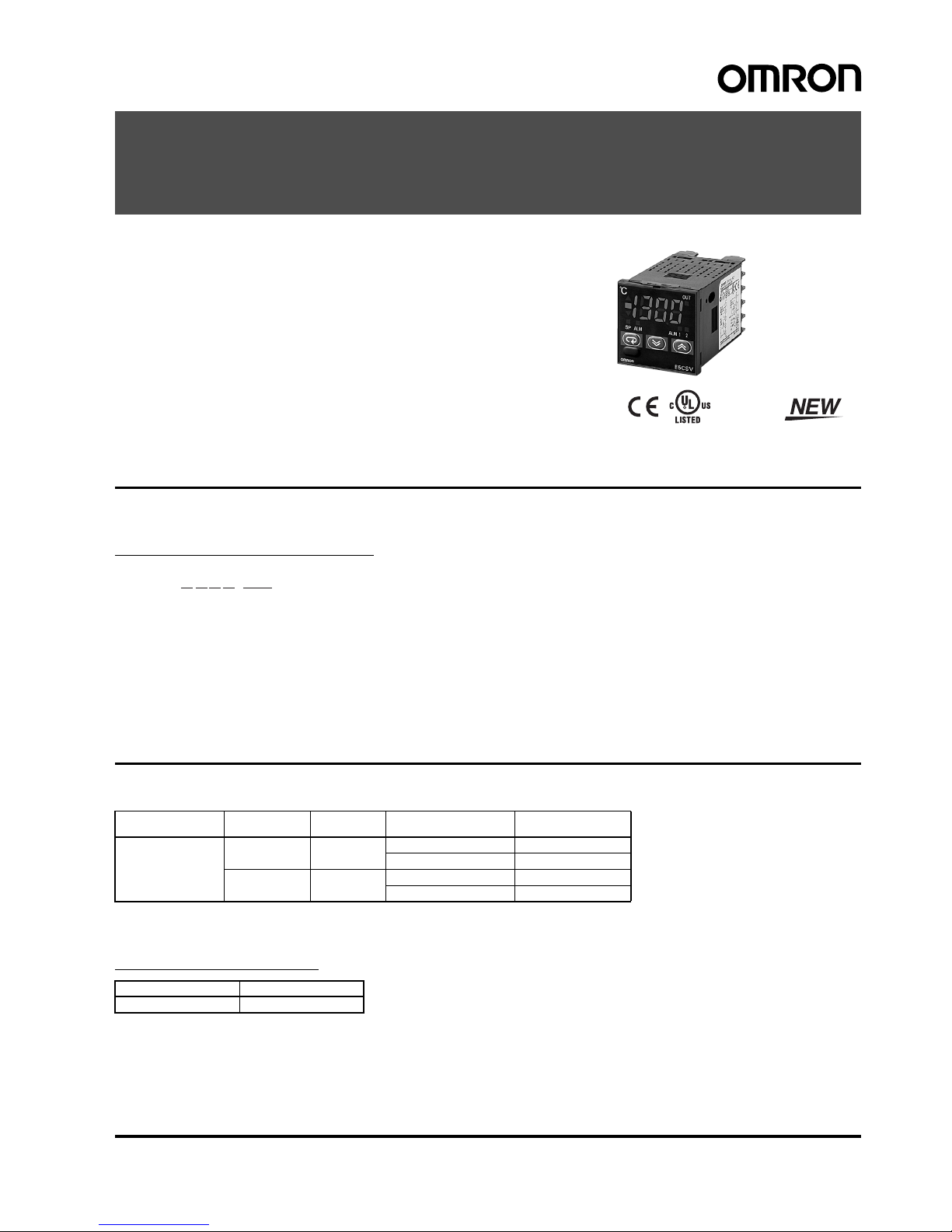
Temperature Controllers
E5CSV
Easy Setting Using DIP Switch and Simple
Functions in DIN 48 x 48 mm-size
Temperature Controllers
• Easy setting using DIP and rotary switches.
• Multi-input (thermocouple/platinum resistance thermometer).
• Clearly visible digital display with character height of 13.5 mm.
• RoHS compliant.
Model Number Structure
■ Model Number Legend
Models with Terminal Blocks
1. Output type
R: Relay
Q: Voltage for driving SSR
2. Number of alarms
1: 1 alarm
3. Input type
T: Thermocouple/platinum resistance
thermometer (multi-input)
4. Power supply voltage
Blank: 100 to 240 VAC
D: 24 VAC/VDC
5. Terminal cover
500: Finger protection cover
Ordering Information
■ List of Models
■ Accessories (Order Separately)
Protective Front Cover
1 2 3 4 5
E5CSV-@1T@-500
Size Power supply
voltage
Number of
alarm points
Control output TC/Pt multi-input
Incl. terminal cover
1/16 DIN
48 x 48 x 78 mm
(W x H x D)
100 to 240 VAC 1 Relay E5CSV-R1T-500
Voltage (for driving SSR) E5CSV-Q1T-500
24 VAC/VDC 1 Relay E5CSV-R1TD-500
Voltage (for driving SSR) E5CSV-Q1TD-500
Type Model
Hard Protective Cover Y92A-48B
2 Temperature Controllers E5CSV
Specifications
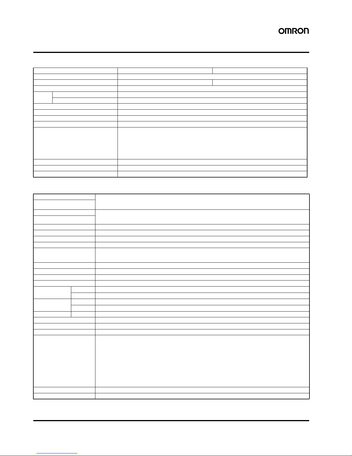
■ Ratings
■ Characteristics
Note: 1. The following exceptions apply to thermocouples.
• U, L: ±2°C ±1 digit max.
• R: ±3° C ±1 digit max. at 200° C or less
2. The following exceptions apply to platinum resistance
thermometers.
Input set values 0, 1, 2, 3 for E5CSV: 0.5% FS ±1 digit max.
Input set value 1 for E5CSV: 0.5% FS ±1 digit max.
Supply voltage 100 to 240 VAC, 50/60 Hz 24 VAC/VDC, 50/60 Hz
Operating voltage range 85% to 110% of rated supply voltage
Power consumption 5 VA 3 VA/2 W
Sensor input Multi-input (thermocouple/platinum resistance thermometer) type: K, J, L, T, U, N, R, Pt100, JPt100
Control
output
Relay output SPST-NO, 250 VAC, 3A (resistive load)
Voltage output (for driving the SSR) 12 VDC, 21 mA (with short-circuit protection circuit)
Control method ON/OFF or 2-PID (with auto-tuning)
Alarm output SPST-NO, 250 VAC, 1A (resistive load)
Setting method Digital setting using front panel keys (functionality set-up with DIP switch)
Indication method 3.5 digit, 7-segment digital display (character height: 13.5 mm) and deviation indicators
Other functions • Setting change prohibit (key protection)
• Input shift
• Temperature unit change (°C/° F)
• Direct/reverse operation
• Control period switching
• 8-mode alarm output
• Sensor error detection
Ambient temperature -10 to 55° C (with no condensation or icing)
Ambient humidity 25% to 85%
Storage temperature -25 to 65° C (with no condensation or icing)
Setting accuracy Thermocouple (See note 1.): (±0.5% of indication value or ±1°C, whichever is greater) ±1 digit max.
Platinum resistance thermometer (See note 2.): (±0.5% of indication value or ±1°C, whichever is greater) ±1 digit max.
Indication accuracy
(ambient temperature of 23°C)
Influence of temperature R thermocouple inputs: (±1% of PV or ±10°C, whichever is greater) ±1 digit max.
Other thermocouple inputs: (±1% of PV or ±4°C, whichever is greater) ±1 digit max.
Platinum resistance thermometer inputs: (±1% of PV or ±2° C, whichever is greater) ±1 digit max.
Influence of voltage
Hysteresis (for ON/OFF control) 0.1% FS
Proportional band (P) 1 to 999° C (automatic adjustment using auto-tuning/self-tuning)
Integral time (I) 1 to 1,999 s (automatic adjustment using auto-tuning/self-tuning
Derivative time (D) 1 to 1,999 s (automatic adjustment using auto-tuning/self-tuning)
Alarm output range Absolute-value alarm: Same as the control range
Other: 0% to 100% FS
Alarm hysteresis: 0.2° C or ° F (fixed)
Control period 2/20 s
Sampling period 500 ms
Insulation resistance 20 MΩ min. (at 500 VDC)
Dielectric strength 2,000 VAC, 50/60 Hz for 1 min between current-carrying terminals of different polarity
Vibration
resistance
Malfunction
10 to 55 Hz, 20 m/s
2
for 10 min each in X, Y, and Z directions
Destruction 10 to 55 Hz, 0.75-mm single amplitude for 2 hr each in X, Y, and Z directions
Shock resistance Malfunction
100 m/s
2
min., 3 times each in 6 directions
Destruction
300 m/s
2
min., 3 times each in 6 directions
Life expectancy Electrical 100,000 operations min. (relay output models)
Weight Approx. 120 g (Controller only)
Degree of protection Front panel: Equivalent to IP66; Rear case: IP20; Terminals: IP00
Memory protection EEPROM (non-volatile memory) (number of writes: 1,000,000)
EMC EMI Radiated: EN 55011 Group 1 Class A
EMI Conducted: EN 55011 Group 1 Class A
ESD Immunity: EN 61000-4-2: 4 kV contact discharge (level 2)
8 kV air discharge (level 3)
Radiated Electromagnetic Field Immunity: EN 61000-4-3: 10 V/m (80-1000 MHz, 1.4-2.0 GHz amplitude modulated) (level 3)
10 V/m (900 MHz pulse modulated)
Conducted Disturbance Immunity: EN 61000-4-6: 3 V (0.15 to 80 MHz) (level 2)
Noise Immunity (First Transient Burst Noise): EN 61000-4-4
Burst Immunity: 2 kV power-line (level 3), 1 kV I/O signal-line (level 3)
Surge Immunity: EN 61000-4-5: Power line: Normal mode 1 kV; Common mode 2 kV
Output line (relay output): Normal mode 1 kV; Common mode 2 kV
Voltage Dip/Interrupting Immunity: EN 61000-4-11 0.5 cycle, 100% (rated voltage)
Approved standards UL 61010C-1 (listing), CSA C22.2 No.1010-1
Conformed standards EN 61326, EN 61010-1, IEC 61010-1, VDE 0106 Part 100 (finger protection), when the terminal cover is mounted.
Temperature Controllers E5CSV 3
Installation
• All models in the E5CSV Series conform to DIN 43700 standards.
• The recommended panel thickness is 1 to 4 mm.
• Be sure to mount the E5CSV horizontally.
Mounting the E5CSV
1. For waterproof mounting, waterproof packing must be installed on the Controller. Waterproofing is not possible when group mounting several
Controllers.
2. Insert the E5CSV into the mounting hole in the panel.
3. Push the adapter from the terminals up to the panel, and temporarily fasten the E5CSV.
4. Tighten the two fastening screws on the adapter. Alternately tighten the two screws little by little to maintain a balance. Tighten the screws to a
torque of 0.29 to 0.39 N·m.
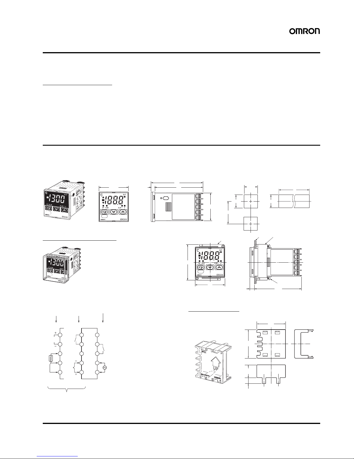
Dimensions
Note: All units are in millimeters unless otherwise indicated.
■ Controller
Terminal Cover
Note: 1. The voltage output (12 VDC, 21 mA) is not electrically isolated from the internal circuits. When using a grounding thermocouple, do not
connect output terminals 1 or 2 to ground. Otherwise, unwanted current paths will cause measurement errors.
2. Models with 100 to 240 VAC and 24 VAC/VDC are separate. Models using 24 VDC have no polarity.
Panel Cutout Dimensions
44.8×44.8
84
786
48×48
60 min.
L = (48 × N−2.5)
+1
0
Mounting side-by-side
(group mounting of N Controllers)
45
+0.6
0
45
+0.6
0
45
+0.6
0
L
Tightening
screws
48
76.5
7.5
Adapter for flush mounting
Panel
Y92F-30 Adapter for flush mounting
58
E5CSV
Note: 1. The recommended panel thickness is 1 to 4 mm.
2. Group mounting is possible in one direction only.
Note: Terminals cannot be removed.
Hard Protective Cover
The Y92A-48B Protective Cover (hard type) is
available for the following applications.
• To protect the set from dust and dirt.
• To prevent the panel from being accidentally
touched causing displacement of set values.
• To provide effective protection against water
droplets.
°C
92A-48B
92A -48 B
92A-48B
8
9
10
7
6
3
4
5
2
11
2
1
2
3
4
5
12 VDC,
21 mA
Alarm output
Alarm output 1
Relay output
models
Voltage output
models
(See note 1.)
Thermocouple/
platinum resistance thermometer multi-input
100 to 240 VAC, 50/60 Hz
(24 VAC/VDC)
(See note 2.)
A
B
B
Thermocouple
input
Relay outputVoltage output
Platinum resistance
thermometer input
48
48.8
22
9.1
E53-COV10
4 Temperature Controllers E5CSV
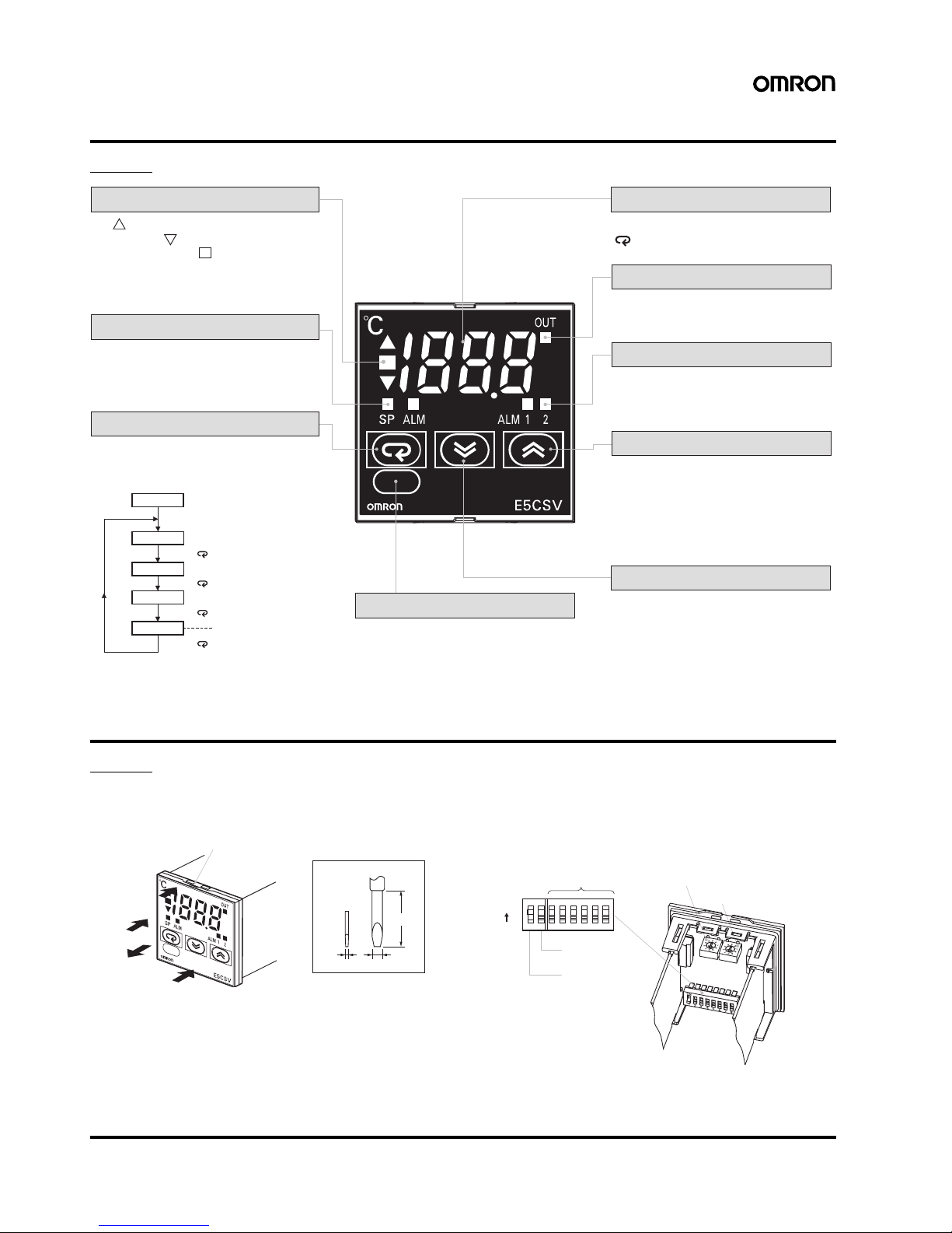
Operation
E5CSV
Settings before Turning ON the Power
E5CSV
Remove the E5CSV from the case to make the settings.
1. Insert the tool into the two tool insertion holes (one on the top and
one on the bottom) and release the hooks.
2. Insert the tool in the gap between the front panel and rear case,
and pull out the front panel slightly. Grip the front panel and pull
out fully. Be sure not to impose excessive force on the panel.
3. When inserting the E5CSV, check to make sure that the sealing
rubber is in place and push the E5CSV toward the rear case until
it snaps into position. While pushing the E5CSV into place, push
down on the hooks on the top and bottom surfaces of the rear
case so that the hooks are securely locked in place. Make sure
that electronic components do not come into contact with the
case.
Note: 1. The INIT switch is always OFF during normal operation.
Deviation indicators
The indicator lights when the PV is greater than
the SP and the indicator lights when the PV is
less than the SP. The indicator (green) lights
when the deviation is less than 1% FS (0.25% FS
for multi-input models). These indicators flash
during ST (self-tuning)/AT (auto-tuning).
Mode indicators
The SP indicator lights when the setting
temperature is being displayed. The ALM
indicator lights when the alarm value 1 is
being displayed.
PV, SP, Alarm Value, Input Shift Display
Alarm indicators
ALM1 (Alarm 1): Lights when the alarm 1
output is ON.
ALM2 (Alarm 2): For future use.
Up Key
Pressing the Up Key increases the
SP/alarm value display. Keeping the Up
Key pressed continues to increase the
display value. When the internal protect
switch is ON, press the Up Key while
holding down the Lock Release Key.
Output indicator
Lights when the control output is ON.
The display switches each time the
Key is pressed.
Lock Release Key
When the protect switch is ON, the set
value can be changed by pressing the Up
and Down Keys while holding down the
Lock Release Key.
Down Key
Pressing the Down Key decreases the
SP/alarm value display. Keeping the Down
Key pressed continues to decrease the
display value. When the internal protect
switch is ON, press the Down Key while
holding down the Lock Release Key.
When the power is turned ON, normally the
display will use the display items in the following
order each time the Mode Key is pressed.
Mode Key
PV
SP
Alarm value 1
Input shift value
Power ON
Press the Key.
Press the Key.
Press the Key.
Press the Key.
This item is not displayed when
the Control Mode Switch 4 is OFF.
Flat-blade screwdriver
(Unit: mm)
(1)
(1)
(2)
(3)
Tool insertion hole
0.4 2.0
20 min.
PONX123456
Alarm mode switch (See note 1.)
Temperature range switch
Control mode switches
INIT switch
(See note 2.)
Protect switch
ON
 Loading...