

Page 1

Cat. No. W394-E1-13
SYSMAC CS Series
SYSMAC CJ Series
SYSMAC One NSJ Series
Programmable Controllers
PROGRAMMING MANUAL
Page 2

Page 3

SYSMAC CS Series
CS1G/H-CPU@@-EV1
CS1G/H-CPU@@H
CS1D-CPU@@H
CS1D-CPU@@S
SYSMAC CJ Series
CJ1H-CPU@@H-R
CJ1G-CPU@@
CJ1G/H-CPU@@H
CJ1G-CPU@@P
CJ1M-CPU@@
SYSMAC One NSJ Series
Programmable Controllers
Programming Manual
Revised August 2008
Page 4

iv
Page 5

Notice:
r
f
OMRON products are manufactured for use according to proper procedures
by a qualified operator and only for the purposes described in this manual.
The following conventions are used to indicate and classify precautions in this
manual. Always heed the information provided with them. Failure to heed precautions can result in injury to people or damage to property.
!DANGER Indicates an imminently hazardous situation which, if not avoided, will result in death or
serious injury. Additionally, there may be severe property damage.
!WARNING Indicates a potentially hazardous situation which, if not avoided, could result in death or
serious injury. Additionally, there may be severe property damage.
!Caution Indicates a potentially hazardous situation which, if not avoided, may result in minor or
moderate injury, or property damage.
OMRON Product References
All OMRON products are capitalized in this manual. The word “Unit” is also
capitalized when it refers to an OMRON product, regardless of whether or not
it appears in the proper name of the product.
The abbreviation “Ch,” which appears in some displays and on some OMRON
products, often means “word” and is abbreviated “Wd” in documentation in
this sense.
The abbreviation “PLC” means Programmable Controller. “PC” is used, however, in some Programming Device displays to mean Programmable Controller.
Visual Aids
OMRON, 2001
All rights reserved. No part of this publication may be reproduced, stored in a retrieval system, or transmitted, in any form, o
by any means, mechanical, electronic, photocopying, recording, or otherwise, without the prior written permission o
OMRON.
No patent liability is assumed with respect to the use of the information contained herein. Moreover, because OMRON is constantly striving to improve its high-quality products, the information contained in this manual is subject to change without
notice. Every precaution has been taken in the preparation of this manual. Nevertheless, OMRON assumes no responsibility
for errors or omissions. Neither is any liability assumed for damages resulting from the use of the information contained in
this publication.
The following headings appear in the left column of the manual to help you
locate different types of information.
Note Indicates information of particular interest for efficient and convenient opera-
tion of the product.
1,2,3... 1. Indicates lists of one sort or another, such as procedures, checklists, etc.
v
Page 6
Unit Versions of CS/CJ-series CPU Units
Unit Versions A “unit version” has been introduced to manage CPU Units in the CS/CJ
Series according to differences in functionality accompanying Unit upgrades.
This applies to the CS1-H, CJ1-H, CJ1M, and CS1D CPU Units.
Notation of Unit Versions
on Products
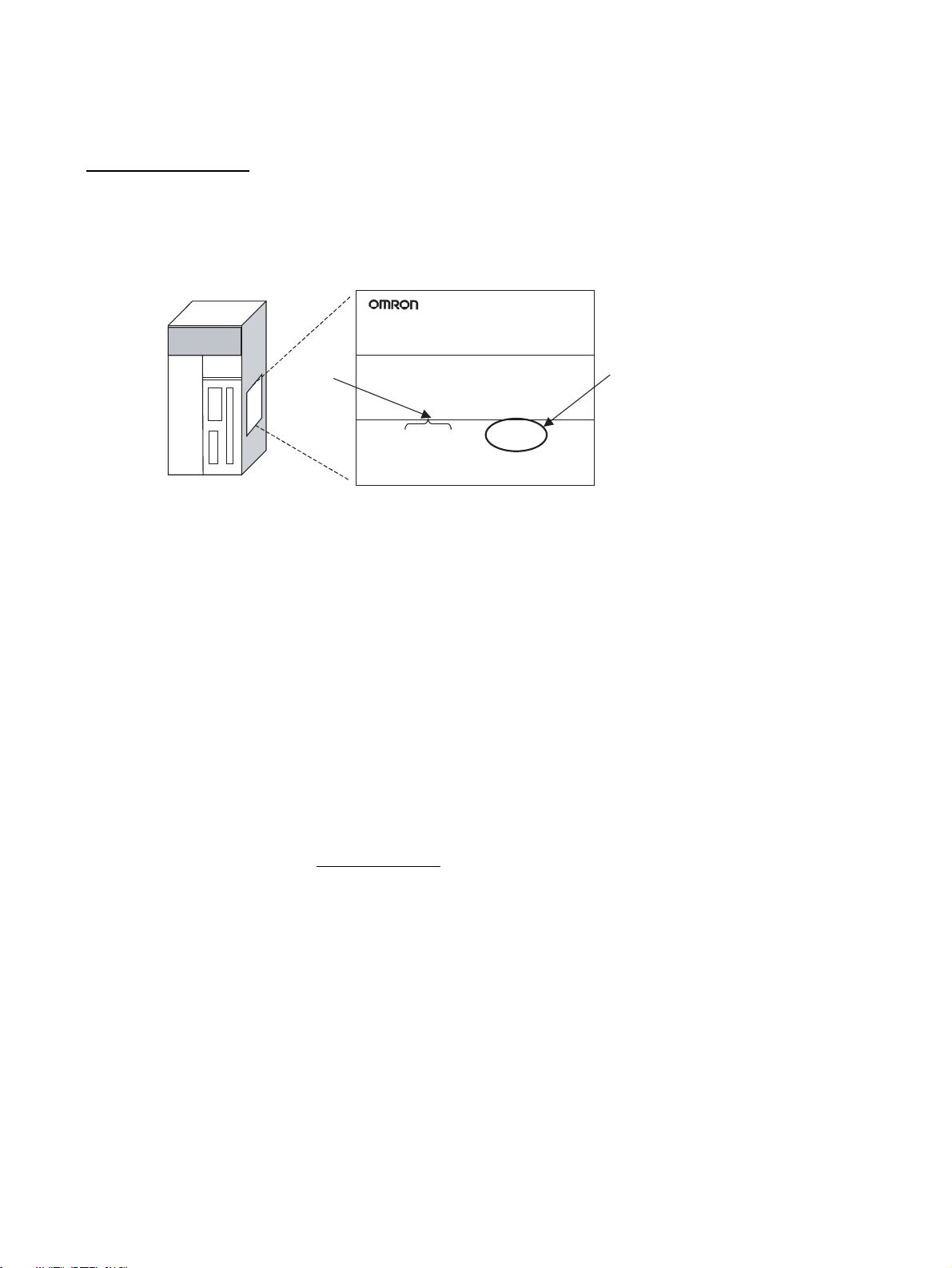
CS/CJ-series CPU Unit
The unit version is given to the right of the lot number on the nameplate of the
products for which unit versions are being managed, as shown below.
Product nameplate
CS1H-CPU67H
CPU UNIT
Lot No.
Lot No. 040715 0000 Ver.3.0
OMRON Corporation MADE IN JAPAN
Unit version
Example for Unit version 3.0
• CS1-H, CJ1-H, and CJ1M CPU Units manufactured on or before November 4, 2003 do not have a unit version given on the CPU Unit (i.e., the
location for the unit version shown above is blank).
• The unit version of the CJ1-H-R CPU Units begins at version 4.0.
• The unit version of the CS1-H, CJ1-H, and CJ1M CPU Units, as well as
the CS1D CPU Units for Single-CPU Systems, begins at version 2.0.
• The unit version of the CS1D CPU Units for Duplex-CPU Systems, begins
at version 1.1.
• CPU Units for which a unit version is not given are called Pre-Ver. @.@
CPU Units, such as Pre-Ver. 2.0 CPU Units and Pre-Ver. 1.1 CPU Units.
Confirming Unit Versions
with Support Software
CX-Programmer version 4.0 can be used to confirm the unit version using one
of the following two methods.
• Using the PLC Information
• Using the Unit Manufacturing Information (This method can be used for
Special I/O Units and CPU Bus Units as well.)
Note CX-Programmer version 3.3 or lower cannot be used to confirm unit versions.
PLC Information
• If you know the device type and CPU type, select them in the Change
PLC Dialog Box, go online, and select PLC - Edit - Information from the
menus.
• If you don't know the device type and CPU type, but are connected
directly to the CPU Unit on a serial line, select PLC - Auto Online to go
online, and then select PLC - Edit - Information from the menus.
In either case, the following PLC Information Dialog Box will be displayed.
vi
Page 7
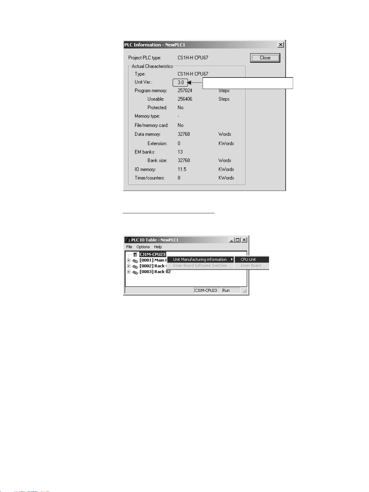
Unit version
Use the above display to confirm the unit version of the CPU Unit.
Unit Manufacturing Information
In the IO Table Window, right-click and select Unit Manufacturing information - CPU Unit.
The following Unit Manufacturing information Dialog Box will be displayed.
vii
Page 8
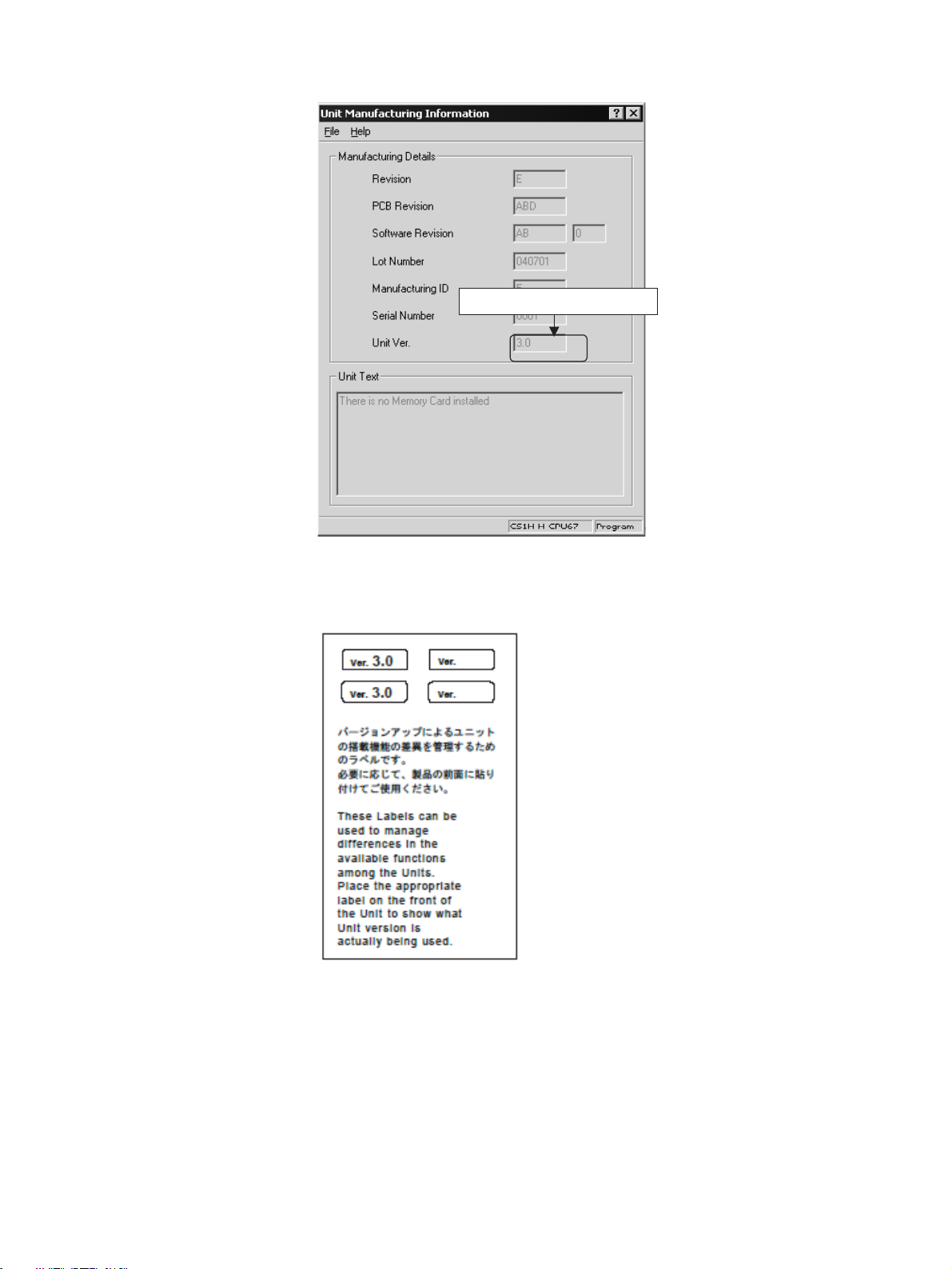
Unit version
Use the above display to confirm the unit version of the CPU Unit connected
online.
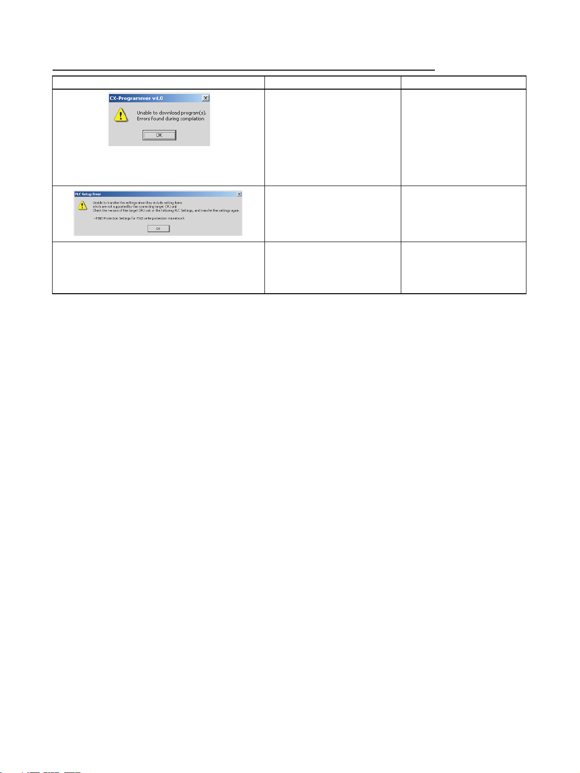
Using the Unit Version
Labels
The following unit version labels are provided with the CPU Unit.
These labels can be attached to the front of previous CPU Units to differentiate between CPU Units of different unit versions.
viii
Page 9

Unit Version Notation In this manual, the unit version of a CPU Unit is given as shown in the follow-
ing table.
Product nameplate
Meaning
Designating individual
CPU Units (e.g., the
CS1H-CPU67H)
Designating groups of
CPU Units (e.g., the
CS1-H CPU Units)
Designating an entire
series of CPU Units
(e.g., the CS-series CPU
Units)
CPU Units on which no unit version is
given
Lot No. XXXXXX XXXX
OMRON Corporation MADE IN JAPAN
Pre-Ver. 2.0 CS1-H CPU Units CS1H-CPU67H CPU Unit Ver. @.@
Pre-Ver. 2.0 CS1-H CPU Units CS1-H CPU Units Ver. @.@
Pre-Ver. 2.0 CS-series CPU Units CS-series CPU Units Ver. @.@
Units on which a version is given
Lot No. XXXXXX XXXX
(Ver. @.@)
Ver. @ @ .@
ix
Page 10

Unit Versions
CS Series
Units Models Unit version
CS1-H CPU Units CS1@-CPU@@H Unit version 4.1
Unit version 4.0
Unit version 3.0
Unit version 2.0
Pre-Ver. 2.0
CS1D CPU Units Duplex-CPU Systems
CS1D-CPU@@H
Single-CPU Systems
CS1D-CPU@@S
CS1 CPU Units CS1@-CPU@@ No unit version.
CS1 Version-1 CPU Units
CS1@-CPU@@-V1 No unit version.
CJ Series
Units Models Unit version
CJ1-H CPU Units CJ1H-CPU@@H-R Unit version 4.2
CJ1@-CPU@@H
CJ1@-CPU@@P
CJ1M CPU Units
CJ1M-CPU12/13
CJ1M-CPU22/23
CJ1M-CPU11/21 Unit version 4.0
Unit version 1.2
Unit version 1.1
Pre-Ver. 1.1
Unit version 2.0
Unit version 4.1
Unit version 4.0
Unit version 4.0
Unit version 3.0
Unit version 2.0
Pre-Ver. 2.0
Unit version 4.0
Unit version 3.0
Unit version 2.0
Pre-Ver. 2.0
Unit version 3.0
Unit version 2.0
NSJ Series
Units Unit version
NSJ@-TQ@@(B)-G5D
NSJ@-TQ@@(B)-M3D
x
Unit version 3.0
Page 11

Function Support by Unit Version
• Functions Supported for Unit Version 4.0 or Later
CX-Programmer 7.0 or higher must be used to enable using the functions
added for unit version 4.0.
Additional functions are supported if CX-Programmer version 7.2 or higher is
used.
CS1-H CPU Units
Function CS1@-CPU@@H
Unit version 4.0 or later Other unit versions
Online editing of function blocks
Note This function cannot be used for simulations on the CX-Simulator.
Input-output variables in function blocks OK --Text strings in function blocks OK --New application
instructions
ST programming in task programs OK with CX-Program-
SFC programming in task programs OK with CX-Program-
Number-Text String Conversion Instructions:
NUM4, NUM8, NUM16, STR4, STR8, and STR16
TEXT FILE WRITE (TWRIT) OK ---
OK ---
OK ---
mer version 7.2 or higher
mer version 7.2 or higher
---
---
CS1D CPU Units
Unit version 4.0 is not supported.
CJ1-H/CJ1M CPU Units
Function CJ1H-CPU@@H-R, CJ1@-CPU@@H,
CJ1G-CPU@@P, C J1 M - C P U @@
Unit version 4.0 or later Other unit versions
Online editing of function blocks
Note This function cannot be used for simulations on the CX-Simulator.
Input-output variables in function blocks OK --Text strings in function blocks OK --New application
instructions
ST programming in task programs OK with CX-Program-
SFC programming in task programs OK with CX-Program-
Number-Text String Conversion Instructions:
NUM4, NUM8, NUM16, STR4, STR8, and STR16
TEXT FILE WRITE (TWRIT) OK ---
OK ---
OK ---
mer version 7.2 or higher
mer version 7.2 or higher
User programs that contain functions supported only by CPU Units with unit
version 4.0 or later cannot be used on CS/CJ-series CPU Units with unit version 3.0 or earlier. An error message will be displayed if an attempt is made to
download programs containing unit version 4.0 functions to a CPU Unit with a
unit version of 3.0 or earlier, and the download will not be possible.
If an object program file (.OBJ) using these functions is transferred to a CPU
Unit with a unit version of 3.0 or earlier, a program error will occur when operation is started or when the unit version 4.0 function is executed, and CPU
Unit operation will stop.
---
---
xi
Page 12

• Functions Supported for Unit Version 3.0 or Later
CX-Programmer 5.0 or higher must be used to enable using the functions
added for unit version 3.0.
CS1-H CPU Units
Function CS1@-CPU@@H
Unit version 3.0 or
Function blocks OK --Serial Gateway (converting FINS commands to CompoWay/F
commands at the built-in serial port)
Comment memory (in internal flash memory) OK --Expanded simple backup data OK --New application
instructions
Additional
instruction functions
TXDU(256), RXDU(255) (support no-protocol communications with Serial Communications Units with
unit version 1.2 or later)
Model conversion instructions: XFERC(565),
DISTC(566), COLLC(567), MOVBC(568),
BCNTC(621)
Special function block instructions: GETID(286) OK --TXD(235) and RXD(236) instructions (support no-
protocol communications with Serial Communications Boards with unit version 1.2 or later)
OK ---
OK ---
OK ---
OK ---
later
Other unit versions
CS1D CPU Units
Unit version 3.0 is not supported.
CJ1-H/CJ1M CPU Units
Function CJ1H-CPU@@H-R, CJ1@-CPU@@H,
Function blocks OK --Serial Gateway (converting FINS commands to CompoWay/F
commands at the built-in serial port)
Comment memory (in internal flash memory) OK --Expanded simple backup data OK --New application
instructions
Additional
instruction functions
TXDU(256), RXDU(255) (support no-protocol communications with Serial Communications Units with
unit version 1.2 or later)
Model conversion instructions: XFERC(565),
DISTC(566), COLLC(567), MOVBC(568),
BCNTC(621)
Special function block instructions: GETID(286) OK --PRV(881) and PRV2(883) instructions: Added high-
frequency calculation methods for calculating pulse
frequency. (CJ1M CPU Units only)
OK ---
OK ---
OK ---
OK ---
CJ1G-CPU@@P, CJ1M-CPU@@
Unit version 3.0 or
later
User programs that contain functions supported only by CPU Units with unit
version 3.0 or later cannot be used on CS/CJ-series CPU Units with unit version 2.0 or earlier. An error message will be displayed if an attempt is made to
download programs containing unit version 3.0 functions to a CPU Unit with a
unit version of 2.0 or earlier, and the download will not be possible.
If an object program file (.OBJ) using these functions is transferred to a CPU
Unit with a unit version of 2.0 or earlier, a program error will occur when operation is started or when the unit version 3.0 function is executed, and CPU
Unit operation will stop.
Other unit versions
xii
Page 13

• Functions Supported for Unit Version 2.0 or Later
CX-Programmer 4.0 or higher must be used to enable using the functions
added for unit version 2.0.
CS1-H CPU Units
Function CS1-H CPU Units
Unit version 2.0 or later Other unit versions
Downloading and Uploading Individual Tasks OK --Improved Read Protection Using Passwords OK --Write Protection from FINS Commands Sent to CPU
Units via Networks
Online Network Connections without I/O Tables OK --Communications through a Maximum of 8 Network Lev-
els
Connecting Online to PLCs via NS-series PTs OK OK from lot number 030201
Setting First Slot Words OK for up to 64 groups OK for up to 8 groups
Automatic Transfers at Power ON without a Parameter
File
Automatic Detection of I/O Allocation Method for Auto-
matic Transfer at Power ON
Operation Start/End Times OK --New Application
Instructions
MILH, MILR, MILC OK --=DT, <>DT, <DT, <=DT, >DT, >=DT OK --BCMP2 OK --GRY OK OK from lot number 030201
TPO OK --DSW, TKY, HKY, MTR, 7SEG OK --EXPLT, EGATR, ESATR, ECHRD,
ECHWR
Reading/Writing CPU Bus Units
with IORD/IOWR
PRV2 --- ---
OK ---
OK ---
OK ---
--- ---
OK ---
OK OK from lot number 030418
(CS1@-CPU@@H)
xiii
Page 14

CS1D CPU Units
Function CS1D CPU Units for
Functions
unique to CS1D
CPU Units
Downloading and Uploading Individual Tasks OK --- --Improved Read Protection Using Passwords OK --- --Write Protection from FINS Commands Sent
to CPU Units via Networks
Online Network Connections without I/O
Ta bl e s
Communications through a Maximum of 8
Network Levels
Connecting Online to PLCs via NS-series
PTs
Setting First Slot Words OK for up to 64 groups --- --Automatic Transfers at Power ON without a
Parameter File
Automatic Detection of I/O Allocation Method
for Automatic Transfer at Power ON
Operation Start/End Times OK OK --New Applica-
tion Instructions
Duplex CPU Units --- OK OK
Online Unit Replacement OK OK OK
Duplex Power Supply Units OK OK OK
Duplex Controller Link
Units
Duplex Ethernet Units --- OK OK
Unit removal without a
Programming Device
MILH, MILR, MILC OK --- --=DT, <>DT, <DT, <=DT,
>DT, >=DT
BCMP2 OK --- --GRY OK --- --TPO OK --- --DSW, TKY, HKY, MTR,
7SEG
EXPLT, EGATR, ESATR,
ECHRD, ECHWR
Reading/Writing CPU Bus
Units with IORD/IOWR
PRV2 OK --- ---
Single-CPU Systems
(CS1D-CPU@@S)
Unit version 2.0 Unit version 1.1 or
OK OK OK
--- OK (Unit version 1.2 or
OK --- ---
OK --- ---
OK --- ---
OK --- ---
OK --- ---
--- --- ---
OK --- ---
OK --- ---
OK --- ---
OK --- ---
CS1D CPU Units for Duplex-CPU
Systems (CS1D-CPU@@H)
later
later)
Pre-Ver. 1.1
---
xiv
Page 15

CJ1-H/CJ1M CPU Units
Function CJ1-H CPU Units
Downloading and Uploading Individual Tasks OK --- OK --- OK
Improved Read Protection Using Passwords OK --- OK --- OK
Write Protection from FINS Commands Sent
to CPU Units via Networks
Online Network Connections without I/O
Ta bl e s
Communications through a Maximum of 8
Network Levels
Connecting Online to PLCs via NS-series
PTs
Setting First Slot Words OK for up to
Automatic Transfers at Power ON without a
Parameter File
Automatic Detection of I/O Allocation Method
for Automatic Transfer at Power ON
Operation Start/End Times OK --- OK --- OK
New Applica-
tion Instructions
MILH, MILR, MILC OK --- OK --- OK
=DT, <>DT, <DT, <=DT, >DT,
>=DT
BCMP2 OK --- OK OK OK
GRY OK OK from lot
TPO OK --- OK --- OK
DSW, TKY, HKY, MTR, 7SEG OK --- OK --- OK
EXPLT, EGATR, ESATR,
ECHRD, ECHWR
Reading/Writing CPU Bus
Units with IORD/IOWR
PRV2 --- --- OK, but only
(CJ1@-CPU@@H)
(CJ1H-CPU@@H-R)
(CJ1@-CPU@@H)
(CJ1G-CPU@@P)
Unit version
2.0 or later
OK --- OK --- OK
OK ---
OK --- OK --- OK
OK OK from lot
64 groups
OK --- OK --- OK
--- --- --- --- ---
OK --- OK --- OK
OK --- OK --- OK
OK --- OK --- OK
Other unit
versions
(Supported if
I/O tables are
automatically
generated at
startup.)
number
030201
OK for up to
8 groups
number
030201
CJ1M-CPU12/13/22/23 CJ1M-
Unit version
2.0 or later
OK ---
OK OK from lot
OK for up to
64 groups
OK OK from lot
for CPU Units
with built-in
I/O
CJ1M CPU Units
Other unit
versions
(Supported if
I/O tables are
automatically
generated at
startup.)
number
030201
OK for up to
8 groups
number
030201
--- OK, but only
CPU11/21
Other unit
versions
OK
OK
OK for up to
64 groups
OK
for CPU Units
with built-in
I/O
User programs that contain functions supported only by CPU Units with unit
version 2.0 or later cannot be used on CS/CJ-series Pre-Ver. 2.0 CPU Units.
An error message will be displayed if an attempt is made to download programs containing unit version s.0 functions to a Pre-Ver. 2.0 CPU Unit, and
the download will not be possible.
If an object program file (.OBJ) using these functions is transferred to a PreVer. 2.0 CPU Unit, a program error will occur when operation is started or
when the unit version 2.0 function is executed, and CPU Unit operation will
stop.
xv
Page 16

Unit Versions and Programming Devices
The following tables show the relationship between unit versions and CX-Programmer versions.
Unit Versions and Programming Devices
CPU Unit Functions (See note 1.) CX-Programmer Program-
CS/CJ-series unit
Ver. 4.0
CS/CJ-series unit
Ver. 3.0
CS/CJ-series unit
Ver. 2.0
CS1D CPU Units
for Single-CPU Systems, unit Ver. 2.0
CS1D CPU Units
for Duplex-CPU
Systems, unit Ver.1.
Ver. 3.3
or lower
Functions added
for unit version 4.0
Functions added
for unit version 3.0
Functions added
for unit version 2.0
Functions added
for unit version 2.0
Functions added
for unit version 1.1
Using new functions --- --- --- OK (See
Not using new functions OK OK OK OK
Using new functions --- --- OK OK
Not using new functions OK OK OK OK
Using new functions --- OK OK OK
Not using new functions OK OK OK OK
Using new functions --- OK OK OK
Not using new functions
Using function blocks --- OK OK OK
Not using function blocks OK OK OK OK
Note 1. As shown above, there is no need to upgrade to CX-Programmer version
as long as the functions added for unit versions are not used.
Ver. 4.0 Ver. 5.0
Ver. 6. 0
Ver. 7. 0
or higher
notes 2
and 3.)
ming
Console
No
restrictions
2. CX-Programmer version 7.1 or higher is required to use the new functions
added for unit version 4.0 of the CJ1-H-R CPU Units. CX-Programmer version 7.22 or higher is required to use unit version 4.1 of the CJ1-H-R CPU
Units. CX-Programmer version 7.0 or higher is required to use unit version
4.2 of the CJ1-H-R CPU Units. You can check the CX-Programmer version
using the About menu command to display version information.
3. CX-Programmer version 7.0 or higher is required to use the functional improvements made for unit version 4.0 of the CS/CJ-series CPU Units. With
CX-Programmer version 7.2 or higher, you can use even more expanded
functionality.
Device Type Setting The unit version does not affect the setting made for the device type on the
CX-Programmer. Select the device type as shown in the following table
regardless of the unit version of the CPU Unit.
Series CPU Unit group CPU Unit model Device type setting on
CS Series CS1-H CPU Units CS1G-CPU@@H CS1G-H
CS1H-CPU@@H CS1H-H
CS1D CPU Units for Duplex-CPU Systems CS1D-CPU@@H CS1D-H (or CS1H-H)
CS1D CPU Units for Single-CPU Systems CS1D-CPU@@S CS1D-S
CJ Series CJ1-H CPU Units CJ1G-CPU@@H
CJ1G-CPU@@P
CJ1H-CPU@@H-R
(See note.)
CJ1H-CPU@@H
CJ1M CPU Units CJ1M-CPU@@ CJ1M
CX-Programmer Ver. 4.0 or higher
CJ1G-H
CJ1H-H
xvi
Note When using a CJ1H-CPU@@H-R CPU Unit, set the CPU Unit model to
CPU67-R, CPU66-R, CPU65-R, or CPU64-R.
Page 17
Troubleshooting Problems with Unit Versions on the CX-Programmer
Problem Cause Solution
An attempt was made to download a program containing
instructions supported only by
later unit versions or a CPU Unit
to a previous unit version.
After the above message is displayed, a compiling
error will be displayed on the Compile Tab Page in the
Output Window.
An attempt was to download a
PLC Setup containing settings
supported only by later unit versions or a CPU Unit to a previous
unit version.
Check the program or change
to a CPU Unit with a later unit
version.
Check the settings in the PLC
Setup or change to a CPU Unit
with a later unit version.
“????” is displayed in a program transferred from the
PLC to the CX-Programmer.
An attempt was made to upload a
program containing instructions
supported only by higher versions
of CX-Programmer to a lower
version.
New instructions cannot be
uploaded to lower versions of
CX-Programmer. Use a higher
version of CX-Programmer.
xvii
Page 18

xviii
Page 19

TABLE OF CONTENTS
PRECAUTIONS . . . . . . . . . . . . . . . . . . . . . . . . . . . . . . . . . . . xxv
1 Intended Audience . . . . . . . . . . . . . . . . . . . . . . . . . . . . . . . . . . . . . . . . . . . . . . . . . . . . . . . . xxvi
2 General Precautions . . . . . . . . . . . . . . . . . . . . . . . . . . . . . . . . . . . . . . . . . . . . . . . . . . . . . . . xxvi
3 Safety Precautions. . . . . . . . . . . . . . . . . . . . . . . . . . . . . . . . . . . . . . . . . . . . . . . . . . . . . . . . . xxvi
4 Operating Environment Precautions . . . . . . . . . . . . . . . . . . . . . . . . . . . . . . . . . . . . . . . . . . . xxviii
5 Application Precautions . . . . . . . . . . . . . . . . . . . . . . . . . . . . . . . . . . . . . . . . . . . . . . . . . . . .xxviii
6 Conformance to EC Directives . . . . . . . . . . . . . . . . . . . . . . . . . . . . . . . . . . . . . . . . . . . . . . . xxxii
SECTION 1
CPU Unit Operation. . . . . . . . . . . . . . . . . . . . . . . . . . . . . . . . 1
1-1 Initial Setup (CS1 CPU Units Only) . . . . . . . . . . . . . . . . . . . . . . . . . . . . . . . . . . . . . . . . . . . 2
1-2 Using the Internal Clock (CS1 CPU Units Only) . . . . . . . . . . . . . . . . . . . . . . . . . . . . . . . . . 5
1-3 Internal Structure of the CPU Unit . . . . . . . . . . . . . . . . . . . . . . . . . . . . . . . . . . . . . . . . . . . . 6
1-4 Operating Modes. . . . . . . . . . . . . . . . . . . . . . . . . . . . . . . . . . . . . . . . . . . . . . . . . . . . . . . . . . 9
1-5 Programs and Tasks. . . . . . . . . . . . . . . . . . . . . . . . . . . . . . . . . . . . . . . . . . . . . . . . . . . . . . . . 13
1-6 Description of Tasks . . . . . . . . . . . . . . . . . . . . . . . . . . . . . . . . . . . . . . . . . . . . . . . . . . . . . . . 15
SECTION 2
Programming . . . . . . . . . . . . . . . . . . . . . . . . . . . . . . . . . . . . . 21
2-1 Basic Concepts . . . . . . . . . . . . . . . . . . . . . . . . . . . . . . . . . . . . . . . . . . . . . . . . . . . . . . . . . . . 22
2-2 Precautions . . . . . . . . . . . . . . . . . . . . . . . . . . . . . . . . . . . . . . . . . . . . . . . . . . . . . . . . . . . . . . 57
2-3 Checking Programs. . . . . . . . . . . . . . . . . . . . . . . . . . . . . . . . . . . . . . . . . . . . . . . . . . . . . . . . 66
SECTION 3
Instruction Functions . . . . . . . . . . . . . . . . . . . . . . . . . . . . . . . 71
3-1 Sequence Input Instructions . . . . . . . . . . . . . . . . . . . . . . . . . . . . . . . . . . . . . . . . . . . . . . . . .72
3-2 Sequence Output Instructions . . . . . . . . . . . . . . . . . . . . . . . . . . . . . . . . . . . . . . . . . . . . . . . . 74
3-3 Sequence Control Instructions . . . . . . . . . . . . . . . . . . . . . . . . . . . . . . . . . . . . . . . . . . . . . . . 77
3-4 Timer and Counter Instructions . . . . . . . . . . . . . . . . . . . . . . . . . . . . . . . . . . . . . . . . . . . . . . 81
3-5 Comparison Instructions . . . . . . . . . . . . . . . . . . . . . . . . . . . . . . . . . . . . . . . . . . . . . . . . . . . .86
3-6 Data Movement Instructions. . . . . . . . . . . . . . . . . . . . . . . . . . . . . . . . . . . . . . . . . . . . . . . . . 90
3-7 Data Shift Instructions . . . . . . . . . . . . . . . . . . . . . . . . . . . . . . . . . . . . . . . . . . . . . . . . . . . . . 93
3-8 Increment/Decrement Instructions . . . . . . . . . . . . . . . . . . . . . . . . . . . . . . . . . . . . . . . . . . . . 97
3-9 Symbol Math Instructions. . . . . . . . . . . . . . . . . . . . . . . . . . . . . . . . . . . . . . . . . . . . . . . . . . .98
3-10 Conversion Instructions. . . . . . . . . . . . . . . . . . . . . . . . . . . . . . . . . . . . . . . . . . . . . . . . . . . . . 103
3-11 Logic Instructions . . . . . . . . . . . . . . . . . . . . . . . . . . . . . . . . . . . . . . . . . . . . . . . . . . . . . . . . . 110
3-12 Special Math Instructions . . . . . . . . . . . . . . . . . . . . . . . . . . . . . . . . . . . . . . . . . . . . . . . . . . . 112
3-13 Floating-point Math Instructions . . . . . . . . . . . . . . . . . . . . . . . . . . . . . . . . . . . . . . . . . . . . . 113
3-14 Double-precision Floating-point Instructions . . . . . . . . . . . . . . . . . . . . . . . . . . . . . . . . . . . . 119
3-15 Table Data Processing Instructions . . . . . . . . . . . . . . . . . . . . . . . . . . . . . . . . . . . . . . . . . . . . 123
3-16 Data Control Instructions . . . . . . . . . . . . . . . . . . . . . . . . . . . . . . . . . . . . . . . . . . . . . . . . . . . 127
3-17 Subroutine Instructions . . . . . . . . . . . . . . . . . . . . . . . . . . . . . . . . . . . . . . . . . . . . . . . . . . . . . 131
3-18 Interrupt Control Instructions . . . . . . . . . . . . . . . . . . . . . . . . . . . . . . . . . . . . . . . . . . . . . . . . 132
3-19 High-speed Counter and Pulse Output Instructions (CJ1M-CPU21/22/23 Only) . . . . . . . . 134
3-20 Step Instructions . . . . . . . . . . . . . . . . . . . . . . . . . . . . . . . . . . . . . . . . . . . . . . . . . . . . . . . . . . 136
3-21 Basic I/O Unit Instructions . . . . . . . . . . . . . . . . . . . . . . . . . . . . . . . . . . . . . . . . . . . . . . . . . . 136
3-22 Serial Communications Instructions . . . . . . . . . . . . . . . . . . . . . . . . . . . . . . . . . . . . . . . . . . . 140
3-23 Network Instructions. . . . . . . . . . . . . . . . . . . . . . . . . . . . . . . . . . . . . . . . . . . . . . . . . . . . . . . 141
3-24 File Memory Instructions . . . . . . . . . . . . . . . . . . . . . . . . . . . . . . . . . . . . . . . . . . . . . . . . . . . 143
3-25 Display Instructions . . . . . . . . . . . . . . . . . . . . . . . . . . . . . . . . . . . . . . . . . . . . . . . . . . . . . . . 145
3-26 Clock Instructions . . . . . . . . . . . . . . . . . . . . . . . . . . . . . . . . . . . . . . . . . . . . . . . . . . . . . . . . . 145
xix
Page 20

TABLE OF CONTENTS
3-27 Debugging Instructions . . . . . . . . . . . . . . . . . . . . . . . . . . . . . . . . . . . . . . . . . . . . . . . . . . . . . 146
3-28 Failure Diagnosis Instructions. . . . . . . . . . . . . . . . . . . . . . . . . . . . . . . . . . . . . . . . . . . . . . . .147
3-29 Other Instructions . . . . . . . . . . . . . . . . . . . . . . . . . . . . . . . . . . . . . . . . . . . . . . . . . . . . . . . . . 148
3-30 Block Programming Instructions . . . . . . . . . . . . . . . . . . . . . . . . . . . . . . . . . . . . . . . . . . . . . 149
3-31 Text String Processing Instructions. . . . . . . . . . . . . . . . . . . . . . . . . . . . . . . . . . . . . . . . . . . . 155
3-32 Task Control Instructions . . . . . . . . . . . . . . . . . . . . . . . . . . . . . . . . . . . . . . . . . . . . . . . . . . . 158
3-33 Model Conversion Instructions (CPU Unit Ver. 3.0 or Later Only) . . . . . . . . . . . . . . . . . . . 159
3-34 Special Function Block Instructions . . . . . . . . . . . . . . . . . . . . . . . . . . . . . . . . . . . . . . . . . . . 160
SECTION 4
Tasks . . . . . . . . . . . . . . . . . . . . . . . . . . . . . . . . . . . . . . . . . . . . 161
4-1 Task Features. . . . . . . . . . . . . . . . . . . . . . . . . . . . . . . . . . . . . . . . . . . . . . . . . . . . . . . . . . . . . 162
4-2 Using Tasks . . . . . . . . . . . . . . . . . . . . . . . . . . . . . . . . . . . . . . . . . . . . . . . . . . . . . . . . . . . . . . 171
4-3 Interrupt Tasks. . . . . . . . . . . . . . . . . . . . . . . . . . . . . . . . . . . . . . . . . . . . . . . . . . . . . . . . . . . . 181
4-4 Programming Device Operations for Tasks . . . . . . . . . . . . . . . . . . . . . . . . . . . . . . . . . . . . . 195
SECTION 5
File Memory Functions . . . . . . . . . . . . . . . . . . . . . . . . . . . . . 197
5-1 File Memory . . . . . . . . . . . . . . . . . . . . . . . . . . . . . . . . . . . . . . . . . . . . . . . . . . . . . . . . . . . . . 198
5-2 Manipulating Files . . . . . . . . . . . . . . . . . . . . . . . . . . . . . . . . . . . . . . . . . . . . . . . . . . . . . . . . 217
5-3 Using File Memory . . . . . . . . . . . . . . . . . . . . . . . . . . . . . . . . . . . . . . . . . . . . . . . . . . . . . . . . 251
SECTION 6
Advanced Functions . . . . . . . . . . . . . . . . . . . . . . . . . . . . . . . . 259
6-1 Cycle Time/High-speed Processing . . . . . . . . . . . . . . . . . . . . . . . . . . . . . . . . . . . . . . . . . . . 261
6-2 Index Registers . . . . . . . . . . . . . . . . . . . . . . . . . . . . . . . . . . . . . . . . . . . . . . . . . . . . . . . . . . . 281
6-3 Serial Communications. . . . . . . . . . . . . . . . . . . . . . . . . . . . . . . . . . . . . . . . . . . . . . . . . . . . .291
6-4 Changing the Timer/Counter PV Refresh Mode. . . . . . . . . . . . . . . . . . . . . . . . . . . . . . . . . . 311
6-5 Using a Scheduled Interrupt as a High-precision Timer (CJ1-H-R and CJ1M Only) . . . . . 319
6-6 Startup Settings and Maintenance. . . . . . . . . . . . . . . . . . . . . . . . . . . . . . . . . . . . . . . . . . . . . 321
6-7 Diagnostic Functions. . . . . . . . . . . . . . . . . . . . . . . . . . . . . . . . . . . . . . . . . . . . . . . . . . . . . . . 335
6-8 CPU Processing Modes. . . . . . . . . . . . . . . . . . . . . . . . . . . . . . . . . . . . . . . . . . . . . . . . . . . . .341
6-9 Peripheral Servicing Priority Mode . . . . . . . . . . . . . . . . . . . . . . . . . . . . . . . . . . . . . . . . . . . 346
6-10 Battery-free Operation . . . . . . . . . . . . . . . . . . . . . . . . . . . . . . . . . . . . . . . . . . . . . . . . . . . . . 351
6-11 Other Functions. . . . . . . . . . . . . . . . . . . . . . . . . . . . . . . . . . . . . . . . . . . . . . . . . . . . . . . . . . . 354
SECTION 7
Program Transfer, Trial Operation, and Debugging . . . . . 357
7-1 Program Transfer. . . . . . . . . . . . . . . . . . . . . . . . . . . . . . . . . . . . . . . . . . . . . . . . . . . . . . . . . . 358
7-2 Trial Operation and Debugging. . . . . . . . . . . . . . . . . . . . . . . . . . . . . . . . . . . . . . . . . . . . . . . 359
Appendices
A PLC Comparison Charts: CJ-series, CS-series, C200HG/HE/HX,CQM1H, CVM1,
and CV-series PLCs . . . . . . . . . . . . . . . . . . . . . . . . . . . . . . . . . . . . . . . . . . . . . . . . . . . . . . .367
B Changes from Previous Host Link Systems . . . . . . . . . . . . . . . . . . . . . . . . . . . . . . . . . . . . . 393
Index . . . . . . . . . . . . . . . . . . . . . . . . . . . . . . . . . . . . . . . . . . . . 397
Revision History . . . . . . . . . . . . . . . . . . . . . . . . . . . . . . . . . . . 403
xx
Page 21
About this Manual:
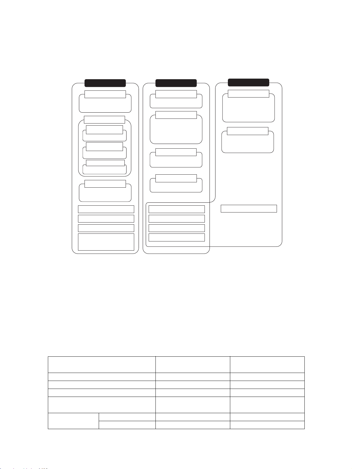
This manual describes the programming of the CPU Units for CS/CJ-series Programmable Controllers
(PLCs) and includes the sections described on the following page. The CS Series, CJ Series and NSJ
Series are subdivided as shown in the following figure.
CS Series
CS1-H CPU Units
CS1H-CPU@@H
CS1G-CPU@@H
CS1D CPU Units
CS1D CPU Units for
Duplex Systems
CS1D-CPU@@H
CS1D CPU Units for
Simplex Systems
CS1D-CPU@@S
CS1D Process-control CPU Units
CS1D-CPU@@P
CS1 CPU Units
CS1H-CPU@@(-V1)
CS1G-CPU@@(-V1)
CS-series Basic I/O Units
CS-series Special I/O Units
CS-series CPU Bus Units
CS-series Power Supply Units
Note: A special Power Supply Unit must
be used for CS1D CPU Units.
CJ Series
CJ2 CPU Units
CJ2H-CPU@@-@@@
CJ1-H CPU Units
CJ1H-CPU@@H-R
CJ1H-CPU@@H
CJ1G-CPU@@H
CJ1G -CPU@@P
(Loop-control CPU Units)
CJ1M CPU Units
CJ1M-CPU@@
CJ1 CPU Units
CJ1G-CPU@@
CJ-series Basic I/O Units
CJ-series Special I/O Units
CJ-series CPU Bus Units
CJ-series Power Supply Units
NSJ Series
NSJ Controllers
NSJ5-TQ@@(B)-G5D
NSJ5-SQ@@(B)-G5D
NSJ8-TV@@(B)-G5D
NSJ10-TV@@(B)-G5D
NSJ12-TS@@(B)-G5D
NSJ Controllers
NSJ5-TQ@@(B)-M3D
NSJ5-SQ@@(B)-M3D
NSJ8-TV@@(B)-M3D
NSJ-series Expansion Units
Please read this manual and all related manuals listed in the table on the next page and be sure you
understand information provided before attempting to install or use CS/CJ-series CPU Units in a PLC
System.
NSJ-series Controller Notation
For information in this manual on the Controller Section of NSJ-series Controllers, refer to the
information of the equivalent CJ-series PLC. The following models are equivalent.
NSJ-series Controllers Equivalent CJ-series CPU Unit
NSJ@-TQ@@(B)-G5D CJ1G-CPU45H with unit version 3.0
NSJ@-TQ@@(B)-M3D CJ1G-CPU45H with unit version 3.0 (See note.)
Note: The following points differ between the NSJ@-TQ@@(B)-M3D and the CJ1G-CPU45H.
Item CJ-series CPU Unit
CJ1G-CPU45H
I/O capacity 1280 points 640 points
Program capacity 60 Ksteps 20 Ksteps
No. of Expansion Racks 3 Racks max. 1 Rack max.
EM Area 32 Kwords × 3 banks
E0_00000 - E2_32767
Function blocks Max. No. of definitions 1024 128
Max. No. of instances 2048 256
Controller Section in
NSJ@-@@@@(B)-M3D
None
xxi
Page 22

Capacity in built-in
file memory
Item CJ-series CPU Unit
CJ1G-CPU45H
FB program memory 1024 KB 256 KB
Variable tables 128 KB 64 KB
Controller Section in
NSJ@-@@@@(B)-M3D
This manual contains the following sections.
Precautions provides general precautions for using the CS/CJ-series Programmable Controllers
(PLCs) and related devices.
Section 1 describes the basic structure and operation of the CPU Unit.
Section 2 describes basic information required to write, check, and input programs.
Section 3 outlines the instructions that can be used to write user programs.
Section 4 the operation of tasks.
Section 5 describes the functions used to manipulate file memory.
Section 6 provides details on the following advanced functions: cycle time/high-speed processing
functions, index register functions, serial communications functions, startup and maintenance functions, diagnostic and debugging functions, Programming Device functions, and the Basic I/O Unit input
response time settings.
Section 7 describes the processes used to transfer the program to the CPU Unit and the functions that
can be used to test and debug the program.
The Appendices provide a comparison of CS/CJ-series, restrictions in using C200H Special I/O Units,
and changes made to Host Link Systems.
xxii
Page 23

About this Manual, Continued
Name Cat. No. Contents
SYSMAC CS/CJ/NSJ Series
CS1G/H-CPU@@-EV1, CS1G/H-CPU@@H, CS1DCPU@@H, CS1D-CPU@@S, CJ1H-CPU@@H-R, CJ1GCPU@@, CJ1G/H-CPU@@H, CJ1G-CPU@@P, C J 1 M CPU@@, NSJ@-@@@@(B)-G5D, NSJ@-@@@@(B)-M3D
Programmable Controllers Programming Manual
SYSMAC CS Series
CS1G/H-CPU@@-EV1, CS1G/H-CPU@@H
Programmable Controllers Operation Manual
SYSMAC CJ Series
CJ1H-CPU@@H-R, CJ1G/H-CPU@@H, CJ1G-CPU@@P,
CJ1G-CPU@@, CJ1M-CPU@@
Programmable Controllers Operation Manual
SYSMAC CJ Series
CJ1M-CPU21/22/23
Built-in I/O Functions Operation Manual
SYSMAC CS Series
CS1D-CPU@@H CPU Units
CS1D-CPU@@S CPU Units
CS1D-DPL1 Duplex Unit
CS1D-PA207R Power Supply Unit
Duplex System Operation Manual
SYSMAC CS/CJ/NSJ Series
CS1G/H-CPU@@-EV1, CS1G/H-CPU@@H, CS1DCPU@@H, CS1D-CPU@@S, CJ1H-CPU@@H-R, CJ1GCPU@@, CJ1G/H-CPU@@H, CJ1G-CPU@@P, C J 1 M CPU@@, NSJ@-@@@@(B)-G5D, NSJ@-@@@@(B)-M3D
Programmable Controllers Instructions Reference Manual
SYSMAC CS/CJ Series
CQM1H-PRO01-E, C200H-PRO27-E, CQM1-PRO01-E
Programming Consoles Operation Manual
SYSMAC CS/CJ/NSJ Series
CS1G/H-CPU@@-EV1, CS1G/H-CPU@@H, CS1DCPU@@H, CS1D-CPU@@S, CJ1M-CPU@@, CJ1GCPU@@, CJ1G-CPU@@P, CJ1G/H-CPU@@H, CS1WSCB@@-V1, CS1W-SCU@@-V1, CJ1W-SCU@@-V1,
CP1H-X@@@@-@, CP1H-XA@@@@-@, CP1H-Y@@@@-@,
NSJ@-@@@@(B)-G5D, NSJ@-@@@@(B)-M3D
Communications Commands Reference Manual
NSJ Series
NSJ5-TQ@@(B)-G5D, NSJ5-SQ@@(B)-G5D, NSJ8-
TV@@(B)-G5D, NSJ10-TV@@(B)-G5D, NSJ12-TS@@(B)-
G5D
Operation Manual
W394
(This
manual)
W339 Provides an outlines of and describes the design,
W393 Provides an outlines of and describes the design,
W395 Describes the functions of the built-in I/O for
W405 Provides an outline of and describes the design,
W340 Describes the ladder diagram programming
W341 Provides information on how to program and
W342 Describes the C-series (Host Link) and FINS
W452 Provides the following information about the NSJ-
This manual describes programming and other
methods to use the functions of the CS/CJ/NSJseries PLCs.
installation, maintenance, and other basic operations for the CS-series PLCs.
installation, maintenance, and other basic operations for the CJ-series PLCs.
CJ1M CPU Units.
installation, maintenance, and other basic operations for a Duplex System based on CS1D CPU
Units.
instructions supported by CS/CJ-series PLCs.
operate CS/CJ-series PLCs using a Programming
Console.
communications commands used with CS/CJseries PLCs.
series NSJ Controllers:
Overview and features
Designing the system configuration
Installation and wiring
I/O memory allocations
Troubleshooting and maintenance
Use this manual in combination with the following
manuals: SYSMAC CS Series Operation Manual
(W339), SYSMAC CJ Series Operation Manual
(W393), SYSMAC CS/CJ Series Programming
Manual (W394), and NS-V1/-V2 Series Setup
Manual (V083)
xxiii
Page 24

Name Cat. No. Contents
SYSMAC WS02-CX@@-V@
CX-Programmer Operation Manual
SYSMAC WS02-CX@@-V@
CX-Programmer Operation Manual: Function Blocks
(CS1G-CPU
CJ1H-CPU@@H, CJ1M-CPU@@, CP1H-X@@@@-@,
CP1H-XA@@@@-@, and CP1H-Y@@@@-@ CPU Units)
SYSMAC CS/CJ Series
Programming Consoles Operation Manual
CQM1H-PRO01-E, CQM1-PRO01-E, C200H-PRO27-E
SYSMAC CS/CJ Series
CS1W-SCB
CJ1W-SCU
Serial Communications Boards/Units Operation Manual
SYSMAC WS02-PSTC1-E
CX-Protocol Operation Manual
CXONE-AL@@C-V3/AL@@D-V3
CX-Integrator Operation Manual
CXONE-AL@@C-V3/AL@@D-V3
CX-One Setup Manual
@@H, CS1H-CPU@@H, CJ1G-CPU@@H,
@@-V1, CS1W-SCU@@-V1,
@@-V1
W446 Provides information on how to use the CX-Pro-
grammer for all functionality except for function
blocks.
W447 Describes specifications and operation methods
related to function blocks. This information is
required only when using function blocks.
W341 Provides information on how to program and
operate CS/CJ-series PLCs using a Programming
Console.
When programming, use this manual together
with the Programmable Controllers Operation
Manual (W339 for CS-series PLCs and W393 for
CJ-series PLCs), CS/CJ-series Programmable
Controllers Programming Manual (W394,) and
the CS/CJ-series Programmable Controllers
Instructions Reference Manual (W340).
W336 Describes the use of Serial Communications Unit
and Boards to perform serial communications
with external devices, including the use of standard system protocols for OMRON products.
Refer to the CS/CJ Series Communications Commands Reference Manual (W342) for details on
sending commands in host link mode from a
Serial Communications Board or Unit’s port.
Refer to the WS02-PSTC1-E CX-Protocol Operation Manual (W344) for details on creating protocol macros.
W344 Describes the use of the CX-Protocol to create
protocol macros as communications sequences
to communicate with external devices.
W464 Describes operating procedures for the CX-Inte-
grator Network Configuration Tool for CS-, CJ-,
CP-, and NSJ-series Controllers.
W463 Installation and overview of CX-One FA Inte-
grated Tool Package.
!WARNING Failure to read and understand the information provided in this manual may result in per-
sonal injury or death, damage to the product, or product failure. Please read each section
in its entirety and be sure you understand the information provided in the section and
related sections before attempting any of the procedures or operations given.
xxiv
Page 25

PRECAUTIONS
This section provides general precautions for using the CS/CJ-series Programmable Controllers (PLCs) and related devices.
The information contained in this section is important for the safe and reliable application of Programmable
Controllers. You must read this section and understand the information contained before attempting to set up or
operate a PLC system.
1 Intended Audience . . . . . . . . . . . . . . . . . . . . . . . . . . . . . . . . . . . . . . . . . . . . . xxvi
2 General Precautions . . . . . . . . . . . . . . . . . . . . . . . . . . . . . . . . . . . . . . . . . . . . xxvi
3 Safety Precautions. . . . . . . . . . . . . . . . . . . . . . . . . . . . . . . . . . . . . . . . . . . . . . xxvi
4 Operating Environment Precautions . . . . . . . . . . . . . . . . . . . . . . . . . . . . . . . . xxviii
5 Application Precautions . . . . . . . . . . . . . . . . . . . . . . . . . . . . . . . . . . . . . . . . . xxviii
6 Conformance to EC Directives . . . . . . . . . . . . . . . . . . . . . . . . . . . . . . . . . . . . xxxii
6-1 Applicable Directives . . . . . . . . . . . . . . . . . . . . . . . . . . . . . . . . . . . . xxxii
6-2 Concepts . . . . . . . . . . . . . . . . . . . . . . . . . . . . . . . . . . . . . . . . . . . . . . xxxii
6-3 Conformance to EC Directives. . . . . . . . . . . . . . . . . . . . . . . . . . . . . xxxiii
6-4 Relay Output Noise Reduction Methods . . . . . . . . . . . . . . . . . . . . . xxxiii
xxv
Page 26

Intended Audience 1
1 Intended Audience
This manual is intended for the following personnel, who must also have
knowledge of electrical systems (an electrical engineer or the equivalent).
• Personnel in charge of installing FA systems.
• Personnel in charge of designing FA systems.
• Personnel in charge of managing FA systems and facilities.
2 General Precautions
The user must operate the product according to the performance specifications described in the operation manuals.
Before using the product under conditions which are not described in the
manual or applying the product to nuclear control systems, railroad systems,
aviation systems, vehicles, combustion systems, medical equipment, amusement machines, safety equipment, and other systems, machines, and equipment that may have a serious influence on lives and property if used
improperly, consult your OMRON representative.
Make sure that the ratings and performance characteristics of the product are
sufficient for the systems, machines, and equipment, and be sure to provide
the systems, machines, and equipment with double safety mechanisms.
This manual provides information for programming and operating the Unit. Be
sure to read this manual before attempting to use the Unit and keep this manual close at hand for reference during operation.
!WARNING It is extremely important that a PLC and all PLC Units be used for the speci-
fied purpose and under the specified conditions, especially in applications that
can directly or indirectly affect human life. You must consult with your OMRON
representative before applying a PLC System to the above-mentioned applications.
3 Safety Precautions
!WARNING The CPU Unit refreshes I/O even when the program is stopped (i.e., even in
PROGRAM mode). Confirm safety thoroughly in advance before changing the
status of any part of memory allocated to I/O Units, Special I/O Units, or CPU
Bus Units. Any changes to the data allocated to any Unit may result in unexpected operation of the loads connected to the Unit. Any of the following operation may result in changes to memory status.
• Transferring I/O memory data to the CPU Unit from a Programming
Device.
• Changing present values in memory from a Programming Device.
• Force-setting/-resetting bits from a Programming Device.
• Transferring I/O memory files from a Memory Card or EM file memory to
the CPU Unit.
• Transferring I/O memory from a host computer or from another PLC on a
network.
xxvi
!WARNING Do not attempt to take any Unit apart while the power is being supplied. Doing
so may result in electric shock.
Page 27

Safety Precautions 3
!WARNING Do not touch any of the terminals or terminal blocks while the power is being
supplied. Doing so may result in electric shock.
!WARNING Do not attempt to disassemble, repair, or modify any Units. Any attempt to do
so may result in malfunction, fire, or electric shock.
!WARNING Provide safety measures in external circuits (i.e., not in the Programmable
Controller), including the following items, to ensure safety in the system if an
abnormality occurs due to malfunction of the PLC or another external factor
affecting the PLC operation. Not doing so may result in serious accidents.
• Emergency stop circuits, interlock circuits, limit circuits, and similar safety
measures must be provided in external control circuits.
• The PLC will turn OFF all outputs when its self-diagnosis function detects
any error or when a severe failure alarm (FALS) instruction is executed.
As a countermeasure for such errors, external safety measures must be
provided to ensure safety in the system.
• The PLC outputs may remain ON or OFF due to deposition or burning of
the output relays or destruction of the output transistors. As a countermeasure for such problems, external safety measures must be provided
to ensure safety in the system.
• When the 24-V DC output (service power supply to the PLC) is overloaded or short-circuited, the voltage may drop and result in the outputs
being turned OFF. As a countermeasure for such problems, external
safety measures must be provided to ensure safety in the system.
!Caution Confirm safety before transferring data files stored in the file memory (Mem-
ory Card or EM file memory) to the I/O area (CIO) of the CPU Unit using a
peripheral tool. Otherwise, the devices connected to the output unit may malfunction regardless of the operation mode of the CPU Unit.
!Caution Fail-safe measures must be taken by the customer to ensure safety in the
event of incorrect, missing, or abnormal signals caused by broken signal lines,
momentary power interruptions, or other causes. Abnormal operation may
result in serious accidents.
!Caution The CS1-H, CJ1-H, CJ1M, and CS1D CPU Units automatically back up the
user program and parameter data to flash memory when these are written to
the CPU Unit. I/O memory (including the DM, EM, and HR Areas), however, is
not written to flash memory. The DM, EM, and HR Areas can be held during
power interruptions with a battery. If there is a battery error, the contents of
these areas may not be accurate after a power interruption. If the contents of
the DM, EM, and HR Areas are used to control external outputs, prevent inappropriate outputs from being made whenever the Battery Error Flag (A40204)
is ON.
!Caution Execute online edit only after confirming that no adverse effects will be
caused by extending the cycle time. Otherwise, the input signals may not be
readable.
!Caution Confirm safety at the destination node before transferring a program to
another node or changing contents of the I/O memory area. Doing either of
these without confirming safety may result in injury.
xxvii
Page 28

Operating Environment Precautions 4
!Caution Tighten the screws on the terminal block of the AC Power Supply Unit to the
torque specified in the operation manual. The loose screws may result in
burning or malfunction.
!Caution Do not touch the Power Supply Unit when power is being supplied or immedi-
ately after the power supply is turned OFF. The Power Supply Unit will be hot
and you may be burned.
!Caution Be careful when connecting personal computers or other peripheral devices
to a PLC to which is mounted a non-insulated Unit (CS1W-CLK12/52(-V1) or
CS1W-ETN01) connected to an external power supply. A short-circuit will be
created if the 24 V side of the external power supply is grounded and the 0 V
side of the peripheral device is grounded. When connecting a peripheral
device to this type of PLC, either ground the 0 V side of the external power
supply or do not ground the external power supply at all.
4 Operating Environment Precautions
!Caution Do not operate the control system in the following locations:
• Locations subject to direct sunlight.
• Locations subject to temperatures or humidity outside the range specified
in the specifications.
• Locations subject to condensation as the result of severe changes in temperature.
• Locations subject to corrosive or flammable gases.
• Locations subject to dust (especially iron dust) or salts.
• Locations subject to exposure to water, oil, or chemicals.
• Locations subject to shock or vibration.
!Caution Take appropriate and sufficient countermeasures when installing systems in
the following locations:
• Locations subject to static electricity or other forms of noise.
• Locations subject to strong electromagnetic fields.
• Locations subject to possible exposure to radioactivity.
• Locations close to power supplies.
!Caution The operating environment of the PLC System can have a large effect on the
longevity and reliability of the system. Improper operating environments can
lead to malfunction, failure, and other unforeseeable problems with the PLC
System. Be sure that the operating environment is within the specified conditions at installation and remains within the specified conditions during the life
of the system.
5 Application Precautions
Observe the following precautions when using the PLC System.
• You must use the CX-Programmer (programming software that runs on
Windows) if you need to program more than one task. A Programming
Console can be used to program only one cyclic task plus interrupt tasks.
xxviii
Page 29

Application Precautions 5
A Programming Console can, however, be used to edit multitask programs originally created with the CX-Programmer.
!WARNING Always heed these precautions. Failure to abide by the following precautions
could lead to serious or possibly fatal injury.
• Always connect to a ground of 100
connecting to a ground of 100
• A ground of 100 Ω or less must be installed when shorting the GR and LG
terminals on the Power Supply Unit.
• Always turn OFF the power supply to the PLC before attempting any of
the following. Not turning OFF the power supply may result in malfunction
or electric shock.
• Mounting or dismounting Power Supply Units, I/O Units, CPU Units, Inner Boards, or any other Units.
• Assembling the Units.
• Setting DIP switches or rotary switches.
• Connecting cables or wiring the system.
• Connecting or disconnecting the connectors.
!Caution Failure to abide by the following precautions could lead to faulty operation of
the PLC or the system, or could damage the PLC or PLC Units. Always heed
these precautions.
• The user program and parameter area data in the CS1-H, CS1D, CJ1-H,
and CJ1M CPU Units are backed up in the built-in flash memory. The
BKUP indicator will light on the front of the CPU Unit when the backup
operation is in progress. Do not turn OFF the power supply to the CPU
Unit when the BKUP indicator is lit. The data will not be backed up if
power is turned OFF.
• When using a CS-series CS1 CPU Unit for the first time, install the
CS1W-BAT1 Battery provided with the Unit and clear all memory areas
from a Programming Device before starting to program. When using the
internal clock, turn ON power after installing the battery and set the clock
from a Programming Device or using the DATE(735) instruction. The clock
will not start until the time has been set.
• When the CPU Unit is shipped from the factory, the PLC Setup is set so
that the CPU Unit will start in the operating mode set on the Programming
Console mode switch. When a Programming Console is not connected, a
CS-series CS1 CPU Unit will start in PROGRAM mode, but a CS1-H,
CS1D, CJ1, CJ1-H, or CJ1M CPU Unit will start in RUN mode and operation will begin immediately. Do not advertently or inadvertently allow operation to start without confirming that it is safe.
• When creating an AUTOEXEC.IOM file from a Programming Device (a
Programming Console or the CX-Programmer) to automatically transfer
data at startup, set the first write address to D20000 and be sure that the
size of data written does not exceed the size of the DM Area. When the
data file is read from the Memory Card at startup, data will be written in
the CPU Unit starting at D20000 even if another address was set when
the AUTOEXEC.IOM file was created. Also, if the DM Area is exceeded
(which is possible when the CX-Programmer is used), the remaining data
will be written to the EM Area.
Ω or less when installing the Units. Not
Ω or less may result in electric shock.
xxix
Page 30

Application Precautions 5
• Always turn ON power to the PLC before turning ON power to the control
system. If the PLC power supply is turned ON after the control power supply, temporary errors may result in control system signals because the
output terminals on DC Output Units and other Units will momentarily turn
ON when power is turned ON to the PLC.
• Fail-safe measures must be taken by the customer to ensure safety in the
event that outputs from Output Units remain ON as a result of internal circuit failures, which can occur in relays, transistors, and other elements.
• Fail-safe measures must be taken by the customer to ensure safety in the
event of incorrect, missing, or abnormal signals caused by broken signal
lines, momentary power interruptions, or other causes.
• Interlock circuits, limit circuits, and similar safety measures in external circuits (i.e., not in the Programmable Controller) must be provided by the
customer.
• Do not turn OFF the power supply to the PLC when data is being transferred. In particular, do not turn OFF the power supply when reading or
writing a Memory Card. Also, do not remove the Memory Card when the
BUSY indicator is lit. To remove a Memory Card, first press the memory
card power supply switch and then wait for the BUSY indicator to go out
before removing the Memory Card.
• If the I/O Hold Bit is turned ON, the outputs from the PLC will not be
turned OFF and will maintain their previous status when the PLC is
switched from RUN or MONITOR mode to PROGRAM mode. Make sure
that the external loads will not produce dangerous conditions when this
occurs. (When operation stops for a fatal error, including those produced
with the FALS(007) instruction, all outputs from Output Unit will be turned
OFF and only the internal output status will be maintained.)
• The contents of the DM, EM, and HR Areas in the CPU Unit are backed
up by a Battery. If the Battery voltage drops, this data may be lost. Provide
countermeasures in the program using the Battery Error Flag (A40204) to
re-initialize data or take other actions if the Battery voltage drops.
• When supplying power at 200 to 240 V AC with a CS-series PLC, always
remove the metal jumper from the voltage selector terminals on the Power
Supply Unit (except for Power Supply Units with wide-range specifications). The product will be destroyed if 200 to 240 V AC is supplied while
the metal jumper is attached.
• Always use the power supply voltages specified in the operation manuals.
An incorrect voltage may result in malfunction or burning.
• Take appropriate measures to ensure that the specified power with the
rated voltage and frequency is supplied. Be particularly careful in places
where the power supply is unstable. An incorrect power supply may result
in malfunction.
• Install external breakers and take other safety measures against short-circuiting in external wiring. Insufficient safety measures against short-circuiting may result in burning.
• Do not apply voltages to the Input Units in excess of the rated input voltage. Excess voltages may result in burning.
• Do not apply voltages or connect loads to the Output Units in excess of
the maximum switching capacity. Excess voltage or loads may result in
burning.
xxx
Page 31

Application Precautions 5
• Separate the line ground terminal (LG) from the functional ground terminal (GR) on the Power Supply Unit before performing withstand voltage
tests or insulation resistance tests. Not doing so may result in burning.
• Install the Units properly as specified in the operation manuals. Improper
installation of the Units may result in malfunction.
• With CS-series PLCs, be sure that all the Unit and Backplane mounting
screws are tightened to the torque specified in the relevant manuals.
Incorrect tightening torque may result in malfunction.
• Be sure that all terminal screws, and cable connector screws are tightened to the torque specified in the relevant manuals. Incorrect tightening
torque may result in malfunction.
• Leave the label attached to the Unit when wiring. Removing the label may
result in malfunction if foreign matter enters the Unit.
• Remove the label after the completion of wiring to ensure proper heat dissipation. Leaving the label attached may result in malfunction.
• Use crimp terminals for wiring. Do not connect bare stranded wires
directly to terminals. Connection of bare stranded wires may result in
burning.
• Wire all connections correctly.
• Double-check all wiring and switch settings before turning ON the power
supply. Incorrect wiring may result in burning.
• Mount Units only after checking terminal blocks and connectors completely.
• Be sure that the terminal blocks, Memory Units, expansion cables, and
other items with locking devices are properly locked into place. Improper
locking may result in malfunction.
• Check switch settings, the contents of the DM Area, and other preparations before starting operation. Starting operation without the proper settings or data may result in an unexpected operation.
• Check the user program for proper execution before actually running it on
the Unit. Not checking the program may result in an unexpected operation.
• Confirm that no adverse effect will occur in the system before attempting
any of the following. Not doing so may result in an unexpected operation.
• Changing the operating mode of the PLC (including the setting of the
startup operating mode).
• Force-setting/force-resetting any bit in memory.
• Changing the present value of any word or any set value in memory.
• Do not pull on the cables or bend the cables beyond their natural limit.
Doing either of these may break the cables.
• Do not place objects on top of the cables or other wiring lines. Doing so
may break the cables.
• Do not use commercially available RS-232C personal computer cables.
Always use the special cables listed in this manual or make cables
according to manual specifications. Using commercially available cables
may damage the external devices or CPU Unit.
• Never connect pin 6 (5-V power supply) on the RS-232C port on the CPU
Unit to any device other than an NT-AL001 or CJ1W-CIF11 Adapter. The
external device or the CPU Unit may be damaged.
xxxi
Page 32

Conformance to EC Directives 6
• When replacing parts, be sure to confirm that the rating of a new part is
correct. Not doing so may result in malfunction or burning.
• Before touching a Unit, be sure to first touch a grounded metallic object in
order to discharge any static build-up. Not doing so may result in malfunction or damage.
• When transporting or storing circuit boards, cover them in antistatic material to protect them from static electricity and maintain the proper storage
temperature.
• Do not touch circuit boards or the components mounted to them with your
bare hands. There are sharp leads and other parts on the boards that
may cause injury if handled improperly.
• Do not short the battery terminals or charge, disassemble, heat, or incinerate the battery. Do not subject the battery to strong shocks. Doing any
of these may result in leakage, rupture, heat generation, or ignition of the
battery. Dispose of any battery that has been dropped on the floor or otherwise subjected to excessive shock. Batteries that have been subjected
to shock may leak if they are used.
• UL standards required that batteries be replaced only by experienced
technicians. Do not allow unqualified persons to replace batteries.
• Dispose of the product and batteries according to local ordinances as they apply. Have qualified specialists properly
dispose of used batteries as industrial waste.
• With a CJ-series PLC, the sliders on the tops and bottoms
of the Power Supply Unit, CPU Unit, I/O Units, Special I/O Units, and CPU
Bus Units must be completely locked (until they click into place). The Unit
may not operate properly if the sliders are not locked in place.
• With a CJ-series PLC, always connect the End Plate to the Unit on the
right end of the PLC. The PLC will not operate properly without the End
Plate
• Unexpected operation may result if inappropriate data link tables or
parameters are set. Even if appropriate data link tables and parameters
have been set, confirm that the controlled system will not be adversely
affected before starting or stopping data links.
• CPU Bus Units will be restarted when routing tables are transferred from
a Programming Device to the CPU Unit. Restarting these Units is required
to read and enable the new routing tables. Confirm that the system will
not be adversely affected before allowing the CPU Bus Units to be reset.
6 Conformance to EC Directives
6-1 Applicable Directives
•EMC Directives
• Low Voltage Directive
6-2 Concepts
xxxii
EMC Directives
OMRON devices that comply with EC Directives also conform to the related
EMC standards so that they can be more easily built into other devices or the
overall machine. The actual products have been checked for conformity to
EMC standards (see the following note). Whether the products conform to the
Page 33

Conformance to EC Directives 6
standards in the system used by the customer, however, must be checked by
the customer.
EMC-related performance of the OMRON devices that comply with EC Directives will vary depending on the configuration, wiring, and other conditions of
the equipment or control panel on which the OMRON devices are installed.
The customer must, therefore, perform the final check to confirm that devices
and the overall machine conform to EMC standards.
Note Applicable EMC (Electromagnetic Compatibility) standards are as follows:
EMS (Electromagnetic Susceptibility):
CS Series: EN61131-2 and EN61000-6-2
CJ Series: EN61000-6-2
EMI (Electromagnetic Interference):
EN61000-6-4
(Radiated emission: 10-m regulations)
Low Voltage Directive
Always ensure that devices operating at voltages of 50 to 1,000 V AC and 75
to 1,500 V DC meet the required safety standards for the PLC (EN61131-2).
6-3 Conformance to EC Directives
The CS/CJ-series PLCs comply with EC Directives. To ensure that the
machine or device in which the CS/CJ-series PLC is used complies with EC
Directives, the PLC must be installed as follows:
1,2,3... 1. The CS/CJ-series PLC must be installed within a control panel.
2. You must use reinforced insulation or double insulation for the DC power
supplies connected to DC Power Supply Units and I/O Units.
3. CS/CJ-series PLCs complying with EC Directives also conform to the
Common Emission Standard (EN61000-6-4). Radiated emission characteristics (10-m regulations) may vary depending on the configuration of the
control panel used, other devices connected to the control panel, wiring,
and other conditions. You must therefore confirm that the overall machine
or equipment complies with EC Directives.
6-4 Relay Output Noise Reduction Methods
The CS/CJ-series PLCs conforms to the Common Emission Standards
(EN61000-6-4) of the EMC Directives. However, noise generated by relay output switching may not satisfy these Standards. In such a case, a noise filter
must be connected to the load side or other appropriate countermeasures
must be provided external to the PLC.
Countermeasures taken to satisfy the standards vary depending on the
devices on the load side, wiring, configuration of machines, etc. Following are
examples of countermeasures for reducing the generated noise.
Countermeasures
(Refer to EN61000-6-4 for more details.)
Countermeasures are not required if the frequency of load switching for the
whole system with the PLC included is less than 5 times per minute.
Countermeasures are required if the frequency of load switching for the whole
system with the PLC included is more than 5 times per minute.
xxxiii
Page 34

Conformance to EC Directives 6
Countermeasure Examples
When switching an inductive load, connect an surge protector, diodes, etc., in
parallel with the load or contact as shown below.
Circuit Current Characteristic Required element
AC DC
CR method
C
Power
supply
R
Diode method
Power
supply
Varistor method
Power
supply
Yes Yes If the load is a relay or solenoid, there is
a time lag between the moment the circuit is opened and the moment the load
is reset.
If the supply voltage is 24 or 48 V, insert
Inductive
load
the surge protector in parallel with the
load. If the supply voltage is 100 to
200 V, insert the surge protector
between the contacts.
No Yes The diode connected in parallel with
the load changes energy accumulated
by the coil into a current, which then
flows into the coil so that the current will
be converted into Joule heat by the
Inductive
load
resistance of the inductive load.
This time lag, between the moment the
circuit is opened and the moment the
load is reset, caused by this method is
longer than that caused by the CR
method.
Yes Yes The varistor method prevents the impo-
sition of high voltage between the contacts by using the constant voltage
characteristic of the varistor. There is
time lag between the moment the cir-
Inductive
load
cuit is opened and the moment the load
is reset.
If the supply voltage is 24 or 48 V, insert
the varistor in parallel with the load. If
the supply voltage is 100 to 200 V,
insert the varistor between the contacts.
The capacitance of the capacitor must
be 1 to 0.5 µF per contact current of
1 A and resistance of the resistor must
be 0.5 to 1 Ω per contact voltage of 1 V.
These values, however, vary with the
load and the characteristics of the
relay. Decide these values from experiments, and take into consideration that
the capacitance suppresses spark discharge when the contacts are separated and the resistance limits the
current that flows into the load when
the circuit is closed again.
The dielectric strength of the capacitor
must be 200 to 300 V. If the circuit is an
AC circuit, use a capacitor with no
polarity.
The reversed dielectric strength value
of the diode must be at least 10 times
as large as the circuit voltage value.
The forward current of the diode must
be the same as or larger than the load
current.
The reversed dielectric strength value
of the diode may be two to three times
larger than the supply voltage if the
surge protector is applied to electronic
circuits with low circuit voltages.
---
xxxiv
When switching a load with a high inrush current such as an incandescent
lamp, suppress the inrush current as shown below.
Countermeasure 1 Countermeasure 2
OUT
R
COM
Providing a dark current of
approx. one-third of the rated
value through an
incandescent lamp
OUT
COM
Providing a limiting resistor
R
Page 35

Read and Understand this Manual
Please read and understand this manual before using the product. Please consult your OMRON
representative if you have any questions or comments.
Warranty and Limitations of Liability
WARRANTY
OMRON's exclusive warranty is that the products are free from defects in materials and workmanship for a
period of one year (or other period if specified) from date of sale by OMRON.
OMRON MAKES NO WARRANTY OR REPRESENTATION, EXPRESS OR IMPLIED, REGARDING NONINFRINGEMENT, MERCHANTABILITY, OR FITNESS FOR PARTICULAR PURPOSE OF THE
PRODUCTS. ANY BUYER OR USER ACKNOWLEDGES THAT THE BUYER OR USER ALONE HAS
DETERMINED THAT THE PRODUCTS WILL SUITABLY MEET THE REQUIREMENTS OF THEIR
INTENDED USE. OMRON DISCLAIMS ALL OTHER WARRANTIES, EXPRESS OR IMPLIED.
LIMITATIONS OF LIABILITY
OMRON SHALL NOT BE RESPONSIBLE FOR SPECIAL, INDIRECT, OR CONSEQUENTIAL DAMAGES,
LOSS OF PROFITS OR COMMERCIAL LOSS IN ANY WAY CONNECTED WITH THE PRODUCTS,
WHETHER SUCH CLAIM IS BASED ON CONTRACT, WARRANTY, NEGLIGENCE, OR STRICT
LIABILITY.
In no event shall the responsibility of OMRON for any act exceed the individual price of the product on which
liability is asserted.
IN NO EVENT SHALL OMRON BE RESPONSIBLE FOR WARRANTY, REPAIR, OR OTHER CLAIMS
REGARDING THE PRODUCTS UNLESS OMRON'S ANALYSIS CONFIRMS THAT THE PRODUCTS
WERE PROPERLY HANDLED, STORED, INSTALLED, AND MAINTAINED AND NOT SUBJECT TO
CONTAMINATION, ABUSE, MISUSE, OR INAPPROPRIATE MODIFICATION OR REPAIR.
xxxv
Page 36

Application Considerations
SUITABILITY FOR USE
OMRON shall not be responsible for conformity with any standards, codes, or regulations that apply to the
combination of products in the customer's application or use of the products.
At the customer's request, OMRON will provide applicable third party certification documents identifying
ratings and limitations of use that apply to the products. This information by itself is not sufficient for a
complete determination of the suitability of the products in combination with the end product, machine,
system, or other application or use.
The following are some examples of applications for which particular attention must be given. This is not
intended to be an exhaustive list of all possible uses of the products, nor is it intended to imply that the uses
listed may be suitable for the products:
• Outdoor use, uses involving potential chemical contamination or electrical interference, or conditions or
uses not described in this manual.
• Nuclear energy control systems, combustion systems, railroad systems, aviation systems, medical
equipment, amusement machines, vehicles, safety equipment, and installations subject to separate
industry or government regulations.
• Systems, machines, and equipment that could present a risk to life or property.
Please know and observe all prohibitions of use applicable to the products.
NEVER USE THE PRODUCTS FOR AN APPLICATION INVOLVING SERIOUS RISK TO LIFE OR
PROPERTY WITHOUT ENSURING THAT THE SYSTEM AS A WHOLE HAS BEEN DESIGNED TO
ADDRESS THE RISKS, AND THAT THE OMRON PRODUCTS ARE PROPERLY RATED AND INSTALLED
FOR THE INTENDED USE WITHIN THE OVERALL EQUIPMENT OR SYSTEM.
PROGRAMMABLE PRODUCTS
OMRON shall not be responsible for the user's programming of a programmable product, or any
consequence thereof.
xxxvi
Page 37

Disclaimers
CHANGE IN SPECIFICATIONS
Product specifications and accessories may be changed at any time based on improvements and other
reasons.
It is our practice to change model numbers when published ratings or features are changed, or when
significant construction changes are made. However, some specifications of the products may be changed
without any notice. When in doubt, special model numbers may be assigned to fix or establish key
specifications for your application on your request. Please consult with your OMRON representative at any
time to confirm actual specifications of purchased products.
DIMENSIONS AND WEIGHTS
Dimensions and weights are nominal and are not to be used for manufacturing purposes, even when
tolerances are shown.
PERFORMANCE DATA
Performance data given in this manual is provided as a guide for the user in determining suitability and does
not constitute a warranty. It may represent the result of OMRON's test conditions, and the users must
correlate it to actual application requirements. Actual performance is subject to the OMRON Warranty and
Limitations of Liability.
ERRORS AND OMISSIONS
The information in this manual has been carefully checked and is believed to be accurate; however, no
responsibility is assumed for clerical, typographical, or proofreading errors, or omissions.
xxxvii
Page 38

xxxviii
Page 39

CPU Unit Operation
This section describes the basic structure and operation of the CPU Unit.
1-1 Initial Setup (CS1 CPU Units Only) . . . . . . . . . . . . . . . . . . . . . . . . . . . . . . . . 2
1-2 Using the Internal Clock (CS1 CPU Units Only) . . . . . . . . . . . . . . . . . . . . . . 5
1-3 Internal Structure of the CPU Unit . . . . . . . . . . . . . . . . . . . . . . . . . . . . . . . . . 6
1-3-1 Overview. . . . . . . . . . . . . . . . . . . . . . . . . . . . . . . . . . . . . . . . . . . . . . 6
1-3-2 Block Diagram of CPU Unit Memory . . . . . . . . . . . . . . . . . . . . . . . 7
1-4 Operating Modes. . . . . . . . . . . . . . . . . . . . . . . . . . . . . . . . . . . . . . . . . . . . . . . 9
1-4-1 Description of Operating Modes . . . . . . . . . . . . . . . . . . . . . . . . . . . 9
1-4-2 Initialization of I/O Memory . . . . . . . . . . . . . . . . . . . . . . . . . . . . . . 10
1-4-3 Startup Mode . . . . . . . . . . . . . . . . . . . . . . . . . . . . . . . . . . . . . . . . . . 11
1-5 Programs and Tasks. . . . . . . . . . . . . . . . . . . . . . . . . . . . . . . . . . . . . . . . . . . . . 13
1-6 Description of Tasks . . . . . . . . . . . . . . . . . . . . . . . . . . . . . . . . . . . . . . . . . . . . 15
SECTION 1
1
Page 40

Initial Setup (CS1 CPU Units Only) Section 1-1
1-1 Initial Setup (CS1 CPU Units Only)
Battery Installation Before using a CS1CPU Unit, you must install the Battery Set in the CPU Unit
using the following procedure.
1,2,3... 1. Insert a flat-blade screwdriver in the small gap at the bottom of the battery
compartment and flip the cover upward to open it.
2
Page 41

Initial Setup (CS1 CPU Units Only) Section 1-1
2. Hold the Battery Set with the cable facing outward and insert it into the battery compartment.
Battery compartment
3. Connect the battery connector to the battery connector terminals. Connect
the red wire to the top and the white wire to the bottom terminal. There are
two sets of battery connector terminals; connect the battery to either one.
It does not matter whether the top terminals or bottom terminals are used.
Red
Battery connector terminals
(Connect to either set of terminals.)
White
3
Page 42

Initial Setup (CS1 CPU Units Only) Section 1-1
4. Fold in the cable and close the cover.
Clearing Memory After installing the battery, clear memory using the memory clear operation to
initialize the RAM inside the CPU Unit.
Programming Console
Use the following procedure from a Programming Console.
Initial display
NOT
SET RESET
MON
(or
0
0
1
MON
)
Note You cannot specify more than one cyclic task when clearing memory from a
Programming Console. You can specify one cyclic task and one interrupt task,
or one cyclic task and no interrupt task. Refer to the Operation Manual for
more information on the memory clear operation. Refer to
Unit Operation
and SECTION 4 Tasks for more information on tasks.
SECTION 1 CPU
CX-Programmer
Memory can also be cleared from the CX-Programmer. Refer to the CX-Programmer Operation Manual for the actual procedure.
Clearing Errors After clearing memory, clear any errors from the CPU Unit, including the low
battery voltage error.
Programming Console
Use the following procedure from a Programming Console.
Initial display
MONFUN MON
(Displayed error will be cleared.)
MON
(Returns to the initial display.)
CX-Programmer
Errors can also be cleared from the CX-Programmer. Refer to the CX-Programmer Operation Manual for the actual procedure.
Note When an Inner Board is mounted, an Inner Board routing table error may con-
tinue even after you have cancelled the error using the CX-Programmer.
(A42407 will be ON for a Serial Communications Board.) If this occurs, either
reset the power or restart the Inner Board, then cancel the error again.
4
Page 43

Using the Internal Clock (CS1 CPU Units Only) Section 1-2
1-2 Using the Internal Clock (CS1 CPU Units Only)
The internal clock of the CPU Unit is set to “00 year, 01 month, 01 day (00-01-
01), 00 hours, 00 minutes, 00 seconds (00:00:00), and Sunday (SUN)” when
the Battery Set is mounted in the CS-series CPU Unit.
When using the internal clock, turn ON the power supply after mounting the
Battery Set and 1) use a Programming Device (Programming Console or CXProgrammer) to set the clock time, 2) execute the CLOCK ADJUSTMENT
(DATE) instruction, or 3) send a FINS command to start the internal clock from
the correct current time and date.
The Programming Console operation used to set the internal clock is shown
below.
Key Sequence
Initial display
FUN
SHIFT
MON
0
CHG
↑
Data
WRITE
↓
Specify: Yr Mo Day Hr Min S
5
Page 44

Internal Structure of the CPU Unit Section 1-3
1-3 Internal Structure of the CPU Unit
1-3-1 Overview
The following diagram shows the internal structure of the CPU Unit.
CPU Unit
User program
Automatic
backup
Flash
memory
(CS1-H, CS1D, CJ1-H,
or CJ1M CPU Units only)
EM file memory
Automatic
backup
I/O memory
PLC Setup
and other
parameters
Access
Task 1
Task 2
Task n
Memory Card
DIP switch
The program is divided
into tasks and the tasks
are executed in order by
task number.
I/O memory, PC Setup,
programs and the EM area
can be saved as files.
The User Program The user program is created from up to 288 program tasks, including interrupt
tasks. The tasks are transferred to the CPU Unit from the CX-Programmer
programming software.
There are two types of tasks. The first is a cyclic task that is executed once
per cycle (maximum of 32) and the other is an interrupt task that is executed
only when the interrupt conditions occur (maximum of 256). Cyclic tasks are
executed in numerical order.
Interrupt tasks can also be executed cyclically, like cyclic tasks. In this case,
the total number of tasks that can be executed cyclically is 288.
Note The CS1G/H-CPU@@(-V1) and CJ1@-CPU@@ CPU Units are not equipped
with a function to execute interrupt tasks like cyclic tasks.
Program instructions read and write to I/O memory and are executed in order
starting at the top of the program. After all cyclic tasks are executed, the I/O
for all Units are refreshed, and the cycle repeats again starting at the lowest
cyclic task number.
Refer to the section on CPU Unit operation in the CS/CJ Series Operation
Manual for details on refreshing I/O.
I/O Memory I/O memory is the RAM area used for reading and writing from the user pro-
gram. It is comprised of one area that is cleared when power is turned ON and
OFF, and another area that will retain data.
I/O memory is also partitioned into an area that exchanges data with all Units
and an area strictly for internal use. Data is exchanged with all Units once per
program execution cycle and also when specific instructions are executed.
6
Page 45

Internal Structure of the CPU Unit Section 1-3
PLC Setup The PLC Setup is used to set various initial or other settings through software
switches.
DIP Switches DIP switches are used to set initial or other settings through hardware
switches.
Memory Cards Memory Cards are used as needed to store data such as programs, I/O mem-
ory data, the PLC Setup, and I/O comments created by Programming
Devices. Programs and various system settings can be written automatically
from the Memory Card when power is turned ON (automatic transfer at startup).
Flash Memory The user program and parameter area data, such as the PLC Setup, are auto-
matically backed up in the built-in flash memory whenever the user writes
data to the CPU Unit. This enables battery-free operation without using a
Memory Card. I/O memory, including most of the DM Area, are not backed up
without a battery.
Note The CS1G/H-CPU@@(-V1) and CJ1@-CPU@@ CPU Units are not equipped
with the flash memory functions and the data is backed up by the battery.
Consequently, the data is not backed up when a battery is not installed.
1-3-2 Block Diagram of CPU Unit Memory
CPU Unit memory (RAM) is comprised of the following blocks in the CS/CJ
Series:
Area name Contents Backup method Status when battery
User Program
Area
Parameter
Area
I/O Memory
Areas
Comment
Memory Area
Source Memory Area
User program Internal flash
PLC Setup, Registered I/O Tables,
Routing Tables, and
CPU Bus Unit settings
Data areas such as
the HR, DM, and EM
Areas
Comment information Internal flash mem-
Function block
information
memory
Battery and internal
flash memory
Battery Data is not lost.
ory
Internal flash mem-
ory
voltage drops
Data is not lost.
Data is not lost when
the PLC Setup's
Detect Low Battery
setting is set to Do
not detect.
Data is not lost.
Data is not lost.
User Program Area
The CPU Unit backs up this data in internal flash memory. The user program
is automatically backed up in flash memory if it was overwritten by a program
transfer from the CX-Programmer, online editing, or a transfer from the Memory Card. Even if the battery voltage drops, the user program data will not be
lost.
Note The CS1G/H-CPU@@(-V1) and CJ1@-CPU@@ CPU Units are not equipped
with the flash memory functions and the data is backed up by the battery.
Consequently, the data is not backed up when a battery is not installed.
Parameter Area (PLC Setup, Registered I/O Tables, Routing Tables, and
CPU Bus Unit Settings)
If the PLC Setup's Detect Low Battery setting is set to Do not detect, this data
is backed up in the internal flash memory. The data is automatically backed up
in flash memory if the parameters are overwritten by an operation such as a
7
Page 46

Internal Structure of the CPU Unit Section 1-3
transfer from the CX-Programmer or a transfer from the Memory Card. If the
PLC Setup's Detect Low Battery setting is set to Do not detect, the Parameter
Area data will not be lost even if the battery voltage drops.
Note The CS1G/H-CPU@@(-V1) and CJ1@-CPU@@ CPU Units are not equipped
with the flash memory functions and the data is backed up by the battery.
Consequently, the data is not backed up when battery is not installed.
I/O Memory Areas
This data is backed up by the battery (CS1W-BAT01 in CS-series PLCs,
CPM2A-BAT01 in CJ1H PLCs, or CJ1W-BAT01 in CJ1M PLCs). If the battery
voltage drops, this data will be lost.
Comment Memory Area and Source Memory Area
The CPU Unit backs up this data in its internal flash memory. When a comment file or function block used in the program is transferred from the CX-Programmer, it is stored in flash memory. Even if the battery voltage drops, the
data will not be lost.
Only CPU Units with unit version 3.0 or later are equipped with this memory.
CPU Unit
Built-in RAM
I/O memory area
Flash Memory
(CS1-H, CJ1-H, CJ1M, or
CS1D CPU Units only)
User program
Parameter area
Comment memory
area
FB program memory
area
Drive 1: EM file memory
(See note 2.)
Automatic
write
Automatic
write
User program
Parameter area
(See note 1.)
Backup
Battery
A newly mounted battery will be good up to
five years at an ambient temperature of 25°C
Drive 0: Memory Card
(flash memory)
File memory
Automatically backed up to flash memory whenever a write
operation for the user memory area (user program or parameter
area) is performed from a Programming Device.
Used to store symbol table files, comment files, and program
index files. CPU Units with unit version 3.0 or later, Memory
Card, EM file memory, or comment memory can be selected as
the destination when transferring projects from CX-Programmer
Ver. 5.0.
When transferring projects containing function blocks from the
CX-Programmer for CPU Units with unit version 3.0 or later,
the function block program information is automatically stored
in the FB program memory area.
Note 1. The BKUP indicator on the front of the CPU Unit will light while data is be-
ing written to flash memory. Do not turn OFF the power supply to the CPU
Unit until the backup operation has been completed (i.e., until the BKUP
indicator goes out). Refer to
6-6-11 Flash Memory for details.
2. A Battery is mounted to a CS1-H, CJ1, CJ1-H, CJ1M, or CS1D CPU Unit
when it is shipped from the factory. There is no need to clear memory or
set the time.
8
Page 47

Operating Modes Section 1-4
3. Always install the battery provided (CS1W-BAT01) before using a CS1G/
H-CPU@@ or CJ1@-CPU@@ CPU Unit for the first time. After installing the
battery, use a Programming Device to clear the PLC’s RAM (parameter area, I/O memory area, and user program).
1-4 Operating Modes
1-4-1 Description of Operating Modes
The following operating modes are available in the CPU Unit. These modes
control the entire user program and are common to all tasks.
PROGRAM Mode Program execution stops in PROGRAM mode, and the RUN indicator is not lit.
This mode is used when editing the program or making other preparations
operation, such as the following:
• Registering the I/O table.
• Changing PLC Setup and other settings.
• Transferring and checking programs.
• Force-setting and resetting bits to check wiring and bit allocation.
In this mode, all cyclic and interrupt tasks are non-executing (INI), that is they
stop. See
I/O refreshing is performed in PROGRAM mode. Refer to the Operation Man-
ual for information on refreshing I/O.
1-6 Description of Tasks for more details on tasks.
!WARNING The CPU Unit refreshes I/O even when the program is stopped (i.e., even in
PROGRAM mode). Confirm safety thoroughly in advance before changing the
status of any part of memory allocated to I/O Units, Special I/O Units, or CPU
Bus Units. Any changes to the data allocated to any Unit may result in unexpected operation of the loads connected to the Unit. Any of the following operation may result in changes to memory status.
• Transferring I/O memory data to the CPU Unit from a Programming
Device.
• Changing present values in memory from a Programming Device.
• Force-setting/-resetting bits from a Programming Device.
• Transferring I/O memory files from a Memory Card or EM file memory to
the CPU Unit.
• Transferring I/O memory from a host computer or from another PLC on a
network.
MONITOR Mode The following operations can be performed through Programming Devices
while the program is executing in MONITOR mode. The RUN indicator will be
lit. This mode is used to make test runs or other adjustments.
• Online Editing.
• Force-setting and force-resetting bits.
• Changing values in I/O memory.
In this mode, the cyclic tasks specified for execution at startup (see note) and
those are made executable by TKON(820) will be executed when program
execution reaches their task number. Interrupt tasks will be executed if their
interrupt conditions occur.
Note The tasks that are executed at startup are specified in the program properties
from the CX-Programmer.
9
Page 48

Operating Modes Section 1-4
RUN Mode This mode is used for normal program execution. The RUN indicator will be lit.
Some Programming Device operations like online editing, force-set/forcereset, and changing I/O memory values are disabled in this mode, but other
Programming Device operations like monitoring the status of program execution (monitoring programs and monitoring I/O memory) are enabled.
Use this mode for normal system operation. Task execution is the same as in
MONITOR mode.
See 10-2 CPU Unit Operating Modes in the Operation Manual for more details
on operations that are available in each operating mode.
1-4-2 Initialization of I/O Memory
The following table shows which data areas will be cleared when the operating mode is changed from PROGRAM mode to RUN/MONITOR mode or viceversa.
Mode change Non-held Areas
(Note 1)
RUN/MONITOR → PROGRAM Clear (See note 3.) Retained
PROGRAM → RUN/MONITOR Clear (See note 3.) Retained
RUN ↔ MONITOR Retained Retained
Note 1. Non-held areas: CIO Area, Work Area, Timer PVs, Timer Completion
Flags, Index Registers, Data Registers, Task Flags, and Condition Flags.
(The statuses of some addresses in the Auxiliary Area are held and others
are cleared.)
2. Held areas: Holding Area, DM Area, EM Area, Counter PVs, and Counter
Completion Flags.
3. Data in I/O memory will be retained when the IOM Hold Bit (A50012) is ON.
When the IOM Hold Bit (A50012) is ON and operation is stopped due to a
fatal error (including FALS(007)), the contents of I/O memory will be retained but outputs on Output Units will all be turned OFF.
Held Areas
(Note 2)
10
Page 49

Operating Modes Section 1-4
1-4-3 Startup Mode
Refer to the Operation Manual for details on the Startup Mode setting for the
CPU Unit.
Note The CPU Unit will start in RUN Mode if the PLC Setup's Mode Setting is set to
Use Programming Console but a Programming Console is not connected.
Note With CS1G/H-CPU@@(-V1) and CJ1@-CPU@@ CPU Units, the CPU Unit will
start in PROGRAM mode.
Conditions CS1-H/CJ1-H/CJ1M/
The PLC will start in the mode
shown at the right if both of the following conditions are met.
1. The PLC Setup is set to start PLC
operation in the mode set on the
Programming Console (Use Programming Console), but a Programming Console is not
connected.
2. A Programming Console is not
connected.
CS1D CPU Unit
RUN mode PROGRAM mode
CS1G/H-CPU@@(-V1)
and CJ1@-CPU@@
CPU Units
11
Page 50

Operating Modes Section 1-4
Power turned ON.
PLC Setup set
for mode on
Programming
Console?
Ye s
Programming
Console
connected?
No
CJ1, CS1-H, CJ1-H, or CJ1M
CPU Unit: CPU Unit starts in
RUN mode.
CS1 CPU Unit: CPU Unit
starts in PROGRAM mode.
No
Ye s
The CPU Unit will start in
the mode set in the PLC
Setup.
The CPU Unit will start in
the mode set on the
Programming Console.
12
Page 51

Programs and Tasks Section 1-5
1-5 Programs and Tasks
Tasks specify the sequence and interrupt conditions under which individual
programs will be executed. They are broadly grouped into the following types:
1,2,3... 1. Tasks executed sequentially that are called cyclic tasks.
2. Tasks executed by interrupt conditions that are called interrupt tasks.
With the CS1-H, CJ1-H, CJ1M, or CS1D CPU Units, interrupt tasks can be
executed cyclically in the same way as cyclic tasks. These are called “extra
cyclic tasks.”
Note The CS1G/H-CPU@@(-V1) and CJ1@-CPU@@ CPU Units do not support
extra cyclic tasks.
Programs allocated to cyclic tasks will be executed sequentially by task number and I/O will be refreshed once per cycle after all tasks (more precisely
tasks that are in executable status) are executed. If an interrupt condition
goes into effect during processing of the cyclic tasks, the cyclic task will be
interrupted and the program allocated to the interrupt task will be executed.
Refer to the section on CPU Unit operation in the CS/CJ Series Operation
Manual for information in refreshing I/O.
Program A
Cyclic
task 0
Cyclic
task 1
Cyclic
task n
I/O refreshing
Interrupt condition
goes into effect
Allocation
Allocation
Allocation
Interrupt
task 100
Program B
Allocation
Program C
Program D
In the above example, programming would be executed in the following order:
start of A, B, remainder of A, C, and then D. This assumes that the interrupt
condition for interrupt task 100 was established during execution of program
A. When execution of program B is completed, the rest of program A would be
executed from the place where execution was interrupted.
With earlier OMRON PLCs, one continuous program is formed from several
continuous parts. The programs allocated to each task are single programs
that terminate with an END instruction, just like the single program in earlier
PLCs.
13
Page 52

Programs and Tasks Section 1-5
One feature of the cyclic tasks is that they can be enabled (executable status)
and disabled (standby status) by the task control instructions. This means that
several program components can be assembled as a task, and that only specific programs (tasks) can then be executed as needed for the current product
model or process being performed (program step switching). Therefore performance (cycle time) is greatly improved because only required programs will
be executed as needed.
Earlier system
One continuous
subprogram
I/O refreshing
CS/CJ Series
Task 1
Allocation
Task 2
Task 3
I/O refreshing
Tasks can be put into nonexecuting (standby) status.
A task that has been executed will be executed in subsequent cycles, and a
task that is on standby will remain on standby in subsequent cycles unless it is
executed again from another task.
Note Unlike earlier programs that can be compared to reading a scroll, tasks can
be compared to reading through a series of individual cards.
• All cards are read in a preset sequence starting from the lowest number.
• All cards are designated as either active or inactive, and cards that are
inactive will be skipped. (Cards are activated or deactivated by task control instructions.)
14
Page 53

Description of Tasks Section 1-6
• A card that is activated will remain activated and will be read in subsequent sequences. A card that is deactivated will remain deactivated and
will be skipped until it is reactivated by another card.
Earlier program:
Like a scroll
CS/CJ-series program:
Like a series of cards that can be activated
or deactivated by other cards.
Activated Deactivated
1-6 Description of Tasks
Tasks are broadly grouped into the following types:
1,2,3... 1. Cyclic tasks (32 max.)
Tasks that will be executed once per cycle if executable. Execution can
also be disabled for cyclic tasks if required.
2. Interrupt tasks (256 max.)
Tasks that are executed when the interrupt occurs whether or not a cyclic
task is being executed. There are 5 kinds of interrupt tasks, as described
below:
Note The CS1G/H-CPU@@ (-V1) and CJ1v-CPU@@ CPU Units do not
support extra cyclic tasks, so they have only 4 kinds of interrupt
tasks.
a) Power OFF interrupt task (Not supported by CS1D CPU Units for Du-
plex-CPU Systems):
Executed when power is interrupted. (1 max.)
b) Scheduled interrupt task (Not supported by CS1D CPU Units for Du-
plex-CPU Systems):
Executed at specified intervals. (2 max.).
c) I/O interrupt task (Not supported by CJ1 or CS1D CPU Units for Du-
plex-CPU Systems):
Executed when an Interrupt Input Unit input turns ON (32 max.).
d) External interrupt task (Not supported by CJ1 or CS1D CPU Units for
Duplex-CPU Systems):
Executed (256 max.) when requested by an Special I/O Unit, CPU Bus
Unit, or Inner Board (CS Series only).
e) Extra cyclic tasks (Not supported by CS1G/H-CPU@@@(-V1) and
CJ1@-CPU@@@ CPU Units):
Interrupt tasks that are treated as cyclic tasks. Extra cyclic tasks are
executed once every cycle as long as they are in an executable condition.
15
Page 54

Description of Tasks Section 1-6
A total of 288 tasks with 288 programs can be created and controlled with the
CX-Programmer. These include up to 32 cyclic tasks and 256 interrupt tasks.
Note 1. CJ1 CPU Units do not currently support I/O interrupt tasks and external in-
terrupt tasks. The maximum number of tasks for a CJ1 CPU Unit is thus
35, i.e., 32 cyclic tasks and 3 interrupt tasks. The total number of programs
that can be created and managed is also 35.
2. The CS1D CPU Units do not support any interrupt tasks. Interrupt tasks,
however, can be used as extra cyclic tasks with CS1D CPU Units.
Each program is allocated 1:1 to a task through individual program property
settings set with the CX-Programmer.
Cyclic task 0
Interrupt task 5
Executed in order starting
from the lowest number.
Cyclic task 1
Interrupt occurs
Cyclic task 2
Note Condition Flags (ER, >, =, etc.) and instruction conditions
(interlock ON, etc.) are cleared at the beginning of each
task.
I/O refreshing
Peripheral processing
Program Structure Standard subroutine programs can be created and allocated to tasks as
needed to create programs. This means that programs can be created in
modules (standard components) and that tasks can be debugged individually.
16
Page 55

Description of Tasks Section 1-6
p
Standard subroutine programs
User program ABC User program ABD
Task 1 (A)
Task 1 (A)
Executable and Standby
Status
Program
Task 0 (control task)
Task 1
Task 2
Task 3
Task 2 (B)
Task 3 (C)
Task 2 (B)
Task 3 (D)
When creating modular programs, addresses can be specified by symbols to
facilitate standardization.
The TASK ON and TASK OFF instructions (TKON(820) and TKOF(821)) can
be executed in one task to place another task in executable or standby status.
Instructions in tasks that are on standby will not be executed, but their I/O status will be maintained. When a task is returned to executable status, instructions will be executed with the I/O status that was maintained.
Example: Programming with a Control Task
In this example, task 0 is a control task that is executed first at the start of
operation. Other tasks can be set from the CX-Programmer (but not a Programming Console) to start or not to start at the beginning of operation.
Once program execution has been started, tasks can be controlled with
TKON(820) and TKOF(821).
Task 0
Example:
Task 0 is set to be executed at the start of operation
(set in the program properties from the CX-Programmer).
Task 1 is executable when a is ON.
Task 1 is put on standby when b is ON.
Tasks 2 and 3 are executable when c is ON.
Tasks 2 and 3 are
ut on standby when d is ON.
17
Page 56

Description of Tasks Section 1-6
Task 0
Task 1
Task 2
Task 3
Task 0
Task 1
Task 2
Task 3
Start task 1
when a is
ON.
Start tasks
2 and 3
when c is
ON.
Task 0
Task 1
Task 2
Task 3
Task 0
Task 1
Task 2
Task 3
Put task 1 on
standby when
b is ON.
Put tasks 2
and 3 on
standby
when d is
ON.
Task 0
Task 1
Task 2
Task 3
Task 0
Task 1
Task 2
Task 3
18
Page 57

Description of Tasks Section 1-6
Example: Each Task Controlled by Another Task
In this example, each task is controlled by another task.
Program
Task 0
Task 1
Task 2
Task 0
Task 1
Task 2
Start task 1
when a is
ON.
Example:
Task 0
Task 1
Task 2
Program for task 0
Program for task 1
Task 1 is set to be executed at the start of
operation unconditionally.
Task 1 executable when a is ON.
Task 1 put on standby when b is ON.
Task 2 is executable when c is ON and task 1 has
been executed.
Put task 1
on standby
when b is
ON.
Task 0
Task 1
Task 2
TKOF(821) can be used in a task to put that
Note
task itself on standby.
If task 1 executed
Start
task 2
when c
is ON.
Task 0
Task 1
Task 2
19
Page 58

Description of Tasks Section 1-6
Task Execution Time While a task is on standby, instructions in that task are not executed, so their
OFF instruction execution time will not be added to the cycle time.
Note From this standpoint, instructions in a task that is on standby are just like
instructions in a jumped program section (JMP-JME).
Since instructions in a non-executed task do not add to the cycle time, the
overall system performance can be improved significantly by splitting the system into an overall control task and individual tasks that are executed only
when necessary.
Earlier system
CS/CJ-series PLCs
Most instructions
are executed.
(Instructions in
subroutines and
jumps are
executed only
when
necessary.)
Task 0
Task 1
Task 2
Task 3
Instructions are
executed only
when necessary.
20
Page 59

This section basic information required to write, check, and input programs.
2-1 Basic Concepts . . . . . . . . . . . . . . . . . . . . . . . . . . . . . . . . . . . . . . . . . . . . . . . . 22
2-1-1 Programs and Tasks . . . . . . . . . . . . . . . . . . . . . . . . . . . . . . . . . . . . . 22
2-1-2 Basic Information on Instructions . . . . . . . . . . . . . . . . . . . . . . . . . . 23
2-1-3 Instruction Location and Execution Conditions . . . . . . . . . . . . . . . . 25
2-1-4 Addressing I/O Memory Areas. . . . . . . . . . . . . . . . . . . . . . . . . . . . . 26
2-1-5 Specifying Operands. . . . . . . . . . . . . . . . . . . . . . . . . . . . . . . . . . . . . 27
2-1-6 Data Formats. . . . . . . . . . . . . . . . . . . . . . . . . . . . . . . . . . . . . . . . . . . 32
2-1-7 Instruction Variations . . . . . . . . . . . . . . . . . . . . . . . . . . . . . . . . . . . . 35
2-1-8 Execution Conditions . . . . . . . . . . . . . . . . . . . . . . . . . . . . . . . . . . . . 36
2-1-9 I/O Instruction Timing . . . . . . . . . . . . . . . . . . . . . . . . . . . . . . . . . . . 38
2-1-10 Refresh Timing . . . . . . . . . . . . . . . . . . . . . . . . . . . . . . . . . . . . . . . . . 40
2-1-11 Program Capacity . . . . . . . . . . . . . . . . . . . . . . . . . . . . . . . . . . . . . . . 43
2-1-12 Basic Ladder Programming Concepts . . . . . . . . . . . . . . . . . . . . . . . 44
2-1-13 Inputting Mnemonics . . . . . . . . . . . . . . . . . . . . . . . . . . . . . . . . . . . . 49
2-1-14 Program Examples . . . . . . . . . . . . . . . . . . . . . . . . . . . . . . . . . . . . . . 52
2-2 Precautions . . . . . . . . . . . . . . . . . . . . . . . . . . . . . . . . . . . . . . . . . . . . . . . . . . . 57
2-2-1 Condition Flags. . . . . . . . . . . . . . . . . . . . . . . . . . . . . . . . . . . . . . . . . 57
2-2-2 Special Program Sections . . . . . . . . . . . . . . . . . . . . . . . . . . . . . . . . . 62
2-3 Checking Programs. . . . . . . . . . . . . . . . . . . . . . . . . . . . . . . . . . . . . . . . . . . . . 66
2-3-1 Errors during Programming Device Input . . . . . . . . . . . . . . . . . . . . 66
2-3-2 Program Checks with the CX-Programmer . . . . . . . . . . . . . . . . . . . 66
2-3-3 Program Execution Check . . . . . . . . . . . . . . . . . . . . . . . . . . . . . . . . 66
2-3-4 Checking Fatal Errors. . . . . . . . . . . . . . . . . . . . . . . . . . . . . . . . . . . . 68
SECTION 2
Programming
21
Page 60

Basic Concepts Section 2-1
2-1 Basic Concepts
2-1-1 Programs and Tasks
CS/CJ-series PLCs execute ladder-diagram programs contained in tasks. The
ladder-diagram program in each task ends with an END(001) instruction just
as with conventional PLCs.
Tasks are used to determine the order for executing the ladder-diagram programs, as well as the conditions for executing interrupts.
Program A
Allocated
Cyclic
task 1
Interrupt condition met.
Interrupt
task
Allocated
Program B
Each ladder-diagram
program ends with an
END(001) instruction.
Cyclic
task n
I/O refresh
Allocated
Program C
This section describes the basic concepts required to write CS/CJ-series programs. See
SECTION 4 Tasks for more information on tasks and their rela-
tionship to ladder-diagram programs.
Note Tasks and Programming Devices
Tasks are handled as described below on the Programming Devices. Refer to
4-4 Programming Device Operations for Tasks and to the CS/CJ-series Pro-
gramming Consoles Operation Manual (W341) and CX-Programmer Operation Manual for more details.
CX-Programmer
The CX-Programmer is used to designate task types and task numbers as
attributes for individual programs.
Programming Console
Programs are accessed and edited on a Programming Console by specifying
CT00 to CT 31 for cyclic tasks and IT00 to IT255 for interrupt tasks. When the
memory clear operation is performed with a Programming Console, only
cyclic task 0 (CT00) can be written in a new program. Use CX-Programmer to
create cyclic tasks 1 through 31 (CT01 through CT31).
22
Page 61

Basic Concepts Section 2-1
2-1-2 Basic Information on Instructions
Programs consist of instructions. The conceptual structure of the inputs to and
outputs from an instruction is shown in the following diagram.
*
Power flow (P.F., execution condition)
Instruction condition
Instruction
Power flow (P.F., execution condition)
2
Instruction condition
*
1
Flags
Operands
(sources)
Memory
Operands
(destinations)
Flag
*1: Input instructions only.
*2: Not output for all instructions.
Power Flow
The power flow is the execution condition that is used to control the execute
and instructions when programs are executing normally. In a ladder program,
power flow represents the status of the execution condition.
Input Instructions • Load instructions indicate a logical start and outputs the execution condi-
tion.
Outputs the
execution condition.
• Intermediate instructions input the power flow as an execution condition
and output the power flow to an intermediate or output instruction.
Outputs the
execution condition.
=
D00000
#1215
Output Instructions Output instructions execute all functions, using the power flow as an execution
condition.
LD power flow
Input block
Output block
Power flow for
output instruction
Instruction Conditions
Instruction conditions are special conditions related to overall instruction execution that are output by the following instructions. Instruction conditions have
a higher priority than power flow (P.F.) when it comes to deciding whether or
not to execute an instruction. An instruction may become not be executed or
may act differently depending on instruction conditions. Instruction conditions
23
Page 62

Basic Concepts Section 2-1
are reset (canceled) at the start of each task, i.e., they are reset when the task
changes.
The following instructions are used in pairs to set and cancel certain instruction conditions. These paired instructions must be in the same task.
Instruction
condition
Interlocked An interlock turns OFF part of the program. Special conditions, such as
turning OFF output bits, resetting timers, and holding counters are in
effect.
BREAK(514)
execution
Block program
execution
Ends a FOR(512) - NEXT(513) loop during execution. (Prevents execution of all instructions until to the NEXT(513) instruction.)
Executes a JMP0(515) to JME0(516) jump. JMP0(515) JME0(516)
Executes a program block from BPRG(096) to BEND(801). BPRG(096) BEND(801)
Description Setting
Flags
In this context, a flag is a bit that serves as an interface between instructions.
Input flags Output flags
• Differentiation Flags
Differentiation result flags. The status of these
flags are input automatically to the instruction for
all differentiated up/down output instructions and
the DIFU(013)/DIFD(014) instructions.
•Carry (CY) Flag
The Carry Flag is used as an unspecified operand
in data shift instructions and addition/subtraction
instructions.
• Flags for Special Instructions
These include teaching flags for FPD(269) instructions and network communications enabled flags
• Differentiation Flags
Differentiation result flags. The status of these flags are output
automatically from the instruction for all differentiated up/down
output instructions and the UP(521)/DOWN(522) instruction.
• Condition Flags
Condition Flags include the Always ON/OFF Flags, as well as
flags that are updated by results of instruction execution. In user
programs, these flags can be specified by labels, such as ER,
CY, >, =, A1, A0, rather than by addresses.
• Flags for Special Instructions
These include memory card instruction flags and MSG(046)
execution completed flags.
instruction
IL(002) ILC(003)
BREAK(514) NEXT(513)
Canceling
instruction
Operands
Operands specify preset instruction parameters (boxes in ladder diagrams)
that are used to specify I/O memory area contents or constants. An instruction
can be executed entering an address or constant as the operands. Operands
are classified as source, destination, or number operands.
Example
Operand types Operand
Source Specifies the address of the data
Destination
(Results)
Number Specifies a particular number used
to be read or a constant.
Specifies the address where data
will be written.
in the instruction, such as a jump
number or subroutine number.
S (source)
D (destination)
symbol
S Source Oper-
and
C Control data Compound data in a source oper-
D (R) ---
N---
Description
Source operand other than control
data (C)
and that has different meanings
depending bit status.
N (number)
24
Page 63

Basic Concepts Section 2-1
Note Operands are also called the first operand, second operand, and so on, start-
ing from the top of the instruction.
First operand
Second operand
2-1-3 Instruction Location and Execution Conditions
The following table shows the possible locations for instructions. Instructions
are grouped into those that do and those do not require execution conditions.
SECTION 3 Instruction Functions Instructions for details instructions.
See
Instruction type Possible location Execution
Input instructions Logical start (Load
instructions)
Intermediate
instructions
Output instructions Connected directly
Connected directly
to the left bus bar
or is at the beginning of an instruction block.
Between a logical
start and the output instruction.
to the right bus
bar.
Note 1. There is another group of instruction that executes a series of mnemonic
instructions based on a single input. These are called block programming
instructions. Refer to the CS/CJ Series CPU Units Instruction Reference
Manual for details on these block programs.
2. If an instruction requiring an execution condition is connected directly to
the left bus bar without a logical start instruction, a program error will occur
when checking the program on a Programming Device (CX-Programmer
or Programming Console).
condition
Diagram Examples
Not required. LD, LD TST(350),
LD > (and other
symbol comparison instructions)
Required. AND, OR, AND
TEST(350), AND
> (and other ADD
symbol comparison instructions),
UP(521),
DOWN(522),
NOT(520), etc.
Required. Most instructions
including OUT and
MOV(021).
Not required. END(001),
JME(005),
FOR(512),
ILC(003), etc.
25
Page 64

Basic Concepts Section 2-1
.
2-1-4 Addressing I/O Memory Areas
Bit Addresses
@@@@ @@
Bit number (00 to 15)
Indicates the word address
Example: The address of bit 03 in word 0001 in the CIO Area would be as
shown below. This address is given as “CIO 000103” in this manual.
0001 03
Bit number (03)
Word address: 0001
Word
Word Addresses
Bit: CIO 000103
15 14 13 12 11 10 08 07 06 05 04 0309 02 01 00
0000
0001
0002
@@@@
Indicates the word address
Example: The address of bits 00 to 15 in word 0010 in the CIO Area would be
as shown below. This address is given as “CIO 0010” in this manual.
0010
Word address
DM and EM Areas addresses are given with “D” or “E” prefixes, as shown
below for the address D00200.
26
D00200
Word address
Page 65

Basic Concepts Section 2-1
Example: The address of word 2000 in the current bank of the Extended Data
Memory would be as follows:
E00200
Word address
The address of word 2000 in the bank 1 of the Extended Data Memory would
be as follows:
E1_00200
Word address
Bank number
2-1-5 Specifying Operands
Operand Description Notation Application
Specifying bit
addresses
Specifying
word
addresses
The word and bit numbers are specified
directly to specify a bit (input bits).
@@@@ @@
Bit number
(00 to 15)
Indicates the word address.
The same addresses are used to access
Note
timer/counter Completion Flags and
Present Values. There is also only one
address for a Task Flag.
The word number is specified directly to specify the 16-bit word.
@@@@
Indicates the word address.
0001 02
Bit number (02)
Word number: 0001
0003
Word number: 0003
D00200
Word number: 00200
examples
0001
02
MOV 0003
D00200
27
Page 66

Basic Concepts Section 2-1
y
Operand Description Notation Application
examples
Specifying
indirect DM/
EM addresses
in Binary
Mode
The offset from the beginning of the area is
specified. The contents of the address will be
treated as binary data (00000 to 32767) to
specify the word address in Data Memory (DM)
or Extended Data Memory (EM). Add the @
symbol at the front to specify an indirect address in Binary Mode.
@D@@@@@
Contents
D
00000 to 32767
(0000 Hex to
7FFF Hex in BIN)
1) D00000 to D32767 are specified if
@D(@@@@@) contains 0000 Hex to 7FFF
Hex (00000 to 32767).
2) E0 _00000 to E0 _32767 of bank 0 in
Extended Data Memory (EM) are specified
if @D(@@@@@) contains 8000 Hex to
FFFF Hex (32768 to 65535).
@D00300
&256
Hex: #0100
Specifies D00256.
Add the @ s
@D00300
&32769
Hex: #8001
MOV #0001
@00300
Contents
mbol.
Contents
Specifies E0 00001.
3) E@_00000 to E@_32767 in the specified
bank are specified if @E@_@@@@@ contains 0000 Hex to 7FFF Hex (00000 to
32767).
4) E(@+1)_00000 to E(@+1)_32767 in the
bank following the specified bank @ are
specified if @E@_@@@@@ contains
8000 Hex to FFFF Hex (32768 to 65535).
@E1_00200
&257
Hex: #0101
Specifies E1_00257.
@E1_00200
&32770
Hex: #8002
Specifies E2_00002.
Contents
Contents
MOV #0001
@E1_00200
Note When specifying an indirect address in Binary Mode, treat Data Memory (DM) and Extended Data
Memory (EM) (banks 0 to C) as one series of addresses. If the contents of an address with the @
symbol exceeds 32767, the address will be assumed to be an address in the Extended Data Memory (EM) continuing on from 00000 in bank No. 0.
Example: If the Data Memory (DM) word contains 32768, E1_00000 in bank 0 in Extended Data Mem-
ory (EM) would be specified.
Note If the Extended Data Memory (EM) bank number is specified as “n” and the contents of the word
exceeds 32767, the address will be assumed to be an address in the Extended Data Memory (EM)
continuing on from 00000 in bank N+1.
Example: If bank 2 in Extended Data Memory (EM) contains 32768, E3_00000 in bank number 3 in
Extended Data Memory (EM) would be specified.
28
Page 67

Basic Concepts Section 2-1
s
Operand Description Notation Application
examples
Specifying
indirect DM/
EM addresses
in BCD Mode
The offset from the beginning of the area is
specified. The contents of the address will be
treated as BCD data (0000 to 9999) to specify
the word address in Data Memory (DM) or Extended Data Memory (EM). Add an asterisk (*)
at the front to specify an indirect address in
BCD Mode.
*D@@@@@
Contents
D
00000 to 9999
(BCD)
*D00200
#0100
Specifies D0100
Add an asterisk (*).
Content
MOV #0001
*D00200
Operand Description Notation Application examples
Specifying a
register
directly
An index register (IR) or a data register (DR) is specified directly by specifying IR@ (@: 0 to 15) or DR@
(@: 0 to 15).
IR0
IR1
MOVR 000102 IR0
Stores the PLC memory address for
CIO 0010 in IR0.
MOVR 0010 IR1
Stores the PLC memory address for
CIO 0010 in IR1.
Specifying
an indirect
address
using a register
Indirect
address
(No offset)
The bit or word with the PLC memory
address contained in IR@ will be specified.
Specify ,IR@ to specify bits and words
for instruction operands.
,IR0
,IR1
LD ,IR0
Loads the bit with the PLC memory
address in IR0.
MOV #0001 ,IR1
Stores #0001 in the word with the PLC
memory in IR1.
Constant
offset
The bit or word with the PLC memory
address in IR@ + or – the constant is
specified.
Specify +/– constant ,IR@. Constant offsets range from –2048 to +2047 (decimal). The offset is converted to binary
+5,IR0
+31,IR1
LD +5 ,IR0
Loads the bit with the PLC memory
address in IR0 + 5.
MOV #0001 +31 ,IR1
Stores #0001 in the word with the PLC
memory address in IR1 + 31
data when the instruction is executed.
DR offset The bit or word with the PLC memory
address in IR@ + the contents of DR@ is
specified.
Specify DR@ ,IR@. DR (data register)
contents are treated as signed-binary
data. The contents of IR@ will be given a
negative offset if the signed binary value
DR0 ,IR0
DR0 ,IR1
LD DR0 ,IR0
Loads the bit with the PLC memory
address in IR0 + the value in DR0.
MOV #0001 DR0 ,IR1
Stores #0001 in the word with the PLC
memory address in IR1 + the value in
DR0.
is negative.
Auto Increment
The contents of IR@ is incremented by
+1 or +2 after referencing the value as
an PLC memory address.
+1: Specify ,IR@+
+2: Specify ,IR@ + +
,IR0 ++
,IR1 +
LD ,IR0 ++
Increments the contents of IR0 by 2
after the bit with the PLC memory
address in IR0 is loaded.
MOV #0001 ,IR1 +
Increments the contents of IR1 by 1
after #0001 is stored in the word with
the PLC memory address in IR1.
Auto Decrement
The contents of IR@ is decremented by
–1 or –2 after referencing the value as
an PLC memory address.
–1: Specify ,–IR@
–2: Specify ,– –IR@
,– –IR0
,–IR1
LD ,– –IR0
After decrementing the contents of IR0
by 2, the bit with the PLC memory
address in IR0 is loaded.
MOV #0001 ,–IR1
After decrementing the contents of IR1
by 1, #0001 is stored in the word with
the PLC memory address in IR1.
29
Page 68

Basic Concepts Section 2-1
Data Operand Data form Symbol Range Application example
16-bit constant
32-bit constant
All binary data or
a limited range of
binary data
All BCD data or a
limited range of
BCD data
All binary data or
a limited range of
binary data
Unsigned binary # #0000 to #FFFF MOV #0100 D00000
Stores #0100 hex (&256 decimal) in D00000.
+#0009 #0001 D00001
Stores #000A hex (&10 decimal) in D00001.
Signed decimal ± –32768 to
+32767
Unsigned decimal
BCD # #0000 to #9999 MOV #0100 D00000
Unsigned binary # #00000000 to
& (See Note.) &0 to &65535 MOV &256 D00000
#FFFFFFFF
MOV −100 D00000
Stores −100 decimal (#FF9C
hex) in D00000.
+−9 −1 D00001
Stores −10 decimal (#FFF6
hex) in D00001.
Stores −256 decimal (#0100
hex) in D00000.
+&9 &1 D00001
Stores −10 decimal (#000A
hex) in D00001.
Stores #0100 (BCD) in
D00000.
+B #0009 #0001 D00001
Stores #0010 (BCD) in
D00001.
MOVL #12345678 D00000
Stores #12345678 hex in
D00000 and D00001.
D0001 D00000
1234 5678
All BCD data or a
limited range of
BCD data
Signed binary + –2147483648 to
+2147483647
Unsigned decimal
BCD # #00000000 to
& (See Note.) &0 to
&429467295
#99999999
MOVL −12345678 D00000
Stores −12345678 decimal
in D00000 and D00001.
MOVL &12345678 D00000
Stores &12345678 decimal
in D00000 and D00001.
MOVL #12345678 D00000
Stores #12345678 (BCD) in
D00000 and D00001
30
Page 69

Basic Concepts Section 2-1
Text string Description Symbol Examples ---
Text string data is stored in ASCII
(one byte except for special characters) in order from the leftmost to the
rightmost byte and from the rightmost (smallest) to the leftmost word.
00 Hex (NUL code) is stored in the
rightmost byte of the last word if
there is an odd number of characters.
0000 Hex (2 NUL codes) is stored in
the leftmost and rightmost vacant
bytes of the last word + 1 if there is
an even number of characters.
ASCII characters that can be used in a text string includes alphanumeric characters, Katakana and symbols (except for special characters). The characters are shown in the following table.
---
'ABCDE'
'A' 'B'
'D'
'C'
'E'
NUL
42
41
43
44
00
45
'ABCD'
'B'
'A'
'C'
'D'
NUL
NUL
42
41
43
44
00
00
MOV$ D00100 D00200
D00100
D00101
D00102
D00200
D00201
D00202
41
42
43
44
00
45
41 42
43
44
00
45
Note Unsigned decimal notation if used for the CX-Programmer only.
ASCII Characters
Bits 0 to 3 Bits 4 to 7
Binary 0000 0001 0010 0011 0100 0101 0110 0111 1000 1001 1010 1011 1100 1101 1110 1111
Hex0123456789ABCDEF
Space
0000 0
0001 1 ! 1AQaq !1A Q
0010 2 ” 2BRbr ”2B R
0011 3 # 3CScs #3C S
0100 4 $ 4DTdt $4D T
0101 5 % 5EUeu %5E U
0110 6 & 6FVfv &6F V
0111 7 ’ 7GWgw ’7G W
1000 8 ( 8HXhx (8H X
1001 9 ) 9IYiy )9I Y
1010 A * :JZjz *:JZ
1011 B + ;K[k{ +;K[
1100 C , <L\l| ,<L\
1101 D - =M]m} -=M]
1110 E . >N^n~ .>N^
1111 F / ?O_o /?O_
0@P`p 0@P
31
Page 70

Basic Concepts Section 2-1
2-1-6 Data Formats
The following table shows the data formats that the CS/CJ Series can handle.
Data type Data format Decimal 4-digit
hexadecimal
Unsigned
binary
Signed
binary
Binary
Decimal
Hex
Binary
Decimal
Hex
15 14 13 12 11 10 9 8 7 6 5 4 3 2 1 0
1521421321221121029282726252423222120
2
3276816384 8192 4092 2048 1024 512 256 128 64 12 16 8 4 2
2322212
0
2322212
0
2322212
0
2322212
15 14 13 12 11 10 9 8 7 6 5 4 3 2 1 0
1521421321221121029282726252423222120
2
3276816384 8192 4092 2048 1024 512 256 128 64 12 16 8 4 2
2322212
0
2322212
0
2322212
0
2322212
&0 to &65535 #0000 to #FFFF
1
0
0 to –32768
0 to +32767
Negative:
#8000 to #FFFF
Positive:
#0000 to #7FFF
1
0
Sign bit: 0: Positive, 1: Negative
BCD
(binary
coded
decimal)
Binary
Decimal
15 14 13 12 11 10 9 8 7 6 5 4 3 2 1 0
3222120
2322212
0
2322212
0
2322212
0
2
0 to 9 0 to 9 0 to 9 0 to 9
#0 to #9999 #0000 to #9999
32
Page 71

Basic Concepts Section 2-1
.
g
Data type Data format Decimal 4-digit
Singleprecision
floatingpoint decimal
Doubleprecision
floatingpoint decimal
31 30 29 23 22 21 20 19 18 17 3 2 1 0
Sign of
mantissa
Note This format conforms to IEEE754 standards for single-precision floating-point
63 62 61 52 51 50 49 48 47 46 3 2 1 0
Sign of
mantissa
Exponent
Sign
Value = (−1)
Sign (bit 31)
Mantissa
Exponent
data and is used only with instructions that convert or calculate floating-point
data. It can be used to set or monitor from the I/O memory Edit and Monitor
Screen on the CX-Programmer (not supported by the Programming Consoles)
As such, users do not need to know this format although they do need to know
that the formattin
Exponent Mantissa
× 1.[Mantissa] × 2
takes up two words.
Binary
1: negative or 0: positive
The 23 bits from bit 00 to bit 22 contain the mantissa,
i.e., the portion below the decimal point in 1.@@@.....,
in binary.
The 8 bits from bit 23 to bit 30 contain the exponent.
The exponent is expressed in binary as 127 plus n in
n
2
.
Binary
Mantissa
Exponent
--- ---
--- ---
hexadecimal
Value = (−1)
Sign (bit 63)
Mantissa
Exponent
This format conforms to IEEE754 standards for double-precision floating-point
Note
data and is used only with instructions that convert or calculate floating-point
data. It can be used to set or monitor from the I/O memory Edit and Monitor
Screen on the CX-Programmer (not supported by the Programming Consoles).
As such, users do not need to know this format although they do need to know
that the formatting takes up four words.
Sign
× 1.[Mantissa] × 2
1: negative or 0: positive
The 52 bits from bit 00 to bit 51 contain the mantissa,
i.e., the portion below the decimal point in 1.@@@.....,
in binary.
The 11 bits from bit 52 to bit 62 contain the exponent
The exponent is expressed in binary as 1023 plus n
n
in 2
.
Exponent
Signed Binary Data
In signed binary data, the leftmost bit indicates the sign of binary 16-bit data.
The value is expressed in 4-digit hexadecimal.
Positive Numbers: A value is positive or 0 if the leftmost bit is 0 (OFF). In 4digit hexadecimal, this is expressed as 0000 to 7FFF Hex.
Negative Numbers: A value is negative if the leftmost bit is 1 (ON). In 4-digit
hexadecimal, this is expressed as 8000 to FFFF Hex. The absolute of the
negative value (decimal) is expressed as a two’s complement.
Example: To treat –19 in decimal as signed binary, 0013 Hex (the absolute
value of 19) is subtracted from FFFF Hex and then 0001 Hex is added to yield
FFED Hex.
33
Page 72

Basic Concepts Section 2-1
FFFF
1111 1111 1111
1111
True number
−
)
+)
Two's complement
0013
0000 0000 0001 0011
FFEC
1111 1111 1110
000
0000 0000 0000 0001
FFED
1111 1111 1110 1101
1100
1
Complements
Generally the complement of base x refers to a number produced when all
digits of a given number are subtracted from x – 1 and then 1 is added to the
rightmost digit. (Example: The ten’s complement of 7556 is 9999 – 7556 + 1 =
2444.) A complement is used to express a subtraction and other functions as
an addition.
Example: With 8954 – 7556 = 1398, 8954 + (the ten’s complement of 7556) =
8954 + 2444 = 11398. If we ignore the leftmost bit, we get a subtraction result
of 1398.
Two’s Complements
A two’s complement is a base-two complement. Here, we subtract all digits
from 1 (2 – 1 = 1) and add one.
Example: The two’s complement of binary number 1101 is 1111 (F Hex) –
1101 (D Hex) + 1 (1 Hex) = 0011 (3 Hex). The following shows this value
expressed in 4-digit hexadecimal.
The two’s complement b Hex of a Hex is FFFF Hex – a Hex + 0001 Hex =
b Hex. To determine the two’s complement b Hex of “a Hex,” use b Hex =
10000 Hex – a Hex.
Example: to determine the two’s complement of 3039 Hex, use 10000 Hex –
3039 Hex = CFC7 Hex.
Similarly use a Hex = 10000 Hex – b Hex to determine the value a Hex from
the two’s complement b Hex.
Example: To determine the real value from the two’s complement CFC7 Hex
use 10000 Hex – CFC7 Hex = 3039 Hex.
The CS/CJ Series has two instructions: NEG(160)(2’S COMPLEMENT) and
NEGL(161) (DOUBLE 2’S COMPLEMENT) that can be used to determine the
two’s complement from the true number or to determine the true number from
the two’s complement.
Signed BCD Data
Signed BCD data is a special data format that is used to express negative
numbers in BCD. Although this format is found in applications, it is not strictly
defined and depends on the specific application. The CS/CJ Series supports
the following instructions to convert the data formats: SIGNED BCD-TOBINARY: BINS(470), DOUBLE SIGNED BCD-TO-BINARY: BISL(472),
34
Page 73

Basic Concepts Section 2-1
SIGNED BINARY-TO-BCD: BCDS(471), and DOUBLE SIGNED BINARY-TOBCD: BDSL(473). Refer to the CS/CJ-series Programmable Controllers
Instructions Reference Manual (W340) for more information.
Values Represented in 1-word Data
Val ue
(Decimal)
1&1+1 #0001 #0001
2&2+2 #0002 #0002
3&3+3 #0003 #0003
4&4+4 #0004 #0004
5&5+5 #0005 #0005
6&6+6 #0006 #0006
7&7+7 #0007 #0007
8&8+8 #0008 #0008
9&9+9 #0009 #0009
10 &10 +10 #000A #0010
11 &11 +11 #000B #0011
12 &12 +12 #000C #0012
13 &13 +13 #000D #0013
14 &14 +14 #000E #0014
15 &15 +15 #000F #0015
16 &16 +16 #0010 #0016
:: : : :
9999 &9999 +9999 #270F #9999
10000 &10000 +10000 #2710 Not applicable.
:: : :
32767 &32767 +32767 #7FFF
32768 &32768 Not applicable. #8000
:: :
65535 &65535 #FFFF
Decimal representations Hexadecimal
Unsigned Signed
representation
BCD
representation
(decimal)
−1 Not applicable. −1 #FFFF Not applicable.
:::
−32768 −32768 #8000
−32769 Not applicable. Not applicable.
2-1-7 Instruction Variations
The following variations are available for instructions to differentiate executing
conditions and to refresh data when the instruction is executed (immediate
refresh).
Variation Symbol Description
Differentiation ON @ Instruction that differentiates when the execu-
Immediate refreshing ! Refreshes data in the I/O area specified by
tion condition turns ON.
OFF % Instruction that differentiates when the execu-
tion condition turns OFF.
the operands or the Special I/O Unit words
when the instruction is executed.
(Immediate refreshing is not supported by the
CS1D CPU Units
for Duplex-CPU Systems.)
35
Page 74

Basic Concepts Section 2-1
@
Instruction (mnemonic)
Differentiation variation
Immediate refresh variation
2-1-8 Execution Conditions
The CS/CJ Series offers the following types of basic and special instructions.
• Non-differentiated instructions executed every cycle
• Differentiated instructions executed only once
Non-differentiated Instructions
Output instructions that required execution conditions are executed once
every cycle while the execution condition is valid (ON or OFF).
Example
Non-differentiated
output instruction
Input instructions that create logical starts and intermediate instructions read
bit status, make comparisons, test bits, or perform other types of processing
every cycle. If the results are ON, power flow is output (i.e., the execution condition is turned ON).
Non-differentiated input instruction
Example
Input-differentiated Instructions
Upwardly Differentiated Instructions (Instruction Preceded by @)
• Output Instructions: The instruction is executed only during the cycle in
which the execution condition turned ON (OFF
cuted in the following cycles.
Example
(@) Upwardly-differentiated instruction
• Input Instructions (Logical Starts and Intermediate Instructions): The
instruction reads bit status, makes comparisons, tests bits, or perform
other types of processing every cycle and will output an ON execution
condition (power flow) when results switch from OFF to ON. The execution condition will turn OFF the next cycle.
Example
Upwardly differentiated input instruction
→ ON) and are not exe-
@MOV
Executes the MOV instruction once when
CIO 000102 goes OFF → ON.
36
ON execution condition created for one
cycle only when CIO 000103 goes
from OFF to ON.
Page 75

Basic Concepts Section 2-1
• Input Instructions (Logical Starts and Intermediate Instructions): The
instruction reads bit status, makes comparisons, tests bits, or perform
other types of processing every cycle and will output an OFF execution
condition (power flow stops) when results switch from OFF to ON. The
execution condition will turn ON the next cycle.
Example
Upwardly differentiated input instruction
Downwardly Differentiated Instructions (Instruction preceded by %)
• Output instructions: The instruction is executed only during the cycle in
which the execution condition turned OFF (ON
cuted in the following cycles.
Example
(%) Downwardly differentiated instruction
0001
03
OFF execution condition created for one
cycle only when CIO 00103 goes from
OFF to ON.
→ OFF) and is not exe-
%SET
Executes the SET instruction once
when CIO 000102 goes ON to OFF.
• Input Instructions (Logical Starts and Intermediate Instructions): The
instruction reads bit status, makes comparisons, tests bits, or perform
other types of processing every cycle and will output the execution condition (power flow) when results switch from ON to OFF. The execution condition will turn OFF the next cycle.
Downwardly differentiated instruction
Note Unlike the upwardly differentiated instructions, downward differentia-
tion variation (%) can only be added to LD, AND, OR, SET and RSET
instructions. To execute downward differentiation with other instructions, combine the instructions with a DIFD or a DOWN instruction.
NOT can be added to instructions only when using a CS1-H, CJ1-H,
CJ1M, or CS1D CPU Unit.
• Input Instructions (Logical Starts and Intermediate Instructions): The
instruction reads bit status, makes comparisons, tests bits, or perform
other types of processing every cycle and will output an OFF execution
condition (power flow stops) when results switch from ON to OFF. The
execution condition will turn ON the next cycle.
Downwardly differentiated input instruction
Example
Will turn ON when the CIO 000103 switches from
ON → OFF and will turn OFF after one cycle.
Example
0001
03
OFF execution condition created for one
cycle only when CIO 00103 goes from
ON to OFF.
37
Page 76

Basic Concepts Section 2-1
2-1-9 I/O Instruction Timing
The following timing chart shows different operating timing for individual
instructions using a program comprised of only LD and OUT instructions.
Input
Input
read
Input
read
Input read
read
Input
read
Input
read
A
B1
Input
read
A
B2
Input
read
A
A
!
A
!
A
A
A
A
A
!
A
!
A
B3
B4
B5
B6
B7
B8
B9
B10
B11
B12
Input
read
Input
read
Input
!
read
Input
!
!
!
!
!
read
Differentiated Instructions
CPU processing
Instruction
executed.
I/O refresh
• A differentiated instruction has an internal flag that tells whether the previous value is ON or OFF. At the start of operation, the previous value flags
for upwardly differentiated instruction (DIFU and @ instructions) are set to
ON and the previous value flags for downwardly differentiated instructions
(DIFD and % instructions) are set to OFF. This prevents differentiation
outputs from being output unexpectedly at the start of operation.
• An upwardly differentiated instruction (DIFU or @ instruction) will output
ON only when the execution condition is ON and flag for the previous
value is OFF.
38
Page 77

Basic Concepts Section 2-1
• Use in Interlocks (IL - ILC Instructions)
In the following example, the previous value flag for the differentiated
instruction maintains the previous interlocked value and will not output a
differentiated output at point A because the value will not be updated
while the interlock is in effect.
0000
00
0000
01
(002)
IL
(013)
DIFU 001000
(003)
ILC
IL is
executing
IL is
executing
• Use in Jumps (JMP - JME Instructions): Just as for interlocks, the pre-
vious value flag for a differentiated instruction is not changed when the
instruction is jumped, i.e., the previous value is maintained. Upwardly and
downwardly differentiate instructions will output the execution condition
only when the input status has changed from the status indicated by the
previous value flag.
Note a) Do not use the Always ON Flag or A20011 (First Cycle Flag) as
the input bit for an upwardly differentiated instruction. The instruction will never be executed.
b) Do not use Always OFF Flag as the input bit for a downwardly dif-
ferentiated instruction. The instruction will never be executed.
39
Page 78

Basic Concepts Section 2-1
2-1-10 Refresh Timing
The following methods are used to refresh external I/O.
• Cyclic refresh
• Immediate refresh (instruction with the ! specification, IORF(097),
FIORF(225), or DLNK(226))
Note FIORF(225) is supported by CJ1-H-R CPU Units only.
Refer to the section on CPU Unit operation in the CS/CJ Series Operation
Manual for details on the I/O refresh.
Cyclic Refresh
Every program allocated to a ready cyclic task or a task where interrupt condition has been met will execute starting from the beginning program address
and will run until the END(001) instruction. After all ready cyclic tasks or tasks
where interrupt condition have been met have executed, cyclic refresh will
refresh all I/O points at the same time.
Note Programs can be executed in multiple tasks. I/O will be refreshed after the
final END(001) instruction in the program allocated to the highest number
(among all ready cyclic tasks) and will not be refreshed after the END(001)
instruction in programs allocated to other cyclic tasks.
Immediate Refresh
Instructions with Refresh
Variation (!)
To p
15 0
! LD 000101
! OUT 000209
END
To p
! MOV 0003
END
I/O refresh
Cyclic refresh
(batch processing)
CIO 0001
CIO 0002
CIO 0003
CIO 0004
15 0
15 0
15 0
All real data
16-bit units
16-bit units
Execute an IORF instruction for all required words prior to the END(001)
instruction if I/O refreshing is required in other tasks.
I/O will be refreshed as shown below when an instruction is executing if an
real I/O bit is specified as an operand.
Units Refreshed data
C200H Basic I/O Units (CS Series only) I/O will be refreshed for the 16 bits conCJ Basic I/O Units
taining the bit.
40
Page 79

Basic Concepts Section 2-1
• When a word operand is specified for an instruction, I/O will be refreshed
for the 16 bits that are specified.
• Inputs will be refreshed for input or source operand just before an instruction is executed.
• Outputs will be refreshed for outputs or destination (D) operands just after
an instruction is execute.
Add an exclamation mark (!) (immediate refresh option) in front of the instruction.
Note Immediate refreshing is not supported by the CS1D CPU Units for Duplex-
CPU Systems, but they do support refreshing for IORF(097) and DLNK(226)
instructions.
Units Refreshed by the Immediate Refreshing (!) Specification
Location CPU or Expansion I/O Rack (but not SYSMAC BUS Slave Racks)
Units Basic I/O Units CS/CJ-series Basic I/O
Units
C200H Basic I/O Unit (See
note.)
C200H Group-2 High-den-
sity I/O Units (See note.)
Special I/O Units Not refreshed
CPU Bus Units Not refreshed
Refreshed
Refreshed
Not refreshed
Note C200H I/O Units cannot be mounted to CJ-series PLCs.
Top
.
.
.
!LD 000101
.
.
.
!OUT 000209
.
.
.
END
Top
.
.
.
!MOV
.
.
.
END
I/O refresh
0003
0004
Immediate refresh
Input
Output
S
D
15 0
CIO 0001
15 0
CIO 0002
15 0
CIO 0003
15 0
CIO 0004
16-bit units
16-bit units
I/O refresh
Cyclic refresh
(batch processing)
All real I/O
41
Page 80

Basic Concepts Section 2-1
Immediate Refreshing by
IORF(097), FIORF(225), or
DLNK(226)
Note 1. Both IORF(097) and FIORF(225) can immediately refresh the CIO Area
There are three instructions available to immediately refresh the words allocated to different kinds of Units: I/O REFRESH (IORF(097)), SPECIAL I/O
UNIT I/O REFRESH (FIORF(225)), and CPU BUS UNIT I/O REFRESH
(DLNK(226)).
• IORF(097): I/O REFRESH
IORF(097) can immediately refresh a specified range of I/O words in the
CIO Area, or a range of CIO words allocated to Special I/O Units.
• FIORF(225): SPECIAL I/O UNIT I/O REFRESH (See note 2.)
FIORF(225) can immediately refresh the words allocated to a specified
Special I/O Unit. This instruction refreshes the words allocated to the Special I/O Unit in both the CIO Area and DM Area.
• DLNK(226): CPU BUS UNIT REFRESH (See note 3.)
DLNK(226) can immediately refresh the words allocated to a specified
CPU Bus Unit. This instruction refreshes the words allocated to the CPU
Bus Unit in both the CIO Area and DM Area.
words allocated to a Special I/O Unit, but FIORF(225) has a much faster
instruction execution time. FIORF(225) is also easier to use because the
Unit’s words are specified by its unit number, rather than directly specified
as a range of words.
2. FIORF(225) is supported by CJ1-H-R CPU Units only.
3. DLNK(226) is not supported by the CS1G/H-CPU@@(-V1) and CJ1@-
CPU@@ CPU Units.
Units Refreshed by IORF(097)
Location CPU or Expansion I/O Rack (but not SYSMAC BUS Slave Racks)
Units Basic I/O Units CS/CJ-series Basic I/O Units Refreshed
C200H Basic I/O Units Refreshed
C200H Group-2 High-den-
sity I/O Units
Special I/O Units (allocated CIO words only) Refreshed
CPU Bus Units Not refreshed
Refresh some or all of
the CIO Area words.
IORF
0002
0009
I/O data in
specified range
of words
Refreshed
42
Page 81

Basic Concepts Section 2-1
Units Refreshed by FIORF(225)
Location CPU or Expansion I/O Rack (but not SYSMAC BUS Slave Racks)
Units Basic I/O Units Not refreshed
Special I/O Units Not refreshed
CPU Bus Units
Refreshes words allocated to the Unit in both
the CIO Area and DM Area.
CPU Bus Units Not refreshed
Refreshes all of the allocated
CIO and DM Area words.
FIORF
&13
Special I/O Unit
with unit number 13
Note FIORF(225) is supported by the CJ1-H-R CPU Units only.
Units Refreshed by DLNK(226)
Location CPU or Expansion I/O Rack (but not SYSMAC BUS Slave Racks)
Units Basic I/O Units Not refreshed
Special I/O Units Not refreshed
CPU Bus Units
Refreshes the following data:
• Words allocated to the Unit in CIO Area
• Words allocated to the Unit in DM Area
• Data specific to the CPU Bus Unit, such
as data link data or DeviceNet Remote I/O
Communications data
Refreshed
Refreshed
Note DLNK(226) is not supported by the CS1G/H-CPU@@(-V1) and CJ1@-
CPU@@ CPU Units.
2-1-11 Program Capacity
The maximum program capacities of the CS/CJ-series CPU Units for all user
programs (i.e., the total capacity of all tasks) are given in the following table.
All capacities are given as the maximum number of steps. The capacities
must not be exceeded, and writing the program will be disabled if an attempt
is made to exceed the capacity.
Each instruction is from 1 to 7 steps long. Refer to 10-5 Instruction Execution
Times and Number of Steps in the Operation Manual for the specific number
DLNK
#F
Refreshes the allocated CIO
Area words, DM Area words,
and Unit-specific data.
CPU Bus Unit with
unit number F
43
Page 82

Basic Concepts Section 2-1
of steps in each instruction. (The length of each instruction will increase by 1
step if a double-length operand is used.)
Series CPU Unit Max. program capacity I/O points
CS Series CS1H-CPU67H/CPU67-E 250K steps 5,120
CS1D-CPU67H 250K steps
CS1D-CPU67S 250K steps
CS1H-CPU66H/CPU66-E 120K steps
CS1H-CPU65H/CPU65-E 60K steps
CS1D-CPU65H 60K steps
CS1D-CPU65S 60K steps
CS1H-CPU64H/CPU64-E 30K steps
CS1H-CPU63H/CPU63-E 20K steps
CS1G-CPU45H/CPU45-E 60K steps
CS1G-CPU44H/CPU44-E 30K steps 1,280
CS1D-CPU44S 30K steps
CS1G-CPU43H/CPU43-E 20K steps 960
CS1G-CPU42H/CPU42-E 10K steps
CS1D-CPU42S 10K steps
CJ Series CJ1H-CPU67H-R 250K steps 2,560
CJ1H-CPU66H-R 120K steps
CJ1H-CPU65H-R 60K steps
CJ1H-CPU64H-R 30K steps
CJ1H-CPU67H 250K steps
CJ1H-CPU66H 120K steps
CJ1H-CPU65H 60K steps
CJ1G-CPU45H/CPU45 60K steps 1280
CJ1G-CPU44H/CPU44 30K steps
CJ1G-CPU43H 20K steps 960
CJ1G-CPU42H 10K steps
CJ1M-CPU23/CPU13 20K steps 640
CJ1M-CPU22/CPU12 10K steps 320
CJ1M-CPU21/CPU11 5K steps 160
Note Memory capacity for CS/CJ-series PLCs is measured in steps, whereas
memory capacity for previous OMRON PLCs, such as the C200HX/HG/HE
and CV-series PLCs, was measured in words. Refer to the information at the
end of10-5 Instruction Execution Times and Number of Steps in the Operation
Manual for your PLC for guidelines on converting program capacities from
previous OMRON PLCs.
2-1-12 Basic Ladder Programming Concepts
Instructions are executed in the order listed in memory (mnemonic order). The
basic programming concepts as well as the execution order must be correct.
44
Page 83

Basic Concepts Section 2-1
General Structure of the
Ladder Diagram
Left bus bar
Input bit
Connecting line
A ladder diagram consists of left and right bus bars, connecting lines, input
bits, output bits, and special instructions. A program consists of one or more
program runs. A program rung is a unit that can be partitioned when the bus is
split horizontally. In mnemonic form, a rung is all instructions from a LD/LD
NOT instruction to the output instruction just before the next LD/LD NOT
instructions. A program rung consists of instruction blocks that begin with an
LD/LD NOT instruction indicating a logical start.
Special
instruction
Output bit
Right bus bar
Rungs
Instruction blocks
Mnemonics A mnemonic program is a series of ladder diagram instructions given in their
mnemonic form. It has program addresses, and one program address is
equivalent to one instruction. Program addresses contain six digits starting
from 000000.
Example
Program Address Instruction (Mnemonic) Operand
000000 LD 000000
000001 AND 000001
000002 LD 000002
000003 AND NOT 000003
000004 LD NOT 000100
000005 AND 000101
000006 OR LD
000007 AND LD
000008 OUT 000200
000009 END
45
Page 84

Basic Concepts Section 2-1
Basic Ladder Program Concepts
1,2,3... 1. When ladder diagrams are executed by PLCs, the signal flow (power flow)
is always from left to right. Programming that requires power flow from right
to left cannot be used. Thus, flow is different from when circuits are made
up of hard-wired control relays. For example, when the circuit “a” is implemented in a PLC program, power flows as though the diodes in brackets
were inserted and coil R2 cannot be driven with contact D included. The
actual order of execution is indicated on the right with mnemonics. To
achieve operation without these imaginary diodes, the circuit must be rewritten. Also, circuit “b” power flow cannot be programmed directly and
must be rewritten.
Circuit "a"
(1)
A
Signal flow
(2) ((3)) (4)
CD
((8))
(9)
E
((5))
(6)
B
(7)
R1
(10)
R2
Order of execution (mnemonic)
(1) LD A
(2) LD C
(3) OUT TR0
(4) AND D
(5) OR LD
(6) AND B
(7) OUT R1
(8) LD TR0
(9) AND E
(10) OUT R2
Circuit "b"
AB
R1
E
C D
R2
In circuit “a,” coil R2 cannot be driven with contact D included.
In circuit “b,” contact E included cannot be written in a ladder diagram. The
program must be rewritten.
2. There is no limit to the number of I/O bits, work bits, timers, and other input
bits that can be used. Rungs, however, should be kept as clear and simple
as possible even if it means using more input bits to make them easier to
understand and maintain.
3. There is no limit to the number of input bits that can be connected in series
or in parallel in series or parallel rungs.
4. Two or more output bits can be connected in parallel.
46
0000
00
0000
05
TIM 0000 #0100
0002
00
Page 85

Basic Concepts Section 2-1
5. Output bits can also be used as input bits.
0002
00
0002
00
Restrictions
1,2,3... 1. A ladder program must be closed so that signals (power flow) will flow from
the left bus bar to the right bus bar. A rung error will occur if the program is
not closed (but the program can be executed).
2. Output bits, timers, counters and other output instructions cannot be connected directly to the left bus bar. If one is connected directly to the left bus
bar, a rung error will occur during the programming check by a Programming Device. (The program can be executed, but the OUT and MOV(021)
will not be executed.)
Input condition must be provided.
MOV
Insert an unused N.C. work bit or the ON Condition Flag (Always ON Flag) if
the input must be kept ON at all times.
Unused work bit
ON (Always ON Flag)
MOV
47
Page 86

Basic Concepts Section 2-1
3. An input bit must always be inserted before and never after an output instruction like an output bit. If it is inserted after an output instruction, then
a location error will occur during a Programming Device program check.
0000
00
0000
01
0002
01
0000
03
0002
01
0000
04
4. The same output bit cannot be programmed in an output instruction more
than once. Instructions in a ladder program are executed in order from the
top rung in a single cycle, so the result of output instruction in the lower
rungs will be ultimately reflected in the output bit and the results of any previous instructions controlling the same bit will be overwritten and not output.
(Output bit)
0000
00
(Output bit)
0000
00
5. An input bit cannot be used in an OUTPUT instruction (OUT).
(Input bit)
0000
00
6. An END(001) instruction must be inserted at the end of the program in
each task.
• If a program without an END(001) instruction starts running, a program
error indicating No End Instruction will occur, the ERR/ALM LED on the
front of the CPU Unit will light, and the program will not be executed.
• If a program has more than one END(001) instruction, then the program
will only run until the first END(001) instruction.
48
Page 87

Basic Concepts Section 2-1
• Debugging programs will run much smoother if an END(001) instruction is
inserted at various break points between sequence rungs and the
END(001) instruction in the middle is deleted after the program is
checked.
Task (program)
000000
000001
END
Task (program)
000000
000001
END
Task (program)
000000
000001
END
2-1-13 Inputting Mnemonics
A logical start is accomplished using an LD/LD NOT instruction. The area
from the logical start until the instruction just before the next LD/LD NOT
instruction is considered a single instruction block.
Create a single rung consisting of two instruction blocks using an AND LD
instruction to AND the blocks or by using an OR LD instruction to OR the
blocks. The following example shows a complex rung that will be used to
explain the procedure for inputting mnemonics (rung summary and order).
Task (program)
000000
000001
END
END
Task (program)
000000
000001
END
END
Task (program)
000000
000001
END
Will not be executed.
Will not be executed.
49
Page 88

Basic Concepts Section 2-1
1,2,3... 1. First separate the rung into small blocks (a) to (f).
0000000000
01
0010
0010
00
01
0005
00
0000000000
(a)
0010000010
(b)
(c)
(1)
0005
(2)
0000
0000
03
02
01
01
(d)
0000
02
0000040000
0000
06
0000
03
05
0000040000
(e)
0005
00
05
(5)
0000
(f)
06
00
(4)
(3)
50
Page 89

Basic Concepts Section 2-1
• Program the blocks from top to bottom and then from left to right.
0000
(a)
00
LD 000000
AND 000001
0000
01
OR LD
0010
(b)
00
LD 001000
AND 001001
0010
01
(1)
(2)
0005
(c)
00
OR 000500
0000
(a)
AND 000002
AND NOT 000003
Address
000200 LD 000000
(a)
000201 AND 000001
000202 LD 001000
(b)
000203 AND 001001
0000
02
03
Instruction Operand
000204 OR LD ---
(c)
000205 OR 000500
000206 AND 000002
(d)
000207 AND NOT 000003
000208 LD 000004
(e)
000209 AND 000005
(f)
000210 OR 000006
000211 AND LD ---
000212 OUT 000500
AND LD
0005
00
OUT 000500
(3)
(1)
(c)
0000040000
LD 000004
AND 000005
(f)
OR 000006
(2)
0000
06
05
(5)
(4)
(3)
(5)
(4)
51
Page 90

Basic Concepts Section 2-1
2-1-14 Program Examples
1,2,3... 1. Parallel/Series Rungs
0000000000010000
0002
00
ab
A block B block
Program the parallel instruction in the A block and then the B block.
2. Series/Parallel Rungs
0000
0000
01
00
a b
A block
02
0000
02
0002
01
0000
04
B block
0000
0000
03
03
0002
0002
01
00
Instruction Operands
LD
AND
OR
AND
AND NOT
OUT
000000
000001
000200
000002
000003
000200
Instruction Operands
LD
AND NOT
LD
AND
OR
OR
000000
000001
000002
000003
000201
000004
a
b
a
b
AND LD --OUT
000201
• Separate the rung into A and B blocks, and program each individually.
• Connect A and B blocks with an AND LD.
• Program A block.
Instruction Operands
LD NOT
AND
LD
AND NOT
LD NOT
AND
000000
000001
000002
000003
000004
000202
OR LD --AND LD --OUT
000202
0000000000010000
B1 block
02
0000
04
B2 block
a b
A block
b
1
0000
03
0002
02
b
2
B block
0002
02
• Program B1 block and then program B2 block.
• Connect B
1 and B2 blocks with an OR LD and then A and B blocks with
an AND LD.
a
b
1
b
2
b1 + b
a · b
2
52
Page 91

Basic Concepts Section 2-1
3. Example of series connection in a series rung
a
1
A1 block
0000
00
0000
02
a
2
0000
01
0002
03
b
1
B1 block
0000
04
0002
06
b
2
0000
05
0002
07
0002
03
A2 block B2 block
a b
A block B block
Program A
1 block, program A2 block, and then connect A
blocks with an OR LD.
Program B
1 and B2 the same way.
Connect A block and B block with an AND LD.
Repeat for as many A to n blocks as are present.
Instruction Operands
LD
AND NOT
LD NOT
AND
000000
000001
000002
000003
OR LD --LD
AND
LD
AND
000004
000005
000006
000007
OR LD --AND LD --OUT
000203
and A
1
2
a
1
a
2
a1 + a
b
1
b
2
b1 + b
a · b
2
2
0005
00
a b
c n
A block B block C block n block
53
Page 92

Basic Concepts Section 2-1
4. Complex Rungs
0000
00
0000
04
0000
06
0000
01
0000
02
0000
05
0000
07
0000
03
0002
04
Instruction Operand
LD
LD
LD
AND
000000
000001
000002
000003
OR LD --AND LD --LD
AND
000004
000005
OR LD ---
LD
AND
000006
000007
OR LD --OUT
000204
0000
00
Z
The diagram above is based on the diagram below.
0000
00
A simpler program can be written by rewriting
this as shown below.
0000
02
0000
01
0000
03
0000
0000
Z
01
0000
03
02
Z
0000
00
b
0000
00
a d
Block Block
Block
0000
01
0000
03
0000
02
0000
04
c
0000
05
0000060000
Block
e
Block
The above rung can be rewritten as follows:
0000
00
0000
00
0000
00
0000
01
0000
03
0000
03
0000
02
0000
04
0000
04
0000
05
0000
06
07
0000
07
0002
05
0002
04
Instruction Operand
LD
LD NOT
AND
LD
AND NOT
LD
LD
AND NOT
000000
000001
000002
000003
000004
000005
000006
000007
OR LD --AND LD --OR LD --AND LD --OUT
000205
a
b
c
d
e
d + e
(d + e) · c
(d + e) · c + b
((d + e) · c + b) · a
54
Page 93

Basic Concepts Section 2-1
Reset input
0000
00
0000
01
0000
03
Error input
0000
02 T0001
H00000
Instruction Operand
000000
000001
000002
H00000
000003
H00000
0001
TIM 0001 #0100
H00000
0002
06
10 sec
LD
OR
OR
OR
AND NOT
OUT
TIM
0100
Error display
AND
OUT
T0001
000206
If a holding bit is in use, the ON/OFF status would
be held in memory even if the power is turned OFF,
and the error signal would still be in effect when
power is turned back ON.
5. Rungs Requiring Caution or Rewriting
OR and OL LD Instructions
With an OR or OR NOT instruction, an OR is taken with the results of the ladder logic from the LD or LD NOT instruction to the OR or OR NOT instruction,
so the rungs can be rewritten so that the OR LD instruction is not required.
0000
00
0000
01
0002
07
0002
07
0000
01
0000
00
0002
07
0002
07
Example: An OR LD instruction will be needed if the rungs are programmed
as shown without modification. A few steps can be eliminated by rewriting the
rungs as shown.
Output Instruction Branches
A TR bit will be needed if there is a branch before an AND or AND NOT
instruction. The TR bit will not be needed if the branch comes at a point that is
connected directly to output instructions and the AND or AND NOT instruction
or the output instructions can be continued as is.
Output instruction 1
0000
00
TR0
0000
01
0002
08
0002
09
0000
00
0000
01
0002
09
0002
08
Output instruction 2
Example: A temporary storage bit TR0 output instruction and load (LD)
instruction are needed at a branch point if the rungs are programmed without
modification. A few steps can be eliminated by rewriting the rungs.
55
Page 94

Basic Concepts Section 2-1
Mnemonic Execution Order
PLCs execute ladder programs in the order the mnemonics are entered so
instructions may not operate as expected, depending on the way rungs are
written. Always consider mnemonic execution order when writing ladder diagrams.
0000
00
0010
00
0010
00
0002
10
0000
00
0000
00
0010
00
0002
10
0010
00
Example: CIO 000210 in the above diagram cannot be output. By rewriting
the rung, as shown above, CIO 000210 can be turned ON for one cycle.
Rungs Requiring Rewriting
PLCs execute instructions in the order the mnemonics are entered so the signal flow (power flow) is from left to right in the ladder diagram. Power flows
from right to left cannot be programmed.
0000
00
0000
01
TR0
0000
02
0000
04
0000030002
11
0002
12
0000
01
0000
00
0000
01
0000
02
0000
04
0000
0002
03
11
0002
12
Example: The program can be written as shown in the diagram at the left
where TR0 receives the branch. The same value is obtained, however, by the
rungs at the right, which are easier to understand. It is recommended, therefore, that the rungs at the left be rewritten to the rungs at the right.
Rewrite the rungs on the left below. They cannot be executed.
The arrows show signal flow (power flow) when the rungs consist of control
relays.
A
A
C
B
R1
E
D
R2
C
ACE
E
B
R1
D
R2
56
Page 95

Precautions Section 2-2
2-2 Precautions
2-2-1 Condition Flags
Using Condition Flags Conditions flags are shared by all instructions, and will change during a cycle
depending on results of executing individual instructions. Therefore, be sure
to use Condition Flags on a branched output with the same execution condition immediately after an instruction to reflect the results of instruction execution. Never connect a Condition Flag directly to the bus bar because this will
cause it to reflect execution results for other instructions.
Example: Using Instruction A Execution Results
Correct Use
Instruction A
Reflects instruction A
Condition Flag
Example: =
execution results.
Instruction B
The same execution condition (a) is used for instructions A and B to execute
instruction B based on the execution results of instruction A. In this case,
instruction B will be executed according to the Condition Flag only if instruction A is executed.
Incorrect Use
Preceding rung
Instruction A
Reflects the execution results of
the preceding rung if instruction
Condition Flag
Example: =
A is not executed.
Instruction B
If the Condition Flag is connected directly to the left bus bar, instruction B will
be executed based on the execution results of a previous rung if instruction A
is not executed.
Note When interrupt tasks are being used, an interrupt task will operate when its
start conditions are met, even during execution of a cyclic task. In this case,
the Condition Flags are returned to their original status when processing
switches back from the interrupt task to the cyclic task, even if those flags
were turned ON/OFF in the interrupt task.
57
Page 96

Precautions Section 2-2
Using Execution Results in N.C. and N.C. Inputs
The Condition Flags will pick up instruction B execution results as shown in
the example below even though the N.C. and N.O. input bits are executed
from the same output branch.
Instruction A
Incorrect
Use
Condition Flag
Example: =
Condition Flag
Example: =
Make sure each of the results is picked up once by an OUTPUT instruction to
ensure that execution results for instruction B will be not be picked up.
Reflects instruction A execution
results.
Instruction B
Reflects instruction B execution
results.
Correct
Use
Reflects instruction A
execution results.
Condition Flag
Example: =
Condition Flag
Example: =
Instruction A
Reflects instruction A
execution results.
Instruction B
58
Page 97

Precautions Section 2-2
Example: The following example will move #0200 to D00200 if D00100 con-
tains #0010 and move #0300 to D00300 if D00100 does not contain #0010.
Incorrect
Use
The Equals Flag will turn ON if D00100 in the rung above contains #0010.
#0200 will be moved to D00200 for instruction (1), but then the Equals Flag
will be turned OFF because the #0200 source data is not 0000 Hex. The MOV
instruction at (2) will then be executed and #0300 will be moved to D0300. A
rung will therefore have to be inserted as shown below to prevent execution
results for the first MOVE instruction from being picked up.
Reflects CMP execution results.
(1)
Reflects MOV execution results.
(2)
Correct
Use
Reflects CMP execution results.
59
Page 98

Precautions Section 2-2
Using Execution Results from Differentiated Instructions
With differentiated instructions, execution results for instructions are reflected
in Condition Flags only when execution condition is met, and results for a previous rung (rather than execution results for the differentiated instruction) will
be reflected in Condition Flags in the next cycle. You must therefore be aware
of what Condition Flags will do in the next cycle if execution results for differentiated instructions to be used.
In the following for example, instructions A and B will execute only if execution
condition C is met, but the following problem will occur when instruction B
picks up execution results from instruction A. If execution condition C remains
ON in the next cycle after instruction A was executed, then instruction B will
unexpectedly execute (by the execution condition) when the Condition Flag
goes from OFF to ON because of results reflected from a previous rung.
Previous rung
Incorrect
Use
Instruction A
Reflects execution results for instruction A
when execution condition is met.
Condition Flag
Example: =
Reflects execution results for a previous
rung in the next cycle.
Instruction B
In this case then, instructions A and B are not differentiated instructions, the
DIFU (of DIFD) instruction is used instead as shown below and instructions A
and B are both upwardly (or downwardly) differentiated and executed for one
cycle only.
Previous rung
Correct
Use
Instruction A
Reflects instruction A execution results.
Condition Flag
Example: =
Instruction B
Note The CONDITION FLAG SAVE and CONDITION FLAG LOAD (CCS(282) and
CCL(283)) instructions can be used to save and load the Condition Flag status. These can be used to access the status of the Condition Flags at other
locations in a task or in a different task.
60
The CS1G/H-CPU@@(-V1) and CJ1@-CPU@@ CPU Units do not support the
CCS and CCL instructions.
Page 99

Precautions Section 2-2
Main Conditions Turning ON Condition Flags
Error Flag (P_ER)
The ER Flag will turn ON under special conditions, such as when operand
data for an instruction is incorrect. The instruction will not be executed when
the ER Flag turns ON.
When the ER Flag is ON, the status of other Condition Flags, such as the <,
>, OF, and UF Flags, will not change and status of the = and N Flags will vary
from instruction to instruction.
Refer to the descriptions of individual instructions in the CS/CJ-series Pro-
grammable Controllers Instructions Reference Manual (W340) for the conditions that will cause the ER Flag to turn ON. Caution is required because
some instructions will turn OFF the ER Flag regardless of conditions.
Note The PLC Setup Settings for when an instruction error occurs determines
whether operation will stop when the ER Flag turns ON. In the default setting,
operation will continue when the ER Flag turns ON. If Stop Operation is specified when the ER Flag turns ON and operation stops (treated as a program
error), the program address at the point where operation stopped will be
stored at in A298 to A299. At the same time, A29508 will turn ON.
Equals Flag (P_EQ)
The Equals Flag is a temporary flag for all instructions except when comparison results are equal (=). It is set automatically by the system, and it will
change. The Equals Flag can be turned OFF (ON) by an instruction after a
previous instruction has turned it ON (OFF). The Equals Flag will turn ON, for
example, when MOV or another move instruction moves 0000 Hex as source
data and will be OFF at all other times. Even if an instruction turns the Equals
Flag ON, the move instruction will execute immediately and the Equals Flag
will turn ON or OFF depending on whether the source data for the move
instruction is 0000 Hex or not.
Carry Flag (P_CY)
The CY Flag is used in shift instructions, addition and subtraction instructions
with carry input, addition and subtraction instruction borrows and carries, as
well as with Special I/O Unit instructions, PID instructions, and FPD instructions. Note the following precautions.
Note 1. The CY Flag can remain ON (OFF) because of execution results for a cer-
tain instruction and then be used in other instruction (an addition and subtraction instruction with carry or a shift instruction). Be sure to clear the
Carry Flag when necessary.
2. The CY Flag can be turned ON (OFF) by the execution results for a certain
instruction and be turned OFF (ON) by another instruction. Be sure the
proper results are reflected in the Carry Flag when using it.
Less Than and Greater Than Flags (P_LT, P_GT)
The < and > Flags are used in comparison instruction, as well as in the LMT,
BAND, ZONE, PID and other instructions.
The < or > Flag can be turned OFF (ON) by another instruction even if it is
turned ON (OFF) by execution results for a certain instruction.
Negative Flag (P_N)
The N Flag is turned OFF when the leftmost bit of the instruction execution
results word is “1” for certain instructions and it is turned OFF unconditionally
for other instruction.
61
Page 100

Precautions Section 2-2
Specifying Operands for Multiple Words
With the CS/CJ-series PLCs, an instruction will be executed as written even if
an operand requiring multiple words is specified so that all of the words for the
operand are not in the same area. In this case, words will be taken in order of
the PLC memory addresses. The Error Flag will not turn ON.
As an example, consider the results of executing a block transfer with
XFER(070) if 20 words are specified for transfer beginning with W500. Here,
the Work Area, which ends at W511, will be exceeded, but the instruction will
be executed without turning ON the Error Flag. In the PLC memory
addresses, the present values for timers are held in memory after the Work
Area, and thus for the following instruction, W500 to W511 will be transferred
to D00000 to D00011 and the present values for T0000 to T0007 will be transferred to D00012 to D00019.
Note Refer to the appendix Memory Map of PLC Memory Addresses for specific
PLC memory addresses.
&10
Number of words
First source word
First destination word
W500
to
W511
T0000
to
to
to
Transferred.
to
to
to
to
2-2-2 Special Program Sections
CS/CJ-series programs have special program sections that will control
instruction conditions. The following special program sections are available.
Program section Instructions Instruction condition Status
Subroutine SBS, SBN, and RET instruc-
tions
GSBS, GSBN, and GRET
instructions
IL - ILC section IL and ILC instructions Section is interlocked The output bits are turned
Step Ladder section STEP S instructions and
STEP instructions
FOR-NEXT loop FOR instructions and NEXT
instructions
JMP0 - JME0 section JMP0 instructions and JME0
instructions
Block program section BPRG instructions and
BEND instructions
Subroutine program is executed.
Break in progress. Looping
Block program is executing. The block program listed in
The subroutine program section between SBN and RET
instructions is executed.
OFF and timers are reset.
Other instructions will not be
executed and previous status
will be maintained.
Jump
mnemonics between the
BPRG and BEND instructions is executed.
62
 Loading...