

Page 1

OPERATION MANUAL
Ethernet Units
Construction of Applications
SYSMAC CS and CJ Series
CS1W-ETN21 (100Base-TX)
CJ1W-ETN21 (100Base-TX)
Cat. No. W421-E1-03
Page 2

CS1W-ETN21 (100Base-TX) CJ1W-ETN21 (100Base-TX) Ethernet Units Construction of Applications
Operation Manual
Revised November 2005
Page 3

Notice:
r
f
OMRON products are manufactured for use according to proper procedures by a qualified operator
and only for the purposes described in this manual.
The following conventions are used to indicate and classify precautions in this manual. Always heed
the information provided with them. Failure to heed precautions can result in injury to people or damage to property.
!DANGER Indicates an imminently hazardous situation which, if not avoided, will result in death or
serious injury. Additionally, there may be severe property damage.
!WARNING Indicates a potentially hazardous situation which, if not avoided, could result in death or
serious injury. Additionally, there may be severe property damage.
!Caution Indicates a potentially hazardous situation which, if not avoided, may result in minor or
moderate injury, or property damage.
OMRON Product References
All OMRON products are capitalized in this manual. The word “Unit” is also capitalized when it refers to
an OMRON product, regardless of whether or not it appears in the proper name of the product.
The abbreviation “Ch,” which appears in some displays and on some OMRON products, often means
“word” and is abbreviated “Wd” in documentation in this sense.
The abbreviation “PLC” means Programmable Controller. “PC” is used, however, in some Programming Device displays to mean Programmable Controller.
Visual Aids
The following headings appear in the left column of the manual to help you locate different types of
information.
OMRON, 2003
All rights reserved. No part of this publication may be reproduced, stored in a retrieval system, or transmitted, in any form, o
by any means, mechanical, electronic, photocopying, recording, or otherwise, without the prior written permission o
OMRON.
No patent liability is assumed with respect to the use of the information contained herein. Moreover, because OMRON is constantly striving to improve its high-quality products, the information contained in this manual is subject to change without
notice. Every precaution has been taken in the preparation of this manual. Nevertheless, OMRON assumes no responsibility
for errors or omissions. Neither is any liability assumed for damages resulting from the use of the information contained in
this publication.
Note Indicates information of particular interest for efficient and convenient opera-
tion of the product.
1,2,3... 1. Indicates lists of one sort or another, such as procedures, checklists, etc.
v
Page 4

vi
Page 5

TABLE OF CONTENTS
PRECAUTIONS . . . . . . . . . . . . . . . . . . . . . . . . . . . . . . . . . . . xxi
1 Intended Audience. . . . . . . . . . . . . . . . . . . . . . . . . . . . . . . . . . . . . . . . . . . . . . . . . . . . . . . . . xxii
2 General Precautions. . . . . . . . . . . . . . . . . . . . . . . . . . . . . . . . . . . . . . . . . . . . . . . . . . . . . . . . xxii
3 Safety Precautions . . . . . . . . . . . . . . . . . . . . . . . . . . . . . . . . . . . . . . . . . . . . . . . . . . . . . . . . . xxii
4 Operating Environment Precautions . . . . . . . . . . . . . . . . . . . . . . . . . . . . . . . . . . . . . . . . . . . xxiv
5 Application Precautions. . . . . . . . . . . . . . . . . . . . . . . . . . . . . . . . . . . . . . . . . . . . . . . . . . . . .xxiv
6 Conformance to EC Directives . . . . . . . . . . . . . . . . . . . . . . . . . . . . . . . . . . . . . . . . . . . . . . . xxvi
SECTION 1
Introduction. . . . . . . . . . . . . . . . . . . . . . . . . . . . . . . . . . . . . . . 1
1-1 Ethernet Unit Communications Services. . . . . . . . . . . . . . . . . . . . . . . . . . . . . . . . . . . . . . . . 2
1-2 Functions Listed by Purpose . . . . . . . . . . . . . . . . . . . . . . . . . . . . . . . . . . . . . . . . . . . . . . . . .2
1-3 Table of Protocols . . . . . . . . . . . . . . . . . . . . . . . . . . . . . . . . . . . . . . . . . . . . . . . . . . . . . . . . . 3
1-4 Common Protocol Settings . . . . . . . . . . . . . . . . . . . . . . . . . . . . . . . . . . . . . . . . . . . . . . . . . . 4
SECTION 2
Mail Send Function. . . . . . . . . . . . . . . . . . . . . . . . . . . . . . . . . 9
2-1 Mail Send Function Overview. . . . . . . . . . . . . . . . . . . . . . . . . . . . . . . . . . . . . . . . . . . . . . . . 10
2-2 Mail Send Function Details . . . . . . . . . . . . . . . . . . . . . . . . . . . . . . . . . . . . . . . . . . . . . . . . . .11
2-3 Mail Send Function Specifications . . . . . . . . . . . . . . . . . . . . . . . . . . . . . . . . . . . . . . . . . . . . 17
2-4 Using the Mail Send Function. . . . . . . . . . . . . . . . . . . . . . . . . . . . . . . . . . . . . . . . . . . . . . . . 18
2-5 Mail Send Function Status. . . . . . . . . . . . . . . . . . . . . . . . . . . . . . . . . . . . . . . . . . . . . . . . . . .24
2-6 I/O Memory Data Formats. . . . . . . . . . . . . . . . . . . . . . . . . . . . . . . . . . . . . . . . . . . . . . . . . . . 26
2-7 Attached File Transfer Times . . . . . . . . . . . . . . . . . . . . . . . . . . . . . . . . . . . . . . . . . . . . . . . . 27
2-8 Mail Send Function Errors. . . . . . . . . . . . . . . . . . . . . . . . . . . . . . . . . . . . . . . . . . . . . . . . . . .28
2-9 Example Application . . . . . . . . . . . . . . . . . . . . . . . . . . . . . . . . . . . . . . . . . . . . . . . . . . . . . . . 30
SECTION 3
Receive Mail Function . . . . . . . . . . . . . . . . . . . . . . . . . . . . . . 33
3-1 Mail Receive Function Overview . . . . . . . . . . . . . . . . . . . . . . . . . . . . . . . . . . . . . . . . . . . . . 34
3-2 Mail Receive Function Specifications . . . . . . . . . . . . . . . . . . . . . . . . . . . . . . . . . . . . . . . . . . 36
3-3 Using the Mail Receive Function . . . . . . . . . . . . . . . . . . . . . . . . . . . . . . . . . . . . . . . . . . . . . 38
3-4 Remote Mail Command Details . . . . . . . . . . . . . . . . . . . . . . . . . . . . . . . . . . . . . . . . . . . . . . 42
3-5 Mail Receive Function Status . . . . . . . . . . . . . . . . . . . . . . . . . . . . . . . . . . . . . . . . . . . . . . . . 60
3-6 I/O Memory Data Formats. . . . . . . . . . . . . . . . . . . . . . . . . . . . . . . . . . . . . . . . . . . . . . . . . . . 60
3-7 Attached File Transfer Times . . . . . . . . . . . . . . . . . . . . . . . . . . . . . . . . . . . . . . . . . . . . . . . . 62
3-8 Mail Receive Function Errors . . . . . . . . . . . . . . . . . . . . . . . . . . . . . . . . . . . . . . . . . . . . . . . . 63
3-9 Example Application . . . . . . . . . . . . . . . . . . . . . . . . . . . . . . . . . . . . . . . . . . . . . . . . . . . . . . . 65
vii
Page 6

TABLE OF CONTENTS
SECTION 4
FTP Server. . . . . . . . . . . . . . . . . . . . . . . . . . . . . . . . . . . . . . . . 67
4-1 Overview . . . . . . . . . . . . . . . . . . . . . . . . . . . . . . . . . . . . . . . . . . . . . . . . . . . . . . . . . . . . . . . . 68
4-2 FTP Server Function Details . . . . . . . . . . . . . . . . . . . . . . . . . . . . . . . . . . . . . . . . . . . . . . . . . 69
4-3 Using the FTP Server Function . . . . . . . . . . . . . . . . . . . . . . . . . . . . . . . . . . . . . . . . . . . . . . . 70
4-4 FTP Server Application Example . . . . . . . . . . . . . . . . . . . . . . . . . . . . . . . . . . . . . . . . . . . . . 72
4-5 Using FTP Commands. . . . . . . . . . . . . . . . . . . . . . . . . . . . . . . . . . . . . . . . . . . . . . . . . . . . . .73
4-6 Checking FTP Status . . . . . . . . . . . . . . . . . . . . . . . . . . . . . . . . . . . . . . . . . . . . . . . . . . . . . . . 79
4-7 Using File Memory . . . . . . . . . . . . . . . . . . . . . . . . . . . . . . . . . . . . . . . . . . . . . . . . . . . . . . . . 80
4-8 FTP File Transfer Time . . . . . . . . . . . . . . . . . . . . . . . . . . . . . . . . . . . . . . . . . . . . . . . . . . . . . 85
4-9 UNIX Application Example . . . . . . . . . . . . . . . . . . . . . . . . . . . . . . . . . . . . . . . . . . . . . . . . . 86
SECTION 5
Automatic Clock Adjustment Function . . . . . . . . . . . . . . . . 89
5-1 Overview . . . . . . . . . . . . . . . . . . . . . . . . . . . . . . . . . . . . . . . . . . . . . . . . . . . . . . . . . . . . . . . . 90
5-2 Using the Automatic Clock Adjustment Function . . . . . . . . . . . . . . . . . . . . . . . . . . . . . . . . 91
5-3 Automatic Clock Adjustment Switch . . . . . . . . . . . . . . . . . . . . . . . . . . . . . . . . . . . . . . . . . . 94
5-4 Automatic Clock Adjustment Error Processing . . . . . . . . . . . . . . . . . . . . . . . . . . . . . . . . . . 94
SECTION 6
Socket Services . . . . . . . . . . . . . . . . . . . . . . . . . . . . . . . . . . . . 97
6-1 Overview of Socket Communications from Ethernet Units . . . . . . . . . . . . . . . . . . . . . . . . . 99
6-2 Protocol Overview. . . . . . . . . . . . . . . . . . . . . . . . . . . . . . . . . . . . . . . . . . . . . . . . . . . . . . . . . 100
6-3 Overview . . . . . . . . . . . . . . . . . . . . . . . . . . . . . . . . . . . . . . . . . . . . . . . . . . . . . . . . . . . . . . . . 103
6-4 Socket Service Function Guide . . . . . . . . . . . . . . . . . . . . . . . . . . . . . . . . . . . . . . . . . . . . . . . 106
6-5 Using Socket Service Functions . . . . . . . . . . . . . . . . . . . . . . . . . . . . . . . . . . . . . . . . . . . . . . 107
6-6 Socket Service Status. . . . . . . . . . . . . . . . . . . . . . . . . . . . . . . . . . . . . . . . . . . . . . . . . . . . . . . 110
6-7 Using Socket Services by Manipulating Dedicated Control Bits . . . . . . . . . . . . . . . . . . . . . 112
6-8 Using Socket Services with CMND(490) . . . . . . . . . . . . . . . . . . . . . . . . . . . . . . . . . . . . . . . 136
6-9 Precautions in Using Socket Services . . . . . . . . . . . . . . . . . . . . . . . . . . . . . . . . . . . . . . . . . . 155
SECTION 7
Using FINS Communications to Create Host Applications 159
7-1 Overview of FINS Communications . . . . . . . . . . . . . . . . . . . . . . . . . . . . . . . . . . . . . . . . . . . 160
7-2 FINS Frames . . . . . . . . . . . . . . . . . . . . . . . . . . . . . . . . . . . . . . . . . . . . . . . . . . . . . . . . . . . . . 162
7-3 FINS/UDP Method . . . . . . . . . . . . . . . . . . . . . . . . . . . . . . . . . . . . . . . . . . . . . . . . . . . . . . . . 163
7-4 FINS/TCP Method. . . . . . . . . . . . . . . . . . . . . . . . . . . . . . . . . . . . . . . . . . . . . . . . . . . . . . . . . 171
7-5 Maximum Transmission Delays: Writing/Reading to CPU Unit . . . . . . . . . . . . . . . . . . . . . 192
viii
Page 7

TABLE OF CONTENTS
Appendices
A Ethernet Network Parameters . . . . . . . . . . . . . . . . . . . . . . . . . . . . . . . . . . . . . . . . . . . . . . . . 195
B Buffer Configuration . . . . . . . . . . . . . . . . . . . . . . . . . . . . . . . . . . . . . . . . . . . . . . . . . . . . . . . 197
C TCP Status Transitions . . . . . . . . . . . . . . . . . . . . . . . . . . . . . . . . . . . . . . . . . . . . . . . . . . . . .199
D ASCII Characters . . . . . . . . . . . . . . . . . . . . . . . . . . . . . . . . . . . . . . . . . . . . . . . . . . . . . . . . . 201
E Maintenance . . . . . . . . . . . . . . . . . . . . . . . . . . . . . . . . . . . . . . . . . . . . . . . . . . . . . . . . . . . . . 203
F Inspections . . . . . . . . . . . . . . . . . . . . . . . . . . . . . . . . . . . . . . . . . . . . . . . . . . . . . . . . . . . . . . 205
Index. . . . . . . . . . . . . . . . . . . . . . . . . . . . . . . . . . . . . . . . . . . . . 207
Revision History . . . . . . . . . . . . . . . . . . . . . . . . . . . . . . . . . . . 215
ix
Page 8

TABLE OF CONTENTS
x
Page 9

About this Manual:
This manual describes the operation of the CS1W-ETN21 and CJ1W-ETN21 Ethernet Units (100BaseTX) for constructing applications and includes the sections described below.
Please read this manual carefully and be sure you understand the information provided before
attempting to install or operate the Ethernet Unit. Be sure to read the precautions provided in the following section.
Precautions
Section 1 introduces the Ethernet Unit’s communications services, including information on functions
and protocols.
Section 2 describes how to use the Ethernet Unit’s Mail Send Function, including specifications, status details, application examples, and troubleshooting information.
Section 3 describes how to use the Ethernet Unit’s Mail Receive Function, including specifications,
status details, I/O memory data formats, file transfer timing, application examples, and troubleshooting
information.
Section 4 describes the functions provided by the FTP server.
Section 5 provides an overview of the automatic clock adjustment function, including details on speci-
fications, required settings, operations from CX-Programmer, and troubleshooting.
Section 6 describes the functionality provided by the Ethernet Unit via the socket services.
Section 7 provides information on communicating on Ethernet Systems and interconnected networks
using FINS commands. The information provided in the section deals only with FINS communications
in reference to Ethernet Units.
Appendices provide information on Ethernet network parameters, the buffer configuration, TCP status
transitions, ASCII characters, maintenance, and inspections.
The related Operation Manual Construction of Networks (W420) provides the following information.
Section Contents
Section 1 Overview of Ethernet Unit features, specifications, and description of the Unit parts and system configura-
tion for constructing Networks.
Section 2 Information on Ethernet Unit’s installation and initial settings required for operation.
Section 3
Section 4 Information on words allocated in the CIO Area and DM Area for Ethernet Units.
Section 5
Section 6
Information
Information on
Information on
commands.
Section 7
Information on
are returned by the Ethernet Unit.
Section 8 Information on troubleshooting.
on setting communications using CX-Programmer.
how to manage and use IP addresses.
communicating on Ethernet Systems and interconnected networks using FINS
the FINS commands that can be sent to an Ethernet Unit and the responses that
xi
Page 10

Relevant Manuals
The following table lists CS- and CJ-series manuals that contain information relevant to Ethernet Units.
Manual
number
W420 CS1W-ETN21
CJ1W-ETN21
W421 CS1W-ETN21
CJ1W-ETN21
W343 CS1W-ETN01
CS1W-ETN11
CJ1W-ETN11
W342 CS1G/H-CPU@@H
CS1G/H-CPU-@@V1
CS1W-SCU21
CS1W-SCB21/41
CJ1G/H-CPU@@H
CJ1G-CPU@@
CJ1W-SCU41
W339 CS1G/H-CPU@@H
CS1G/H-CPU-@@V1
W393 CJ1G/H-CPU@@H
CJ1G-CPU@@
Model Name Contents
Ethernet Units Operation Manual
Construction of Networks
Ethernet Units Operation Manual
Construction of
Applications
(this manual)
Ethernet Units Operation Manual
Communications
Commands Reference Manual
Programmable Controllers Operation
Manual
Programmable Controllers Operation
Manual
Provides information on operating and installing
100Base-TX Ethernet Units, including details on basic
settings and FINS communications.
Refer to the Communications Commands Reference
Manual (W342) for details on FINS commands that can
be sent to CS-series and CJ-series CPU Units when
using the FINS communications service.
Provides information on constructing host applications for
100Base-TX Ethernet Units, including functions for sending/receiving mail, socket service, automatic clock adjustment, FTP server functions, and FINS communications.
Describes the installation and operation of the 10Base-5
and 10Base-T Ethernet Units.
Describes the C-series (Host Link) and FINS communications commands used when sending communications
commands to CS-series and CJ-series CPU Units.
Provides an outline of, and describes the design, installation, maintenance, and other basic operations for the CSseries PLCs. Information is also included on features,
system configuration, wiring, I/O memory allocations, and
troubleshooting.
Use together with the Programmable Controllers Pro-
gramming Manual (W394).
Provides an outline of, and describes the design, installation, maintenance, and other basic operations for the CJseries PLCs. Information is also included on features,
system configuration, wiring, I/O memory allocations, and
troubleshooting.
Use together with the Programmable Controllers Pro-
gramming Manual (W394).
xii
Page 11

Manual
number
W394 CS1G/H-CPU@@H
CS1G/H-CPU-@@V1
CJ1G/H-CPU@@H
CJ1G-CPU@@
W340 CS1G/H-CPU@@H
CS1G/H-CPU-@@V1
CJ1G/H-CPU@@H
CJ1G-CPU@@
W414 WS02-CX-@@JV3 CX-Programmer
W341 CQM1H-PRO01
CQM1-PRO01
C200H-PRO27 +
CS1W-KS001
W336 CS1W-SCB21/41
CS1W-SCU21
CJ1W-SCU41
Model Name Contents
Programmable Controllers Programming Manual
Programmable Controllers Instructions
Reference Manual
@ Operation
Ver.3 .
Manual
Programming Consoles Operation
Manual
Serial Communications Boards and
Serial Communications Units Operation
Manual
Describes programming, tasks, file memory, and other
functions for the CS-series and CJ-series PLCs.
Use together with the Programmable Controllers Opera-
tion Manual (W339 for CS-series PLCs and W393 for CJseries PLCs).
Describes the ladder diagram programming instructions
supported by CS-series and CJ-series PCs. Use together
with the Programmable Controllers Operation Manual
(W339 for CS-series PLCs and W393 for CJ-series
PLCs), and Programmable Controllers Programming
Manual (W394).
Provides information on how to use the CX-Programmer,
a Windows-based programming device, and CX-Net, a
Windows-based network configuration tool.
Use together with the Programmable Controllers Opera-
tion Manual (W339 for CS-series PLCs and W393 for CJseries PLCs), Programmable Controllers Programming
Manual (W394) and the Programmable Controllers
Instructions Reference Manual (W340) to perform pro-
gramming.
Provides information on how to operate the Programming
Console.
Use together with the Programmable Controllers Opera-
tion Manual (W339 for CS-series PLCs and W393 for CJseries PLCs), Programmable Controllers Programming
Manual (W394) and the Programmable Controllers
Instructions Reference Manual (W340) to perform pro-
gramming.
Accessing the PLC connected to the CX-Programmer via
Ethernet or the host computer or other device connected
to the Serial Communications Board or Unit.
Describes the use of Serial Communications Units and
Boards, including details on hardware, software, and
standard system protocols.
!WARNING Failure to read and understand the information provided in this manual may result in per-
sonal injury or death, damage to the product, or product failure. Please read each section
in its entirety and be sure you understand the information provided in the section and
related sections before attempting any of the procedures or operations given.
xiii
Page 12

xiv
Page 13

Read and Understand this Manual
Please read and understand this manual before using the product. Please consult your OMRON
representative if you have any questions or comments.
Warranty and Limitations of Liability
WARRANTY
OMRON's exclusive warranty is that the products are free from defects in materials and workmanship for a
period of one year (or other period if specified) from date of sale by OMRON.
OMRON MAKES NO WARRANTY OR REPRESENTATION, EXPRESS OR IMPLIED, REGARDING NONINFRINGEMENT, MERCHANTABILITY, OR FITNESS FOR PARTICULAR PURPOSE OF THE
PRODUCTS. ANY BUYER OR USER ACKNOWLEDGES THAT THE BUYER OR USER ALONE HAS
DETERMINED THAT THE PRODUCTS WILL SUITABLY MEET THE REQUIREMENTS OF THEIR
INTENDED USE. OMRON DISCLAIMS ALL OTHER WARRANTIES, EXPRESS OR IMPLIED.
LIMITATIONS OF LIABILITY
OMRON SHALL NOT BE RESPONSIBLE FOR SPECIAL, INDIRECT, OR CONSEQUENTIAL DAMAGES,
LOSS OF PROFITS OR COMMERCIAL LOSS IN ANY WAY CONNECTED WITH THE PRODUCTS,
WHETHER SUCH CLAIM IS BASED ON CONTRACT, WARRANTY, NEGLIGENCE, OR STRICT
LIABILITY.
In no event shall the responsibility of OMRON for any act exceed the individual price of the product on which
liability is asserted.
IN NO EVENT SHALL OMRON BE RESPONSIBLE FOR WARRANTY, REPAIR, OR OTHER CLAIMS
REGARDING THE PRODUCTS UNLESS OMRON'S ANALYSIS CONFIRMS THAT THE PRODUCTS
WERE PROPERLY HANDLED, STORED, INSTALLED, AND MAINTAINED AND NOT SUBJECT TO
CONTAMINATION, ABUSE, MISUSE, OR INAPPROPRIATE MODIFICATION OR REPAIR.
xv
Page 14

Application Considerations
SUITABILITY FOR USE
OMRON shall not be responsible for conformity with any standards, codes, or regulations that apply to the
combination of products in the customer's application or use of the products.
At the customer's request, OMRON will provide applicable third party certification documents identifying
ratings and limitations of use that apply to the products. This information by itself is not sufficient for a
complete determination of the suitability of the products in combination with the end product, machine,
system, or other application or use.
The following are some examples of applications for which particular attention must be given. This is not
intended to be an exhaustive list of all possible uses of the products, nor is it intended to imply that the uses
listed may be suitable for the products:
• Outdoor use, uses involving potential chemical contamination or electrical interference, or conditions or
uses not described in this manual.
• Nuclear energy control systems, combustion systems, railroad systems, aviation systems, medical
equipment, amusement machines, vehicles, safety equipment, and installations subject to separate
industry or government regulations.
• Systems, machines, and equipment that could present a risk to life or property.
Please know and observe all prohibitions of use applicable to the products.
NEVER USE THE PRODUCTS FOR AN APPLICATION INVOLVING SERIOUS RISK TO LIFE OR
PROPERTY WITHOUT ENSURING THAT THE SYSTEM AS A WHOLE HAS BEEN DESIGNED TO
ADDRESS THE RISKS, AND THAT THE OMRON PRODUCTS ARE PROPERLY RATED AND
INSTALLED FOR THE INTENDED USE WITHIN THE OVERALL EQUIPMENT OR SYSTEM.
PROGRAMMABLE PRODUCTS
OMRON shall not be responsible for the user's programming of a programmable product, or any
consequence thereof.
xvi
Page 15

Disclaimers
CHANGE IN SPECIFICATIONS
Product specifications and accessories may be changed at any time based on improvements and other
reasons.
It is our practice to change model numbers when published ratings or features are changed, or when
significant construction changes are made. However, some specifications of the products may be changed
without any notice. When in doubt, special model numbers may be assigned to fix or establish key
specifications for your application on your request. Please consult with your OMRON representative at any
time to confirm actual specifications of purchased products.
DIMENSIONS AND WEIGHTS
Dimensions and weights are nominal and are not to be used for manufacturing purposes, even when
tolerances are shown.
PERFORMANCE DATA
Performance data given in this manual is provided as a guide for the user in determining suitability and does
not constitute a warranty. It may represent the result of OMRON's test conditions, and the users must
correlate it to actual application requirements. Actual performance is subject to the OMRON Warranty and
Limitations of Liability.
ERRORS AND OMISSIONS
The information in this manual has been carefully checked and is believed to be accurate; however, no
responsibility is assumed for clerical, typographical, or proofreading errors, or omissions.
xvii
Page 16

xviii
Page 17
Unit Versions of CS/CJ-series
Unit Versions A “unit version” has been introduced to manage Units in the CS/CJ Series
according to differences in functionality accompanying Unit upgrades.
Notation of Unit Versions
on Products
Confirming Unit Versions
with Support Software
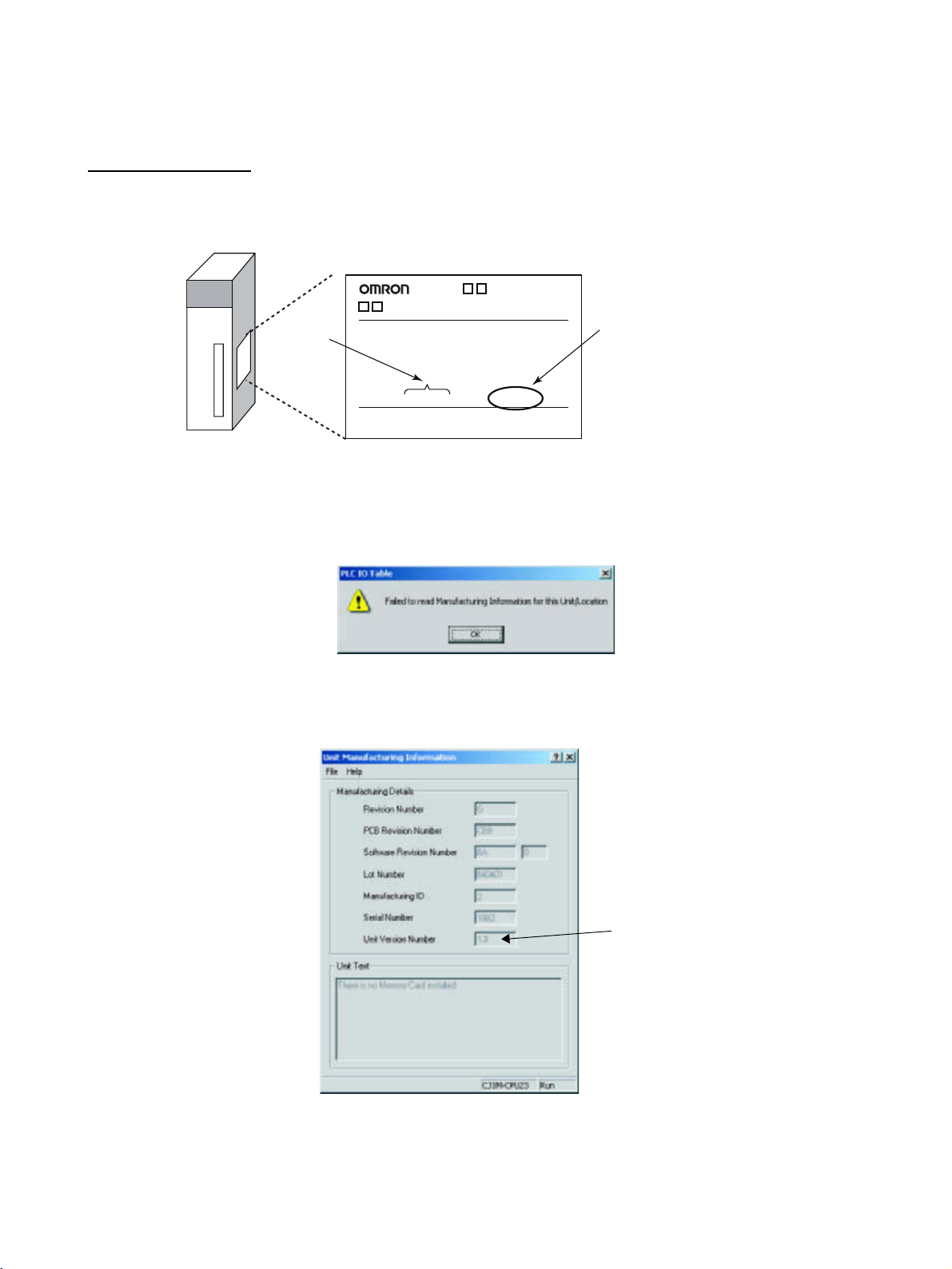
The unit version is given to the right of the lot number on the nameplate of the
products for which unit versions are being managed, as shown below.
Product nameplate
CS1W-
UNIT
Lot No.
Lot No. 040401 0000 Ver.1.3
OMRON Corporation MADE IN JAPAN
Unit version
Example for unit version 1.3
CX-Programmer version 4.0 can be used to confirm the unit version using the
Unit Manufacturing Information.
Note The unit versions of Pre-Ver.2.0 Units cannot be confirmed in Unit Manufac-
turing Information. The following dialog box is displayed.
In the IO Table Window, right-click and select Unit Manufacturing informa-
tion - CPU Unit.
The following Unit Manufacturing information Dialog Box will be displayed.
Unit version
Use the above display to confirm the unit version of the Unit connected online.
xix
Page 18

Using Unit Version Label The following unit version label is provided with the Ethernet Unit.
This label can be attached to the front of the Ethernet Unit to differentiate
between Ethernet Units with different unit versions.
Unit Version Notation In this manual, the unit version of a Ethernet Unit is given as shown in the fol-
lowing table.
Product nameplate Notation used in this manual Special remarks
Ver. 2.0 or later number
shown to right of the lot
number
Blank to the right of lot
number
Ethernet Unit Ver. 1.3 or later Information without reference to specific Unit
Versions applies to all versions of the Unit.
Pre-Ver. 1.3 Ethernet Units
Unit Versions and Lot Numbers
Type Model Date of manufacture
March 2003 or earlier April 2004 or later
Special I/O Unit Ethernet Unit CS1W-ETN21
CJ1W-ETN21
Supported Software CX-Programmer WS02-CXPC1-JV@ Ver. 3.3 or earlier Ver. 4. 0
No version code Unit Ver. 1.3
(Lot No.: 040401)
xx
Page 19

PRECAUTIONS
This section provides general precautions for using the CS1W-ETN21 and CJ1W-ETN21 Ethernet Units (100Base-TX).
The information contained in this section is important for the safe and reliable application of Ethernet Units. You
must read this section and understand the information contained before attempting to set up or operate an Ethernet
Unit.
1 Intended Audience . . . . . . . . . . . . . . . . . . . . . . . . . . . . . . . . . . . . . . . . . . . . . xxii
2 General Precautions . . . . . . . . . . . . . . . . . . . . . . . . . . . . . . . . . . . . . . . . . . . . xxii
3 Safety Precautions. . . . . . . . . . . . . . . . . . . . . . . . . . . . . . . . . . . . . . . . . . . . . . xxii
4 Operating Environment Precautions . . . . . . . . . . . . . . . . . . . . . . . . . . . . . . . . xxiv
5 Application Precautions . . . . . . . . . . . . . . . . . . . . . . . . . . . . . . . . . . . . . . . . . xxiv
6 Conformance to EC Directives . . . . . . . . . . . . . . . . . . . . . . . . . . . . . . . . . . . . xxvi
6-1 Applicable Directives . . . . . . . . . . . . . . . . . . . . . . . . . . . . . . . . . . . . xxvi
6-2 Concepts . . . . . . . . . . . . . . . . . . . . . . . . . . . . . . . . . . . . . . . . . . . . . . xxvi
xxi
Page 20

Intended Audience 1
1 Intended Audience
This manual is intended for the following personnel, who must also have
knowledge of electrical systems (an electrical engineer or the equivalent).
• Personnel in charge of installing FA systems.
• Personnel in charge of designing FA systems.
• Personnel in charge of managing FA systems and facilities.
2 General Precautions
The user must operate the product according to the performance specifications described in the operation manuals.
Before using the product under conditions which are not described in the
manual or applying the product to nuclear control systems, railroad systems,
aviation systems, vehicles, combustion systems, medical equipment, amusement machines, safety equipment, and other systems, machines, and equipment that may have a serious influence on lives and property if used
improperly, consult your OMRON representative.
Make sure that the ratings and performance characteristics of the product are
sufficient for the systems, machines, and equipment, and be sure to provide
the systems, machines, and equipment with double safety mechanisms.
This manual provides information for programming and operating the Unit. Be
sure to read this manual before attempting to use the Unit and keep this manual close at hand for reference during operation.
!WARNING It is extremely important that a PLC and all PLC Units be used for the speci-
fied purpose and under the specified conditions, especially in applications that
can directly or indirectly affect human life. You must consult with your
OMRON representative before applying a PLC System to the above-mentioned applications.
3 Safety Precautions
!WARNING Do not attempt to take any Unit apart while the power is being supplied. Doing
so may result in electric shock.
!WARNING Do not touch any of the terminals or terminal blocks while the power is being
supplied. Doing so may result in electric shock.
!WARNING Do not attempt to disassemble, repair, or modify any Units. Any attempt to do
so may result in malfunction, fire, or electric shock.
xxii
Page 21

Safety Precautions 3
!WARNING Provide safety measures in external circuits (i.e., not in the Programmable
Controller), including the following items, to ensure safety in the system if an
abnormality occurs due to malfunction of the PLC or another external factor
affecting the PLC operation. Not doing so may result in serious accidents.
• Emergency stop circuits, interlock circuits, limit circuits, and similar safety
measures must be provided in external control circuits.
• The PLC will turn OFF all outputs when its self-diagnosis function detects
any error or when a severe failure alarm (FALS) instruction is executed.
As a countermeasure for such errors, external safety measures must be
provided to ensure safety in the system.
• The PLC outputs may remain ON or OFF due to deposits on or burning of
the output relays, or destruction of the output transistors. As a countermeasure for such problems, external safety measures must be provided
to ensure safety in the system.
• When the 24-V DC output (service power supply to the PLC) is overloaded or short-circuited, the voltage may drop and result in the outputs
being turned OFF. As a countermeasure for such problems, external
safety measures must be provided to ensure safety in the system.
!Caution Execute online editing only after confirming that no adverse effects will be
caused by extending the cycle time. Otherwise, the input signals may not be
readable.
• Emergency stop circuits, interlock circuits, limit circuits, and similar safety
measures must be provided in external control circuits.
!Caution Fail-safe measures must be taken by the customer to ensure safety in the
event of incorrect, missing, or abnormal signals caused by broken signal lines,
momentary power interruptions, or other causes. Serious accidents may
result from abnormal operation if proper measures are not provided.
!Caution Confirm safety at the destination node before changing or transferring to
another node the contents of a program, the PLC Setup, I/O tables, or I/O
memory. Changing or transferring any of these without confirming safety may
result in injury.
!Caution Tighten the screws on the terminal block of the AC Power Supply Unit to the
torque specified in the operation manual. The loose screws may result in
burning or malfunction.
xxiii
Page 22

Operating Environment Precautions 4
4 Operating Environment Precautions
!Caution Do not operate the control system in the following locations:
• Locations subject to direct sunlight.
• Locations subject to temperatures or humidity outside the range specified
in the specifications.
• Locations subject to condensation as the result of severe changes in temperature.
• Locations subject to corrosive or flammable gases.
• Locations subject to dust (especially iron dust) or salts.
• Locations subject to exposure to water, oil, or chemicals.
• Locations subject to shock or vibration.
!Caution Take appropriate and sufficient countermeasures when installing systems in
the following locations:
• Locations subject to static electricity or other forms of noise.
• Locations subject to strong electromagnetic fields.
• Locations subject to possible exposure to radioactivity.
• Locations close to power supplies.
5 Application Precautions
Observe the following precautions when using the Ethernet Unit.
!WARNING Always heed these precautions. Failure to abide by the following precautions
could lead to serious or possibly fatal injury.
• Always connect to a ground of 100
connecting to a ground of 100
• Always turn OFF the power supply to the CPU Unit and Slaves before
attempting any of the following. Not turning OFF the power supply may
result in malfunction or electric shock.
• Mounting or dismounting I/O Units, CPU Units, Memory Packs, or
Master Units.
• Assembling the Units.
• Setting DIP switches or rotary switches.
• Connecting cables or wiring the system.
• Connecting or disconnecting the connectors.
!Caution Failure to abide by the following precautions could lead to faulty operation of
the Ethernet Unit or the system, or could damage the Ethernet Unit. Always
heed these precautions.
Ω or less when installing the Units. Not
Ω or less may result in electric shock.
xxiv
• Interlock circuits, limit circuits, and similar safety measures in external circuits (i.e., not in the Programmable Controller) must be provided by the
customer.
Page 23

Application Precautions 5
• Always use the power supply voltages specified in the operation manuals.
An incorrect voltage may result in malfunction or burning.
• Take appropriate measures to ensure that the specified power with the
rated voltage and frequency is supplied. Be particularly careful in places
where the power supply is unstable. An incorrect power supply may result
in malfunction.
• Install external breakers and take other safety measures against short-circuiting in external wiring. Insufficient safety measures
• Make sure that all the Backplane mounting screws, terminal block screws,
and cable connector screws are tightened to the torque specified in the
relevant manuals. Incorrect tightening torque may result in malfunction.
• Leave the label attached to the Unit when wiring. Removing the label may
result in malfunction if foreign matter enters the Unit.
• Remove the label after the completion of wiring to ensure proper heat dissipation. Leaving the label attached may result in malfunction.
• Use crimp terminals for wiring. Do not connect bare stranded wires
directly to terminals. Connection of bare stranded wires may result in
burning.
• Observe the following precautions when wiring the communications
cable.
• Separate the communications cables from the power lines or high-tension lines.
• Do not bend the communications cables past their natural bending radius.
• Do not pull on the communications cables.
• Do not place heavy objects on top of the communications cables.
• Always lay communications cable inside ducts.
• Use appropriate communications cables.
• Make sure that the terminal blocks, expansion cable connectors, and
other items with locking devices are locked in place.
• Wire all connections correctly according to instructions in this manual.
• Double-check all wiring and switch settings before turning ON the power
supply. Incorrect wiring may result in burning.
• Mount Units only after checking terminal blocks and connectors completely.
• Check the user program for proper execution before actually running it on
the Unit. Not checking the program may result in unexpected operation.
• Confirm that no adverse effect will occur in the system before attempting
any of the following. Not doing so may result in an unexpected operation.
• Changing the operating mode of the PLC.
• Force-setting/force-resetting any bit in memory.
• Changing the present value of any word or any set value in memory.
• After replacing Units, resume operation only after transferring to the new
CPU Unit and/or Special I/O Units the contents of the DM Area, HR Area,
programs, parameters, and other data required for resuming operation.
Not doing so may result in an unexpected operation.
• Before touching a Unit, be sure to first touch a grounded metallic object in
order to discharge any static build-up. Not doing so may result in malfunction or damage.
xxv
Page 24

Conformance to EC Directives 6
• When transporting the Unit, use special packing boxes and protect it from
being exposed to excessive vibration or impacts during transportation.
• CPU Bus Units will be restarted when routing tables are transferred from
a Programming Device to the CPU Unit. Restarting these Units is required
to read and enable the new routing tables. Confirm that the system will
not be adversely affected before allowing the CPU Bus Units to be reset.
6 Conformance to EC Directives
6-1 Applicable Directives
•EMC Directives
• Low Voltage Directive
6-2 Concepts
EMC Directives
OMRON devices that comply with EC Directives also conform to the related
EMC standards so that they can be more easily built into other devices or the
overall machine. The actual products have been checked for conformity to
EMC standards (see the following note). Whether the products conform to the
standards in the system used by the customer, however, must be checked by
the customer.
EMC-related performance of the OMRON devices that comply with EC Directives will vary depending on the configuration, wiring, and other conditions of
the equipment or control panel on which the OMRON devices are installed.
The customer must, therefore, perform the final check to confirm that devices
and the overall machine conform to EMC standards.
Note Applicable EMS (Electromagnetic Susceptibility) and EMI (Electromagnetic
Interference) Standards in the EMC (Electromagnetic Compatibility) standards are as follows:
Ethernet Unit EMS EMI
CS1W-ETN21
CJ1W-ETN21
Low Voltage Directive
Always ensure that devices operating at voltages of 50 to 1,000 V AC and 75
to 1,500 V DC meet the required safety standards for the PLC (EN61131-2).
EN61000-6-2
EN61000-6-4
(Radiated emission: 10-m
regulations)
xxvi
Page 25

SECTION 1
Introduction
This section introduces the functions and protocols used in Ethernet Unit communications services.
1-1 Ethernet Unit Communications Services . . . . . . . . . . . . . . . . . . . . . . . . . . . . 2
1-2 Functions Listed by Purpose. . . . . . . . . . . . . . . . . . . . . . . . . . . . . . . . . . . . . . 2
1-3 Table of Protocols . . . . . . . . . . . . . . . . . . . . . . . . . . . . . . . . . . . . . . . . . . . . . . 3
1-4 Common Protocol Settings . . . . . . . . . . . . . . . . . . . . . . . . . . . . . . . . . . . . . . . 4
1-4-1 SMTP . . . . . . . . . . . . . . . . . . . . . . . . . . . . . . . . . . . . . . . . . . . . . . . . 4
1-4-2 POP. . . . . . . . . . . . . . . . . . . . . . . . . . . . . . . . . . . . . . . . . . . . . . . . . . 5
1-4-3 DNS . . . . . . . . . . . . . . . . . . . . . . . . . . . . . . . . . . . . . . . . . . . . . . . . . 6
1
Page 26

Ethernet Unit Communications Services Section 1-1
1-1 Ethernet Unit Communications Services
Service Main functions Counterpart device Reference
Mail send function Through intranet or
internet
Mail receive function
FTP server function
Socket service
function
Automatic clock
adjust function
FINS communications
Through intranet or
internet (See note.)
Through intranet Used to automatically adjust the PLC's
Through intranet or
internet (See note.)
Used to e-mail specified I/O memory
data or a file (up to 1 MB) from the
PLC to the computer automatically
when a preset condition is met.
Used to perform operations in the PLC
from the computer, such as reading or
writing I/O memory data, backing up
data, changing the operating mode, or
transferring files (up to 1 MB).
Used to transfer large files between
the computer and PLC.
Used to transfer data between general-purpose applications and the
PLC.
internal clock.
Used to access the PLC from a computer (FINS application) or send message communications from one PLC
to another.
Note The PLC can be accessed with
FINS message communications
even from a DHCP client computer or computer with an
unspecified FINS node address.
Computer
(E-mail software)
Computer
(E-mail software)
Computer
(FTP client software)
Computer
(General applications that do not use
FINS communications)
SNTP Server SECTION 5
Computer
(User-created FINS
communications
application)
SECTION 2 Mail
Send Function
SECTION 3
Receive Mail
Function
SECTION 4
FTP Server
SECTION 6
Socket Services
Automatic Clock
Adjustment
Function
SECTION 7
Using FINS
Communications to Create
Host Applications
Note When transferring data through the internet, a global IP address must be
acquired for the Ethernet Unit.
1-2 Functions Listed by Purpose
Timing and
direction
User-specified timing, sent from computer
User purpose Communications
Reading and writing
data in the CPU Unit's
I/O memory
Changing the CPU
Unit's operating mode
Performing operations
on EM file memory or
a Memory Card
installed in the CPU
Unit
Backing up the user
program or parameter
area in the CPU Unit
Reading or clearing
the error log in the
Ethernet Unit or CPU
Unit
Sending a specific
FINS command to a
specific Unit
service
Mail Receive
Function
Method Restrictions
IOMRead (I/O memory read) and
IOMWrite (I/O memory write) commands
ChangeMode command ---
FileWrite, FileRead, FileDelete,
and FileList commands
UMBackup (User program backup)
and PARAMBackup (Parameter
area backup) commands
ErrorLogRead and ErrorLogClear
commands
FinsSend command ---
The maximum data
size is 6,000
words.
The maximum data
size is 1 MB.
---
---
2
Page 27

Table of Protocols Section 1-3
Timing and
direction
Automatic execution when a preset
condition is met,
sent to computer
(See note.)
User-specified timing, sent from computer
Performed at a set
time every day or
from the ladder
program
Temporarily connecting a computer
to perform operations from a FINS
application such as
the CX-Programmer
Performing operations from two or
more FINS applications in the computer
User purpose Communications
Reading data in the
CPU Unit's I/O memory
Reading data from a
Memory Card installed
in the CPU Unit
Receiving a userdefined message as
an e-mail
Performing operations
on EM file memory or
a Memory Card
installed in the CPU
Unit
Reading and writing
data in the CPU Unit's
I/O memory from a
general application
(not using FINS communications)
Automatically correcting the PLC's internal
clock
Performing online
operations on the CPU
Unit
service
Mail Send Function
FTP Server Function
Socket Service
Function
Automatic Clock
Adjust Function
FINS communications
Method Restrictions
Specify a data file as an attached
file and specify the starting read
address and number of words.
Specify any file as an attached file. The maximum data
Store the desired message in
ASCII in the CPU Unit's I/O memory.
Login to the Ethernet Unit from the
FTP client software and send the
FTP command.
Socket service operations can be
executed by executing the CMND
instruction or setting control bits in
the PLC.
Install the SNTP server in the network and schedule the synchronization time in the Ethernet Unit.
One function stores the counterpart FINS nodes' connection information. Another function
automatically assigns node
addresses.
A function supports simultaneous
online connections of multiple
applications in the computer.
The maximum data
size is 6,000
words.
size is 1 MB.
The maximum
message length is
1,024 characters
(alphanumeric
characters only).
The data size is not
restricted. The IP
address for the
Ethernet Unit must
be private and
fixed.
The IP address for
the Ethernet Unit
must be private
and fixed.
---
The IP address for
the Ethernet Unit
must be private
and fixed.
---
Note Any one of the following conditions can be specified to send e-mail automati-
cally:
A periodic timer times out, the Mail Send Switch is turned from OFF to ON, a
specified word contains a particular value, a specified bit turns from OFF to
ON, the CPU Unit's operating mode changes, a fatal error occurs, or an event
is stored in the error log.
1-3 Table of Protocols
Communications
service
Mail Send Function SMTP Required SMTP SECTION 2 Mail
Protocol used Situation when used CX-
Programmer's
Unit setting tag
name
POP When using “POP before SMTP” POP
DNS When specifying the SMTP server and
POP server by host names
DNS
Reference
Send Function
3
Page 28
Common Protocol Settings Section 1-4
Communications
service
Mail Receive Function SMTP Required SMTP SECTION 3
FTP Server Function FTP Optional User set SECTION 4
Socket Service Function
Automatic Clock
Adjust Function
Creating a FINS communications host
application
Protocol used Situation when used CX-
POP Required POP
DNS When specifying the SMTP server and
POP server by host names
TCP/IP Optional User set SECTION 6
UDP/IP Optional User set
SNTP Required Automatic clock
DNS When specifying the SNTP server by a
host name
FINS Optional User set SECTION 7
Programmer's
Unit setting tag
name
DNS
synchronization
DNS
Reference
Receive Mail
Function
FTP Server
Socket Services
SECTION 5
Automatic Clock
Adjustment
Function
Using FINS
Communications to Create
Host Applications
1-4 Common Protocol Settings
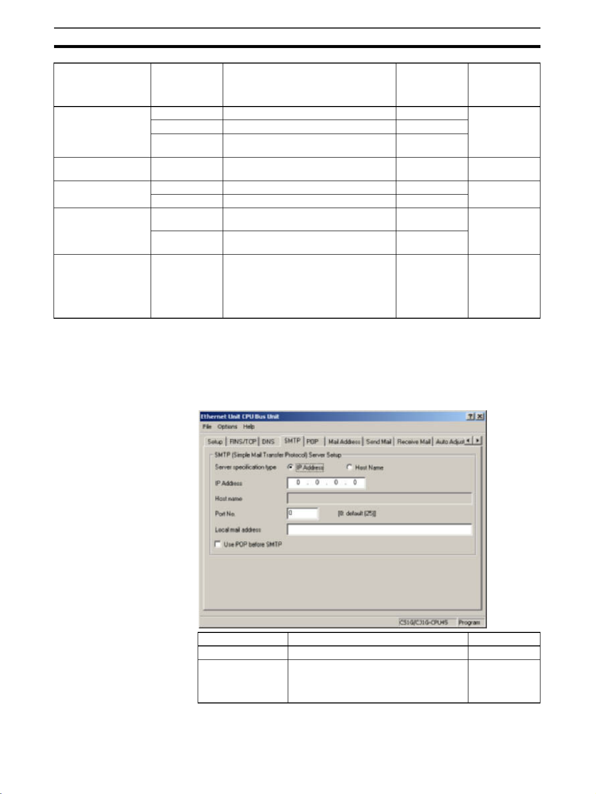
1-4-1 SMTP
The SMTP server settings must be made in order to use the Mail Send Function or Mail Receive Function.
Item Contents Default
Local mail address Set the mail address for the Ethernet Unit. None
Server specification
type
Select whether the SMTP server used for
sending mail is to be specified by IP
address or the host's domain name (i.e.,
host name).
IP Address
4
Page 29

Common Protocol Settings Section 1-4
Item Contents Default
IP Address Set the IP address for the SMTP server
Host name Set the host domain name (i.e., the host
Port No. Set the port to be used for connecting to the
Use POP before
SMTP
used for sending mail.
This setting is enabled only when “IP
address” is selected as the method for
specifying the server.
name) for the SMTP server that is to be
used for sending mail.
This setting is enabled only when “host
name” is selected as the method for specifying the server.
SMTP server that is to be used for sending
mail.
This setting does not normally need to be
changed.
Select whether or not to use the mail receiving method (POP before SMTP) in which
the POP server must be accessed (to
receive mail) before the SMTP server is
accessed (to send mail).
Note The “POP before SMTP” is an authentication function required when sending
mail (using the SMTP server). Normally, account name and password authentication is performed with the POP server because there isn't an authentication process in the SMTP server. Most ISPs (Internet Service Providers) use
the “POP before SMTP” authentication method to verify users sending e-mail.
0.0.0.0
None
0
(No. 25 is used.)
Disabled
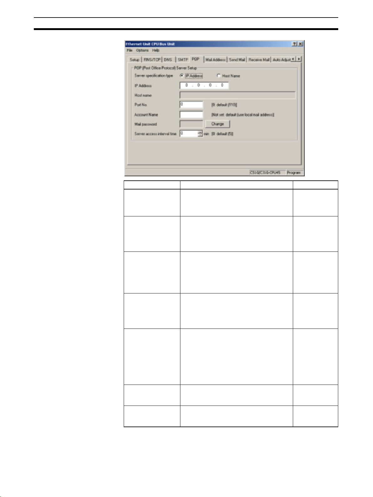
1-4-2 POP
Always enter the POP server settings when using the Mail Receive Function.
Also, set the POP server settings when using “POP before SMTP” in the Mail
Send Function.
5
Page 30
Common Protocol Settings Section 1-4
Item Contents Default
Server specification
type
IP Address Set the IP address for the POP3 server
Host name Set the host domain name (i.e., the host
Port No. Set the port to be used for connecting to the
Account Name Sets the account name (up to 9 characters)
Mail password Sets the password (up to 8 characters) of
Server access interval time
Select whether the POP3 server used for
receiving mail is to be specified by IP
address or the host's domain name (i.e.,
host name).
used for receiving mail.
This setting is enabled only when “IP
address” is selected as the method for
specifying the server.
name) for the POP3 server that is to be
used for receiving mail.
This setting is enabled only when “host
name” is selected as the method for specifying the server.
POP3 server that is to be used for receiving
mail.
This setting does not normally need to be
changed.
of the account used to send and receive email.
Only alphanumeric characters can be used.
If no account name is set, the portion of the
local e-mail address to the left of the @ will
be used. In this case, the number of characters in the account name is not restricted.
the account used to send and receive email.
Set the interval for sending and receiving
mail. Mail will be automatically sent and
received at the interval set here.
IP Address
0.0.0.0
None
0
(Number 110 is
used.)
None
None
0
(5 minutes)
1-4-3 DNS
6
The DNS server's settings must be entered when the POP3 server, SMTP
server, and SNTP server are specified with host names.
Page 31

Common Protocol Settings Section 1-4
The DNS server manages the IP addresses and host names of the nodes that
communicate in the network. The Ethernet Unit automatically acquires each
server's IP address from the DNS server and uses those acquired IP
addresses.
Item Contents Default
IP Address Set the IP address for the DNS server. None
Port No. Set the port to be used for connecting to the
DNS server. Normally, the default setting is
used.
Retry Timer Set the time to elapse before retrying when
a connection to the DNS server fails. Normally, the default setting is used.
Units: Seconds
Number of retries: Fixed at 3
0
(Number 53 is
used.)
0
(Sets 10 seconds.)
7
Page 32

Common Protocol Settings Section 1-4
8
Page 33

SECTION 2
Mail Send Function
This section provides an overview and describes how to use the Ethernet Unit’s Mail Send Function, including application
examples and troubleshooting information.
2-1 Mail Send Function Overview . . . . . . . . . . . . . . . . . . . . . . . . . . . . . . . . . . . . 10
2-1-1 Introduction. . . . . . . . . . . . . . . . . . . . . . . . . . . . . . . . . . . . . . . . . . . . 10
2-1-2 Comparison with the Earlier Mail Send Function . . . . . . . . . . . . . . 11
2-1-3 Mail Send Function's Compatibility with Earlier Models . . . . . . . . 11
2-2 Mail Send Function Details. . . . . . . . . . . . . . . . . . . . . . . . . . . . . . . . . . . . . . . 11
2-2-1 Contents of E-mail Body . . . . . . . . . . . . . . . . . . . . . . . . . . . . . . . . . 12
2-2-2 Contents of E-mail Body . . . . . . . . . . . . . . . . . . . . . . . . . . . . . . . . . 13
2-2-3 Attached File Details . . . . . . . . . . . . . . . . . . . . . . . . . . . . . . . . . . . . 15
2-2-4 Summary of E-mail Body Information and Attached Files . . . . . . . 16
2-3 Mail Send Function Specifications . . . . . . . . . . . . . . . . . . . . . . . . . . . . . . . . . 17
2-3-1 Function Specifications . . . . . . . . . . . . . . . . . . . . . . . . . . . . . . . . . . 17
2-3-2 Details of the Available Mail Triggers . . . . . . . . . . . . . . . . . . . . . . . 18
2-4 Using the Mail Send Function . . . . . . . . . . . . . . . . . . . . . . . . . . . . . . . . . . . . 18
2-4-1 Procedure . . . . . . . . . . . . . . . . . . . . . . . . . . . . . . . . . . . . . . . . . . . . . 18
2-4-2 Settings Required for the Mail Send Function . . . . . . . . . . . . . . . . . 19
2-4-3 Mail Address. . . . . . . . . . . . . . . . . . . . . . . . . . . . . . . . . . . . . . . . . . . 21
2-4-4 Send Mail . . . . . . . . . . . . . . . . . . . . . . . . . . . . . . . . . . . . . . . . . . . . . 21
2-5 Mail Send Function Status . . . . . . . . . . . . . . . . . . . . . . . . . . . . . . . . . . . . . . . 24
2-5-1 Send Mail Status . . . . . . . . . . . . . . . . . . . . . . . . . . . . . . . . . . . . . . . . 24
2-5-2 Mail Send Switch, Accessing Memory/Sending Mail Flag . . . . . . . 25
2-6 I/O Memory Data Formats . . . . . . . . . . . . . . . . . . . . . . . . . . . . . . . . . . . . . . . 26
2-7 Attached File Transfer Times . . . . . . . . . . . . . . . . . . . . . . . . . . . . . . . . . . . . . 27
2-8 Mail Send Function Errors . . . . . . . . . . . . . . . . . . . . . . . . . . . . . . . . . . . . . . . 28
2-8-1 Identifying and Correcting Mail Send Function Errors . . . . . . . . . . 28
2-8-2 Troubleshooting Mail Send Errors with LED Indicators . . . . . . . . . 29
2-8-3 Error Log Error Codes for the Mail Send Function . . . . . . . . . . . . . 29
2-9 Example Application. . . . . . . . . . . . . . . . . . . . . . . . . . . . . . . . . . . . . . . . . . . . 30
2-9-1 Step 1. Create the I/O Table . . . . . . . . . . . . . . . . . . . . . . . . . . . . . . . 30
2-9-2 Step 2. Make the Unit Setup Settings from the CX-Programmer. . . 30
2-9-3 Step 3. Transfer the CPU Bus Unit Setup Settings. . . . . . . . . . . . . . 32
2-9-4 Step 4. Automatic Transmission when Send Condition is Satisfied. 32
9
Page 34
Mail Send Function Overview Section 2-1
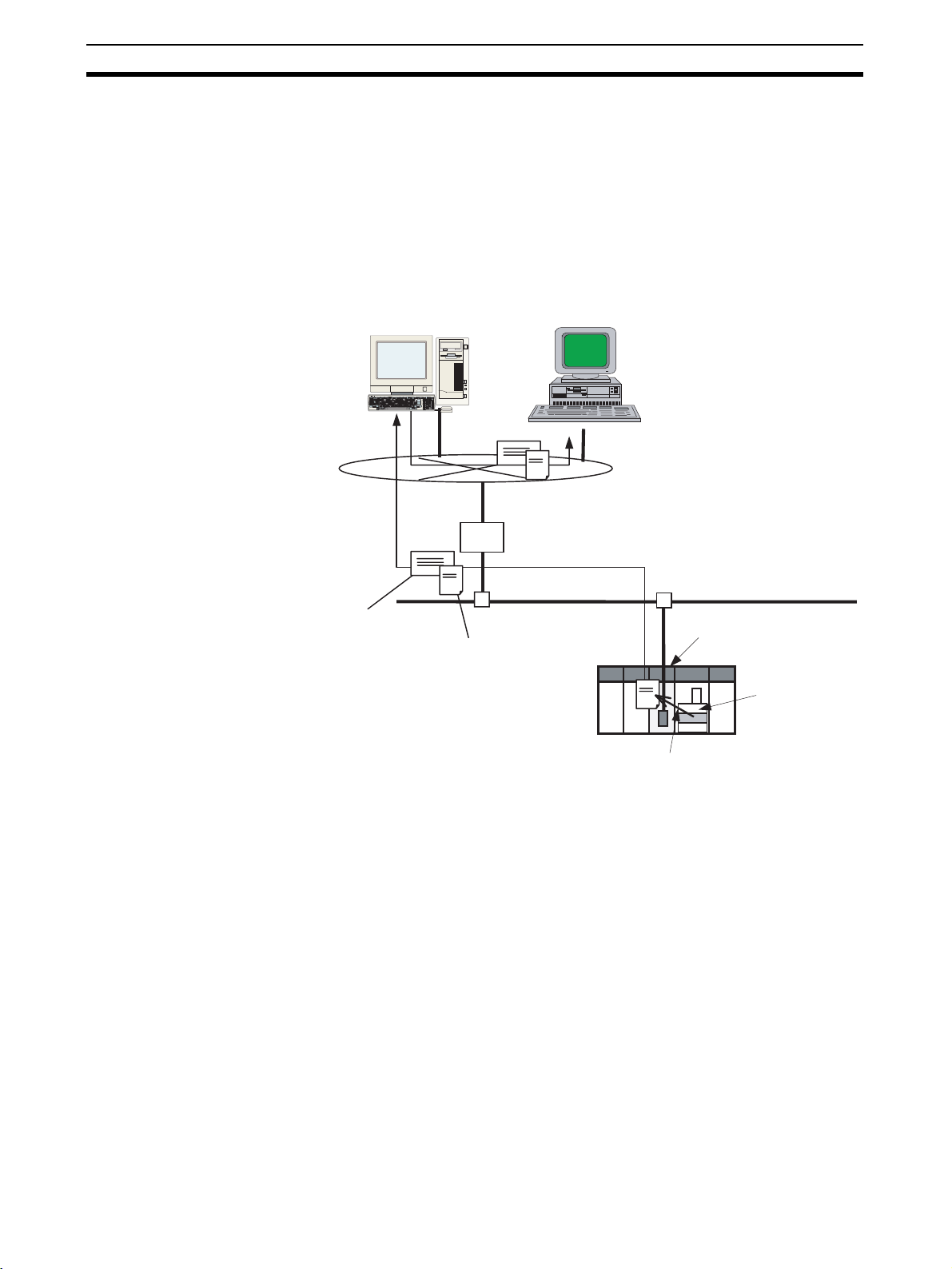
2-1 Mail Send Function Overview
2-1-1 Introduction
The Mail Send Function sends an e-mail from the Ethernet Unit to a specified
e-mail address when a predetermined condition occurs in the PLC.
Data in the CPU Unit's I/O memory areas (or any file in the Memory Card) can
be sent as an attached file.
In addition, user-set ASCII information as well as the Ethernet Unit's error log
and status information can be sent as text in the body of the e-mail.
Internet or
intranet
E-mail
Body: User
information,
error log, or
Unit status
SMTP server
User
E-mail
E-mail reception
Router
Sent automatically when
preset condition is met.
Ethernet
Ethernet Unit
Attached file:
Specified I/O memory
file in CPU Unit
I/O memory
The Ethernet Unit converts the
specified I/O memory data to a file.
Advantages A specific range of I/O memory data in the CPU Unit can be sent automati-
cally as an attached file (through the internet or intranet) when a particular
condition occurs. Some conditions that can be used are a bit turning ON to
indicate an error, a specified word containing a given value, or a periodic time
being reached.
E-mails can be sent when various conditions in the existing ladder program
are met. It is not necessary to modify the existing ladder program.
The Mail Send Function can be used to create various applications such as
error monitoring of remote equipment, periodic monitoring of equipment, and
quality control applications.
Description When a specified sending condition is met, the following e-mail body data and
attached files can be sent automatically as an e-mail to the e-mail address
specified in the CPU Bus Unit System Setup.
■ Body Data
Any desired combination of user-set information (any ASCII character string),
error log information, and status information can be sent.
10
Page 35

Mail Send Function Details Section 2-2
■ Attached Files
An I/O memory data file created automatically by the Ethernet Unit (a specified range of the CPU Unit's I/O memory data converted to a .IOM, .TXT, or
.CSV file) or any file in file memory (in the CPU Unit's Memory Card) can be
sent as an attached file.
■ Send Timing
An e-mail can be sent automatically when a dedicated control bit goes from
OFF to ON, a specified word's value meets a preset condition, a specified bit's
status changes, an entry is recorded in the Ethernet Unit's error log, the CPU
Unit's status changes (a non-fatal error occurs, a fatal error occurs, or the
operating mode changes), or at periodic intervals.
■ Send Mail Conditions
Up to 8 send mail conditions can be preset to send an e-mail automatically
when the specified conditions are met. Conditions include the send destination, trigger type, I/O memory addresses to be converted to a data file or the
name of the file to be read from file memory, and periodic sending interval.
2-1-2 Comparison with the Earlier Mail Send Function
Item Earlier version Current version
Model CS1W-ETN01/11
Attached file Not supported. Supported.
Send mail conditions
and CJ1W-ETN11
Any of the following:
A dedicated control
bit (the Mail Send
Switch) goes OFF to
ON, the status of the
Ethernet Unit
changes (an entry is
recorded in the error
log), periodic timer
CS1W/CJ1W-ETN21
A range of I/O memory data can be converted to a data file and attached, a file in a
Memory Card mounted in the CPU Unit can
be attached, or a file in the CPU Unit's EM
file memory can be attached.
Any of the following:
• A dedicated control bit (Mail Send Switch)
goes OFF-to-ON.
• A specified word's value changes (=, <>,
<, <=, >=, or > condition).
• A specific bit changes (OFF-to-ON or ONto-OFF).
• Ethernet Unit changes (entry in error log).
• CPU Unit changes (non-fatal error occurs,
fatal error occurs, or operating mode
changes).
• Periodic timer
2-1-3 Mail Send Function's Compatibility with Earlier Models
When a CS1W-ETN21 or CJ1W-ETN21 is used to replace a CS1W-ETN01/
11 or CJ1W-ETN11 Ethernet Unit in an application, the Unit's functions are
downwardly compatible if the following status bits are used.
ETN01/11 ETN21
User mail send status Status of send condition setting 5
Periodic mail send status Status of send condition setting 6
Error mail send status Status of send condition setting 7
2-2 Mail Send Function Details
The Mail Send Function can send information in the body of the e-mail as well
as in an attached file.
11
Page 36

Mail Send Function Details Section 2-2
2-2-1 Contents of E-mail Body
Date and time
Ethernet Unit's e-mail address
Date: Fri, 1 Jan 2004 13:00:00 +0900
From: alpha@omron.co.jp
Message-Id: <XXXXXXXXXXX@omron.co.jp>
To: beta@omron.co.jp
Subject: OMRON Ethernet Unit Mail Service (posted at regular intervals)
Content-Type: text/plain; charset=US-ASCII
Content-Transfer-Encoding: 7bit
Header
Trigger Setting Number = 1
This is OMRON ethernet unit mail posting service.
This mail have been posted at regular intervals.
======================================================================
Ethernet Unit Identification
======================================================================
Model : CS1W-ETN21
Version : VX.XX
IP address : XXX.XXX.XXX.XXX
Subnet mask : XXX.XXX.XXX.XXX
IP conversion : Table used
======================================================================
User Message
======================================================================
TEST MAIL.
======================================================================
Error Log Information
======================================================================
MM/DD/YY HH:MM:SS Error Detail Description
-------- -------- ---- ---- -----------------------------------03/05/29 12:00:00 0006 0000 CPU unit error
03/05/29 12:30:00 0121 0101 Destination IP address not registered
======================================================================
Status Information
======================================================================
*Error Status
IP router table error : OFF
IP address setting error : OFF
IP address table error : OFF
Routing table error : OFF
Address mismatch : OFF
EEP-ROM error : OFF
Body
POP server error : OFF
SMTP server error : OFF
SNTP server error : OFF
DNS server error : OFF
----------------------------------------------------*UDP Socket Connection Status
UDP Socket No.1 connection status : Opened
UDP Socket No.2 connection status : Closed
UDP Socket No.3 connection status : Closed
UDP Socket No.4 connection status : Closed
UDP Socket No.5 connection status : Closed
UDP Socket No.6 connection status : Closed
UDP Socket No.7 connection status : Closed
UDP Socket No.8 connection status : Closed
----------------------------------------------------*TCP Socket Connection Status
TCP Socket No.1 connection status : Established
TCP Socket No.2 connection status : Closed
TCP Socket No.3 connection status : Closed
TCP Socket No.4 connection status : Closed
TCP Socket No.5 connection status : Closed
TCP Socket No.6 connection status : Closed
TCP Socket No.7 connection status : Closed
TCP Socket No.8 connection status : Closed
----------------------------------------------------*Number Information
Total number of receive packets : 123,456
Total number of receive errors : 0
Total number of send packets : 234,567
Total number of send errors : 0
Total number of send collisions : 0
Destination e-mail address
Title (depends on trigger condition)
Content-Type (fixed)
Trigger number (required)
Trigger information (required)
Ethernet Unit model (required)
Unit version (required)
Ethernet Unit IP address (required)
User-set information (optional)
Error log information (optional)
Status information (optional)
12
Attached file
Page 37

Mail Send Function Details Section 2-2
2-2-2 Contents of E-mail Body
Ethernet Unit's Status
Information Header
The following header information is included.
• Subject: OMRON Ethernet Unit Mail Service
(Indicates trigger condition. See
note.)
• Content-Type: text/plain;charset=US-ASCII
• Content-Transfer-Encoding:7bit
Note The following trigger conditions are available.
Trigger condition Text entered as subject
Software switch posted by user request
Change in specified
word's contents
Change in specified
bit
Change in ETN Unit posted at error occurrence
Change in CPU Unit posted at changing CPU mode
Periodic timer posted at regular intervals
posted at changing channel value(= flag)
posted at changing channel value(<> flag)
posted at changing channel value(< flag)
posted at changing channel value(<= flag)
posted at changing channel value(>= flag)
posted at changing channel value(> flag)
posted at rising edge of bit
posted at falling edge of bit
posted at CPU error occurrence(FAL)
posted at CPU error occurrence(FALS)
Trigger Information The trigger information is always included in the e-mail.
• Trigger number: 1 to 8
• Shared message: “This is OMRON ethernet unit mail posting
service.”
• Trigger-specific messages: The following messages are displayed.
Tri gge r
condition
Software switch This mail have been posted by user request
Change in
specified word's
contents (See
note.)
Change in
specified bit's
status
Change in ETN
Unit
This mail have been posted at changing channel value(=
flag)
This mail have been posted at changing channel value(<>
flag)
This mail have been posted at changing channel value(<
flag)
This mail have been posted at changing channel value(<=
flag)
This mail have been posted at changing channel value(>=
flag)
This mail have been posted at changing channel value(>
flag)
This mail have been posted at rising edge of bit
This mail have been posted at falling edge of bit
This mail have been posted at error occurrence
Trigger-specific message in e-mail header
13
Page 38

Mail Send Function Details Section 2-2
Tri gge r
condition
Change in CPU
Unit
Periodic timer This mail have been posted at regular intervals
This mail have been posted at changing CPU mode (PRG>MON)
This mail have been posted at changing CPU mode (PRG>RUN)
This mail have been posted at changing CPU mode (MON>PRG)
This mail have been posted at changing CPU mode (MON>RUN)
This mail have been posted at changing CPU mode (RUN>PRG)
This mail have been posted at changing CPU mode (RUN>MON)
This mail have been posted at changing CPU mode
(PowerON->PRG)
This mail have been posted at changing CPU mode
(PowerON->MON)
This mail have been posted at changing CPU mode
(PowerON->RUN)
This mail have been posted at CPU error occurrence(FAL)
This mail have been posted at CPU error occurrence(FALS)
Trigger-specific message in e-mail header
Note Another sentence will be attached indicating how the specified
word's value has changed: “Channel data has changed from XX to
XX.”
Ethernet Unit Information The Ethernet Unit information is always included in the e-mail.
• Model
• Version
• IP address (decimal notation)
• Subnet mask (decimal notation)
• IP address conversion method
Optional Information The optional information that can be included in the e-mail body is listed
below.
Different information can be selected with each mail trigger, and more than
one type of information can be selected. (The selections are specified in the
CPU Bus Unit System Setup.) If no optional information is selected, the e-mail
will not be sent even when the trigger condition is met.
■ User-set Information
User-set information is ASCII text set by the user in the CPU Unit's memory.
Up to 1,024 bytes of data can be sent from the user-set mail data address set
in the CPU Bus Unit Area.
Note (a) The user-set message sent in each e-mail can be changed just
by changing the contents of the relevant words in the CPU Bus
Unit Area. To change the user-set message easily, prepare several messages in advance and copy the desired message to the
CPU Bus Unit Area when it is required.
The data set by the user is sent just as it is, and the code is not
converted.
(b) If there is a null code character (00 Hex) in the data, only the data
up to that point will be sent.
(c) The user-set data is sent as-is and the codes are not converted.
14
Page 39

Mail Send Function Details Section 2-2
■ Error Log Information
The error log information includes all of the data stored in the Ethernet Unit's
error log. The error log can contain up to 64 records. For details on the error
log, refer to 8-3 Error Log in the Operation Manual Construction of Networks
(W420).
■ Status Information
The following Ethernet Unit data is sent.
1. Open/closed status of UDP sockets 1 to 8
2. TCP status of TCP sockets 1 to 8
3. Unit error information
4. Counter information
Total number of receive packets, total number of receive errors, total number of send packets, total number of send errors, total number of send collisions
2-2-3 Attached File Details
Files that can be attached to e-mails are broadly divided into the following 2
groups.
• I/O memory data (IOM, TXT, and CSV formats)
• File data
Only one file can be attached to each e-mail.
I/O Memory Data (6,000
Words Max.)
Sends e-mail.
Ethernet
When it is time to send the e-mail, the Ethernet Unit reads the specified
amount of data starting at the specified I/O memory address in the CPU Unit,
creates a file with that data, and sends the file with the e-mail as an attachment.
Files can be created with filename extension “.IOM”, “.TXT”, or “.CSV”. These
are CS/CJ Series file memory function files.
Extension Content
.IOM This is a binary file containing the specified number of words starting at
.TXT This is a tab-delimited text file containing the specified number of words
.CSV This is a comma-delimited text file containing the specified number of
One area (Example: DM)
Start word: D00100
End word: D00119
the specified address. The words must be in the same data area.
starting at the specified address. The words must be in the same data
area.
words starting at the specified address. The words must be in the same
data area.
Data when send condition
is established.
Example
I/O memory
Data size:
E.g., 20
E-mail
D00100 1 2 3 4
D00101 5 6 7 8
D00102 9 A B C
to to
Automatically created by Ethernet Unit
Example: CSV file
Specified amount of comma-separated data
starting from the specified starting word
1234,5678,9ABC
Data file:
Example: DATA0.CSV
Sent as an attached file.
15
Page 40

Mail Send Function Details Section 2-2
• Since the Ethernet Unit creates the data file automatically, the Accessing
Memory/Sending Mail Flag (bit 01 of n+17 in the allocated CPU Bus Unit
Area) will be ON while the CPU Unit's I/O memory is being accessed.
• To maintain the integrity of the data, write-protect the region of I/O memory being converted to a data file by preventing the region from being written from the ladder program while this flag is ON.
File Data (1 MB Max.) Any file stored in the Memory Card installed in the CPU Unit (root directory
MEMCARD) can be sent with the e-mail as an attached file.
Sends e-mail.
Ethernet
Any file in the
Memory Card
Send any Windows file or a CS/CJ
format file such as a user program file
(.OBJ) or parameter file (.STD).
Memory Card
E-mail
Sent as an attached file.
• Generally, CS/CJ file memory files are attached, such as program files
(.OBJ), parameter files (.STD), and data files stored in the Memory Card
(.IOM, .TXT, or .CSV).
2-2-4 Summary of E-mail Body Information and Attached Files
Data sent Body/Attached file
E-mail body Attached file
User-set information ASCII text
(Set in the CPU Unit's I/O
memory by the user.)
Ethernet Unit's error
log
Ethernet Unit's status information
I/O memory data (up
to 6,000 words)
File data (Up to
1MB)
ASCII text
(Generated automatically by
the Ethernet Unit.)
ASCII text
(Generated automatically by
the Ethernet Unit.)
--- The Ethernet Unit automati-
--- Specify any file in the Memory
---
---
---
cally creates the data file
(.IOM, .CSV, or .TXT) when
the mail send condition (trigger setting) is established.
Card installed in the CPU
Unit.
16
Page 41

Mail Send Function Specifications Section 2-3
2-3 Mail Send Function Specifications
2-3-1 Function Specifications
Item Specifications
Destination e-mail address Up to 2 addresses can be registered in the Unit Setup (CPU Bus Unit System Setup) and
Subject Fixed text (Depends on the trigger condition.)
Body User-set information (up to 1,024 bytes), the Ethernet Unit's error log, and the Ethernet
Attached
file
Mail triggers The mail triggers can be selected in the Unit Setup (CPU Bus Unit System Setup).
Number of mail triggers Up to 8 triggers can be set and operated simultaneously.
Contents of send mail condi-
tion settings 1 to 8
Sending method
(encoding)
Encryption None
Compression None
Protocols used SMTP (port number 25: can be changed with the CX-Programmer Unit Setup)
Mail send status Transmission status information such as mail being sent, normal completion, and error
Data format Any one of the following files can be selected in the Unit Setup (CPU Bus Unit System
Data size • I/O memory data: Up to 6,000 words (The max. size is the same for all file types.)
Format MIME (version 1.0) format
Number of
attachments
the addresses can be up to 50 characters long.
Unit's status information can be included individually or in any combination.
Setup).
• I/O memory data
When the mail send condition is established, the data starting at the specified address in
the CPU Unit's I/O memory is automatically converted to a data file (.IOM, .TXT, or
.CSV) and sent as an attachment.
• File data
A Windows file with any filename extension
• File data: Up to 1 MB
Only 1 allowed
1. OFF to ON transition of a dedicated control bit (the Mail Send Switch)
2. Change in the value of a specified word (=, <>, <, <=, >=, or >)
3. Change in the status of a specified bit (OFF-to-ON or ON-to-OFF transition)
4. Change in the Ethernet Unit (event entered into the error log)
5. Change in the CPU Unit (non-fatal error occurred, fatal error occurred, or operating
mode changed)
6. Periodic timer
Note Set the monitoring interval when using triggers 2 and 3. Set the sending interval
when using trigger 6.
Make the following settings in the Unit Setup (CPU Bus Unit System Setup):
• E-mail body information (user-set information, error log, and status information)
• Attached file type (any file in file memory or data file with filename extension .IOM, .TXT,
or .CSV), attached file name
• Mail trigger type (set trigger types listed above for triggers 1 to 8, trigger data address,
and word comparison set value)
• Starting address of user-set information
• Starting address of attached I/O memory data and number of words
• Time interval (Set for mail trigger 2 change in value of specified word, mail trigger 3
change in status of specified bit, or mail trigger 6 periodic timer)
Subject: Us ASCII
Body: Us ASCII (Information types 2 through 4 can be sent in the body.)
Attached file: Base64
(The POP before SMTP method can also be set.)
completion is indicated for each of the 8 send mail condition settings in words m (Mail Status 1) and m+17 (Mail Status 2) in the DM Area words allocated to the Ethernet Unit as a
CPU Bus Unit.
17
Page 42

Using the Mail Send Function Section 2-4
2-3-2 Details of the Available Mail Triggers
Classification Trigger type
User-set Trigger when a specified word in the CPU Unit's I/O memory
Change in status
Periodic intervals
becomes equal to a set value.
Trigger when a specified word in the CPU Unit's I/O memory
becomes greater than a set value.
Trigger when a specified word in the CPU Unit's I/O memory
becomes less than a set value.
Trigger when a specified bit in the CPU Unit's I/O memory goes
from OFF to ON.
Trigger when a specified bit in the CPU Unit's I/O memory goes
from ON to OFF.
Trigger when an event is registered in the Ethernet Unit's error log.
Trigger when an error occurs in the Ethernet Unit.
Trigger when a fatal error occurs in the CPU Unit.
Trigger when a non-fatal error occurs in the CPU Unit.
Trigger when the CPU Unit's operating mode (RUN, MONITOR, or
PROGRAM) changes.
Trigger once every 10 minutes to 10 days (14,400 minutes).
2-4 Using the Mail Send Function
2-4-1 Procedure
1. Make the basic settings.
For details, refer to Section 2 Installation and Initial Setup in the Operation Manual Con-
struction of Networks.
2. Connect the CX-Programmer online and make the following settings in the Unit Setup
(CPU Bus Unit System Setup):
• SMTP Tab (required)
• POP Tab (when the Use POP before SMTP option is selected)
• DNS Tab (when using a host name)
• Mail Address Tab (Register one or two destination e-mail addresses.)
• Send Mail Tab (Register up to 8 send mail conditions and corresponding send data.)
3. Select Transfer to PLC from the Options Menu and click the Yes Button to transfer the
Unit Setup (CPU Bus Unit System Setup) to the CPU Unit. (The settings data will be
transferred to the CPU Bus Unit System Setup Area.)
4. When the preset condition is established, an e-mail will be sent automatically to the
specified destination address(es).
5. The Send Mail Status (words m and m+17 of the allocated DM Area words) can be
checked from the ladder program when necessary.
Note To preserve the simultaneity of the data when a data file is being sent as an
attachment, add a condition to write processes in the ladder program so that the
region of memory being converted to a data file is not overwritten from the ladder
program while memory is being accessed (mail is being sent). Bit 01 of word
n+17 in the allocated CIO Area words will be ON while the relevant memory is
being accessed.
↓
↓
↓
↓
18
Note The Ethernet Unit will be restarted when the settings data is transferred to the
CPU Bus Unit System Setup Area, so that the new settings are read and
Page 43

Using the Mail Send Function Section 2-4
become effective. Verify that it is safe for the Ethernet Unit to restart before
transferring the settings data.
2-4-2 Settings Required for the Mail Send Function
The following Unit settings must be made when using the Mail Send Function.
CX-
Programmer
Unit Setup
Tab
SMTP Server specification
POP
(See note 1.)
DNS
(See note 2.)
Mail Address Mail address 1 At least one e-mail address must be entered (mail address 1 or
Setting Setting requirement Reference
type
IP Address One or the other is required, depending on the Server specifi-
Host name
Port No. Rarely required (when a setting other than the default setting of
Local mail address Required.
Use POP before
SMTP
Server specification
type
IP Address One or the other is required, depending on the server specificaHost name
Port No. Rarely required (when a setting other than the default setting of
Account Name Required when the account name is different from the name up
Mail password Required.
Server access inter-
val time
IP Address Required.
Port No. Rarely required (when a setting other than the default setting of
Retry timer Optional (Change when the default setting of 10 seconds is
Mail address 2
Required. 1-4 Common
cation type setting.
25 is required).
Required when the account must be authenticated with POP3
before sending mail.
Required.
tion method setting.
110 is required).
to the @ symbol in the e-mail address.
Optional (Change when the default setting of 5 minutes is unacceptable.)
53 is required).
unacceptable.)
2).
Protocol Settings
page 21
19
Page 44

Using the Mail Send Function Section 2-4
CX-
Programmer
Unit Setup
Tab
Send Mail
(Send mail
conditions 1 to
8)
Setting Setting requirement Reference
Trigger type One type must be selected.
• Rising edge of the Mail Send Switch: Select the Software
switch Option.
• Change in specified word's value: Select the Word value
change Option and specify the Area, Address, Val ue, and
State.
• Change in specified bit's status: Select the Bit value change
Option and specify the Area, Address, Bit, and State.
• Entry in Ethernet Unit's error log: Select the ETN condition
Option.
• Change in CPU Unit status: Select the CPU condition Option.
• Sending mail at periodic intervals: Select the Periodic timer
Option.
Interval time Required when the trigger type is set to Word value change, Bit
Mail address (destination)
Send user data Required to send a user-set ASCII message in the e-mail body.
Send Error Log infor-
mation
Send status informa-
tion
IO memory data Required when the Send file data/IO memory data Option has
Attached file name Required when the Send file data/IO memory data Option has
value change, or Periodic timer.
Required.
Required to send the error log information in the e-mail body.
Required to send the Ethernet Unit's status in the e-mail body.
been selected and a data file is being attached (IO data (IOM),
IO data (CSV), or IO data (TXT)).
been selected.
page 21
Note (1) Make POP settings when the Use POP before SMTP Option was select-
ed in the SMTP Tab.
(2) Make DNS settings when the Server specification type is set to Host
name in the SMTP or POP Ta b.
20
Page 45

Using the Mail Send Function Section 2-4
2-4-3 Mail Address
Set up to 2 destination mail addresses.
2-4-4 Send Mail
Item Contents Default
Mail address 1 Set one of the addresses to which the Ethernet Unit
Mail address 2
Set the following settings for send mail conditions 1 to 8.
When a send mail condition or multiple conditions are met, the corresponding
e-mail(s) will be sent automatically.
is to send mail. (Up to two addresses can be set.)
Each mail address can be up to 50 characters long.
Note: Mail can be sent to multiple addresses by
punctuating the mail address with commas.
For example, the following mail address entry will
send the e-mail to address1@omron.co.jp and
address2@omron.co.jp:
address1@omron.co.jp,address2@omron.co.jp
None
21
Page 46

Using the Mail Send Function Section 2-4
Send Mail Condition Settings
Item Contents Default
Trigger No. Select a number as the trigger condition for
Send mail upon
trigger
Mail Address Specification (Required)
Item Contents Default
Mail address Select whether the e-mail will be sent to destina-
Data Sent by Mail (When Required)
■ Data Sent in E-mail Body
Select whether the user-set ASCII information, Ethernet Unit's error log, and/
or Ethernet Unit's status information will be sent in the e-mail body.
Item Contents Default
Send user data If this option is selected, user-created data is
User-defined
mail address
Send Error Log
information
Send status
information
sending mail. Up to eight trigger numbers can be
registered.
Sets whether or not the selected mail trigger is
to be enabled.
tion mail address 1 or destination mail address
2.
sent in the body of the mail.
When the Send user data Option is selected
(enabled), this address specifies the leading I/O
memory address where the user-set ASCII data
is stored.
Up to 1,024 bytes of data can be stored at this
address and sent in the e-mail. The data will be
sent up to the first null code character (00 Hex)
in the user-set data, so if there is a null code
character in the data the e-mail data will end at
that point.
In addition, the user-set data will be sent as-is
and codes will not be converted.
Selects whether or not the Ethernet Unit's error
log will be included in the body of the e-mail.
Selects whether or not status information will be
included in the body of the e-mail.
None
Not selected
Address 1
Not selected
Area: CIO
Address: 0
Not selected
Not selected
22
■ Data Sent in an Attached File
These settings specify whether a file will be attached to the e-mail as well as
the contents of the attached file if one is being attached.
Item Contents Default
Send file data or
I/O memory
data
Attached file
type
IO memory data If an I/O data file (.IOM, .TXT, or .CSV) is
This option selects whether or not a file will be
attached to the e-mail.
Select one of the following file types.
• I/O data (.IOM)
• I/O data (.TXT)
• I/O data (.CSV)
• File data (any file in file memory)
selected as the attached file type, this setting
specifies the leading address where the data is
stored and the number of words of data that the
Ethernet Unit will convert to a file.
Not selected
File data
Area: CIO
Address: 0
Size: 1
Page 47

Using the Mail Send Function Section 2-4
■ Attached File Name
Item Contents Default
Attached file
name
If the above setting is checked so that files can
be sent as attachments, then specify the name
of the file that is to be sent.
I/O data file
selected
File data file
selected
The data file will be created automatically with the file name
entered in this field.
Note Even if a filename extension
is entered, it will be ignored.
The Unit automatically adds
the appropriate extension
(.IOM, .TXT, or .CSV).
The file with the specified filename
will be read from the Memory
Card's root directory and attached
to the e-mail.
Note The file must be located in
the Memory Card's root
directory in order to be sent
as an attachment.
None
Send Mail Trigger Type
Setting (Required)
Specifies the type send mail condition that will be used by the Ethernet Unit to
automatically send e-mail.
When the Mail Send Function is not being used, disable the send mail upon
trigger setting.
Note The same trigger type can be set for two or more trigger numbers (1 to 8).
Item Contents Default
Software switch If this option is selected, an e-mail is sent when-
Word value
change
Bit value change If this option is selected, an e-mail is sent when-
ETN condition If this option is selected, an e-mail is sent when-
ever the Mail Send Switch goes from OFF to
ON.
The Mail Send Switch is bit 03 of word n in the
CIO Area words allocated to the Ethernet Unit
as a CPU Bus Unit. (n = 1500 + 25 × unit number)
If this option is selected, the value of a specified
word is compared with a set value with the
selected comparison function (=, <>, <, <=, >=,
or >), and an e-mail is sent whenever the condition is satisfied.
Specify the desired word address in the dropdown lists.
ever the specified bit goes from OFF-to-ON or
ON-to-OFF. Specify the desired bit address in
the drop-down lists.
ever a new error is stored in the Ethernet Unit's
error log.
Selected
Not selected
Not selected
Not selected
23
Page 48

Mail Send Function Status Section 2-5
Item Contents Default
CPU condition If this option is selected, mail is sent whenever
Periodic timer If this option is selected, an e-mail is sent at
any of the following conditions occur at the CPU
Unit.
Use the drop-down list at the right to select one
of the following three conditions as the mail trigger.
• When a non-fatal error occurs
• When a fatal error occurs
• When the operating mode is changed
fixed time intervals. The time interval is set in 10minute units in the Interval time box. (The minimum interval is 10 minutes.)
Note The Area and Address setting ranges are as follows:
CIO Area: 0 to 6143; Work Area: W000 to W511; Holding Area: H000 to
H511; Auxiliary Area: A000 to A447; Timer PVs: T0000 to T4095; Counter
PVs: C0000 to C4095; DM Area: D00000 to D32767; EM Area: 0 to 32767 in
each bank
Interval Time Setting (For Periodic timer, Word value change, and Bit value change Triggers)
Item Contents Default
Interval time Periodic timer
selected as the
trigger type
Word value
change or Bit
value change
selected as the
trigger type
Sets the time interval between
e-mails.
1 to 1,440 (10 to 14,400 minutes)
Units: 10-minute units
Default: 0000
Sets the interval at which the
word/bit contents are compared.
1 to 1,000 (1 to 1,000 s)
Units: 1 s
Default: 0000
Not selected
Not selected
Selected
2-5 Mail Send Function Status
2-5-1 Send Mail Status
The following two Send Mail Status words are located in the DM Area words
allocated to the Ethernet Unit as a CPU Bus Unit.
The leading address (m) of the allocated DM area depends on the Ethernet
Unit's unit number (m = D30000 + 100
■ Send Mail Status 1
15 14 13 12 11 10 09 08 07 06 05 04 03 02 01 00
m
24
× unit number).
Status of Send Condition Setting 1
Status of Send Condition Setting 2
Status of Send Condition Setting 3
Status of Send Condition Setting 4
Page 49

Mail Send Function Status Section 2-5
■ Send Mail Status 2
15 14 13 12 11 10 09 08 07 06 05 04 03 02 01 00
m+17
Status of Send Condition Setting 5
Status of Send Condition Setting 6
Status of Send Condition Setting 7
Status of Send Condition Setting 8
The transmission status of each send condition is indicated by the content of
the corresponding 3 bits in Send Mail Status 1 or Send Mail Status 2, as
shown in the following table.
Bit numbers Status
02 01 00
06 05 04
10 09 08
14 13 12
000•Mail is either waiting to be sent or the send condition is
001Mail is being sent.
010•Mail is either waiting to be sent or the send condition is
110•Mail is either waiting to be sent or the send condition is
111Mail transmission disabled. (Mail cannot be sent.)
satisfied.
AND
• Mail hasn't been sent even once since the PLC was
turned ON or the Ethernet Unit was restarted.
satisfied.
AND
• The last mail transmission was completed normally.
satisfied.
AND
• An error occurred in the last mail transmission.
0: OFF, 1: ON
While mail is being sent, the status of the three bits for the send condition will
be 001. (For example, word m bits 02, 01, and 00 will be 001 when mail is
being sent for send condition setting 1). If the transmission ends normally, the
status of the three bits becomes 010. If the transmission ends with an error,
the status becomes 110.
Check this transmission status in the ladder program as required.
2-5-2 Mail Send Switch, Accessing Memory/Sending Mail Flag
The Mail Send Switch and Accessing Memory/Sending Mail Flag are located
in the CIO Area words allocated to the Ethernet Unit as a CPU Bus Unit.
The leading address (n) of the allocated CIO area depends on the Ethernet
Unit's unit number (n = CIO 1500 + 25
■ Mail Send Switch (Bit 03 of n)
When the Mail Send Function's mail trigger type is set to Software switch, the
Ethernet Unit will send an e-mail when this switch goes from OFF to ON.
The Mail Send Switch is turned OFF automatically when the mail transmission is completed.
Note Turning the switch OFF directly has no effect, even if the switch is turned OFF
while mail is being sent.
× unit number).
25
Page 50

I/O Memory Data Formats Section 2-6
15 14 13 12 11 10 09 08 07 06 05 04 03 02 01 00
n
- - - - - - - - - - - - - - -
Mail Send Switch
■ Accessing Memory/Sending Mail Flag (Bit 01 of n+17)
When a data file (IOM, TXT, or CSV) is being attached to the e-mail, the
Ethernet Unit will access the CPU Unit's I/O memory and automatically create
the data file when the e-mail is being sent. The Accessing Memory/Sending
Mail Flag (bit 01 of n+17) will be ON while the CPU Unit's memory is being
accessed.
15 14 13 12 11 10 09 08 07 06 05 04 03 02 01 00
-
n+17
-
---
--
-------
-
Accessing Memory/Sending Mail Flag
To maintain the uniformity of the data in the data file, use this flag as a condition for write operations in the ladder program to prevent the ladder program
from overwriting the data while it is being converted to a data file.
2-6 I/O Memory Data Formats
IOM Format When 5 words of hexadecimal I/O memory data (1234, 5678, 9ABC, etc.) are
being sent as an attached file in IOM format, the data is stored in the attached
file as shown in the following diagram.
I/O memory contents
+0 +1 +2 +3 +4 +5 +6 +7 +8 +9
+0 1234 5678 9ABC DEF0 1234 5678 9ABC DEF0 1234
+10 9ABC DEF0 1234 5678 9ABC DEF0 1234 5678 9ABC
5678
DEF0
IOM file contents
XX
XX XX 12 34 56 78 9A BC DE F0 12 34
48 bytes
(Reserved for system)
Note The IOM file format is compatible with the CPU Unit's READ DATA FILE and
WRITE DATA FILE instructions (FREAD and FWRIT) set to binary data format.
TXT Format When hexadecimal I/O memory data (1234, 5678, 9ABC, etc.) is being sent
as an attached file in TXT format, the data is stored with the following procedure.
1. The word data is converted to ASCII.
2. The word data is delimited by hard tabs ([HT]: 09).
3. A return and line feed ([CR][LF]: 0D0A) are inserted after every 10 words.
26
Page 51

Attached File Transfer Times Section 2-7
I/O memory contents
+0 +1 +2 +3 +4 +5 +6 +7 +8 +9
+0 1234
+10 9ABC
5678
9ABC DEF0 1234 5678 9ABC DEF0 1234
DEF0
1234 5678 9ABC DEF0 1234 5678 9ABC
TXT file contents
31 32 33 34
1234[HT] 5 6 7 8 [HT] 9 A B C
35 36 37
56
35 36 37 38 09 39 41 42 43
09
0D 0A 39 41 42 43 09
38
[CR] [LF] 9 A B C
7
8
[HT]
Contents of TXT file when displayed
1234@5678@9ABC@DEF0@1234@5678@9ABC@DEF0@1234@5678@
9ABC@DEF0@1234@5678@9ABC@DEF0@1234@5678@9ABC@DEF0
The @ character represents a hard tab and displayed as a tab in text displays.
Note The TXT file format is compatible with the CPU Unit's READ DATA FILE and
WRITE DATA FILE instructions (FREAD and FWRIT) set to tab-delimited
word format with a carriage return every 10 words.
CSV Format When hexadecimal I/O memory data (1234, 5678, 9ABC, etc.) is being sent
as an attached file in CSV format, the data is stored with the following procedure.
1. The word data is converted to ASCII.
2. The word data is delimited by commas (“,”: 2C).
3. A return and line feed ([CR][LF]: 0D0A) are inserted after every 10 words.
5678
DEF0
09
[HT]
I/O memory contents
+0 +1 +2 +3 +4 +5 +6 +7 +8 +9
+0 1234
+10 9ABC
5678
9ABC DEF0 1234 5678 9ABC DEF0 1234 5678
DEF0
1234 5678 9ABC DEF0 1234 5678 9ABC DEF0
CSV file contents
31 32 33 34 2C 35 36 37 38 2C 39 41 42 43 2C
123
35 36 37
56
,
4
567 8 9ABC
0D 0A 39 41 42 43 2C
38
[CR] [LF] 9 A B C
7
8
Contents of CSV file when displayed
1234,5678,9ABC,DEF0,1234,5678,9ABC,DEF0,1234,5678,
9ABC,DEF0,1234,5678,9ABC,DEF0,1234,5678,9ABC,DEF0
Note The CSV file format is compatible with the CPU Unit's READ DATA FILE and
WRITE DATA FILE instructions (FREAD and FWRIT) set to comma-delimited
word format with a carriage return every 10 words.
2-7 Attached File Transfer Times
When sending an attached file with the Mail Send Function, the access time
can be as long as 30 or 40 minutes for a very large file. The following tables
show how long the CPU Unit's memory will be accessed by the Ethernet Unit
(how long the Accessing Memory/Sending Mail Flag will be ON).
,
,
,
27
Page 52

Mail Send Function Errors Section 2-8
■ Access Times for CS1 and CJ1 CPU Units
Command Data size CPU Unit's operating mode
PROGRAM RUN
--- 10 ms cycle time
IOM data 1 word 0.1 s 0.1 s
6,000 words 0.3 s 0.3 s
File data 1 KB 0.3 s 1.1 s
10 KB 1.3 s 7.3 s
100 KB 10.6 s 72.2 s
1 MB 137.4 s 1,139.5 s
■ Access Times for CS1-H and CJ1-H CPU Units
Command Data size CPU Unit's operating mode
PROGRAM RUN
--- 10 ms cycle time
IOM data
(words)
File data
(bytes)
1 word 0.1 s 0.1 s
6,000 words 0.3 s 0.2 s
1 KB 0.1 s 0.3 s
10 KB 0.6 s 2.0 s
100 KB 5.0 s 18.3 s
1 MB 49.4 s 272.8 s
Note (1) The access times for file data indicate Memory Card access times.
(2) The access times in the table above are standard times when the PLC
Setup's “Fixed Peripheral Servicing Time” setting is set to the default value of 4% of the cycle time.
(3) The attached file transfer time can be reduced by increasing the time al-
lowed for peripheral servicing in the PLC Setup's “Fixed Peripheral Servicing Time” setting.
2-8 Mail Send Function Errors
2-8-1 Identifying and Correcting Mail Send Function Errors
The following table shows the primary causes of e-mail transmission errors
and corresponding solution.
Cause Correction
The SMTP (DNS or POP) server address
has not been set.
POP before SMTP authentication error Correctly set the POP settings (account
SMTP (DNS or POP) server communications timeout
Local mail address has not been set. Correctly set the local mail address.
Destination mail address has not been
set.
The trigger is set and the user-set data,
error log, status, and file data/I/O data
settings are all zero.
Trigger type setting error Correctly set the trigger type setting.
Correctly set each server address (IP
address or host name).
and password).
Inspect the communications path (Ether-
net Unit, cable connections, hub, router,
and server) and correct any problems or
damage.
Correctly set the destination mail
address.
Correctly set the data to be sent.
28
Page 53

Mail Send Function Errors Section 2-8
Cause Correction
Details of trigger setting error Correctly set the trigger type setting.
Specified word or specified bit data area/
address error
Correctly set the data area and address
for the specified word or bit.
2-8-2 Troubleshooting Mail Send Errors with LED Indicators
RUN ERC ERH LNK HOST Probable cause Correction
Lit --- Lit --- Flashing There is an error in the server
(DNS, SMTP, or POP3) settings in
the Unit Setup.
Not lit --- Flashing • An authentication error occurred
in “POP before SMTP” authentication. A communications problem occurred with the server.
• A network failure occurred in the
communications path and
caused an access timeout.
Read the Error Status Flags and
error log and correct the setting
that caused the error. If the error
recurs, replace the CPU Unit.
• Correctly set the POP settings
(account and password).
• Inspect the communications path
(Ethernet Unit, cable connections, hub, router, and server)
and correct any problems or
damage.
Note For more details on the error log, refer to 8-3 Error Log in the Operation Man-
ual Construction of Networks (W420).
2-8-3 Error Log Error Codes for the Mail Send Function
When an error occurs while the Ethernet Unit is operating, the error code,
detailed error code, and time the error occurred are saved in the error log. The
following table provides a list of the error codes.
The error log can be read by sending FINS commands to the Ethernet Unit or
by using the mail receive function and specifying the ErrorLogRead command.
Error
code
021A Logic error
Meaning Detailed error code Correction EEPROM
1st byte 2nd byte
in setting
table
00 01: Data link
table
02: Network
parameters
03: Routing
tables
04: Setup
05: CPU Bus
Unit Words
(CIO/DM)
Recreate the data
specified by the
2nd byte of the
detailed error
code.
Saved
29
Page 54

Example Application Section 2-9
Error
code
03C1 Server set-
03C4 Server
Meaning Detailed error code Correction EEPROM
ting error
connection
error
1st byte 2nd byte
00: DNS
01: SMTP
02: POP3
03: SNTP
00: DNS
01: SMTP
02: POP3
03: SNTP
01: IP address
02: Host name
03: Port number
04: Other
parameters
01: Specified
host does not
exist
02: No service
at specified host
03: Timeout
04: Closed uni-
laterally by host
05: Cannot con-
nect because
account information does not
match
06: Host name
resolution error
07: Transmission error
08: Reception
error
09: Other error
Set the server
settings correctly
based on the
information in the
detailed error
code.
Take either of the
following measures.
• Correct the settings for each
server.
• Inspect the communications
path (Ethernet
Unit, cable connections, hub,
router, server),
and correct the
situation that is
causing the
error.
---
---
Note For more details on the error log, refer to 8-3 Error Log in the Operation Man-
ual Construction of Networks (W420).
2-9 Example Application
2-9-1 Step 1. Create the I/O Table
Mount the Ethernet Unit in the CPU Rack or Expansion Rack, connect online
with the CX-Programmer or Programming Console, and create the I/O table.
2-9-2 Step 2. Make the Unit Setup Settings from the CX-Programmer
With the CX-Programmer connected online, select the Ethernet Unit in the
CX-Programmer's PLC I/O Table Window, right-click and select Unit Setup
from the popup menu. Make the following settings in the CPU Bus Unit Setup
Area from the CPU Bus Unit Setup Window.
1. Initial Settings (Example)
Initial Server Settings
Tab Item Se ttin g
SMTP Server specification type Host Name
Host name smtp.omron.com
Port No. 25 (default value)
Local mail address ETN21@omron.co.jp
Use POP before SMTP Not selected
30
Page 55

Example Application Section 2-9
Tab Item Se ttin g
DNS IP Address 10.56.3.24
Port No. 53 (default value)
Retry timer 10 s (default value)
2. Destination Mail Address Setup
Tab Item Se ttin g
Mail Address Mail address 1 beta@omron.co.jp
3. Send Condition Setting 1
Tab Item Se ttin g
Send Mail Mail address Address 1
Contents of E-mail Body • Including User-set Data in E-mail Body
Tab Item Se ttin g
Send Mail Send user data Selected
User defined mail address Set the leading address of the
• Including Error Log Information in E-mail Body
Tab Item Se ttin g
Send Mail Send Error Log information Selected
words in I/O memory that contain
the user-set ASCII data.
• Including Status Information in E-mail Body
Tab Item Se ttin g
Send Mail Send status information Selected
Attached File Information Example:
Sending the 10 words of data from W300 to W309 as an attached file called
W300.CSV.
Tab Item Se ttin g
Send Mail Send file data or I/O memory
Mail Trigger Condition
Settings
• Send on the Rising Edge of the Dedicated Control Bit (Mail Send Switch)
Tab Item Se ttin g
Send Mail Mail trigger type Bit value change
Note The Mail Send Switch is bit 03 of word n in the CIO Area words allocated to
the Ethernet Unit as a CPU Bus Unit. (n = 1500 + 25
• Send when a Specified Word's Value meets a Preset Condition
Example: Send e-mail when the content of D00300 is 500.
Tab Item Se ttin g
Send Mail Mail trigger type Word value change
Send file data or I/O memory data
data
Attached file name W300
I/O memory data Area: W; Address: 0; Size: 10
selected; I/O data (CSV) selected
× unit number)
Area: D
Address: 300
Value: 500
State: =
• Send on the Rising or Falling Edge of a Specified Bit
31
Page 56

Example Application Section 2-9
Example: Send e-mail when W300 bit 00 goes from OFF to ON.
Tab Item Se ttin g
Send Mail Mail trigger type Word value change
• Send when an Event is Recorded in the Ethernet Unit's Error Log
Tab Item Se ttin g
Send Mail Mail trigger type ETN condition (at error storage)
• Send when there is a Change in the CPU Unit's Status
Tab Item Se ttin g
Send Mail Mail trigger type CPU condition
• Send E-mails periodically at Fixed Intervals
Example: Send an e-mail every 10 minutes.
Tab Item Se ttin g
Send Mail Mail trigger type Periodic timer
Interval time 10 min
Area: W
Address: 300
Bit: 00
State: Rising
(Conditions are occurrence of a
non-fatal error, occurrence of a
fatal error, or change of the operating mode.)
2-9-3 Step 3. Transfer the CPU Bus Unit Setup Settings
Select Transfer to PLC from the Options Menu and click the Yes Button. The
settings will be transferred to the CPU Bus Unit Setup Area in the CPU Unit.
2-9-4 Step 4. Automatic Transmission when Send Condition is Satisfied
When the send condition is satisfied, the e-mail is sent to the destination mail
address automatically.
When necessary, check the status of the Mail Send Function by checking the
Send Mail Status words (m and m+17 of the DM Area words allocated to the
Ethernet Unit as a CPU Bus Unit) from the ladder program. The send condition's 3 status bits will be 001 when mail is being sent and 010 when the transmission has been completed normally.
32
Page 57

SECTION 3
Receive Mail Function
This section describes how to use the Ethernet Unit’s Mail Receive Function, including specifications, status details, I/O
memory data formats, file transfer timing, application examples, and troubleshooting information.
3-1 Mail Receive Function Overview . . . . . . . . . . . . . . . . . . . . . . . . . . . . . . . . . . 34
3-1-1 Introduction. . . . . . . . . . . . . . . . . . . . . . . . . . . . . . . . . . . . . . . . . . . . 34
3-1-2 Table of Remote Mail Commands . . . . . . . . . . . . . . . . . . . . . . . . . . 35
3-2 Mail Receive Function Specifications. . . . . . . . . . . . . . . . . . . . . . . . . . . . . . . 36
3-2-1 Function Specifications . . . . . . . . . . . . . . . . . . . . . . . . . . . . . . . . . . 36
3-3 Using the Mail Receive Function . . . . . . . . . . . . . . . . . . . . . . . . . . . . . . . . . . 38
3-3-1 Procedure . . . . . . . . . . . . . . . . . . . . . . . . . . . . . . . . . . . . . . . . . . . . . 38
3-3-2 Settings Required for the Mail Receive Function. . . . . . . . . . . . . . . 39
3-3-3 Receive Mail Tab . . . . . . . . . . . . . . . . . . . . . . . . . . . . . . . . . . . . . . . 40
3-4 Remote Mail Command Details . . . . . . . . . . . . . . . . . . . . . . . . . . . . . . . . . . . 42
3-4-1 Format. . . . . . . . . . . . . . . . . . . . . . . . . . . . . . . . . . . . . . . . . . . . . . . . 42
3-4-2 Response List . . . . . . . . . . . . . . . . . . . . . . . . . . . . . . . . . . . . . . . . . . 59
3-5 Mail Receive Function Status . . . . . . . . . . . . . . . . . . . . . . . . . . . . . . . . . . . . . 60
3-5-1 Accessing Memory/Receiving Mail Flag . . . . . . . . . . . . . . . . . . . . . 60
3-6 I/O Memory Data Formats . . . . . . . . . . . . . . . . . . . . . . . . . . . . . . . . . . . . . . . 60
3-7 Attached File Transfer Times . . . . . . . . . . . . . . . . . . . . . . . . . . . . . . . . . . . . . 62
3-8 Mail Receive Function Errors . . . . . . . . . . . . . . . . . . . . . . . . . . . . . . . . . . . . . 63
3-8-1 Identifying and Correcting Mail Receive Function Errors. . . . . . . . 63
3-8-2 Troubleshooting Mail Receive Errors with LED Indicators. . . . . . . 63
3-8-3 Error Log Codes Related to the Mail Receive Function. . . . . . . . . . 64
3-9 Example Application. . . . . . . . . . . . . . . . . . . . . . . . . . . . . . . . . . . . . . . . . . . . 65
3-9-1 Step 1. Create the I/O Table . . . . . . . . . . . . . . . . . . . . . . . . . . . . . . . 65
3-9-2 Step 2. Make the Unit Setup Settings from the CX-Programmer. . . 65
3-9-3 Step 3. Transfer the CPU Bus Unit Setup Settings. . . . . . . . . . . . . . 66
3-9-4 Step 4. Send Remote Mail Commands. . . . . . . . . . . . . . . . . . . . . . . 66
33
Page 58

Mail Receive Function Overview Section 3-1
3-1 Mail Receive Function Overview
3-1-1 Introduction
The mail receive function performs the following functions using e-mails sent
to the Ethernet Unit.
1,2,3... 1. The user can enter a command in the e-mail and send that e-mail to the
Ethernet Unit.
2. A command written in the e-mail subject can be executed when the e-mail
is received. (The Ethernet Unit periodically checks the mail server to determine whether mail has been delivered.)
3. The Ethernet Unit is equipped with a function that sends a reply e-mail indicating the results of the command execution.
Internet or
intranet
POP3 server
Attached file:
DATA0.CSV
E-mail
Router
Reply e-mail
Command entered.
Example:
IOM Read
D_0
5
DATA0.CSV
E-mail
User
Sends mail.
Receives e-mail periodically.
Ethernet Unit
Command
execution
Ethernet
The following protection settings can be used with e-mail reception.
• Receive e-mail from specified addresses only.
• Restrict remote e-mail commands.
• Receive e-mails with specified filename extensions only.
If an e-mail does not conform to the protection settings, the e-mail command
will be discarded without being processed.
Advantages The mail receive function can be used to perform a variety of operations in the
CPU Unit (such as reading/writing I/O memory, changing the operating mode,
and executing file memory operations) through the internet or intranet without
acquiring a fixed global address for the Ethernet Unit.
Description
Configuration of the Mail
Receive Function
The user sends specific remote mail commands to the Ethernet Unit's e-mail
address specified in the Unit Setup.
34
Page 59

Mail Receive Function Overview Section 3-1
■ Remote Mail Commands
Enter the remote command (for example, FileRead) in ASCII in the e-mail
subject line.
■ Command Parameters
Enter the parameters (for example, Para1:Overwrite=OK) in ASCII in the email body.
■ Attached File Data
With remote write commands, a single file can be attached containing the
write data.
When writing data (up to 6,000 words) in a specified part of I/O memory, the I/
O memory data is attached as a data file (.IOM, .TXT, or .CSV).
When writing a data file (up to 1 MB) in file memory, any type of file can be
attached.
Timing of Mail Reception Mail sent to the local address will be received at the following times (interval
time) and the corresponding command will be executed.
■ Reception Timing
Mail is checked at the check-mail interval (Server access interval time) set in
the POP Tab. The Server access interval time is set in minutes and the default
setting is 5 minutes.
Response to the Remote
Mail Command
A response e-mail is automatically sent to the e-mail address from which the
remote mail command was sent. The response e-mail contains the results of
the remote mail command execution.
■ Remote Mail Commands
The remote command response (for example, Re: FileRead) is entered in
ASCII in the e-mail subject line.
■ Command Execution Results
The response code (for example, Response Code:0000) is entered in ASCII
in the e-mail body.
Any parameters entered in the command e-mail will remain in the body of the
response e-mail (for example, >Para1:Overwrite=OK).
■ Attached File Data
With read commands from the PLC a single file can be attached in response.
When reading data (up to 6,000 words) in a specified part of I/O memory, the
I/O memory data is attached as a data file (.IOM, .TXT, or .CSV).
When reading a data file (up to 1 MB) in file memory, any type of file can be
attached.
3-1-2 Table of Remote Mail Commands
The following table lists the remote mail commands that can be sent.
Remote mail command type Contents Remote mail command
Accessing the CPU Unit's I/O memory area A file can be attached to read/
write data in a specified data
area.
Changing the CPU Unit's operating mode The CPU Unit's operating
mode can be changed.
• IOMWrite (I/O Memory Write)
• IOMRead (I/O Memory Read)
• ChangeMode (Operating
Mode Change)
35
Page 60

Mail Receive Function Specifications Section 3-2
Remote mail command type Contents Remote mail command
File memory operations
Reading/Clearing the error log The error log in the CPU Unit, a
Reading/Clearing the e-mail log The Ethernet Unit received e-
Performing an e-mail send/receive test An e-mail send/receive test can
Sending a FINS command Any FINS command frame can
Performing file operations on a
Memory Card in the CPU Unit
or EM file memory
Backing up data in user memory (user program or parameter
area)
A file can be attached to read/
write data in any file in EM file
memory or a Memory Card
mounted in the CPU Unit. It is
also possible to delete files and
list files.
The CPU Unit's user program
or parameter area data can be
backed up to a file in EM file
memory or a Memory Card
mounted in the CPU Unit.
CPU Bus Unit, or a Special I/O
Unit can be read or cleared.
mail log can be read or cleared.
be performed with the Ethernet
Unit.
be entered in the e-mail and
sent through the Ethernet Unit
to a specified unit address.
• FileWrite (File Write)
• FileRead (File Read)
• FileDelete (File Delete)
• FileList (File List Read)
•UMBackup
(User Memory Backup)
• PARAMBackup
(Parameter Area Backup)
• ErrorLogRead (Error Log
Read)
• ErrorLogClear (Error Log
Clear)
• MailLogRead (Mail Log Read)
• MailLogClear (Mail Log Clear)
• Test (Mail Test)
• FinsSend (FINS Command
Send)
3-2 Mail Receive Function Specifications
3-2-1 Function Specifications
Received E-mail
Item Specification
Protocol used POP3 (Port number: 110/TCP; can be changed in the CPU Bus Unit Setup.)
Subject The user can enter one of the following remote mail commands in the subject line.
Command type Remote mail command
Accessing the CPU Unit's I/O memory area • IOMWrite (I/O Memory Write)
• IOMRead (I/O Memory Read)
Changing the CPU Unit's operating mode • ChangeMode (Operating Mode Change)
File memory opera-
tions
Reading/Clearing the error log • ErrorLogRead (Error Log Read)
Reading/Clearing the e-mail log • MailLogRead (Mail Log Read)
Performing an e-mail send/receive test • Test (Mail Test)
Sending a FINS command • FinsSend (FINS Command Send)
E-mail body The user can enter parameters for the commands listed above.
Performing file operations on a Memory
Card in the CPU Unit
or EM file memory
Backing up data in
user memory (user
program or parameter
area)
• FileWrite (File Write)
• FileRead (File Read)
• FileDelete (File Delete)
• FileList (File List Read)
• UMBackup (User Memory Backup)
• PARAMBackup (Parameter Area Backup)
• ErrorLogClear (Error Log Clear)
• MailLogClear (Mail Log Clear)
36
Page 61

Mail Receive Function Specifications Section 3-2
Item Specification
Attached
file
Reception
(decoding)
Encryption None
Compression None
Command line Body: Data can be entered. (Lines other than the parameter line are comment lines.)
Protection Protections when reading mail:
Data format • IOM Write command:
Data size • IOM Write command: 6,000 words max. (same limit for all file types)
Format MIME (version 1.0) format
Number of
attachments
Writes an I/O memory data file (IOM, TXT, or CSV) to the CPU Unit.
• File Write command:
Any type of file (a file with any filename extension) can be written to EM file memory or a
Memory Card mounted in the CPU Unit.
• File Write command: 1 MB max.
Only one file
If more than one file is received, only the first file will be received and the remaining files will be
discarded.
Subject: Us ASCII
Body: Us ASCII
Attached file: Base64, quoted printable, 7 bit
Note Only one attached file is allowed. The filename must be ASCII and up to 8 + 3 charac-
ters long.
Attached file: Cannot be entered.
Authentication by password.
Protections when receiving remote mail commands:
The following protections can be used.
1. Receive from specified mail address only.
2. Receive attached files with the specified filename extensions only.
3. Restrict the remote mail commands that will be accepted.
Response E-mail
Item Specification
Protocol used SMTP (Port number: 25/TCP; can be changed in the CPU Bus Unit Setup using the CX-
Subject The remote mail command is automatically entered after "Re:".
E-mail body Contains the response code and response status (fixed text associated with the response
Attached
file
Response
(encoding)
Encryption None
Compression None
Data format • IOM Read command:
Data size • IOM Read command: 6,000 words max. (same limit for all file types)
Format MIME (version 1.0) format
Number of attach-
ments
Programmer.)
(The Use POP before SMTP Option can be selected to authenticate account and pass-
word information with the "POP before SMTP" method.)
Example: Re: FileRead
code).
Reads data from the CPU Unit and creates an I/O memory data file (IOM, TXT, or CSV).
• File Read command:
Any type of file (a file with any filename extension) can be read from EM file memory or a
Memory Card mounted in the CPU Unit.
• File Read command: 1 MB max.
Only one file
Subject: Us ASCII
Body: Us ASCII
Attached file: Base64
37
Page 62

Using the Mail Receive Function Section 3-3
3-3 Using the Mail Receive Function
3-3-1 Procedure
1. Mount the Ethernet Unit in the CPU Rack or Expansion Rack, connect online with the
CX-Programmer or Programming Console, and create the I/O table.
↓
2. With the CX-Programmer still connected online, make the following settings in the Unit
Setup (CPU Bus Unit System Setup):
• SMTP Tab (required)
• POP Tab (required)
• DNS Tab (when using a host name)
• Receive Mail Tab (when using protection settings to specify the source e-mail address,
allowed commands, and allowed attached files)
↓
3. Select Transfer to PLC from the Options Menu and click the Yes Button to transfer the
Unit Setup (CPU Bus Unit System Setup) to the CPU Unit. (The settings data will be
transferred to the CPU Bus Unit System Setup Area.)
↓
4. Create e-mail containing the remote mail command to send to the Ethernet Unit.
1. For the destination address, enter the Ethernet's local mail address set in the CPU Bus
Unit System Setup.
2. Enter the command name as the e-mail subject.
3. Enter the parameters in the e-mail body.
4. If the command uses an attached file, attach the file.
Note To preserve the simultaneity of the data when a data file is being sent as an
attachment, add a condition to write processes in the ladder program so that the
region of memory being converted to a data file is not overwritten from the ladder
program while memory is being accessed (mail is being received). Bit 02 of word
n+17 in the allocated CIO Area words will be ON while the memory is being
accessed.
↓
5. Send the created e-mail to the Ethernet Unit.
↓
6. A response e-mail will be returned automatically.
38
Note The Ethernet Unit will be restarted when the settings data is transferred to the
CPU Bus Unit System Setup Area, so that the new settings are read and
become effective. Verify that it is safe for the Ethernet Unit to restart before
transferring the settings data.
Page 63

Using the Mail Receive Function Section 3-3
3-3-2 Settings Required for the Mail Receive Function
The following Unit settings must be made when using the Mail Receive Function.
CX-Programmer
Unit Setup Tab
SMTP Server specification type Required. 1-4 Common Proto-
IP Address One or the other is required, depending on the
Host name
Port No. Rarely required (when a setting other than the
Local mail address Required.
Use POP before SMTP Required when the account must be authenti-
POP Server specification type Required.
IP Address One or the other is required, depending on the
Host name
Port No. Rarely required (when a setting other than the
Account Name Required when the account name is different
Mail password Required. (8 characters max.)
Server access interval
time
DNS
(See note.)
Receive Mail Mail address Select the Protect using mail address Option
IP Address Required.
Port No. Rarely required (when a setting other than the
Retry timer Optional (Change when the default setting of 10
Receive file with speci-
fied extension only
Receive specified com-
mands only
Setting Setting requirement Reference
col Settings
Server specification type setting.
default setting of 25 is required).
cated with POP3 before sending mail.
server specification method setting.
default setting of 110 is required).
from the name up to the @ symbol in the e-mail
address. (9 characters max.)
Optional (Change when the default setting of 5
minutes is unacceptable.)
default setting of 53 is required).
seconds is unacceptable.)
page 40
when you do not want to receive mail from
addresses other than the specified address.
Select this option when you do not want to
receive attached files other than the specified
types.
Select this option when you want to specify the
remote mail commands that can be received.
Note Make DNS settings when the Server specification type is set to Host name in
the SMTP or POP Ta b .
39
Page 64

Using the Mail Receive Function Section 3-3
3-3-3 Receive Mail Tab
The CPU Bus Unit settings for the mail receive function can be set in the CXProgrammer's CPU Bus Unit Setup Window.
Posting Mail Address
Protection Setting
Item Contents Default
Protect using mail
address
Mail address Set a source e-mail address here when block-
Select this option when you do not want to
receive mail from addresses other than the
specified address(es).
Set the allowed source e-mail address in the
Mail address field.
ing e-mails from sources other than this
address. E-mails will not be accepted from email addresses other than the one(s) entered
here.
The mail address entry can be up to 50 characters long. More than one e-mail address can be
entered by separating the addresses with commas.
Not selected
None
40
Page 65

Using the Mail Receive Function Section 3-3
Receive Attached File
Setting
Item Contents Default
Receive file with
specified extension
only
OBJ Select this option to accept files with the ".OBJ"
STD Select this option to accept files with the ".STD"
IOM Select this option to accept files with the ".IOM"
CSV Select this option to accept files with the ".CSV"
TXT Select this option to accept text files with the
Custom 1 to 3 Select these options to accept files with the
Select this option when you do not want to
receive attached files other than the specified
file types (filename extensions). Multiple extensions can be selected.
extension. OBJ files contain all of the cyclic
task and interrupt task programs in the CPU
Unit and can be created using the CX-Programmer.
extension. STD files contain the PLC Setup,
registered I/O tables, routing tables, Unit Setups, etc., and can be read from the CPU Unit
using the CX-Programmer.
extension. IOM files contain bit data from the
beginning to the end of a CPU Unit data area
and can be created using the CX-Programmer.
extension. CSV files be created with applications such as MS Excel.
".TXT" extension.
user-specified filename extension.
Selected
Selected
Not
selected
Receive Command Setting
Item Contents Default
Receive specified commands only
FileWrite Select when you want to execute the
FileRead Select when you want to execute the
FileDelete Select when you want to execute the
FileList Select when you want to execute the
UMBackup Select when you want to execute the
PARAMBackup Select when you want to execute the
IOMWrite Select when you want to execute the
IOMRead Select when you want to execute the
ChangeMode Select when you want to execute the
ErrorLogRead Select when you want to execute the
ErrorLogClear Select when you want to execute the
MailLogRead Select when you want to execute the
Select this option when you want only
the specified commands to be executed.
File Write command.
File Read command.
File Delete command.
File List Read command.
User Memory Backup command.
Parameter Area Backup command.
I/O Memory Write command.
I/O Memory Read command.
Operating Mode Change command.
Error Log Read command.
Error Log Clear command.
Mail Log Read command.
Selected
Not selected
Selected
Not selected
Selected
Selected
Selected
Not selected
Selected
Not selected
Selected
Selected
Selected
41
Page 66

Remote Mail Command Details Section 3-4
.
Item Contents Default
MailLogClear Select when you want to execute the
Selected
Mail Log Clear command.
Test Select when you want to execute the
Selected
Mail Test command.
FinsSend Select when you want to execute the
Not selected
FINS Command Send command.
3-4 Remote Mail Command Details
3-4-1 Format
Command Format
To:
CC:
Sub ject:
Body:
etn@omron.co.jp
FileWrite
Para1: M EMCARD ¥ user
Para2: Ov erwrite =OK
#Overwrite OK
Enter the Ethernet Unit's local mail address.
Enter the command name.
Enter the command's parameters, as follows.
Note: Enter standard US-ASCII characters only.
· Identify the parameter number at the beginning as ParaXX
· Enter each parameter on a separate line.
· Enter any comments after the "#" character.
Response Format
Attached file:
To :
CC:
Subject:
Body:
Attached file:
Write.iom(98KB)
Comm and@om ron.c om
Re:F ileWrite
Response Cod e:0000
Response Status: Normal end
>Para1: MEMCA RD ¥use r
>Para2:O verwrite= OK
>#Over write O K
(Attac hed File was deleted)
>-----
Read.iom(98KB)
Attach a file when required.
Returns response to the originating e-mail address.
The command name will be returned after "Re:".
Response information will be returned in the following order:
· The response code will be returned after "Response Code:".
· The response status will be returned after "Response Status:".
· The original e-mail's parameters are returned after ">" characters.
· The original e-mail's attached file will be deleted.
----
A file will be attached if the response requires an attached file.
42
Page 67

Remote Mail Command Details Section 3-4
FileWrite (File Write)
Function Writes the attached file to the CPU Unit's EM file memory or a Memory Card
mounted in the CPU Unit.
Command Format
Subject: FileWrite
Notation Description Omission
Body: Para1:Destination folder
name
Example)
Specifying subdirectory OMRON in
the Memory Card:
Para1:MEMCARD\OMRON
Para2:Overwrite=OK or NG
Example)
Allowing existing file to be overwrit-
ten:
Para2:Overwrite=OK
Specifies the destination folder.
• MEMCARD specifies the Memory
Card's root directory.
• EM specifies the EM file memory's
root directory.
Note If this parameter is omitted,
the default write destination is
the Memory Card's root directory.
Specifies whether or not an existing
file may be overwritten.
• To allow an existing file with the
same filename to be overwritten,
enter "Overwrite=OK."
• To prevent an existing file with the
same filename from being overwritten, enter "Overwrite=NG."
Note If this parameter is omitted,
overwriting is prohibited.
Can be omitted.
Can be omitted.
Attached file: Any file Any file (up to 1 MB) can be
attached.
Note The file can be up to 1 MB in
size.
Note If the Receive file with speci-
fied extension only Option is
selected in the Receive Mail
Tab, only files with the specified filename extensions can
be written.
Response Format
Subject: Re: FileWrite
Response contents Description
Body: Response Code:@@@@ Refer to 3-4-2 Response List.
Response Status:@@@@ Refer to 3-4-2 Response List.
> Para1:Destination folder name Included only if this parameter was specified.
> Para2:Overwrite=OK or NG Included only if this parameter was specified.
Attached file: None
Cannot be omitted.
43
Page 68

Remote Mail Command Details Section 3-4
FileRead (File Read)
Function Reads any file from the CPU Unit's EM file memory or a Memory Card
mounted in the CPU Unit and returns the file as an attachment.
Command Format
Subject: FileRead
Notation Description Omission
Body: Para1:Source folder name
Example)
Specifying subdirectory OMRON in
the Memory Card:
Para1:MEMCARD\OMRON
Para2:File name
Example)
Specifying AUTOEXEC.STD:
Para2:AUTOEXEC.STD
Specifies the source folder.
• MEMCARD specifies the Memory
Card's root directory.
• EM specifies the EM file memory's
root directory.
Note If this parameter is omitted,
the default read source is the
Memory Card's root directory.
Specifies the name of the file
(including the filename extension) to
be read.
Note If this parameter is omitted, a
parameter error will occur.
Can be omitted.
Cannot be omitted.
Attached file: None
Response Format
Subject: Re:FileRead
Body: Response Code:@@@@ Refer to 3-4-2 Response List.
Response Status:@@@@ Refer to 3-4-2 Response List.
> Para1:Source folder name Included only if this parameter was specified.
> Para2:File name
Attached file: Yes
Response contents Description
44
Page 69

Remote Mail Command Details Section 3-4
FileDelete (File Delete)
Function Deletes the specified file from the CPU Unit's EM file memory or a Memory
Card mounted in the CPU Unit.
Command Format
Subject: FileDelete
Notation Description Omission
Body: Para1:Folder name
Example)
Specifying subdirectory OMRON in
the Memory Card:
Para1:MEMCARD\OMRON
Para2:File name
Example)
Specifying AUTOEXEC.STD:
Para2:AUTOEXEC.STD
Specifies the folder containing the
file to be deleted.
• MEMCARD specifies the Memory
Card's root directory.
• EM specifies the EM file memory's
root directory.
Note If this parameter is omitted,
the default directory is the
Memory Card's root directory.
Specifies the name of the file
(including the filename extension) to
be deleted.
Note If this parameter is omitted, a
parameter error will occur.
Note If the Receive file with speci-
fied extension only Option is
selected in the Receive Mail
Tab, only files with the specified filename extensions can
be deleted.
Can be omitted.
Cannot be omitted.
Attached file: None
Response Format
Subject: Re:FileDelete
Body: Response Code:@@@@ Refer to 3-4-2 Response List.
Response Status:@@@@ Refer to 3-4-2 Response List.
> Para1:Folder name Included only if this parameter was specified.
> Para2:File name
Attached file: None
Response contents Description
45
Page 70

Remote Mail Command Details Section 3-4
FileList (File List Read)
Function Returns a list of the files contained in the specified folder in the CPU Unit's
EM file memory or a Memory Card mounted in the CPU Unit.
Command Format
Subject: FileList
Notation Description Omission
Body: Para1:Source folder name
Example)
Specifying subdirectory OMRON in
the Memory Card:
Para1:MEMCARD\OMRON
Attached file: None
Response Format Details
Subject: Re:FileList
Body: Response Code:@@@@ Refer to 3-4-2 Response List.
Response Status:@@@@ Refer to 3-4-2 Response List.
--------------------------------------------------------
Directory Path: \omron
[A = Archive file , D = sub -Directory ]
[V = Vol ume la bel , S = Sy st em fil e ]
[H = Hidden file , R = Read -only file]
(FILENAME) (DATE) (FILESIZE) (ATTRI B)
. 2003 /06/ 12 17:1 5 :17 0 _D____
.. 20 03/0 6/12 17:1 5:17 0 _D__ __
AUTOEXEC.OBJ 2003/06/12 17:19:07 2672 A_____
AUTOEXEC.STD 2003/06/12 17:19:10 16048 A_____
---- End of File List ----------------------------------
> Para1:Source folder name Included only if this parameter was specified.
Response contents Description
Specifies the source folder containing the files that will be listed.
Note If this parameter is omitted,
the default source directory is
the Memory Card's root directory.
File list
• Directory Path:
Name of folder containing listed files
• (FILENAME)
File name
• (DATE)
Date that file was last updated
• (FILESIZE)
File size in bytes
• (ATTRIB)
File attributes
A: Archive file
D: Directory (folder)
V: Volume label
S: System file
H: Hidden file
R: Read-only file
Can be omitted.
Attached file: None
46
Page 71

Remote Mail Command Details Section 3-4
UMBackup (User Memory Backup)
Function Backs up (saves) the CPU Unit's user program in the CPU Unit's EM file
memory or a Memory Card mounted in the CPU Unit.
Command Format Details
Subject: UMBackup
Notation Description Omission
Body: Para1:Destination folder
name
Example)
Specifying subdirectory OMRON in
the Memory Card:
Para1:MEMCARD\OMRON
Para2:File name
Example)
Specifying USER.OBJ:
Para2:USER.OBJ
Para3:Overwrite=OK or NG
Example)
Allowing existing file to be overwrit-
ten:
Para3:Overwrite=OK
Specifies the destination folder in
which the user program will be
saved.
• MEMCARD specifies the Memory
Card's root directory.
• EM specifies the EM file memory's
root directory.
Note If this parameter is omitted,
the default destination is the
Memory Card's root directory.
Specifies the name of the file in
which the user program data will be
saved.
Note If this parameter is omitted,
the default file name is
AUTOEXEC.OBJ.
Specifies whether or not an existing
file may be overwritten.
• To allow an existing file with the
same filename to be overwritten,
enter "Overwrite=OK".
• To prevent an existing file with the
same filename from being overwritten, enter "Overwrite=NG".
Note If this parameter is omitted,
overwriting is prohibited.
Can be omitted.
Can be omitted.
Can be omitted.
Attached file: None
Response Format
Subject: Re:UMBackup
Body: Response Code:@@@@ Refer to 3-4-2 Response List.
Response Status:@@@@ Refer to 3-4-2 Response List.
> Para1:Destination folder name Included only if this parameter was specified.
> Para2:File name Included only if this parameter was specified.
> Para3:Overwrite=OK or NG Included only if this parameter was specified.
Attached file: None
Response contents Description
47
Page 72

Remote Mail Command Details Section 3-4
PARAMBackup (Parameter Area Backup)
Function Backs up (saves) the parameter area data in the CPU Unit's EM file memory
or a Memory Card mounted in the CPU Unit.
Command Format
Subject: PARAMBackup
Notation Description Omission
Body: Para1:Destination folder
name
Example)
Specifying subdirectory OMRON in
the Memory Card:
Para1:MEMCARD\OMRON
Para2:File name
Example)
Specifying USER.STD:
Para2:USER.STD
Para3:Overwrite=OK or NG
Example)
Allowing existing file to be overwrit-
ten:
Para3:Overwrite=OK
Specifies the destination folder in
which the user program will be
saved
• MEMCARD specifies the Memory
Card's root directory.
• EM specifies the EM file memory's
root directory.
Note If this parameter is omitted,
the default destination is the
Memory Card's root directory.
Specifies the name of the file in
which the parameter area data will
be saved.
Note If this parameter is omitted,
the default file name is
AUTOEXEC.STD.
Specifies whether or not an existing
file may be overwritten.
• To allow an existing file with the
same filename to be overwritten,
enter "Overwrite=OK".
• To prevent an existing file with the
same filename from being overwritten, enter "Overwrite=NG".
Note If this parameter is omitted,
overwriting is prohibited.
Can be omitted.
Can be omitted.
Can be omitted.
Attached file: None
Response Format
Subject: Re:PARAMBackup
Body: Response Code:@@@@ Refer to 3-4-2 Response List.
Response Status:@@@@ Refer to 3-4-2 Response List.
> Para1:Destination folder name Included only if this parameter was specified.
> Para2:File name Included only if this parameter was specified.
> Para3:Overwrite=OK or NG Included only if this parameter was specified.
Attached file: None
48
Response contents Description
Page 73

Remote Mail Command Details Section 3-4
IOMWrite (I/O Memory Write)
Function Writes the contents of the attached file to the specified data area in the CPU
Unit's I/O memory. The data is written in word units.
Command Format
Subject: IOMWrite
Notation Description Omission
Body: Para1:File format
Example)
Specifying a file of comma-delimited
word data with returns every 16 fields:
Para1:3D
Para2:Starting write address
Example)
Specifying D00100 as the starting
address:
Para2:D_100
Para3:Overwrite=OK or NG
Example)
Allowing existing file to be overwritten:
Para3:Overwrite=OK
The file format is specified with two digits, as follows:
Para1: AB
A Data format
0: Binary (.IOM)
1: Non-delimited words (.TXT)
2: Non-delimited double words (.TXT)
3: Comma-delimited words (.CSV)
4: Comma-delimited double words (.CSV)
5: Tab-delimited words (.TXT)
6: Tab-delimited double words (.TXT)
B Carriage returns
0: No returns
8: Return every 10 fields
9: Return every 1 field
A: Return every 2 fields
B: Return every 4 fields
C: Return every 5 fields
D: Return every 16 fields
Note If this parameter is omitted, a parameter error
will occur.
Specify the data area and address as follows:
• CIO Area: CH_0 to CH_6143
• Work Area: W_0 to W_511
• Holding Area: H_0 to H_511
• Auxiliary Area: A_0 to A_447
• Timer Area: T_0 to T_4095
• Counter Area: C_0 to C_4095
• DM Area: D_0 to D_32767
• EM Area (current EM bank): E_0 to E_32767
• EM Area (EM bank 0): E0_0 to E0_32767
• EM Area (EM bank 1): E1_0 to E1_32767
• EM Area (EM bank 2): E2_0 to E2_32767
• EM Area (EM bank 3): E3_0 to E3_32767
• EM Area (EM bank 4): E4_0 to E4_32767
• EM Area (EM bank 5): E5_0 to E5_32767
• EM Area (EM bank 6): E6_0 to E6_32767
• EM Area (EM bank 7): E7_0 to E7_32767
• EM Area (EM bank 8): E8_0 to E8_32767
• EM Area (EM bank 9): E9_0 to E9_32767
• EM Area (EM bank A): EA_0 to EA_32767
• EM Area (EM bank B): EB_0 to EB_32767
• EM Area (EM bank C): EC_0 to EC_32767
Note If this parameter is omitted, a parameter error
will occur.
Specifies whether or not an existing file may be overwritten.
• To allow an existing file with the same filename to be
overwritten, enter "Overwrite=OK".
• To prevent an existing file with the same filename
from being overwritten, enter "Overwrite=NG".
Note If this parameter is omitted, overwriting is pro-
hibited.
Cannot be omitted.
Cannot be omitted.
Can be omitted.
49
Page 74

Remote Mail Command Details Section 3-4
Attached file: Yes Attach an I/O data file (IOM, CSV, or TXT format).
Note Up to 6,000 words can be written from the
data file. Attach a file with 6,000 or fewer
words of data.
Note Only a file with the IOM, CSV, or TXT can be
written to I/O memory. Files with any other filename extension cannot be written to I/O memory regardless of the allowed file settings set in
the Receive Mail Ta b.
Response Format
Subject: Re:IOMWrite
Response contents Description
Body: Response Code:@@@@ Refer to 3-4-2 Response List.
Response Status:@@@@ Refer to 3-4-2 Response List.
> Para1:File format
> Para2:Starting write address
> Para3:Overwrite=OK or NG Included only if this parameter was specified.
Attached file: None
Cannot be omitted.
50
Page 75

Remote Mail Command Details Section 3-4
IOMRead (I/O Memory Read)
Function Reads the contents of the specified range of words from the CPU Unit's I/O
memory and returns the data in an attached file. The data is read in word
units.
Command Format
Subject: IOMRead
Notation Description Omission
Body: Para1:File format
Example)
Specifying a file of comma-delimited
word data with returns every 16 fields:
Para1:3D
Para2:Starting read address
Example)
Specifying D00100 as the starting
address:
Para2:D_100
Para3:Number of words
Example)
Specifying 50 words:
Para3:50
The file format is specified with two digits, as follows:
Para1: AB
A Data format
0: Binary (.IOM)
1: Non-delimited words (.TXT)
2: Non-delimited double words (.TXT)
3: Comma-delimited words (.CSV)
4: Comma-delimited double words (.CSV)
5: Tab-delimited words (.TXT)
6: Tab-delimited double words (.TXT)
B Carriage returns
0: No returns
8: Return every 10 fields
9: Return every 1 field
A: Return every 2 fields
B: Return every 4 fields
C: Return every 5 fields
D: Return every 16 fields
Note If this parameter is omitted, a parameter
error will occur.
Specify the data area and address as follows:
• CIO Area: CH_0 to CH_6143
• Work Area: W_0 to W_511
• Holding Area: H_0 to H_511
• Auxiliary Area: A_0 to A_447
• Timer Area: T_0 to T_4095
• Counter Area: C_0 to C_4095
• DM Area: D_0 to D_32767
• EM Area (current EM bank): E_0 to E_32767
• EM Area (EM bank 0): E0_0 to E0_32767
• EM Area (EM bank 1): E1_0 to E1_32767
• EM Area (EM bank 2): E2_0 to E2_32767
• EM Area (EM bank 3): E3_0 to E3_32767
• EM Area (EM bank 4): E4_0 to E4_32767
• EM Area (EM bank 5): E5_0 to E5_32767
• EM Area (EM bank 6): E6_0 to E6_32767
• EM Area (EM bank 7): E7_0 to E7_32767
• EM Area (EM bank 8): E8_0 to E8_32767
• EM Area (EM bank 9): E9_0 to E9_32767
• EM Area (EM bank A): EA_0 to EA_32767
• EM Area (EM bank B): EB_0 to EB_32767
• EM Area (EM bank C): EC_0 to EC_32767
Note If this parameter is omitted, a parameter
error will occur.
Specifies the number of words (1 to 6,000) to read.
Note Up to 6,000 words can be read to the
attached file. Specify 6,000 or fewer words
for the number of words to read.
Note If this parameter is omitted, a parameter
error will occur.
Cannot be omitted.
Cannot be omitted.
Cannot be omitted.
51
Page 76

Remote Mail Command Details Section 3-4
Para4:File name
Example)
Specifying MEMORY.TXT:
Para4:MEMORY.TXT
Attached file: None
Response Format
Subject: Re:IOMRead
Body: Response Code:@@@@ Refer to 3-4-2 Response List.
Response Status:@@@@ Refer to 3-4-2 Response List.
> Para1:File format
> Para2:Starting read address
> Para3:Number of words
> Para4:File name Included only if this parameter was specified.
Attached file: Yes
Specifies the name of the file (including the filename extension) in which the read data will be
stored.
Note Only filename extensions IOM, CSV, and
TXT can be used. Other filename extensions cannot be specified.
Note If this parameter is omitted, the file will be
saved as BACKUP.IOM, BACKUP.TXT, or
BACKUP.CSV.
Response contents Description
Can be omitted.
52
Page 77

Remote Mail Command Details Section 3-4
ChangeMode (Operating Mode Change)
Function Changes the CPU Unit's operating mode.
Command Format
Subject: ChangeMode
Notation Description Omission
Body: Para1:RUN (or MON or PRG)
Example)
Changing to RUN mode:
Para1:RUN
Attached file: None
Response Format
Changes the CPU Unit's operating
mode.
• To change to RUN mode, enter
RUN.
• To change to MONITOR mode,
enter MON.
• To change to PROGRAM mode,
enter PRG.
Note If this parameter is omitted, a
parameter error will occur.
Cannot be omitted.
Subject: Re:ChangeMode
Response contents Description
Body: Response Code:@@@@ Refer to 3-4-2 Response List.
Response Status:@@@@ Refer to 3-4-2 Response List.
> Para1:RUN (or MON or PRG)
Attached file: None
53
Page 78

Remote Mail Command Details Section 3-4
ErrorLogRead (Error Log Read)
Function Reads the entire error log from the CPU Unit or a specified Special Unit (CPU
Bus Unit or Special I/O Unit).
Command Format
Subject: ErrorLogRead
Notation Description Omission
Body: Para1:Unit address
Example)
Specifying a CPU Bus Unit (unit
number 0):
Para1:10
Attached file: None
Response Format
Subject: Re:ErrorLogRead
Response contents Description
Body: Response Code:@@@@ Refer to 3-4-2 Response List.
Response Status:@@@@ Refer to 3-4-2 Response List.
> Para1:Unit address
Specifies the unit address of the
Unit from which the error log will be
read.
Note If this parameter is omitted, a
parameter error will occur.
Cannot be omitted.
Attached file: None
54
Page 79

Remote Mail Command Details Section 3-4
ErrorLogClear (Error Log Clear)
Function Clears the entire error log from the CPU Unit or a specified Special Unit (CPU
Bus Unit or Special I/O Unit).
Command Format
Subject: ErrorLogClear
Notation Description Omission
Body: Para1:Unit address
Example)
Specifying a CPU Bus Unit (unit
number 0):
Para1:10
Attached file: None
Response Format
Subject: Re:ErrorLogClear
Response contents Description
Body: Response Code:@@@@ Refer to 3-4-2 Response List.
Response Status:@@@@ Refer to 3-4-2 Response List.
> Para1:Unit address
Specifies the unit address of the
Unit from which the error log will be
cleared.
Note If this parameter is omitted, a
parameter error will occur.
Cannot be omitted.
Attached file: None
55
Page 80

Remote Mail Command Details Section 3-4
MailLogRead (Mail Log Read)
Function Reads the mail log, which contains information on mail received by the Ether-
net Unit. (The mail log contains basic information on all of the mail received
since power was turned ON or the mail log was cleared.)
Command Format
Subject: MailLogRead
Notation Description Omission
Body: None --- ---
Attached file: None
Response Format
Subject: Re:MailLogRead
Response contents Description
Body: Response Code:@@@@ Refer to 3-4-2 Response List.
Response Status:@@@@ Refer to 3-4-2 Response List.
-- (Mail Log List) -- The mail log list read from the Ethernet Unit is
returned in the body of the response e-mail. The
mail log entries contain the following information:
• Source e-mail address
• Received command
• Date/time of reception
Attached file: None
56
Page 81

Remote Mail Command Details Section 3-4
MailLogClear (Mail Log Clear)
Function Clears the mail log, which contains information on mail received by the Ether-
net Unit.
Command Format
Subject: MailLogClear
Notation Description Omission
Body: None --- ---
Attached file: None
Response Format
Subject: Re:MailLogClear
Response contents Description
Body: Response Code:@@@@ Refer to 3-4-2 Response List.
Response Status:@@@@ Refer to 3-4-2 Response List.
Attached file: None
57
Page 82

Remote Mail Command Details Section 3-4
Test (Mail Test)
Function Performs an e-mail send/receive test with the Ethernet Unit.
When this remote mail command is executed, the Ethernet Unit returns a
response to the address that sent the remote mail command.
Command Format
Subject: Test
Notation Description Omission
Body: None --- ---
Attached file: None
Response Format
Subject: Re:Test
Response contents Description
Body: Response Code:@@@@ Refer to 3-4-2 Response List.
Response Status:@@@@ Refer to 3-4-2 Response List.
Attached file: None
58
Page 83

Remote Mail Command Details Section 3-4
FinsSend (FINS Command Send)
Function Requests execution of the specified FINS command by the Ethernet Unit.
Command Format
Subject: FinsSend
Notation Description Omission
Body: Para1:FINS header
Example)
Specifying DNA=01, DA1=02, and
DA2=00:
Para1:010200
Para2:Command code and
parameter
Example)
Specifying 0501:
Para2:0501*
Attached file: None
Enter the desired FINS header values for DNA, DA1, and DA2.
Note If this parameter is omitted, a
parameter error will occur.
Enter the command code and
parameter.
*: Always specify this as a terminator.
Note If this parameter is omitted, a
parameter error will occur.
Cannot be omitted.
Cannot be omitted.
Response Format
Subject: Re:FinsSend
Response contents Description
Body: Response Code:@@@@ Refer to 3-4-2 Response List.
Response Status:@@@@ Refer to 3-4-2 Response List.
-- (FINS header) -- The FINS response is entered in the e-mail body.
-- (Response data) -- The FINS response is entered in the e-mail body.
Attached file: None
3-4-2 Response List
Response
Code
0000 Normal completion Command completed normally.
F101 E-mail size exceeds than the
F102 E-mail address error Specified e-mail address is invalid.
F103 Invalid command Specified command is invalid.
F104 Protected (Command type) Specified command is disabled in the
F105 Invalid subject Specified subject is invalid.
F201 Invalid parameter Specified parameter is invalid.
F301 Decoding error Decoding error
F302 Invalid attached file Attached file is invalid.
F303 Attached file does not exist No attached file
Response Status Description
The e-mail is too large.
maximum size.
protection settings.
59
Page 84

Mail Receive Function Status Section 3-5
Response
Code
F304 Protected (File extension) Attached file type (filename exten-
F305 File size exceeds than the
F4FF Other Error Other error
Response Status Description
maximum size.
3-5 Mail Receive Function Status
3-5-1 Accessing Memory/Receiving Mail Flag
The Accessing Memory/Receiving Mail Flag is located in CIO Area words
allocated to the Ethernet Unit as a CPU Bus Unit.
The leading address (n) of the allocated CIO area is determined by the Ethernet Unit's unit number (n = CIO 1500 + 25 × unit number).
Accessing Memory/
Receiving Mail Flag (Bit 02
of n+17)
When the mail receive function receives a FileWrite, FileRead, FileDelete,
FileList, IOMWrite, or IOMRead command, the Ethernet Unit will access the
CPU Unit's I/O memory and automatically create a data file. The Accessing
Memory/Receiving Mail Flag (bit 02 of n+17) will be ON while the CPU Unit's
memory is being accessed.
15 14 13 12 11 10 09 08 07 06 05 04 03 02 01 00
- - - - - - - - - - - - - -
n+17
sion) is disabled in the protection settings.
Attached file is too large.
-
Accessing Memory/Receiving Mail Flag
To maintain the uniformity of the data in the data file, use this flag as a condition for write operations in the ladder program to prevent the ladder program
from overwriting the data while it is being converted to a data file.
3-6 I/O Memory Data Formats
IOM Format When 5 words of hexadecimal I/O memory data (1234, 5678, 9ABC, etc.) are
being copied to an attached file in IOM format, the data is stored in the
attached file as shown in the following diagram.
Example: Binary data format with a return every 10 fields
I/O memory contents
+0 +1 +2 +3 +4 +5 +6 +7 +8 +9
+0 1234 5678 9ABC DEF0 1234 5678 9ABC DEF0 1234 5678
+10 9ABC DEF0 1234 5678 9ABC DEF0 1234 5678 9ABC DEF0
IOM file contents
XX XX XX 12 34 56 78 9A BC DE F0 12 34
48 bytes (Reserved for system)
Note The IOM file format is compatible with the CPU Unit's READ DATA FILE and
WRITE DATA FILE instructions (FREAD and FWRIT) set to binary data format.
60
Page 85

I/O Memory Data Formats Section 3-6
TXT Format When hexadecimal I/O memory data (1234, 5678, 9ABC, etc.) is being copied
to an attached file in TXT format, the data is converted to ASCII in one-word
fields or two-word fields. The fields (one-word or two-word) are delimited by
tabs ([HT]: 09) and a return and line feed ([CR][LF]: 0D0A) are inserted after
the specified number of fields.
Example: Tab-delimited words with a return every 10 fields
I/O memory contents
+0 +1 +2 +3 +4 +5 +6 +7 +8 +9
+0 1234 5678 9ABC DEF0 1234 5678 9ABC DEF0 1234 5678
+10 9ABC DEF0 1234 5678 9ABC DEF0 1234 5678 9ABC DEF0
TXT file contents
31 32 33 34 09 35 36 37 38 09 39 41 42 43 09
1 2 3 4 [HT] 5 6 7 8 [HT] 9 A B C [HT]
35 36 37 38 0D 0A 39 41 42 43 09
5678[CR][LF]9ABC[HT]
Contents of TXT file when displayed
1234@5678@9ABC@DEF0@1234@5678@9ABC@DEF0@1234@5678@
9ABC@DEF0@1234@5678@9ABC@DEF0@1234@5678@9ABC@DEF0
The @ character represents a hard tab and is displayed as a tab in text displays.
Note The TXT file format is compatible with the CPU Unit's READ DATA FILE and
WRITE DATA FILE instructions (FREAD and FWRIT) set to tab-delimited
data.
CSV Format When hexadecimal I/O memory data (1234, 5678, 9ABC, etc.) is being copied
to an attached file in CSV format, the data is converted to ASCII in one-word
fields or two-word fields. The fields (one-word or two-word) are delimited by
commas (",": 2C) and a return and line feed ([CR][LF]: 0D0A) are inserted
after the specified number of fields.
Example: Comma-delimited words with a return every 10 fields
I/O memory contents
+0 +1 +2 +3 +4 +5 +6 +7 +8 +9
+0 1234 5678 9ABC DEF0 1234 5678 9ABC DEF0 1234 5678
+10 9ABC DEF0 1234 5678 9ABC DEF0 1234 5678 9ABC DEF0
CSV file contents
31 32 33 34 2C 35 36 37 38 2C 39 41 42 43 2C
1234, 5678 ,9ABC,
35 36 37 38 0D 0A 39 41 42 43 2C
5678[CR][LF]9ABC,
Contents of CSV file when displayed
1234,5678,9ABC,DEF0,1234,5678,9ABC,DEF0,1234,5678,
9ABC,DEF0,1234,5678,9ABC,DEF0,1234,5678,9ABC,DEF0
Note The CSV file format is compatible with the CPU Unit's READ DATA FILE and
WRITE DATA FILE instructions (FREAD and FWRIT) set to comma-delimited
data.
61
Page 86

Attached File Transfer Times Section 3-7
3-7 Attached File Transfer Times
When sending an attached file with the Mail Receive Function, the access
time can be as long as 30 or 40 minutes for a very large file. The following
tables show how long the CPU Unit's memory will be accessed by the Ethernet Unit (how long the Accessing Memory/Receiving Mail Flag will be ON).
Access Times for CS1 and
CJ1 CPU Units
Command Data size CPU Unit's operating mode
PROGRAM RUN
--- 10 ms cycle time
FileWrite 1 KB 0.3 s 1.6 s
10 KB 1.5 s 9.3 s
100 KB 13.7 s 90.4 s
1 MB 160.1 s 1125.4 s
FileRead 1 KB 0.2 s 0.9 s
10 KB 1.0 s 6.3 s
100 KB 9.2 s 65.9 s
1 MB 135.2 s 1132.0 s
IOMWrite 1 word 0.1 s 0.1 s
6,000 words 0.2 s 0.3 s
IOMRead 1 word 0.1 s 0.1 s
6,000 words 0.2 s 0.3 s
Access Times for CS1-H
and CJ1-H CPU Units
Note (1) The access times for FileWrite and FileRead commands indicate Memo-
Command Data size CPU Unit's operating mode
PROGRAM RUN
--- 10 ms cycle time
FileWrite 1 KB 0.2 s 0.4 s
10 KB 0.9 s 2.6 s
100 KB 9.0 s 25.7 s
1 MB 90.5 s 302.8 s
FileRead 1 KB 0.1 s 0.3 s
10 KB 0.4 s 1.8 s
100 KB 4.0 s 17.8 s
1 MB 48.4 s 272.0 s
IOMWrite 1 word 0.1 s 0.1 s
6,000 words 0.1 s 0.2 s
IOMRead 1 word 0.1 s 0.1 s
6,000 words 0.1 s 0.2 s
ry Card access times.
(2) The access times in the tables above are standard times when the PLC
Setup's "Fixed Peripheral Servicing Time" setting is set to the default value of 4% of the cycle time.
(3) The attached file transfer time can be reduced by increasing the time al-
lowed for peripheral servicing in the PLC Setup's "Fixed Peripheral Servicing Time" setting.
62
Page 87

Mail Receive Function Errors Section 3-8
3-8 Mail Receive Function Errors
3-8-1 Identifying and Correcting Mail Receive Function Errors
The following table shows the primary causes of e-mail transmission errors
and corresponding solution.
Cause Correction
• The POP, SMTP, or DNS server
address has not been set.
• POP authentication error • Correctly set the POP settings (account
• POP, SMTP, or DNS server communications timeout
• Local mail address has not been set. • Correctly set the local mail address.
• The attached file's file name is not
entered in standard ASCII (8 characters max.).
• The attached file's filename extension
is not entered in standard ASCII (3
characters).
• Specified word or specified bit data
area/address error
• Correctly set each server address (IP
address or host name).
and password).
• Inspect the communications path (Ethernet Unit, cable connections, hub, router,
and server) and correct any problems or
damage.
• Correctly set the attached file's file name
and extension in ASCII characters.
• Correctly set the data area and address
for the specified word or bit.
3-8-2 Troubleshooting Mail Receive Errors with LED Indicators
RUN ERC ERH LNK HOST Probable cause Correction
Lit --- Lit --- Flash-
ing
Not lit --- Flash-
ing
Note For more details on the error log, refer to 8-3 Error Log in the Operation Man-
ual Construction of Networks.
• There is an error in
the server (DNS,
SMTP, or POP3)
settings in the Unit
Setup.
• An authentication
error occurred in
with the POP server.
A communications
problem occurred
with the server.
• A network failure
occurred in the communications path
and caused an
access timeout.
• Read the Error Status Flags and error
log and correct the
setting that caused
the error. If the error
recurs, replace the
CPU Unit.
• Correctly set the
POP settings
(account and password).
• Inspect the communications path
(Ethernet Unit, cable
connections, hub,
router, and server)
and correct any
problems or damage.
63
Page 88

Mail Receive Function Errors Section 3-8
3-8-3 Error Log Codes Related to the Mail Receive Function
If an error occurs while the Ethernet Unit is operating, the main error code,
detailed error code, and time stamp will be recorded in the error log.
The contents of the error log can be read by sending a FINS command to the
Ethernet Unit or sending the ErrorLogRead command through e-mail.
Error code
(Hex)
021A Logic error in
03C1 Server set-
03C4 Server con-
03C5 Mail mainte-
Meaning Detailed error code Correction EEPROM
setting table
ting error
nection error
nance function error
1st byte 2nd byte
00 01: Data link table
02: Network parameters
03: Routing table
04: Unit Setup
05: CPU Bus Unit words
00: DNS
01: SMTP
02: POP3
03: SNTP
00: DNS
01: SMTP
02: POP3
03: SNTP
0000 to EFFF: FINS error response
F101: Normal completion
F101: E-mail too large
F102: E-mail address error
F103: Invalid command
F104: Protected (Command type)
F105: Invalid subject
F201: Invalid parameter
F301: Decoding error
F302: Invalid attached file
F303: Attached file does not exist
F304: Protected (File extension)
F305: Attached file too large
01: IP address
02: Host name
03: Port number
04: Other parameter
01: Specified host not found
02: No service from speci-
03: Timeout
04: Connection closed unilat-
05: Could not connect,
06: Host name resolution
07: Transmission error
08: Reception error
09: Other error
(CIO or DM)
fied host
erally by host
account information
invalid
error
Correctly set the data
indicated by the 2nd
byte of the detailed
error code.
Correctly set the server
settings indicated by
the detailed error code.
Take one of the following steps:
• Correctly set the indicated server's settings.
• Inspect the communications path (Ethernet
Unit, cable connections, hub, router, and
server) and correct
any problems or damage.
• Determine the cause
of the error from the
detailed error code,
correct the problem,
and send the command again.
Saved
Not saved
Not saved
Not saved
64
Note For more details on the error log, refer to 8-3 Error Log in the Operation Man-
ual Construction of Networks (W420).
Page 89

Example Application Section 3-9
3-9 Example Application
3-9-1 Step 1. Create the I/O Table
Mount the Ethernet Unit in the CPU Rack or Expansion Rack, connect online
with the CX-Programmer or Programming Console, and create the I/O table.
3-9-2 Step 2. Make the Unit Setup Settings from the CX-Programmer
With the CX-Programmer connected online, select the Ethernet Unit in the
CX-Programmer's PLC I/O Table Window, right-click and select Unit Setup
from the popup menu. Make the following settings in the CPU Bus Unit Setup
Area from the CPU Bus Unit Setup Window.
Local Mail Address (SMTP
Tab)
Initial POP3 Server
Settings (POP Tab)
Item name Example
Local mail address ETN21@omron.co.jp
Item name Example
Server specification type Host Name
Host name mail.omron.com
Por t No. 110
Account Name omronID
Mail password omronPS
Server access interval 5 minutes
Initial Settings for the Mail
Receive Function
• DNS Server IP Address Setting (DNS Tab, When Required)
Item name Example
IP Address 10.6.57.11
Por t No. 53
Retry timer 10
Item name Example
Posting Mail Address
Protection Setting
Receive Attached
File Setting
Protect using mail address Not selected
Mail address None
Receive file with specified
extension only
Not selected
65
Page 90

Example Application Section 3-9
Item name Example
Receive Command
Setting
Receive specified commands
only
FileWrite Not selected
FileRead Selected
FileDelete Not selected
FileList Selected
UMBackup Selected
PARAMBackup Selected
IOMWrite Not selected
IOMRead Selected
ChangeMode Not selected
ErrorLogRead Selected
ErrorLogClear Selected
MailLogRead Selected
MailLogClear Selected
Te st S el e c te d
FinsSend Not selected
Selected
3-9-3 Step 3. Transfer the CPU Bus Unit Setup Settings
Select Transfer to PLC from the Options Menu and click the Yes Button. The
settings will be transferred to the CPU Bus Unit Setup Area in the CPU Unit.
3-9-4 Step 4. Send Remote Mail Commands
Send e-mails containing remote mail commands to the Ethernet Unit.
Reading Data from a
CPU Unit Data Area
Backing Up the CPU
Unit's User Program
in the Memory Card
Example)
In this example, 10 words of data are read from words D00100 to D00109 and
converted to a file called D00100.CSV.
Subject: IOMRead
Body: Para1:38
Para2:D_100
Para3:10
Para4: D00100.CSV
Attached file: None
Example)
In this example, the CPU Unit's user program is backed up in a file called
USER.OBJ.
66
Subject: UMBackup
Body: Para2:USER.OBJ
Attached file: None
Page 91

This section describes the functions provided by the FTP server.
4-1 Overview. . . . . . . . . . . . . . . . . . . . . . . . . . . . . . . . . . . . . . . . . . . . . . . . . . . . . 68
4-1-1 Specifications . . . . . . . . . . . . . . . . . . . . . . . . . . . . . . . . . . . . . . . . . . 68
4-2 FTP Server Function Details. . . . . . . . . . . . . . . . . . . . . . . . . . . . . . . . . . . . . . 69
4-2-1 File Types . . . . . . . . . . . . . . . . . . . . . . . . . . . . . . . . . . . . . . . . . . . . . 69
4-2-2 Connecting to the FTP Server. . . . . . . . . . . . . . . . . . . . . . . . . . . . . . 69
4-3 Using the FTP Server Function. . . . . . . . . . . . . . . . . . . . . . . . . . . . . . . . . . . . 70
4-3-1 Procedure . . . . . . . . . . . . . . . . . . . . . . . . . . . . . . . . . . . . . . . . . . . . . 70
4-3-2 List of Settings Required for the FTP Server Function . . . . . . . . . . 71
4-3-3 Setup Tab . . . . . . . . . . . . . . . . . . . . . . . . . . . . . . . . . . . . . . . . . . . . . 71
4-4 FTP Server Application Example . . . . . . . . . . . . . . . . . . . . . . . . . . . . . . . . . . 72
4-5 Using FTP Commands . . . . . . . . . . . . . . . . . . . . . . . . . . . . . . . . . . . . . . . . . . 73
4-5-1 Table of Commands . . . . . . . . . . . . . . . . . . . . . . . . . . . . . . . . . . . . . 73
4-5-2 Using the Commands . . . . . . . . . . . . . . . . . . . . . . . . . . . . . . . . . . . . 73
4-5-3 Error Messages and FTP Status . . . . . . . . . . . . . . . . . . . . . . . . . . . . 78
4-6 Checking FTP Status. . . . . . . . . . . . . . . . . . . . . . . . . . . . . . . . . . . . . . . . . . . . 79
4-6-1 FTP Status Flag. . . . . . . . . . . . . . . . . . . . . . . . . . . . . . . . . . . . . . . . . 79
4-7 Using File Memory . . . . . . . . . . . . . . . . . . . . . . . . . . . . . . . . . . . . . . . . . . . . . 80
4-7-1 File Memory . . . . . . . . . . . . . . . . . . . . . . . . . . . . . . . . . . . . . . . . . . . 80
4-7-2 File Types . . . . . . . . . . . . . . . . . . . . . . . . . . . . . . . . . . . . . . . . . . . . . 80
4-7-3 Initializing File Memory. . . . . . . . . . . . . . . . . . . . . . . . . . . . . . . . . . 82
4-7-4 I/O Memory Data Format . . . . . . . . . . . . . . . . . . . . . . . . . . . . . . . . . 82
4-8 FTP File Transfer Time. . . . . . . . . . . . . . . . . . . . . . . . . . . . . . . . . . . . . . . . . . 85
4-9 UNIX Application Example . . . . . . . . . . . . . . . . . . . . . . . . . . . . . . . . . . . . . . 86
SECTION 4
FTP Server
67
Page 92

Overview Section 4-1
4-1 Overview
The Ethernet Unit has a built-in FTP (File Transfer Protocol) server function,
so other computers on the Ethernet can read or write (upload/download) large
files in the EM file memory by executing FTP commands from the FTP client
software.
Intranet
FTP client
Specify the file and upload or download
using FTP commands such as get and put.
Ethernet
Download
Upload
Large file
Ethernet Unit
Files in the EM File Memory or the
Memory Card mounted to the CPU
Unit.
Note Only one FTP client can connect at the same time.
4-1-1 Specifications
Item Specification
Executable commands
Protection FTP login name consists of 12 letters max. CONFIDENTIAL is the default login name.
Protocol FTP (port number: 21/TCP)
Number of connec-
tions
open: Connects the specified host FTP server.
user: Specifies user name for the remote FTP server.
ls: Displays the Memory Card file names.
dir: Display the Memory Card file names and details.
rename: Changes a file name.
mkdir: Creates a new directory in the working directory in the remote host.
rmdir: Deletes a new directory from the working directory in the remote host.
cd: Changes the Ethernet Unit work directory to the specified directory.
cdup: Changes the working directory at the remote host to the parent directory.
pwd: Displays the Ethernet Unit work directory.
type: Specifies the data type of transferred files.
get: Transfers the specified file from the Memory Card to the local host.
mget: Transfers multiple files from the Memory Card to the local host.
put: Transfers the specified local file to the Memory Card.
mput: Transfers multiple local files to the Memory Card.
delete: Deletes the specified file from the Memory Card.
mdelete: Deletes multiple files from the Memory Card.
close: Disconnects the FTP server.
bye: Closes the FTP (client).
quit: Closes the FTP (client).
Password consists of 8 characters max.
1
68
Note The PLC, however, is unable to read or write files at other nodes using FTP
because the Ethernet Unit does not support FTP client functions.
Page 93

FTP Server Function Details Section 4-2
/
y
4-2 FTP Server Function Details
4-2-1 File Types
The file system in the CPU Unit that can be accessed by the Ethernet Unit
includes files in any Memory Card mounted in the CPU Unit and files in the
EM file memory. The directory tree is shown below.
: root
MEMCARD: Memory card directory
EM: EM file memory director
A connection will be initially made to the root directory.
Note 1. The date of the MEMCARD directory displayed for ls or dir commands in
the root directory will be the date of the file system volume label.
2. The login date will be displayed for EM files and for MEMCARD if a volume
label has not been created.
4-2-2 Connecting to the FTP Server
The host computer must connect to the FTP server before the FTP server
functions can be used. The login name and password set in the Unit Setup will
be used when connecting. The default FTP login name is “CONFIDENTIAL”
and no password is required.
The FTP server in the Ethernet Unit can connect to only one client at a time. If
a client attempts to connect when the FTP server is in use, a message will be
returned and connection will be refused.
Note When general-purpose FTP software is used, files can be transferred and
read using a graphical user interface similar to Explorer.
Login Name and Password Setting
The default login name for FTP is “CONFIDENTIAL” and no password is set
for the default login, so login is possible by simply entering “CONFIDENTIAL”
as the login name. A user-set login name and password can also be set in the
User Setup (CPU Bus Unit System Setup).
Login Messages
Status Message
Normal
connection
FTP server
busy
220 xxx.xx.xx.xx yyyyyyyyyy FTP server (FTP Version z.zz) ready.
xxx.xx.xx.xx: IP address of Ethernet Unit
yyyyyyyyyy: Ethernet Unit model number (CS1W-ETN21)
z.zz: Firmware version of Ethernet Unit
221 FTP server busy, Goodbye.
Setting Restrictions
The following restrictions apply to login names and passwords.
• The login name and password must consist of alphanumeric characters,
hyphens, and/or underscores. They are not case sensitive.
• A login name consists of 12 characters.
• A password consists of 8 characters.
• Always set a password when setting a new login name. The login name
will not be valid unless a password is set for it.
69
Page 94

Using the FTP Server Function Section 4-3
• If a login name is not set or contains illegal characters, the default login
name, CONFIDENTIAL, must be used. No password is required and any
password that is set will be ignored.
FTP File Transfer Mode
FTP has two file transfer modes: ASCII mode and binary mode. Before starting to transfer files, use the type command (specifies the data type of
transferred files) to select the required mode.
Always select binary mode for binary files (extensions .IOM, .STD, or .OBJ) in
the CS/CJ-series file memory and other program files (with extensions such
as .CXP).
4-3 Using the FTP Server Function
4-3-1 Procedure
1. Make the basic settings.
Refer to SECTION 2 Installation and Initial Setup in the Operation Manual, Construction
of Networks (W420).
↓
2. When using a user-set FTP login name and password:
With the CX-Programmer online, select the Ethernet Unit from the I/O Table Window in
the CX-Programmer, right-click, and select Unit Setup to display the window for making
the Ethernet Unit Setup. In the CPU Bus System Setup, set the FTP login name and
FTP password.
↓
3. Select Transfer to PLC from the Options Menu and click the Yes Button. The setting
data will be transferred to the CPU Bus Unit System Setup Area in the CPU Unit.
↓
4. When reading from and writing to the Memory Card:
Mount the Memory Card into the CPU Unit.
↓
5. Connect the Ethernet Unit using the FTP client software.
↓
6. Enter the FTP login name and password set in the Unit Setup and log into the Ethernet
Unit.
Note: Once logged in, the ftp commands can be used, such as cd (Change Directory),
and get (Obtain File).
↓
7. Search in the following directories for the required file in the Memory Card mounted to
the CPU Unit or the EM File Memory.
File memory type: Directory
Memory Card: \MEMCARD
EM File Memory: \EM
↓
8. Download the files.
↓
9. Exit the connection.
70
Note The Ethernet Unit will be restarted when the settings data is transferred to the
CPU Bus Unit System Setup Area, so that the new settings are read and
Page 95

Using the FTP Server Function Section 4-3
become effective. Verify that it is safe for the Ethernet Unit to restart before
transferring the settings data.
4-3-2 List of Settings Required for the FTP Server Function
Make the following settings for the unit setup when the server function is used.
CX-Programmer
tab
Setup Login User-set (when the default, CON-
Settings Setting conditions Page
71
FIDENTIAL, is not used)
Password User-set
Port No. Rarely required (when the default,
21, is not used)
4-3-3 Setup Tab
The CPU Bus Unit System Setup, which is set when using the FTP server
function, is shown in the CX-Programmer's Unit Setup Window.
■ Settings
Setting Details Default value
Login Set the login name to externally connect to
the Ethernet Unit via FTP.
Password Set the password to externally connect to the
Ethernet Unit via FTP.
Port No. This setting does not normally need to be
changed.
FTP uses two ports: a port for control and a
port for data transfer. Set the control port
only. The data transfer port uses the value
set for the control port –1.
None
(CONFIDENTIAL is
used.)
None
0
(21 is used.)
71
Page 96

FTP Server Application Example Section 4-4
4-4 FTP Server Application Example
The following procedure shows how to use the FTP server by connection with
the default login name, CONFIDENTIAL. No password is required.
Note The login name and a password must be set in the CPU Bus Setup for the
Ethernet Unit in the CPU Unit to use any login name other than
CONFIDENTIAL.
Note When general-purpose FTP software is used, files can be transferred and
read using a graphical user interface similar to Explorer.
1,2,3... 1. Make sure that a Memory Card is inserted in the CPU Unit and turn ON
the power supply to the PLC. If EM File Memory is to be used, create the
EM File Memory.
2. Connect to the FTP server from a computer on the Ethernet by entering
the text that is underlined in the following diagram.
IP address of the Ethernet Unit
$ ftp 150.31.2.83
connected to 150.31.2.83
220 **IPaddress** CS1W-ETN21 FTP server(FTP**version**)ready
Name:CONFIDENTIAL
230 Guest logged in.
Results
Login name
/: root
EM
MEMCARD
ABC
DEF.IOM (file)
3. Enter FTP commands (underlined in the following diagram) to read and
write files. The following directory tree is used in this example.
(subdirectory)
File names read
Results
Change to MEMCARD directory
Results
Transfer DEF.IOM from ABC
directory
Results
72
Page 97

Using FTP Commands Section 4-5
4-5 Using FTP Commands
This section describes the FTP commands which the host computer (FTP
client) can send to the Ethernet Unit’s FTP server. The descriptions should
also apply to most UNIX workstations, but slight differences may arise. Refer
to your workstation’s operation manuals for details.
4-5-1 Table of Commands
The FTP commands which can be sent to the Ethernet Unit are listed in the
following table.
Command Description
open Connects the specified host FTP server.
user Specifies user name for the remote FTP server.
ls Displays the Memory Card file names.
dir Display the Memory Card file names and details.
rename Changes a file name.
mkdir Creates a new directory in the working directory in the remote host.
rmdir Deletes a new directory from the working directory in the remote host.
cd Changes the Ethernet Unit work directory to the specified directory.
cdup Changes the working directory at the remote host to the parent direc-
pwd Displays the Ethernet Unit work directory.
type Specifies the data type of transferred files.
get Transfers the specified file from the Memory Card to the local host.
mget Transfers multiple files from the Memory Card to the local host.
put Transfers the specified local file to the Memory Card.
mput Transfers multiple local files to the Memory Card.
delete Deletes the specified file from the Memory Card.
mdelete Deletes multiple files from the Memory Card.
close Disconnects the FTP server.
bye Closes the FTP (client).
quit Closes the FTP (client).
tory.
• The Ethernet Unit is considered to be the remote host and the host computer (FTP client) is considered to be the local host.
• A remote file is a file on the Memory Card or in EM File Memory in the
CPU Unit. A local file is one in the host computer (FTP client).
• The parent directory is the directory one above the working directory.
4-5-2 Using the Commands
open
Format
open [IP_address or host_name_of_FTP_server]
Function
Connects the FTP server. Normally when the FTP client is booted, the FTP
server IP address is specified to execute this command automatically.
73
Page 98

Using FTP Commands Section 4-5
user
Format
user [user_name]
Function
Specifies the user name. Specify the FTP login name set in the Ethernet Unit
system setup. The default FTP login name is “CONFIDENTIAL.”
If a non-default login name is used, it must be followed by the password. In
this case, enter the FTP password set in the system setup.
The user name is automatically requested immediately after connection to the
FTP server.
ls
Format
ls [-l] [REMOTE_FILE_NAME [local_file_name]]
Function
Displays the remote host (Memory Card or EM File Memory) file names.
Set the switch [-l] to display not only the file names but the creation date and
size as well. If the switch is not set, only the file names will be displayed.
You can specify a file name in the Memory Card or EM File Memory if desired.
If a local file name is specified, the file information will be stored in the speci-
fied file in the host computer.
dir
Format
Function
rename
Format
Function
dir [REMOTE_FILE_NAME [local_file_name]]
Displays the file names, date created, and size of the files in the remote host
(Memory Card or EM File Memory). It displays the same information as command [ls -l].
Specify a file name in the Memory Card or EM File Memory as the remote file
name.
If a local file name is specified, the file information is stored in the specified file
in the host computer.
rename CURRENT_FILE_NAME NEW_FILE_NAME
Changes the specified current file name to the specified new file name.
rename can be used only to change the file name. It cannot be used to move
the file to a different directory.
74
Page 99

Using FTP Commands Section 4-5
mkdir
Format
mkdir DIRECTORY_NAME
Function
Creates a directory of the specified name at the remote host (Memory Card or
EM File Memory).
An error will occur if a file or directory of the same name already exists in the
working directory.
rmdir
Format
rmdir DIRECTORY_NAME
Function
Deletes the directory of the specified name from the remote host (Memory
Card or EM File Memory).
The directory must be empty to delete it.
An error will occur if the specified directory does not exist or is empty.
pwd
Format
Function
cd
Format
Function
cdup
Format
pwd
Displays the remote host’s (Ethernet Unit) current work directory.
cd [directory_name]
Changes the remote host (Ethernet Unit) work directory to the specified
remote directory.
The files in the Memory Card are contained in the MEMCARD directory under
the root directory (/). The files in EM File Memory are contained in the EM
directory under the root directory (/). The root directory (/) is the directory
used when logging into the Ethernet Unit. No MEMCARD directory will exist if
a Memory Card is not inserted in the PLC or if the Memory Card power indicator is not lit. No EM directory will exist if EM File Memory does not exist.
cdup
Function
Changes the working directory at the remote host to the parent directory (one
directory above the current working directory).
75
Page 100

Using FTP Commands Section 4-5
type
Format
type data_type
Function
Specifies the file data type. The following data types are supported:
ascii: Files are transferred as ASCII data
binary (image): Files are transferred as binary data.
All files are treated by the PLC as binary files. Before reading or writing any
files, always use the type command to set the file type to binary. File contents cannot be guaranteed if transferred as ASCII data.
The default file type is ASCII.
get
Format
get FILE_NAME [receive_file_name]
Function
Transfers the specified remote file from the Memory Card or EM File Memory
to the local host.
A receive file name can be used to specify the name of the file in the local
host.
mget
Format
Function
put
Format
Function
mput
Format
mget FILE_NAME
Allows the use of a wildcard character (*) to transfer multiple remote files from
the Memory Card or EM File Memory to the local host.
put file_name [DESTINATION_FILE_NAME]
Transfers the specified local file to the remote host (Memory Card or EM File
Memory).
A destination file name can be used to specify the name the file is stored
under in the Memory Card or EM File Memory.
Any existing file with the same name in the remote host (Memory Card or EM
File Memory) will be overwritten by the contents of the transferred file.
If an error occurs during file transfer, the file being transferred will be deleted
and the transmission will end in an error.
mput FILE_NAME
Function
76
Allows the use of a wildcard character (*) to transfer multiple local files to the
remote host (Memory Card or EM File Memory).
 Loading...