

Cat. No. W419-E1-04
Programmable Controller
SYSMAC CS-series
CS1W-MCH71
Motion Control Unit

CS1W-MCH71 Motion Control Unit
Operation Manual
Revised September 2004

iv

Notice:
r
f
OMRON products are manufactured for use according to proper procedures by a qualified operator
and only for the purposes described in this manual.
The following conventions are used to indicate and classify precautions in this manual. Always heed
the information provided with them. Failure to heed precautions can result in injury to people or damage to property.
!DANGER Indicates an imminently hazardous situation which, if not avoided, will result in death or
serious injury.
!WARNING Indicates a potentially hazardous situation which, if not avoided, could result in death or
serious injury.
!Caution Indicates a potentially hazardous situation which, if not avoided, may result in minor or
moderate injury, or property damage.
OMRON Product References
All OMRON products are capitalized in this manual. The word “Unit” is also capitalized when it refers to
an OMRON product, regardless of whether or not it appears in the proper name of the product.
The abbreviation “Ch,” which appears in some displays and on some OMRON products, often means
“word” and is abbreviated “Wd” in documentation in this sense.
The abbreviation “PLC” means Programmable Controller. “PC” is used, however, in some Programming Device displays to mean Programmable Controller.
Visual Aids
The following headings appear in the left column of the manual to help you locate different types of
information.
OMRON, 2003
All rights reserved. No part of this publication may be reproduced, stored in a retrieval system, or transmitted, in any form, o
by any means, mechanical, electronic, photocopying, recording, or otherwise, without the prior written permission o
OMRON.
No patent liability is assumed with respect to the use of the information contained herein. Moreover, because OMRON is constantly striving to improve its high-quality products, the information contained in this manual is subject to change without
notice. Every precaution has been taken in the preparation of this manual. Nevertheless, OMRON assumes no responsibility
for errors or omissions. Neither is any liability assumed for damages resulting from the use of the information contained in
this publication.
Note Indicates information of particular interest for efficient and convenient opera-
tion of the product.
1,2,3... 1. Indicates lists of one sort or another, such as procedures, checklists, etc.
v

Introduction
We are flattered that you have purchased OMRON SYSMAC CS-series advanced Motion Control Unit.
Motion control Unit CS1W-MCH71 (the abbreviation “MC Unit” is in this mean) is a high performance
CPU unit of the programmable controller SYSMAC CS-series that has been produced by OMRON's
advanced technology for control and abundant experience.
This instruction manual describes MC Unit's specifications and procedures for operation.
Please read each section in its entirety and be sure you understand the information provided in the
section and relate sections before attempting any of the procedures or operation given.
vi
Unit Versions of CS-series Advanced Motion Control
Units
Unit Versions A “Unit version” has been introduced to manage Advanced Motion Control
Units (MC Units) in the CS Series according to differences in functionality
accompanying Unit upgrades.
Notation of Unit Versions
on Products
CS-series Advanced Motion Control Unit
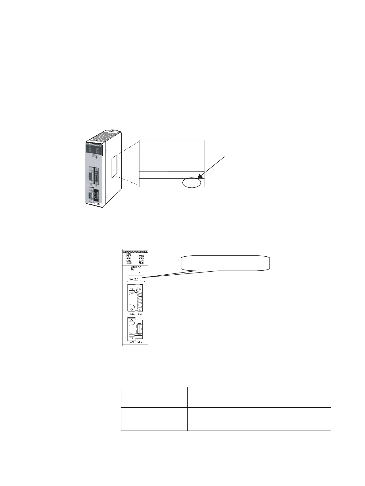
The unit version is given to the right of the lot number on the nameplate of the
applicable CS-series Advanced Motion Control Units, as shown below.
Product nameplate
OMRON CS1W-MCH71
MC UNIT
Lot No. 031001 0000 Ver.2.0
Unit version
Example for Unit version 2.0
The unit version of the Advanced Motion Control Units begins at version 2.0.
Identifying Unit Versions A unit version label is provided with the Advanced Motion Control Unit. This
label can be attached to the front of the Motion Control Unit to differentiate
between Motion Control Units of different Unit versions.
Attach the unit version label here.
Confirming Unit Versions
with Support Software
The unit version cannot be confirmed in Unit Manufacturing Information of
CX-Programmer version 4.0 or higher.
Use the MC-Miel for MCH Support Tool for Motion Control Units to confirm the
unit version, as shown in the following table.
Method for confirming the
internal system software
version
Corresponds to the unit
version
Confirm in the device information under the Tools Menu in
the MC-Miel for MCH.
Internal system software version
Pre-Ver. 2.0: 1.00xxxx to 1.04xxxx
Unit Ver. 2.0: 1.05xxxx
vii

Unit Version Notation
In this manual, the unit version of a Motion Control Unit is given as shown in
the following table.
Product nameplate Notation used in this manual Special remarks
Ver. 2.0 or later number
shown to the right of the
lot number
Blank to the right of lot
number
CS-series Advanced Motion Control Unit Ver. 2.0 or later. Information without refer-
ence to specific Unit versions applies to all versions
Pre-Ver. 2.0 CS-series Advanced Motion Control Unit
of the Unit.
Functions Supported by Advanced Motion Control Unit Ver. 2.0
Unit Version Pre-Ver. 2.0 Motion Control Unit Motion Control Unit Ver. 2.0
Internal system software version 1.00 to 1.04 1.05
CS-series Advanced Motion Control Unit
model numbers
Jogging Not supported Supported
Communications levels Not supported Supported
Communications cycle/Unit cycle Not supported Supported
LATCH command processing time Not supported Supported
Latch status refresh time Not supported Supported
Using interpolation commands during
pass operation
Acceleration/deceleration time during
pass operation
Deceleration time during pass opera-
tion
Torque to position switching Not supported Supported
Speed to position switching Not supported Supported
Support Software MC-Miel for MCH Ver. 1.5.7 or lower MC-Miel for MCH Ver. 1.5.8 or higher
CS1W-MCH71 CS1W-MCH71
Not supported Supported
Not supported Supported
Not supported Supported
Unit Versions and Lot Numbers
Type Model Date of manufacture
June 2004 or earlier July 2004 or later
CPU Bus Unit Advanced Motion Con-
trol Unit
CS1W-MCH71 No version code
(pre-Ver. 2.0)
Unit Ver. 2.0.
(Lot No.: 040715 or later)
viii

Version Upgrade Information
The following tables outline changes made for the most recent version upgrade for SYSMAC CSSeries Advanced Motion Control Units.
Jogging
Previous versions Present version (unit Ver. 2.0 or later)
The following procedure was required to set or reverse
the jogging direction.
• Specify the feed direction using the JOG/STEP Direction Bit.
• Turn ON The JOG Operation Bit.
• Turn OFF the JOG Operation Bit to reverse the feed
direction.
• Reverse the JOG/STEP Direction Bit after the axis
has stopped.
• Turn ON the JOG Operation Bit.
• The jogging direction will then be reversed.
Network Levels
Previous versions Present version (unit Ver. 2.0 or later)
Motion Control Units could be used to control communications across three network levels.
• The following setting/reversal method has been
added.
• Specify the feed direction using the JOG/STEP Direction Bit.
• Turn ON the JOG Operation Bit.
• Leave the JOG Operation Bit turned ON and simply
reverse the JOG/STEP Direction Bit setting to reverse
the feed direction.
• Use the following parameter to switch between the
previous function and the new function.
Parameter No.: P00004
Bit: 05
0: Default setting. Same functionality as previous versions. This bit was previously reserved (default setting
0).
1: Selects new function supported with this version.
Motion Control Units now support communications
across eight network levels, the same as CPU Units.
CPU Units with unit Ver. 2.0 or later support eight network levels.
Communications Cycle/Unit Cycle
Previous versions Present version (unit Ver. 2.0 or later)
The communications cycle and Unit cycle were as follows:
Communications cycle: 1 ms, 2 ms, or 4 ms
Unit cycle: 1 ms, 2 ms, 4 ms, or 8 ms
LATCH Command Processing Time
Previous versions Present version (unit Ver. 2.0 or later)
The time required to detect the external latch signal
after the LATCH command is executed was as follows:
Receiving latch signals at any position:
105 ms to 232 ms
Receiving only those latch signals within a specific
positioning range: 105 ms to 232 ms
• A 3-ms communications cycle is now supported,
enabling higher-precision performance.
Communications cycle: 1 ms, 2 ms, 3 ms, or 4 ms
Unit cycle: 1 ms, 2 ms, 3 ms, 4 ms, 6 ms, or 8 ms
• Use the following parameter to switch between the
previous function and the new function.
Parameter No.: P00004
Bit: 03
0: Default setting. Same functionality as previous versions. This bit was previously reserved (default setting
0).
1: Enables 3-ms cycle provided with this version.
The required time has been shortened for receiving
latch signals at any position, as follows:
Receiving latch signals at any position:
3 ms to 24 ms (improved)
Receiving only those latch signals within a specific
positioning range: 105 ms to 232 ms (same)
ix

Latch Status Refresh Time
Previous versions Present version (unit Ver. 2.0 or later)
After LATCH command execution, the time required
from input of the latch signal until the input is reflected
in the system variable (variable showing latch completion) was as follows:
14.5 ms to 85.5 ms
The required time has been shortened as follows:
7.5 ms to 37.5 ms
Using Interpolation Commands in Pass Operations
Previous versions Present version (unit Ver. 2.0 or later)
To execute a pass operation when the axis was
stopped required two interpolation commands just for
the first movement.
Example:
PASSMODE;
MOVEL [J01]100 F10000;
MOVEL [J02]400 F10000;
WHILE #MW0000==0;
INC MOVEL [J02]100 F1000;
WEND;
etc.
A pass operation can be executed when the axis is
stopped using a single interpolation command.
Example:
PASSMODE;
WHILE #MW0000==0;
INC MOVEL [J02]100 F1000;
WEND;
etc.
Acceleration/Deceleration Time During Pass Operation
Previous versions Present version (unit Ver. 2.0 or later)
Parallel processing had to be executed using the PARALLEL command to change the acceleration/deceleration time during a pass operation, making changes at
user-specified timing difficult.
• The acceleration/deceleration time can be changed
during pass operation.
• The acceleration/deceleration time can be easily
switched using the newly added parameter, as follows:
MOVEL [J01]1000 F1000
#IW0A00 = 2; [The pass operation will be performed
to the next position using the time set in bank 2.]
MOVEL [J01]5000 F1000
• The following ten new parameters have been added
and use the area previously allocated for task parameters.
The setting range is 0 to 60,000 ms.
No.
P00M11 Interpolation feed acceleration/deceleration time (Bank 1)
to
P00M20 Interpolation feed acceleration/deceleration
time (Bank 10)
x
Deceleration Time During Pass Operation
Previous versions Present version (unit Ver. 2.0 or later)
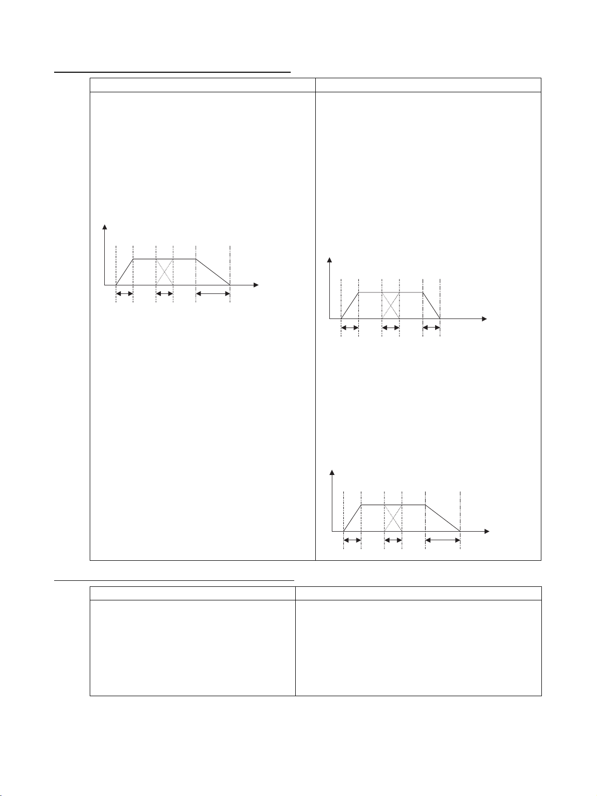
The interpolation feed deceleration time was used to
decelerate to a stop during pass operation.
Example:
Pass Mode Select P00M06 = 0
Interpolation feed acceleration time Ta=P0MM02
Interpolation feed deceleration time Td=P00M03
Program:
PASSMODE;
INC MOVEL [J01]1000 F100000;
INC MOVEL [J01]1000 F100000;
END;
Speed
Time
Ta Ta Td
• The interpolation time used for the pass operation
(interpolation feed acceleration time or deceleration
time) is used to decelerate to a stop during pass operation.
Example:
Pass Mode Select P00M06 = 0
Interpolation feed acceleration time Ta=P0MM02
Interpolation feed deceleration time Td=P00M03
Program:
PASSMODE;
INC MOVEL [J01]1000 F100000;
INC MOVEL [J01]1000 F100000;
END;
Speed
Time
Ta Ta Ta
• To decelerate to a stop using the interpolation feed
deceleration time in the same way as previous versions, add STOPMODE before the final interpolation
command before stopping.
PASSMODE;
INC MOVEL [J01]1000 F100000;
STOPMODE
INC MOVEL [J01]1000 F100000;
END;
Switching from Torque to Position Control
Previous versions Present version (unit Ver. 2.0 or later)
Torque control switched could be switched to position control using the TORQUR command only
after the axis feedback speed reached 0.
Speed
Time
Ta Ta Td
• Torque control can be switched to position control using the
TORQUR command when the axis feedback speed
reaches the speed specified in the specified parameter
(specified as a percentage of the rated speed).
• The following new parameter uses an area previously
reserved in the axis parameter area.
Parameter No.: P3AA09
Parameter name: Position Control Switching Speed
Setting range: 0 to 32767 (unit: 0.01%)
xi

Switching from Speed to Position Control
Previous versions Present version (unit Ver. 2.0 or later)
Speed control switched could be switched to position control using the SPEEDR command only
after the axis feedback speed reached 0.
• Speed control can be switched to position control using the
SPEEDR command when the axis feedback speed reaches
the speed specified in the specified parameter (specified as
a percentage of the rated speed).
• The following new parameter uses an area previously
reserved in the axis parameter area
Parameter No.: P3AA09
Parameter name: Position Control Switching Speed
Setting range: 0 to 32767 (unit: 0.01%)
xii

TABLE OF CONTENTS
PRECAUTIONS . . . . . . . . . . . . . . . . . . . . . . . . . . . . . . . . . . . xix
1 Intended Audience. . . . . . . . . . . . . . . . . . . . . . . . . . . . . . . . . . . . . . . . . . . . . . . . . . . . . . . . . xx
2 General Precautions. . . . . . . . . . . . . . . . . . . . . . . . . . . . . . . . . . . . . . . . . . . . . . . . . . . . . . . . xx
3 Safety Precautions . . . . . . . . . . . . . . . . . . . . . . . . . . . . . . . . . . . . . . . . . . . . . . . . . . . . . . . . . xxi
4 Application Precautions. . . . . . . . . . . . . . . . . . . . . . . . . . . . . . . . . . . . . . . . . . . . . . . . . . . . .xxii
5 Operating Environment Precautions . . . . . . . . . . . . . . . . . . . . . . . . . . . . . . . . . . . . . . . . . . . xxiii
6 Conformance to EC Directives . . . . . . . . . . . . . . . . . . . . . . . . . . . . . . . . . . . . . . . . . . . . . . . xxiv
SECTION 1
Features and System Configuration . . . . . . . . . . . . . . . . . . . 1
1-1 Features . . . . . . . . . . . . . . . . . . . . . . . . . . . . . . . . . . . . . . . . . . . . . . . . . . . . . . . . . . . . . . . . . 2
1-2 System Configuration . . . . . . . . . . . . . . . . . . . . . . . . . . . . . . . . . . . . . . . . . . . . . . . . . . . . . . 4
1-3 Basic Operations . . . . . . . . . . . . . . . . . . . . . . . . . . . . . . . . . . . . . . . . . . . . . . . . . . . . . . . . . . 6
1-4 Control System Configuration and Principles . . . . . . . . . . . . . . . . . . . . . . . . . . . . . . . . . . . . 10
1-5 Performance Specifications . . . . . . . . . . . . . . . . . . . . . . . . . . . . . . . . . . . . . . . . . . . . . . . . . .11
1-6 Command List . . . . . . . . . . . . . . . . . . . . . . . . . . . . . . . . . . . . . . . . . . . . . . . . . . . . . . . . . . . . 16
1-7 Performance. . . . . . . . . . . . . . . . . . . . . . . . . . . . . . . . . . . . . . . . . . . . . . . . . . . . . . . . . . . . . . 18
SECTION 2
Basic Procedures . . . . . . . . . . . . . . . . . . . . . . . . . . . . . . . . . . . 23
2-1 Basic Operation Flow . . . . . . . . . . . . . . . . . . . . . . . . . . . . . . . . . . . . . . . . . . . . . . . . . . . . . . 24
2-2 Overview and Operating Procedure of MC-Miel . . . . . . . . . . . . . . . . . . . . . . . . . . . . . . . . . 26
SECTION 3
Installation and Wiring . . . . . . . . . . . . . . . . . . . . . . . . . . . . . 29
3-1 Nomenclature and Functions. . . . . . . . . . . . . . . . . . . . . . . . . . . . . . . . . . . . . . . . . . . . . . . . . 30
3-2 Installation . . . . . . . . . . . . . . . . . . . . . . . . . . . . . . . . . . . . . . . . . . . . . . . . . . . . . . . . . . . . . . . 32
3-3 External I/O Circuitry . . . . . . . . . . . . . . . . . . . . . . . . . . . . . . . . . . . . . . . . . . . . . . . . . . . . . . 35
3-4 Wiring . . . . . . . . . . . . . . . . . . . . . . . . . . . . . . . . . . . . . . . . . . . . . . . . . . . . . . . . . . . . . . . . . . 37
3-5 Connecting MECHATROLINK Devices. . . . . . . . . . . . . . . . . . . . . . . . . . . . . . . . . . . . . . . . 38
SECTION 4
MC Unit Internal Data Configuration and Setting . . . . . . . 49
4-1 Data Configuration . . . . . . . . . . . . . . . . . . . . . . . . . . . . . . . . . . . . . . . . . . . . . . . . . . . . . . . . 50
4-2 System Parameters. . . . . . . . . . . . . . . . . . . . . . . . . . . . . . . . . . . . . . . . . . . . . . . . . . . . . . . . . 52
4-3 Variables . . . . . . . . . . . . . . . . . . . . . . . . . . . . . . . . . . . . . . . . . . . . . . . . . . . . . . . . . . . . . . . . 91
4-4 Position Data . . . . . . . . . . . . . . . . . . . . . . . . . . . . . . . . . . . . . . . . . . . . . . . . . . . . . . . . . . . . . 93
4-5 System Variables . . . . . . . . . . . . . . . . . . . . . . . . . . . . . . . . . . . . . . . . . . . . . . . . . . . . . . . . . . 96
4-6 I/O Variables . . . . . . . . . . . . . . . . . . . . . . . . . . . . . . . . . . . . . . . . . . . . . . . . . . . . . . . . . . . . . 143
4-7 Present Position Preset. . . . . . . . . . . . . . . . . . . . . . . . . . . . . . . . . . . . . . . . . . . . . . . . . . . . . . 170
4-8 Servo Parameter. . . . . . . . . . . . . . . . . . . . . . . . . . . . . . . . . . . . . . . . . . . . . . . . . . . . . . . . . . . 171
4-9 CAM Data . . . . . . . . . . . . . . . . . . . . . . . . . . . . . . . . . . . . . . . . . . . . . . . . . . . . . . . . . . . . . . . 190
xiii

TABLE OF CONTENTS
SECTION 5
Data Transfer and Storage. . . . . . . . . . . . . . . . . . . . . . . . . . . 193
5-1 Data Transfer and Storage . . . . . . . . . . . . . . . . . . . . . . . . . . . . . . . . . . . . . . . . . . . . . . . . . . .194
5-2 IOWR Instruction to Transfer Data . . . . . . . . . . . . . . . . . . . . . . . . . . . . . . . . . . . . . . . . . . . . 203
5-3 IORD Instruction to Transfer Data . . . . . . . . . . . . . . . . . . . . . . . . . . . . . . . . . . . . . . . . . . . . 210
5-4 Saving Data . . . . . . . . . . . . . . . . . . . . . . . . . . . . . . . . . . . . . . . . . . . . . . . . . . . . . . . . . . . . . . 216
SECTION 6
Programming . . . . . . . . . . . . . . . . . . . . . . . . . . . . . . . . . . . . . 219
6-1 Program and Task Configuration . . . . . . . . . . . . . . . . . . . . . . . . . . . . . . . . . . . . . . . . . . . . . . 220
6-2 Command Overview . . . . . . . . . . . . . . . . . . . . . . . . . . . . . . . . . . . . . . . . . . . . . . . . . . . . . . .260
6-3 Command Details . . . . . . . . . . . . . . . . . . . . . . . . . . . . . . . . . . . . . . . . . . . . . . . . . . . . . . . . . 271
SECTION 7
PC Interface Area . . . . . . . . . . . . . . . . . . . . . . . . . . . . . . . . . . 339
7-1 Overview . . . . . . . . . . . . . . . . . . . . . . . . . . . . . . . . . . . . . . . . . . . . . . . . . . . . . . . . . . . . . . . . 340
7-2 Operating Mode. . . . . . . . . . . . . . . . . . . . . . . . . . . . . . . . . . . . . . . . . . . . . . . . . . . . . . . . . . . 345
7-3 Allocations for the CPU Unit . . . . . . . . . . . . . . . . . . . . . . . . . . . . . . . . . . . . . . . . . . . . . . . . 358
7-4 Interface Specifics . . . . . . . . . . . . . . . . . . . . . . . . . . . . . . . . . . . . . . . . . . . . . . . . . . . . . . . . . 381
SECTION 8
Establishing the Origin. . . . . . . . . . . . . . . . . . . . . . . . . . . . . . 489
8-1 Overview . . . . . . . . . . . . . . . . . . . . . . . . . . . . . . . . . . . . . . . . . . . . . . . . . . . . . . . . . . . . . . . . 490
8-2 Input Signals Required for Origin search . . . . . . . . . . . . . . . . . . . . . . . . . . . . . . . . . . . . . . . 492
8-3 Origin Search Methods and Parameters . . . . . . . . . . . . . . . . . . . . . . . . . . . . . . . . . . . . . . . . 492
8-4 Origin Search Operations . . . . . . . . . . . . . . . . . . . . . . . . . . . . . . . . . . . . . . . . . . . . . . . . . . .494
8-5 Absolute (ABS) Encoders . . . . . . . . . . . . . . . . . . . . . . . . . . . . . . . . . . . . . . . . . . . . . . . . . . .497
8-6 ABS Encoder Origin Setting . . . . . . . . . . . . . . . . . . . . . . . . . . . . . . . . . . . . . . . . . . . . . . . . . 498
SECTION 9
Other Operations . . . . . . . . . . . . . . . . . . . . . . . . . . . . . . . . . . 503
9-1 Teaching. . . . . . . . . . . . . . . . . . . . . . . . . . . . . . . . . . . . . . . . . . . . . . . . . . . . . . . . . . . . . . . . . 504
9-2 Debugging the Program. . . . . . . . . . . . . . . . . . . . . . . . . . . . . . . . . . . . . . . . . . . . . . . . . . . . .510
9-3 Coordinate System. . . . . . . . . . . . . . . . . . . . . . . . . . . . . . . . . . . . . . . . . . . . . . . . . . . . . . . . . 514
9-4 Backup and Restore Function . . . . . . . . . . . . . . . . . . . . . . . . . . . . . . . . . . . . . . . . . . . . . . . . 522
SECTION 10
Program Example . . . . . . . . . . . . . . . . . . . . . . . . . . . . . . . . . . 525
10-1 Program Example . . . . . . . . . . . . . . . . . . . . . . . . . . . . . . . . . . . . . . . . . . . . . . . . . . . . . . . . . 526
10-2 Slave Modules . . . . . . . . . . . . . . . . . . . . . . . . . . . . . . . . . . . . . . . . . . . . . . . . . . . . . . . . . . . . 560
10-3 Others. . . . . . . . . . . . . . . . . . . . . . . . . . . . . . . . . . . . . . . . . . . . . . . . . . . . . . . . . . . . . . . . . . . 572
xiv

TABLE OF CONTENTS
SECTION 11
Troubleshooting . . . . . . . . . . . . . . . . . . . . . . . . . . . . . . . . . . . 581
11-1 Troubleshooting. . . . . . . . . . . . . . . . . . . . . . . . . . . . . . . . . . . . . . . . . . . . . . . . . . . . . . . . . . . 582
11-2 Countermeasures . . . . . . . . . . . . . . . . . . . . . . . . . . . . . . . . . . . . . . . . . . . . . . . . . . . . . . . . . . 588
11-3 Error Indicators . . . . . . . . . . . . . . . . . . . . . . . . . . . . . . . . . . . . . . . . . . . . . . . . . . . . . . . . . . . 592
11-4 Unit-related Alarm Codes . . . . . . . . . . . . . . . . . . . . . . . . . . . . . . . . . . . . . . . . . . . . . . . . . . . 593
11-5 Motion Task-related Alarm Codes. . . . . . . . . . . . . . . . . . . . . . . . . . . . . . . . . . . . . . . . . . . . . 596
11-6 Axis-related Alarm Codes . . . . . . . . . . . . . . . . . . . . . . . . . . . . . . . . . . . . . . . . . . . . . . . . . . .602
11-7 MLK Device Alarm Codes . . . . . . . . . . . . . . . . . . . . . . . . . . . . . . . . . . . . . . . . . . . . . . . . . . 607
11-8 Servo Driver Warnings. . . . . . . . . . . . . . . . . . . . . . . . . . . . . . . . . . . . . . . . . . . . . . . . . . . . . . 609
11-9 Error Log . . . . . . . . . . . . . . . . . . . . . . . . . . . . . . . . . . . . . . . . . . . . . . . . . . . . . . . . . . . . . . . . 610
SECTION 12
Maintenance and Inspection . . . . . . . . . . . . . . . . . . . . . . . . . 613
12-1 Routine Inspection . . . . . . . . . . . . . . . . . . . . . . . . . . . . . . . . . . . . . . . . . . . . . . . . . . . . . . . . . 614
Revision History . . . . . . . . . . . . . . . . . . . . . . . . . . . . . . . . . . . 617
xv

TABLE OF CONTENTS
xvi

About this Manual:
This manual describes the installation and operation of the CS1W-MCH71 Motion Control Unit (MC
Unit) and includes the sections described below.
Please read this manual carefully and be sure you understand the information provided before
attempting to install or operate the MC Unit. Be sure to read the precautions provided in the following
section.
Precautions provides general precautions for using the Motion Control Unit, Programmable Controller,
and related devices.
Section 1 introduces the features and system configuration of the CS1W-MCH71 CS-series Motion
Control Unit. It also describes product operating principles and provides product specifications
Section 2 provides an overview of the basic procedures required to use the CS1W-MCH71 Motion
Control Unit.
Section 3 describes the names of Unit parts and how to install and wire the CS1W-MCH71 Motion
Control Unit.
Section 4 describes the data configuration uses to set up, operate, and monitor the CS1W-MCH71
Motion Control Unit and related devices.
Section 5 describes how to transfer data between the CPU Unit and the CS1W-MCH71 Motion Control Unit and how data is stored.
Section 6 describes how to program CS1W-MCH71 Motion Control Unit operation, including the program configuration and the specific commands used in programming.
Section 7 describes the interface area in the CPU Unit used to control and monitor the CS1W-MCH71
Motion Control Unit.
Section 8 describes how to establish the origin in the positioning system.
Section 9 describes special operations for the CS1W-MCH71 Motion Control Unit, including teaching,
program debugging, coordinate systems, and backup functions.
Section 10 provides a programming example to demonstrate how the CS1W-MCH71 Motion Control
Unit can be used.
Section 11 describes how to troubleshoot problems that may occur when using the CS1W-MCH71
Motion Control Unit.
Section 12 describes the maintenance and inspection procedures required to keep the CS1W-MCH71
Motion Control Unit in optimum condition.
!WARNING Failure to read and understand the information provided in this manual may result in per-
sonal injury or death, damage to the product, or product failure. Please read each section
in its entirety and be sure you understand the information provided in the section and
related sections before attempting any of the procedures or operations given.
xvii

xviii

PRECAUTIONS
This section provides general precautions for using the CS1W-MCH71 Motion Control Unit and related devices.
The information contained in this section is important for the safe and reliable application of the CS1W-MCH71
Motion Control Unit. You must read this section and understand the information contained before attempting to set
up or operate a CS1W-MCH71 Motion Control Unit.
1 Intended Audience . . . . . . . . . . . . . . . . . . . . . . . . . . . . . . . . . . . . . . . . . . . . . xx
2 General Precautions . . . . . . . . . . . . . . . . . . . . . . . . . . . . . . . . . . . . . . . . . . . . xx
3 Safety Precautions. . . . . . . . . . . . . . . . . . . . . . . . . . . . . . . . . . . . . . . . . . . . . . xxi
4 Application Precautions . . . . . . . . . . . . . . . . . . . . . . . . . . . . . . . . . . . . . . . . . xxii
5 Operating Environment Precautions . . . . . . . . . . . . . . . . . . . . . . . . . . . . . . . . xxiii
6 Conformance to EC Directives . . . . . . . . . . . . . . . . . . . . . . . . . . . . . . . . . . . . xxiv
6-1 Applicable Directives . . . . . . . . . . . . . . . . . . . . . . . . . . . . . . . . . . . . xxiv
6-2 Concepts . . . . . . . . . . . . . . . . . . . . . . . . . . . . . . . . . . . . . . . . . . . . . . xxiv
6-3 Conformance to EC Directives . . . . . . . . . . . . . . . . . . . . . . . . . . . . . xxiv
6-4 Installation within Control Panel . . . . . . . . . . . . . . . . . . . . . . . . . . . xxiv
xix

Intended Audience 1
1 Intended Audience
This manual is intended for the following personnel, who must also have
knowledge of electrical systems (an electrical engineer or the equivalent).
• Personnel in charge of installing FA systems.
• Personnel in charge of designing FA systems.
• Personnel in charge of managing FA systems and facilities.
2 General Precautions
The user must operate the product according to the performance specifications described in the operation manuals.
Before using the product under conditions which are not described in the
manual or applying the product to nuclear control systems, railroad systems,
aviation systems, vehicles, combustion systems, medical equipment, amusement machines, safety equipment, and other systems, machines, and equipment that may have a serious influence on lives and property if used
improperly, consult your OMRON representative.
Make sure that the ratings and performance characteristics of the product are
sufficient for the systems, machines, and equipment, and be sure to provide
the systems, machines, and equipment with double safety mechanisms.
This manual provides information for programming and operating the Unit. Be
sure to read this manual before attempting to use the Unit and keep this manual close at hand for reference during operation.
!WARNING It is extremely important that a PLC and all PLC Units be used for the speci-
fied purpose and under the specified conditions, especially in applications that
can directly or indirectly affect human life. You must consult with your OMRON
representative before applying a PLC System to the above-mentioned applications.
xx
Safety Precautions 3
3 Safety Precautions
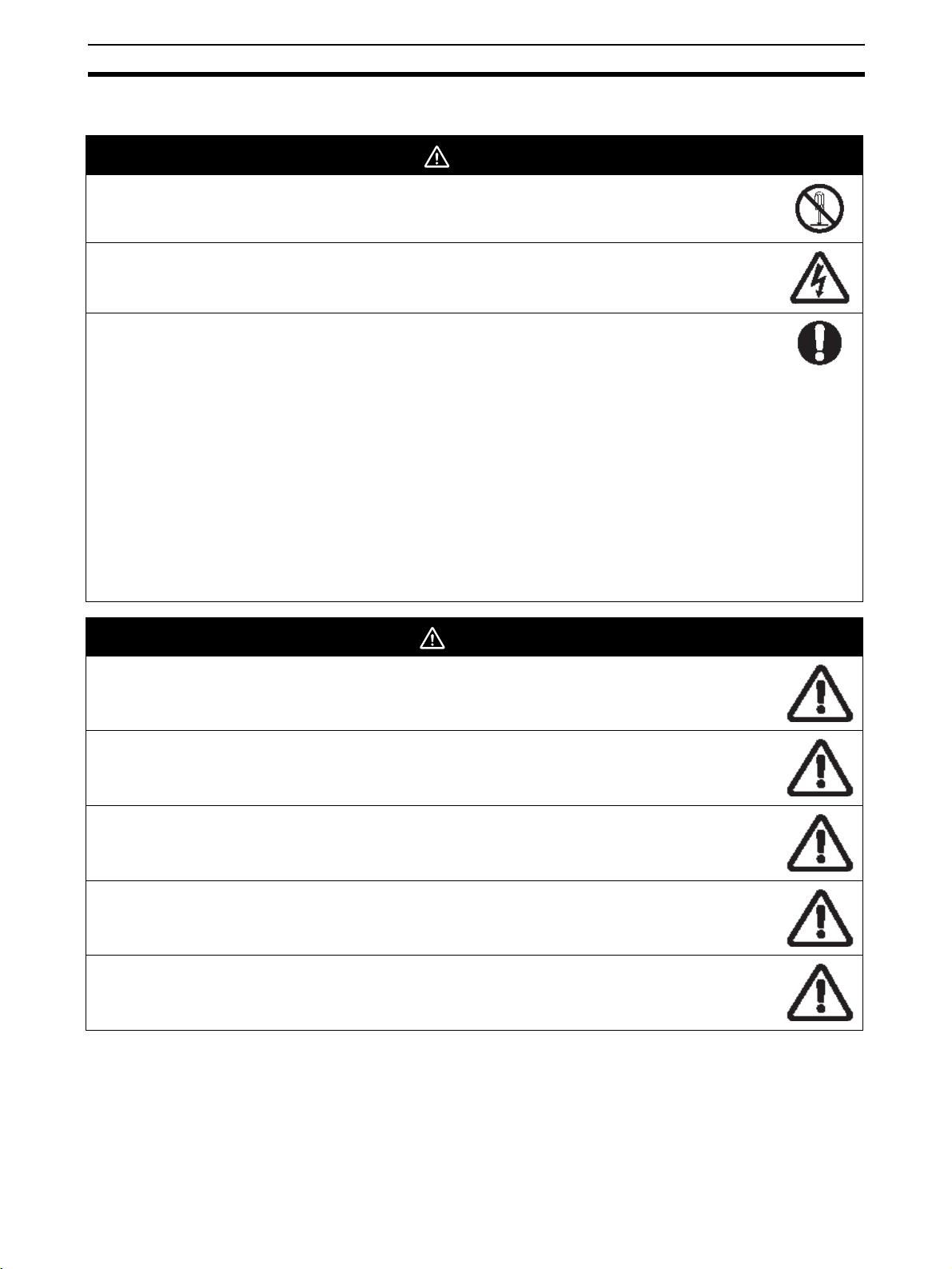
DANGER
Never attempt to disassemble any Units while power is being supplied.
Doing so may result in serious electronic shock.
Never touch any of the terminals while power is being supplied.
Doing so may result in serious electronic shock.
Provide safety measures in external circuits (i.e., not in the Programmable Controller or MC Unit) to ensure
safety in the system if an abnormality occurs due to malfunction of the PLC or MC unit. Not providing sufficient safety measures may result in serious accidents.
• Emergency- stop circuits, interlock circuits, limit circuits, and similar safety measures must be provided in external control circuits.
• The PLC will turn OFF all outputs when its self-diagnosis function detects any error or when a severe failure alarm
(FALS) instruction is executed. As a countermeasure for such errors, external safety measures must be provided to
ensure safety in the system.
• The PLC or MC Unit outputs may remain ON or OFF due to deposits on or burning of the output relays, or destruction of
the output transistors. As a countermeasure for such problems, external safety measures must be provided to ensure
safety in the system.
• When the 24-VDC (service power supply to the PLC) is overloaded or short-circuited, the voltage may drop result in the
outputs being turned OFF. As a countermeasure for such problems, external safety measures must be provided to
ensure safety in the system.
• Provide safety measures in external circuits to ensure safety in system if an abnormality occurs due to malfunction of MC
Unit connectors.
WARNING
Execute online edit only after confirming that the cycle time extension will not cause any adverse effects.
Some input signals may not be read if the cycle time is extended.
Confirm the safety of the destination node before transferring program to the node or changing the contents
of I/O memory. Doing either of these without confirming safety may result in injury.
Do not save data into the flash memory during memory operation or while the motor is running. Otherwise,
unexpected operation may be caused.
Do not reverse the polarity of the 24-V power supply. The polarity
Must be correct. Otherwise, the motor may start running unexpectedly and may not stop.
When positioning is performed using Teaching function, positioning specification in the motion program must
be [Absolute specification].
If [Incremental specification] is specified, positioning will be executed at the different point from where
Teaching conducted.
xxi

Application Precautions 4
4 Application Precautions
Observe the following precautions when using the MC Unit or the PLC.
• Install external breakers and take other safety measures against short-circuiting in external wiring.
Insufficient safety measures against short-circuiting may result in burning.
• Always turn off after power supply to the Unit before attempting any of the following. Not turning OFF
the power supply may result in malfunction or electric shock.
• Mounting or dismounting the MC Unit or any other unit.
• Assembling the Units.
• Setting Rotary switches.
• Connecting Cables or wiring the system.
• Connecting or disconnecting the connectors.
• Confirming that no adverse effect will occur in the system before attempting any of the following. Not
doing so may result in an unexpected operation.
• Changing the operation mode of the PLC (including the setting of the startup operating mode).
• Changing the present value of any word or any set value in memory.
• Force-setting /force-resetting any bit in memory.
• Always connect to a ground of 100
of100
Ω or less may result in electric shock.
• Before touching the Unit, be sure to first touch a grounded metallic object in order to discharge any
static built-up. Not doing so may result in malfunction or damage.
• Be sure that all the mounting screws, terminal screws, and cable connector screws are tightened to
the torque specified in this manual. Incorrect tightening torque may result in malfunction.
• Tighten the mounting screws at the bottom of the Unit to a torque of 0.4 N·m.
Incorrect tightening torque may result in malfunction.
• Perform wiring according to specified procedures.
• Leave the label attached to the Unit when wiring. Removing the label may result in malfunction if foreign matter enters the Unit.
• Remove the label after the completion of wiring to ensure proper heat dissipation. Leaving the label
attached may result in malfunction.
• Check the pin numbers before wiring the connectors.
• Use crimp terminals for wiring. Do not connect bare stranded wires directly to terminals. Connection
of bare stranded wires may result in burning.
• Be sure that the connectors, terminal blocks, I/O cables, cables between drivers, and other items with
locking devices are properly locked into place. Improper locking may result in malfunction.
• Always use the power supply voltage specified in this manual. An incorrect voltage may result in malfunction or burning.
• Take appropriate measures to ensure that the specified power with the rated voltage and frequency
is supplied. Be particularly careful in places where the power supply is unstable. An in correct power
supply may result in malfunction.
• Do not apply voltages to the Input Units in excess of the rated input voltage. Excess voltage may
result in burning.
• Do not apply voltages or connect loads to the Output Units in excess of the maximum switching
capacity. Excess voltages or loads may result in burning.
• Check carefully all wiring and switch setting before turning ON the power supply. Incorrect wiring may
result in burning.
• Separate the line ground terminal (LG) from the functional ground terminal (GR) on the Power Supply
Unit before performing withstand voltage tests or insulation resistance tests. Not doing so may result
in burning.
• Do not place objects on the top of the cables or other wiring lines.
Doing either of these may break the cables.
Ω or less when installing the Units. Not connecting to a ground
xxii

Operating Environment Precautions 5
• Do not pull on the cables or bend the cables beyond their natural limit. Doing so may break the
cables.
• Do not turn off the power supply to the Unit while data is being written to flash memory.
Doing so may cause problems with flash memory.
• Confirm that user program for proper execution before actually running it on the Unit.
Not checking the program may result in an unexpected operation.
• Check the user program for proper execution before actually running it on the Unit.
Not checking the program may result in an unexpected operation.
• Resume operation only after transferring to the new MC Unit the contents of the parameters, position
data, and other data required for resuming operation.
Not doing so may result in an unexpected operation.
• Resume operation only after transferring to the new CPU Unit the contents of the DM Area, HR Area,
and other data required for resuming operation. Not doing so may result in an unexpected operation.
• After transferring the system parameters, servo parameters, programs, position data, and CAM data
to the MC Unit, be sure to save the data in flash memory within the MC Unit (using the data save
command from support tool or CPU Unit) before turning OFF the power supply to the Unit. Transferring the data to the MC Unit will simply save the data in the internal memory (S-RAM) of the MC Unit
and this data will be deleted when the power supply to the Unit is turned OFF.
• After transferring the system parameter data to the MC Unit and saving the data to flash memory, be
sure to reset the power supply to the unit or restart the Unit. Otherwise, some of the unit parameters
and machine parameters will not be changed.
• The Machine lock function is enabled in each axis, for the effects on the operations with multiple axes
such as interpolation operation be sure to machine lock all of relative axes in order to prevent the
interference with other axes or devices.
• If axes are stopped during a synchronized operation, however, the synchronization of the master axis
and slave axes positions will be cancelled. For that reason, be aware of the interference with other
axes or devices when restarting up.
• When the load OFF status is occurred in the CPU Unit during manual operation such as JOG, which
is performed by operating input variables from the MC Unit's program, the operation will be continued
for one-cycle of the Unit. Using the WHILE command to repeat until given condition is satisfied, however, it continues to operate even load-OFF has occurred, be aware of the interference with other
axes or devices.
• Parameters and programs for MC Units with unit version 2.0 or later can be transferred to pre-Ver. 2.0
MC Units, but the new and upgraded functions for unit Ver. 2.0 will be disabled.
• Do not attempt to take any Units apart, to repair any Units, or to modify any Units in anyway.
5 Operating Environment Precautions
• The installation must be conducted correctly.
• Do not operate the control system in the following places.
• Locations subject to direct sunlight
• Locations subject to temperatures or humidity outside the range specified in the specifications
• Locations subject to condensation as the result of severe changes in temperature.
• Locations subject to corrosive or flammable gases.
• Locations subject to dust (especially iron dust) or salts.
• Locations subject to exposure to water, oil, or chemicals.
• Locations subject to shock or vibration.
• Take appropriate and sufficient countermeasures when installing systems in the following locations.
Inappropriate and insufficient measures may result in malfunction.
• Locations subject to static electricity or other sources of noise.
• Locations subject to strong electromagnetic fields.
• Locations subject to possible exposure to radioactivity.
• Locations close to power supplies.
xxiii

Conformance to EC Directives 6
6 Conformance to EC Directives
6-1 Applicable Directives
EMC Directives
6-2 Concepts
EMC Directives
OMRON devices that comply with EC Directives also conform to the related EMC standards to that
they can be more easily built into other devices or machines. The actual products have been checked
for conformity to EMC standards (see the following note). The customer, however, must check whether
the products conform to the standard in the system used by the customer.
EMC related performance of the OMRON devices that comply with EC Directives would vary depending on the configuration, wiring, and other conditions of the equipment or control panel in which the
OMRON devices are installed.
The customer must, therefore, perform final checks to confirm that devices and the overall machine
conform to EMC standards.
Note Applicable EMC (Electro-Magnetic Compatibility) standards are as follows:
EMS (Electro-Magnetic Susceptibility): EN61000-6-2,
EMI (Electro-Magnetic Interference): EN55011
EN55011 Radiated emission 10-m regulations
6-3 Conformance to EC Directives
The CS1W-MCH71 “MC Unit” comply with EC Directives. To ensure that the machine or device in
which an MC Unit is used complies with EC Directives, the MC Unit must be installed as directed
below:
1. The MC Unit must be installed within a control panel.
Use a control panel like SA20-712 (Nitto Electronics) or similar to this.
2. Reinforced insulation or double insulation must be used for the DC power supplies used for the
communications and I/O power supplies.
3. MC Units complying with EC Directives also conform to the Common Emission Standard
(EN50081-2). With regard to the radiated emission (10-m regulations), countermeasures will vary
depending on the devices connected to the control panel, wiring, the configuration of the system,
and other conditions. The customer must, therefore, perform final checks to confirm that devices
and the overall machine conform to EC Directions.
6-4 Installation within Control Panel
Unnecessary clearance in cable inlet or outlet ports, operation panel mounting holes, or in the control
panel door may cause electromagnetic wave leakage or interference. In this case, the product may fail
to meet EC Directives. In order to prevent such interference, fill clearances in the control panel with
conductive packing. (In places where conductive packing comes in contact with the control panel,
ensure electrical conductivity by removing the paint coating or masking these parts when painting.)
xxiv

SECTION 1
Features and System Configuration
The section introduces the features and system configuration of the CS1W-MCH71 CS-series Motion Control Unit. It also
describes product operating principles and provides product specifications.
1-1 Features . . . . . . . . . . . . . . . . . . . . . . . . . . . . . . . . . . . . . . . . . . . . . . . . . . . . . . 2
1-1-1 Overview. . . . . . . . . . . . . . . . . . . . . . . . . . . . . . . . . . . . . . . . . . . . . . 2
1-1-2 Features. . . . . . . . . . . . . . . . . . . . . . . . . . . . . . . . . . . . . . . . . . . . . . . 3
1-2 System Configuration . . . . . . . . . . . . . . . . . . . . . . . . . . . . . . . . . . . . . . . . . . . 4
1-2-1 System Configuration Example . . . . . . . . . . . . . . . . . . . . . . . . . . . . 4
1-2-2 Peripheral Devices (Models and Specifications) . . . . . . . . . . . . . . . 5
1-3 Basic Operations . . . . . . . . . . . . . . . . . . . . . . . . . . . . . . . . . . . . . . . . . . . . . . . 6
1-3-1 Applicable Machines . . . . . . . . . . . . . . . . . . . . . . . . . . . . . . . . . . . . 6
1-3-2 Position Control . . . . . . . . . . . . . . . . . . . . . . . . . . . . . . . . . . . . . . . . 6
1-3-3 Speed Control . . . . . . . . . . . . . . . . . . . . . . . . . . . . . . . . . . . . . . . . . . 8
1-3-4 Torque Control . . . . . . . . . . . . . . . . . . . . . . . . . . . . . . . . . . . . . . . . . 8
1-3-5 Synchronous Control . . . . . . . . . . . . . . . . . . . . . . . . . . . . . . . . . . . . 8
1-3-6 Other Functions . . . . . . . . . . . . . . . . . . . . . . . . . . . . . . . . . . . . . . . . 10
1-4 Control System Configuration and Principles. . . . . . . . . . . . . . . . . . . . . . . . . 10
1-4-1 Control System Configuration . . . . . . . . . . . . . . . . . . . . . . . . . . . . . 10
1-4-2 Control System Principles . . . . . . . . . . . . . . . . . . . . . . . . . . . . . . . . 11
1-4-3 Feedback Pulse . . . . . . . . . . . . . . . . . . . . . . . . . . . . . . . . . . . . . . . . . 11
1-5 Performance Specifications. . . . . . . . . . . . . . . . . . . . . . . . . . . . . . . . . . . . . . . 11
1-5-1 General Specifications . . . . . . . . . . . . . . . . . . . . . . . . . . . . . . . . . . . 11
1-5-2 Functions and Performance Specifications. . . . . . . . . . . . . . . . . . . . 12
1-6 Command List. . . . . . . . . . . . . . . . . . . . . . . . . . . . . . . . . . . . . . . . . . . . . . . . . 16
1-7 Performance . . . . . . . . . . . . . . . . . . . . . . . . . . . . . . . . . . . . . . . . . . . . . . . . . . 18
1

Fe at ur e s Section 1-1
1-1 Features
1-1-1 Overview
The CS1W-MCH71 model is a CS-series Motion Control Unit that can control
thirty axes. An internal motion language programming is mounted, so that it
can perform the advanced motion control operations.
1. Position Control
• Point-to-Point Control: With point-to-point (PTP) control, positioning is
controlled independently for each axis. The pathway varies according to the travel distances, the
feed rates, and so on.
• Continuous Path Control:With continuous path (CP) control, not only the
start position and target position are controlled
but also the path between those points. Functions such as linear interpolation, circular interpolation, helical circular interpolation, and
traverse can be performed.
2. Speed Control
It makes the motor run at the specified speed, it also specifies the rate of
speed change.
3. Torque Control
It generates specified Torque and specifies the rate of Torque change.
4. Synchronous Control
• Electronic Shaft: Functions the same as for the rolls connected to the
gearbox with a gearshift.
• Electronic Cam: Functions the same as for the Machine CAM.
The MC Unit has been developed for use in simple positioning applications
using servomotors. Applicable machines are as follows:
• Conveyor Systems: X/Y tables, palletizers/depalletizers, loaders/unload-
ers, etc. (Palletizers and depalletizers are devices
used for loading goods onto pallets or for unloading
them from pallets. Loaders and unloaders are
devices that have shelves corresponding with the
steps of a multi-step press and used for inserting or
removing all the materials at one time.)
• Assembling Systems: Simple robots (including orthogonal robots), simple
automated assembling machines (such as coil
winding, polishing, hole punching), etc.
Note The MC Unit is not designed to perform the interpolation movement like a lin-
ear interpolation, a circular interpolation, or a helical circular interpolation with
horizontal articulated robots or cylindrical robots, because it does not support
coordinate conversions (cylindrical coordinate rotation function). The MC Unit
can, however, perform PTP control with these robots.
2

Fe at ur e s Section 1-1
1-1-2 Features
Simple System
Architecture
Easiest Information
Management
Various motion controls
~Distributed control
system~
High-speed and flexibility • It is possible to realize variety of applications because of its availability for
• Independent control of multiple axes (Up to 30 physical axes; including
virtual axes total is 32)
• Each axis can be set as either a physical or virtual axis.
• Additional unit is not required.
• High-speed channel with servo driver enables parameters' setting of
servo driver, status monitoring.
These functions are possible from computer support tool or PT.
• Backup using Memory Card in CPU Unit.
• Besides CPU Unit of PLC, executes motion program for motion control.
• Regarding to motion task, up to 8 motion programs can be simultaneously
executed. In each of these 8 programs, programs can be executed in parallel.
Synchronous Controls (Electric Shaft, Electronic cam, Trailing Synchronization), Speed Control, Torque Control, and Position Control.
• The minimum length of servo communication cycle is 1 ms.
• It is possible to switch position, speed, and Torque command during axis
movement (there are few restrictions).
• The accurate controls of MC Unit and Servo driver or dispersion module
are possible conducting a completely synchronized processing at fixed
intervals.
Combination of basic
functions makes variety of
synchronizations possible
• Electronic Shaft function
• Electronic cam function (Time, position)
• Virtual axis function
• Axis movement function for superimposed axis, ADDAX
• Resist function (with present position hardware latch and window func-
tion).
• Electronic link operation
• Trailing synchronization
• Target position change function
• Speed command
• Torque command
• Time-fixed positioning
3
System Configuration Section 1-2
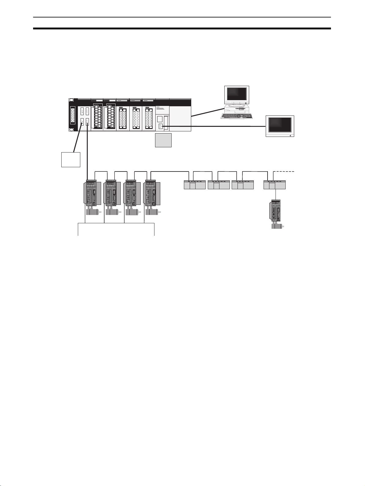
1-2 System Configuration
1-2-1 System Configuration Example
The MC Unit is adopted a high-speed communication pathway to simplify its
wiring. It makes it possible to have up to 30 axes for controls.
Sensor/
Valve
MCH71
CW Limit/CCW Limit
Computer
Memory
W-series Servo
+
I/F unit
card
Max.30 axes (nodes)/total length 50 m
CounterDI/O DI/O Pulse output
PT
Stepping
Note (1) The MECHATROLINK is registered trademark of YASKAWA ELECTRIC
CORPORATION.
(2) W-series servo driver requires YASKAWA MECHATROLINK-II I/F unit
model JUSP-NS115.
(3) Each of the products of the following version can be used. The version
name is identified on the nameplates of each product.
W-series servo driver: VER.39 or Later
I/F unit: VER ***03 Later, or Equal
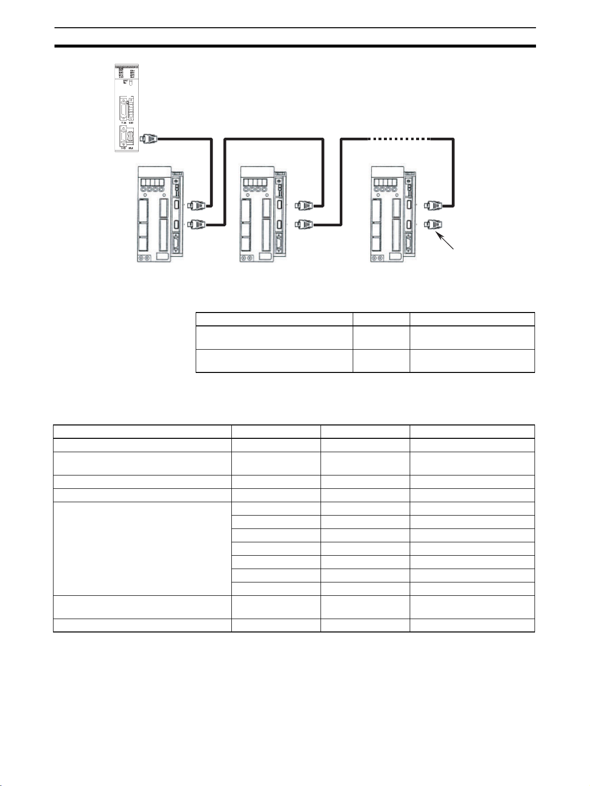
(4) When MECHATROLINK-II devices are connected up to 16 nodes (within
30 m) or 15 nodes (within 50 m), a repeater unit is not required. A repeater unit is required to connect MECHATROLINK-II devices more than the
cases above.
(5) Attach a terminator to the termination slave of MECHATROLINK devices.
4
System Configuration Section 1-2
r
Terminato
1-2-2 Peripheral Devices (Models and Specifications)
Support Tool
Name Cat. No. Specification Overview
Support Tool for Motion Control Unit
MC-Miel for MCH
Support Tool for Motion Control Unit
MC-Miel for MCH
SBCE-023B Support Tool for computers
Japanese version
I809-E1-02 Support tool for computers
English version
Note When ordering support tools, please contact our sales representatives indi-
cating the Cat. No.
MECHATROLINK-II Devices and Cables
Name YASKAWA Model OMRON Model Specification Overview
MECHATROLINK-II I/F Unit JUSP-NS115 FNY-NS115 For W-series servo driver
DC24V I/O Module JEPMC-IO2310 FNY-IO2310 Input: 64
Counter Module JEPMC-PL2900 FNY-PL2900 Reversing Counter 2CH
Pulse Output module JEPMC-PL2910 FNY-PL2910 Pulse Positioning
MECHATROLINK-II Cables for W-Series
(With USB connectors and Ring Core)
Terminating resistance for MECHATROLINK-II
Repeater for MECHATROLINK-II JEPMC-REP2000 FNY-REP2000 Repeater
JEPMC-W6003-A5 FNY-W6003-A5 0.5 m
JEPMC-W6003-01 FNY-W6003-01 1.0 m
JEPMC-W6003-03 FNY-W6003-03 3.0 m
JEPMC-W6003-05 FNY-W6003-05 5.0 m
JEPMC-W6003-10 FNY-W6003-10 10.0 m
JEPMC-W6003-20 FNY-W6003-20 20.0 m
JEPMC-W6003-30 FNY-W6003-30 30.0 m
JEPMC-W6022 FNY-W6022 Terminating resistance
Output: 64
Note MECHATROLINK-related products are manufactured by YASKAWA ELEC-
TRIC CORPORATION.
We, OMRON, can take orders for them. When ordering them through
OMRON, follow OMRON's ordering format. (The delivered products will be of
YASKAWA BRAND.)
Ask our sales representatives about the price at when ordering them through
OMRON.
5
Basic Operations Section 1-3
1-3 Basic Operations
1-3-1 Applicable Machines
The MC Unit was developed for the purpose of motion control using servomotors.
Even though it depends on the machine accuracy, use an encoder, which is
capable to detect 5-10 times more accurate than the machine accuracy.
Applicable machines
1,2,3... 1. Assembling Systems
Simple robots, package machinery (horizontal type forming and vertical
type forming), filling machine, grinder, drilling machinery, simple automated assembling machines, etc.
2. Conveyor Systems
XY tables, palletizers/depalletizers, loaders/unloaders, etc.
Note The MC Unit is not designed to perform linear interpolation, circular interpola-
tion, or helical circular interpolation with horizontal articulated robots or cylindrical robots, because it does not support coordinate conversions. The MC
Unit can, however, perform PTP control with these robots.
1-3-2 Position Control
The MC Unit offers the following three types of motion control:
•PTP Control
• CP Control (linear interpolation and circular interpolation)
• Interrupt Feeding
Control programs are created in the Motion language.
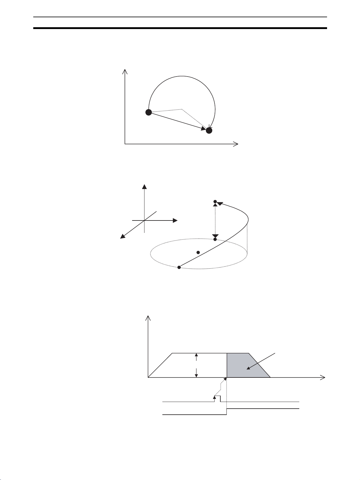
PTP Control PTP control is used to control each axis (J01 and J02 axis) independently.
Positioning time depends on the travel distance and speed of each axis.
Example: Moving from the origin to the J01-axis coordinate of 100 and J02-
axis coordinate of 50 at the same speed.
Positioning is executed separately for each axis, so travel between the two
points is carried out as shown in the diagram below:
J02
50
J01
0 50 100
6
Basic Operations Section 1-3
J
CP Control CP Control is used to position by designing not only the starting point and the
target point, but also the path between these two points. Both linear interpolation and circular interpolation are possible.
02
Circular interpolation
Center
Starting
point
Linear interpolation
If [axis name 3] is added, helical interpolation is added to the linear interpolation. (The linear interpolation portion for multiple revolutions specifies the total
travel distance.)
Axis 3
Radius
Target point
J01
Target point
Linear
Axis 1
Axis 2
Center
Starting point
interpolation
Circular interpolation
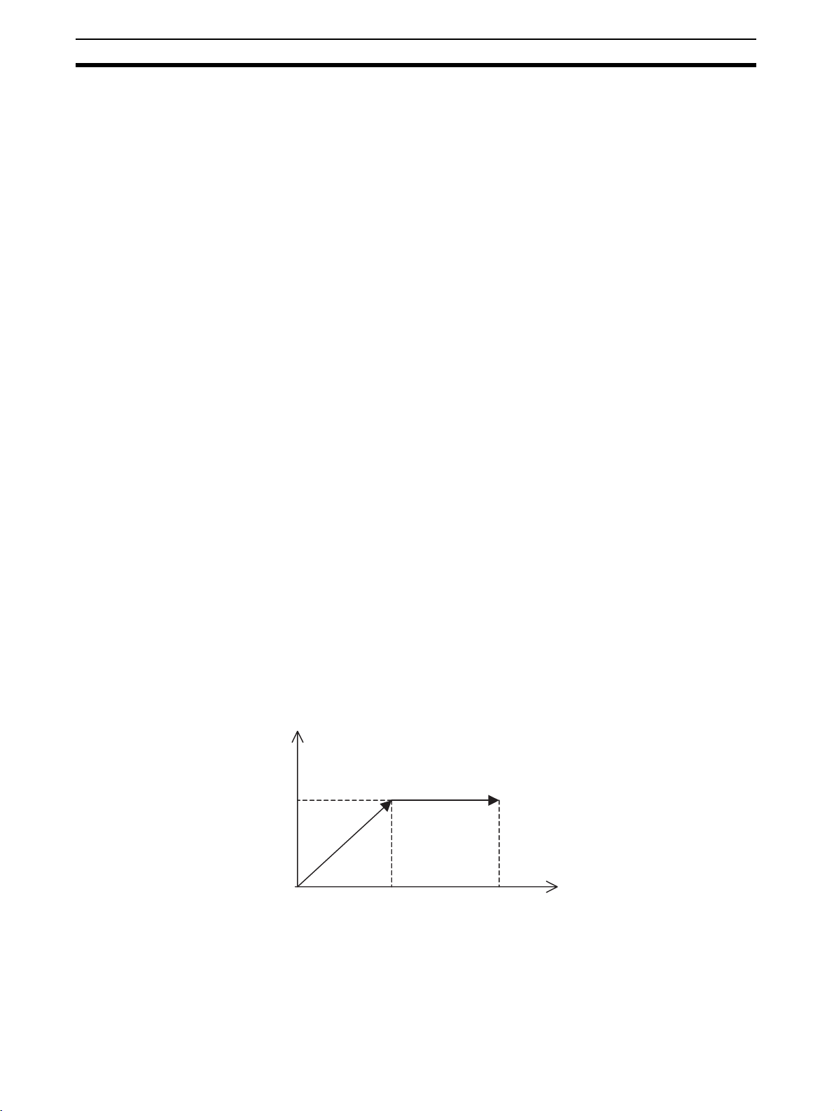
Interrupt Feeding Interrupt feeding is used to perform position control for a fixed distance when
the external signal is input.
Positioning with no interrupt signal is also possible.
Speed
Position control
(Fixed distance)
Speed
t
External signal
Counter latch completed
7

Basic Operations Section 1-3
1-3-3 Speed Control
Make the motor run at a specified speed. It is also possible to specify the
speed change rate.
Speed
Speed change rate
Speed command value
t
1-3-4 Torque Control
The designated torque can be generated. It is also possible to specify the
torque change rate.
Torque
Torque change rate
Torque command value
1-3-5 Synchronous Control
Listed below are the synchronous controls of this unit.
• Electronic Shaft
• Electronic cam
• Linking motions
• Trailing synchronization
• Super position control
Each of above controls is programmed by motion language.
Electronic Shaft This function can be used like rolls connected to gearbox with gearshift.
The slave axis synchronizes with the master axis at a specified ratio.
Electronic cam This function can be used like the cam mechanism of a machine.
The slave axis synchronizes with the master axis according to the cam table.
t
8

Basic Operations Section 1-3
Link operation This function can be used like the link mechanism of a machine.
The slave axis synchronizes with the master axis following the specified acceleration, constant speed, and deceleration areas.
(In the diagram below, vertical and horizontal axes indicate speed and time
respectively.)
Acceleration Constant speed Deceleration
Speed
Master axis
Speed
Slave axis
Distance
when the
master axis is accelerated
MOVELINK command
(Link operation starts.)
Distance
when the
master axis is decelerated
Link operation ends.
Amount of travel
distance the master
axis makes.
t
Amount of travel
distance the slave
axis makes.
t
Trailing Synchronization Trailing is started when the slave axis is standing by and the marker sensor is
turned ON. Once it catches up with the master axis, synchronous operation is
initiated.
Marker sensor
signal standby
Speed
Master axis
Trailing operation section
Trailing synchronization section
Speed
Slave axis
Trailing operation travel distance
Marker sensor turns ON
(Starts trailing)
SYNC command
(Waiting for trail sync)
t
t
SYNCR command
(Trail sync ends.)
Trailing synchronization starts.
9

Control System Configuration and Principles Section 1-4
Travel Distance
Superimpose
Speed
Master axis
(Superimposing
axis)
Speed
Slave axis
(Specified axis)
The travel distance of the master axis is superimposed on the slave axis.
This function can be used like the differential gear of a machine.
Only this section is
superimposed.
t
Superimposed portion
travel distance
t
ADDAX command
(Travel distance superimpose starts.)
ADDAXR command
(Travel distance superimpose ends.)
1-3-6 Other Functions
Origin Search Establishes the origin for a specified axis.
Jogging Starts and stops a specified axis at a specified speed.
Error Counter Reset Forcibly resets the error counter to zero and stops axis operation after com-
pleting a deceleration command.
Present Position Preset Changes the present position to specified position data.
Teaching Obtains the present position to create position data.
Override (Real-time Speed
Change)
Changes the speed during PTP, linear interpolation, or circular interpolation
operations.
Backlash Correction Compensates errors caused by faulty meshing in the mechanical system.
Unlimited Feeding Controls axes such as turntables and conveyors that are fed only in one direc-
tion unlimitedly.
Debugging It is possible to execute just one line of a program through single block opera-
tion. It is also possible to run programs without operating the machine system
through Machine Lock.
Data Storage Backups and restores data using PLC memory cards.
Arithmetical Operation
Performs Simple arithmetic operation, Functions, and Logic Operations.
Command
1-4 Control System Configuration and Principles
The servo system used by and the internal operations of the MC Unit are
briefly described below.
1-4-1 Control System Configuration
Semi-closed Loop System The MC unit uses the servo system called the semi-closed loop system.
This system is designed to detect actual machine travel distance for a command value using rotations of the motor and the detected value is fed back to
the MC unit. The unit computes and compensates the error between the command value and actual travel distance to make it zero.
10

Performance Specifications Section 1-5
r
Command
Motion controller
Actual travel
distance
Encoder
The semi-closed loop system is the mainstream in modern servo systems
applied to positioning devices for industrial applications.
1-4-2 Control System Principles
Internal Operations of the MC Unit
MC Unit CS1W-MCH71
Command
value
Communication I/F
Command
Status
I/F board Servo driver
Communication I/F
Servomotor
Decelerator
Error
counter
Position
feedback
Speed
control
Speed
feedback
Table
Ball screw
Servomoto
Power
amplifier
Encoder
1-4-3 Feedback Pulse
Normal rotation/Counter rotation of a motor
Reverse rotation
Forward rotation
(CCW) is the forward rotation and (CW) is
the reverse rotation when viewed from the
output shaft side of the motor.
1-5 Performance Specifications
1-5-1 General Specifications
Item Specifications
Model CS1W-MCH71
Power supply voltage DC 5V (from Backplane)
DC24V (from external power supply)
Voltage fluctuation tolerance DC4.75-5.25V (from Backplane)
DC21.6-26.4V (from external power supply)
Internal current consumption DC5V 0.8A or less
DC24V 0.3A or less
Weight (Connectors excluded) 300g or less
Dimensions 130 (H) × 35 (H) × 100.5 (D) (single)
Altitude At 2,000m elevation or lower.
11

Performance Specifications Section 1-5
Specifications other than those shown above conform to the general specifications for the SYSMAC CS series.
1-5-2 Functions and Performance Specifications
Item Specifications
Model CS1W-MCH71
Applicable PLC CS series New Version (CS1@-CPU@@H)
Type of Unit CS series CPU Bus Unit
Mounting CPU unit or CS series expansion rack
Method for
data transfer with
CPU Unit
Controlled Devices MECHATROLINK-II below supported
Built-in program language Dedicated motion control language
Control Control method MECHATROLINK-II
Operating modes RUN mode, CPU mode, Tool mode/System (Depending on the tool)
Automatic/Manual Mode Automatic mode: Executing built-in programs of MC Unit controls motion.
Control unit Minimum setting unit 1, 0.1, 0.01, 0.001, 0.0001
Maximum position command value −2147483648 to 2147483647 pulses (signed 32-bit)
CIO Area for CPU
Bus Unit
DM Area for CPU
Bus Unit
Custom Bit Area For axes: 0-64 words (Depending on the greatest number of the axis used)
Custom Data Area For axes: 0-128 words (Depending on the greatest number of the axis used)
Custom Data Area For General I/O: 0-1280 words (Depending on setting)
Number of controlled axes
Units mm, inch, deg, pulse
Occupies the area for 1 unit (25 words)
For units and tasks: 11 to 25 words (Depending on the number of motion tasks)
Occupies the area for 1 unit (100 words)
For units and tasks: 32 to 74 words (Depending on the number of motion tasks)
• W-series Servo Driver (OMRON) + I/F Unit (YASKAWA)
• Various I/O units (YASKAWA)
Up to 30 nodes
* When MECHATROLINK-II devices are connected up to 16 nodes (within 30m) or
15 nodes (within 50m), a repeater unit is not required. A repeater unit is required to
connect MECHATROLINK-II devices more than the cases described above.
• Position commands, Speed commands, Torque commands
32 axes max.
Physical axes/Virtual axes: 30 axes max. (Either can be selected for each axis)
Dedicated for virtual axes: 2 axes
Manual mode: Executing commands from CPU Unit (PC interface area) controls
motion.
Note The Automatic or Manual Mode is set according to the PC Interface area of the
CPU Unit.
Mode for unlimited axes feeding is possible.
Example: With 16-bit encoder (65536 pulse/rev), Minimum setting unit: 0.001mm,
10mm/rev, the position command value range will be from −327679999 to
327679999 command units.
12

Performance Specifications Section 1-5
Item Specifications
Control
operations
based on
commands
from the
CPU Unit
Control
Operations
according
to motion
program
Acceleration /deceleration curve Trapezoidal or S-shape
Accelera-
tion/ deceleration time
Servo lock/unlock Executes Servo driver lock or unlock
Jogging Executes continuous feeding independently for each axis, by means of speed set in
STEP operation Feeds a specified distance for a specified axis.
Origin search Defines the machines origin according to the search method set in the system
Forced origin Forcibly sets the present position to 0 to establish it as the origin.
Absolute origin set-
ting
Error counter reset Forcibly resets the error counter to 0.
Machine lock Prohibits the output of motion commands to the axes.
Single block Executes the motion program one block at a time.
Auto/manual change Switches between auto mode and manual mode.
Positioning (PTP) Executes positioning independently for each axis at the speed set in the system
Linear interpolation Executes linear interpolation for up to 8 axes simultaneously at the specified interpo-
Circular interpolation Executes clockwise or counterclockwise circular interpolation for two axes at their
Origin search Defines the machine origin according to the search method set in the system param-
Interrupt feeding By means of inputs to the servo driver, moves a specified axis for a specified travel
Time-specified Positioning
Traverse function Performs winding operation (traverse control) with two specified axes.
Electronic Cam, Sin-
gle Axis
Synchronous Elec-
tronic cam
Link operation Executes link operation according to set conditions with reference to the position of
Electronic Shaft Executes synchronous operation at a speed calculated with the speed of the speci-
Trailing synchronous
operation
Speed command Outputs speed commands to the specified axis.
Torque command Outputs torque commands to the specified axis.
Acceleration/ deceleration time
S-shape time constant
system parameter x override.
parameters.
Sets the origin when an absolute encoder is used.
Offset value: Signed 32-bit (pulses)
parameters.
Simultaneous specification: 8 axes max. /block
Simultaneous execution: 32 blocks max. /unit
lation speed.
Simultaneous specification: 8 axes max. /block
Simultaneous execution: 32 blocks max. /system
specified interpolation speed.
Simultaneous specification: 2 or 3 axes/block
Simultaneous execution: 16 blocks max. /system
eters.
An offset can be specified for the position after the origin search.
The absolute encoder can also execute origin search.
distance to perform positioning.
Executes positioning with time specified.
Execute cam operation according to the specified cam table data with reference to
elapse of time.
Executes cam operation according to the specified cam table data with reference to
the position of the specified axis.
the specified axis.
fied axis and gear ratio.
Executes trailing + synchronous operations with reference to the position of the spec-
ified axis.
60000ms max.
30000ms max.
13

Performance Specifications Section 1-5
Item Specifications
External I/O For high-speed
Feed rate Rapid feed rate 1 to 2147483647 [Command unit/min]
Axis control Backlash compensa-
Program Number of tasks Motion task: 8 tasks max.
Saving program data
Self-diagnostic function Watchdog, FLASH-ROM check, RAM check, etc.
Error detection function Deceleration stop input, unit number error, CPU Unit error, software limit over errors,
Error log function The error log is to be read from the CPU Unit by means of the IORD instructions as
Alarm reset Alarm reset
servo communication bus
Servo encoder Incremental rotary encoder
I/O Deceleration stop input: 1pt
External power supply for I/O
Interpolation feed
rate
Override Changes the operation speed by applying a given factor to the speed specified by the
tion
In-position This function is used whether a positioning is completed or not.
Position loop gain This is the position loop gain of the servo driver.
Feed forward gain The command values created in the MC Unit are multiplied by this feed forward gain.
Parallel branching in
task
Number of programs 256 programs max. /unit
Program numbers 0000 to 0499: Main programs for motion tasks
Program capacity 2 Mbytes
Number of blocks 800 blocks/program
Position data capac-
ity
Sub-program nesting 5 levels max.
Start Starts program operation from program (of another task)
Start mode Motion task: Initial, continue, next
Deceleration stop Motion task: Executes deceleration stop regardless of block
Block stop Motion task: Executes deceleration stop at the end of the block currently being exe-
Single-block mode Motion task: the program is executed one block at a time.
MC Unit Flash memory backup
One port for MECHATROLINK-II
Absolute rotary encoder (Unlimited length ABS supported with some conditions)
General input: 2pts
General output: 2pts
24V
1 to 2147483647 [Command unit/min]
system parameters or the motion program.
0.00 to 327.67% (Setting unit: 0.01%, can be specified for each axis or task)
Compensates mechanical backlash (the mechanical play between driving and driven
axes) with a value registered in advance.
This function uses a parameter in the servo driver.
This function uses a parameter in the servo driver.
This function uses a parameter in the servo driver.
This function uses a parameter in the MC Unit.
Motion task: 8 branches max.
The program Nos. used for programs are from 0000 to 0999.
0500 to 0999: Sub-programs for motion tasks
8000 blocks max. /unit by motion program conversion.
10240 points/unit
cuted.
etc.
needed.
14
Note (1) To determine the number of MC Units that can be mounted under one
CPU Unit, examine the followings:

Performance Specifications Section 1-5
• Maximum number of CPU Bus Units that can be allocated words in the
CPU Unit being used
• The capacity of the power supply unit used for each rack (CPU Unit
and Expansion Rack) and the current consumption of the units mounted on the racks. (Refer to the CPU Unit's operation manual for details
on calculation methods.)
(2) The user must prepare the required power supply.
(3) The service life for the flash memory is 100,000 writing operations.
(4) The model CS1@-CPU@@H is the CPU Unit in which the IOWR/IORD in-
structions can be used. However, the version of the Unit decides whether
the Unit has the function or not. See below:
(a) CPU Units before Jan. 7, 2002 (Lot. 020107)
They do not have the function.
(b) CPU Units after April 18, 2003 (Lot. 030418)
They have the function.
The maximum command values and software limit values will be as shown in
the following table corresponding to the position command decimal point position.
Position command decimal point
(Setting value for P5AA02)
1(0) −2147483648 to 2147483647
0.1 (1) −214748364.8 to 214748364.7
0.01 (2) −21474836.48 to 21474836.47
0.001 (.3) −2147483.648 to 2147483.647
0.0001 (4) −214748.3648 to 214748.3647
Setting ranges
The actual ranges that can be set may be smaller than those shown above
depending on the pulse rate. The setting values must satisfy the following
conditions:
With INC Specification:
Minimum value: −2147483648
Maximum value: 2147483647
With Limited Length Axis ABS Specification:
Minimum value: −(P5AA04 × P5AA06 × 2147483647)/(Encoder resolution ×
P5AA05)
Maximum value: (P5AA04
× P5AA06 × 2147483647)/(Encoder resolution ×
P5AA05)
With Unlimited Length Axis ABS Specification:
Minimum value: −(P5AA04 − 1)
Maximum value: P5AA04
− 1
P5AA04: Command unit/1 machine rotation
P5AA05: Gear ratio 1 (Motor rotation speed)
P5AA06: Gear ratio 2 (Machine rotation speed)
Example: With Limited length axis ABS specification, 1mm/rev, 16384 pulses/
rev with multiplication factor, and Minimum setting unit: 0.0001mm;
The value will be from
−131072000 to 131071999.
Additionally, the present positions that can be displayed on support
tools are to be within the range described in the above table.
15

Command List Section 1-6
The basic concept for immediate value:
There are integer and decimal immediate values; the applicable numeric
value range for the MC Unit is shown below:
Integer: Numeric value without decimal point
−2147483648
−2147483648.
30 digihts
0002147483648
<-------------- ------------->
10 dights
Number of
decimals
Negative definite
Positive definite
Maximum number
of digits excluding 0
Maximum number
of decimals
Minimum value:
Maximum value: 2147483647
Decimal: Numeric value with decimal point
Minimum value:
Maximum value: 2147483647.
Maximum number of decimals: 30 digits
Maximum number of digits excluding zero: 10 digits
(Negative definite: 2147483648, Positive definite: 2147483647)
<Example> Maximum number of decimals
123456789101112131415161718192021222324252627282930
-0.00000000000000000
+0.000000000000000000002147483647
<---------------------------------------------- ---------------------------------------------------------------------->
1-6 Command List
Item Contents Page
Operating modes The following 2 modes are provided:
Manual Modes: Operation according to commands from CPU Unit PC
interface area.
Automatic Mode: Operation according to commands in program.
Manual mode
JOG
STEP
Origin Search
Jogging Moves axes continuously by manual operation. 436
Deceleration stop
(Axis)
STEP operation Feeds a specified axis for a specified distance. 440
Manual origin search Searches for the machine origin (Possible with either Incremental or
Manual origin return Moves the axis to the origin in the reference coordinate system. 448
Forced origin Forcibly sets the present position to 0 to establish it as the origin. (In the
Absolute origin setting
Decelerates manual mode operations (Jogging, STEP, Origin search)
and stop.
Absolute encoder)
absolute encoder system, only the present position of the MC Unit will
be set to 0.)
Note To preset the preset position to any given value, IOWR instruc-
tion is used.
Sets the origin for an absolute encoder. 459
346
469
432
444
457
16

Command List Section 1-6
Item Contents Page
Automatic Positioning (PTP) Execute positioning independently for each axis at the specified speed
Positioning with linear interpolation
Positioning with circular interpolation
Positioning with helical circular interpolation
Origin search Defines the machine origin according to the search method set in the
Interrupt feeding Moves a specified axis for a specified distance when a general input is
Time-specified positioning
Target position
change
Traverse Execute winding (traverse) function. 284
Electronic Shaft
function
Electronic cam (Sin-
gle axis)
Electronic cam (Syn-
chronous)
Link operation Synchronizes the slave axis to the master axis with specified accelera-
Trailing synchronization
Travel distance
superimpose
Speed control Rotates the motor at the specified speed. Speed change rate can also
Torque control Generates the specified torque. Torque change rate can also be speci-
Virtual axis This is an axis without an actual axis. It is used as a master axis to per-
Counter latch The present position of an axis can be stored in hardware. 311
Switching to Pass
Mode
Dwell timer Pauses positioning for a specified time. 316
Arithmetic command Performs arithmetic, function, and logic operations. 327
Program start Executes a program from the beginning block, resumes a program exe-
Single block Executes programs one block at a time. 419
Block stop Stops program execution at the end of the block being executed. 414
or the speed set in the system parameters.
Executes linear interpolation at the specified interpolation feed rate for
up to 8 axes simultaneously
Executes clockwise or counterclockwise 2-axis circular interpolation at
the specified interpolation feed rate.
Executes clockwise or counterclockwise 2-axis circular interpolation
and 1-axis linear interpolation (i.e., helical interpolation) at the specified
interpolation feed rate.
system parameters.
turned ON.
Executes positioning to a specified position with time specified. 282
Changes target position of an operating axis to a specified position. 305
Executes synchronous operation at a speed calculated with the speed
of the specified master axis and a specified gear ratio.
Executes cam operation in a specified time period using a specified
cam table.
Synchronizes the slave axis to the master axis using cam table. 292
tion, constant speed, and deceleration areas.
Slave axis starts trailing master axis at the rise of marker sensor when
standing by. Once it catches up with master, synchronization starts.
Superimposes travel distance of the master axis on the slave axis. It
functions like the differential gear.
be specified.
fied.
form an ideal operation.
Changes to Pass Mode, in which operations are executed continuously
with no deceleration stop.
cution from the block where it was stopped, or resumes a program from
the next block to the one where it was stopped.
271
273
274
274
278
281
296
286
289
297
298
300
303
256
308
329
331
404
17

Performance Section 1-7
Item Contents Page
Automatic/ Manual mode
Data transfer
and storage
Backlash compensation
Error counter reset Forcibly resets the error counter to 0, and stops axis operation.
Unlimited feed
mode/ Unlimited
present position display
Present position preset
Trapezoid/S-curve
acceleration and
deceleration
Axis alarm reset Resets alarms occurring on axes. 474
Unit alarm reset Resets alarms occurring on units. 381
Task alarm reset Resets alarms occurring on tasks. 426
Teaching Creates position data for the specified axis. 504
Deceleration stop
(Task)
Override Changes the operating speed by applying a specified percentage to the
Servo-lock Establishes the position loop and turns ON the RUN command output
Servo-unlock Releases the position loop and turns OFF the RUN command output to
Machine lock Updates the position display without moving control axes. This is used
Data transfer Transfer data from the CPU to the MC Unit and vice versa in a short
Data link Custom data can be exchanged during I/O refresh by setting custom I/
Saving data Stores programs, CAM data, parameters, position data, etc. in the MC
Backup and restore Backs up or restores all the data in the MC Unit using the easy backup
Compensates mechanical backlash (mechanical play between driving
and driven axes) with the value registered in advance. (This is a function of the servo driver.)
(Enabled when no speed reference is given to the servo driver)
Moves the axis with no limit. In this mode, data range for updating the
present position can be specified.
Changes the present position to the specified position data. 50
Either trapezoid or S-curve acceleration / deceleration can be specified
for starting and stopping each axis.
Decelerates each task to a stop. 409
speed specified in the system parameters or programs.
to the servo driver.
the servo driver.
for debugging program.
period of time using IOWR/IORD instruction in the ladder program.
O area in the words allocated in the DM area of CPU Unit.
Unit's flash memory.
function of the CPU Unit.
183
452
515
228
423
462
434
434
465
50
203
343
364
195
522
1-7 Performance
Item Performance data Description
Power ON startup time Approximately (13+0.1×No. of
axes) seconds
PLC scan time Tc Scan time of the PLC
Unit cycle Tm This is the time required to execute a motion
Communications cycle Ts Communications cycle of MECHATROLINK-II.
Operation startup time When Tc < Tm:
2Ts+Tm+0.625ms+Tc~2Ts+
Tm+Ts+0.625ms+Tm+Tm
When Tc > Tm:
2Ts+Tm+0.625ms+Tc~2Ts+
Tm+Ts+0.625ms+Tm+Tc
18
Time from turning ON the power until the MC
Unit becomes ready to accept manual operation
commands.
task when there is only one motion task. Refer to
Calculation Method for Unit Cycle on page 19.
Refer to Calculation Method for Communications
Cycle on page 20.
This is the time from enabling the start signal
allocated to the input unit of PLC until the operation command is output to the control loop of the
servo driver when there is only one motion task
and all the axes are operated simultaneously.

Performance Section 1-7
Item Performance data Description
Time lag per axis (Interpolation) 0 Time delay caused when interpolation is per-
Time lag per axis (Independent operation)
Minimum operation time Tm Minimum operation time required to stay in Pass
Minimum traverse reversal time Tm Minimum time required for reversal operation of
External input
response time
Synchronization delay
Counter latch
startup time
Unit Built-in general
input
Unit Built-in deceleration stop input
CW/CCW limit origin
proximity input
MECHATROLINK
slaves
W + NS115 [(20ms/Tm) ×5+5] ×Tm+
0 Time delay caused when every motion task with
Tm or less Time from accepting the Unit built-in general
2Ts+Tm+0.625ms~2Ts+Tm+
Ts+0.625ms+Tm
4Ts+Tm+0.625ms~4Ts+Tm+
Ts+0.625ms+Tm
4Ts+Tm+0.625ms~4Ts+Tm+
Ts+0.625ms+Tm
Ts×3+4ms~[(20ms/Tm) ×8+5]
×Tm+Ts×3+4ms
Unit Ver. 2.0 or Later
When the starting and target
positions are not specified:
Tm × 3 + Ts × 3 + 4 ms
formed with one motion task. No delay between
axes.
one axis is started simultaneously. No delay
between axes.
Mode.
The same as the Unit Cycle.
traverse command. The same as the Unit cycle.
input until it is reflected to input variables. It is
the same or less than Unit cycle.
Time from receiving deceleration stop input until
the operation command is output to the control
loop of the servo driver
Time from when the servo driver recognizes the
input until the operation command is output to
the control loop of the servo driver.
Time from when the slave recognizes the input
until the operation command is output to the
control loop of the servo driver.
Time taken by the MC unit to become able to
execute the counter latch after issuing a LATCH
command. Refer toCalculation Method for the
Counter Latch Startup Time on page 20.
Processing Cycle of MC
Unit
Calculation Method for
Unit Cycle
The MC Unit holds Control Cycle for the entire Unit and Communication Control Cycle.
The system software calculates each control cycle, and it operates when "Unit
cycle: Communications cycle" is "1:1" or "2:1".
Calculation methods for each control cycle are as follows:
• Calculates the Unit Cycle
• Calculates the Communication Cycle
• Adjusts and matches the Unit Cycle and Communications Cycle.
Basic formula for calculating Unit Cycle is shown below:
Unit Cycle [
of parallel branches) + (0.3
µs] = (115.0 × No. of axes)+(165.0 × No. of motion tasks × No.
× No. of general allocated words) + 350.0 --- (1)
• No. of axes:No. of axes allocated in [P1AA01:Physical axis setting] (Sum
of virtual and actual axes)
• No. of Motion tasks: P00001 [No. of Motion tasks]
• No. of parallel branches: P00002 [No. of parallel branches]
• No. of general allocated words:
No. of Allocated words to be used as general purpose I/O (Sum of inputs
and outputs)
Note for P00003 [Unit Scan time]
When P00003 [Unit Scan time] is greater than the result of the formula (1), the
formula (2) below is to be used.
Unit Cycle [
µs] = P00003 × 1000 ---(2)
19

Performance Section 1-7
Determining Unit Cycle
The Unit Cycle can be determined by rounding up the Unit Cycle [us] that was
found by the formula (1) or (2) to 1ms/2ms/3ms/4ms/6ms/8ms.
Calculation Method for
Communications Cycle
Adjusting and Matching
Unit Cycle and
Communications Cycle
Basic formula for calculating Communications Cycle is shown below:
Communications Cycle [
µs]= ((No. of allocated nodes + No. of Retries) ×
133.3 + 26.2) × 1.1 ---(3)
• No. of Allocated Node:No. of MECHATROLINK-II slaves (only physical
axes) allocated in [P1AA01: Physical Axis Setting]
• No. of Retries: No. of retries specified in [P00009: MECHATROLINK No.
of retrial nodes setting] (= 0-7).
Note for W-series Servo Driver
When a W-series Servo Driver and NS115 communications module are allocated as slaves, Minimum communications cycle of MECHATROLINK-II will
be 1ms. If the Communications cycle that was found by the formula (3) was
less than 1ms, the formula (4) below is to be used.
Communications cycle [
µs] = 1000 ---(4)
Determining Communications Cycle
The Communications Cycle can be determined by rounding up the Communications Cycle [
µs] that was found by the formula (3) or (4) to 1ms/2ms/3ms/
4ms.
Determine the combination of the Unit Cycle and Communications Cycle
using the following table:
Control cycle relations Adjusting/matching method
Unit Cycle < Communications Cycle
Unit Cycle = Communications Cycle
Unit Cycle > Communications Cycle
Communications Cycle remains the same, and Unit Cycle
is adjusted so that it is the same as Communications
Cycle.
Used as they are.
When Unit Cycle is 8ms:
The Communications Cycle is 4ms.
Other cases:
When Unit Cycle/Communications Cycle = 2 or less:
The Unit Cycle remains the same, and the Communications Cycle will be the half of the Unit Cycle.
Besides the above case:
The Unit Cycle remains the same, but the Communications Cycle will be the same as the Unit Cycle.
Calculation Method for the
Counter Latch Startup
Time
20
Basic formula for calculating the counter latch startup time is shown below:
1. Pre-Ver. 2.0 MC Units or When Latch Starting and Target Positions Are
Specified
When Unit Cycle = 1ms or 2ms:
[(20ms/Tm)
× 5 + 5] × Tm + Ts × 3 + 4ms ~ [(20ms/Tm) × 6 + 5] × Tm + Ts ×
3 + 4ms
When Unit Cycle = 3ms, 4ms, 6ms, or 8ms:
[(20ms/Tm)
× 7 + 5] × Tm + Ts × 3 + 4ms ~ [(20ms/Tm) × 8 + 5] × Tm + Ts ×
3 + 4ms
Note Round up the figures below the decimal place of the value found by
calculations.
According to the calculation methods above, the counter latch startup time will
be as follows:

Performance Section 1-7
• Unit Cycle = 1ms: Communication Cycle = 1ms 112 ms ~ 132 ms
• Unit Cycle = 2ms: Communication Cycle = 1ms 117 ms ~ 137 ms
• Unit Cycle = 2ms: Communication Cycle = 2ms 120 ms ~ 140 ms
• Unit Cycle = 3ms: Communication Cycle = 3ms 175 ms ~ 196 ms
• Unit Cycle = 4ms: Communication Cycle = 2ms 170 ms ~ 190 ms
• Unit Cycle = 4ms: Communication Cycle = 4ms 176 ms ~ 196 ms
• Unit Cycle = 6ms: Communication Cycle = 3ms 211 ms ~ 235 ms
• Unit Cycle = 8ms: Communication Cycle = 4ms 224 ms ~ 248 ms
• Unit Cycle = 8ms: Communication Cycle = 8ms 236 ms ~ 260 ms
2. Ver. 2.0 MC Units or When Latch Starting and Target Positions Are Not
Specified
Tm
× 3 + Ts × 3 + 4ms
Note Round up the figures below the decimal place of the value found by
calculations.
According to the calculation methods above, the counter latch startup time will
be as follows:
• Unit Cycle = 1ms: Communication Cycle = 1ms 10 ms
• Unit Cycle = 2ms: Communication Cycle = 1ms 13 ms
• Unit Cycle = 2ms: Communication Cycle = 2ms 16 ms
• Unit Cycle = 3ms: Communication Cycle = 3ms 22 ms
• Unit Cycle = 4ms: Communication Cycle = 2ms 22 ms
• Unit Cycle = 4ms: Communication Cycle = 4ms 28 ms
• Unit Cycle = 6ms: Communication Cycle = 3ms 31 ms
• Unit Cycle = 8ms: Communication Cycle = 4ms 40 ms
21

Performance Section 1-7
22

SECTION 2
Basic Procedures
This section provides an overview of the basic procedures required to use the CS1W-MCH71 Motion Control Unit.
2-1 Basic Operation Flow . . . . . . . . . . . . . . . . . . . . . . . . . . . . . . . . . . . . . . . . . . . 24
2-2 Overview and Operating Procedure of MC-Miel . . . . . . . . . . . . . . . . . . . . . . 26
2-2-1 Overview and features. . . . . . . . . . . . . . . . . . . . . . . . . . . . . . . . . . . . 26
2-2-2 MC-Miel Function List . . . . . . . . . . . . . . . . . . . . . . . . . . . . . . . . . . . 26
2-2-3 Installing and Uninstalling MC-Miel . . . . . . . . . . . . . . . . . . . . . . . . 27
2-2-4 MC-Miel Operation Flow . . . . . . . . . . . . . . . . . . . . . . . . . . . . . . . . . 27
23

Basic Operation Flow Section 2-1
2-1 Basic Operation Flow
This Section gives an overview of the procedures required to use CS1WMCH71.
OPR. Operation Flow Reference
Setup SECTION 3 Installation and Wiring
Connect Support Tool/CX-Programmer
Connect MC Unit with External Input Devices
Connect Servo Driver and Servomotor
Connect Servo Driver and MC Unit
START
Install MC Unit
Set Unit No. for MC Unit
3-2 Installation
3-1 Nomenclature and Functions
3-4 Wiring
MC Unit
Setting
Turn ON the Power to the PLC
Create the I/O table of PLC
Set MC Unit Allocation Area in PLC DM Area
Power OFF and ON the PLC
Use MC-Miel to set the system parameters, transfer
them to MC Unit, and save them to flash memory.
Use MC-Miel to create motion programs and position
data. Transfer them to MC Unit and save them to
flash memory.
Turn ON the power to the PLC or restart MC Unit
to enable settings.
A
Users Manual for CS Series CPU
Unit
SECTION 7 PC Interface Area
7-3 Allocations for the CPU Unit
SECTION 4 MC Unit Internal Data
Configuration and Setting
4-2 System Parameters
4-4 Position Data
SECTION 6 Programming
24

Basic Operation Flow Section 2-1
OPR. Operation Flow Reference
Tr i al OP R SECTION 7 PC Interface Area
A
Use Manual Mode to execute Servo Lock
Use Manual Mode to execute Jogging
Use Manual Mode to execute Origin Search
Switch to the Automatic Mode to start the motion
program from PLC and operate the system.
Debug SECTION 11 Troubleshooting
7-3 Allocations for the CPU Unit
7-4 Interface Specifics
SECTION 8 Establishing the Ori-
gin
Error Occurrence
YES
Check LED display on the MC Unit
Read Alarm codes of MC Unit
Eliminate the cause of error and clear it.
NO
Run SECTION 10 Program Example
Run PLC to operate MC Unit
Maintenance
Maintenance and inspection
Replacing CS1W-MCH71
•
Replacing Servo driver
•
Replacing the NS115
•
SECTION 12 Maintenance and
Inspection
END
Note For details of the procedure, refer to HELP of the Support Tool.
25

Overview and Operating Procedure of MC-Miel Section 2-2
2-2 Overview and Operating Procedure of MC-Miel
This section explains the overview, features, and operating procedure of the
support tool, MC-Miel for MCH (MC-Miel hereinafter). MC-Miel helps to set
various parameters and data for CS1W-MCH71.
For detailed information on the performance and operating procedure, refer to
MC-Miel Online Help.
2-2-1 Overview and features
MC-Miel is the software that can help to create various data used on the MC
Unit model CS1W-MCH71, (MC Unit hereinafter) and to monitor the status of
the MC Unit. Its features are as follows:
Supports eight layers of
network
Easy communication
settings
Unitary management of
data
Possible to edit
parameters of servo
drivers and motors
Backing up and restoring
the data all at once
Tying up with application
software on the market
Using MC-Miel with OMRON’s Communication Unit will enable communications with the MC Unit over eight layers of network.
When communicating with MC Unit, it is required only to set the network
address and communication speed. Setting data length, stop bit, etc. is not
necessary.
MC Unit handles various data such as parameters, position data, programs,
etc. MC-Miel manages these data unitarily, i.e. on the basis of one file for one
MC Unit.
With MC-Miel, it is possible to edit not only the parameters of MC Unit, but
also the ones related to the servo drivers and motors on the same network.
Easy operation will make the data of MC Unit backed up and restored all at
once.
Using “Copy and Paste” of the application on the market (Excel) will make it
easy to create the position data and parameters.
2-2-2 MC-Miel Function List
Overview of the MC-Miel functions is listed below:
Function
classification
Basic function Create Creates new MCH data.
Read Reads the MCH data stored in external memory device.
Save Saves the MCH data that was read or is being edited to external memory
Transfer all at once Transfers various data in MC Unit to personal computer all at once. Trans-
Print Prints out parameters, position data, and programs.
Network setting Helps various settings to establish communication with MC Unit.
Help Explains the operation method of MC-Miel.
Version display Displays the version of MC-Miel.
Function Description
Note Contents of MCH data are as follows:
Parameters, Position data, Programs, and Cam data
device.
fers various data in personal computer to MC Unit all at once.
26

Overview and Operating Procedure of MC-Miel Section 2-2
Function
classification
Edit function Parameter edit Creates, edits, and transfers parameters.
Program edit Creates, edits, and transfers programs.
Position data edit Creates, edits, and transfers position data.
Cam data edit Creates, edits, and transfers cam data.
Factory default setting Brings the dragged portion of MCH data back to its factory default setting.
Copy and paste Copies the dragged portion of MCH data to clipboard.
MC unit supporting function
Tool function Present position/alarm
Flash memory save Saves various data in MC unit to F-ROM of MC Unit.
Memory initialization Initializes various data in MC Unit.
Error log Displays or initializes error log in MC Unit.
Device information Reads information (model, software version) of MC Unit.
monitor
Variables monitor/setting Monitors and sets different types of variables in MC Unit.
Function Description
Pastes the data in clipboard to the dragged area of MCH data.
Saves parameters of servo driver in MC Unit to EEP-ROM of servo driver.
Monitors present position and alarm information of each axis.
Monitors program No. being executed by each task.
2-2-3 Installing and Uninstalling MC-Miel
Installing Procedure
1,2,3... 1. Start Windows.
2. Insert MC-Miel (CD-ROM) into CD-ROM drive.
3. Installer will start automatically. Follow the instruction on the screen to in-
stall.
Installing MC-Miel completed
Note To see the operating manual
To see the operating manual of MC Unit provided in the CD-ROM, Acrobat
Reader is required.
1,2,3... 1. Double-click “AcroReader51_ENU.exe” in Acrobat\Reader to install Adobe
Acrobat Reader 5.1.
2. After installation, open the operating manual.
Uninstalling Procedure
1,2,3... 1. Start “add/delete application” following the operation below:
Select Start button
Then, start “Add/delete application”.
2. Delete “MC-Miel for MCH” after having found it with search.
Uninstalling MC-Miel completed
2-2-4 MC-Miel Operation Flow
When using motion control system (MC System hereinafter), settings for PLC,
MC Unit, and Peripherals are required.
The explanation below is provided on the assumption that all the devices
required for MC System are prepared. (For details, refer to the MC-Miel
Online Help.)
Operating Procedure
→ Setting → Control Panel.
1,2,3... 1. Connect a personal computer to PLC with MC Unit not mounted yet.
2. Turn ON the personal computer.
27

Overview and Operating Procedure of MC-Miel Section 2-2
3. Turn ON PLC.
4. Set allocation area in DM area corresponding to the unit No. (UNIT No.) of
the MC Unit using CX-programmer or the Programming Console of PLC.
5. Turn OFF PLC.
6. Mount MC Unit on PLC.
7. Set unit No. (UNIT No.) of MC Unit.
8. Connect various peripherals (servo driver, motor, etc.) including the Com-
munication I/F Board to MC Unit.
9. Set Communication I/F Board.
10. Turn ON peripherals.
11. Turn ON PLC.
12. Create I/O table using CX-Programmer or the Programming Console of
PLC. When finished creating I/O table, end CX-Programmer or set it Offline.
13. Start MC-Miel.
14. Set and save parameters that have to be set with MC-Miel.
• Allocate an axis to MC Unit.
• After the allocation, save parameters to F-ROM of MC Unit.
• After saving, turn OFF PLC once, then ON again.
15. Set the initial values of the following parameters and transfer them to MC
Unit and servo driver.
• Set parameters of the servo driver.
• Set parameters of the motor.
16. After transferring the parameters, save them into F-ROM of MC Unit and
EEP-ROM of servo driver.
17. Turn OFF the peripherals including the servo driver once, and then turn
OFF PLC.
18. Turn ON PLC, and then turn ON peripherals including the servo driver.
19. Create and edit other parameters and data.
• Parameters
• Programs
• Position data
• Cam data
20. Transfer and save the parameters and data above to MC Unit and the ser-
vo driver.
21. At last, save all the data into the personal computer.
22. End MC-Miel.
28
Note CX-Programmer and MC-Miel cannot use the same communication port at
the same time.
To use the same communication port, set one Off-line and the other On-line.

SECTION 3
Installation and Wiring
This section describes the names of Unit parts and how to install and wire the CS1W-MCH71 Motion Control Unit.
3-1 Nomenclature and Functions. . . . . . . . . . . . . . . . . . . . . . . . . . . . . . . . . . . . . . 30
3-1-1 Nomenclature . . . . . . . . . . . . . . . . . . . . . . . . . . . . . . . . . . . . . . . . . . 30
3-1-2 Area Allocations . . . . . . . . . . . . . . . . . . . . . . . . . . . . . . . . . . . . . . . . 31
3-2 Installation . . . . . . . . . . . . . . . . . . . . . . . . . . . . . . . . . . . . . . . . . . . . . . . . . . . . 32
3-2-1 System Configuration Precautions . . . . . . . . . . . . . . . . . . . . . . . . . . 32
3-2-2 Mounting to the Backplane . . . . . . . . . . . . . . . . . . . . . . . . . . . . . . . . 33
3-2-3 Unit Handling Precautions . . . . . . . . . . . . . . . . . . . . . . . . . . . . . . . . 34
3-2-4 Dimensions . . . . . . . . . . . . . . . . . . . . . . . . . . . . . . . . . . . . . . . . . . . . 34
3-3 External I/O Circuitry . . . . . . . . . . . . . . . . . . . . . . . . . . . . . . . . . . . . . . . . . . . 35
3-3-1 MECHATROLINK-II Connector . . . . . . . . . . . . . . . . . . . . . . . . . . . 35
3-3-2 I/O Connectors . . . . . . . . . . . . . . . . . . . . . . . . . . . . . . . . . . . . . . . . . 35
3-3-3 Wiring Connectors . . . . . . . . . . . . . . . . . . . . . . . . . . . . . . . . . . . . . . 35
3-3-4 I/O Circuitry . . . . . . . . . . . . . . . . . . . . . . . . . . . . . . . . . . . . . . . . . . . 36
3-4 Wiring . . . . . . . . . . . . . . . . . . . . . . . . . . . . . . . . . . . . . . . . . . . . . . . . . . . . . . . 37
3-4-1 Wiring Precautions . . . . . . . . . . . . . . . . . . . . . . . . . . . . . . . . . . . . . . 37
3-5 Connecting MECHATROLINK Devices. . . . . . . . . . . . . . . . . . . . . . . . . . . . . 38
3-5-1 Method of Connecting MECHATROLINK Devices . . . . . . . . . . . . 38
3-5-2 W-series Servo Driver . . . . . . . . . . . . . . . . . . . . . . . . . . . . . . . . . . . . 39
3-5-3 24VDC I/O Module. . . . . . . . . . . . . . . . . . . . . . . . . . . . . . . . . . . . . . 42
3-5-4 Counter Module, Pulse Output Module . . . . . . . . . . . . . . . . . . . . . . 46
29

Nomenclature and Functions Section 3-1
3-1 Nomenclature and Functions
3-1-1 Nomenclature
LED Indicators
UNIT No. Setting switch
T.B connector, SSI connector
(Cannot be used)
MECHATROLINK-II connector
LED Indicators
Name Color Status Content
RUN
(RUN)
ERC
(MC Unit Error)
ERH
(CPU Unit Error)
ER1 (See note.)
(Internal error status)
ER2 (See note.)
(Internal error status)
ER3 (See note.)
(Internal error status)
ER4 (See note.)
(Internal error status)
SSI Yellow Lit Not used.
MLK
(MECHATROLINK-II)
Green Lit Motion Control Unit is operating normally.
Not lit Not recognized by PLC, or MC Unit is broken.
Red Lit An error has occurred in the MC Unit.
Not lit MC Unit is operating normally.
Red Lit An error has occurred in the CPU Unit.
Not lit CPU Unit is operating normally.
Yellow Lit An internal error has occurred.
Not lit MC Unit is operating normally.
Yellow Lit An internal error has occurred.
Not lit MC Unit is operating normally.
Yellow Lit An internal error has occurred.
Not lit MC Unit is operating normally.
Yellow Lit An internal error has occurred.
Not lit MC Unit is operating normally.
Not lit Not used.
Yellow Lit MLK is operating normally.
Not lit An error has occurred in the MLK.
I/O connector
30
Note When the ERC or ERH indicator is lit, these four indicators show the internal
error status.

Nomenclature and Functions Section 3-1
(
)
Unit Number Setting
Switch
MCH71
RUN
ERC
ER1
ER2
CS
ERH
ER3
ER4
MLKSSI
Several MC Units can be mounted on one CS series PLC.
It is necessary to set the unit numbers to identify these units when several MC
or CPU Bus Units are mounted.
The rotary switch located on the forehead of MC Unit can set the unit num-
bers.
(Examples)
Unit Number: 6 Unit Number: 12
Hexadecimal
A maximum of 16 MC Units or other CPU Bus Units can be mounted on one
PLC. Therefore, the setting range for the unit number is between 0 to F in
hexadecimal.
The same unit number cannot be used in one PLC.
!Caution Please check if the power is OFF when you start the settings.
Piano Switch On the Back
Panel of the Unit
12
←
N
O
These switches are used for special purposes like shipping inspection mode,
etc. Therefore, do not operate them.
OFF OFF Normal operation
ON OFF Reserved for shipping inspection by OMRON (Do not set.)
OFF ON Reserved for shipping inspection by OMRON (Do not set.)
ON ON Reserved for shipping inspection by OMRON (Do not set.) (See
Note If the power is turned ON under this setting, the MC Unit will be started after
various user settings are set beck to their factory default values.
3-1-2 Area Allocations
Word Allocations Using
Unit Numbers
CPU Bus Unit Allocated
Bit Area
The bit and DM areas used by the MC Unit are allocated based on the unit
number.
The bit area is allocated 25 words for each unit number starting from the word
1500.
12 Status
note.)
31

Installation Section 3-2
The following table describes the allocations.
Unit number Bit area Unit number Bit area
0 Words 1500-1524 8 Words 1700-1724
1 Words 1525-1549 9 Words 1725-1749
2 Words 1550-1574 10 Words 1750-1774
3 Words 1575-1599 11 Words 1775-1799
4 Words 1600-1624 12 Words 1800-1824
5 Words 1625-1649 13 Words 1825-1849
6 Words 1650-1674 14 Words 1850-1874
7 Words 1675-1699 15 Words 1875-1899
CPU Bus Unit Allocated
DM Area (DM Parameter
Area)
The DM area is allocated 100 words for each unit number starting from the
words D30000.
The following table describes the allocations.
Unit number DM area Unit number DM area
0 Words 30000-30099 8 Words 30800-30899
1 Words 30100-30199 9 Words 30900-30999
2 Words 30200-30299 10 Words 31000-31099
3 Words 30300-30399 11 Words 31100-31199
4 Words 30400-30499 12 Words 31200-31299
5 Words 30500-30599 13 Words 31300-31399
6 Words 30600-30699 14 Words 31400-31499
7 Words 30700-30799 15 Words 31500-31599
3-2 Installation
3-2-1 System Configuration Precautions
I/O bit numbers of the CPU Bus Unit are allocated based on the setting of the
Unit Number Setting Switch on the front panel of the Unit, not on the slot number to which the Unit has been mounted.
MC Units can be mounted on the CPU Backplanes model CS1W-BC@@3 or
CS1W-BC@@2 and the Expansion Backplanes model CS1W-BI@@3 or
CS1W-BI@@2.
When mounting a relay output unit on the very left of the MC Unit, make sure
to use the surge absorber for the relay output line.
MC Unit
32
Make sure to use the surge absorber for the
contact output of this relay output unit.
When MECHATROLINK-II devices are connected up to 16 nodes (within 30m)
or 15 nodes (within 50m), no repeater unit is required. A repeater unit is
required to connect MECHATROLINK-II devices more than the cases above.

Installation Section 3-2
3-2-2 Mounting to the Backplane
Use the following steps to mount or remove MC Units.
1,2,3... 1. Mount the Unit on the Backplane by hooking the top of the unit into the slot
on the Backplane and rotating the Unit downwards.
Hook
Backplane
2. Make sure that the connector on the back of the Unit is property inserted
into the connector on the Backplane.
3. Use a Phillips screwdriver to tighten the screw on the bottom of the Unit.
The screwdriver must be held at a slight angle, so be sure to leave enough
space below the rack.
Duct
CPU Unit
I/O Power
Supply Unit
Slave Rack
Duct
Phillips screwdriver
20 mm min.
Backplane
20 mm min.
Note Tighten the screw to a torque of 0.4N-m.
To remove the Unit, loosen the screw with a Phillips screwdriver, rotate the
Unit upwards, and then remove it.
33

Installation Section 3-2
3-2-3 Unit Handling Precautions
Always turn OFF the CPU Unit before mounting or removing a MC Unit or
connecting or disconnecting cables to or from the MC Unit.
Place the port connecting cables in a different duct from those for high-voltage
lines or power lines to prevent the effects of electrical noise from these lines.
Do not remove the protective label from the top of the unit until wiring has
been completed. This label prevents wire strands and other foreign matter
from entering the Unit during wiring. Remove the label after wiring has been
completed to allow air circulation needed for cooling.
Remove label after wiring
3-2-4 Dimensions
CS1W-MCH71
130
35
100.5
104
34

External I/O Circuitry Section 3-3
3-3 External I/O Circuitry
3-3-1 MECHATROLINK-II Connector
Item Description
Connector name CN1 MECHATROLINK-II connector
Applicable connector USB connector DUSB-ARA41-T11 (DDK)
Mating connector USB connector DUSB-APA41-B1-C50 (DDK) *Including shell.
Pin arrangement
No. Signal I/O Description
1 (NC) --- --2SRD− I/O Send/Receive Data (−)
3 SRD+ I/O Send/Receive Data (+)
4 SLD --- Shield Ground
MECHATROLINK-II Standard Cable
USB connectors on both ends: JEPMC-W6003-**
3-3-2 I/O Connectors
Item Classification Component and Maker
Connector name CN2 I/O connector
Applicable connec-
tor
Mating connector Connector
Pin arrangement
MDR connector 10214-52A2JL (3M)
Housing
No. Signal I/O Description No. Signal I/O Description
1 DI_24V P DI common 8 DI_24V P DI common
2 DI_00 I DI input (Decel-
3 DI_02 I DI input 1 10 DI_03 I DI input 2
4 --- --- --- 11 --- --- --5 DO_24V P --- 12 DO_24V P --6 DO_COM P DO common 13 DO_COM P DO common
7 DO_00 O.C. DO00 output 14 DO_01 O.C. DO01 output
P: Power supply input
I: Input signal
O.C.:Open collector output
10114-3000VE (3M)
10314-52F0-008 (3M)
eration stop)
3-3-3 Wiring Connectors
Instruction:
1,2,3... 1. Pass each wire through heat-shrink tubing.
2. Spot-solder the wires and connector terminals
3. Solder the wires
9 DI_01 I DI input
(Reserved)
35

External I/O Circuitry Section 3-3
1 mm
Soldering gun
Heat-shrink tube
Inner diameter:1.5, r=10
4. Pull the heat-shrink tubing back over the soldered area and heat the tubing
to shrink it.
3-3-4 I/O Circuitry
Connector Interface
Circuits
Item Specifications Circuitry
Max. Output Current
Leakage current 1mA or lower
Residual Voltage 1.5V or lower
External Supply
Vol tage
Number of Com-
mon
100mA/24VDC
24VDC ±10%
2
Heat-shrink tube
• 24VDC Digital Output (2 outputs)
33 kΩ
Internal circuits
33 kΩ
Fuse
+V
DO_00
L
DO_01
L
24 VDC
DO_COM
36

Wiring Section 3-4
• 24VDC Digital Input
Item Specifications Circuitry
Rated Input Voltage
Rated Input Current
ON Voltage Min. ≅9.5V
OFF Current Max. ≅4.5V
ON Response
Time
OFF Response
Time
Number of com-
mons
24VDC ±10%
4.06~4.48mA
ι24VDC ϕ
1ms or less
1ms or less
4
DI_00
DI_01
2.7 kΩ
0.01 µF
2.7 kΩ
2.7 kΩ
0.01 µF
2.7 kΩ
1 kΩ
1 kΩ
24 VDC
3-4 Wiring
3-4-1 Wiring Precautions
Heed the following precautions when wiring the MC Unit to the servo drivers
and motors.
Electronically controlled equipment may malfunction because of noise generated by power supply lines or external loads. Such malfunctions are difficult to
reproduce; hence, determining the cause often requires a great deal of time.
The following tips should aid in avoiding noise malfunction and improving system reliability.
Use electrical wires or cables of designated sizes as specified in the instruction manual for the servo driver.
Separate power cables (AC power supply lines and motor power supply lines)
from control cables (pulse output lines and external input signal lines). Do not
group the two types of cable together or place them in the same conduit.
Using the laminated ceramic capacitor of 1
supply will improve noise-resistance.
Use shielded cables for control lines.
For inductive loads such as relays or solenoid valves, connect surge absorb-
ers.
The connecting cable for the servo driver must be the specified cable with ring
core.
DI_02
DI_03
DI_24V
2.7 kΩ
0.01 µF
2.7 kΩ
2.7 kΩ
0.01 µF
2.7 kΩ
1 kΩ
1 kΩ
µF for the output of 24VDC power
Internal circuits
37

Connecting MECHATROLINK Devices Section 3-5
DC Relay AC Relay
Surge-absorbing
diode
Solenoid
Surge absorber
Surge absorber
Note (1) Connect a surge-absorbing diode or surge absorber close to the relay.
Use a surge absorbing
diode with a voltage tolerance at least five times
greater than the circuit voltage.
(2) Noise may interfere from the power supply line if the same power supply
as the electric welder or spark erosion machine is used for the MC Unit,
or if there is a source of high-frequency noise around. If it occurs, insert
the noise filter at the input section of the power supply.
(3) Use the twisted pair-cable for the power line.
(4) Provide grounding of 100
Ω or less and use the thickest possible wire,
greater than 1.25 square mm.
3-5 Connecting MECHATROLINK Devices
This section explains the method of connecting the MC Unit to devices with
MECHATROLINK-II.
(As for the method of setting parameters, refer to 10-2 Slave Modules
(page 560).)
Note For details, refer to YASKAWA ELECTRIC CORPORATION’s
SGDH MECHATROLINK-II APPLICATION MODULE USER’S MANUAL
MODEL: JUSP-NS115 (MANUAL NO. SIEPC71080001*)”.
3-5-1 Method of Connecting MECHATROLINK Devices
Connection cable To connect MECHATROLINK devices to MC units, use the connecting cables
(sold separately) in the table below.
Name Model (OMRON) Model (YASKAWA) Length
MECHATROLINK-II cable
(For W-series)
(With ring core and USB
connector on both ends)
FNY-W6003-A5 JEPMC-W6003-A5 0.5m
FNY-W6003-01 JEPMC-W6003-01 1.0m
FNY-W6003-03 JEPMC-W6003-03 3.0m
FNY-W6003-05 JEPMC-W6003-05 5.0m
FNY-W6003-10 JEPMC-W6003-10 10.0m
FNY-W6003-20 JEPMC-W6003-20 20.0m
FNY-W6003-30 JEPMC-W6003-30 30.0m
Σ-II SERIES
38

Connecting MECHATROLINK Devices Section 3-5
The terminating resistance (sold separately) in the table below should be connected to the MECHATROLINK-II termination.
Name Model (OMRON) Model (YASKAWA)
Terminating resistance for MECHA-
FNY-W6022 JEPMC-W6022
TROLINK-II
Repeater unit When MECHATROLINK-II devices are connected up to 16 nodes (within 30m)
or 15 nodes (within 50m), no repeater unit is required. A repeater unit is
required to connect MECHATROLINK-II devices more than the cases above.
Name Model (OMRON) Model (YASKAWA)
Repeater for MECHATROLINK-II FNY-REP2000 JEPMC-REP2000
3-5-2 W-series Servo Driver
W-series Servo Driver requires YASKAWA MECHATROLINK-II I/F Unit model
JUSP-NS115.
Each version of the following products can be used. The version name is indicated on the nameplates of each product.
W-series Servo Driver: Ver.39 or later
I/F Unit: VER.***03 or later
Note Using either a W-series Servo Driver or an I/F Unit of older versions can be
the cause of abnormal operations. Make sure to use the versions mentioned
above.
Attaching I/F Unit NS115
OMRON R88D-W****
(3)
(2)
(1)
(1) Remove the connector cover of
the option connector (CN10) on
W-series Servo Driver.
(2) Attach NS115.
(3) For grounding, connect the
ground wire of NS115 to the part
indicated as "G" on the top
surface of the Servo Driver.
39

Connecting MECHATROLINK Devices Section 3-5
Communications setting Set MECAHTROLINK communications using SW1and SW2.
Transmission setting
MECHATROLINK communications can be specified using the
DIP switches (SW2). See the table below.
Any change of the settings becomes valid after turning OFF the power once,
then ON again.
SW2 Name Setting Content Default setting
Bit 1 Baud rate OFF 4 Mbps ON (Do not
ON 10 Mbps
Bit 2 No. of Transmitted bytes OFF 17 bytes ON (Do not
ON 30 bytes
Bit 3 Station address OFF Refer to Station
ON
address setting
Bit 4 Reserved OFF --- OFF
ON
change.)
change.)
OFF
OFF 1 2 3
SW2 (Default setting)
4
Station address setting
The station address can be set as shown in the table below using the rotary
switch (SW1) and piano switch (SW2 bit 3).
The piano switch 3 of SW2 specifies the number of 10s and SW1 specifies the
number of units.
Do not change the setting while the power is being supplied.
Bit 3 of SW2 SW1 Station No. SW1 default setting
OFF 0 Do not set. 1
1 to F 1 to 15 (1 to FH)
ON 0 to F 16 to 30 (10H to 1EH)
8
79
A
6
5
3
2
1F
0
SW1
B
C4
D
E
40

Connecting MECHATROLINK Devices Section 3-5
Example of connecting I/O
signals
Backup battery
(See note 2.)
+24V
Origin return deceleration LS
(LS is valid when ON) (See note 3.)
Forward run prohibited
(Prohibited when OFF)
Reverse run prohibited
(Prohibited when OFF)
External latch 1
(Latch when ON) (See note 3.)
External latch 2
(Latch when ON) (See note 3.)
External latch 3
(Latch when ON) (See note 3.)
A typical connecting example with standard settings (default settings) is
shown here.
W driver, NS115
CN1
BAT
+
P
BAT
−
+24VIN
+
−
DEC
P-OT
N-OT
EXT1
EXT2
EXT3
21
22
3.3 KΩ
47
40
41
42
43
44
45
46
Connector
shell
FG
Connect shield to connector shell.
37
ALO1
38
39
1
25
26
27
28
29
30
31
32
Alarm code output
ALO2
Max. operating voltage DC30V
Max. operating current DC20mA
ALO3
SG
Positioning completed
COIN+
(ON when P. completed)
COIN−
BK+
BK output (ON when brake released)
(See note 3.)
BK−
S-RDY+
Servo ready output
(ON when ready)
S-RDY−
ALM+
Servo alarm output
(OFF with alarm)
ALM−
Photo coupler output
Max. operating voltage DC30V
Max. operating current DC50mA
Note (1) P indicates twisted-pair wires.
(2) When using an ABS encoder, connect a backup battery only when there
is no battery connected to CN8.
(3) Allocate signals using user constants.
41

Connecting MECHATROLINK Devices Section 3-5
CN1 terminal layout
CN1 terminal layout
2 SG
4
SG GND
6
8
1
SG
0
1
2
1
4
1
6
1
8
2
0
2
BAT(−)
2
2
4
GND
GND
Battery (−)
1
3
5
7
9
1
1
1
3
1
5
1
7
1
9
2
1
2
3
2
5
SG
BAT(+)
/COIN
GND
Battery (+)
Positioning
completed
output
2
7
(See note 3.)
2
9
3
1
3
3
3
5
3
7
3
9
4
1
(See note 3.)
4
3
4
(See note 3.)
5
4
7
4
9
/BK+
/S-RDY+
ALM+
ALO1
ALO3
/DEC
N-OT
/EXT2
+24VIN
Brake interlock
output
Servo ready
output
Servo alarm
output
Alarm code
output (Opencollector
output)
Origin return
deceleration
LS input
Reverse run
prohibited
input
External
latch signal
2 input
External
power supply
input
2
6
2
8
(See note 3.)
3
0
3
2
3
4
3
6
3
8
4
0
4
2
4
(See note 3.)
4
4
(See note 3.)
6
4
8
5
0
/COIN-
/BK-
/S-RDY-
ALM-
ALMO2
P-OT
/EXT1
/EXT3
Positioning
complete
output
Brake interlock
output
Servo ready
output
Servo alarm
output
Alarm code
output
Forward run
prohibited
input
External latch
signal 1 input
External latch
signal 3 input
Note (1) Connector shell: Connected to FG (Frame ground)
(2) Do not use unused terminals for relays.
(3) Allocate the signal using user constants.
(4) For details, refer to YASKAWA ELECTRIC CORPORATION’s
RIES SGDH MECHATROLINK-II APPLICATION MODULE USER’S
MANUAL MODEL: JUSP-NS115 (MANUAL NO. SIEPC71080001*)”.
3-5-3 24VDC I/O Module
Communications setting Set MECAHTROLINK communications using SW1 and SW2.
ON
OFF 1 2 3 4
SW1 (Default setting)
42
Σ-II SE-

Connecting MECHATROLINK Devices Section 3-5
Transmission settings
MECHATROLINK communications can be specified using the DIP switch
(SW1). See the table below.
Note Any change of the settings becomes valid after turning OFF the power once,
and then ON again.
C
B
D
A
9
8
7
6
SW2 (Default setting)
SW1 Name Setting Content Default setting
1 Baud rate OFF 4 Mbps ON (Do not set to
2 No. of Transmitted bytes OFF 17 bytes OFF
3 Station address OFF Refer to Station
--- Reserved OFF --- OFF
E
F
0
1
2
3
5
4
ON 10 Mbps
OFF.)
ON 30 bytes
OFF
ON
address setting
Station address setting
Station address can be set as shown in the table below using the rotary switch
(SW2) and piano switch (SW1 bit 3).
The bit 3 of SW1 specifies the number of 10s while the SW2 specifies the
number of units.
Do not change the setting while the power is being supplied.
Bit 3 of SW1 SW2 Station address SW2 default setting
OFF 0 Do not set. 0
1 to F 1 to 15 (1 to FH)
ON 0 to F 16 to 30 (10H to 1EH)
64-point I/O module (IO2310) connector pin layout, signal names, and
wiring example
For details, refer to YASKAWA ELECTRIC CORPORATION’s “Machine Controller MP900 Series MECHATROLINK System USER’S MANUAL (MANUAL
NO. SIEZ-C887-5.1*)”.
43

Connecting MECHATROLINK Devices Section 3-5
(IN1 connector)
24 VDC
24 VDC
A
Reserved
1
2
DCPWR DCPWR
Input 32
3
Input 30
4
Input 28
5
Input 26
6
Input 24
7
Input 22
8
Input 20
9
Input 18
10
Input 16
11
Input 14
12
Input 12
13
Input 10
14
Input 8
15
Input 6
16
Input 4
17
Input 2
18
19
Reserved Reserved
20
DCPWR DCPWR
Reserved
Input 31
Input 29
Input 27
Input 25
Input 23
Input 21
Input 19
Input 17
Input 15
Input 13
Input 11
Input 9
Input 7
Input 5
Input 3
Input 1
B
1
2
3
4
5
6
7
8
9
10
11
12
13
14
15
16
17
18
19
20
(IN2 connector)
24 VDC
24 VDC
A
Reserved
1
2
DCPWR DCPWR
Input 64
3
4
Input 62
5
Input 60
6
Input 58
7
Input 56
8
Input 54
9
Input 52
10
Input 50
11
Input 48
12
Input 46
13
Input 44
14
Input 42
15
Input 40
16
Input 38
17
Input 36
18
Input 34
19
Reserved Reserved
20
DCPWR DCPWR
Reserved
Input 63
Input 61
Input 59
Input 57
Input 55
Input 53
Input 51
Input 49
Input 47
Input 45
Input 43
Input 41
Input 39
Input 37
Input 35
Input 33
B
1
2
3
4
5
6
7
8
9
10
11
12
13
14
15
16
17
18
19
20
44

Connecting MECHATROLINK Devices Section 3-5
(OUT1 connector)
24 VDC
Load Fuse
L
L
L
L
L
L
L
L
L
L
L
L
L
L
L
L
24 VDC
A
1
DCGND2
2
DCPWR2 DCPWR2
Output 32
3
4
Output 30
5
Output 28
6
Output 26
7
Output 24
8
Output 22
9
Output 20
10
Output 18
11
Output 16
12
Output 14
13
Output 12
14
Output 10
15
Output 8
16
Output 6
17
Output 4
18
Output 2
19
DCGND1 DCGND1
20
DCPWR1 DCPWR1
DCGND2
Output 31
Output 29
Output 27
Output 25
Output 23
Output 21
Output 19
Outut 17
Output 15
Output 13
Output 11
Output 9
Output 7
Output 5
Output 3
Output 1
B
1
2
3
4
5
6
7
8
9
10
11
12
13
14
15
16
17
18
19
20
Fuse Load
L
L
L
L
L
L
L
L
L
L
L
L
L
L
L
L
(OUT2 connector)
24 VDC
Load Fuse
L
L
L
L
L
L
L
L
L
L
L
L
L
L
L
L
24 VDC
A
1
Reserved
2
DCPWR DCPWR
Output 64
3
4
Output 62
5
Output 60
6
Output 58
7
Output 56
8
Output 54
9
Output 52
10
Output 50
11
Output 48
12
Output 46
13
Output 44
14
Output 42
15
Output 40
16
Output 38
17
Output 36
18
Output 34
19
Reserved Reserved
20
DCPWR DCPWR
Reserved
Output 63
Output 61
Output 59
Output 57
Output 55
Output 53
Output 51
Outut 49
Output 47
Output 45
Output 43
Output 41
Output 39
Output 37
Output 35
Output 33
B
10
11
12
13
14
15
16
17
18
19
20
1
2
3
4
5
6
7
8
9
Fuse Load
L
L
L
L
L
L
L
L
L
L
L
L
L
L
L
L
45

Connecting MECHATROLINK Devices Section 3-5
3-5-4 Counter Module, Pulse Output Module
Communications setting For counter modules and pulse output modules, MECHATROLINK communi-
cations can be set using the DIP switches.
SW (Default setting)
1 2345678
ON
OFF
Transmission setting
MECHATROLINK communications can be specified using the DIP switches
(SW) 6 to 8.
See the table below.
Any change of the settings becomes valid after turning OFF the power once,
then ON again.
Pin Name Setting Content Default setting
6 Baud rate OFF 4Mbps OFF
ON 10Mbps
7 Transmission bytes OFF 17byte OFF
ON 30byte
8 Station address OFF Refer to Station
ON
address setting
ON (Do not set to OFF.)
Station address setting
Station address can be set as shown in the table below using the DIP switch 1
to 5 (SW).
The bit 5 of SW specifies the number of 10s while the bit 1 to 4 of SW specifies the number of units.
Do not change the setting while the power is being supplied.
SW Station address
54321
OFF OFF OFF OFF OFF Do not set.
OFF OFF OFF OFF ON 1 (01H): Default setting
OFF OFF OFF ON OFF 2 (02H)
OFF OFF OFF ON ON 3 (03H)
~~
OFFONONONON15 (0FH)
ON OFF OFF OFF OFF 16 (10H)
ON OFF OFF OFF ON 17 (11H)
ON OFF OFF ON OFF 18 (12H)
ON OFF OFF ON ON 19 (13H)
~~
ON ON ON ON ON Do not set.
46

Connecting MECHATROLINK Devices Section 3-5
Counter module (PL2900) Circuit Configuration and signal connection
Counter 1
phase-A
pulse
Counter 1
phase-B
pulse
+−
24 VDC
Counter
2phase-A
pulse
Counter 2
phase-B
pulse
+−
PHA1
2
4
3
5
PHA1+
PHA1
PHB1
2.7 kΩ
180 Ω
4.7 kΩ
2.7 kΩ
Counter module
4.7 kΩ
620 Ω
Counter 1
External
latch
8L1
Counter 1
10 RST1
14L2
external
current
value reset
Counter 2
External
latch
Counter 2
external
PHB1+
7
6
16
18
17
6PHB1
PHA2
PHA2+
PHA2
180 Ω
4.7 kΩ
2.7 kΩ
180 Ω
4.7 kΩ
4.7 kΩ
620 Ω
4.7 kΩ
620 Ω
current
value reset
PHB2
19
21
20
PHB2+
PHB2
2.7 kΩ
180 Ω
4.7 kΩ
4.7 kΩ
620 Ω
15RST2
External input
common
+−
12IN
24 VDC
+ −
24 VDC
13
PHA1−5PHB17PHB1+9N1
2
PHA14PHA1+6PHB1−8L1
Signal arrangement of the terminal block
11
OUT−13N2
10
RST112IN−
15
RST217PHA2−19PHB221PHB2+23+24V
14
L2
16
PHA218PHA2+20PHB2−220(24V)
For details, refer to YASKAWA ELECTRIC CORPORATION’s “Machine Controller MP900 Series MECHATROLINK System USER’S MANUAL (MANUAL
NO. SIEZ-C887-5.1*)”.
47

Connecting MECHATROLINK Devices Section 3-5
Pulse output module
(PL2910)
Overheat
input status
Excitation
timing input
status
External power
− +
supply +5 VDC
5 VDC
External power supply
0VDC (+5VDC)
Home position
signal input
status
Generalpurpose
input status
External power
− +
supply +24 VDC
5 VDC
External power supply
0 VDC (+24 VDC)
Circuit configuration and signal arrangement
Pulse output module
OVER
11
TIMING
13
+5V15
0V(5V)14
ZERO
IN1921
+24V23
0V(24V)22
CCW1 3
CC1 5
C-OFF1 7
B-FREE1 9
+5V
0V(5V)1514
OUT1 17
+24V
0V(24V)2322
CCW
CW
Output current
OFF output
Electromagnetic
brake release
output
General-purpose
output
External power
supply+24 VDC
External power
supply 0 VDC
(+24 VDC)
L
L
L
L
− +
5 VDC
L
− +
5 VDC
Signal arrangement of the terminal block
1
FG
3
CCW15CW17COFF19BFRE111OVER113TIMG115+5V
17
OUT119ZERO121IN1
2
CCW24CW26COFF28BFRE210OVER212TIMG2140(5V)16OUT218ZERO220IN2
For details, refer to YASKAWA ELECTRIC CORPORATION’s “Machine Controller MP900 Series MECHATROLINK System USER’S MANUAL (MANUAL
NO. SIEZ-C887-5.1*)”.
23
+24V
22
0(24V)
48

SECTION 4
MC Unit Internal Data Configuration and Setting
This section describes the data configuration uses to set up, operate, and monitor the CS1W-MCH71 Motion Control Unit
and related devices.
4-1 Data Configuration . . . . . . . . . . . . . . . . . . . . . . . . . . . . . . . . . . . . . . . . . . . . . 50
4-1-1 DATA . . . . . . . . . . . . . . . . . . . . . . . . . . . . . . . . . . . . . . . . . . . . . . . . 50
4-1-2 Data Configuration . . . . . . . . . . . . . . . . . . . . . . . . . . . . . . . . . . . . . . 52
4-2 System Parameters . . . . . . . . . . . . . . . . . . . . . . . . . . . . . . . . . . . . . . . . . . . . . 52
4-2-1 Description of System Parameters . . . . . . . . . . . . . . . . . . . . . . . . . . 52
4-2-2 System Parameters . . . . . . . . . . . . . . . . . . . . . . . . . . . . . . . . . . . . . . 53
4-2-3 Data Configuration and Content of System Parameters. . . . . . . . . . 58
4-2-4 Concept of Parameters . . . . . . . . . . . . . . . . . . . . . . . . . . . . . . . . . . . 88
4-2-5 Timing that Enables Transferred System Parameters. . . . . . . . . . . . 91
4-3 Variables . . . . . . . . . . . . . . . . . . . . . . . . . . . . . . . . . . . . . . . . . . . . . . . . . . . . . 91
4-3-1 Overview of Variables . . . . . . . . . . . . . . . . . . . . . . . . . . . . . . . . . . . 91
4-4 Position Data . . . . . . . . . . . . . . . . . . . . . . . . . . . . . . . . . . . . . . . . . . . . . . . . . . 93
4-4-1 Position Data Address. . . . . . . . . . . . . . . . . . . . . . . . . . . . . . . . . . . . 93
4-4-2 Position Data Configuration . . . . . . . . . . . . . . . . . . . . . . . . . . . . . . . 93
4-4-3 Indirect Specification . . . . . . . . . . . . . . . . . . . . . . . . . . . . . . . . . . . . 94
4-4-4 Methods Used to Read, Write and Transfer Position Data. . . . . . . . 95
4-5 System Variables . . . . . . . . . . . . . . . . . . . . . . . . . . . . . . . . . . . . . . . . . . . . . . . 96
4-5-1 System Variables. . . . . . . . . . . . . . . . . . . . . . . . . . . . . . . . . . . . . . . . 96
4-6 I/O Variables . . . . . . . . . . . . . . . . . . . . . . . . . . . . . . . . . . . . . . . . . . . . . . . . . . 143
4-6-1 I/O Variables Overview . . . . . . . . . . . . . . . . . . . . . . . . . . . . . . . . . . 144
4-6-2 List of Input Variables . . . . . . . . . . . . . . . . . . . . . . . . . . . . . . . . . . . 144
4-6-3 List of Output Variables . . . . . . . . . . . . . . . . . . . . . . . . . . . . . . . . . . 159
4-7 Present Position Preset . . . . . . . . . . . . . . . . . . . . . . . . . . . . . . . . . . . . . . . . . . 170
4-8 Servo Parameter . . . . . . . . . . . . . . . . . . . . . . . . . . . . . . . . . . . . . . . . . . . . . . . 171
4-8-1 Servo Parameter Overview . . . . . . . . . . . . . . . . . . . . . . . . . . . . . . . . 171
4-8-2 Data Configuration and Contents of Servo Parameters . . . . . . . . . . 172
4-8-3 Motor Parameters . . . . . . . . . . . . . . . . . . . . . . . . . . . . . . . . . . . . . . . 183
4-8-4 Setting Method Using Combination of W-Series and NS115 . . . . . 186
4-9 CAM Data . . . . . . . . . . . . . . . . . . . . . . . . . . . . . . . . . . . . . . . . . . . . . . . . . . . . 190
49

Data Configuration Section 4-1
4-1 Data Configuration
Data Type There are five different types of date for MC Unit.
1,2,3... 1. System parameter
Unit parameter
Motion task parameter
Axis parameter (Allocation, Speed, Position, Origin, Machine & Re-
served)
2. Variables
System variables
Global general variables
Input variables
Output variables
Position data
Tas k va ri abl es
3. Present position preset
4. Servo parameter axis specification
5. Servo parameter
Note Neither CAM data nor programs are treated as data. For more details, see 4-9
CAM Data (page 190) and SECTION 6 Programming.
4-1-1 DATA
Classification IORD/IOWR Control
Address
Variables
Position data 0000h-27FFh PLhhhh 10240 Data indicating positions, Total
System variables 3000h-33FFh S*hhhh 1024 Statuses such as the operating
Global general Variables
Input variables Nil I*hhhh 2048 Input status from CPU Unit or
Output variables Nil O*hhhh 2048 Executes outputs from programs to
Task variables Nil D*hhhh 128 × 9 tasks Variables that can be used only in
Present position preset 4000h-401Fh Nil 32 Sets each axis's preset value for
Nil M*hhhh 8192 Variables that can be accessed
Var iable s WO RD Content s
number is 10240.
mode, error log, etc. of MC Unit
from all tasks.Use for data communications between tasks and operations.
MECHATROLINK-II devices
CPU Unit or MECHATROLINK-II
devices
each task. Use as works in operation.
present position.
50

Data Configuration Section 4-1
Classification IORD/IOWR Control
System parameter
Unit 5000h-501Fh Nil 4096 • System parameters are consisted
Motion task 5020h-511Fh
Reserved 5120h-513Fh
Reserved 5140h-533Fh
Axis: Allocations 5340h-55BFh
Axis: Speed 55C0h-583Fh
Axis: Position 5840h-5ABFh
Axis: Origin 5AC0h-5D3Fh
Axis: Machine 5D40h-5FBFh
Reserved 5FC0h-5FFFh
Servo parameter axis
Specification
Servo parameter 7000h-78FFh Nil 4096 Parameters of servo driver.
Address
6000h 6000h 1 Specifies the axis to access.
Var iable s WO RD Content s
of unit parameters, task parameters and axis parameters.
• The system information used by
the MC Unit, such as number of
axes and tasks, feed rate, operating range etc.
* The letters to identify data access type, hhhh: 4 digits hexadecimal address
Data Access Method The following methods are used to access to each data. For further details,
refer to SECTION 5 Data Transfer and Storage (page 194).
1,2,3... 1. Use the support tool (MC-Miel).
2. Execute IOWR/IORD instructions (Intelligent I/O Write/Read) from the ladder program.
3. Variables can be used in the MC Unit's programs.
"IORD/IOWR Control Address" is the internal address to identify data when
IORD/IOWR instructions are executed from the ladder program. Global variables, input variables, output variables, or task variables cannot be accessed.
See 4-3 Variables (page 91) for details.
Basic Data Usage System parameters:Created with the support tool (MC-Miel), and transferred
to the MC Unit. Using the IOWR instruction during CPU
Unit's operation can change the system parameters as
needed.
Position data: Created with the support tool (MC-Miel), and transferred
to the MC Unit. Using the IOWR instruction during CPU
Unit's operation can change the position data as needed.
It is possible to change the position data also by using
MC Unit's program.
System variables: Read with the IORD instruction from the ladder program
while the CPU Unit is running.
It is also possible to read it from MC Unit's programs.
Servo parameters: Created with the support tool (MC-Miel), and transferred
to the MC Unit. Using the IOWR instruction during the
CPU Unit's operation can change the system parameters
as needed. To use the IOWR instruction, the axis whose
parameters are to be changed has to be specified in
advance.
Other variables: Global general variables, input variables, output vari-
ables, and task variables can be used in MC Unit's programs.
51

System Parameters Section 4-2
4-1-2 Data Configuration
<Support Tool>
<CPU Unit>
When IORD instruction is executed
Position
data
<MC Unit>
System
parameter
When IOWR instruction is executed
At unit Scanning
Servo
parameter
System
variable
When END refresh
Global general variable
Input
variable
At unit scanning
<MECHATROLINK-II devices>
Output
variable
Task
variable
Cam data
4-2 System Parameters
The system parameters are consisted of the following three different parameters.
• Unit parameters
• Motion task parameters
• Axis parameters (Allocations, Speed, Position, origin, Machine)
4-2-1 Description of System Parameters
The following table describes the functions of each parameter group.
Parameters Number IORD/IOWR
Addresses (See
note 3.)
Unit P00001-P00010 5000h-5009h Specifies information inherent to the Unit, such as the
number of axes used and the number of tasks.
Motion task P00M01-P00M20
(See note 1.)
5020h-5113h Specifies usage of each motion task such as max. inter-
polation feed rate.
52
Functions

System Parameters Section 4-2
Parameters Number IORD/IOWR
Addresses (See
note 3.)
Axes Allocations P1AA01-P1AA09
5340h-55B4h Specifies axis type and device to be used for each axis.
(See note 2.)
Speed P2AA01-P2AA12
55C0h-5837h Specifies max. rapid feed rate and type of acceleration
(See note 2.)
Position P3AA01-P3AA09
5840h-5AB4h Specifies the methods regarding to position such as
(See note 2.)
Origin P4AA01-P4AA12
5AC0h-5D37h Specifies the method of origin search for each axis.
(See note 2.)
Machine P5AA01-P1AA09
5D40h-5FB4h Specifies the machine information such as unit sys-
(See note 2.)
Note (1) The task number 1 to 8 is to be inserted in M.
(2) The axis number 1 to 32 is to be inserted in AA.
(3) The IORD/IOWR addresses in this table are the actual address range
(excluding reserved ones).
(4) The parameter number is notated in 5-digit decimal in this manual.
P
Detail number
For the Unit: 1-32
For motion tasks: 1-32
Functions
and deceleration etc. for each axis.
software limit, error counter warning etc. for each axis.
tems, gear ratio, etc. to be used for each axis.
Axis allocations: 1-20
Axis-speed: 1-20
Axis-position: 1-20
Axis-origin: 1-20
Axis-machine: 1-20
Group number
Unit
Motion task
Axis: Allocations
Speed
Position
Origin
Machine
000
001-008
100+Axis No.
200+Axis No.
300+Axis No.
400+Axis No.
500+Axis No.
“00M” (M=1 to 8)
“1AA” (AA=1 to 32)
“2AA” (AA=1 to 32)
“3AA” (AA=1 to 32)
“4AA” (AA=1 to 32)
“5AA” (AA=1 to 32)
4-2-2 System Parameters
Unit Parameters
Number Address Name Function Page
P00001 5000h No. of motion tasks Sets how many motion tasks are to be used. 58
P00002 5001h No. of parallel
branches
P00003 5002h Unit scan time Specifies the unit scan time. 59
Specifies the numbers of both parallel branching and
simultaneous execution commands in each motion task.
59
53

System Parameters Section 4-2
Number Address Name Function Page
P00004 5003h Unit function select • Specifies method of specifying the speed in helical circu-
P00005 5004h Reserved
P00006 5005h General I/O Dis-
P00007 5006h Input control 1 from
P00008 5007h Input control 2 from
P00009 5008h Setting for the No. of
P00010 5009h MECHATROLINK-II
P00011
P00032
500Ah
501Fh
abled/Enabled
PLC
PLC
MECHATROLINK-II
Retrial Nodes, With/
without C2 master
Delay in Communication Start
Reserved ---
lar interpolation under MOVEC command.
• Specifies center-positioning method for MOVEC command
• Specifies the speed command unit for SPEED command/feedback speed.
• Specifies the operation when maximum speed parameter is clamped due to servo driver's specification,
whether to activate alarm or to keep operating in clamp
status.
• Select output method for positioning completed / positioning completed 2 signals.
• Specifies the method for changing the direction for JOG
operation.
• Specifies support for 3-ms communications cycle.
• Specifies the type of continuous operation for multi-turn
operation for an infinite axis
• Specifies behavior when an overtravel alarm occurs
Specifies general I/O signals disable/enable for MC unit. 60
Specifies whether input signals from CPU to the Unit or
motion tasks are enabled or disabled.
Specifies whether input signals from CPU to axes are
enabled or disabled.
• No. of retrial nodes: Specifies the number of nodes to be
retried within MECHATROLINK-II communication cycle.
• With/without C2 master: Set this parameter when there
is a master unit other than MC unit. (reserved)
Specifies the time to make the communication start
delayed in order to wait for slave startup.
59
61
62
64
65
Motion Task Parameters
Note Abbreviation in the No. column: M=1-8 (motion task number)
No.
M=1-8
P00M01 5020h +
P00M02 5021h +
P00M03 5022h +
P00M04 5023h +
P00M05 5024h +
P00M06 5025h +
P00M07 5026h +
Address
M=0-7
(M * 20h)
(M * 20h)
(M * 20h)
(M * 20h)
(M * 20h)
(M * 20h)
(M * 20h)
54
Abbreviation in the address column: M=0-7 (motion task number
Name Function Page
Max. interpolation
feed rate
Interpolation feed
acceleration time
Interpolation feed
deceleration time
Interpolation S-curve
filter enabled
Interpolation S-curve
time constant
Pass mode select Sets the combination of the interpolation Accel/decel time
Initial modal data 1
MOVE command
value select
Sets the maximum feed rate (F command) in interpolation
operation
Sets the time required to accelerate from zero to max.
interpolation feed rate.
Sets the time required to decelerate from max. interpolation feed rate to zero in interpolation.
Select enable /disable of S-curve filter at the interpolation
feed rate.
Sets the S-curve filter time constant at the interpolation
feed rate.
and Pass mode with fixed acceleration disabled/enabled.
Specifies the initial value if ABL/INC specification has
been omitted in a motion program.
−1)
65
66
66
67
67
67
68

System Parameters Section 4-2
No.
M=1-8
P00M08 5027h +
P00M09 5028h +
P00M10 5029h +
P00M11
P00M20
P00M21
P00M32
Address
M=0-7
(M * 20h)
(M * 20h)
(M * 20h)
502Ah +
(M * 20h)
5033h +
(M * 20h)
5034h +
(M * 20h)
503Fh +
(M * 20h)
Initial modal data 2
operating mode
select
Initial model data 3
interpolation feed
rate
Interpolation feed
decimal point position
Interpolation feed
acceleration/deceleration bank 1
Interpolation feed
acceleration/deceleration bank 10
Reserved ---
Axis-Allocation Parameters
Note Abbreviation in the No. column: AA=1-32 (axis number)
Name Function Page
Specifies the initial value if PASSMODE/STOPMODE
specification has been omitted in a motion program.
Specifies the initial value if interpolation feed rate (F command) has been omitted in a motion program.
Sets the method of interpreting the speed command
value specified by an immediate value with a decimal
point.
Specify the acceleration/deceleration times to use during
interpolation. Banks are used to enable quickly switching
acceleration/deceleration times with the PARAM command.
Abbreviation in the address column: AA=0-31 (axis number
68
68
69
69
−1)
No.
AA=1-32
P1AA01 5340h +
P1AA02 5341h +
P1AA03 5342h +
P1AA04 5343h +
P1AA05 5344h +
P1AA06 5345h +
P1AA07 5346h +
P1AA08 5347h +
P1AA09 5348h +
P1AA10
P1AA20
Address
AA=0-31
(AA * 14h)
(AA * 14h)
(AA * 14h)
(AA * 14h)
(AA * 14h)
(AA * 14h)
(AA * 14h)
(AA * 14h)
(AA * 14h)
5349h +
(AA * 14h)
5353h +
(AA * 14h)
Name Function Page
Physical axis setting Specifies the usage of physical axis. 70
MECHATROLINK-II
device classification
Input allocation
points
Output allocation
points
Axis allocation first
address
MECHATROLINK-II
communications
error detection
Reserved ---
Reserved ---
Reserved ---
Reserved ---
Sets classification of devices connected as MECHATROLINK-II slave nodes.
Specifies the No. of points for input signals of MECHATROLINK-II slave nodes allocated to input variables of
MC Unit.
Specifies the No. of points for output signals of MECHATROLINK-II slave nodes allocated to output variables of
MC Unit.
This is the setting for the counter input/pulse output count
values of MECHATROLINK-II output to the present position of MC Unit.
Sets the No. of allowable times of communications errors
on MECHATROLINK-II device.
71
71
71
72
72
55

System Parameters Section 4-2
Axis-Speed Parameters
Note Abbreviation in the No. column: AA=1-32 (axis number)
Abbreviation in the address column: AA=0-31 (axis number
−1)
No.
AA=1-32
P2AA01 55C0h +
P2AA02 55C1h +
P2AA03 55C2h +
P2AA04 55C3h +
P2AA05 55C4h +
P2AA06 55C5h +
P2AA07 55C6h +
P2AA08 55C7h +
P2AA09 55C8h +
P2AA10 55C9h +
P2AA11 55CAh +
P2AA12 55CBh +
P2AA13
P2AA20
Address
AA=0-31
(AA * 14h)
(AA * 14h)
(AA * 14h)
(AA * 14h)
(AA * 14h)
(AA * 14h)
(AA * 14h)
(AA * 14h)
(AA * 14h)
(AA * 14h)
(AA * 14h)
(AA * 14h)
55CCh +
(AA * 14h)
55D3h +
(AA * 14h)
Name Function Page
Max. rapid feed rate Sets the maximum speed on machine's side for MOVE
Max. manual feed
rate
Rapid feed rate Sets the speed on machine's side for MOVE command,
Manual feed rate Sets the speed on machine's side in JOG, STEP opera-
Rapid feed acceleration time
Rapid feed deceleration time
Manual feed acceleration time
Manual feed deceleration time
Rapid feed S-curve
filter enabled
Manual feed S-curve
filter enabled
Rapid feed S-curve
time constant
Manual feed S-curve
time constant
Reserved ---
Command, etc.
Sets maximum speed on machine's side in JOG, STEP,
DATUM operations.
etc.
tions.
Sets the time required to accelerate from zero to max.
rapid feed rate.
Sets the time required to decelerate from the max. rapid
feed rate to zero.
Sets the time required to accelerate from zero to maxi-
mum manual feed rate
Sets the time required to decelerate from max. manual
feed rate to zero.
Select the S-curve filter enable/ disable at rapid feed rate. 75
Select the S-curve filter enable/ disable at manual feed
rate.
Sets the S-curve filter time constant at raid feed rate. 76
Sets the S-curve filter time constant at manual feed rate. 76
73
73
74
74
74
74
75
75
76
Axis-Position Parameters
Note Abbreviation in the No. column: AA=1-32 (axis number)
No.
AA=1-32
P3AA01 5840h +
P3AA02 5841h +
P3AA03 5842h +
P3AA04 5843h +
P3AA05 5844h +
P3AA06 5845h +
P3AA07 5846h +
Address
AA=0-31
(AA * 14h)
(AA * 14h)
(AA * 14h)
(AA * 14h)
(AA * 14h)
(AA * 14h)
(AA * 14h)
STEP operation
travel distance
Positive direction
software limit
Negative direction
software limit
Software limit
enabled/disabled
Error warning value Sets enabled/disabled of warning and the No. of error
Position error alarm
detection value
No. 2 in-position
range
56
Abbreviation in the address column: AA=0-31 (axis number
Name Function Page
Sets travel distance for STEP operation. 76
Sets positive direction software limit value. 77
Sets negative direction software limit value. 77
Sets whether software Limit is enabled/disabled. 78
pulses that causes warning.
Sets enabled/disabled of alarm and the No. of error
pulses that causes alarm.
Sets the range for turning ON the positioning completed
signal of interpolation feed in Stop mode.
−1)
78
78
78

System Parameters Section 4-2
No.
AA=1-32
P3AA08 5847h +
P3AA09 5848h +
P3AA10
P3AA20
Address
AA=0-31
(AA * 14h)
(AA * 14h)
5849h +
(AA * 14h)
5853h +
(AA * 14h)
Axis-Origin Parameters
No.
AA=1-32
P4AA01 5AC0h +
P4AA02 5AC1h +
P4AA03 5AC2h +
P4AA04 5AC3h +
P4AA05 5AC4h +
P4AA06 5AC5h +
P4AA07 5AC6h +
P4AA08 5AC7h +
P4AA09 5AC8h +
P4AA10 5AC9h +
P4AA11 5ACAh +
P4AA12 5ACBh +
P4AA13
P4AA20
Address
AA=0-31
(AA * 14h)
(AA * 14h)
(AA * 14h)
(AA * 14h)
(AA * 14h)
(AA * 14h)
(AA * 14h)
(AA * 14h)
(AA * 14h)
(AA * 14h)
(AA * 14h)
(AA * 14h)
5ACCh +
(AA * 14h)
5AD3h +
(AA * 14h)
Name Function Page
Feed forward gain
enabled/disabled
Position control
switching speed
Reserved ---
Sets enabled/disabled of feed forward gain specified with
input variable.
Specifies the speed to switch from torque control to position control or from speed control to position control as a
percentage of the rated speed.
Note Abbreviation in the No. column: AA=1-32 (axis number)
Abbreviation in the address column: AA=0-31 (axis number
Name Function Page
Origin search
method
Origin search start
direction
Phase-Z (Phase-C)
detection direction
Origin deceleration
method
Reserved ---
Origin determine signal
Origin search feed
rate
Origin search
approach speed
Origin search creep
speed
Reference (Machine)
origin offset
Origin search final
travel distance
ABS origin offset Sets offset amount for ABS origin setting. 83
Reserved ---
Sets the origin search method. 80
Sets origin search start direction for origin search method
"1".
Sets phase-Z (phase-C) detection direction for origin
search methods "1, 2, and 3".
Sets whether to use origin proximity or limit input signal
as origin deceleration input signal for origin search
method "1" and "3".
Specifies signal to determine (latch) an origin. 81
Sets the speed of the 1st level for 3-level speed origin
search.
Sets the speed of the 2nd level for 3-level speed origin
search, or sets the speed of the 1st level for 2-level speed
origin search.
Sets the speed of the 3rd level for 3-level speed origin
search, or sets the speed of the 2nd level for 2-level
speed origin search.
Sets the offset amount (except for DATUM command) in
origin search.
Sets the additional travel distance starting from the origin
signal input position towards the detection direction.
−1)
79
79
80
81
81
82
82
82
82
83
57

System Parameters Section 4-2
Axis-Machine Parameters
Note Abbreviation in the No. column: AA=1-32 (axis number)
Abbreviation in the address column: AA=0-31 (axis number
−1)
No.
AA=1-32
P5AA01 5D40h +
P5AA02 5D41h +
P5AA03 5D42h +
P5AA04 5D43h +
P5AA05 5D44h +
P5AA06 5D45h +
P5AA07 5D46h +
P5AA08 5D47h +
P5AA09 5D48h +
P5AA10 5D49h +
P5AA11 5D4Ah +
P5AA12
P5AA20
Address
AA=0-31
(AA * 14h)
(AA * 14h)
(AA * 14h)
(AA * 14h)
(AA * 14h)
(AA * 14h)
(AA * 14h)
(AA * 14h)
(AA * 14h)
(AA * 14h)
(AA * 14h)
5D4Bh +
(AA * 14h)
5D53h +
(AA * 14h)
Name Function Page
Units Sets the units for present positions. 83
Position command
decimal point position
Speed command
decimal point position
Command unit/one
machine rotation
Gear ratio 1 (Motor
rotation speed)
Gear ratio 2
(Machine rotation
speed)
Axis feed mode Sets whether a concerned axis is operated as limited
External input signal
select 1
External input signal
select 2
Reserved ---
Reserved ---
Reserved ---
Sets the method of interpreting the position command
specified by an immediate value with decimal point.
Sets the method of interpreting the speed command
specified by an immediate value with a decimal point.
Sets the command unit (travel distance) per one machine
rotation.
Sets the No. of motor rotations related to the gear ratio
between motor and machine.
Sets the No. of machine rotations related to the gear ratio
between motor and machine.
length or unlimited length.
• Sets the latch input signal for MOVEI command (interrupt feeding).
• Sets the latch input signal for MOVELINK command
(link operation start).
• Sets the latch input signal for CAMBOX command (electronic cam synchronous start).
• Sets the latch input signal for SYNC command (trail synchronization start).
Sets the latch input signal for LATCH command (present
position latch).
84
85
85
86
86
87
87
88
4-2-3 Data Configuration and Content of System Parameters
Parameters with "Yes" in "Immediate updating" column are updated without
switching OFF the Unit once, and then ON again.
In the setting range and initial value columns, the upper value is in hexadecimal while the lower value in parenthesis is in decimal.
Unit Parameters
No. Address in MC
Unit
P00001 5000h No. of motion tasks Data Task No
Data configuration Setting range
31 00
No. of motion tasks
58
Name Type Unit Immediate
00000001 to 00000008 Hex
(1 to 8)
Initial value
00000001 (1)
updating

System Parameters Section 4-2
Explanation
Specifies the upper limit for No. of tasks to be used. Task No. up to the value
set here can be used.
Note This setting closely relates to the Unit's processing time. For details, see 1-7
Performance Calculation Method for Unit Cycle on page 19.
No. Address in MC
Unit
P00002 5001h No. of parallel branches Data --- No
Data configuration Setting range
31 00
No. of parallel branches
Name Type Unit Immediate
00000001 to 00000008 Hex
(1 to 8)
Initial value
00000001 (4)
Explanation
Specifies the numbers of both parallel branching and simultaneous execution
commands in each motion task.
This setting affects the maximum number of branches for PARALLEL (parallel
execution) command. (It is limited by the value set here.) When the number of
parallel branches in a motion program is smaller than the value set in this
parameter, the value obtained from dividing the value in the parameter by the
actual number of branches becomes the number of commands that can be
executed simultaneously for each row of each branched program.
The number of multiple execution commands in each unit cycle is applied to
the simultaneous execution.
(For details, see 6-1-3 Advancement of the Motion Program (page 222))
Note This setting closely relates to the Unit's processing time. For details, see 1-7
Performance Calculation Method for Unit Cycle on page 19.
No. Address in MC
Unit
P00003 5002h Unit scan time Data ms No
Data configuration Setting range
31 00
Unit scan time
Name Type Unit Immediate
Initial value
00000001 to 00000010 Hex
(0 to 16)
00000000 (0)
updating
updating
Explanation
• Sets the unit scan time.
• Only setting the longer time than the time set automatically is valid.
• The time set automatically will be reflected in the system variable
SW0000. (See 4-5 System Variables for details.)
For details of the enabling condition, see 1-7 Performance Calculation Method
for Unit Cycle on page 19.
No. Address in MC
P00004 5003h Unit function select Bit --- No
Data configuration Initial value
31
28 24 20 16 12 08 04 00
0 0 0 0 0 0 0 0 0 0 0 0 0 00000000000
Unit
Name Type Unit Immediate
updating
00000000
(0)
59

System Parameters Section 4-2
Explanation
This parameter is used for setting the following functions. Set the bits corresponding to each function.
Bit Function and explanation
00 Helical circular interpolation speed
01 Circular interpolation center position
02 Speed command value
03 Communications cycle support (Unit Ver. 2.0 or later only)
04 Positioning completed signal select
05 Direction switching method for JOG operation (Unit Ver. 2.0 or later only)
06 Continuing operation for multi-turn operation with infinite axis (Supported by MC Units manufactured 2
07 Behavior for overtravel (Supported by MC Units manufactured 2 February 2004 or later (Lot No.
08 to 31Reserved
(Sets the method for specifying the speed in helical circular interpolation executed with MOVEC command.)
0: Speed on the circumference
1: Tangential speed
(Sets the method for specifying the center position for MOVEC command.) Refer to the description of
the MOVEC command for details.
0: Always specify relative positions.
1: Specify relative or absolute positions.
(Specifies the speed command unit for SPEED command and the unit for feedback speed 2 in
present value monitoring.)
0: Rated % specified
1: r/min specified
Specifies the communications cycle.
Normally set this parameter to 1. A setting of 0 is provided for compatibility with Pre-Ver. 2.0 Units.
0: Support 1 ms, 2 ms, and 4 ms communications cycles.
1: Support 1 ms, 2 ms, 3 ms, and 4 ms communications cycles.
(Specifies the condition for turning OFF the positioning completed signal.)
0: Turns OFF when starting the position command output
1: Turns OFF when moving out of the in-position range
Specifies the direction for switching the direction for the JOG operation. Refer to JOG Operation on
page 436 for details.
0: Switch direction when stopped using the JOG/STEP direction bit.
1: Switch direction when stopped or when moving using the JOG/STEP direction bit.
February 2004 or later (Lot No. 040202xxxx or later).
Specifies the behavior when continuing operation after is has been stopped for an infinite length axis
with a command position greater than 1 turn. Refer to When a program is stopped in the middle of a
block for an infinite length axis on page 350 for details.
This function is effective for three commands: MOVE, MOVEL, and MOVET.
0: Cancel part of operation greater than one turn and continue operation to a position within one
turn.
1: Continue operation toward command position.
040202xxxx or later).
Specifies the behavior for when overtravel is detected during axis operation.
0: Stop according to Pn001.1 in the Servo Driver.
1: Stop according to Pn001.0 in the Servo Driver and then turn OFF the servo.
If this parameter is set to 1 and Pn001.0 is set to 2, the motor will be placed in free-run status
and then the servo will be turned OFF. Caution is required when using these settings because
the braking distance may increase.
No. Address in MC
P00006 5005h General I/O disabled/enabled Bit --- No
Data configuration Initial value
31 28 24 20 16 12 08 04 00
0 0 0 0 0 0 0 0 0 0 0 0 0 0 000000000000
Unit
Name Type Unit Immediate
updating
00000000
(0)
60

System Parameters Section 4-2
Explanation
Sets whether the general I/O of MC Unit is enabled or disabled. Set the bits
corresponding to each input or output.
Bit Function and explanation
00 Deceleration stop input
01 Reserved
02 General input 1
03 General input 2
04 to 15Not used
Sets whether deceleration stop input signal is enabled or disabled.
0: Disabled
1: Enabled
Sets whether general input 1 signal is enabled or disabled.
0: Disabled
1: Enabled
Sets whether general input 2 signal is enabled or disabled.
0: Disabled
1: Enabled
16 General output 1
17 General output 2
18 to 31Not used
No. Address in MC
P00007 5006h Input control 1 from PLC Bit --- No
Data configuration Initial value
31 28 24 20 16 12 08 04 00
0 0 0 0 0 0 0 0 0000000 00000 0 0 0
Sets whether general output 1 signal is enabled or disabled.
0: Disabled
1: Enabled
Sets whether general output 2 signal is enabled or disabled.
0: Disabled
1: Enabled
Name Type Unit Immediate
Unit
Motion task setting
updating
00000000
(0)
Explanation
Sets whether the input from CPU to MC Unit is enabled or disabled.
By setting 1 (ignored), no input from CPU can be accepted by the area.
Set the bits corresponding to the Unit or each motion task.
Bit Function and explanation
00 Unit
Sets whether the input to the Unit control bit area (n+0 to n+2) and the Unit control data area (m+20)
are enabled or disabled.
0: Normal
1: Ignored
01 Reserved
02 to 15Not used
16 Motion task 1
Sets whether the input to the Motion task 1 control area (n+4) and the Motion task 1 control data area
(m+22 to 23) are enabled or disabled.
0: Normal
1: Ignored
61

System Parameters Section 4-2
Bit Function and explanation
17 Motion task 2
18 Motion task 3
19 Motion task 4
20 Motion task 5
21 Motion task 6
22 Motion task 7
23 Motion task 8
24 to 31Not used
Sets whether the input to the Motion task 2 control area (n+5) and the Motion task 2 control data area
(m+24 to 25) are enabled or disabled.
0: Normal
1: Ignored
Sets whether the input to the Motion task 3 control area (n+6) and the Motion task 3 control data area
(m+26 to 27) are enabled or disabled.
0: Normal
1: Ignored
Sets whether the input to the Motion task 4 control area (n+7) and the Motion task 4 control data area
(m+28 to 29) are enabled or disabled.
0: Normal
1: Ignored
Sets whether the input to the Motion task 5 control area (n+8) and the Motion task 5 control data area
(m+30 to 31) are enabled or disabled.
0: Normal
1: Ignored
Sets whether the input to the Motion task 6 control area (n+9) and the Motion task 6 control data area
(m+32 to 33) are enabled or disabled.
0: Normal
1: Ignored
Sets whether the input to the Motion task 7 control area (n+10) and the Motion task 7 control data
area (m+34 to 35) are enabled or disabled.
0: Normal
1: Ignored
Sets whether the input to the Motion task 8 control area (n+11) and the Motion task 8 control data
area (m+36 to 37) are enabled or disabled.
0: Normal
1: Ignored
No. Address in MC
Unit
P00008 5007h Input control 2 from PLC Bit --- No
Data configuration Initial value
31 28 24 20 16 12 08 04 00
Name Type Unit Immediate
updating
00000000
(0)
Explanation
Sets whether the input from CPU to MC Unit is enabled or disabled.
By setting 1 (Ignored), no input from CPU can be accepted by the area.
Set the bits corresponding to each axis.
62

System Parameters Section 4-2
Bit Function and explanation Bit Function and explanation
00 Axis 1
Sets whether input to Axis 1 control bit area
(x+0) and Axis 1 control data area (d+0) are
enabled or disabled.
0: Normal
1: Ignored
01 Axis 2
Sets whether input to Axis 2 control bit area
(x+1) and Axis 2 control data area (d+1) are
enabled or disabled.
0: Normal
1: Ignored
02 Axis 3
Sets whether input to Axis 3 control bit area
(x+2) and Axis 3 control data area (d+2) are
enabled or disabled.
0: Normal
1: Ignored
03 Axis 4
Sets whether input to Axis 4 control bit area
(x+3) and Axis 4 control data area (d+3) are
enabled or disabled.
0: Normal
1: Ignored
04 Axis 5
Sets whether input to Axis 5 control bit area
(x+4) and Axis 5 control data area (d+4) are
enabled or disabled.
0: Normal
1: Ignored
05 Axis 6
Sets whether input to Axis 6 control bit area
(x+5) and Axis 6 control data area (d+5) are
enabled or disabled.
0: Normal
1: Ignored
06 Axis 7
Sets whether input to Axis 7 control bit area
(x+6) and Axis 7 control data area (d+6) are
enabled or disabled.
0: Normal
1: Ignored
07 Axis 8
Sets whether input to Axis 8 control bit area
(x+7) and Axis 8 control data area (d+7) are
enabled or disabled.
0: Normal
1: Ignored
08 Axis 9
Sets whether input to Axis 9 control bit area
(x+8) and Axis 9 control data area (d+8) are
enabled or disabled.
0: Normal
1: Ignored
09 Axis 10
Sets whether input to Axis 10 control bit
area (x+9) and Axis 10 control data area
(d+9) are enabled or disabled.
0: Normal
1: Ignored
16 Axis 17
Sets whether input to Axis 17 control bit
area (x+16) and Axis 17 control data area
(d+16) are enabled or disabled.
0: Normal
1: Ignored
17 Axis 18
Sets whether input to Axis 18 control bit
area (x+17) and Axis 18 control data area
(d+17) are enabled or disabled.
0: Normal
1: Ignored
18 Axis 19
Sets whether input to Axis 19 control bit
area (x+18) and Axis 19 control data area
(d+18) are enabled or disabled.
0: Normal
1: Ignored
19 Axis 20
Sets whether input to Axis 20 control bit
area (x+19) and Axis 20 control data area
(d+19) are enabled or disabled.
0: Normal
1: Ignored
20 Axis 21
Sets whether input to Axis 21 control bit
area (x+20) and Axis 21 control data area
(d+20) are enabled or disabled.
0: Normal
1: Ignored
21 Axis 22
Sets whether input to Axis 22 control bit
area (x+21) and Axis 22 control data area
(d+21) are enabled or disabled.
0: Normal
1: Ignored
22 Axis 23
Sets whether input to Axis 23 control bit
area (x+22) and Axis 23 control data area
(d+22) are enabled or disabled.
0: Normal
1: Ignored
23 Axis 24
Sets whether input to Axis 24 control bit
area (x+23) and Axis 24 control data area
(d+23) are enabled or disabled.
0: Normal
1: Ignored
24 Axis 25
Sets whether input to Axis 25 control bit
area (x+24) and Axis 25 control data area
(d+24) are enabled or disabled.
0: Normal
1: Ignored
25 Axis 26
Sets whether input to Axis 26 control bit
area (x+25) and Axis 26 control data area
(d+25) are enabled or disabled.
0: Normal
1: Ignored
63

System Parameters Section 4-2
Bit Function and explanation Bit Function and explanation
10 Axis 11
Sets whether input to Axis 11 control bit
area (x+10) and Axis 11 control data area
(d+10) are enabled or disabled.
0: Normal
1: Ignored
11 Axis 12
Sets whether input to Axis 12 control bit
area (x+11) and Axis 12 control data area
(d+11) are enabled or disabled.
0: Normal
1: Ignored
12 Axis 13
Sets whether input to Axis 13 control bit
area (x+12) and Axis 13 control data area
(d+12) are enabled or disabled.
0: Normal
1: Ignored
13 Axis 14
Sets whether input to Axis 14 control bit
area (x+13) and Axis 14 control data area
(d+13) are enabled or disabled.
0: Normal
1: Ignored
14 Axis 15
Sets whether input to Axis 15 control bit
area (x+14) and Axis 15 control data area
(d+14) are enabled or disabled.
0: Normal
1: Ignored
15 Axis 16
Sets whether input to Axis 16 control bit
area (x+15) and Axis 16 control data area
(d+15) are enabled or disabled.
0: Normal
1: Ignored
26 Axis 27
Sets whether input to Axis 27 control bit
area (x+26) and Axis 27 control data area
(d+26) are enabled or disabled.
0: Normal
1: Ignored
27 Axis 28
Sets whether input to Axis 28 control bit
area (x+27) and Axis 28 control data area
(d+27) are enabled or disabled.
0: Normal
1: Ignored
28 Axis 29
Sets whether input to Axis 29 control bit
area (x+28) and Axis 29 control data area
(d+28) are enabled or disabled.
0: Normal
1: Ignored
29 Axis 30
Sets whether input to Axis 30 control bit
area (x+29) and Axis 30 control data area
(d+29) are enabled or disabled.
0: Normal
1: Ignored
30 Axis 31
Sets whether input to Axis 31 control bit
area (x+30) and Axis 31 control data area
(d+30) are enabled or disabled.
0: Normal
1: Ignored
31 Axis 32
Sets whether input to Axis 32 control bit
area (x+31) and Axis 32 control data area
(d+31) are enabled or disabled.
0: Normal
1: Ignored
No. Address in MC
Unit
P00009 5008h Setting for the No. of MECHA-
Data configuration Initial value
31 16 00
0 0 0 0 0 0
TROLINK-II retrial nodes
Name Type Unit Immediate
updating
Data --- No
00000000 (0)
Explanation
Bit Function and explanation
00 to 15Not used
16 to 19No. of retrial nodes
20 to 31Not used
This setting decides how many retries are performed within a communication cycle in the case of a
MECHATROLINK-II communications error. (Not for each and every node, but for a maximum of 7
nodes in a system)
0 to 7 Hex (0 to 7)
64

System Parameters Section 4-2
• Operation with the number of retrial nodes set
After a command is transmitted to
all the nodes, the command is transmitted again to the nodes where the
communications error occurred.
Command
Re-
sponse
Command
Response
Command
Communications
error!
Response
Note (1) Setting the number of retrial nodes makes MC Unit reserve the time in the
cycle time for the specified number of retries.
(Even without any communications error or retries, the processing time
for them is added to the cycle time.)
(2) This setting closely relates to the communications cycle. For details, see
1-7 Performance Calculation Method for Communications Cycle on
page 20.
No. Address in MC
Unit
P00010 5009h MECHATROLINK-II delay in com-
munication start
Data configuration Setting range
31 00
Delay in communications start
Name Type Unit Immediate
00000000 to 0000EA60 Hex
(0 to 60000)
Explanation
• Specifies the time to make the communication start delayed in order to
wait for slave startup.
• A period of time set here is waited for after the MC Unit has started up,
and then starts communications with the slaves.
Command
Response
Command
Response
Data --- No
updating
Initial value
00000000 (0)
Motion Task Parameters
Note Abbreviation in the No. column: M=1-8 (motion task number)
Abbreviation in the address column: M=0-7 (motion task number
No. Address in MC
Unit
P00M01 5020h +
Max. interpolation feed rate Data Command unit/
(M * 20h)
Data configuration Setting range
31 00
Max. interpolation feed rate
Name Type Unit Immediate
00000001 to 7FFFFFFF Hex
(1 to 2147483647)
Explanation
• This parameter sets the max. interpolation feed rate. (Operand F)
The max speed is limited by (32767 command unit/unit scan).
P00M01 [command unit/min]
Ts [s]: Unit scan time
This indicates the unit cycle time of MC Unit determined by the numbers of
tasks, axes, parallel branches, and refreshed words.
−1)
updating
Ye s
min
Initial value
00002710 (10000)
≤ 1966020000/Ts [ms]
65

System Parameters Section 4-2
1966020000:
The upper limit of speed resolution is 32767 [command unit/unit scan]. The
value 1966020000 is obtained by converting 32767 [command unit/unit
scan] to the unit of minutes (32767
Note The setting of this parameter limits the speed changed with override and the
speed specified with Operand F.
× 60 × 1000).
No. Address in MC
P00M02 5021h +
Data configuration Setting range
31 00
Acceleration time
Unit
(M * 20h)
Interpolation feed acceleration
time
Name Type Unit Immediate
00000000 to 0000EA60 Hex
(0 to 60000)
Explanation
• Pass Mode (P00M06) = 0 or 1
Sets the time required to accelerate from zero to the feed rate specified in
the interpolation command.
• Pass Mode (P00M06) = 2 or 3
Sets the time required to accelerate from zero to the maximum interpolation feed rate (P00M06).
Note (1) Enabling S-curve filter causes the delay for the S-curve time constant.
(2) This parameter cannot be changed during operation.
(3) For details of Accel/decel patterns, see 6-1-5 Axis Movement Operation
(page 228).
No. Address in MC
P00M03 5022h +
Data configuration Setting range
31 00
Deceleration time
Unit
(M * 20h)
Interpolation feed deceleration
time
Name Type Unit Immediate
00000000 to 0000EA60 Hex
(0 to 60000)
updating
Data ms Yes
Initial value
00000064 (100)
updating
Data ms Yes
Initial value
00000064 (100)
66
Explanation
• Pass Mode (P00M06) = 0 or 1
Sets the time required to decelerate from the feed rate specified in the
interpolation command to zero.
• Pass Mode (P00M06) = 2 or 3
Sets the time required to decelerate from the maximum interpolation feed
rate (P00M06) to zero.
Note (1) Enabling S-curve filter causes the delay for the S-curve time constant.
(2) This parameter cannot be changed during operation.
(3) For details of Accel/decel patterns, see 6-1-5 Axis Movement Operation
(page 228).

System Parameters Section 4-2
No. Address in MC
Unit
P00M04 5023h +
(M * 20h)
Data configuration Setting range
31 00
S-curve filter enabled
Interpolation S-curve filter enabled Data --- Yes
Name Type Unit Immediate
00000000 to 00000001 Hex
(0 to 1)
Explanation
Select enabled/disabled of S-curve filter at the interpolation feed rate.
0: Disabled (Symmetrical)
1: Enabled (S-curve)
Note For details of Accel/decel patterns, see 6-1-5 Axis Movement Operation
(page 228).
No. Address in MC
P00M05 5024h +
Data configuration Setting range
31 00
S-curve time constant
Unit
Interpolation S-curve time constant Data ms Yes
(M * 20h)
Name Type Unit Immediate
00000000 to 00007530 Hex
(0 to 30000)
updating
Initial value
00000000 (0)
updating
Initial value
00000064 (100)
Explanation
Sets the S-curve filter time constant at the interpolation feed rate.
No. Address in MC
P00M06 5025h +
Data configuration Setting range
31 00
Pass mode select
Unit
Pass mode select Data --- No
(M * 20h)
Name Type Unit Immediate
00000000 to 00000003 Hex
(0 to 3)
Explanation
Sets the combination of the interpolation Accel/decel time and Pass mode
with fixed acceleration enabled/disabled.
0: Interpolation acceleration time + Pass mode with fixed acceleration
disabled
1: Interpolation deceleration time + Pass mode with fixed acceleration
disabled
2: Interpolation acceleration time + Pass mode with fixed acceleration
enabled
3: Interpolation deceleration time + Pass mode with fixed acceleration
enabled
Note (1) 2 and 3 are enabled when specifying only 1 axis with MOVEL command.
(2) Interpolation override in Pass mode with fixed acceleration is disabled
during deceleration caused by insufficient remaining travel distance.
(3) Pass mode with fixed acceleration cannot complete the passing opera-
tion under the following condition. After a deceleration stop, the next operation is executed.
updating
Initial value
00000000 (0)
67

System Parameters Section 4-2
Distance required for deceleration stop from current speed > Travel distance of the next block
(4) There are several acceleration/deceleration times that can be used in the
pass operation. For details, see 6-1-5 Axis Movement Operation
(page 228).
No. Address in MC
P00M07 5026h +
Data configuration Setting range
31 00
MOVE command value select
Unit
(M * 20h)
Initial modal data 1 MOVE command value select
Name Type Unit Immediate
00000000 to 00000001 Hex
(0 to 1)
Explanation
Specifies the initial value if ABS/INC specification has been omitted in a
motion program.
0: ABL (Operation is executed defining the target position as the abso-
lute position.)
1: INC (Operation is executed defining the target position as the relative
position.)
No. Address in MC
P00M08 5027h +
Data configuration Setting range
31 00
Operating mode select
Unit
(M * 20h)
Initial modal data 2 Operating
mode select
Name Type Unit Immediate
00000000 to 00000001 Hex
(0 to 1)
updating
Data --- No
Initial value
00000000 (0)
updating
Data --- No
Initial value
00000000 (0)
Explanation
Specifies the initial value if PASSMODE/STOPMODE specification has been
omitted in a motion program.
0: Operation is executed in Pass mode.
1: Operation is executed in Stop mode.
No. Address in MC
P00M09 5028h +
Data configuration Setting range
31 00
Interpolation feed rate
Unit
(M * 20h)
Initial modal data 3 Interpolation
feed rate
Name Type Unit Immediate
00000001 to 7FFFFFFF Hex
(1 to 2147483647)
Explanation
• Specifies the initial value if interpolation feed rate (F command) has been
omitted in a motion program.
The max speed is limited by (32767 command unit/unit scan).
P00M09 [command unit/min]
Ts[s]: Unit scan time
This indicates the unit cycle time of MC Unit determined by the numbers of
tasks, axes, parallel branches, and refreshed words.
Data Command unit/
min
≤ 1966020000/Ts [ms]
updating
No
Initial value
00002710 (10000)
68

System Parameters Section 4-2
1966020000:
The upper limit of speed resolution is 32767 [command unit/unit scan]. The
value 1966020000 is obtained by converting 32767 [command unit/unit
scan] to the unit of minutes (32767
× 60 × 1000).
No. Address in MC
P00M10 5029h +
Data configuration Setting range
31 00
Interpolation feed decimal point position
Unit
(M * 20h)
Interpolation feed decimal point
position
Name Type Unit Immediate
00000000 to 00000004 Hex
(0 to 4)
Explanation
Sets the method of interpreting the speed command value specified by an
immediate value with a decimal point.
×1
0:
×10
1:
×100
2:
×1000
3:
×10000
4:
Ex) When controlling X-axis with task 1 and selecting ×10 of interpolation feed
decimal point position (P00M10) for task 1,
MOVEL [J01]100.00 F100.;
is processed as,
MOVEL [J01]100.00 F1000;
Note The following notations have the same meaning when Interpolation feed deci-
mal point position (P00M10) is
Please note that they are treated differently from position command values.
MOVEL [J01]100.00 F1000;
MOVEL [J01]100.00 F100.;
MOVEL [J01]100.00 F100.0;
updating
Data --- No
Initial value
00000000 (0)
×10.
No. Address in MC
Unit
P00M11 to
P00M20
Data configuration Setting range
31 00
Interpolation feed acceleration/deceleration bank
1 to 10
502Ah +
(M * 20h) to
5033h +
(M * 20h)
Interpolation feed acceleration/
deceleration bank 1 to Interpolation feed acceleration/deceleration bank 10
Name Type Unit Immediate
00000000 to 0000EA60 Hex
(0 to 60000)
Explanation
These parameters are supported by unit version 2.0 or later.
They set the acceleration/deceleration times for interpolation feeding
(MOVEL, MOVEC, and MOVETRAV).
The following variables are provided and the bank number for each task can
be specified by substituting it for the variable to switch the acceleration/deceleration time to be used.
Variable Bits Name
IW0A00 00 to 15 Acceleration/deceleration bank selection for motion task 1 (initial value: 0)
IW0A01 00 to 15 Acceleration/deceleration bank selection for motion task 2 (initial value: 0)
IW0A02 00 to 15 Acceleration/deceleration bank selection for motion task 3 (initial value: 0)
updating
Data ms Yes
Initial value
00000064 (100)
69

System Parameters Section 4-2
Variable Bits Name
IW0A03 00 to 15 Acceleration/deceleration bank selection for motion task 4 (initial value: 0)
IW0A04 00 to 15 Acceleration/deceleration bank selection for motion task 5 (initial value: 0)
IW0A05 00 to 15 Acceleration/deceleration bank selection for motion task 6 (initial value: 0)
IW0A06 00 to 15 Acceleration/deceleration bank selection for motion task 7 (initial value: 0)
IW0A07 00 to 15 Acceleration/deceleration bank selection for motion task 8 (initial value: 0)
Setting range for acceleration/deceleration bank selections:
1 to 10: Select the acceleration/deceleration time in banks 1 to 10.
Other: Selects P00M02 (interpolation feed acceleration time) and
P00M03 (interpolation feed deceleration time).
The setting of system parameter P00M06 (pass mode select) determines
whether the value is used as the acceleration time or as the deceleration time.
P00M06 = 0 or 2: Used as acceleration time.
P00M06 = 1 or 3: Used as deceleration time.
Refer to Operating Mode under 6-1 Program and Task Configuration
(page 232) for details.
Axis-Allocation Parameters
Note Abbreviation in the No. column: AA=1-32 (axis number)
Abbreviation in the address column: AA=0-31 (axis number
−1)
No. Address in MC
P1AA01 5340h +
Data configuration Setting range
31 00
Physical axis setting
Unit
Physical axis setting Data --- No
(AA * 14h)
Name Type Unit Immediate
00000000 to 00000020 Hex
(0 to 32)
Explanation
Sets the usage of the physical axes (J01 to J32) to be used with MCH.
Setting Description
00000000 Hex (0) Not used as physical axes.
00000001
to0000001E Hex (1
to 30)
00000020 Hex (32) This axis is used as a virtual axis.
Other than the above Reserved
These axes are used as real axes.
MECHATROLINK-II devices are used for real axes.
Sets the node addresses of MECHATROLINK-II devices.
Node addresses of MECHATROLINK-II devices 1 to 30 correspond to the setting values 1 to 30.
Do not set.
Note (1) For details of the differences between the virtual axis and the actual axis,
see 6-1-13 Virtual Axis (page 256).
(2) This setting relates to the unit cycle and communications cycle.
For details, see 1-7 Performance Calculation Method for Unit Cycle, Cal-
culation Method for Communications Cycle on page 20.
updating
Initial value
00000000 (0)
70

System Parameters Section 4-2
No. Address in MC
Unit
P1AA02 5341h +
(AA * 14h)
Data configuration Setting range
31 00
Classification
MECHATROLINK-II device classification
Name Type Unit Immediate
00000000, 00000064 Hex
(0, 100)
Explanation
Sets the types of devices connected as MECHATROLINK-II slaves.
Setting Explanation
00000000 Hex (0) W-series Driver is used with NS115 as the option.
00000064 Hex (100) I/O, counter, and pulse output modules are used as an I/O
Other than the above Reserved
axis.
Do not set.
Note For details of differences between axes allocated as I/O and servo axes, see
6-1-14 I/O Axis (page 257).
No. Address in MC
Unit
P1AA03 5342h +
(AA * 14h)
Data configuration Setting range
31 00
Input allocation points
Input allocation points (No. of
words)
Name Type Unit Immediate
00000000 to 0000000F Hex
(0 to 15)
updating
Data --- No
Initial value
00000000 (0)
updating
Data 16 points (word) No
Initial value
00000000 (0)
Explanation
00 to 03 bit: Specifies the No. of points (words) for input signals of MECHATROLINK-II slave nodes allocated to input variables of MC Unit.
Note With only 1 axis, words for the No. of words specified in the input variable
IW0010 are allocated and they link with the inputs of MECHATROLINK-II
slave nodes.
No. Address in MC
Unit
P1AA04 5343h +
(AA * 14h)
Data configuration Setting range
31 00
Output allocation points
Output allocation points (No. of
words)
Name Type Unit Immediate
00000000 to 0000000F Hex
(0 to 15)
Explanation
00 to 03 bit: Specifies the No. of points (words) for output signals of MECHATROLINK-II slave nodes allocated to output variables of MC Unit.
Note With only 1 axis, words for the No. of words specified in the output variable
OW0010 are allocated and they link with the outputs of MECHATROLINK-II
slave nodes.
updating
Data 16 points (word) No
Initial value
00000000 (0)
71

System Parameters Section 4-2
No. Address in MC
Unit
P1AA05 5344h +
(AA * 14h)
Data configuration Initial value
31 16 15 00
Variable type Address
Axis allocation first address Data --- No
Name Type Unit Immediate
updating
00000000 (0)
Explanation
• When using MECHATROLINK-II counter module or pulse output module
as a physical axis, the present position of these counters can be output to
the present position of the applicable physical axis.Some modules have 2
counters, however, only 1 counter can be specified.
• Sets the address of the "Counter present position" to be output to the
present position.
• The "Counter present position" is stored in the input variable area allocated in "Input allocation points".
Bit Explanation
00 to 15 Specifies the first address.
16 to 31 Specifies whether the present position is imported or not.
0000 to 0FFF Hex (0 to 4095)
0000 Hex (0): Counter's present positions are not imported into
the physical axes.
0001 Hex (1): Counter's present positions are imported.
No. Address in MC
P1AA06 5345h +
Data configuration Setting range
31 00
Communications error detection
Unit
(AA * 14h)
MECHATROLINK-II communications error detection
Name Type Unit Immediate
Data --- No
00000000 to 00000005 Hex
(0 to 5)
updating
Initial value
00000000 (0)
Explanation
Sets the No. of allowable times of communications errors on MECHATROLINK-II device.
The setting of this parameter is valid only for "I/O" (specified in "P1AA02:
MECHATROLINK-II device classification").
When the allowable times set here are exceeded, [300Bh: Communications
alarm] will occur.
No. Address in MC
P1AA07 5346h +
Data configuration Initial value
31 00
Unit
Reserved Data --- No
(AA * 14h)
Reserved
Name Type Unit Immediate
updating
00000000 (0)
72
Explanation
Reserved

System Parameters Section 4-2
Axis-Speed Parameters
Note Abbreviation in the No. column: AA=1-32 (axis number)
Abbreviation in the address column: AA=0-31 (axis number
−1)
No. Address in MC
Unit
P2AA01 55C0h +
(AA * 14h)
Data configuration Setting range
31 00
Max. rapid feed rate
Max. rapid feed rate Data Command unit/
Name Type Unit Immediate
00000001 to 7FFFFFFF Hex
(1 to 2147483647)
Explanation
• Sets the maximum speed on machine's side for when operating with commands, such as MOVE, MOVEL commands, etc., that include interpolation.
The maximum rapid feed rate can be set using the following calculation
formula:
P2AA01 [command unit/min]= P5AA04 [command unit/1 machine rotation]
× Max. No. of motor rotations [rotation/min] × P5AA06 [machine rotation
speed]/P5AA05 [motor rotation speed]
The maximum speed is limited by (32767 command unit/unit scan).
P2AA01 [command unit/min]
Ts[s]: Unit scan time
This indicates the unit cycle time of MC Unit determined by the numbers of
tasks, axes, parallel branches, and refreshed words.
1966020000:
The upper limit of speed resolution is 32767 [command unit/unit scan]. The
value 1966020000 is obtained by converting 32767 [command unit/unit
scan] to the unit of minutes (32767
updating
Ye s
min
Initial value
00002710 (10000)
≤ 1966020000/Ts [ms]
× 60 × 1000).
Note The setting of this parameter limits the speed changed by override, the speed
specified by Operand V of MOVEI command, the speed changed by override
in MOVET command.
No. Address in MC
P2AA02 55C1h +
Data configuration Setting range
31 00
Max. manual feed rate
Unit
Max. manual feed rate Data Command unit/
(AA * 14h)
Name Type Unit Immediate
00000001 to 7FFFFFFF Hex
(1 to 2147483647)
Explanation
Sets the maximum speed on machine's side when operating with JOG, STEP
operations, and DATUM command.
The max speed is limited by (32767 command unit/unit scan).
Note The setting of this parameter limits the speed changed by override.
updating
Ye s
min
Initial value
00002710 (10000)
73

System Parameters Section 4-2
No. Address in MC
Unit
P2AA03 55C2h +
(AA * 14h)
Data configuration Setting range
31 00
Rapid feed rate
Rapid feed rate Data Command unit/
Name Type Unit Immediate
00000001 to 7FFFFFFF Hex
(1 to 2147483647)
Explanation
Sets the speed (a value with override 100%) on machine's side for when operating with MOVE, MOVEI commands.
The max speed is limited by (32767 command unit/unit scan).
Note Speed can be changed during operation using override.
No. Address in MC
P2AA04 55C3h +
Data configuration Setting range
31 00
Manual feed rate
Unit
Manual feed rate Data Command unit/
(AA * 14h)
Name Type Unit Immediate
00000001 to 7FFFFFFF Hex
(1 to 2147483647)
Explanation
Sets the speed (a value with override 100%) on machine's side for when performing JOG and STEP operations.
The max speed is limited by (32767 command unit/unit scan).
updating
Ye s
min
Initial value
00002710 (10000)
updating
Ye s
min
Initial value
00002710 (10000)
Note Speed can be changed during operation using override.
No. Address in MC
Unit
P2AA05 55C4h +
(AA * 14h)
Data configuration Setting range
31 00
Acceleration time
Rapid feed acceleration time Data ms Yes
Name Type Unit Immediate
00000000 to 0000EA60 Hex
(0 to 60000)
Explanation
Sets the time required to accelerate from zero to max. rapid feed rate.
Note (1) Enabling S-curve filter causes the delay for the S-curve time constant.
(2) This parameter cannot be changed during operation.
No. Address in MC
P2AA06 55C5h +
Data configuration Setting range
31 00
Deceleration time
Unit
Rapid feed deceleration time Data ms Yes
(AA * 14h)
Name Type Unit Immediate
00000000 to 0000EA60 Hex
(0 to 60000)
updating
Initial value
00000064 (100)
updating
Initial value
00000064 (100)
74
Explanation
Sets the time required to decelerate from max. rapid feed rate to zero.
Note (1) Enabling S-curve filter causes the delay for the S-curve time constant.

System Parameters Section 4-2
(2) This parameter cannot be changed during operation.
No. Address in MC
P2AA07 55C6h +
Data configuration Setting range
31 00
Acceleration time
Unit
Manual feed acceleration time Data ms Yes
(AA * 14h)
Name Type Unit Immediate
00000000 to 0000EA60 Hex
(0 to 60000)
Explanation
Sets the time required to accelerate from zero to max. manual feed rate.
Note (1) Enabling S-curve filter causes the delay for the S-curve time constant.
(2) This parameter cannot be changed during operation.
(3) For details of Accel/decel patterns, see 6-1-5 Axis Movement Operation
(page 228).
No. Address in MC
Unit
P2AA08 55C7h +
(AA * 14h)
Data configuration Setting range
31 00
Deceleration time
Manual feed deceleration time Data ms Yes
Name Type Unit Immediate
00000000 to 0000EA60 Hex
(0 to 60000)
updating
Initial value
00000064 (100)
updating
Initial value
00000064 (100)
Explanation
Sets the time required to decelerate from max. manual feed rate to zero.
Note (1) Enabling S-curve filter causes the delay for the S-curve time constant.
(2) This parameter cannot be changed during operation.
(3) For details of Accel/decel patterns, see 6-1-5 Axis Movement Operation
(page 228).
No. Address in MC
P2AA09 55C8h +
Data configuration Setting range
31 00
S-curve filter enabled
Unit
Rapid feed S-curve filter enabled Data --- No
(AA * 14h)
Name Type Unit Immediate
00000000 to 00000001 Hex
(0 to 1)
Explanation
Selects the S-curve filter enable/disable at rapid feed rate.
0: Disabled
1: Enabled
Note For details of Accel/decel patterns, see 6-1-5 Axis Movement Operation
(page 228).
updating
Initial value
00000000 (0)
75

System Parameters Section 4-2
No. Address in MC
Unit
P2AA10 55C9h +
(AA * 14h)
Data configuration Setting range
31 00
S-curve filter enabled
Manual feed S-curve filter enabled Data --- Yes
Name Type Unit Immediate
00000000 to 00000001 Hex
(0 to 1)
Explanation
Selects the S-curve filter enable/disable at manual feed rate.
0: Disabled
1: Enabled
Note For details of Accel/decel patterns, see 6-1-5 Axis Movement Operation
(page 228).
No. Address in MC
P2AA11 55CAh +
Data configuration Setting range
31 00
S-curve time constant
Unit
Rapid feed S-curve time constant Data ms Yes
(AA * 14h)
Name Type Unit Immediate
00000000 to 00007530 Hex
(0 to 30000)
updating
Initial value
00000000 (0)
updating
Initial value
00000064 (100)
Explanation
Sets the S-curve filter time constant at rapid feed rate.
Note For details of Accel/decel patterns, see 6-1-5 Axis Movement Operation
(page 228).
No. Address in MC
P2AA12 55CBh +
Data configuration Setting range
31 00
S-curve time constant
Unit
Manual feed S-curve time constant Data ms Yes
(AA * 14h)
Name Type Unit Immediate
00000000 to 00007530 Hex
(0 to 30000)
Explanation
Sets the S-curve filter time constant at manual feed rate.
Note For details of Accel/decel patterns, see 6-1-5 Axis Movement Operation
(page 228).
Axis-Position Parameters
Note Abbreviation in the No. column: AA=1-32 (axis number)
Abbreviation in the address column: AA=0-31 (axis number
No. Address in MC
Unit
P3AA01 5840h +
(AA * 14h)
Data configuration Setting range
31 00
Travel distance
STEP operation travel distance Data Command unit Yes
Name Type Unit Immediate
00000000 to 7FFFFFFF Hex
(0 to 2147483647)
updating
Initial value
00000064 (100)
−1)
updating
Initial value
000003E8 (1000)
76

System Parameters Section 4-2
Explanation
Sets the travel distance for STEP operation.
No. Address in MC
Unit
P3AA02 5841h +
(AA * 14h)
Data configuration Setting range
31 00
+ direction software limit
Positive direction software limit Data Command unit No
Name Type Unit Immediate
80000000 to 7FFFFFFF Hex
(−2147483648 to 2147483647)
Explanation
Sets the software limit value in the positive direction.
An error will occur when the command value created in every unit scan
exceeds this software limit.
The value has to satisfy the following conditions:
P3AA02 [command unit] = + direction upper limit/minimum setting unit
P3AA03 [command unit] =
P3AA03 < P3AA02
Ex) When positioning X-axis (ball screw) in 0.01mm unit (P5AA01, P5AA2)
−100 to 100mm, the following values are to be set:
within
P3AA02 = 100mm/0.01mm = 10000 [command unit]
P3AA03 =
−100mm/0.01mm = −10000 [command unit]
Note The setting of this parameter is ignored in the following cases:
• When Software limit enabled/disabled (P3AA04) is set to either "0" or "2".
• When an origin has not been defined.
• When Axis feed mode (P5AA07) is set to 0010h (unlimited length).
updating
Initial value
7FFFFFFF
(2147483647)
− direction upper limit/minimum setting unit
No. Address in MC
P3AA03 5842h +
Data configuration Setting range
31 00
− direction software limit
Unit
Negative direction software limit Data Command unit No
(AA * 14h)
Name Type Unit Immediate
80000000 to 7FFFFFFF Hex
(−2147483648 to 2147483647)
Explanation
Sets the software limit value in the negative direction.
An error will occur when the command value created in every unit scan is
smaller than this software limit.
(See the setting example of P3AA02: + direction software limit on page 77.)
Note The setting of this parameter is ignored in the following cases:
• When Software limit enabled/disabled (P3AA04) is set to either "0" or "2".
• When an origin has not been defined.
• When Axis feed mode (P5AA07) is set to 0010h (unlimited length).
updating
Initial value
80000000
(−2147483648)
77
 Loading...