

Page 1

Cat. No. W405-E1-09
SYSMAC CS Series
CS1D-CPU_H CPU Units
CS1D-CPU_S CPU Units
CS1D-DPL01/02D Duplex Unit
CS1D-PA/PD_ Power Supply Unit
CS1D Duplex System
OPERATION MANUAL
Page 2

Page 3

CS1D-CPU@@H CPU Units
CS1D-CPU@@S CPU Units
CS1D-DPL01/02D Duplex Unit
CS1D-PA/PD@@@ Power Supply Unit
CS1D Duplex System
Operation Manual
Revised October 2009
Page 4

iv
Page 5

Notice:
r
f
OMRON products are manufactured for use according to proper procedures by a qualified operator
and only for the purposes described in this manual.
The following conventions are used to indicate and classify precautions in this manual. Always heed
the information provided with them. Failure to heed precautions can result in injury to people or damage to property.
!DANGER Indicates an imminently hazardous situation which, if not avoided, will result in death or
serious injury. Additionally, there may be severe property damage.
!WARNING Indicates a potentially hazardous situation which, if not avoided, could result in death or
serious injury. Additionally, there may be severe property damage.
!Caution Indicates a potentially hazardous situation which, if not avoided, may result in minor or
moderate injury, or property damage.
OMRON Product References
All OMRON products are capitalized in this manual. The word “Unit” is also capitalized when it refers to
an OMRON product, regardless of whether or not it appears in the proper name of the product.
The abbreviation “Ch,” which appears in some displays and on some OMRON products, often means
“word” and is abbreviated “Wd” in documentation in this sense.
The abbreviation “PLC” means Programmable Controller. “PC” is used, however, in some Programming Device displays to mean Programmable Controller.
Visual Aids
The following headings appear in the left column of the manual to help you locate different types of
information.
OMRON, 2002
All rights reserved. No part of this publication may be reproduced, stored in a retrieval system, or transmitted, in any form, o
by any means, mechanical, electronic, photocopying, recording, or otherwise, without the prior written permission o
OMRON.
No patent liability is assumed with respect to the use of the information contained herein. Moreover, because OMRON is constantly striving to improve its high-quality products, the information contained in this manual is subject to change without
notice. Every precaution has been taken in the preparation of this manual. Nevertheless, OMRON assumes no responsibility
for errors or omissions. Neither is any liability assumed for damages resulting from the use of the information contained in
this publication.
Note Indicates information of particular interest for efficient and convenient opera-
tion of the product.
1,2,3... 1. Indicates lists of one sort or another, such as procedures, checklists, etc.
v
Page 6
Unit Versions of CS/CJ-series CPU Units
Unit Versions A “unit version” has been introduced to manage CPU Units in the CS/CJ
Series according to differences in functionality accompanying Unit upgrades.
This applies to the CS1-H, CJ1-H, CJ1M, and CS1D CPU Units.
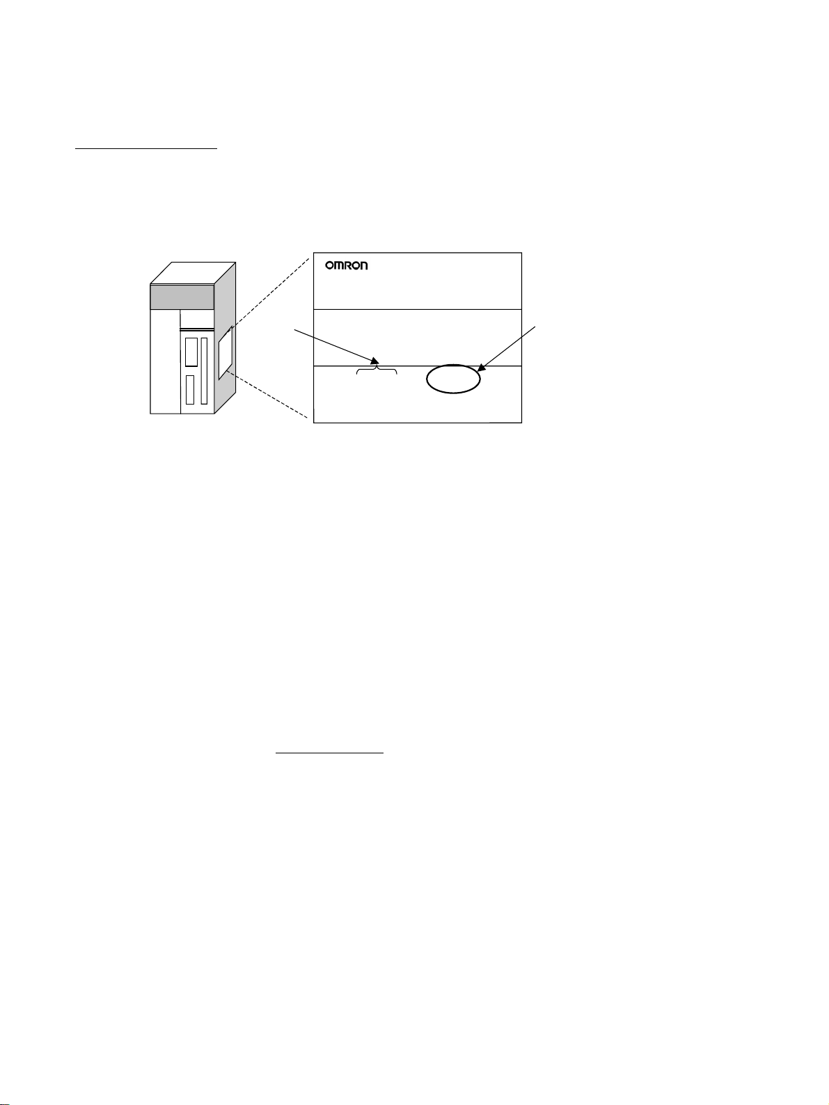
Notation of Unit Versions
on Products
CS/CJ-series CPU Unit
The unit version is given to the right of the lot number on the nameplate of the
products for which unit versions are being managed, as shown below.
Product nameplate
CS1H-CPU67H
CPU UNIT
Lot No.
Lot No. 031001 0000 Ver.2.0
OMRON Corporation MADE IN JAPAN
Unit version
Example for Unit version 2.0
• CS1-H, CJ1-H, and CJ1M CPU Units (except for low-end models) manufactured on or before November 4, 2003 do not have a unit version given
on the CPU Unit (i.e., the location for the unit version shown above is
blank).
• The unit version of the CS1-H, CJ1-H, and CJ1M CPU Units, as well as
the CS1D CPU Units for Single CPU Systems, begins at version 2.0.
• The unit version of the CS1D CPU Units for Duplex CPU Systems, begins
at version 1.1.
• CPU Units for which a unit version is not given are called Pre-Ver. @.@
CPU Units, such as Pre-Ver. 2.0 CPU Units and Pre-Ver. 1.1 CPU Units.
Confirming Unit Versions
with Support Software
CX-Programmer version 4.0 or later can be used to confirm the unit version
using one of the following two methods.
• Using the PLC Information
• Using the Unit Manufacturing Information (This method can be used for
Special I/O Units and CPU Bus Units as well.)
Note CX-Programmer version 3.3 or lower cannot be used to confirm unit versions.
PLC Information
• If you know the device type and CPU type, select them in the Change
PLC Dialog Box, go online, and select PLC - Edit - Information from the
menus.
• If you don’t know the device type and CPU type, but are connected
directly to the CPU Unit on a serial line, select PLC - Auto Online to go
online, and then select PLC - Edit - Information from the menus.
In either case, the following PLC Information Dialog Box will be displayed.
vi
Page 7
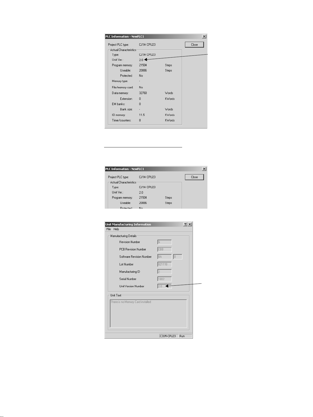
Unit version
Use the above display to confirm the unit version of the CPU Unit.
Unit Manufacturing Information
In the IO Table Window, right-click and select Unit Manufacturing informa-
tion - CPU Unit.
The following Unit Manufacturing information Dialog Box will be displayed.
Unit version
Use the above display to confirm the unit version of the CPU Unit connected
online.
vii
Page 8
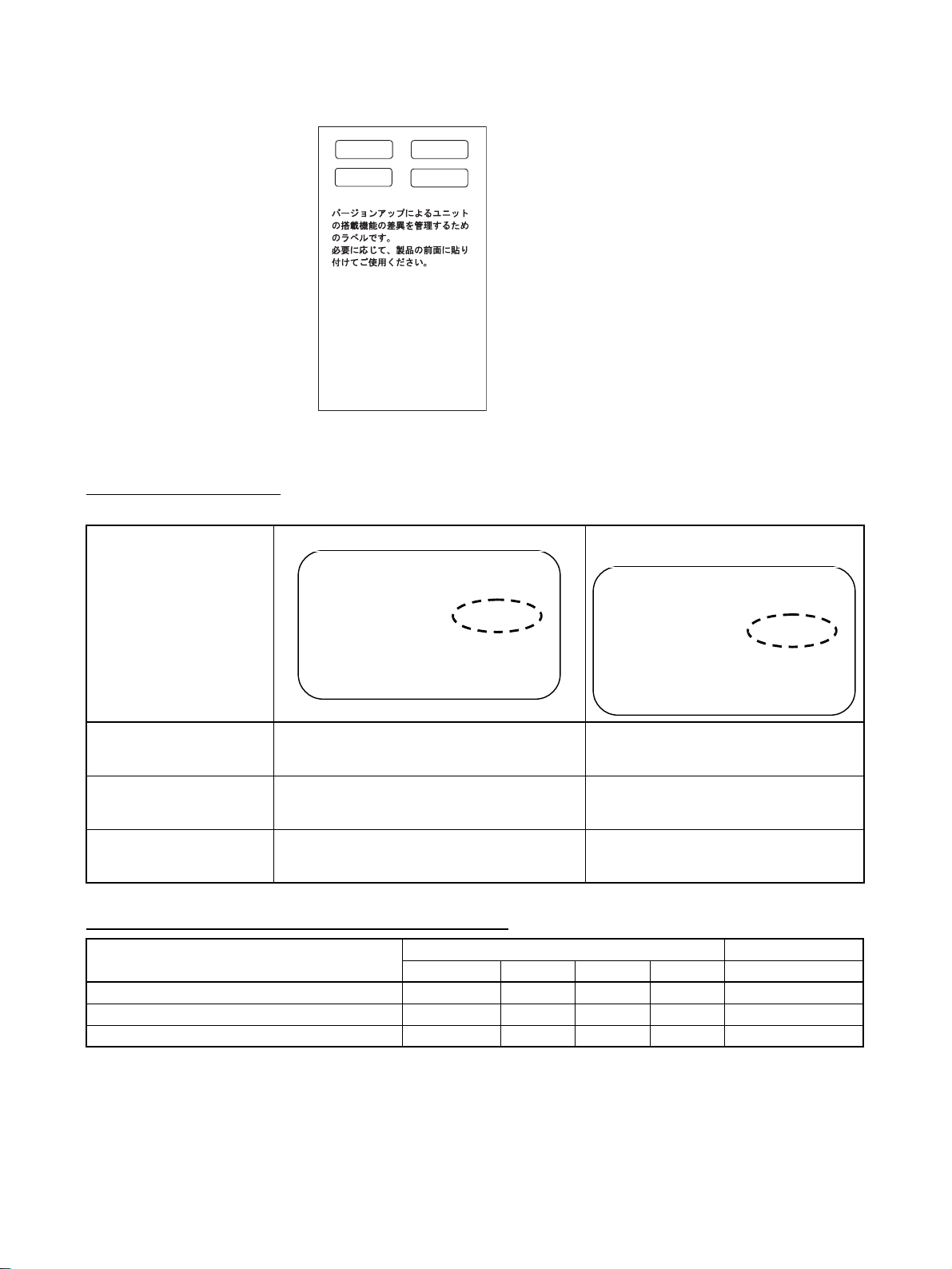
Using the Unit Version
Labels
The following unit version labels are provided with the CPU Unit.
Ver.
2.0
Ver.
2.0
These Labels can be
used to manage
differences in the
available functions
among the Units.
Place the appropriate
label on the front of
the Unit to show what
Unit version is
actually being used.
Ver.
Ver.
These labels can be attached to the front of previous CPU Units to differentiate between CPU Units of different unit versions.
Unit Version Notation In this manual, the unit version of a CPU Unit is given as shown in the follow-
ing table.
Product nameplate
CPU Units on which no unit version is given Units on which a version is given
(Ver. @.@)
Lot No. XXXXXX XXXX
OMRON Corporation MADE IN JAPAN
Lot No. XXXXXX XXXX
OMRON Corporation MADE IN JAPAN
Meaning
Designating individual CPU
Pre-Ver. 2.0 CS1-H CPU Units CS1H-CPU67H CPU Unit Ver. @.@
Units (e.g., the CS1HCPU67H)
Designating groups of CPU
Pre-Ver. 2.0 CS1-H CPU Units CS1-H CPU Units Ver. @.@
Units (e.g., the CS1-H CPU
Units)
Designating an entire series
Pre-Ver. 2.0 CS-series CPU Units CS-series CPU Units Ver. @.@
of CPU Units (e.g., the CSseries CPU Units)
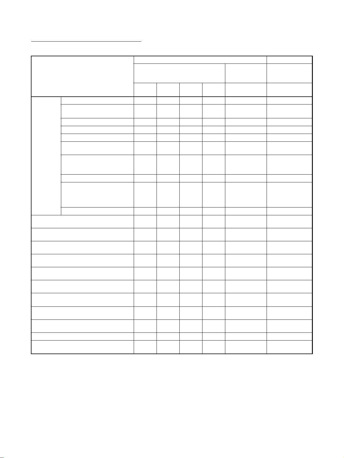
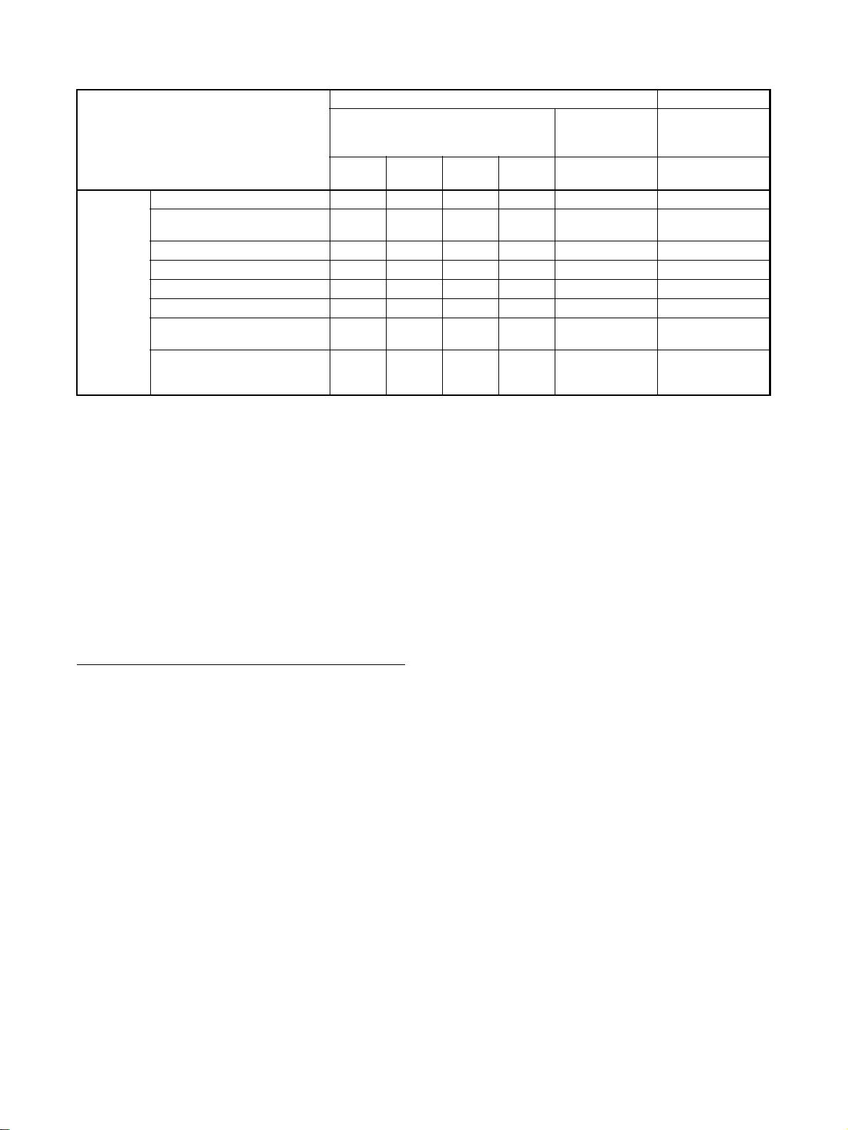
System Configuration Support by Unit Version
System configuration CS1D-CPU@@H/P CS1D-CPU@@S
Pre-Ver. 1.1 Ver. 1.1 Ver. 1.2 Ver. 1. 3 Ver. 2.0
Duplex CPU, Dual I/O Expansion System --- --- --- OK --Duplex CPU, Single I/O Expansion System OK OK OK OK --Single CPU System --- --- --- --- OK
Note 1. OK: Supported, ---: Not supported
Ver.
.
viii
2. Only CS1D-CPU@@H/P CPU Units with unit version 1.3 support the Du-
plex CPU, Dual I/O Expansion System. If a Dual I/O Expansion System is
connected to a CPU Unit with an earlier unit version, an I/O bus error will
occur and the PLC will not operate.
Page 9
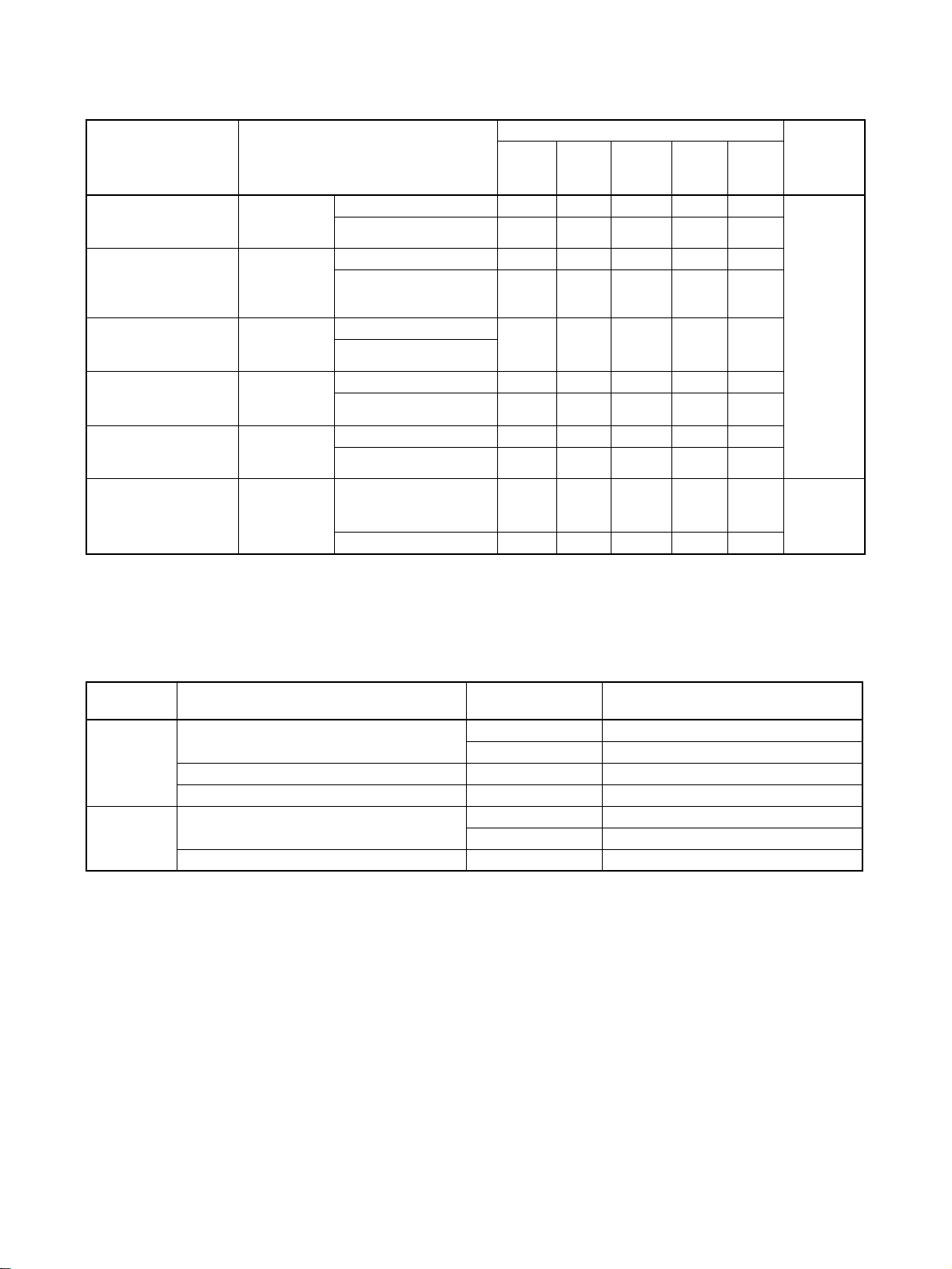
Function Support by Unit Version
CS1D CPU Units
Function CS1D-CPU@@H CS1D-CPU@@S
Duplex CPU, Single I/O Expansion
System
Pre-Ver.
1.1
Functions
unique to
CS1D CPU
Units
Downloading and Uploading Individual
Tasks
Improved Read Protection Using Passwords
Write Protection from FINS Commands
Sent to CPU Units via Networks
Online Network Connections without I/O
Ta bl e s
Communications through a Maximum of 8
Network Levels
Connecting Online to PLCs via NS-series
PTs
Setting First Slot Words --- --- --- --- --- OK for up to 64
Automatic Transfers at Power ON without a
Parameter File
Automatic Detection of I/O Allocation
Method for Automatic Transfer at Power ON
Operation Start/End Times --- OK OK OK OK OK
Automatic Allocation of Communications
Por ts
Duplex CPU Units OK OK OK OK OK --Online Unit Replacement
using a Programming Device
Duplex Power Supply Units OK OK OK OK OK OK
Duplex Controller Link Units OK OK OK OK OK OK
Duplex Ethernet Units --- OK OK OK OK OK
Unit Removal without a Pro-
gramming Device
Removal/Addition of Units
without a Programming
Device (See note 2.)
Duplex Connecting Cables --- --- --- --- OK --Online Addition of Units and
Backplanes
Online Addition of Duplex Unit --- --- --- --- OK OK
OK OK OK OK OK OK
--- --- OK OK OK ---
--- --- --- --- OK (See note 2.) ---
--- --- --- OK
--- --- --- --- --- OK
--- --- --- --- --- OK
--- --- --- --- --- OK
--- --- --- --- --- OK
--- --- --- --- --- OK
--- --- --- --- --- OK
--- --- --- --- --- OK
--- --- --- --- --- ---
--- --- --- OK OK OK
Ver. 1.1 Ver. 1. 2 Ver. 1. 3 Ver. 1.3 Ver. 2.0
(See
notes 3
and 4.)
Duplex CPU,
Dual I/O Expan-
sion System
OK (See note 3.) ---
groups
CS1D CPU Units
for Single CPU
Systems
ix
Page 10
New Application
Instructions
Function CS1D-CPU@@H CS1D-CPU@@S
Duplex CPU, Single I/O Expansion
Pre-Ver.
1.1
MILH, MILR, MILC --- --- --- --- --- OK
=DT, <>DT, <DT, <=DT, >DT,
>=DT
BCMP2 --- --- --- --- --- OK
GRY --- --- --- --- --- OK
TPO --- --- --- --- --- OK
DSW, TKY, HKY, MTR, 7SEG --- --- --- --- --- OK
EXPLT, EGATR, ESATR,
ECHRD, ECHWR
Reading/Writing CPU Bus
Units with IORD/IOWR
Instructions
--- --- --- --- --- OK
--- --- --- --- --- OK
--- --- --- --- --- OK
System
Ver. 1.1 Ver. 1.2 Ver. 1.3 Ver. 1.3 Ver. 2.0
Duplex CPU,
Dual I/O Expan-
sion System
CS1D CPU Units
for Single CPU
Systems
Note 1. OK: Supported, ---: Not supported
2. The Removal/Addition of Units without a Programming Device function is
supported only by CS1D CPU Units with unit version 1.3 or later and a Duplex CPU, Dual I/O Expansion System.
If the Removal/Addition of Units without a Programming Device function is
selected in a Duplex CPU, Single I/O Expansion System, the function will
operate as the earlier Unit Removal without a Programming Device func-
tion.
3. Basic I/O Units and Special I/O Units can be added for the Online Addition
of Units and Backplanes function. CPU Units cannot be added.
4. Expansion Backplanes cannot be added with a Duplex CPU, Single I/O Expansion System.
Unit Versions and Programming Devices
CX-Programmer version 7.0 or higher is required to use the functions added
to the CS1D-CPU@@H CPU Units in unit version 1.3 (Duplex CPU Systems).
CX-Programmer version 4.0 or higher is required to use the functions added
to the CS1D-CPU@@S CPU Units in unit version 2.0 (Single CPU Systems).
The following tables show the relationship between unit versions and CX-Programmer versions.
x
Page 11
Unit Versions and Programming Devices
CPU Unit Functions CX-Programmer Program-
CJ1M CPU Units,
low-end models, Unit
Ver. 2.0
CS1-H, CJ1-H, and
CJ1M CPU Units
except low-end
models, Unit Ver. 2.0
CS1D CPU Units for
Single CPU Systems,
Unit Ver. 2.0
CS1D CPU Units for
Duplex CPU
Systems, Unit Ver.1
CS1D Duplex CPU
Unit Ver. 1.2
CS1D Duplex CPU
Unit Ver. 1.3
Functions
added for unit
version 2.0
Functions
added for unit
version 2.0
Functions
added for unit
version 2.0
Functions
added for unit
version 1.1
Functions
upgraded in
Unit Ver. 1.2
Functions
upgraded in
Unit Ver. 1.3
Ver. 3.2
or
lower
Using new functions --- --- OK OK OK No
Not using new functions --- OK OK OK OK
Using new functions --- --- OK OK OK
Not using new functions OK OK OK OK OK
Using new functions --- --- OK OK OK
Not using new functions
Using new functions --- --- OK OK OK
Not using new functions OK OK OK OK OK
Using new functions --- --- --- OK OK
Not using new functions OK OK OK OK OK
Using new functions --- --- --- --- OK
Not using new functions OK OK OK OK OK
Ver.
3.3
Ver. 4. 0
to
Ver. 6.0
Ver.6.1 Ver.7.0
(See
note.)
ming
Console
restrictions
Online
addition of
Units is not
supported.
Note With CX-Programmer version 7.0, the auto update function can be used to
expand the Unit’s functions.
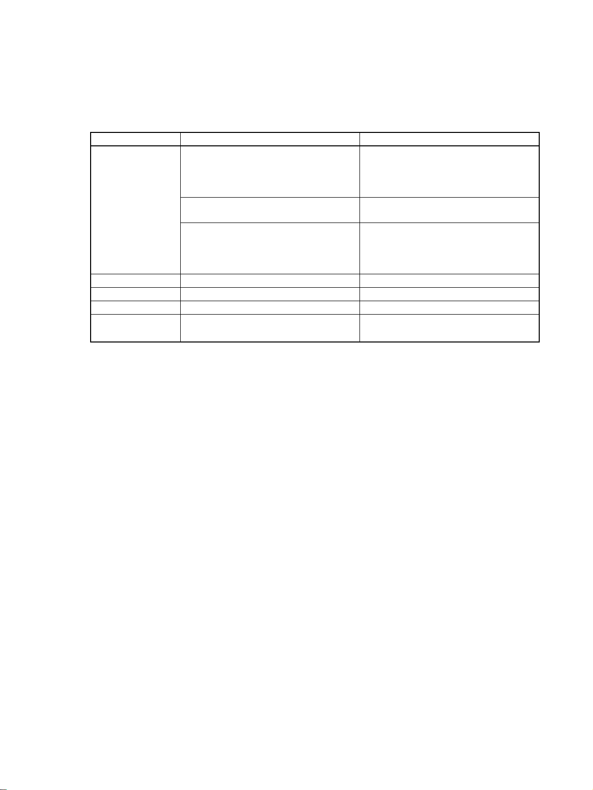
Device Type Setting The unit version does not affect the setting made for the device type on the
CX-Programmer. Select the device type as shown in the following table
regardless of the unit version of the CPU Unit.
Series CPU Unit group CPU Unit model Device type setting on
CX-Programmer Ver. 4.0 or higher
CS Series CS1-H CPU Units CS1G-CPU@@H CS1G-H
CS1H-CPU@@H CS1H-H
CS1D CPU Units for Duplex CPU Systems CS1D-CPU@@H CS1D-H (or CS1H-H)
CS1D CPU Units for Single CPU Systems CS1D-CPU@@S CS1D-S
CJ Series CJ1-H CPU Units CJ1G-CPU@@H CJ1G-H
CJ1H-CPU@@H CJ1H-H
CJ1M CPU Units CJ1M-CPU@@ CJ1M
xi
Page 12
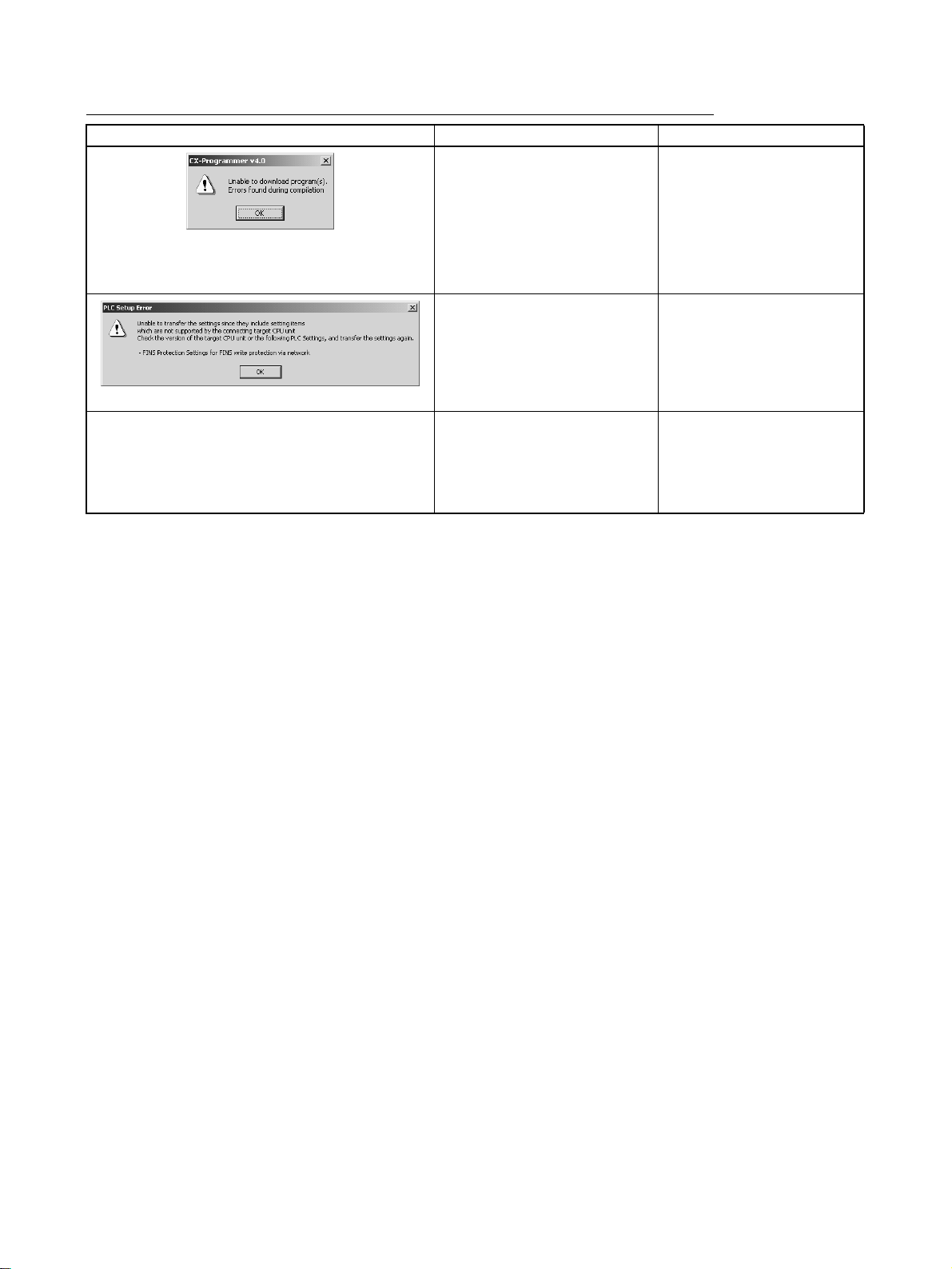
Troubleshooting Problems with Unit Versions on the CX-Programmer
Problem Cause Solution
After the above message is displayed, a compiling
error will be displayed on the Compile Tab Page in the
Output Window.
“????” is displayed in a program transferred from the
PLC to the CX-Programmer.
An attempt was made using CXProgrammer version 4.0 or higher
to download a program containing instructions supported only by
CPU Units Ver. 2.0 or later to a
Pre-Ver. 2.0 CPU Units.
An attempt was made using CXProgrammer version 4.0 or higher
to download a PLC Setup containing settings supported only by
CPU Units Ver. 2.0 or later (i.e.,
not set to their default values) to a
Pre-Ver. 2.0 CPU Units.
CX-Programmer version 3.3 or
lower was used to upload a program containing instructions supported only by CPU Units Ver. 2.0
or later from a CPU Unit Ver. 2.0
or later.
Check the program or change
the CPU Unit being downloaded to a CPU Unit Ver. 2.0
or later.
Check the settings in the PLC
Setup or change the CPU Unit
being downloaded to a CPU
Unit Ver. 2.0 or later.
The new instructions cannot
be uploaded using CX-Programmer version 3.3 or lower.
Use CX-Programmer version
4.0 or higher.
xii
Page 13

TABLE OF CONTENTS
PRECAUTIONS . . . . . . . . . . . . . . . . . . . . . . . . . . . . . . . . . . . xxiii
1 Intended Audience . . . . . . . . . . . . . . . . . . . . . . . . . . . . . . . . . . . . . . . . . . . . . . . . . . . . . . . . . xxiv
2 General Precautions . . . . . . . . . . . . . . . . . . . . . . . . . . . . . . . . . . . . . . . . . . . . . . . . . . . . . . . . xxiv
3 Safety Precautions . . . . . . . . . . . . . . . . . . . . . . . . . . . . . . . . . . . . . . . . . . . . . . . . . . . . . . . . . xxiv
4 Operating Environment Precautions . . . . . . . . . . . . . . . . . . . . . . . . . . . . . . . . . . . . . . . . . . . xxvi
5 Application Precautions. . . . . . . . . . . . . . . . . . . . . . . . . . . . . . . . . . . . . . . . . . . . . . . . . . . . . xxvii
6 Conformance to EC Directives . . . . . . . . . . . . . . . . . . . . . . . . . . . . . . . . . . . . . . . . . . . . . . . xxxiii
SECTION 1
Features and System Configuration . . . . . . . . . . . . . . . . . . . 1
1-1 CS1D Duplex System Overview and Features . . . . . . . . . . . . . . . . . . . . . . . . . . . . . . . . . . . 2
1-2 System Configuration . . . . . . . . . . . . . . . . . . . . . . . . . . . . . . . . . . . . . . . . . . . . . . . . . . . . . . 7
SECTION 2
Specifications, Nomenclature, and Functions . . . . . . . . . . . 15
2-1 Specifications. . . . . . . . . . . . . . . . . . . . . . . . . . . . . . . . . . . . . . . . . . . . . . . . . . . . . . . . . . . . . 17
2-2 Configuration Devices. . . . . . . . . . . . . . . . . . . . . . . . . . . . . . . . . . . . . . . . . . . . . . . . . . . . . . 30
2-3 Duplex Unit . . . . . . . . . . . . . . . . . . . . . . . . . . . . . . . . . . . . . . . . . . . . . . . . . . . . . . . . . . . . . . 45
2-4 CPU Units . . . . . . . . . . . . . . . . . . . . . . . . . . . . . . . . . . . . . . . . . . . . . . . . . . . . . . . . . . . . . . . 54
2-5 File Memory . . . . . . . . . . . . . . . . . . . . . . . . . . . . . . . . . . . . . . . . . . . . . . . . . . . . . . . . . . . . . 62
2-6 Programming Devices . . . . . . . . . . . . . . . . . . . . . . . . . . . . . . . . . . . . . . . . . . . . . . . . . . . . . .71
2-7 Power Supply Units . . . . . . . . . . . . . . . . . . . . . . . . . . . . . . . . . . . . . . . . . . . . . . . . . . . . . . . . 82
2-8 Backplanes. . . . . . . . . . . . . . . . . . . . . . . . . . . . . . . . . . . . . . . . . . . . . . . . . . . . . . . . . . . . . . . 85
2-9 Units for Duplex CPU, Dual I/O Expansion Systems . . . . . . . . . . . . . . . . . . . . . . . . . . . . . . 89
2-10 Units on CS1D Long-distance Expansion Racks . . . . . . . . . . . . . . . . . . . . . . . . . . . . . . . . . 94
2-11 Basic I/O Units . . . . . . . . . . . . . . . . . . . . . . . . . . . . . . . . . . . . . . . . . . . . . . . . . . . . . . . . . . . 98
2-12 Unit Current Consumption . . . . . . . . . . . . . . . . . . . . . . . . . . . . . . . . . . . . . . . . . . . . . . . . . .104
2-13 CPU Bus Unit Setting Area Capacity . . . . . . . . . . . . . . . . . . . . . . . . . . . . . . . . . . . . . . . . . . 108
2-14 I/O Table Settings . . . . . . . . . . . . . . . . . . . . . . . . . . . . . . . . . . . . . . . . . . . . . . . . . . . . . . . . . 109
SECTION 3
Duplex Functions . . . . . . . . . . . . . . . . . . . . . . . . . . . . . . . . . . 113
3-1 Duplex CPU Units . . . . . . . . . . . . . . . . . . . . . . . . . . . . . . . . . . . . . . . . . . . . . . . . . . . . . . . . . 114
3-2 Duplex Power Supply Units . . . . . . . . . . . . . . . . . . . . . . . . . . . . . . . . . . . . . . . . . . . . . . . . . 127
3-3 Duplex Communications Units . . . . . . . . . . . . . . . . . . . . . . . . . . . . . . . . . . . . . . . . . . . . . . . 127
3-4 Duplex Connecting Cables . . . . . . . . . . . . . . . . . . . . . . . . . . . . . . . . . . . . . . . . . . . . . . . . . . 130
SECTION 4
Operating Procedures. . . . . . . . . . . . . . . . . . . . . . . . . . . . . . . 133
4-1 Introduction . . . . . . . . . . . . . . . . . . . . . . . . . . . . . . . . . . . . . . . . . . . . . . . . . . . . . . . . . . . . . . 134
4-2 Basic Procedures . . . . . . . . . . . . . . . . . . . . . . . . . . . . . . . . . . . . . . . . . . . . . . . . . . . . . . . . . . 136
xiii
Page 14

TABLE OF CONTENTS
SECTION 5
Installation and Wiring . . . . . . . . . . . . . . . . . . . . . . . . . . . . . 149
5-1 Fail-safe Circuits . . . . . . . . . . . . . . . . . . . . . . . . . . . . . . . . . . . . . . . . . . . . . . . . . . . . . . . . . . 150
5-2 Installation . . . . . . . . . . . . . . . . . . . . . . . . . . . . . . . . . . . . . . . . . . . . . . . . . . . . . . . . . . . . . . . 151
5-3 Power Supply Wiring. . . . . . . . . . . . . . . . . . . . . . . . . . . . . . . . . . . . . . . . . . . . . . . . . . . . . . . 165
5-4 Wiring Methods. . . . . . . . . . . . . . . . . . . . . . . . . . . . . . . . . . . . . . . . . . . . . . . . . . . . . . . . . . . 167
SECTION 6
PLC Setup . . . . . . . . . . . . . . . . . . . . . . . . . . . . . . . . . . . . . . . . 187
6-1 Overview of PLC Setup. . . . . . . . . . . . . . . . . . . . . . . . . . . . . . . . . . . . . . . . . . . . . . . . . . . . .188
6-2 Specific PLC Setup Settings . . . . . . . . . . . . . . . . . . . . . . . . . . . . . . . . . . . . . . . . . . . . . . . . .191
SECTION 7
I/O Allocations. . . . . . . . . . . . . . . . . . . . . . . . . . . . . . . . . . . . . 221
7-1 I/O Allocations. . . . . . . . . . . . . . . . . . . . . . . . . . . . . . . . . . . . . . . . . . . . . . . . . . . . . . . . . . . . 222
7-2 I/O Allocation Methods . . . . . . . . . . . . . . . . . . . . . . . . . . . . . . . . . . . . . . . . . . . . . . . . . . . . . 228
7-3 Allocating First Words to Racks . . . . . . . . . . . . . . . . . . . . . . . . . . . . . . . . . . . . . . . . . . . . . . 234
7-4 Allocating First Words to Slots (Single CPU Systems Only) . . . . . . . . . . . . . . . . . . . . . . . . 237
7-5 Detailed Information on I/O Table Creation Errors. . . . . . . . . . . . . . . . . . . . . . . . . . . . . . . . 240
7-6 Data Exchange with CPU Bus Units . . . . . . . . . . . . . . . . . . . . . . . . . . . . . . . . . . . . . . . . . . . 241
7-7 Online Addition of Units and Backplanes. . . . . . . . . . . . . . . . . . . . . . . . . . . . . . . . . . . . . . . 245
SECTION 8
Memory Areas. . . . . . . . . . . . . . . . . . . . . . . . . . . . . . . . . . . . . 251
8-1 Introduction . . . . . . . . . . . . . . . . . . . . . . . . . . . . . . . . . . . . . . . . . . . . . . . . . . . . . . . . . . . . . . 252
8-2 I/O Memory Areas. . . . . . . . . . . . . . . . . . . . . . . . . . . . . . . . . . . . . . . . . . . . . . . . . . . . . . . . . 253
8-3 I/O Area . . . . . . . . . . . . . . . . . . . . . . . . . . . . . . . . . . . . . . . . . . . . . . . . . . . . . . . . . . . . . . . . . 260
8-4 CS-series DeviceNet Area . . . . . . . . . . . . . . . . . . . . . . . . . . . . . . . . . . . . . . . . . . . . . . . . . . .266
8-5 Data Link Area . . . . . . . . . . . . . . . . . . . . . . . . . . . . . . . . . . . . . . . . . . . . . . . . . . . . . . . . . . . 267
8-6 CPU Bus Unit Area . . . . . . . . . . . . . . . . . . . . . . . . . . . . . . . . . . . . . . . . . . . . . . . . . . . . . . . . 268
8-7 Inner Board Area . . . . . . . . . . . . . . . . . . . . . . . . . . . . . . . . . . . . . . . . . . . . . . . . . . . . . . . . . . 270
8-8 Special I/O Unit Area . . . . . . . . . . . . . . . . . . . . . . . . . . . . . . . . . . . . . . . . . . . . . . . . . . . . . . 271
8-9 Work Area . . . . . . . . . . . . . . . . . . . . . . . . . . . . . . . . . . . . . . . . . . . . . . . . . . . . . . . . . . . . . . . 272
8-10 Holding Area . . . . . . . . . . . . . . . . . . . . . . . . . . . . . . . . . . . . . . . . . . . . . . . . . . . . . . . . . . . . . 273
8-11 Auxiliary Area . . . . . . . . . . . . . . . . . . . . . . . . . . . . . . . . . . . . . . . . . . . . . . . . . . . . . . . . . . . . 274
8-12 TR (Temporary Relay) Area . . . . . . . . . . . . . . . . . . . . . . . . . . . . . . . . . . . . . . . . . . . . . . . . . 304
8-13 Timer Area. . . . . . . . . . . . . . . . . . . . . . . . . . . . . . . . . . . . . . . . . . . . . . . . . . . . . . . . . . . . . . . 305
8-14 Counter Area . . . . . . . . . . . . . . . . . . . . . . . . . . . . . . . . . . . . . . . . . . . . . . . . . . . . . . . . . . . . . 307
8-15 Data Memory (DM) Area . . . . . . . . . . . . . . . . . . . . . . . . . . . . . . . . . . . . . . . . . . . . . . . . . . . 307
8-16 Extended Data Memory (EM) Area . . . . . . . . . . . . . . . . . . . . . . . . . . . . . . . . . . . . . . . . . . . 310
8-17 Index Registers . . . . . . . . . . . . . . . . . . . . . . . . . . . . . . . . . . . . . . . . . . . . . . . . . . . . . . . . . . . 311
8-18 Data Registers . . . . . . . . . . . . . . . . . . . . . . . . . . . . . . . . . . . . . . . . . . . . . . . . . . . . . . . . . . . . 317
xiv
Page 15

TABLE OF CONTENTS
8-19 Task Flags . . . . . . . . . . . . . . . . . . . . . . . . . . . . . . . . . . . . . . . . . . . . . . . . . . . . . . . . . . . . . . . 318
8-20 Condition Flags . . . . . . . . . . . . . . . . . . . . . . . . . . . . . . . . . . . . . . . . . . . . . . . . . . . . . . . . . . . 319
8-21 Clock Pulses . . . . . . . . . . . . . . . . . . . . . . . . . . . . . . . . . . . . . . . . . . . . . . . . . . . . . . . . . . . . . 322
8-22 Parameter Areas. . . . . . . . . . . . . . . . . . . . . . . . . . . . . . . . . . . . . . . . . . . . . . . . . . . . . . . . . . . 323
SECTION 9
CPU Unit Operation and the Cycle Time. . . . . . . . . . . . . . . 327
9-1 CPU Unit Operation . . . . . . . . . . . . . . . . . . . . . . . . . . . . . . . . . . . . . . . . . . . . . . . . . . . . . . . 329
9-2 CPU Unit Operating Modes. . . . . . . . . . . . . . . . . . . . . . . . . . . . . . . . . . . . . . . . . . . . . . . . . . 336
9-3 Power OFF Operation . . . . . . . . . . . . . . . . . . . . . . . . . . . . . . . . . . . . . . . . . . . . . . . . . . . . . . 338
9-4 Computing the Cycle Time . . . . . . . . . . . . . . . . . . . . . . . . . . . . . . . . . . . . . . . . . . . . . . . . . . 342
9-5 Instruction Execution Times and Number of Steps . . . . . . . . . . . . . . . . . . . . . . . . . . . . . . . . 358
SECTION 10
Troubleshooting . . . . . . . . . . . . . . . . . . . . . . . . . . . . . . . . . . . 387
10-1 Error Log . . . . . . . . . . . . . . . . . . . . . . . . . . . . . . . . . . . . . . . . . . . . . . . . . . . . . . . . . . . . . . . . 388
10-2 Error Processing. . . . . . . . . . . . . . . . . . . . . . . . . . . . . . . . . . . . . . . . . . . . . . . . . . . . . . . . . . . 389
10-3 Troubleshooting Racks and Units . . . . . . . . . . . . . . . . . . . . . . . . . . . . . . . . . . . . . . . . . . . . . 416
10-4 Troubleshooting Errors in Duplex Connecting Cables . . . . . . . . . . . . . . . . . . . . . . . . . . . . . 419
SECTION 11
Inspection and Maintenance . . . . . . . . . . . . . . . . . . . . . . . . . 423
11-1 Inspections . . . . . . . . . . . . . . . . . . . . . . . . . . . . . . . . . . . . . . . . . . . . . . . . . . . . . . . . . . . . . . . 424
11-2 Replacing User-serviceable Parts . . . . . . . . . . . . . . . . . . . . . . . . . . . . . . . . . . . . . . . . . . . . . 426
11-3 Replacing a CPU Unit . . . . . . . . . . . . . . . . . . . . . . . . . . . . . . . . . . . . . . . . . . . . . . . . . . . . . . 432
11-4 Online Replacement of I/O Units, Special I/O Units, and CPU Bus Units . . . . . . . . . . . . . . 435
11-5 Replacing Power Supply Unit . . . . . . . . . . . . . . . . . . . . . . . . . . . . . . . . . . . . . . . . . . . . . . . . 455
11-6 Replacement of Expansion Units. . . . . . . . . . . . . . . . . . . . . . . . . . . . . . . . . . . . . . . . . . . . . . 455
11-7 Replacing the Duplex Unit . . . . . . . . . . . . . . . . . . . . . . . . . . . . . . . . . . . . . . . . . . . . . . . . . .457
Appendices
A Specifications of Basic I/O Units and High-density I/O Units . . . . . . . . . . . . . . . . . . . . . . . 461
B Auxiliary Area Allocations . . . . . . . . . . . . . . . . . . . . . . . . . . . . . . . . . . . . . . . . . . . . . . . . . . 501
C Memory Map of PLC Memory Addresses . . . . . . . . . . . . . . . . . . . . . . . . . . . . . . . . . . . . . . 549
D PLC Setup Coding Sheets for Programming Console . . . . . . . . . . . . . . . . . . . . . . . . . . . . . 551
E Precautions in Replacing CS1-H PLCs with CS1D PLCs . . . . . . . . . . . . . . . . . . . . . . . . . . 565
F Connecting to the RS-232C Port on the CPU Unit . . . . . . . . . . . . . . . . . . . . . . . . . . . . . . . 573
G CJ1W-CIF11 RS-422A Converter . . . . . . . . . . . . . . . . . . . . . . . . . . . . . . . . . . . . . . . . . . . . 583
Index. . . . . . . . . . . . . . . . . . . . . . . . . . . . . . . . . . . . . . . . . . . . . 589
Revision History . . . . . . . . . . . . . . . . . . . . . . . . . . . . . . . . . . . 597
xv
Page 16

TABLE OF CONTENTS
xvi
Page 17
About this Manual:
This manual describes the installation and operation of the CS1D Duplex Programmable Controllers
(PLCs) and includes the sections described below. The CS Series and CJ Series are subdivided as
shown in the following table.
Unit CS Series CJ Series
CPU Units CS1-H CPU Units: CS1H-CPU@@H
CS1 CPU Units: CS1H-CPU@@-EV1
CS1D CPU Units: CS1D-CPU@@H
CS1D Process-control CPU Units:
Basic I/O Units CS-series Basic I/O Units CJ-series Basic I/O Units
Special I/O Units CS-series Special I/O Units CJ-series Special I/O Units
CPU Bus Units CS-series CPU Bus Units CJ-series CPU Bus Units
Power Supply Units CS-series Power Supply Units
CS1D Power Supply Units
Please read this manual and all related manuals listed in the table on the next page and be sure you
understand information provided before attempting to install or use CS1D-CPU@@H/S CPU Units in a
PLC System.
Process-control CPU Units refer to CPU Units with the models CS1D-CPU@@P. Each Process-control
CPU Unit consists of a CS1D-CPU@@H CS1D CPU Unit and a CS1D-LCB05D Loop Control Board as
a set.
Precautions provides general precautions for using the CS1D Programmable Controllers (PLCs) and
related devices, including the CS1D-CPU@@H CPU Units for Duplex CPU Systems, CS1D-CPU@@S
CPU Units for Single CPU Systems, CS1D-DPL01 Duplex Unit, and CS1D-PA/PD@@@ Power Supply
Unit.
Section 1 introduces the special features and functions of the CS1D Duplex PLCs and describes the
differences between these PLCs and other PLCs.
Section 2 provides the specifications, defines the nomenclature, and describes the functions of CS1D
PLCs.
Section 3 describes the basic operation of a Duplex System.
Section 4 outlines the steps required to assemble and operate a CS1D Duplex PLC system.
Section 5 describes how to install a PLC System, including mounting the various Units and wiring the
System. Be sure to follow the instructions carefully. Improper installation can cause the PLC to malfunction, resulting in very dangerous situations.
Section 6 describes the settings in the PLC Setup and how they are used to control CPU Unit operation.
Section 7 describes I/O allocations to Basic I/O Units, Special I/O Units, and CPU Bus Units, and data
exchange with Units.
Section 8 describes the structure and functions of the I/O Memory Areas and Parameter Areas.
Section 9 describes the internal operation of the CPU Unit and the cycle used to perform internal pro-
cessing.
Section 10 provides information on hardware and software errors that occur during PLC operation.
Section 11 provides inspection and maintenance information.
The Appendices provide Unit specifications, Auxiliary Area words and bits, a memory map of internal
addresses, and PLC Setup coding sheets, RS-232C port connection information, and precautions
when upgrading a system to duplex operation with CS1D PLCs
CS1G-CPU@@H
CS1G-CPU@@-EV1
CS1D-CPU@@S
CS1D-CPU@@P
CJ1-H CPU Units: CJ1H-CPU@@H
CJ1G-CPU@@H
CJ1-H Loop-control CPU Units:
CJ1G-CPU@@H
CJ1 CPU Units: CJ1G-CPU@@-EV1
CJ1M CPU Units: CJ1M-CPU@@
CJ-series Power Supply Units
xvii
Page 18

About this Manual, Continued
Name Cat. No. Contents
SYSMAC CS Series
CS1D-CPU@@H CPU Units
CS1D-CPU@@S CPU Units
CS1D-DPL01/02D Duplex Unit
CS1D-PA/PD@@@ Power Supply Unit
Duplex System Operation Manual
SYSMAC CS/CJ/NSJ Series
CS1G/H-CPU@@-EV1, CS1G/H-CPU@@H,
CS1D-CPU@@H, CS1D-CPU@@S, CJ1G-CPU@@,
CJ1M-CPU@@, CJ1G-CPU@@P, CJ1G/H-CPU@@H,
NSJ@-@@@@(B)-G5D, NSJ@-@@@@(B)-M3D
Programmable Controllers Programming Manual
SYSMAC CS/CJ/NSJ Series
CS1G/H-CPU@@-EV1, CS1G/H-CPU@@H,
CS1D-CPU@@H, CS1D-CPU@@S, CJ1G-CPU@@,
CJ1M-CPU@@, CJ1G-CPU@@P, CJ1G/H-CPU@@H,
NSJ@-@@@@(B)-G5D, NSJ@-@@@@(B)-M3D
Programmable Controllers Instructions Reference Manual
SYSMAC CS/CJ Series
CQM1H-PRO01-E, C200H-PRO27-E, CQM1-PRO01-E
Programming Consoles Operation Manual
SYSMAC CS/CJ/CP/NSJ Series
CS1G/H-CPU@@-EV1, CS1G/H-CPU@@H, CS1D-CPU@@H,
CS1D-CPU@@S, CJ1G-CPU@@, CJ1M-CPU@@, CJ1GCPU@@P, C J1 G/ H- CP U@@H, CS1W-SCU@@-V1, CS1WSCB@@-V1, CJ1W-SCU@@-V1, CP1H-X@@@@-@, CP1HXA@@@@-@, CP1H-Y@@@@-@,
NSJ@-@@@@(B)-G5D, NSJ@-@@@@(B)-M3D
Communications Commands Reference Manual
SYSMAC
WS02-CXPC1-E-V70
CX-Programmer Ver. 7.0 Operation Manual
SYSMAC CX-Programmer Ver. 7.0
WS02-CXPC1-E-V7, CS1-H, CJ1-H, CJ1M, CP1H CPU Units,
NSJ, FQM1
Operation Manual: Function Blocks
SYSMAC WS02-PSTC1-E
CX-Protocol Operation Manual
SYSMAC CS/CJ Series Loop Control Boards/Process-control
CPU Units/Loop-control CPU Units
CS1W-LCB01/LCB05, CS1D-CPU@@P, CJ1G-CPU42P,
CJ1G-CPU43P/44P/45P
Operation Manual
CS1D-ETN21D
Ethernet Unit Operation Manual
W405 Provides an outline of and describes the design,
installation, maintenance, and other basic operations
for a Duplex System based on CS1D CPU Units.
(This manual)
W394 This manual describes programming and other meth-
ods to use the functions of the CS/CJ-series PLCs
and NSJ Controllers.
W340 Describes the ladder diagram programming instruc-
tions supported by CS/CJ-series PLCs and NSJ Controllers.
W341 Provides information on how to program and operate
CS/CJ-series PLCs using a Programming Console.
W342 Describes the communications commands used with
CS-series, CJ-series, and CP-series PLCs and NSJ
Controllers.
W446 Describes operating procedures for the CX-Program-
mer Support Software running on a Windows computer.
W447 Describes specifications and procedures required to
use function blocks.
W344 Describes the use of the CX-Protocol to create proto-
col macros as communications sequences to communicate with external devices.
W406 Provides information on how to operate CS1 Loop
Control Boards, including descriptions of the installation, maintenance, and other basic operations.
W430 Provides information on how to operateCS1D Ether-
net Units, including descriptions of the installation,
maintenance, and other basic operations.
!WARNING Failure to read and understand the information provided in this manual may result in per-
sonal injury or death, damage to the product, or product failure. Please read each section
in its entirety and be sure you understand the information provided in the section and
related sections before attempting any of the procedures or operations given.
xviii
Page 19

Read and Understand this Manual
Please read and understand this manual before using the product. Please consult your OMRON
representative if you have any questions or comments.
Warranty and Limitations of Liability
WARRANTY
OMRON's exclusive warranty is that the products are free from defects in materials and workmanship for a
period of one year (or other period if specified) from date of sale by OMRON.
OMRON MAKES NO WARRANTY OR REPRESENTATION, EXPRESS OR IMPLIED, REGARDING NONINFRINGEMENT, MERCHANTABILITY, OR FITNESS FOR PARTICULAR PURPOSE OF THE
PRODUCTS. ANY BUYER OR USER ACKNOWLEDGES THAT THE BUYER OR USER ALONE HAS
DETERMINED THAT THE PRODUCTS WILL SUITABLY MEET THE REQUIREMENTS OF THEIR
INTENDED USE. OMRON DISCLAIMS ALL OTHER WARRANTIES, EXPRESS OR IMPLIED.
LIMITATIONS OF LIABILITY
OMRON SHALL NOT BE RESPONSIBLE FOR SPECIAL, INDIRECT, OR CONSEQUENTIAL DAMAGES,
LOSS OF PROFITS OR COMMERCIAL LOSS IN ANY WAY CONNECTED WITH THE PRODUCTS,
WHETHER SUCH CLAIM IS BASED ON CONTRACT, WARRANTY, NEGLIGENCE, OR STRICT
LIABILITY.
In no event shall the responsibility of OMRON for any act exceed the individual price of the product on which
liability is asserted.
IN NO EVENT SHALL OMRON BE RESPONSIBLE FOR WARRANTY, REPAIR, OR OTHER CLAIMS
REGARDING THE PRODUCTS UNLESS OMRON'S ANALYSIS CONFIRMS THAT THE PRODUCTS
WERE PROPERLY HANDLED, STORED, INSTALLED, AND MAINTAINED AND NOT SUBJECT TO
CONTAMINATION, ABUSE, MISUSE, OR INAPPROPRIATE MODIFICATION OR REPAIR.
xix
Page 20

Application Considerations
SUITABILITY FOR USE
OMRON shall not be responsible for conformity with any standards, codes, or regulations that apply to the
combination of products in the customer's application or use of the products.
At the customer's request, OMRON will provide applicable third party certification documents identifying
ratings and limitations of use that apply to the products. This information by itself is not sufficient for a
complete determination of the suitability of the products in combination with the end product, machine,
system, or other application or use.
The following are some examples of applications for which particular attention must be given. This is not
intended to be an exhaustive list of all possible uses of the products, nor is it intended to imply that the uses
listed may be suitable for the products:
• Outdoor use, uses involving potential chemical contamination or electrical interference, or conditions or
uses not described in this manual.
• Nuclear energy control systems, combustion systems, railroad systems, aviation systems, medical
equipment, amusement machines, vehicles, safety equipment, and installations subject to separate
industry or government regulations.
• Systems, machines, and equipment that could present a risk to life or property.
Please know and observe all prohibitions of use applicable to the products.
NEVER USE THE PRODUCTS FOR AN APPLICATION INVOLVING SERIOUS RISK TO LIFE OR
PROPERTY WITHOUT ENSURING THAT THE SYSTEM AS A WHOLE HAS BEEN DESIGNED TO
ADDRESS THE RISKS, AND THAT THE OMRON PRODUCTS ARE PROPERLY RATED AND INSTALLED
FOR THE INTENDED USE WITHIN THE OVERALL EQUIPMENT OR SYSTEM.
PROGRAMMABLE PRODUCTS
OMRON shall not be responsible for the user's programming of a programmable product, or any
consequence thereof.
xx
Page 21

Disclaimers
CHANGE IN SPECIFICATIONS
Product specifications and accessories may be changed at any time based on improvements and other
reasons.
It is our practice to change model numbers when published ratings or features are changed, or when
significant construction changes are made. However, some specifications of the products may be changed
without any notice. When in doubt, special model numbers may be assigned to fix or establish key
specifications for your application on your request. Please consult with your OMRON representative at any
time to confirm actual specifications of purchased products.
DIMENSIONS AND WEIGHTS
Dimensions and weights are nominal and are not to be used for manufacturing purposes, even when
tolerances are shown.
PERFORMANCE DATA
Performance data given in this manual is provided as a guide for the user in determining suitability and does
not constitute a warranty. It may represent the result of OMRON's test conditions, and the users must
correlate it to actual application requirements. Actual performance is subject to the OMRON Warranty and
Limitations of Liability.
ERRORS AND OMISSIONS
The information in this manual has been carefully checked and is believed to be accurate; however, no
responsibility is assumed for clerical, typographical, or proofreading errors, or omissions.
xxi
Page 22

xxii
Page 23

PRECAUTIONS
This section provides general precautions for using the CS1D Programmable Controllers (PLCs) and related devices,
including the CS1D-CPU@@H CPU Units for Duplex CPU Systems, CS1D-CPU@@S CPU Units for Single CPU
Systems, CS1D-DPL01 Duplex Unit, and CS1D-PA/PD@@@ Power Supply Unit.
The information contained in this section is important for the safe and reliable application of Programmable
Controllers. You must read this section and understand the information contained before attempting to set up or
operate a PLC system.
1 Intended Audience . . . . . . . . . . . . . . . . . . . . . . . . . . . . . . . . . . . . . . . . . . . . . xxiv
2 General Precautions . . . . . . . . . . . . . . . . . . . . . . . . . . . . . . . . . . . . . . . . . . . . xxiv
3 Safety Precautions . . . . . . . . . . . . . . . . . . . . . . . . . . . . . . . . . . . . . . . . . . . . . . xxiv
4 Operating Environment Precautions . . . . . . . . . . . . . . . . . . . . . . . . . . . . . . . . xxvi
5 Application Precautions . . . . . . . . . . . . . . . . . . . . . . . . . . . . . . . . . . . . . . . . . xxvii
6 Conformance to EC Directives . . . . . . . . . . . . . . . . . . . . . . . . . . . . . . . . . . . . xxxiii
6-1 Applicable Directives . . . . . . . . . . . . . . . . . . . . . . . . . . . . . . . . . . . . xxxiii
6-2 Concepts . . . . . . . . . . . . . . . . . . . . . . . . . . . . . . . . . . . . . . . . . . . . . . xxxiii
6-3 Conformance to EC Directives. . . . . . . . . . . . . . . . . . . . . . . . . . . . . xxxiii
6-4 Relay Output Noise Reduction Methods . . . . . . . . . . . . . . . . . . . . . xxxiv
xxiii
Page 24

Intended Audience 1
1 Intended Audience
This manual is intended for the following personnel, who must also have
knowledge of electrical systems (an electrical engineer or the equivalent).
• Personnel in charge of installing FA systems.
• Personnel in charge of designing FA systems.
• Personnel in charge of managing FA systems and facilities.
2 General Precautions
The user must operate the product according to the performance specifications described in the operation manuals.
Before using the product under conditions which are not described in the
manual or applying the product to nuclear control systems, railroad systems,
aviation systems, vehicles, combustion systems, medical equipment, amusement machines, safety equipment, and other systems, machines, and equipment that may have a serious influence on lives and property if used
improperly, consult your OMRON representative.
Make sure that the ratings and performance characteristics of the product are
sufficient for the systems, machines, and equipment, and be sure to provide
the systems, machines, and equipment with double safety mechanisms.
This manual provides information for programming and operating the Unit. Be
sure to read this manual before attempting to use the Unit and keep this manual close at hand for reference during operation.
!WARNING It is extremely important that a PLC and all PLC Units be used for the speci-
fied purpose and under the specified conditions, especially in applications that
can directly or indirectly affect human life. You must consult with your OMRON
representative before applying a PLC System to the above-mentioned applications.
3 Safety Precautions
!WARNING The CPU Unit refreshes I/O even when the program is stopped (i.e., even in
PROGRAM mode). Confirm safety thoroughly in advance before changing the
status of any part of memory allocated to I/O Units, Special I/O Units, or CPU
Bus Units. Any changes to the data allocated to any Unit may result in unexpected operation of the loads connected to the Unit. Any of the following operation may result in changes to memory status.
• Transferring I/O memory data to the CPU Unit from a Programming
Device.
• Changing present values in memory from a Programming Device.
• Force-setting/-resetting bits from a Programming Device.
• Transferring I/O memory files from a Memory Card or EM file memory to
the CPU Unit.
• Transferring I/O memory from a host computer or from another PLC on a
network.
xxiv
!WARNING Do not attempt to take any Unit apart while the power is being supplied. Doing
so may result in electric shock.
Page 25

Safety Precautions 3
!WARNING Do not touch any of the terminals or terminal blocks while the power is being
supplied. Doing so may result in electric shock.
!WARNING Do not attempt to disassemble, repair, or modify any Units. Any attempt to do
so may result in malfunction, fire, or electric shock.
!WARNING Do not touch the Power Supply Unit while power is being supplied or immedi-
ately after power has been turned OFF. Doing so may result in electric shock.
!WARNING Provide safety measures in external circuits (i.e., not in the Programmable
Controller), including the following items, to ensure safety in the system if an
abnormality occurs due to malfunction of the PLC or another external factor
affecting the PLC operation. Not doing so may result in serious accidents.
With a CS1D System operating in Duplex Mode, operation will be stopped
and all outputs will be turned OFF in the following circumstances.
• When self-diagnosis simultaneously detects an error in both the active
and standby CPU Units.
• When a severe failure alarm (FALS) instruction is simultaneously executed in both the active and standby CPU Units.
• When self-diagnosis detects an error in Simplex Mode or when it detects
an error during duplex initialization for Duplex Mode.
• When a severe failure alarm (FALS) instruction is executed in Simplex
Mode or during duplex initialization for Duplex Mode.
Unexpected operation, however, may still occur for errors in the I/O control
section, errors in I/O memory, and other errors that cannot be detected by the
self-diagnosis function. As a countermeasure for all such errors, external
safety measures must be provided to ensure safety in the system.
!WARNING The PLC outputs may remain ON or OFF due to deposition or burning of the
output relays or destruction of the output transistors. As a countermeasure for
such problems, external safety measures must be provided to ensure safety in
the system.
!WARNING When the 24-V DC output (service power supply to the PLC) is overloaded or
short-circuited, the voltage may drop and result in the outputs being turned
OFF. As a countermeasure for such problems, external safety measures must
be provided to ensure safety in the system.
!Caution Confirm safety before transferring data files stored in the file memory (Mem-
ory Card or EM file memory) to the I/O area (CIO) of the CPU Unit using a
peripheral tool. Otherwise, the devices connected to the output unit may malfunction regardless of the operation mode of the CPU Unit.
!Caution Fail-safe measures must be taken by the customer to ensure safety in the
event of incorrect, missing, or abnormal signals caused by broken signal lines,
momentary power interruptions, or other causes. Serious accidents may
result from abnormal operation if proper measures are not provided.
xxv
Page 26

Operating Environment Precautions 4
!Caution Execute online edit only after confirming that no adverse effects will be
caused by extending the cycle time. Otherwise, the input signals may not be
readable.
!Caution The CS1D CPU Units automatically back up the user program and parameter
data to flash memory when these are written to the CPU Unit. I/O memory
(including the DM, EM, and HR Areas), however, is not written to flash memory. The DM, EM, and HR Areas can be held during power interruptions with a
battery. If there is a battery error, the contents of these areas may not be
accurate after a power interruption. If the contents of the DM, EM, and HR
Areas are used to control external outputs, prevent inappropriate outputs from
being made whenever the Battery Error Flag (A40204) is ON.
!Caution Confirm safety at the destination node before transferring a program to
another node or changing contents of the I/O memory area. Doing either of
these without confirming safety may result in injury.
!Caution Tighten the screws on the terminal block of the AC Power Supply Unit to the
torque specified in the operation manual. The loose screws may result in
burning or malfunction.
!Caution Caution is required when connecting peripheral devices, such as a personal
computer, to the PLC when Units with non-isolated power supplies, such as
the CS1W-CLK12/CLK52(-V1), that are connected to an external power supply are mounted to the PLC. If the 24-V side is grounded on the external
power supply, a short will be created if the 0-V side of the peripheral device is
grounded. When connecting peripheral devices, either ground the 0-V side of
the external power supply or do not ground the external power supply at all.
4 Operating Environment Precautions
!Caution Do not operate the control system in the following locations:
• Locations subject to direct sunlight.
• Locations subject to temperatures or humidity outside the range specified
in the specifications.
• Locations subject to condensation as the result of severe changes in temperature.
• Locations subject to corrosive or flammable gases.
• Locations subject to dust (especially iron dust) or salts.
• Locations subject to exposure to water, oil, or chemicals.
• Locations subject to shock or vibration.
xxvi
!Caution Take appropriate and sufficient countermeasures when installing systems in
the following locations:
• Locations subject to static electricity or other forms of noise.
• Locations subject to strong electromagnetic fields.
• Locations subject to possible exposure to radioactivity.
• Locations close to power supplies.
Page 27

Application Precautions 5
!Caution The operating environment of the PLC System can have a large effect on the
longevity and reliability of the system. Improper operating environments can
lead to malfunction, failure, and other unforeseeable problems with the PLC
System. Be sure that the operating environment is within the specified conditions at installation and remains within the specified conditions during the life
of the system.
5 Application Precautions
Observe the following precautions when using the PLC System.
• Do not use the C200H/CS-series Power Supply Units (C200H-P@@@@)
in a CS1D PLC. System operation will not be dependable and may stop.
• Do not use a CS1D Power Supply Unit (CS1D-PA/PD@@@) for any PLC
other than a CS1D PLC. Operational errors and burning will result.
• If duplex Power Supply Units are to be used, calculate the current consumption so that the system will be able to operate with a single Power
Supply Unit in case an error occurs in the other Power Supply Unit. If two
different kinds of Power Supply Units are to be used, calculate the current
consumption using the output of the smaller-capacity Power Supply Unit.
• In a CS1D Duplex CPU System, always mount the CS1D-CPU@@H/P
CPU Units for Duplex CPU Systems to the CS1D-BC052/BC042D CPU
Backplane. Faulty operation will occur if any other CPU Unit is mounted.
• In a CS1D Single CPU System, always mount a CS1D-CPU@@S CPU
Unit for Single CPU Systems to the CS1D-BC82S CPU Backplane. Faulty
operation will occur if any other CPU Unit is mounted.
• Do not mount a CS1D-CPU@@H/P/S CPU Unit to a CS1W-BC@@ (nonCS1D) CPU Backplane. Otherwise, faulty operation will occur.
• The cycle time will be increased over the normal cycle time whenever
duplex operation is initialized, including when power is turned ON, when
the initialization button is pressed, when operation is started, and when
data is transferred. The increase will be a maximum of 190 ms for the
CS1D-CPU65H and 520 ms for the CS1D-CPU67H. Set the monitoring
time (10 to 40,000 ms, default: 1 s) for the cycle time high enough to allow
for this increase. Also, confirm that the system will operate correctly and
safely even for the maximum cycle time, including the increase for duplex
initialization.
• If operation switches from Duplex Mode to Simplex Mode, processing to
synchronize the active and standby CPU Units will no longer be performed, resulting in a shorter cycle time. The more instructions requiring
synchronization (such as IORF, DLNK, IORD, IOWR, PID, RXD, FREAD,
and FWRIT) are used, the greater the difference between Duplex Mode
and Simplex Mode operation will be (with Duplex Mode having the longer
cycle time). Confirm that the system will operate correctly and safely even
for the cycle time in both Simplex and Duplex Modes.
• If the active CPU Unit is switched when PTs or host computers are connected to the RS-232C port on both the active and standby CPU Units,
communications may be interrupted momentarily. Always enable retry
process in communications programs at the PTs or host computers.
• Before replacing a Unit online, always disable the operation of all connected external devices before starting the replacement procedure. Unexpected outputs from the Unit being replaced may result in unexpected
operation of controlled devices or systems.
xxvii
Page 28

Application Precautions 5
• Always following the procedures provided in the operation manual when
performing online replacement.
• When replacing a Unit online, always replace it with a Unit that has the
same specifications.
• When replacing a Duplex Unit online in a Duplex CPU, Dual I/O Expansion System, always follow the procedure provided in this operation manual.
• When replacing a Connecting Cable or Expansion Unit online in a Duplex
CPU, Dual I/O Expansion System, always follow the procedure provided
in this operation manual.
• When using duplex Connecting Cables in a Duplex CPU, Dual I/O Expansion System, always use cables that are the same length.
• In a Duplex CPU, Dual I/O Expansion System, do not connect two Connecting Cables to Expansion Backplanes that are in different operating
levels. Doing so may cause improper operation.
• Before removing a Unit during operation without a PLC Programming
Device (CX-Programmer or a Programming Console), always confirm that
the Removal of a Unit without a Programming Device or Removal/Addition
of Units without a Programming Device function is enabled in the PLC
Setup. If a Unit is removed while the PLC Setup is not set to enable Unit
removal without a Programming Device, an I/O bus error will occur and
the PLC (CPU Unit) will stop operating.
• When a Unit has been removed during operation without a PLC Programming Device (CX-Programmer or a Programming Console), data transferred from the removed Unit to the CPU Unit may be invalid. If an invalid
data transfer will adversely affect the system, use a Programming Device
to replace the Unit online.
• When the Removal of a Unit without a Programming Device or Removal/
Addition of Units without a Programming Device function is enabled in the
PLC Setup and a Special I/O Unit has been removed, the Special I/O Unit
Area words allocated to that Unit for data transfer (to and from the CPU
Unit) will be cleared. If the loss of the Special I/O Unit Area data will
adversely affect the system, disable these functions in the PLC Setup and
use a Programming Device to replace the Unit online. (When a Programming Device is used to replace the Unit online, the data in the Special I/O
Unit Area is retained while the Unit is removed.)
• An I/O bus error, which can be caused by a Unit malfunction, is normally a
fatal error that stops operation. When he Removal of a Unit without a Programming Device or Removal/Addition of Units without a Programming
Device function is enabled in the PLC Setup, the I/O bus error will be
treated as a non-fatal error and PLC (CPU Unit) will not stop operating. If
there are any Units that will adversely affect the system if an I/O bus error
occurs, do not enable these functions in the PLC Setup.
• Do not turn ON the Maintenance Start Bit (A80015) continuously from the
ladder program. As long as the Maintenance Start Bit is ON, errors will
not be generated even if there are Unit malfunctions, so the system may
be adversely affected.
Note The Maintenance Start Bit is provided to prevent non-fatal errors
from occurring during Unit removal without a Programming Device.
• Do not turn ON the Online Replacement Completed Bit (A80215) continuously from the ladder program. If the Unit is mounted while the Online
Replacement Completed Bit is ON, the PLC (CPU Unit) may stop operating.
xxviii
Page 29

Application Precautions 5
Note The Online Replacement Completed Bit is provided to restart the
data exchange between the replaced Unit and CPU Unit. After a
Unit has been replaced without a Programming Device, turn ON the
Online Replacement Completed Bit to restart the data exchange.
• Always turn OFF the reserved pin (RSV) of the Duplex Unit's Communications Setting DIP Switch.
• Never connect pin 6 (5-V power supply) on the RS-232C port on the CPU
Unit to any device other than an NT-AL001, CJ1W-CIF11 Adapter, or
NV3W-M@20L Programmable Terminal. The external device or the CPU
Unit may be damaged.
• You must use the CX-Programmer (programming software that runs on
Windows) if you need to program more than one task. A Programming
Console can be used to program only one cyclic task. A Programming
Console can, however, be used to edit multitask programs originally created with the CX-Programmer.
!WARNING Always heed these precautions. Failure to abide by the following precautions
could lead to serious or possibly fatal injury.
• Always connect to a ground of 100 Ω or less when installing the Units. Not
connecting to a ground of 100 Ω or less may result in electric shock.
• A ground of 100 Ω or less must be installed when shorting the GR and LG
terminals on the Power Supply Unit.
• Always turn OFF the power supply to the PLC before attempting any of
the following. Not turning OFF the power supply may result in malfunction
or electric shock.
• Mounting or dismounting Power Supply Units, I/O Units, CPU Units, Inner Boards, or any other Units.
• Assembling the Units.
• Setting DIP switches or rotary switches.
• Connecting cables or wiring the system.
• Connecting or disconnecting the connectors.
!Caution Failure to abide by the following precautions could lead to faulty operation of
the PLC or the system, or could damage the PLC or PLC Units. Always heed
these precautions.
• The user program and parameter area data in the CPU Units are backed
up in the built-in flash memory. The BKUP indicator will light on the front
of the CPU Unit when the backup operation is in progress. Do not turn
OFF the power supply to the CPU Unit when the BKUP indicator is lit. The
data will not be backed up if power is turned OFF.
• The PLC Setup is set to specify using the mode set on the Programming
Console and a Programming Console is not connected, the CPU Unit will
start in RUN mode. This is the default setting in the PLC Setup. (A CS1
CPU Unit will start in PROGRAM mode under the same conditions.)
• When creating an AUTOEXEC.IOM file from a Programming Device (a
Programming Console or the CX-Programmer) to automatically transfer
data at startup, set the first write address to D20000 and be sure that the
size of data written does not exceed the size of the DM Area. When the
data file is read from the Memory Card at startup, data will be written in
xxix
Page 30

Application Precautions 5
the CPU Unit starting at D20000 even if another address was set when
the AUTOEXEC.IOM file was created. Also, if the DM Area is exceeded
(which is possible when the CX-Programmer is used), the remaining data
will be written to the EM Area. Refer to information on file operations in
the CS/CJ Series Programming Manual for details.
• Always turn ON power to the PLC before turning ON power to the control
system. If the PLC power supply is turned ON after the control power supply, temporary errors may result in control system signals because the
output terminals on DC Output Units and other Units will momentarily turn
ON when power is turned ON to the PLC.
• Fail-safe measures must be taken by the customer to ensure safety in the
event that outputs from Output Units remain ON as a result of internal circuit failures, which can occur in relays, transistors, and other elements.
• Fail-safe measures must be taken by the customer to ensure safety in the
event of incorrect, missing, or abnormal signals caused by broken signal
lines, momentary power interruptions, or other causes.
• Interlock circuits, limit circuits, and similar safety measures in external circuits (i.e., not in the Programmable Controller) must be provided by the
customer.
• Do not turn OFF the power supply to the PLC when data is being transferred. In particular, do not turn OFF the power supply when reading or
writing a Memory Card. Also, do not remove the Memory Card when the
BUSY indicator is lit. To remove a Memory Card, first press the memory
card power supply switch and then wait for the BUSY indicator to go out
before removing the Memory Card.
• If the I/O Hold Bit is turned ON, the outputs from the PLC will not be
turned OFF and will maintain their previous status when the PLC is
switched from RUN or MONITOR mode to PROGRAM mode. Make sure
that the external loads will not produce dangerous conditions when this
occurs. (When operation stops for a fatal error, including those produced
with the FALS(007) instruction, all outputs from Output Unit will be turned
OFF and only the internal output status will be maintained.)
• The contents of the DM, EM, and HR Areas in the CPU Unit are backed
up by a Battery. If the Battery voltage drops, this data may be lost. Provide
countermeasures in the program using the Battery Error Flag (A40204) to
re-initialize data or take other actions if the Battery voltage drops.
• When supplying power at 200 to 240 V AC, always remove the metal
jumper from the voltage selector terminals on the Power Supply Unit
(except for Power Supply Units with wide-range specifications). The product will be destroyed and must be replaced if 200 to 240 V AC is supplied
while the metal jumper is attached. Refer to 5-4 Wiring Methods for
details.
• Always use the power supply voltages specified in the operation manuals.
An incorrect voltage may result in malfunction or burning.
• Take appropriate measures to ensure that the specified power with the
rated voltage and frequency is supplied. Be particularly careful in places
where the power supply is unstable. An incorrect power supply may result
in malfunction.
• Install external breakers and take other safety measures against short-circuiting in external wiring. Insufficient safety measures against short-circuiting may result in burning.
• Install the Units as far away as possible from devices that generate
strong, high-frequency noise.
xxx
Page 31

Application Precautions 5
• Do not apply voltages to the Input Units in excess of the rated input voltage. Excess voltages may result in burning.
• Do not apply voltages or connect loads to the Output Units in excess of
the maximum switching capacity. Excess voltage or loads may result in
burning.
• Disconnect the functional ground terminal when performing withstand
voltage tests. Not disconnecting the functional ground terminal may result
in burning.
• Install the Units properly as specified in the operation manuals. Improper
installation of the Units may result in malfunction.
• Be sure that all the Backplane mounting screws, terminal block screws,
and cable connector screws are tightened to the torque specified in the
relevant manuals. Incorrect tightening torque may result in malfunction.
• Leave the label attached to the Unit when wiring. Removing the label may
result in malfunction if foreign matter enters the Unit.
• Remove the label after the completion of wiring to ensure proper heat dissipation. Leaving the label attached may result in malfunction.
• Use crimp terminals for wiring. Do not connect bare stranded wires
directly to terminals. Connection of bare stranded wires may result in
burning.
• Wire all connections correctly.
• Double-check all wiring and switch settings before turning ON the power
supply. Incorrect wiring may result in burning.
• Mount Units only after checking terminal blocks and connectors completely.
• Be sure that the terminal blocks, Memory Units, expansion cables, and
other items with locking devices are properly locked into place. Improper
locking may result in malfunction.
• Check switch settings, the contents of the DM Area, and other preparations before starting operation. Starting operation without the proper settings or data may result in an unexpected operation.
• Check the user program for proper execution before actually running it on
the Unit. Not checking the program may result in unexpected operation.
• Confirm that no adverse effect will occur in the system before attempting
any of the following. Not doing so may result in an unexpected operation.
• Changing the operating mode of the PLC (including the setting of the
startup operating mode).
• Force-setting/force-resetting any bit in memory.
• Changing the present value of any word or any set value in memory.
• Resume operation only after transferring to the new CPU Unit the contents of the DM Area, HR Area, and other data required for resuming
operation. Not doing so may result in an unexpected operation.
• Do not pull on the cables or bend the cables beyond their natural limit.
Doing either of these may break the cables.
• Do not place objects on top of the cables or other wiring lines. Doing so
may break the cables.
• Do not use commercially available RS-232C personal computer cables.
Always use the special cables listed in this manual or make cables
according to manual specifications. Using commercially available cables
may damage the external devices or CPU Unit.
xxxi
Page 32

Application Precautions 5
• When replacing parts, be sure to confirm that the rating of a new part is
correct. Not doing so may result in malfunction or burning.
• Before touching a Unit, be sure to first touch a grounded metallic object in
order to discharge any static build-up. Not doing so may result in malfunction or damage.
• When transporting or storing circuit boards, cover them in antistatic material to protect them from static electricity and maintain the proper storage
temperature.
• Do not touch circuit boards or the components mounted to them with your
bare hands. There are sharp leads and other parts on the boards that
may cause injury if handled improperly.
• Do not short the battery terminals or charge, disassemble, heat, or incinerate the battery. Do not subject the battery to strong shocks. Doing any
of these may result in leakage, rupture, heat generation, or ignition of the
battery. Dispose of any battery that has been dropped on the floor or otherwise subjected to excessive shock. Batteries that have been subjected
to shock may leak if they are used.
• UL standards required that batteries be replaced only by experienced
technicians. Do not allow unqualified persons to replace batteries.
• Dispose of the product and batteries according to local ordinances as they apply. Have qualified specialists properly
dispose of used batteries as industrial waste.
• Separate the line ground terminal (LG) from the functional ground terminal (GR) on the Power Supply Unit before performing withstand voltage
tests or insulation resistance tests.
• Do not drop the product or subject it to excessive vibration or shock.
xxxii
Page 33

Conformance to EC Directives 6
6 Conformance to EC Directives
6-1 Applicable Directives
•EMC Directives
• Low Voltage Directive
6-2 Concepts
EMC Directives
OMRON devices that comply with EC Directives also conform to the related
EMC standards so that they can be more easily built into other devices or the
overall machine. The actual products have been checked for conformity to
EMC standards (see the following note). Whether the products conform to the
standards in the system used by the customer, however, must be checked by
the customer.
EMC-related performance of the OMRON devices that comply with EC Directives will vary depending on the configuration, wiring, and other conditions of
the equipment or control panel on which the OMRON devices are installed.
The customer must, therefore, perform the final check to confirm that devices
and the overall machine conform to EMC standards.
Note Applicable EMC (Electromagnetic Compatibility) standards are as follows:
EMS (Electromagnetic Susceptibility): EN61131-2 or EN61000-6-2
EMI (Electromagnetic Interference): EN61000-6-4
Low Voltage Directive
Always ensure that devices operating at voltages of 50 to 1,000 V AC and 75
to 1,500 V DC meet the required safety standards for the PLC (EN61131-2).
6-3 Conformance to EC Directives
The CS1D Duplex PLCs comply with EC Directives. To ensure that the
machine or device in which the CS1D Duplex PLC is used complies with EC
Directives, the PLC must be installed as follows:
1,2,3... 1. The CS1D Duplex PLC must be installed within a control panel.
2. You must use reinforced insulation or double insulation for the DC power
supplies used for the communications power supply and I/O power supplies.
3. CS1D Duplex PLCs complying with EC Directives also conform to the
Common Emission Standard (EN61000-6-4). Radiated emission characteristics (10-m regulations) may vary depending on the configuration of the
control panel used, other devices connected to the control panel, wiring,
and other conditions. You must therefore confirm that the overall machine
or equipment complies with EC Directives.
(Radiated emission: 10-m regulations)
xxxiii
Page 34

Conformance to EC Directives 6
6-4 Relay Output Noise Reduction Methods
The CS1D Duplex PLCs conforms to the Common Emission Standards
(EN61000-6-4) of the EMC Directives. However, noise generated by relay output switching may not satisfy these Standards. In such a case, a noise filter
must be connected to the load side or other appropriate countermeasures
must be provided external to the PLC.
Countermeasures taken to satisfy the standards vary depending on the
devices on the load side, wiring, configuration of machines, etc. Following are
examples of countermeasures for reducing the generated noise.
Countermeasures
(Refer to EN61000-6-4 for more details.)
Countermeasures are not required if the frequency of load switching for the
whole system with the PLC included is less than 5 times per minute.
Countermeasures are required if the frequency of load switching for the whole
system with the PLC included is more than 5 times per minute.
Countermeasure Examples
When switching an inductive load, connect an surge protector, diodes, etc., in
parallel with the load or contact as shown below.
Circuit Current Characteristic Required element
CR method
Power
supply
AC DC
Ye s Ye s If the load is a relay or solenoid, there is
a time lag between the moment the circuit is opened and the moment the load
is reset.
If the supply voltage is 24 or 48 V, insert
Inductive
load
the surge protector in parallel with the
load. If the supply voltage is 100 to
200 V, insert the surge protector
between the contacts.
The capacitance of the capacitor must
be 1 to 0.5 µF per contact current of
1 A and resistance of the resistor must
be 0.5 to 1 Ω per contact voltage of 1 V.
These values, however, vary with the
load and the characteristics of the
relay. Decide these values from experiments, and take into consideration that
the capacitance suppresses spark discharge when the contacts are separated and the resistance limits the
current that flows into the load when
the circuit is closed again.
The dielectric strength of the capacitor
must be 200 to 300 V. If the circuit is an
AC circuit, use a capacitor with no
polarity.
xxxiv
Page 35

Conformance to EC Directives 6
Circuit Current Characteristic Required element
AC DC
Diode method
Power
supply
Varistor method
Powe r
supply
No Ye s The diode connected in parallel with
the load changes energy accumulated
by the coil into a current, which then
flows into the coil so that the current will
be converted into Joule heat by the
Inductive
load
resistance of the inductive load.
This time lag, between the moment the
circuit is opened and the moment the
load is reset, caused by this method is
longer than that caused by the CR
method.
Ye s Ye s The varistor method prevents the impo-
sition of high voltage between the contacts by using the constant voltage
characteristic of the varistor. There is
time lag between the moment the cir-
Inductive
load
cuit is opened and the moment the load
is reset.
If the supply voltage is 24 or 48 V, insert
the varistor in parallel with the load. If
the supply voltage is 100 to 200 V,
insert the varistor between the contacts.
The reversed dielectric strength value
of the diode must be at least 10 times
as large as the circuit voltage value.
The forward current of the diode must
be the same as or larger than the load
current.
The reversed dielectric strength value
of the diode may be two to three times
larger than the supply voltage if the
surge protector is applied to electronic
circuits with low circuit voltages.
---
When switching a load with a high inrush current such as an incandescent
lamp, suppress the inrush current as shown below.
Countermeasure 1
OUT
R
COM
Providing a dark current of
approx. one-third of the rated
value through an incandescent
lamp
Countermeasure 2
R
OUT
COM
Providing a limiting resistor
xxxv
Page 36

Conformance to EC Directives 6
xxxvi
Page 37

Features and System Configuration
This section introduces the features and system configuration of a CS1D Duplex PLC System.
1-1 CS1D Duplex System Overview and Features . . . . . . . . . . . . . . . . . . . . . . . . 2
1-1-1 CS1D Duplex System Overview . . . . . . . . . . . . . . . . . . . . . . . . . . . 2
1-1-2 CS1D Duplex System Features . . . . . . . . . . . . . . . . . . . . . . . . . . . . 3
1-2 System Configuration . . . . . . . . . . . . . . . . . . . . . . . . . . . . . . . . . . . . . . . . . . . 7
1-2-1 CS1D Duplex Systems . . . . . . . . . . . . . . . . . . . . . . . . . . . . . . . . . . . 7
SECTION 1
1
Page 38

CS1D Duplex System Overview and Features Section 1-1
pply
1-1 CS1D Duplex System Overview and Features
1-1-1 CS1D Duplex System Overview
The CS1D Duplex System is a highly reliable Programmable Controller (PLC)
System. By providing duplex CPU Units, Power Supply Units, and Communications Units, the CS1D can continue control operations and be restored with
no need to shut down the entire system in the event of an error or malfunction.
Select from either of two Duplex Systems: A Duplex CPU System or a Single
CPU System. A Duplex CPU System includes two CPU Units. Even if an error
occurs in the active CPU Unit, the standby CPU Unit continues operation,
thus preventing a system shutdown. The Single CPU System uses a single
CPU Unit. In either System, duplex Power Supply Units or Communications
Units can be used to provide high reliability in the event of an error in the
power supply system or the active Communications Unit.
It is now possible to select a Duplex CPU with duplex Connecting Cables
(Dual I/O Expansion System), as well as the previously available Duplex CPU
with a single Connecting Cable (Single I/O Expansion System).
CS1D Duplex System
Configurations
CS1D Duplex System
Duplex CPU, Dual I/O
Expansion System
Duplex CPU, Dual
I/O Expansion System
Redundancy
CS1D I/O Control Unit
Duplex Connecting
Cables
Duplex CPU system
High Low
Communications Units
(Controller Link Unit or
Ethernet Unit)
Duplex Communications Units
Duplex CPU, Single
I/O Expansion System
Duplex Unit
CPU Units for a
Duplex CPU System
CS1D Power Supply Units
Duplex CPU Units
Single CPU System
Duplex Power
Units
Su
2
Page 39

CS1D Duplex System Overview and Features Section 1-1
Duplex CPU, Single I/O Expansion System
Communications Units
(Controller Link Units)
Duplex Unit
CS1D CPU Units for
Duplex CPU Systems
CS1D Power Supply Units
Single CPU System
Duplex
Communications
Units
Controller Link Units
Ethernet Units
DPL01
RUN
DPL STATUS
ACTIVE
ERR/ALM
L
CPU STATUS
INH
BKUP
ACTIVE
R
CPU STATUS
COMM
PRPHL
LEFT CPU
SYSMAC
CS1D-CPU67H
PROGRAMMABLE CONTROLLER
RIGHT CPU
BUSY
MCPWR
DPL SW
ON
INIT.
SW
PORT
ON
DUPLEX
Duplex
CPU Units
Duplex Communications
Units
RUN
ERR/ALM
INH
BKUP
COMM
PRPHL
SYSMAC
CS1D-CPU67H
USE
PROGRAMMABLE CONTROLLER
NO USE
USE
NO USE
ON
OFF
SPL
DPL
ACT.
ACT.
LEFT
RIGHT
PRPHL
COMM
A39512
RSV
BUSY
MCPWR
OPENOPEN
PERIPHERALPERIPHERAL
PORT
Duplex Power
Supply Units
CS1D CPU Unit
for Single CPU Systems
SYSMAC
CS1D-CPU67H
PROGRAMMABLE CONTROLLER
CS1D Power Supply Units
RUN
ERR/ALM
INH
BKUP
COMM
PRPHL
MCPWR
BUSY
OPEN
PERIPHERAL
PORT
Duplex Power
Supply Units
1-1-2 CS1D Duplex System Features
Duplex CPU Systems
Two CPU Units and one Duplex Unit are mounted.
The two CPU Units always run the same user's program. One of them exe-
cutes the system I/O while the other remains on standby. If an error (see note)
occurs in the controlling CPU Unit (called the active CPU Unit), control is
switched to the other CPU Unit (called the standby CPU Unit), and operation
continues. (The system will stop, however, if the same error occurs in the
standby CPU Unit, or if another operation switching error or a fatal error
occurs.)
Note Operation will be taken over by the standby CPU Unit for any of the following
operation switching errors: CPU error, memory error, cycle time overrun error,
program error, FALS error, or fatal Inner Board error. (A fatal Inner Board error
applies only to Process-control CPU Units.)
Using the Hot Standby Method
With the hot standby method, the standby CPU Unit operates with the same
status as the active CPU Unit. Using this method provides the following benefits.
3
Page 40

CS1D Duplex System Overview and Features Section 1-1
1,2,3... 1. There is no need to incorporate special programming for duplex opera-
tions, such as programming to switch when an error occurs, and thus there
is no need for the duplex setup to be considered in individual parameter
settings.
2. The time required for switching when an error occurs is shortened, enabling operation to be continued without any interruption.
Standby CPU Unit:
Remains on standby while
executing the program.
Automatic Recovery to Duplex Mode
With existing Duplex CPU Systems (such as the CVM1D), it is necessary to
manually return the system to Duplex Mode after a CPU Unit error occurs during operation in Duplex Mode and operation is switched to Simplex Mode.
With the CS1D Duplex System, operation is automatically returned to the original Duplex Mode when the error that caused the switch to Simplex Mode is
cleared.
Unmanned duplex operation can be continued even when incidental errors
occur temporarily due to causes such as noise.
C
P
U
Active CPU Unit:
Controls operation.
C
D
P
P
U
L
No special programming
is required, because
duplex CPU Units are
operating.
Single CPU Systems
Although only a single CPU Unit is mounted, duplex Power Supply Units,
duplex Communications Units, and online Unit replacement are possible.
Duplex Power Supply Units
Power is always supplied in parallel from two Power Supply Units. Even if one
of the Power Supply Units breaks down, the other one continues providing
power automatically. Power Supply Unit models for AC power and DC power
are both available, and a combination of both types can be used. A Power
Supply Unit that malfunctions or for which a broken line occurs can be confirmed by means of flags in the AR Area. If a Power Supply Unit malfunctions,
it can be replaced online without turning OFF the power supply or stopping
operation.
Duplex Communications Units
Duplex Controller Link
Units Using Active/
Standby Units
Two Communications Units (see note) are connected by fiber-optic cable. If
one of the Units stops communicating, the other one continues communications.
Note The following Communications Units support duplex operation: The CS1W-
CLK12-V1 (H-PCF Cable) and the CS1W-CLK52-V1 (GI Cable) Controller
Link Units.
As shown in the following diagram, two Controller Link Units are mounted in a
single network with identical unit numbers and node addresses. One of the
Controller Link Units is in standby mode.
When an error is detected at the active Controller Link Unit, the standby Controller Link Unit switches to active operating status. This allows communications to continue without the node being disconnected.
4
Page 41

CS1D Duplex System Overview and Features Section 1-1
Identical unit numbers and node addresses
D
C
C
C
L
L
K
K
C
C
L
L
K
K
Identical unit numbers and node addresses
C
P
P
P
L
U
U
System with duplex communications System with duplex communications
C
P
P
S
U
U
System with duplex communications System without duplex communications
Duplex Ethernet Units
Using Primary/Secondary
Lines
Identical unit numbers and node addresses
P
P
S
S
U
U
C
C
C
L
L
P
K
K
U
P
D
P
L
P
C
S
S
P
U
U
U
Fiber-optic cable
(ring connection)
C
P
S
U
C
P
L
P
S
K
U
U
CLK: Controller Link Unit
CPU: CPU Unit
DPL: Duplex Unit
PSU: Power Supply Unit
Using duplex Ethernet Units and redundant communications lines increases
the reliability of the network. The communications lines use a primary line and
a secondary line, to which Ethernet Units are connected. Normally the primary communications line is used, but operation will switch to the secondary
communications line automatically if an error occurs in the primary communications line or the primary Ethernet Unit, thereby allowing continuous communications.
• Duplex Ethernet Units do not require duplex programming considerations.
The CPU Unit select the Unit to use as the send destination.
• Ethernet Units use 100Base-TX and support high-speed communications.
Non-duplex device
Duplex lines
including hubs
100Base-TX
Primary Network
100Base-TX
Secondary Network
Primary
Unit
Secondary
Unit
Duplex Units
Note Duplex operation of Ethernet Units for a Duplex CPU System requires a CS1D
CPU Unit Ver. 1.1 or later and CX-Programmer Ver. 4.0 or higher. Duplex
operation of Ethernet Units for a Single CPU System is possible for any CS1D
CPU Unit for Single CPU Systems, but CX-Programmer Ver. 4.0 or higher is
required.
Duplex CPU, Dual I/O Expansion System (Duplex CPU System Only)
A more reliable system can be configured by expanding the Duplex CPU System.
5
Page 42

CS1D Duplex System Overview and Features Section 1-1
Note A Duplex CPU, Dual I/O Expansion System requires compatible Duplex Units,
CPU Backplane, Expansion Backplanes, I/O Control Units, I/O Interface Units,
and Duplex CPU Units with unit version 1.3 or later.
Duplex Connecting Cables When the Connecting Cable between the CPU Rack and Expansion Racks is
duplexed, the system can continue operating through the second Cable if one
Cable is damaged or disconnected.
Online Replacement of
Duplex Units
Replacement of Basic and
Special I/O Units without a
Programming Device
Online Addition of Units
and Expansion
Backplanes
If a Duplex Unit fails, the faulty Unit can now be replaced online. (The PLC
operates in simplex mode while the Duplex Unit is being replaced.)
If the Removal/Addition of Units without a Programming Device function is
enabled in advance, Units can be removed and mounted without any CX-Programmer or Programming Console operations.
A CX-Programmer operation can be used to add a Basic I/O Unit, Special I/O
Unit, or Expansion Backplane to an existing Rack. An operating Rack can be
expanded without stopping the Rack.
CS Series Compatibility
The CS1D CPU Units (CS1D-CPU@@H and CS1D-CPU@@S) are based on
the architecture of CS1-H CPU Units and can use the same programs and
Units as the CS1 and CS1-H CPU Units.
For a comparison of functions between the CS1D and CS1-H Units, refer to
Appendix E Precautions in Replacing CS1-H PLCs with CS1D PLCs.
Online Replacement of CPU Units
CPU Units can be replaced online without stopping system operation.
Online Replacement of Basic I/O Units, Special I/O Units, and CPU Bus Units
Basic I/O Units, Special I/O Units, and CPU Bus Units can be replaced online
by using Programming Console or CX-Programmer operations (see note). In
particular, with Duplex Communications Units (e.g., Ethernet Units and Controller Link Units, optical ring type, token ring mode). Communications Units
can be replaced without disconnecting the node or interrupting communications.
Note 1. Online Unit replacement is possible with CX-Programmer Ver. 3.1 or high-
er.
2. When CS1D CPU Units with unit version 1.3 or later are being used and
the Removal/Addition of Units without a Programming Device function has
been enabled in advance, Units can be replaced without any CX-Programmer or Programming Console operations.
6
Page 43

System Configuration Section 1-2
1-2 System Configuration
1-2-1 CS1D Duplex Systems
Duplex Functions The following duplex functions are supported by a CS1D Duplex System.
Duplex function Support
Duplex CPU System
(CS1D-CPU
Unit Ver.
1.3
Duplex CPU Units (with Duplex Inner Boards)
(See note 1.)
Duplex Power Supply Units (See note 2.) Ye s Ye s Ye s Ye s Ye s
Duplex Communications
Units (See note 3.)
Duplex Connecting Cables (See note 4.) Ye s No No No No
Online Unit Replacement using a Programming
Device
Unit Removal without a Programming Device Ye s Ye s No No No
Removal/Addition of Units without a Program-
ming Device (See note 4.)
Online Addition of Duplex Unit (See note 4.) Ye s No No No No
Online Addition of Units and Backplanes (See
notes 4 and 5.)
New functions shared by CS/CJ-series CPU
Unit Ver. 2.0 (See note 6.)
Controller Link Units Ye s Ye s Ye s Ye s Ye s
Ethernet Units Ye s Ye s Ye s No
Ye s Ye s Ye s Ye s No
Ye s Ye s Ye s Ye s Ye s
Ye s No No No No
Ye s No No No No
No No No No Ye s
Unit Ver.
1.2
@@H)
Unit Ver.
1.1
Pre-Ver.
1.1
Single CPU
System
(CS1D-
CPU
@@S)
Note 1. The only Duplex Inner Boards that can be used are the ones built into the
the Process-control CPU Units. Process-control CPU Units consist of a
CPU Unit for Duplex CPU Systems with a built-in Loop Control Board (Inner Board). The following two types are available. The Loop Control
Boards cannot be removed from these CPU Units.
Process-control CPU Unit CPU Unit Loop Control Board
CS1D-CPU65P CS1D-CPU65H CS1D-LCB05D
CS1D-CPU67P CS1D-CPU67H
Details on the CPU Units are provided in this manual. For details on the Loop
Control Boards, refer to the Loop Control Boards Operation
Manual (W406)
and the Loop Control Board Function Block Reference Manual (W407).
2. A single Power Supply Unit can also be used, but it must be the CS1D Power Supply Unit
3. A single Communications Unit can also be used, but it must be a CS-series
Communications Unit. Duplex Units can also be used for both Controller
Link Units and Ethernet Units at the same time.
4. In a Duplex CPU, Dual I/O Expansion System, an Expansion Backplane
can be added in addition to Basic I/O Units and Special I/O Units. (CPU
Bus Units cannot be added.)
5. In a Duplex CPU, Single I/O Expansion System, only Basic I/O Units and
Special I/O Units can be added. (Expansion Backplanes and CPU Bus
Units cannot be added.)
6. For details on the functions added to CS/CJ-series CPU Unit Ver. 2.0, refer
to the CS Series PLC Operation Manual (W339)
7
Page 44

System Configuration Section 1-2
The Two Modes in a CS1D Duplex CPU System
A CS1D Duplex CPU System can be operated in either Duplex Mode or Simplex Mode.
• Duplex Mode
In Duplex Mode, the CPU Units are placed in duplex system status. If a
fatal error occurs in the active CPU Unit, control is switched to the standby
CPU Unit and operation continues.
• Simplex Mode
In Simplex Mode, a single CPU Unit controls operation.
System Configuration
CS1D CPU Rack for a Duplex CPU, Dual I/O Expansion System
1) CS1D-DPL02D
4) CS1D-BC042D CPU Backplane
for Duplex CPU Systems
5) CS1D-IC102D
I/O Control Units
Duplex (DPL) Unit
2) CS1D-CPU65H/67H/65P/67P
CPU Units with unit version 1.3 or later,
for Duplex CPU Systems (See note 3.)
3) CS1D-PA207R or
CS1D-PD024/025
Power Supply Units
Duplex Connecting
Cables
Name Model number Contents
1 Duplex Unit
(Especially for a
Duplex CPU, Dual I/O
Expansion System)
2 CPU Units for Duplex
CPU Systems (Unit
version 1.3 or later)
CS1D CPU Rack
Up to 3 to 5 Units can
be mounted. (See note 2.)
CS-series Basic I/O Units, Special
I/O Units, and CPU Bus Units.
Duplex
CPU Units
Duplex Power
Supply Units
Note 1. C200H-series Units cannot be mounted.
2. The maximum number of Units depends on the number of CS1D I/O Control Units that are mounted.
3. The only CPU Units that can be mounted are CPU Units for a CS1D Duplex System with a unit version 1.3 or later. If a CPU Unit with unit version
1.2 or earlier is mounted, an I/O bus error will occur and the system will not
operate.
CS1D-DPL02D The Duplex Unit is the Unit that controls duplex system operation. It
CS1D-CPU65H
CS1D-CPU67H
CS1D-CPU65P
CS1D-CPU67P
monitors for errors and switches operation when an error occurs.
This Duplex Unit can be replaced online.
This Duplex Unit cannot be used in a Duplex CPU, Single I/O
Expansion System.
CPU Units for Duplex CPU System are designed especially for a
Duplex CPU System. Two CPU Units of the identical model are
mounted.
CPU Units with unit version 1.3 or later are required.
These CPU Units cannot be used in a Single CPU System.
8
Page 45

System Configuration Section 1-2
DUPLEX
k
Name Model number Contents
3 CS1D Power Supply
Units
4 CPU Backplane for
Duplex CPU Systems
(Especially for a
Duplex CPU, Dual I/O
Expansion System)
5 CS1D I/O Control
Unit (Especially for a
Duplex CPU, Dual I/O
Expansion System)
CS1D CPU Rack for a Duplex CPU, Single I/O Expansion System
4) CS1D-BC052 CPU
Backplane for Duplex CPU
Systems (See note.)
CS1D-PA207R
CS1D-PD024
CS1D-PD025
CS1D Power Supply Units are designed especially for a Duplex
System. Two Power Supply Units are mounted to a CPU Rack,
Expansion Rack, or Long-distance Expansion Rack for a duplex
power supply configuration. When not configuring a duplex power
supply, only one Power Supply Unit is mounted.
CS1D-BC042D A CPU Backplane for Duplex CPU System is used in a Duplex CPU
System. It allows the mounting of Duplex CPU Units, Duplex Power
Supply Units, and Duplex Communications Units, as well as online
Unit replacement and online Duplex Unit replacement.
These Backplanes cannot be used as Backplanes for Long-distance Expansion Racks.
CS1D-IC102D These Units are required to create a Duplex CPU, Dual I/O Expan-
sion System. The Connecting Cables can be duplexed by using two
of these Units.
These I/O Control Units cannot be used in a Duplex CPU, Single
I/O Expansion System.
Note When using a Memory Card in Duplex Mode, mount it in the active CPU Unit.
(Duplex Memory Card operation is not possible.) Duplex EM File Memory
operation is possible.
1) CS1D-DPL01
Duplex Unit
2) CS1DCPU65H/67H/65P/67P
CPU Units for Duplex
CPU Systems
3) CS1D-PA207R
CS1D-PD024/025
Power Supply Units
A maximum of 5 Units can be mounted.
• CS-series Basic I/O Units
• CS-series Special I/O Units and CPU
Bus Units
Note: C200H Units cannot be mounted.
Name Model number Contents
1 Duplex Unit
(Especially for a Duplex
CPU, Single I/O Expansion System)
2 CPU Units for Duplex
CPU Systems
RUN
ERR/ALM
INH
PRPHL
SYSMAC
CS1D-CPU67H
PROGRAMMABLE CONTROLLER
MCPWR
PORT
BKUP
COMM
BUSY
DPL01
DPL STATUS
ACTIVE
L
CPU STATUS
ACTIVE
R
CPU STATUS
LEFT CPU
RIGHT CPU
DPL SW
ON
INIT.
SW
ON
DUPLEX
USE
NO USE
USE
NO USE
OFF
ON
SPL
DPL
ACT.
ACT.
LEFT
RIGHT
PRPHL
COMM
A39512
RSV
RUN
ERR/ALM
INH
PRPHL
SYSMAC
CS1D-CPU67H
PROGRAMMABLE CONTROLLER
MCPWR
OPENOPEN
PERIPHERALPERIPHERAL
PORT
BKUP
COMM
BUSY
CS1D CPU Rac
Duplex CPU Units Duplex Power
Supply Units
CS1D-DPL01 The Duplex Unit is the Unit that controls duplex system operation. It
monitors for errors and switches operation when an error occurs.
This Duplex Unit cannot be used in a Duplex CPU, Dual I/O Expan-
sion System.
CS1D-CPU65H
CS1D-CPU67H
CS1D-CPU65P
CS1D-CPU67P
CPU Units for Duplex CPU System are designed especially for a
Duplex CPU System. Two CPU Units of the identical model are
mounted.
These CPU Units cannot be used in a Single CPU System.
9
Page 46

System Configuration Section 1-2
k
Name Model number Contents
3 CS1D Power Supply
Units
4 CPU Backplane for
Duplex CPU Systems
(Especially for a Duplex
CPU, Single I/O Expansion System)
CS1D CPU Rack for a Single CPU System
CS1D-BC082S
CPU Backplane
for Single CPU Systems (See note.)
CS1D-PA207R
CS1D-PD024
CS1D-PD025
CS1D Power Supply Units are designed especially for a Duplex System. Two Power Supply Units are mounted to a CPU Rack, Expansion Rack, or Long-distance Expansion Rack for a duplex power
supply configuration. When not configuring a duplex power supply,
only one Power Supply Unit is mounted.
CS1D-BC052 A CPU Backplane for Duplex CPU System is used in a Duplex CPU
System. It allows Duplex CPU Units, Duplex Power Supply Units,
and Duplex Communications Units to be mounted, and enables
online Unit replacement.
This Backplane cannot be used in a Duplex CPU, Dual I/O Expansion System.
Note When using a Memory Card in Duplex Mode, mount it in the active CPU Unit.
(Duplex Memory Card operation is not possible.) Duplex EM File Memory
operation is possible.
1) CS1D-CPU@@S CPU Unit
for Single CPU Systems
SYSMAC
CS1D-CPU67H
PROGRAMMABLE CONTROLLER
2) CS1D-PA207R
RUN
ERR/ALM
INH
BKUP
COMM
PRPHL
BUSY
MCPWR
OPEN
PERIPHERAL
CS1D-PD024/025
Power Supply Units
CS1D CPU Rac
PORT
A maximum of 8 Units can be mounted.
• CS-series Basic I/O Units
• CS-series Special I/O Units and CPU Bus Units
Duplex Power
Supply Units
Note: C200H Units cannot be mounted.
Name Model number Contents
1 CPU Units for Single
CPU Systems
CS1D-CPU42S
CS1D-CPU44S
These CPU Units are designed especially for a Single CPU System.
These CPU Units cannot be used in a Duplex CPU System.
CS1D-CPU65S
CS1D-CPU67S
2 CS1D Power Supply
Units
CS1D-PA207R
CS1D-PD024
CS1D-PD025
CS1D Power Supply Units are designed especially for a CS1D Sys-
tem. Two Power Supply Units are mounted to a CPU Rack, Expan-
sion Rack, or Long-distance Expansion Rack for a duplex power
supply configuration. When not configuring a duplex power supply,
only one Power Supply Unit is mounted.
3 CPU Backplane for Sin-
gle CPU Systems
CS1D-BC082S This CPU Backplane is designed for a Single CPU System and does
not support Duplex CPU Units. It does support Duplex Power Supply
Units, Duplex Communications Units, and online Unit replacement.
CS1D CPU Rack and CS1D Expansion Racks for a Duplex CPU, Dual I/O Expansion System
The CS1D Expansion Racks in a Duplex CPU, Dual I/O Expansion System
are specifically for this system configuration. Use the following Expansion
Backplanes and I/O Interface Units, which are specifically for the Duplex CPU,
Dual I/O Expansion System.
10
Page 47

System Configuration Section 1-2
Name Model number Contents
Expansion Backplane Supporting Online Replacement
(Especially for a Duplex CPU,
Dual I/O Expansion System)
CS1D I/O Interface Unit
(Especially for a Duplex CPU,
Dual I/O Expansion System)
CS1D-BI082D This Expansion Backplane is used in a Duplex CPU System, Dual
I/O Expansion System. It allows the mounting of Duplex Power Supply Units and Duplex Communications Units, as well as online Unit
replacement and online addition of Units and Backplanes.
This Backplane cannot be used in a Duplex CPU, Single I/O Expansion System or Single CPU System.
This Backplane cannot be used for a Long-distance Expansion
Rack.
CS1D-II102D These Units are required to create a Duplex CPU, Dual I/O Expan-
sion System. The Connecting Cables can be duplexed by using two
of these Units.
These I/O Control Units cannot be used in a Duplex CPU, Single I/O
Expansion System or Single CPU System.
CS1D-IC102D I/O Control Units
(See note.)
CS1D-BC042D CPU
Backplane (see note) for
Duplex CPU Systems
CS1W-CN@@3
CS1 Connecting Cables
CS1D-BI082D Expansion Backplane
supporting online addition/removal
(See note.)
12 m max.
CS1W-CN@@3
CS1D-BI082D
CS1D-DPL02D
Duplex Unit
(See note.)
Up to 3 Units can be mounted.
• CS1 Basic I/O Units
• CS1 Special I/O Units and
CPU Bus Units
Note: C200H Units cannot be
mounted.
CS1D-CPU@@H/P CPU Units
for Duplex CPU Systems
(unit version 1.3 or later)
CS1D CPU Rack
CS1D-PA/PD@@@@
Power Supply Units
CS1D
Expansion
Rack
Up to 7 Racks total
CS1D
Expansion
Rack
CS1D
Expansion
Rack
CS1D
Expansion
Rack
CS1D-II102D
I/O Interface Units
(See note.)
Up to 7 Units can be mounted.
• CS1 Basic I/O Units
• CS1 Special I/O Units and CPU Bus
Units
Note: C200H Units cannot be mounted.
CS1D-PA/PD@@@@
Power Supply Units
Note These Units are for use in a Duplex CPU, Dual I/O Expansion System only.
11
Page 48

System Configuration Section 1-2
CS1D CPU Rack and CS1D Expansion Racks for a Duplex CPU, Single I/O Expansion System
The same kind of CS1D Expansion Rack is used in both the Duplex CPU Single I/O Expansion Systems and Single CPU Systems. Use the following
CS1D Expansion Backplane, which is specifically for the CS1D System.
Name Model number Contents
CS1D Expansion
Backplane (supports online Unit
replacement)
CS1D-BI092 This Backplane must be used for any
Expansion Racks in a CS1D Duplex System. It enables Duplex Power Supply Units,
Duplex Communications Units, and online
Unit replacement. It is also used as the
Backplane for a Long-distance Expansion
Rack.
This Backplane cannot be used in a Duplex
CPU, Dual I/O Expansion System.
CS1D-BC052 CPU
Backplane for
Duplex CPU Systems
CS1W-CN@@3
CS-series Connecting
Cable
CS1D-BI092
Expansion Backplane
12 m max.
CS1W-CN@@3
CS1D-BI092
CS1D-DPL01
Duplex Unit
Maximum of 5 Units can be mounted.
• CS-series Basic I/O Units
• CS-series Special I/O Units and CPU
Bus Units
Note: C200H Units cannot be mounted.
Maximum of 9 Units can be mounted.
• CS-series Basic I/O Units
• CS-series Special I/O Units and CPU
Bus Units
Note: C200H Units cannot be mounted.
CS1D-CPU@@H/P
CPU Units for
Duplex CPU Systems
CS1D CPU Rack
CS1D-PA/PD@@@@
Power Supply Units
CS1D
Expansion
Rack
The maximum number of Expansion Racks is as follows:
CS1D
Expansion
Rack
CS1D
Expansion
Rack
CS1D
Expansion
Rack
CS1D-CPU6@H/P/S: Up to 7 Racks total
CS1D-CPU44S: Up to 3 Racks total
CS1D-CPU42S: Up to 2 Racks total
CS1D-PA/PD@@@@
Power Supply Units
CS1D-BC082S
CPU Backplane
for Single CPU Systems
Maximum of 8 Units can be mounted.
• CS-series Basic I/O Units
• CS-series Special I/O Units and CPU
Bus Units
Note: C200H Units cannot be mounted.
CS1D-CPU@@S
CPU Unit for
Single CPU Systems
CS1D-PA/PD@@@
Power Supply Units
12
Page 49

System Configuration Section 1-2
CS1D CPU Rack + CS1D Long-distance Expansion Racks for a Duplex CPU Single I/O Expansion
System or Single CPU System
The same Backplanes for Long-distance Expansion Racks are used in both
Duplex CPU Single I/O Expansion Systems and Single CPU Systems. Use
the following CS1D Expansion Backplane, which is specifically for the CS1D
System.
Name Model Number Contents
CS1D-BC052 CPU
Backplane for
Duplex CPU Systems
CS1W-IC102
I/O Control Unit
Series A
CS1D-BI092
Expansion
Backplane
50 m max.
CS1D-BI092
CV500-CN@@2
CS1D Expansion
Backplane (supports online Unit
replacement)
Note An I/O Control Unit (CS1W-IC102) is mounted only to the CPU Rack.
CS1D-CPU@@H/P
CPU Units for
CS1D-DPL01
Duplex Unit
A maximum of 4 Units can be mounted.
• CS-series Basic I/O Units
• CS-series Special I/O Units and CPU
Bus Units
Note: C200H Units cannot be mounted.
CS1W-II102 CS1D-PA/PD@@@
CV500-TER01
Terminator
Duplex CPU Systems
A maximum of 8 Units can be mounted.
• CS-series Basic I/O Units
• CS-series Special I/O Units and CPU
Bus Units
Note: C200H Units cannot be mounted.
CS1D-BI092 This Backplane must be used for any Long-
distance Expansion Racks in a CS1D
Duplex System. It enables duplex Power
Supply Units, duplex Communications
Units, and online Unit replacement.
CS1D-CPU@@S
CPU Unit for
Single CPU Systems
The maximum number
of Expansion Racks is
as follows:
CS1D-CPU6@H/S:
Up to 7 Racks total
CS1D-CPU44S:
Up to 3 Racks total
CS1D-CPU42S:
Up to 2 Racks total
CS1D-PA/PD@@@
CS1D
Longdistance
Expansion
Rack
CS1D
Longdistance
Expansion
Rack
CS1D
Longdistance
Expansion
Rack
CS1D
CPU
Rack
CS1D-PA/PD@@@
Power Supply Units
CV500-CN@@2
CV-series Connecting
Cable
CS1D
Longdistance
Expansion
Rack
CS1D
Longdistance
Expansion
Rack
CS1D
Longdistance
Expansion
Rack
CS1D
Longdistance
Expansion
Rack
CV500-CN@@2
CS1D-BC082S
CPU Backplane for
Single CPU Systems
Maximum of 8 Units can be mounted.
• CS-series Basic I/O Units
• CS-series Special I/O Units and CPU Bus Units
Note: C200H Units cannot be mounted.
Series B
CS1D-BI092
CS1W-II102
I/O Interface Unit
CV500-TER01
Terminator
50 m max.
13
Page 50

System Configuration Section 1-2
14
Page 51

SECTION 2
Specifications, Nomenclature, and Functions
This section provides the specifications, defines the nomenclature, and describes the functions of CS1D PLCs.
2-1 Specifications . . . . . . . . . . . . . . . . . . . . . . . . . . . . . . . . . . . . . . . . . . . . . . . . . 17
2-1-1 Individual Specifications . . . . . . . . . . . . . . . . . . . . . . . . . . . . . . . . . 17
2-1-2 Duplex Specifications . . . . . . . . . . . . . . . . . . . . . . . . . . . . . . . . . . . . 18
2-1-3 Common Specifications other than Duplex Specifications . . . . . . . 22
2-1-4 General Specifications . . . . . . . . . . . . . . . . . . . . . . . . . . . . . . . . . . . 29
2-2 Configuration Devices. . . . . . . . . . . . . . . . . . . . . . . . . . . . . . . . . . . . . . . . . . . 30
2-2-1 CPU Rack . . . . . . . . . . . . . . . . . . . . . . . . . . . . . . . . . . . . . . . . . . . . . 30
2-2-2 Expansion Racks. . . . . . . . . . . . . . . . . . . . . . . . . . . . . . . . . . . . . . . . 35
2-3 Duplex Unit. . . . . . . . . . . . . . . . . . . . . . . . . . . . . . . . . . . . . . . . . . . . . . . . . . . 45
2-3-1 Duplex Unit Model . . . . . . . . . . . . . . . . . . . . . . . . . . . . . . . . . . . . . . 45
2-3-2 Nomenclature . . . . . . . . . . . . . . . . . . . . . . . . . . . . . . . . . . . . . . . . . . 46
2-3-3 External Dimensions. . . . . . . . . . . . . . . . . . . . . . . . . . . . . . . . . . . . . 53
2-4 CPU Units . . . . . . . . . . . . . . . . . . . . . . . . . . . . . . . . . . . . . . . . . . . . . . . . . . . . 54
2-4-1 Models . . . . . . . . . . . . . . . . . . . . . . . . . . . . . . . . . . . . . . . . . . . . . . . 54
2-4-2 Components . . . . . . . . . . . . . . . . . . . . . . . . . . . . . . . . . . . . . . . . . . . 55
2-4-3 CPU Unit Memory Map . . . . . . . . . . . . . . . . . . . . . . . . . . . . . . . . . . 59
2-4-4 Battery Compartment and Peripheral Port Covers . . . . . . . . . . . . . . 61
2-4-5 Dimensions. . . . . . . . . . . . . . . . . . . . . . . . . . . . . . . . . . . . . . . . . . . . 62
2-5 File Memory . . . . . . . . . . . . . . . . . . . . . . . . . . . . . . . . . . . . . . . . . . . . . . . . . . 62
2-5-1 File Memory Functions in Duplex CPU Systems. . . . . . . . . . . . . . . 63
2-5-2 Files Handled by CPU Unit . . . . . . . . . . . . . . . . . . . . . . . . . . . . . . . 64
2-5-3 Initializing File Memory . . . . . . . . . . . . . . . . . . . . . . . . . . . . . . . . . . 65
2-5-4 Using File Memory. . . . . . . . . . . . . . . . . . . . . . . . . . . . . . . . . . . . . . 66
2-5-5 Memory Card Dimensions . . . . . . . . . . . . . . . . . . . . . . . . . . . . . . . . 68
2-5-6 Installing and Removing the Memory Card . . . . . . . . . . . . . . . . . . . 68
2-6 Programming Devices. . . . . . . . . . . . . . . . . . . . . . . . . . . . . . . . . . . . . . . . . . . 71
2-6-1 Overview. . . . . . . . . . . . . . . . . . . . . . . . . . . . . . . . . . . . . . . . . . . . . . 71
2-6-2 Precautions when Connecting Programming Devices to
Duplex CPU Systems . . . . . . . . . . . . . . . . . . . . . . . . . . . . . . . . . . . . 79
2-7 Power Supply Units. . . . . . . . . . . . . . . . . . . . . . . . . . . . . . . . . . . . . . . . . . . . . 82
2-7-1 Duplex Power Supply Units . . . . . . . . . . . . . . . . . . . . . . . . . . . . . . . 82
2-7-2 CS1D Power Supply Unit Models . . . . . . . . . . . . . . . . . . . . . . . . . . 83
2-7-3 Components and Switch Settings . . . . . . . . . . . . . . . . . . . . . . . . . . . 83
2-7-4 Dimensions. . . . . . . . . . . . . . . . . . . . . . . . . . . . . . . . . . . . . . . . . . . . 84
2-8 Backplanes . . . . . . . . . . . . . . . . . . . . . . . . . . . . . . . . . . . . . . . . . . . . . . . . . . . 85
2-8-1 CPU Backplanes . . . . . . . . . . . . . . . . . . . . . . . . . . . . . . . . . . . . . . . . 85
2-8-2 Expansion Backplanes for Online Replacement. . . . . . . . . . . . . . . . 87
15
Page 52

2-9 Units for Duplex CPU, Dual I/O Expansion Systems . . . . . . . . . . . . . . . . . . . 89
2-9-1 CS1D-IC102D I/O Control Unit . . . . . . . . . . . . . . . . . . . . . . . . . . . . 89
2-9-2 CS1D-II102D I/O Interface Unit. . . . . . . . . . . . . . . . . . . . . . . . . . . . 91
2-10 Units on CS1D Long-distance Expansion Racks . . . . . . . . . . . . . . . . . . . . . . 94
2-10-1 CS1W-IC102 I/O Control Units . . . . . . . . . . . . . . . . . . . . . . . . . . . . 94
2-10-2 CS1W-II102 I/O Interface Units . . . . . . . . . . . . . . . . . . . . . . . . . . . . 96
2-11 Basic I/O Units . . . . . . . . . . . . . . . . . . . . . . . . . . . . . . . . . . . . . . . . . . . . . . . . 98
2-11-1 CS-series Basic I/O Units with Terminal Blocks . . . . . . . . . . . . . . . 98
2-11-2 Interrupt Input Units . . . . . . . . . . . . . . . . . . . . . . . . . . . . . . . . . . . . . 100
2-11-3 High-speed Input Units . . . . . . . . . . . . . . . . . . . . . . . . . . . . . . . . . . . 100
2-11-4 CS-series Basic I/O Units with Connectors (32-, 64-, and 96-pt Units) 101
2-12 Unit Current Consumption . . . . . . . . . . . . . . . . . . . . . . . . . . . . . . . . . . . . . . . 104
2-12-1 CPU Rack and Expansion Racks . . . . . . . . . . . . . . . . . . . . . . . . . . . 104
2-12-2 Total Current and Power Consumption Calculation Example . . . . . 105
2-12-3 Current Consumption Tables. . . . . . . . . . . . . . . . . . . . . . . . . . . . . . . 106
2-13 CPU Bus Unit Setting Area Capacity . . . . . . . . . . . . . . . . . . . . . . . . . . . . . . . 108
2-13-1 Memory Required for Units and Inner Boards . . . . . . . . . . . . . . . . . 109
2-14 I/O Table Settings . . . . . . . . . . . . . . . . . . . . . . . . . . . . . . . . . . . . . . . . . . . . . . 109
2-14-1 Basic I/O Units . . . . . . . . . . . . . . . . . . . . . . . . . . . . . . . . . . . . . . . . . 110
2-14-2 CS-series Special I/O Units. . . . . . . . . . . . . . . . . . . . . . . . . . . . . . . . 111
2-14-3 CS-series CPU Bus Units . . . . . . . . . . . . . . . . . . . . . . . . . . . . . . . . . 112
16
Page 53

Specifications Section 2-1
2-1 Specifications
2-1-1 Individual Specifications
CS1D CPU Units
Item Specifications
Duplex CPU Systems Single CPU Systems
Model number CS1D-
CPU65H
Number of I/O points
(Number of Expansion
Racks)
User program capacity
(See note.)
Data Memory 32 Kwords
Extended Data Memory 32 Kwords x
Current consumption
(provided from CS1D
Power Supply Unit)
5,120 points
(7 Racks)
60 Ksteps 250 Ksteps 10 Ksteps 30 Ksteps 60 Ksteps 250 Ksteps
3 banks
E0_00000 to
E2_32767
5 V DC at 0.82 A 5 V DC at 0.79 A 5 V DC at 0.82 A
CS1DCPU67H
32 Kwords x
13 banks
E0_00000 to
EC_32767
CS1DCPU42S
960 points
(2 Racks)
32 Kwords x 1 bank
E0_00000 to E0_32767
CS1DCPU44S
1,280 points
(3 Racks)
CS1DCPU65S
5,120 points
(7 Racks)
32 Kwords x
3 banks
E0_00000 to
E2_32767
CS1DCPU67S
32 Kwords x
13 banks
E0_00000 to
EC_32767
Note The number of steps in a program is not the same as the number of instruc-
tions. Depending on the instruction, anywhere from one to seven steps may
be required. For example, LD and OUT require one step each, but MOV(021)
requires three steps. The total number of steps must not exceed the program
capacity indicated in the above table. Refer to 9-5 Instruction Execution Times
and Number of Steps for the number of steps required for each instruction.
Duplex Unit Required for Duplex CPU System
Item Specifications
Model number CS1D-DPL01
Number mounted One Duplex Unit. One Duplex Unit.
Current consumption
(provided from CS1D
Power Supply Unit)
(for a Duplex CPU, Single I/O
Expansion System)
5 V DC, 0.55 A
(with CS1D-BC052 CPU
Backplane for Duplex CPU
System)
CS1D-DPL02D
(for a Duplex CPU, Dual I/O
Expansion System)
5 V DC, 0.41 A
(Duplex Unit only)
17
Page 54

Specifications Section 2-1
2-1-2 Duplex Specifications
System Configuration and Basic Functions
Item Specifications Reference
Functional
equivalence
of existing
CS1-H CPU
Units
Mountable
Inner Boards
Mountable
Units
System configuration
The following CPU Units are equivalent in terms of basic functions (I/O points,
program capacity, DM capacity, and instruction execution speed).
CS1D-CPU67H: Equivalent to CS1H-CPU67H.
CS1D-CPU65H: Equivalent to CS1H-CPU65H.
CS1D-CPU42S: Equivalent to CS1G-CPU42H.
CS1D-CPU44S: Equivalent to CS1G-CPU44H.
CS1D-CPU65S: Equivalent to CS1H-CPU65H.
CS1D-CPU67S: Equivalent to CS1H-CPU67H.
Duplex CPU Systems
Inner Boards cannot be used in a Duplex CPU System except for in the Processcontrol CPU Units (CS1D-CPU@@P), which have a built-in CS1D-LCB05D Loop
Control Board that cannot be removed.
Single CPU Systems
CS-series Inner Boards can be mounted in CPU Units for Single CPU Systems,
but must be CS1W-LCCB01/05 Loop Control Boards with unit version 1.5 or
later.
CS-series Basic I/O Units, CS-series Special I/O Units, CS-series CPU Bus
Units
C200H Basic I/O Units, C200H Group-2 Multipoint I/O Units, and C200H Special
I/O Units cannot be mounted.
The following system configurations are possible:
Duplex CPU, Dual I/O Expansion Systems
In a this system, two CS1D CPU Units (CS1D-CPU65H/67H/65P/67P, unit version 1.3 or later), two (or one) CS1D Power Supply Units, and one CS1DDPL02D Duplex Unit are mounted to a CS1D-BC042D Backplane.
Duplex CPU, Single I/O Expansion Systems
In a Duplex CPU System, two CS1D CPU Units (CS1D-CPU65H/67H/65P/67P,),
two (or one) CS1D Power Supply Units, and one CS1D-DPL01 Duplex Unit are
mounted to a CS1D-BC052 Backplane.
Single CPU Systems
In a Single CPU System, one CS1D CPU Unit (C1D-CPU@@S), two (or one)
CS1D Power Supply Units, and one Duplex Unit are mounted to a CS1D CS1DBC082S Backplane.
3-1-7 Duplex CPU System Restrictions
Appendix E Precautions in Replacing CS1H PLCs with CS1D
PLCs
1-2-1 CS1D Duplex
Systems
1-2-1 CS1D Duplex
Systems
1-2 System Configuration
18
Page 55

Specifications Section 2-1
Item Specifications Reference
Duplex CS1D
CPU Units
(Supported
only in Duplex
CPU Systems)
Duplex Mode A Duplex CPU System can be operated in either of the fol-
Operation of the two
CS1D CPU Units in
Duplex Mode
Operation switching
errors
Duplex errors Duplex bus errors
Automatic recovery
to duplex operation
Hardware conditions for the two
CS1D CPU Units in
Duplex Mode
Software conditions
for the two CS1D
CPU Units in Duplex
Mode
CS1D CPU Unit
online replacement
lowing two modes:
Duplex Mode (DPL)
The system operates with CS1D CPU Units and CS1D
Power Supply Units in duplex status.
Simplex Mode (SPL)
The system operates with just a single CS1D CPU Unit.
Hot standby method: One of the two CS1D CPU Units
actually controls operations, and the other is on standby
as a backup. The two CS1D CPU Units have the same I/O
memory, and parameters (PLC Setup, I/O tables, etc.),
and both run the same user’s program.
Their operation differ in the following points:
The active CPU Unit executes I/O refreshing and all event
servicing.
The standby CPU Unit handles file accessing (read only)
and FINS command execution event servicing (read only).
Power interruptions
(CPU operation setting switch: NO
USE), CPU errors,
memory errors, program errors, cycle
time overrun errors,
FALS executions,
fatal Inner Board
errors
Duplex verification
errors
After operation has been switched from Duplex Mode to
Simplex Mode as a result of any of the operation switching
errors listed above, operation is automatically returned to
Duplex Mode when it is determined that the cause of the
error has been cleared. Automatic recovery to duplex
operation must first be enabled in the PLC Setup. (The
recovery can be repeated up to ten times.)
Identical models must be used for the two CS1D CPU
Units.
The same user program areas must be used.
The same parameter areas (PLC Setup, etc.) must be
used.
The same Inner Board data must be used (Process-con-
trol CPU Units only).
Only the functions that can be executed by both CPU
Units can be used (when the unit versions of the CPU
Units are not the same).
The CS1D CPU Unit where the error occurred can be
replaced online by turning OFF the power to only that Unit
(i.e., setting the CPU operation switch to NO USE).
If any of the errors listed on the left
occur in the active CPU Unit, stopping operation, the standby CPU
Unit automatically switches to active
status and takes over control. At the
same time, the mode is switched to
Simplex Mode. The CPU Unit where
the error occurred can be replaced
without stopping system operation.
Note A fatal Inner Board error
applies only to Process-control CPU Units.
If either of the errors listed on the
left occurs in Duplex Mode, the
active CPU Unit remains the same
and operation is switched to Simplex Mode.
1-2-1 CS1D Duplex
Systems
3-1-1 Duplex CPU Systems
3-1-2 Errors Causing
Operation to Switch to
the Standby CPU Unit
3-1-3 Duplex Errors
3-1-4 Automatic Recovery to Duplex Operation by Self-diagnosis
3-1-1 Duplex CPU Systems
3-1-1 Duplex CPU Systems
3-1-6 Duplex CPU
Units with Different Unit
Versions
11-3 Replacing a CPU
Unit
19
Page 56

Specifications Section 2-1
Item Specifications Reference
Duplex CS1D
Power Supply Units
Duplex Communications
Units
Duplex Connecting
Cables
Online Unit
replacement
using a Programming
Devices
Unit Removal
without a Programming
Device
Removal/
Addition of
Units without
a Programming Device
Online Addition of Duplex
Unit
Online Addition of Units
and Backplanes
Securing
Expansion
Rack Cables
Operation with two
CS1D Power Supply
Units mounted
Operation when one
CS1D Power Supply
Unit breaks down
When two Optical-ring Controller Link Units for duplex communications (H-PCF
cable: CS1W-CLK12-V1; GI cable: CS1W-CLK52-V1) are mounted using the
same node address and unit number, and a special cable is used to connect
them, one of the Units will continue communications even if the other one breaks
down (active-standby Units)
Duplex Ethernet Units
Two CS1D-ETN21D Ethernet Units are mounted. One is connected to the sec-
ondary communications line and the other to the primary communications line,
thereby increasing reliability of the network (primary/secondary communications
lines).
Two Connecting Cables are installed between the CPU Rack and Expansion
Racks. If one Connecting Cable is removed or damaged, operation continues
using the other cable.
Using the Programming Console, it is possible to mount or remove CS-series
Basic I/O Units, CS-series Special I/O Units, and CS-series CPU Bus Units while
the power is ON and the CPU Unit is operating in any mode (PROGRAM, MONITOR, or RUN).
When Unit removal without a Programming Device is enabled in the PLC Setup,
a Unit can be removed without using the CX-Programmer or a Programming
Console.
Note Unit removal without Programming Device is possible only in a CS1D
Duplex System (Unit Ver. 1.2 or later). After the replacement Unit is
mounted, the Online Replacement Completed Bit must be turned ON.
If the Removal/Addition of Units without a Programming Device function is
enabled in advance, Units can be removed and mounted without CX-Programmer or Programming Console operations.
Note This function is possible only in a Duplex CPU, Dual I/O Expansion Sys-
tem.
If there is a Duplex Unit error, the Duplex Unit can be replaced during operation.
The Duplex Unit in which the error occurred can be replaced after turning OFF
power to the Unit by setting the DPL USE/NO USE Switch to NO USE.
Note This function is possible only in a Duplex CPU, Dual I/O Expansion Sys-
tem. The PLC operates in simplex mode while the Duplex Unit is being
replaced.
A new Basic I/O Unit, Special I/O Unit, or Expansion Backplane can be added
during operation. to an existing Rack. An operating Rack can be expanded without stopping the Rack.
Note This function is possible only in a Duplex CPU, Dual I/O Expansion Sys-
tem or Duplex CPU, Single I/O Expansion System with CPU Units that
have unit version 1.2 or later. Backplanes can be replaced only in a
Duplex CPU, Dual I/O Expansion System.
Secure cables help prevent Expansion Rack Cables from being disconnected
accidentally.
Power is supplied to the Backplane simultaneously by two
CS1D Power Supply Units. (The load for each CS1D
Power Supply Unit is approximately one half.)
If one CS1D Power Supply Unit breaks down (i.e., if the
power supply voltage drops), operation is continued using
only the other one.
3-2 Duplex Power Supply Units
Optical Ring Controller
Link Units Operation
Manual (W370)
3-3 Duplex Communications Units
CS-series CS1D Ethernet Unit Operation
Manual (W430)
3-4 Duplex Connecting
Cables
11-6 Replacement of
Expansion Units
11-4 Online Replacement of I/O Units, Special I/O Units, and CPU
Bus Units
6-1-3 Tab Pages for
Duplex Settings in the
PLC Setup
11-4-5 Online Replacement without a Programming Device
6-1-3 Tab Pages for
Duplex Settings in the
PLC Setup
11-4-5 Online Replacement without a Programming Device
11-7 Replacing the
Duplex Unit
7-7 Online Addition of
Units and Backplanes
5-2-6 I/O Connecting
Cables
20
Page 57

Specifications Section 2-1
Specifications with Application Restrictions
Item Specifications Reference
Programming
Device operating restrictions
Applications
constantly
connected to
RS-232C port
in Duplex
CPU Systems
Restrictions
on Memory
Card functions
(Duplex CPU
Systems only)
CX-Programmer
Programming Console
(Duplex CPU Systems only)
When a constant monitoring system, such as a PT or personal computer application, is connected to the CPU Unit’s RS-232C port, an RS-232C/RS-422
Adapter can be used to connect to both the active and standby CS1D CPU
Units.
Set the standby CPU Unit’s RS-232C port setting in the PLC Setup so that it
cannot be used independently.
When writing to a Memory Card, the same data is written to not only the Memory
Card mounted in the active CPU Unit, but also to the one mounted in the
standby CPU Unit.
Note In the PLC Setup, duplex operation must be enabled for Memory Cards.
Note No processing is executed during duplex initialization to match the data
on the Memory Cards mounted in the active and standby CPU Units even
if the data is not the same. Therefore, before enabling duplex operation
for Memory Cards, make sure that the contents are the same for both of
the Memory Cards.
Note When EM File Memory is set for duplex operation, processing is exe-
cuted to match the contents of EM File Memory in both CPU Units. It is
not necessary to enable duplex operation for Memory Cards in the PLC
Setup.
CX-Programmer Ver. 3.@ or lower: The Duplex CPU System uses the CS1D-CPU@@H, so select “CS1H-H” as the
device type. This version does not support Single CPU
Systems.
CX-Programmer Ver. 4.0 or higher: The Duplex CPU System uses the CS1D-CPU@@H, so select “CS1D-H” or
“CS1H-H” as the device type. The Single CPU System
uses the CS1D-CPU
device type.
Cable connection: Connect to the peripheral port or RS232C port of the active CPU Unit.
Note If a CX-Programmer is connected to the standby
CPU Unit in a Duplex CPU System, write processing from the CX-Programmer cannot be executed.
Cable connection: Connect to peripheral port of active
CPU Unit.
If a Programming Console is connected to the standby
CPU Unit, write processing from the Programming Console cannot be executed.
@@S, so select “CS1D-S” as the
2-6-2 Precautions
when Connecting Programming Devices to
Duplex CPU Systems
6-2-11 CPU Duplex Tab
Page
Appendix F Connecting to the RS-232C
Port on the CPU Unit
2-5-1 File Memory
Functions in Duplex
CPU Systems
21
Page 58

Specifications Section 2-1
Item Specifications Reference
Restrictions
on interrupts
(Duplex CPU
Systems only)
Restrictions
on I/O refresh
methods
(Duplex CPU
Systems only)
Restrictions
on CPU processing
modes
(Duplex CPU
Systems only)
Restrictions
on background execution
(Duplex CPU
Systems only)
Accuracy of
timer instructions in
Duplex CPU
Systems
PV refreshing in Duplex
CPU Systems during
timer instructions in
jumped program sections or in
stopped block
program section (Differences from
CS1-H.)
Clock function
in Duplex
CPU Systems
The CS1D CPU Units for Duplex CPU Systems do not support any interrupt
functions.
Power OFF interrupt tasks, scheduled interrupt tasks, I/O interrupt tasks, and
external interrupt tasks cannot be used in either Duplex or Simplex Mode. Interrupt control instructions (MSKS, MSKR, and CLI) are executed as NOPs.
No restrictions. Cyclic refreshing
Refreshing by I/O refresh instruction (IORF(097))
Refreshing by CPU Bus Unit immediate refresh instruction
(DLINK(226))
Cannot be used in
Duplex CPU Systems (disabled).
Only Normal Mode can be used in Duplex CPU Systems. Parallel Processing
Mode and Peripheral Servicing Priority Mode cannot be used.
Background execution of text string instructions, table data instructions, and data
shift instructions cannot be used in Duplex CPU Systems.
Immediate refresh option “!”
Immediate refresh option “!” will be not be used even if it is
specified.
± (10 ms + cycle time)
If a timer instruction is being executed when operation is switched from duplex to
simplex, the error in the timer in the first cycle after switching may exceed the
normal time. In this case, the timer accuracy will be as follows:
TIM, TIMX, TIMH(015), TIMHX(551), TTIM(087), TTIMX(555), TIML(542),
TIMLX(553), MTIM(543), MTIMX(554), TIMW(813), TIMWX(816), TMHW(815),
TMHWX(817):
TMHH(540), TMHHX(552): ± (10 ms + cycle time) ± 20 ms or less
TIM, TIMX, TIMH(015), TIMHX(551), TMHH(540), TMHHX(552), TTIM(087),
TTIMX(555):
The timer PV is not refreshed when the timer instruction is jumped for JMP,
CJMP, or CJPN-JME. The PV will be refreshed for the entire period it was
jumped the next time it is executed (i.e., the next time it is not jumped). (With
CS1-H CPU Units, the PV for these timers were refreshed even when jumped.)
TIMW(813), TIMWX(816), TMHW(815), TMHWX(817):
When the input condition for BPRG is OFF, or when the block program is tempo-
rarily stopped by BPPS, the timer PV is not refreshed. (With the CS1-H CPU
Units, the PV for these timers were refreshed each cycle.)
Synchronized with active CPU Unit.
± (10 ms + cycle time) ± 10 ms or less
3-1-7 Duplex CPU System Restrictions
Appendix E Precautions in Replacing CS1H PLCs with CS1D
PLCs
3-1-7 Duplex CPU System Restrictions
Appendix E Precautions in Replacing CS1H PLCs with CS1D
PLCs
2-1-3 Common Specifications other than Duplex Specifications
Item Specifications Reference
Control method Stored program --I/O control method Cyclic scan and immediate processing (by IORF only)
are both supported.
Programming Ladder diagram ---
22
---
Page 59

Specifications Section 2-1
Item Specifications Reference
CPU processing mode Duplex CPU Systems: Normal Mode only
Note Parallel Processing Mode and Peripheral Servic-
ing Priority Mode cannot be used.
Single CPU Systems: Normal Mode, Parallel Processing
with Asynchronous Memory Access Mode, Parallel Processing with Synchronous Memory Access Mode, and
Peripheral Servicing Priority Mode can be used.
Instruction length 1 to 7 steps per instruction 9-5 Instruction Execution
Number of ladder instructions Duplex CPU Systems: Approx. 440 (3-digit function
codes)
Single CPU Systems: Approx. 470
Instruction
execution
times
Overhead processing time Duplex CPU Systems: 1.9 ms
Number of Expansion Racks 7 max. (CS1D Expansion Racks)
Number of
Tasks
Starting subroutines from multiple starts
Basic instructions
Special
instructions
Duplex CPU
Systems
Single CPU
Systems
0.02 µs min. 9-5 Instruction Execution
0.06 µs min.
Single CPU Systems: 0.5 ms (Normal Mode)
0.4 ms (Parallel Processing Mode)
(C200H Expansion I/O Racks and SYSMAC BUS
Remote I/O Slave Racks cannot be connected.)
288 (cyclic tasks: 32; extra cyclic tasks: 256)
Extra cyclic tasks can be executed each cycle, just like
cyclic tasks, making a total of 288 tasks that can be executed each cycle.
Cyclic tasks are executed each cycle and are controlled
with TKON(820) and TKOF(821) instructions.
288 (cyclic tasks: 32; interrupt tasks: 256)
Interrupt tasks can be executed each cycle, just like cyclic
tasks, making a total of 288 tasks that can be executed
each cycle.
Cyclic tasks are executed each cycle and are controlled
with TKON(820) and TKOF(821) instructions.
The following 4 types of interrupt tasks are supported:
Power OFF interrupt task (1 max.), scheduled interrupt
tasks (2 max.), I/O interrupt tasks (32 max.), and external
interrupt tasks (256 max.).
Supported (by global subroutines). Programming Manual (W394)
---
Times and Number of Steps
---
Times and Number of Steps
9-4-2 Cycle Time Overview
2-2-2 Expansion Racks
Programming Manual (W394)
23
Page 60

Specifications Section 2-1
Item Specifications Reference
CIO
(Core I/O)
Area
CIO
(Core I/O)
Area, continued
I/O Area 5,120: CIO 000000 to CIO 031915 (320 words from CIO
Data Link
Area
CPU Bus Unit
Area
Special I/O
Unit Area
Inner Board
Area (Process-control
CPU Units
and Single
CPU Systems
only)
CS-series
DeviceNet
Area
0000 to CIO 0319)
The setting of the first word can be changed from the
default (CIO 0000) so that CIO 0000 to CIO 0999 can be
used.
I/O bits are allocated to Basic I/O Units (CS-series Basic
I/O Units).
3,200 (200 words): CIO 10000 to CIO 119915 (words
CIO 1000 to CIO 1199)
Link bits are used for data links and are allocated to Units
in Controller Link Systems.
6,400 (400 words): CIO 150000 to CIO 189915 (words
CIO 1500 to CIO 1899)
CPU Bus Unit bits can be used to store the operating status of CPU Bus Units.
(25 words per Unit, 16 Units max.)
15,360 (960 words): CIO 200000 to CIO 295915 (words
CIO 2000 to CIO 2959)
Special I/O Unit bits can be allocated to CS-series Spe-
cial I/O Units.
(10 words per Unit, 96 Units max.)
1,600 (100 words): CIO 190000 to CIO 199915 (words
CIO 1900 to CIO 1999)
Inner Board bits can be allocated to Inner Boards. (100
I/O words max.)
9,600 (600 words): CIO 320000 to CIO 379915 (words
CIO 3200 to CIO 3799)
CS-series DeviceNet Area bits are allocated to Slaves
according to CS1W-DRM21(-V1) DeviceNet Unit remote
I/O communications.
Input bits
Output bits
8-3 I/O Area
8-5 Data Link
Area
8-6 CPU Bus
Unit Area
8-8 Special
I/O Unit Area
8-7 Inner
Board Area
8-4 CS-series
DeviceNet
Area
The CIO Area
can be used
as work bits if
the bits are
not used as
shown here.
Fixed Allocations 1 Output: 3200 to 3263
Fixed Allocations 2 Output: 3400 to 3463
Fixed Allocations 3 Output: 3600 to 3663
The following words are allocated in the Master even
when fixed allocations are used for the remote I/O communications Slave functions of a CS-series DeviceNet
Unit (CS1W-DRM21(-V1)).
Item To Slave To Master
Fixed Allocations 1 Output: 3370 Input: 3270
Fixed Allocations 2 Output: 3570 Input: 3470
Fixed Allocations 3 Output: 3770 Input: 3670
Input: 3300 to 3363
Input: 3500 to 3563
Input: 3700 to 3763
24
Page 61

Specifications Section 2-1
Item Specifications Reference
CIO
(Core I/O)
Area, Work
Areas
Holding Area 8,192 bits (512 words): H00000 to H51115 (H000 to
Auxiliary Area Read only: 7,168 bits (448 words): A00000 to A44715
Temporary Relay (TR) Area 16 bits (TR0 to TR15)
Timer Area 4,096: T0000 to T4095 (used for timers only) 8-13 Timer Area
Counter Area 4,096: C0000 to C4095 (used for counters only) 8-14 Counter Area
Data Memory (DM) Area 32 Kwords: D00000 to D32767
Extended Data Memory (EM)
Area
Internal I/O
Area
Work Area 8,192 bits (512 words): W00000 to W51115 (W000 to
4,800 (300 words): CIO 120000 to CIO 149915 (words
CIO 1200 to CIO 1499)
37,504 (2,344 words): CIO 380000 to CIO 614315 (words
CIO 3800 to CIO 6143)
These bits in the CIO Area are used as work bits in programming to control program execution. They cannot be
used for external I/O.
W511)
These bits are used to control the programs only. (I/O
from external I/O is not possible.)
When using work bits in programming, use the bits in the
Work Area first before using bits from other areas.
H511)
Holding bits are used to control the execution of the pro-
gram, and maintain their ON/OFF status when the PLC is
turned OFF or the operating mode is changed.
(words A000 to A447)
Read/write: 8,192 bits (512 words): A44800 to A95915
(words A448 to A959)
Auxiliary bits are allocated for specific functions.
Temporary bits are used to temporarily store the ON/OFF
execution conditions at program branches.
Used as a general-purpose data area for reading and
writing data in word units (16 bits). Words in the DM Area
maintain their status when the PLC is turned OFF or the
operating mode is changed.
Special I/O Unit DM Area: D20000 to D29599 (100 words
× 96 Units)
Used to set parameters for Special I/O Units.
CPU Bus Unit DM Area: D30000 to D31599 (100 words ×
16 Units)
Used to set parameters for CPU Bus Units.
Inner Board DM Area: D32000 to D32099
Used to set parameters for Inner Boards (Single CPU
Systems or Process-control CPU Units only).
32 Kwords per bank, 13 banks max.: E0_00000 to
EC_32767 max. (Not available on some CPU Units.)
Used as a general-purpose data area for reading and
writing data in word units (16 bits). Words in the EM Area
maintain their status when the PLC is turned OFF or the
operating mode is changed.
The EM Area is divided into banks, and the addresses
can be set by either of the following methods.
Changing the current bank using the EMBC(281) instruction and setting addresses for the current bank.
Setting bank numbers and addresses directly.
EM data can be stored in files by specifying the number
of the first bank.
8-3 I/O Area
8-9 Work Area
8-10 Holding Area
Functions: 8-11 Auxiliary
Area
Addresses: Appendix B Auxiliary Area Allocations
8-12 TR (Temporary Relay)
Area
8-15 Data Memory (DM) Area
8-16 Extended Data Memory
(EM) Area
25
Page 62

Specifications Section 2-1
Item Specifications Reference
Index Registers IR0 to IR15
Store PLC memory addresses for indirect addressing.
One register is 32 bits (2 words).
Index registers can be set to be shared by all tasks or to
be used independently by each task.
Data Registers DR0 to DR15
Used to offset the PLC memory addresses in Index Registers when addressing words indirectly.
Data registers can be set to be shared by all tasks or to
be used independently by each task.
Task Flags 32 (TK0000 to TK0031)
Task Flags are read-only flags that are ON when the corresponding cyclic task is executable and OFF when the
corresponding task is not executable or in standby status.
Trace Memory 4,000 words (trace data: 31 bits, 6 words) Programming Manual (W394)
File Memory Memory Cards: Compact flash memory cards can be
used (MS-DOS format).
EM file memory: The EM Area can be converted to file
memory (MS-DOS format).
8-17 Index Registers
8-18 Data Registers
8-19 Task Flags
Programming Manual (W394)
Functions
Function Specifications Reference
Constant cycle time 1 to 32,000 ms (Unit: 1 ms)
Note When Parallel Processing Mode is used in a Single
CPU System, the cycle time for executing instructions is constant.
Cycle time monitoring Possible (Unit stops operating if the cycle is too long):
10 to 40,000 ms (Unit: 10 ms)
Note When Parallel Processing Mode is used in a Single
CPU System, the cycle time for executing instructions is monitored.
CPU Unit operation will stop if the peripheral servicing
cycle time exceeds 2 s (fixed).
I/O refreshing Duplex CPU Systems: Cyclic refreshing, refreshing by
IORF (097).
Single CPU Systems: Cyclic refreshing, refreshing by IORF
(097), immediate refreshing
IORF(097) refreshes I/O bits allocated to Basic I/O Units
and Special I/O Units.
The CPU BUS UNIT I/O REFRESH (DLNK(226)) instruction can be used to execute cyclic refreshing of bits allocated to CPU Bus Units.
Timing of special
refreshing for CPU
Bus Units
I/O memory holding
when changing operating modes
Load OFF All outputs on Output Units can be turned OFF when the
Data links for Controller Link Units and SYSMAC LINK
Units, remote I/O for DeviceNet Units, and other special
refreshing for CPU Bus Units is performed at the I/O refresh
period and when the CPU BUS UNIT I/O REFRESH
(DLNK(226)) instruction is executed.
Depends on the ON/OFF status of the IOM Hold Bit in the
Auxiliary Area.
CPU Unit is operating in RUN, MONITOR, or PROGRAM
mode.
Cycle time: 9-4 Computing the
Cycle Time
Constant cycle time: Programming
Manual (W394)
Cycle time: 9-4 Computing the
Cycle Time
Constant cycle time: Programming
Manual (W394)
I/O refreshing: 9-4 Computing the
Cycle Time
I/O refreshing method: Programming Manual (W394)
9-1-3 I/O Refreshing and Peripheral
Servicing
I/O memory: SECTION 8 Memory
Areas
Holding memory areas when
changing operating modes: Pro-
gramming Manual (W394)
Holding I/O memory: 8-2-3 Data
Area Properties
Programming Manual (W394)
26
Page 63

Specifications Section 2-1
Function Specifications Reference
Input response time
setting
Startup mode setting Supported
Flash memory The user program and Parameter Area data (e.g., PLC
Memory Card functions (Accessed only
for Memory Card
mounted in active
CPU Unit of Duplex
CPU System.)
Filing Memory Card data and the EM (Extended Data Memory)
Debugging Control set/reset, differential monitoring, data tracing
Online editing User programs can be overwritten in program-block units
Program protection Overwrite protection: Set using DIP switch.
Error check User-defined errors (i.e., user can define fatal errors and
Error log Up to 20 errors are stored in the error log. Information
Time constants can be set for inputs from Basic I/O Units.
The time constant can be increased to reduce the influence
of noise and chattering or it can be decreased to detect
shorter pulses on the inputs.
The CPU Unit will start in RUN mode if the PLC Setup is set
to use the Programming Console mode (default) and a Programming Console is not connected.
Setup) are always backed up automatically in flash memory.
Automatically reading programs (autoboot) from the
Memory Card when the
power is turned ON.
Program replacement during PLC operation.
Format in which data is
stored in Memory Card
Functions for which Memory
Card read/write is supported
Area can be handled as files.
(scheduled, each cycle, or when instruction is executed),
storing location generating error when a program error
occurs
when the CPU Unit is in MONITOR or PROGRAM mode.
This function is not available for block programming areas.
With the CX-Programmer, more than one program block
can be edited at the same time.
Copy protection: Password set using Programming Device.
non-fatal errors)
The FPD(269) instruction can be used to check the execu-
tion time and logic of each programming block.
FAL and FALS instructions can be used with the CS1-H
CPU Units to simulate errors.
includes the error code, error details, and the time the error
occurred.
The CPU Unit can be set so that user-defined FAL errors
are not stored in the error log.
Supported. 2-5 File Memory
Supported. Programming Manual (W394)
User program: Program file
format
PLC Setup and other parameters: Data file format
I/O memory: Data file format
(binary format), text format,
or CSV format (except preversion-1 CS1 CPU Units)
User program instructions,
Programming Devices
(including Programming
Consoles), Host Link computers, AR Area control bits,
simple backup operation
Input response time: 9-4-8 I/O
Response Time
Input response settings: Program-
ming Manual (W394)
Programming Manual (W394)
6-1 Overview of PLC Setup
---
Programming Manual (W394)
Programming Manual (W394)
Programming Manual (W394)
Programming Manual (W394)
Programming Manual (W394)
Programming Manual (W394)
Programming Manual (W394)
Failure diagnosis: Programming
Manual (W394)
Fatal and nonfatal errors: SECTION
10 Troubleshooting
User-defined errors: Programming
Manual (W394)
Programming Manual (W394)
27
Page 64

Specifications Section 2-1
Function Specifications Reference
Serial communications
Clock Provided on all models. Accuracy: ± 30 s/mo. at 25°C
Power OFF detection
time
Power OFF detection
delay time
Memory protection Held Areas: Holding bits, contents of Data Memory and
Sending commands to
a Host Link computer
Remote programming
and monitoring
Multiple-level communications
Storing comments in
CPU Unit
Program check Program checks are performed at the beginning of opera-
Control output signals RUN output: An internal contact turns ON when the CPU
Battery service life Battery Set: CS1W-BAT01 11-2-1 Battery Replacement
Self-diagnostics CPU errors (watchdog timer), I/O verification errors, I/O bus
Other functions Storage of number of times power has been interrupted.
Built-in peripheral port: Programming Device (including
Programming Console) connections, Host Links, NT Links
Built-in RS-232C port: Programming Device (excluding Programming Console) connections, Host Links, no-protocol
communications, NT Links
Serial Communications Board (sold separately): Protocol
macros, Host Links, NT Links
Note a) The accuracy varies with the temperature.
b) Used to store the time when power is turned
ON and when errors occur.
10 to 25 ms (AC power supply)
2 to 5 ms (DC power supply)
0 to 10 ms (user-defined, default: 0 ms) Programming Manual (W394)
Extended Data Memory, and status of the counter Completion Flags and present values.
Note If the IOM Hold Bit in the Auxiliary Area is turned
ON, and the PLC Setup is set to maintain the IOM
Hold Bit status when power to the PLC is turned
ON, the contents of the CIO Area, the Work Area,
part of the Auxiliary Area, timer Completion Flags
and PVs, Index Registers, and the Data Registers
will be saved.
FINS commands can be sent to a computer connected via
the Host Link System by executing Network Communications Instructions from the PLC.
Host Link communications can be used for remote programming and remote monitoring through a Controller Link
System or Ethernet network.
Duplex CPU Systems: 3 levels
Single CPU Systems: 8 levels
Note Communications are possible across up to eight lev-
els only for the Controller Link and Ethernet networks (and the CX-Integrator or CX-Net in CXProgrammer version 4.0 or higher is required to set
the routing tables). Communications are possible
across only up to three communications levels for
the SYSMAC LINK, DeviceNet, and FL-net networks.
I/O comments can be stored in the CPU Unit in Memory
Cards or EM file memory.
tion for items such as no END instruction and instruction
errors.
CX-Programmer can also be used to check programs.
Unit is operating in RUN or MONITOR mode.
These terminals are provided only on CS1D-PA207R
Power Supply Units.
errors, memory errors, and battery errors
(Stored in A514.)
2-6 Programming Devices
Programming Manual (W394)
Programming Manual (W394)
9-3 Power OFF Operation
8-2-3 Data Area Properties
---
Programming Manual (W394)
---
I/O comments: CX-Programmer
User Manual
Storing comments in CPU Units:
Programming Manual (W394)
Programming Manual (W394)
Programming Manual (W394)
10-2-4 Errors and Troubleshooting
9-3 Power OFF Operation
28
Page 65

Specifications Section 2-1
2-1-4 General Specifications
Item Specifications
CS1D Power Supply Unit CS1D-PA207R CS1D-PD024 CS1D-PD025
Power supply voltage 100 to 120 V AC/200 to
240 V, 50/60 Hz
Operating voltage range 85 to 132 V AC/170 to
Power consumption 150 VA max. 40 W max. 60 W max.
Inrush current 100 to 120 V AC: 30 A
Power supply output capacity 5 V DC, 7 A (including the
Power supply output terminal Not provided. Not provided. Not provided.
RUN output
(See note 3.)
Insulation resistance 20 MΩ min. (at 500 V DC)
Dielectric strength 2,300 V AC 50/60 Hz for 1
Noise immunity 2 kV on power supply line (conforming to IEC61000-4-4)
Vibration resistance
Shock resistance
Ambient operating temperature 0 to 55°C
Ambient operating humidity 10% to 90% (with no condensation)
Atmosphere Must be free from corrosive gases.
Ambient storage temperature −20 to 75°C (excluding battery)
Grounding Less than 100 Ω
Enclosure Mounted in a panel.
Contact configuration
Switch capacity 240 V AC, 2A (resistive
264 V
max. (cold start at normal
temperatures); 8 ms max.
200 to 240 V AC: 40 A
max. (cold start at normal
temperatures); 8 ms max.
(See note 1.)
CPU Unit power supply)
26 V DC, 1.3 A 26 V DC, 0.56 A 26 V DC, 1.3 A
Total: 35 W max. Total: 28 W max. Total: 40 W max.
SPST-NO Not provided. Not provided.
load)
120 V AC, 0.5 A (induction
load)
24 V DC, 2A (resistive
load)
24 V DC, 2 A (induction
load)
between AC external and
GR terminals (See note 2.)
min between AC external
and GR terminals (See
note 2.)
Leakage current: 10 mA
max.
1,000 V AC 50/60 Hz for 1
min between AC external
and GR terminals (See
note 2.)
Leakage current: 10 mA
max.
10 to 57 Hz, 0.075-mm amplitude, 57 to 150 Hz, acceleration: 9.8 m/s2 in X, Y, and Z
directions for 80 minutes
(Time coefficient: 8 minutes × coefficient factor 10 = total time 80 min.)
147 m/s2 3 times each in X, Y, and Z directions (according to JIS 0041)
24 V DC 24 V DC
19.2 to 28.8 V DC 19.2 to 28.8 V DC
30 A max. 30 A max.
5 V DC, 4.3 A (including the
CPU Unit power supply)
20 MΩ min. (at 500 V DC)
between DC external and
GR terminals (See note 2.)
1,000 V AC 50/60 Hz for 1
min between DC external
and GR terminals (See note
2.)
Leakage current: 10 mA
max.
5 V DC, 5.3 A (including the
CPU Unit power supply)
20 MΩ min. (at 500 V DC)
between DC external and
GR terminals (See note 2.)
1,000 V AC 50/60 Hz for 1
min between DC external
and GR terminals (See note
2.)
Leakage current: 10 mA
max.
29
Page 66

Configuration Devices Section 2-2
k
Item Specifications
CS1D Power Supply Unit CS1D-PA207R CS1D-PD024 CS1D-PD025
Weight Refer to SECTION 2 Specifications, Nomenclature, and Functions.
CPU Rack dimensions 5 slots (CS1D-BC052): 505 × 130 × 153 mm (W x H x D) (See note 4.)
Expansion Rack dimensions 9 slots (CS1D-BI092): 505 × 130 × 153 mm (W x H x D) (See note 4.)
Safety standards Conforms to cULus, NK, Lloyd’s, and EC Directives.
Note 1. The above inrush current value is for a cold start at normal temperatures.
The inrush current circuit for this power supply includes a thermistor element (for current suppression at low temperatures). If the ambient temperature is too high, the thermistor element will not be cool enough, so the
above inrush current value may be exceeded (by as much as double the
value shown). Provide a sufficient margin by taking this into consideration
along with breaking or detection characteristics when selecting fuses and
breakers for external circuits.
2. Disconnect the CS1D Power Supply Unit’s LG terminal from the GR terminal when testing insulation and dielectric strength. Testing the insulation
and dielectric strength with the LG terminal and the GR terminals connected will damage internal circuits in the CPU Unit.
3. Supported when mounted to a Backplane.
4. The depth (D) is 123 mm for the CS1D-PD024.
2-2 Configuration Devices
2-2-1 CPU Rack
Expansion Patterns
Duplex CPU, Dual I/O
Expansion Systems
CS1D-BC042D CPU Backplane
for Duplex CPU Systems
CS1D-IC102D
I/O Control Units
CS1D-DPL02D
Duplex Unit
CS1D-CPU65H/67H CPU Units
for Duplex CPU Systems
(unit version 1.3 or later)
CS1D-PA207R
CS1D-PD024/PD025
Power Supply Units
CS1D CPU Rac
30
Page 67

Configuration Devices Section 2-2
Duplex CPU, Single I/O
Expansion Systems
CS1D-BC052 CPU Backplane
for Duplex CPU Systems
CS1D-DPL01
Duplex Unit
CS1D-CPU65H/67H
CPU Units for Duplex
CPU Systems
CS1D-PA207R
CS1D-PD024/PD025
CS1D Power Supply Units
Single CPU Systems
CS1D-BC082S CPU Backplane
for Single CPU Systems
Rack Configurations
DPL01
RUN
DPL STATUS
ACTIVE
ERR/ALM
L
CPU STATUS
INH
BKUP
ACTIVE
R
CPU STATUS
COMM
PRPHL
LEFT CPU
SYSMAC
CS1D-CPU67H
PROGRAMMABLE CONTROLLER
MCPWR
USE
NO USE
RIGHT CPU
USE
BUSY
NO USE
DPL SW
OFF
ON
DPL
SPL
ACT.
ACT.
RIGHT
LEFT
ON
INIT.
SW
PRPHL
COMM
A39512
ON
DUPLEX
RSV
PORT
CS1D-CPU@@S CPU Unit
for Single CPU Systems
RUN
ERR/ALM
INH
BKUP
COMM
PRPHL
SYSMAC
CS1D-CPU67H
PROGRAMMABLE CONTROLLER
BUSY
MCPWR
OPENOPEN
PERIPHERALPERIPHERAL
PORT
CS1D-PA207R
CS1D-PD024/PD025
CS1D Power Supply Units
RUN
ERR/ALM
INH
BKUP
COMM
PRPHL
SYSMAC
CS1D-CPU67H
PROGRAMMABLE CONTROLLER
MCPWR
BUSY
OPEN
PERIPHERAL
PORT
CS1D CPU Rack
CS1D CPU Rack
Rack name Devices Remarks
CPU Rack for
Duplex CPU, Dual
I/O Expansion Systems
CPU Units for Duplex CPU Systems (unit version 1.3 or later)
Two Units (or one) are
required.
(See note 1.)
CS1D Power Supply Units Two Units (or one) are
required.
CPU Backplane for Duplex CPU
One Unit is required.
Systems (See note 2.)
Duplex Unit (See note 2.) One Unit is required.
CS1D I/O Control Units (See
note 2.)
Two Units (or one) are
required for expansion.
Memory Card Install a Memory Card in the
active CPU Unit as required.
CPU Rack for
Duplex CPU, Single I/O Expansion
Systems
CPU Units for Duplex CPU Systems (See note 1.)
Two Units (or one) are
required.
CS1D Power Supply Units Two Units (or one) are
required.
CPU Backplane for Duplex CPU
One Unit is required.
Systems (See note 3.)
Duplex Unit (See note 3.) One Unit is required.
Memory Card Install a Memory Card in the
active CPU Unit as required.
31
Page 68

Configuration Devices Section 2-2
Rack name Devices Remarks
CPU Rack for Single CPU Systems
Note 1. The CPU Units for Duplex CPU Systems are specially designed for use in
Duplex CPU Systems and cannot be used in Single CPU Systems or
mounted in a CS-series CPU Rack.
2. The CS1D-BC042D CPU Backplane, CS1D-DPL02D Duplex Unit, and
CS1D I/O Control Unit are specially designed for use in Duplex CPU Dual
I/O Expansion Systems. These components cannot be used in Duplex
CPU Single I/O Expansion Systems, Single CPU Systems, or a CS-series
CPU Rack.
3. The CS1D-BC052 CPU Backplane and CS1D-DPL01 Duplex Unit are specially designed for use in Duplex CPU Single I/O Expansion Systems.
These components cannot be used in Duplex CPU Dual I/O Expansion
Systems, Single CPU Systems, or a CS-series CPU Rack.
4. CPU Units for Single CPU Systems and CPU Backplanes for Single CPU
Systems are specially designed for use in Single CPU Systems and cannot
be used in Duplex CPU Systems or for a CS-series CPU Rack.
CPU Unit for Single CPU Systems (See note 4.)
CS1D Power Supply Units Two Units (or one) are
CPU Backplane for Single CPU
Systems (See note 4.)
Duplex Inner Boards Install an Inner Board as
Memory Card Install a Memory Card as
One Unit is required.
required.
One Unit is required.
required.
required.
Devices
CPU Units Two CS1D CPU Units of the same model are required when using Duplex
CPU Units in a Duplex CPU System
Name Model Specifications
CPU Units for
Duplex CPU
System
CPU Units for
Single CPU System
CS1D-CPU67H I/O bits: 5,120; program capacity: 250 Ksteps;
CS1D-CPU65H I/O bits: 5,120; program capacity: 60 Ksteps;
CS1D-CPU42S I/O bits: 960; program capacity: 10 Ksteps;
CS1D-CPU44S I/O bits: 1,280; program capacity: 30 Ksteps;
CS1D-CPU65S I/O bits: 5,120; program capacity: 60 Ksteps;
CS1D-CPU67S I/O bits: 5,120; program capacity: 250 Ksteps;
.
Data Memory: 448 Kwords
(DM: 32 Kwords; EM: 32 Kwords x 13 banks)
Data Memory: 128 Kwords
(DM: 32 Kwords; EM: 32 Kwords x 3 banks)
Data Memory: 64 Kwords
(DM: 32 Kwords; EM: 32 Kwords x 1 bank)
Data Memory: 128 Kwords
(DM: 32 Kwords; EM: 32 Kwords x 1 bank)
Data Memory: 128 Kwords
(DM: 32 Kwords; EM: 32 Kwords x 3 banks)
Data Memory: 448 Kwords
(DM: 32 Kwords; EM: 32 Kwords x 13 banks)
32
Page 69

Configuration Devices Section 2-2
CPU Backplanes
Name Model Specifications
CPU Backplane for Duplex
CPU Systems
(Especially for a Duplex CPU,
Dual I/O Expansion System)
CPU Backplane for Duplex
CPU Systems
(Especially for a Duplex CPU,
Single I/O Expansion System)
CPU Backplane for Single
CPU System
Power Supply Units Two CS1D Power Supply Units are required for a duplex power supply config-
uration.
Name Model Specifications
CS1D Power Supply
Units
CS1D-BC042D Duplex Connecting Cable:3 slots
Single Connecting Cable:4 slots
No Expansion:5 slots
CS1D-BC052 5 slots
CS1D-BC082S 8 slots
CS1D-PA207R 100 to 120 V AC; 200 to 240 V AC (RUN
output)
Output capacity:
5 V DC at 7 A; 26 V DC at 1.3 A
CS1D-PD024 24 V DC
Output capacity: 5 V DC at 4.3 A;
26 V DC at 0.56 A
CS1D-PD025 24 V DC
Output capacity: 5 V DC at 5.3 A;
26 V DC at 1.3 A
Duplex Unit One Duplex Unit is required on the CPU Rack.
Name Model Specifications
Duplex Unit
(Especially for a Duplex CPU,
Dual I/O Expansion System)
Duplex Unit
(Especially for a Duplex CPU,
Single I/O Expansion System)
CS1D-DPL02D Required in a Duplex CPU System.
CS1D-DPL01 Required in a Duplex CPU System.
I/O Control Unit
Name Model Specifications
CS1D I/O Control Unit
(Especially for a Duplex CPU,
Dual I/O Expansion System)
CS1D-IC102D Two Units (or one) are required to
Other Devices
Name Model Specifications
Memory Cards HMC-EF372 Flash memory, 30 MB
HMC-EF671 Flash memory, 45 MB
HMC-EF183 Flash memory, 128 MB
HMC-AP001 Memory Card Adapter
Programming Consoles
Programming Console Key Sheet
CQM1H-PRO01-E An English Keyboard Sheet (CS1WCQM1-PRO01-E
C200H-PRO27-E
CS1W-KS001 For CQM1-PRO01-E or C200H-
KS001-E) is required.
PRO27-E
Can be replaced online.
expand a Duplex CPU, Dual I/O
Expansion System.
33
Page 70

Configuration Devices Section 2-2
Name Model Specifications
Programming Console Connecting
Cables
Programming Device
Connecting Cables
(for peripheral port)
Programming Device
Connecting Cables
(for RS-232C port)
Battery Set CS1W-BAT01 For CS Series only.
Space Units CS1W-SP001 Mount to an unused I/O slot.
Expansion Rack
Cable Mounting
Bracket
CS1W-CN114 Connects the CQM1-PRO01-E Pro-
gramming Console. (Length: 0.05 m)
CS1W-CN224 Connects the CQM1-PRO27-E Pro-
gramming Console. (Length: 2.0 m)
CS1W-CN624 Connects the CQM1-PRO27-E Pro-
gramming Console. (Length: 6.0 m)
CS1W-CN118 Connects IBM PC/AT or compatible
computers.
D-Sub 9-pin receptacle (For converting
between RS-232C cable and peripherals) (Length: 0.1 m)
CS1W-CN226 Connects IBM PC/AT or compatible
computers.
D-Sub 9-pin (Length: 2.0 m)
CS1W-CN626 Connects IBM PC/AT or compatible
computers.
D-Sub 9-pin (Length: 6.0 m)
XW2Z-200S-CV Connects IBM PC/AT or compatible
computers.
D-Sub 9-pin (Length: 2.0 m), Static-
resistant connector used.
XW2Z-500S-CV Connects IBM PC/AT or compatible
computers.
D-Sub 9-pin (Length: 5.0 m), Static-
resistant connector used.
XW2X-200S-V Connects IBM PC/AT or compatible
computers.
D-Sub 9-pin (Length: 2.0 m
(See note 2.)
XW2X-500S-V Connects IBM PC/AT or compatible
computers.
D-Sub 9-pin (Length: 5.0 m)
(See note 2.)
CS1D-SP001 Mount to an unused Power Supply Unit
slot (same shape as PA207R).
CS1D-SP002 Mount to an unused Power Supply Unit
slot (same shape as PD024).
CS1D-ATT02 Mounting Bracket to prevent accidental
disconnection of the Expansion Rack's
cable (for a Duplex CPU, Dual I/O
Expansion System)
CS1D-ATT01 Mounting Bracket to prevent accidental
disconnection of the Expansion Rack's
cable (for a Duplex CPU, Single I/O
Expansion System)
34
Note 1. A Host Link (SYSWAY) connection is not possible when connecting a CX-
Programmer via Peripheral Bus Connecting Cable for the peripheral port.
Use a peripheral bus connection.
2. A peripheral bus connection is not possible when connecting a CX-Programmer via RS-232C Connecting Cable.
Page 71

Configuration Devices Section 2-2
3. For precautions regarding the use of Memory Cards, refer to 5-1 File Memory in the SYSMAC CS/CJ/NSJ Series Programmable Controllers Programming Manual (W394).
2-2-2 Expansion Racks
It is possible to connect Expansion Racks in order to mount Units outside of
the CS1D CPU Rack.
There are two types of Expansion Racks that can be connected: CS1D
Expansion Racks and CS1D Long-distance Expansion Racks. Both Racks
can be connected to Duplex CPU Systems and Simple-CPU Systems, but the
appropriate CS1D Backplane must be used for either type of Rack.
Note Neither CS-series Expansion Racks nor C200H Expansion I/O Racks can be
connected to a CS1D CPU Rack.
Expansion Patterns
CS1D CPU Rack + CS1D Expansion Racks (Duplex CPU, Dual I/O Expansion System)
■ Configuration with Duplex Connecting Cables
CS1D-IC102D
I/O Control Units
CS1D-BC042D CPU
Backplane (see note) for
Duplex CPU Systems
CS1W-CN@@3
CS1 Connecting Cables
CS1D-BI082D Expansion Backplane
supporting online addition/removal
12 m max.
CS1W-CN@@3
CS1D-BI082D
CS1D-DPL02D
Duplex Unit
Up to 3 Units can be mounted.
• CS1 Basic I/O Units
• CS1 Special I/O Units and
CPU Bus Units
Note: C200H Units cannot be
mounted.
CS1D-CPU@@H/P CPU Units
for Duplex CPU Systems
(unit version 1.3 or later)
CS1D CPU Rack
CS1D-PA/PD@@@@
Power Supply Units
CS1D
Expansion
Rack
Up to 7 Racks total
CS1D
Expansion
Rack
CS1D
Expansion
Rack
CS1D-II102D
I/O Interface Units
(See note.)
Up to 7 Units can be mounted.
• CS1 Basic I/O Units
• CS1 Special I/O Units and CPU Bus
Units
Note: C200H Units cannot be mounted.
CS1D
Expansion
Rack
CS1D-PA/PD@@@@
Power Supply Units
35
Page 72

Configuration Devices Section 2-2
■ Configuration with Single Connecting Cable
CS1D-IC102D I/O Control Unit
CS1D-BC042D CPU Backplane
for Duplex CPU Systems
CS1W-CN@@3
CS1 Connecting
Cables
CS1D-BI082D Expansion Backplane
supporting online addition/removal
12 m max.
CS1W-CN@@3
CS1D-BI082D
CS1D-DPL02D
Duplex Unit
Up to 4 Units can be mounted.
• CS1 Basic I/O Units
• CS1 Special I/O Units and
CPU Bus Units
Note: C200H Units cannot be
mounted.
CS1D-CPU@@H/P CPU Units
for Duplex CPU Systems
(unit version 1.3 or later)
CS1D CPU Rack
CS1D-PA/PD@@@@
Power Supply Units
CS1D
Expansion
Rack
Up to 7 Racks
CS1D
Expansion
Rack
CS1D
Expansion
Rack
total
CS1D-II102D
I/O Interface Unit
■ Configuration without Expansion Racks
CS1D-BC042D CPU Backplane
for Duplex CPU Systems
Up to 8 Units can be mounted.
• CS1 Basic I/O Units
• CS1 Special I/O Units and
CPU Bus Units
Note: C200H Units cannot be
mounted.
CS1D-DPL02D
Duplex Unit
Up to 5 Units can be mounted.
• CS1 Basic I/O Units
• CS1 Special I/O Units and CPU Bus Units
Note: C200H Units cannot be mounted.
CS1D
Expansion
Rack
CS1D-PA/PD@@@@
Power Supply Units
CS1D-CPU@@H/P CPU Units
for Duplex CPU Systems
(unit version 1.3 or later)
CS1D CPU Rack
CS1D-PA/PD@@@@
Power Supply Units
36
Page 73

Configuration Devices Section 2-2
CS1D CPU Rack + CS1D Expansion Racks (Duplex CPU, Single I/O Expansion System)
CS1D-BC052 CPU
Backplane for
Duplex CPU Systems
CS1D-DPL01
Duplex Unit
CS1D-CPU@@H/P
CPU Units for
Duplex CPU Systems
CS1D CPU Rack
CS1D-BC082S
CPU Backplane for
Single CPU Systems
CS1D-CPU@@S
CPU Unit for
Single CPU Systems
CS1W-CN@@3
CS-series Connecting
Cable
CS1D-BI092
Online Replacement
Expansion Backplane
12 m max.
CS1W-CN@@3
CS1D-BI092
A maximum of 5 Units can be mounted.
CS-series Basic I/O Units
CS-series Special I/O Units and CPU
Bus Units
Note: C200H Units cannot be mounted.
A maximum of 9 Units can be mounted.
CS-series Basic I/O Units
CS-series Special I/O Units and CPU
Bus Units
Note: C200H Units cannot be mounted.
CS1D-PA/PD@@@@
CS1D Power Supply Units
CS1D
Expansion
Rack
The maximum number of Expansion Racks is as follows:
CS1D
Expansion
Rack
CS1D
Expansion
Rack
CS1D
Expansion
Rack
CS1D-CPU6@H/P/S: Up to 7 Racks total
CS1D-CPU44S: Up to 3 Racks total
CS1D-CPU42S: Up to 2 Racks total
CS1D-PA/PD@@@@
CS1D Power Supply Units
A maximum of 8 Units can be mounted.
• CS-series Basic I/O Units
• CS-series Special I/O Units and CPU
Bus Units
Note: C200H Units cannot be mounted.
CS1D-PA/PD@@@@
Power Supply Units
37
Page 74

Configuration Devices Section 2-2
CS1D CPU Rack + CS1D Long-distance Expansion Racks (Duplex CPU, Single I/O Expansion System)
@@
CS1D-BC052
CPU Backplane for
Duplex CPU Systems
CS1W-IC102
I/O Control Unit
Series A
CS1D-BI092
Expansion
Backplane
50 m max.
CS1D-BI092
CV500-CN@@2
CS1D-CPU
CS1D-DPL01
CPU Unit
Duplex Unit
A maximum of 4 Units can be mounted.
• CS-series Basic I/O Units
• CS-series Special I/O Units and CPU
Bus Units
Note: C200H Units cannot be mounted.
CS1D-PA/PD@@@@
Power Supply Units
CS1W-II102 CS1D-PA/PD@@@
A maximum of 8 Units can be mounted.
• CS-series Basic I/O Units
• CS-series Special I/O Units and CPU
CV500-TER01
Terminator
Bus Units
Note: C200H Units cannot be mounted.
H/P
CS1D-BC082S
CPU Backplane for
Single CPU Systems
CS1D
CPU
Rack
CV500-CN@@2
CV-series Connecting
Cable
Series B
CS1D
Longdistance
Expansion
Rack
CS1D
Longdistance
Expansion
Rack
CS1D
Longdistance
Expansion
Rack
CS1D
Longdistance
Expansion
Rack
CS1D-BI092
CV500-CN@@2
CS1W-II102
I/O Interface Unit
CV500-TER01
Terminator
CS1D-CPU@@S
CPU Unit for
Single CPU Systems
The maximum number
of Expansion Racks is
as follows:
CS1D-CPU6@H/S:
Up to 7 Racks total
CS1D-CPU44S:
Up to 3 Racks total
CS1D-CPU42S:
Up to 2 Racks total
CS1D-PA/PD@@@
CS1D
Longdistance
Expansion
Rack
CS1D
Longdistance
Expansion
Rack
CS1D
Longdistance
Expansion
Rack
50 m max.
Maximum Expansion Racks
Expansion pattern Rack Maximum
CS1D CPU Rack +
CS1D Expansion
Racks
CS1D CPU Rack +
CS1D Long-distance Expansion
Racks
Note The maximum number of Racks depends on the CPU Unit being used.
CS1D-CPU65H 7
CS1D-CPU67H 7
CS1D-CPU42S 2
CS1D-CPU44S 3
CS1D-CPU65S 7
CS1D-CPU67S 7
No. of Racks
(See note.)
CS1D Expansion
7 Racks The total cable length
Rack
CS1D Long-distance
7 Racks The total cable length
Expansion Rack
Model Number of Expansion Racks
Remarks
must be 12 m or less.
must be 50 m or less
each for up to two
series of Long-distance Expansion
Racks (100 m max.
total).
38
Page 75
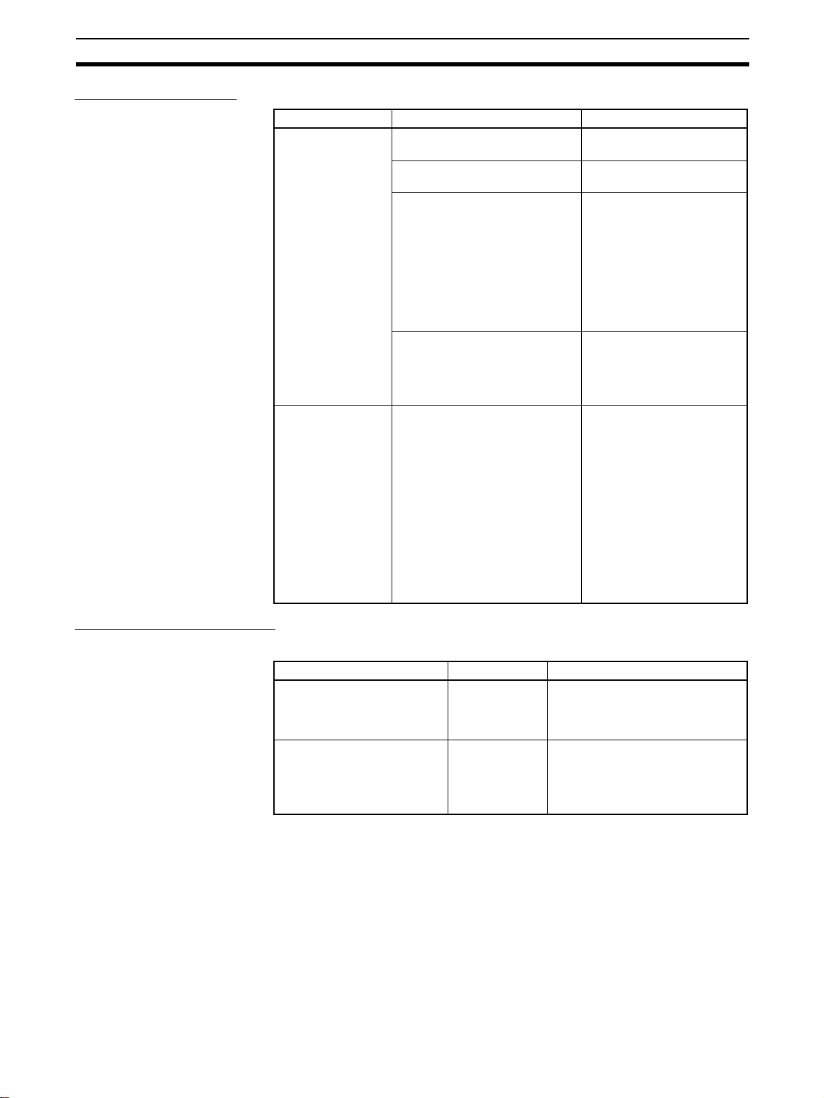
Configuration Devices Section 2-2
Rack Configurations
Name Configuration Remarks
CS1D Expansion
Racks
CS1D Long-distance Expansion
Racks
CS1D Online Replacement
Expansion Backplane
CS1D Power Supply Units Two Units (or one) are
Duplex CPU, Dual I/O Expansion
System
• Mount a CS1D-IC102D I/O
Control Unit to the CS1D CPU
Rack.
• Mount CS1D-II102D I/O Interface Units to the CS1D Expansion Racks.
• A terminator is not required.
CS-series Connecting Cable
(When CS1D CPU Rack + CS1D
Expansion Racks are connected)
Mount an I/O Control Unit
(CS1W-IC102) to the CS1D CPU
Rack.
Mount an I/O Interface Unit
(CS1W-II102) to each Long-distance Expansion Rack.
Attach a Terminator (CV500TER01) to the last Long-distance
Expansion Rack in each series.
Two Terminators are provided
with the I/O Control Unit.
One Backplane is required.
required.
One (or two) CS1D I/O Con-
trol Units or I/O Interface
Units are required.
It is not possible to connect
to either a CS-series Expansion Rack or a C200H
Expansion I/O Rack from a
CS1D Expansion Rack.
Each I/O Control Unit and
I/O Interface Unit requires
one slot.
These Units are not allocated I/O words.
Use CV-series I/O Connecting Cables.
A CS1D Long-distance
Expansion Rack cannot be
connected to another Longdistance Expansion Rack
using CS-series I/O Connecting Cable.
Configuration Device List
CS1D Online Replacement Expansion Backplane
Name Model Specifications
Expansion Backplane supporting online replacement
(for a Duplex CPU, Dual I/O
Expansion System)
CS1D Online Replacement
Expansion Backplane (for a
Duplex CPU Single I/O
Expansion System or Single
CPU System)
CS1D-BI082D Duplex Connecting Cables: 7 slots
Single Connecting Cable: 8 slots
CS1D-BI092 9 slots
Used for both CS1D Expansion
Racks and CS1D Long-distance
Expansion Racks.
39
Page 76

Configuration Devices Section 2-2
CS1D Power Supply Units Two CS1D Power Supply Units are required for a duplex configuration.
Name Model Specifications
CS1D Power Supply
Units
CS1D I/O Interface Unit
Name Model Specifications
CS1D I/O Interface Unit (for a
Duplex CPU, Dual I/O Expansion System)
CS-series Connecting Cables
Name Model Specifications Remarks
CS-series
Connecting Cables
CS1D-PA207R 100 to 120 V AC or 200 to 240 V AC
CS1D-PD024 24 V DC
CS1D-PD025 24 V DC
CS1D-II102D One or two Units are required for a
CS1W-CN313
(See note.)
CS1W-CN713
(See note.)
CS1W-CN223 2 m
CS1W-CN323 3 m
CS1W-CN523 5 m
CS1W-CN133 10 m
CS1W-CN133B2 12 m
(RUN output)
Output capacity: 5 V DC, 7 A; 26 V DC,
1.3 A
Output capacity: 5 V DC at 4.3 A;
26 V DC at 0.56 A
Output capacity: 5 V DC at 5.3 A;
26 V DC at 1.3 A
Duplex CPU, Dual I/O Expansion
System.
Connects between CS1D
CPU Racks or CS1D Expansion Racks.
0.3 m
0.7 m
Note When using a CS1W-CN313 or CS1W-CN713 CS-series I/O Expansion
Cable for a CS1D System, always use a Cable manufactured on or after September 20, 2001. The manufacturing date is indicated on the connector as a
4-digit code or a 6-digit code. Cables that were manufactured before this date,
or that do not indicate a manufacturing date cannot be used.
Manufacturing Date Codes
4-digit Code
Ye a r
(e.g., 8 for 1998, 1 for 2001)
Month (1 to 9, X, Y, Z)
Day (01 to 31)
6-digit Code
Factory code
(A to Z, or blank)
Day (01 to 31)
Month (01 to 12)
Year (E.g., 02 for 2002)
40
Page 77

Configuration Devices Section 2-2
Devices for Long-distance Expansion Racks
Name Model Specifications Remarks
I/O Control Unit CS1W-IC102 Mounts to the leftmost slot
on the CS1D CPU Rack to
enable connecting CS1D
Long-distance Expansion
Racks.
I/O Interface Unit CS1W-II102 Mounts to the leftmost slot
CV-series I/O Connecting Cables
CV500-CN312 Connects CS1D Long-disCV500-CN612 0.6 m
CV500-CN122 1 m
CV500-CN222 2 m
CV500-CN322 3 m
CV500-CN522 5 m
CV500-CN132 10 m
CV500-CN232 20 m
CV500-CN332 30 m
CV500-CN432 40 m
CV500-CN532 50 m
on a Long-distance Expansion Rack.
tance Expansion Racks.
---
0.3 m
Connectable Units The following table shows the Units that can be connected to CS1D CPU
Racks and CS1D Expansion Racks.
Rack Unit
Basic I/O Units (See note 1.) Special I/O Units CPU Bus
CS-series
Basic I/O
Units
CS1D CPU Racks Ye s No No Ye s No Ye s
CS1D Expansion
Racks
CS1D Long-dis-
tance Expansion
Racks
Ye s No No Ye s No Ye s
Ye s No No Ye s No Ye s
C200H Basic
I/O Units
C200H Group
2 Multi-point
I/O Units
CS-series
Special I/O
Units
C200H
Special I/O
Units
Units
CPU Bus
Units
(See note 2.)
Note 1. Interrupt Input Units can be used only as ordinary Input Units.
2. Although CPU Bus Units can be mounted, it is not recommended because
of delays in cycle time.
Maximum Number of
Connectable Units
The maximum number of expansion slots depends upon the system configuration, as shown in the following table. The total number of each type of Unit is
not limited by the mounting location.
Note Up to 16 CPU Bus Units can be mounted.
System Max. number of slots
Duplex CPU, Dual I/O
Expansion System
Duplex CPU, Single I/O Expansion System 68 slots
Single CPU System 71 slots
Duplex Connecting Cables 52 slots
Single Connecting Cable 60 slots
41
Page 78

Configuration Devices Section 2-2
CS1D Configuration
Devices
Name Model Support Remarks
CPU
Units
Duplex
Unit
Power
Supply
Units
CPU
Backplanes
CPU Units for
Duplex CPU
Systems
CPU Units for
Single CPU
Systems
CS-series CPU
Units
Duplex CPU,
Dual I/O Expansion System
Duplex CPU,
Single I/O
Expansion System
CS1D Power
Supply Units
C200H and CSseries Power
Supply Units
CPU Backplane
for Duplex CPU
Systems
CPU Backplane
for Single CPU
Systems
CS-series CPU
Backplanes
The following table shows the Units, Programming Devices, and Support Software that can be used to configure a CS1D Duplex System.
Note Always use the specified CS1D Units for the CPU Units, Power Supply Units,
CPU Backplanes, and Expansion Backplanes. CS-series Units cannot be
used.
Duplex CPU,
Dual I/O
Expansion
System
CS1D-CPU@@H
CS1D-CPU@@P
CS1D-CPU@@S No No Ye s
CS1G/H-CPU@@-V1
CS1G/H-CPU@@H
CS1D-DPL02D Ye s No No ---
CS1D-DPL01 No Ye s No ---
CS1D-PA207R
CS1D-PD024
CS1D-PD025
C200HW-P@@@@@ No No No
CS1D-BC042D
(for a Duplex CPU,
Dual I/O Expansion
System)
CS1D-BC052 (See
note.)
(for a Duplex CPU,
Single I/O Expansion
System)
CS1D-BC082S No No Ye s
CS1W-BC@@@ No No No
Ye s
(Unit version
1.3 or later)
No No No
Ye s Ye s Ye s Use specified CS1D Units
Ye s No No Use specified CS1D Units
No Ye s No
Duplex CPU,
Single I/O
Expansion
System
Ye s No Use specified CS1D Units
Single
CPU
System
only.
CS-series Units cannot be
used.
only.
C200H and CS-series Units
cannot be used.
only.
CS-series Units cannot be
used.
Note When securing the
Expansion Rack's
cable, the Backplane
must have a production date of July 2005
or later.
42
Page 79

Configuration Devices Section 2-2
Name Model Support Remarks
Duplex CPU,
Dual I/O
Expansion
System
Expansion
Backplanes
CS1D I/O Control Unit CS1D-IC102D Ye s No No Use with a Duplex CPU, Dual
CS1D I/O Interface Unit CS1D-II102D Ye s No No Use with a Duplex CPU, Dual
I/O Control Unit CS1W-IC102 No Ye s Ye s Use with a Long-distance
I/O Interface Unit CS1W-II102 No Ye s Ye s Use with the Long-distance
Terminator CV500-TER01 No Ye s Ye s Use for terminating resis-
Expansion Rack Cable
Mounting Bracket
Online Replacement Expansion Backplane
CS-series
Expansion
Backplanes
C200H Expansion Backplanes
CS1D-BI082D
(for a Duplex CPU,
Dual I/O Expansion
System)
CS1D-BI092
(for a Duplex CPU,
Single I/O Expansion
System or Single
CPU System)
CS1W-BI@@@ No No No
C200HW-BI@@@-V1 No No No
CS1D-ATT01 No Ye s No Secures the Connecting
CS1D-ATT02 Ye s No No Secures the Connecting
Ye s No No Use specified CS1D Units
No Ye s Ye s
Duplex CPU,
Single I/O
Expansion
System
Single
CPU
System
only.
CS-series Units cannot be
used.
CS1D Expansion Racks and
CS1D Long-distance Expansion Racks can both be
used. The Connecting Cable
is the same as that used for
the CS Series.
Note When securing the
Expansion Rack's
cable, the Backplane
must have a production date of July 2005
or later.
I/O Expansion System.
(Mount in the CPU Rack.
Cannot be mounted in an
Expansion Rack.)
I/O Expansion System.
(Mount in the Expansion
Racks. Cannot be mounted
in the CPU Rack.)
Expansion Rack (Mount to
the CPU Backplane. Cannot
be mounted to an Expansion
Backplane.)
Expansion Rack. (Cannot be
mounted to an Expansion
Rack.)
tance on the Long-distance
Expansion Rack.
Cable in a Duplex CPU, Dual
I/O Expansion System.
Cable in a Duplex CPU, Single I/O Expansion System.
43
Page 80

Configuration Devices Section 2-2
Name Model Support Remarks
Duplex
CPU
System
Basic I/O Units CS-series Basic I/O Units Ye s Ye s ---
CS1W-INT01 CS-series
Interrupt Input Units
C200H Basic I/O Units No No C200H I/O Units cannot be used.
Special I/O Units CS-series Special I/O
CPU Bus Units CS-series CPU Bus Units
Inner Boards CS1W-SBC21
Memory Cards HMC-EF@@@ Ye s Ye s --Battery Set CS1W-BAT01 Ye s Ye s --Connector Covers C500-COV01 Ye s Ye s Use to protect the power supply con-
Space Units CS1W-SP001 Ye s Ye s Mount to an unused I/O slot.
Programming
Devices
and Support Software
CSseries
Connecting
Cables
Software for
personal computer
Programming
Console
0.3 m CS1W-CN313 Ye s Ye s Use to connect between Expansion
0.7 m CS1W-CN713 Ye s Ye s
2 m CS1W-CN223 Ye s Ye s
3 m CS1W-CN323 Ye s Ye s
5 m CS1W-CN523 Ye s Ye s
10 m CS1W-CN133 Ye s Ye s
12 m CS1W-CN133-B2 Ye s Ye s
Units
C200H Special I/O Units No No C200H Special I/O Units cannot be
(including Communications Units that support
duplex operation)
CS1W-SCB21-V1
CS1W-SCB41
CS1W-SCB41-V1
CS1W-LCB01/05 (See
note.) and other models
CV500-COV01 Ye s Ye s Use to protect the I/O slot connector
CS1D-SP001 Ye s Ye s Mount to an unused Power Supply
CS1D-SP002 Ye s Ye s Mount to an unused Power Supply
CX-Programmer Ver. 4.0
or higher
CX-Programmer Ver. 3.0
or higher
CX-Programmer Ver. 2.1
or higher
CX-Protocol Ye s Ye s --SYSMAC-CPT No No --SYSMAC Support Soft-
ware (SSS)
CQM1-PRO01 Ye s Ye s The Key Sheet and Connecting
CQM1H-PRO01 Ye s Ye s --C200H-PRO27 Ye s Ye s ---
Restricted Ye s Can be used only as Standard I/O
Ye s Ye s ---
Ye s Ye s ---
No Ye s Inner Boards cannot be used in
Ye s Ye s ---
Ye s No Use Ver. 3.1 or higher for online Unit
No No ---
No No ---
Single
CPU
System
Units in Duplex CPU Systems.
used.
Duplex CPU Systems unless built
into a Process-control CPU Unit.
Note Loop Control Board unit ver-
sion 1.5 or later must be used.
nector on the Backplane.
on the Backplane.
Unit slot (same shape as PA207R).
Unit slot (same shape as PD024).
replacement functions.
Cable are the same as those used for
the CS1/CS1-H System.
Racks or between Expansion Rack
and CPU Rack.
44
Page 81

Duplex Unit Section 2-3
Name Model Support Remarks
Longdistance
Expansion
Cables
Duplex
CPU
System
0.3 m CV500-CN312 Ye s Ye s Use to connect Long-distance
0.6 m CV500-CN612 Ye s Ye s
1 m CV500-CN122 Ye s Ye s
2 m CV500-CN222 Ye s Ye s
3 m CV500-CN322 Ye s Ye s
5 m CV500-CN522 Ye s Ye s
10 m CV500-CN132 Ye s Ye s
20 m CV500-CN232 Ye s Ye s
30 m CV500-CN332 Ye s Ye s
40 m CV500-CN432 Ye s Ye s
50 m CV500-CN532 Ye s Ye s
Single
CPU
System
Expansion Racks.
2-3 Duplex Unit
2-3-1 Duplex Unit Model
Item Specifications
Model number CS1D-DPL02D (for a Duplex CPU, Dual I/O Expansion System)
CS1D-DPL01 (for a Duplex CPU, Single I/O Expansion System)
Number mounted One Duplex Unit is required for a Duplex CPU System.
Weight 200 g max.
One Duplex Unit is required for a Duplex CPU System. It is not required for a
Single CPU System.
45
Page 82

Duplex Unit Section 2-3
2-3-2 Nomenclature
DPL STATUS (Green/Red)
Displays duplex status (green) and duplex
error status (red).
L/CPU STATUS (Green/Red)
Displays the operation mode (RUN,
MONITOR, or PROGRAM) of the left
CPU Unit, or duplex initialization in progress, and operation switching error (red).
R/CPU STATUS (Green/Red)
Displays the operation mode (RUN,
MONITOR, or PROGRAM) of the right
CPU Unit, or duplex initialization in progress, and operation switching error (red).
DPL SW
Duplex Setting Switches
DPL/SPL
Duplex/Simplex Mode setting
ACT. RIGHT/ACT. LEFT
Sets whether the active CPU Unit will be on
the right or the left side.
SW
Communications Setting Switch
Sets communications conditions.
DPL02D CS
DPL STATUS
ACTIVE
L
CPU STATUS
ACTIVE
R
CPU STATUS
LEFT CPU
RIGHT CPU
DPL SW
ON
INIT.
SW
ON
DPL
USE
NO USE
USE
NO USE
ON OFF
SPL
ACT.
LEFT
PRPHL
COMM
A39512
RSV
USE
NO USE
DPL
ACT.
RIGHT
L/ACTIVE CPU (Green)
ON when active CPU Unit is on the left.
R/ACTIVE CPU (Green)
ON when active CPU Unit is on the right.
LEFT CPU
Left CPU Operation Setting Switch
To turn OFF the power to the left CPU while
it is mounted, set this switch to NO USE.
RIGHT CPU
Right CPU Operation Setting Switch
To turn OFF the power to the right CPU while
it is mounted, set this switch to NO USE.
INIT
Initial Switch
Enables the Mode Setting Switch (DPL/SPL).
DPL (CS1D-DPL02D Only)
Duplex Operation Setting Switch
To turn OFF the power to the Duplex Unit
while it is mounted, set this switch to NO USE.
Duplex Unit Switches
!Caution Before touching the Duplex Unit, be sure to first touch grounded metal to dis-
CPU Operating Switches
charge static electricity.
LEFT CPU
USE
NO USE
Setting Contents Application
USE Turns ON power to
CPU Unit.
NO USE Turns OFF power to
CPU Unit.
RIGHT CPU
USE
NO USE
Turns ON or OFF the
power supply to the
respective CPU
Units.
Set to NO USE when
replacing a CPU Unit
while leaving the power
ON, or when not using a
CPU Unit.
46
Page 83

Duplex Unit Section 2-3
Duplex Unit Operating
Switch
Duplex Setting Switches
DPL
USE
NO USE
Setting Contents Application
USE Turns ON power to
the Duplex Unit.
NO USE Turns OFF power to
the Duplex Unit.
Turns ON or OFF the
power supply to the
Duplex Unit.
Set to NO USE when
replacing a Duplex Unit.
while leaving the power
ON.
The Duplex CPU System will operate in Simplex Mode during
replacement.
DPL SW
ON
ON
SPL
ACT.
LEFT
OFF
DPL
ACT.
RIGHT
(1) Mode Setting Switch (DPL/SPL)
Switch Setting Meaning Application
DPL/SPL OFF DPL Duplex
Mode
ON SPL Simplex
Mode
Sets whether the System will
operate in Duplex Mode or Simplex Mode.
This switch is enabled in the following situations:
1) When the power is turned ON.
2) When the CPU Operation Setting Switch is switched from NO
USE to USE.
3) When the Initial Switch is
pressed.
Note: Switching is disabled during operation. This switch is also
disabled in a Simplex System.
Set to OFF
(DPL) for Duplex
Mode, and to
ON (SPL) for
Simplex Mode.
Note Duplex Mode and Simplex Mode can also be determined by the status of bit
08 of word A328.
(2) Active Setting Switch (ACT. RIGHT/ACT. LEFT)
Switch Setting Contents Application
ACT
RIGHT/
ACT
LEFT
OFF ACT
RIGHT
ON ACT
LEFT
Sets the right
CS1D CPU Unit
as the active
Unit.
Sets the left
CS1D CPU Unit
as the active
Unit.
Sets whether the right
or left CS1D CPU Unit
is to be the active Unit.
This switch is enabled
only when the power is
turned ON, so, after
changing the setting,
turn the power OFF
and then back ON
again.
Changing the setting
is disabled during
operation. This switch
is also disabled in
Simplex Mode.
To set the right
CS1D CPU Unit
as the active
Unit, set the
switch to OFF
(ACT RIGHT).
To set the left
CS1D CPU Unit
as the active
Unit, set the
switch to ON
(ACT LEFT).
47
Page 84

Duplex Unit Section 2-3
Initial Switch
Press the Initial Switch to toggle between Duplex Mode and Simplex Mode
after a CS1D CPU Unit has been replaced.
INIT.
Setting Contents Application
Communications Setting
Switch
The Mode Setting
Switch is enabled
when this switch is
pressed.
Note If the Initial Switch is pressed immediately after the power supply is turned
ON, it may not have any effect.
SW
PRPHL
COMM
A39512
ON
RSV
In place of pins 4, 5, and 6 of the DIP switches on the right and left CPU Units,
set the PRPHL and COMM pins and bit A39512 as shown in the following
table.
Turn OFF pins 4, 5, and 6 on both the right and left CPU Units.
Reflects the status
(Duplex/Simplex Mode) of the
Mode Setting Switch while the
power is ON.
Press to return to Duplex
Mode after a CS1D CPU Unit
has been replaced.
If there is no change in the
Mode Setting Switch, then the
mode (Duplex/Simplex) will
not be changed even if the Initial Switch is pressed.
Pin Contents Setting Applications
PRPHL Peripheral port
communications
(In place of pin 4
of the DIP
switches.)
COMM RS-232C commu-
nications conditions
(In place of pin 5
of the DIP
switches.)
A39512 User-customized
DIP switch pin
(In place of pin 6
of the DIP
switches.)
RSV Dis-
ON According to the peripheral port baud
OFF
(default)
ON Connect a CX-Programmer at the
OFF
(default)
ON A39512 ON The status of this DIP switch pin is
OFF
(default)
abled
rate setting in the PLC Setup. (See
note 3.)
Connect a Programming Console or
CX-Programmer at the baud rate for
Programming Devices. (The communications conditions are automatically
detected.) (See note 1.)
baud rate for Programming Consoles.
(The baud rate is automatically
detected.) (See note 2.)
According to the RS-232C port communications conditions settings in the
PLC Setup.
A39512 OFF
Set to OFF.
Leave OFF when peripheral port is to
be used by a Programming Console
or CX-Programmer (with peripheral
bus setting).
Turn ON when peripheral port is to be
used by other than a Programming
Console or CX-Programmer (peripheral bus).
Leave OFF when RS-232C port is to
be used by other than a CX-Programmer (peripheral bus), such as a PT or
host computer.
Turn ON when RS-232C port is to be
used by a CX-Programmer (peripheral bus).
reflected in the User DIP Switch Pin
Flag (A39512) in the Auxiliary Area.
Note 1. The order of automatic detection looks for a Programming Console first
and then it will attempt to detect a peripheral bus connect at the following
speeds: 9,600 bps, 19,200 bps, 38,400 bps, and then 115,200 bps. If the
Programming Device is in a mode other than peripheral bus, or if it is set
48
Page 85

Duplex Unit Section 2-3
by peripheral bus to a baud rate other than those that are automatically detected, the auto-detection function will not work.
2. The order of automatic detection is as follows: 9,600 bps, 19,200 bps,
38,400 bps, and then 115,200 bps. If the Programming Device is in a mode
other than peripheral bus, or if it is set by peripheral bus to a baud rate other than those that are automatically detected, the auto-detection function
will not work.
3. For details on the PLC Setup, refer to SECTION 6 PLC Setup.
4. When connecting a CX-Programmer to the peripheral port or RS-232C
port, set the CX-Programmer’s network classification and either the
PRPHL pin or the COMM pin on the DIP switch as shown in the following
table.
CX-Programmer’s
network setting
Peripheral bus Set the PRPHL
SYSWAY (Host Link) Set the PRPHL
5. Be sure to set the RSV (reserve) pin to OFF.
Connecting to
peripheral port
pin to OFF.
pin to ON.
Connecting to
RS-232C port
Set the COMM pin
to ON.
Set the COMM pin
to OFF.
PLC Setup
---
Set to “Host Link.”
49
Page 86

Duplex Unit Section 2-3
Duplex Unit Indicators
DPL01 CS
DPL STATUS
ACTIVE
L
CPU STATUS
ACTIVE
R
CPU STATUS
Indicator Status Contents Description
DPL STATUS Green
(ON)
Green
(flashing)
Red
Green
Red (ON) A duplex bus error has
Red
(flashing)
OFF The System is operating
The System is operating
normally in Duplex Mode.
The System is being initialized for duplex operation.
occurred in the System.
A duplex verification error
has occurred in the System.
normally in Simplex Mode.
The active and standby CPU Units are operating
normally in synchronization in Duplex Mode.
The active and standby CPU Units are being initialized for duplex operation (transferring or verifying data).
A duplex bus error has occurred in Duplex
Mode. (An error has occurred in the duplex bus,
and A31601 has turned ON.)
Note At this time, the mode is switched from
Duplex Mode to Simplex Mode, and
operation is continued by the active CPU
Unit alone.
A duplex verification error has occurred in
Duplex Mode. (One of the following items does
not match for the active and standby CPU Units,
and A31600 has turned ON.)
CPU Unit model numbers
Parameter Areas
User program areas
Inner Board data is not the same (Process-control CPU Units only).
A function not supported by the standby CPU
Unit was performed by the active CPU Unit (unit
version 1.1 or later).
The cause of the duplex verification error is
stored in Auxiliary Area word A317.
Note
1. At this time, the mode is switched from Duplex Mode to Simplex Mode, and operation
is continued by the active CPU Unit alone.
2. Verification is not performed for the mounting, model number, or data contents of
Memory Cards, or for front-panel DIP switch
settings. Operation will continue in Duplex
Mode even if these do not match for the active and standby CPU Units.
Either operation is normal in Simplex Mode, or
an error has occurred in Duplex Mode and the
System is now operating normally in Simplex
Mode.
50
Page 87

Duplex Unit Section 2-3
Indicator Status Contents Description
L ACTIVE Green
(ON)
OFF The left CPU Unit is on
Green
CPU STATUS Green
(ON)
Green
(flashing)
Red
Green
Red (ON) Operation
Red
(flashing)
OFF The left CPU Unit is in PRO-
The left CPU Unit is active
(ACT).
standby (STB).
The left CPU Unit is in RUN
or MONITOR Mode.
The left CPU Unit is being
initialized for duplex operation, or the CPU Unit is waiting.
CPU error A CPU error has occurred at the left CPU Unit.
switching
error at the
left CPU Unit
GRAM Mode.
Other than
CPU error
The left CPU Unit is the active (i.e., controlling)
CPU Unit.
Either the left CPU Unit is on standby or the
CPU Unit has stopped.
The left CPU Unit is operating (i.e., in RUN or
MONITOR Mode).
Either the left CPU Unit is being initialized for
duplex operation (transferring or verifying duplex
data) or the CPU Unit is waiting.
While this indicator is flashing, neither of the
CPU Units will begin operation.
Note
1. If “Run Under Duplex Initial” in the PLC Setup is set to “Start running during initialization” only the active CPU Unit will start
running during duplex initialization.
2. This indicator will flash even if a duplex bus
error or a duplex verification error occurs
when the power is turned ON.
One of the following operation switching errors
has occurred at the left CPU Unit.
Memory error
Program error
Cycle time overrun error
FALS instruction executed
Fatal Inner Board error (Process-control CPU
Units only)
The left CPU Unit is in PROGRAM Mode, or a
fatal error other than those indicated by a lit or
flashing red indicator has occurred.
51
Page 88

Duplex Unit Section 2-3
Indicator Status Contents Description
R ACTIVE Green
(ON)
OFF The right CPU Unit is on
Green
CPU STATUS Green
(ON)
Green
(flashing)
Red
Green
Red (ON) Operation
Red
(flashing)
OFF The right CPU Unit is in
The right CPU Unit is active
(ACT).
standby (STB).
The right CPU Unit is in
RUN or MONITOR Mode.
The right CPU Unit is being
initialized for duplex operation, or the CPU is waiting.
CPU error A CPU error has occurred at the right CPU Unit.
switching
error at the
right CPU
Unit
PROGRAM Mode.
Other than
CPU error
The right CPU Unit is the active (i.e., controlling)
CPU Unit.
Either the right CPU Unit is on standby or the
CPU Unit is stopped.
The right CPU Unit is operating (i.e., in RUN or
MONITOR Mode).
Either the right CPU Unit is being initialized for
duplex operation (transferring or verifying duplex
data) or the CPU is waiting.
While this indicator is flashing, neither of the
CPU Units will begin operation.
Note
1. If “Run Under Duplex Initial” in the PLC Setup is set to “Start running during initialization” only the active CPU Unit will start
running during duplex initialization.
2. This indicator will flash even if a duplex bus
error or a duplex verification error occurs
when the power is turned ON.
One of the following operation switching errors
has occurred at the right CPU Unit.
Memory error
Program error
Cycle time overrun error
FALS instruction executed
Fatal Inner Board error (Process-control CPU
Units only)
The right CPU Unit is in PROGRAM Mode, or a
fatal error other than those indicated by a lit or
flashing red indicator has occurred.
Indicator Status when
Power Is Turned ON
The following table shows the status of Duplex Unit indicators when the power
supply is turned ON. In this example, the left (L) CPU Unit is set as the active
one (ACT.LEFT).
Duplex Unit indicators Status at startup
Being initialized (transferring
data, e.g., user program
immediately after startup)
DPL STATUS Green (flashing) Green (ON) Green (ON) OFF
L (Active) ACTIVE Green (ON) Green (ON) Green (ON) Green (ON)
CPU STATUS Green (flashing) OFF Green (ON) Green (ON)
R (Non-active) ACTIVE OFF OFF OFF OFF
CPU STATUS Green (flashing) OFF Green (ON) OFF
In PROGRAM
Mode
Operating in
Duplex Mode
Operating in
Simplex Mode
Note The items set in bold text in the table are the main ones to indicate the status.
52
Page 89

Duplex Unit Section 2-3
Indicator Status when
Errors Occur
The following table shows the status of Duplex Unit indicators when errors
occur during Duplex Mode operation (i.e., in either RUN Mode or MONITOR
Mode). In this example, the left (L) CPU Unit is set as the active one
(ACT.LEFT).
Duplex Unit indicators Error status
Operation switching
error at active CPU
Unit
Non- CPU
error
CPU
error
DPL STATUS OFF Green (ON) Red
L (When
set to
active)
R (When
set to
standby)
ACTIVE OFF Green (ON) Green (ON) Green (ON) Green (ON)
CPU STATUS Red
Red (ON) OFF Green (flashing)
(flashing)
ACTIVE Green (ON) OFF OFF OFF OFF
CPU STATUS Green (ON)
(See note 1.)
Fatal error at
active CPU
Unit (e.g., too
many I/O
points)
Duplex error Non-fatal
active CPU
Duplex
verifica-
tion error
(flashing)
Duplex
bus
error
Red
(ON)
Green (ON) Green (flash-
CPU waiting
error at
Unit
ing)
Green (ON) Green (flash-
(See note 2.)
ing)
OFF OFF Green (ON) Green (flash-
ing)
System operation Continues. Stops. Continues. Continues. Waits.
Note 1. If operation is switched to the standby CPU Unit (i.e., in this example, from
the left CPU Unit to the right), and then an error occurs at the newly active
CPU Unit, the CPU STATUS indicator will flash red for a non-CPU error and
stay lit red for a CPU error.
2. This indicator will light green if a duplex error occurs during operation.
3. The items set in bold text in the table are the main ones to indicate the status.
Indicator Status when
Replacing the Duplex
Unit Online
(CS1D-DPLO2D Only)
When the Duplex Unit Operating Switch (DPL USE/NO USE) is set to NO
USE to replace the Duplex Unit online, all of the Duplex Unit indicators will be
OFF (not lit). During online replacement, only the active CPU Unit will continue operating.
2-3-3 External Dimensions
DPL01
DPL STATUS
ACTIVE
L
CPU STATUS
ACTIVE
R
CPU STATUS
LEFT CPU
USE
NO USE
RIGHT CPU
USE
NO USE
DPL SW
OFF
ON
130
DPL
SPL
ACT.
ACT.
RIGHT
LEFT
ON
INIT.
SW
PRPHL
COMM
A39512
RSV
ON
DUPLEX
34.5
100.51.2
124
22.3 (Backplane)
53
Page 90

CPU Units Section 2-4
2-4 CPU Units
2-4-1 Models
CPU Units for Duplex CPU
Systems
CPU Units for Single CPU
Systems
Number of I/O
points (Number
of Expansion
Racks)
5,120 points
(7 Racks)
960 points
(2 Racks)
1,280 points
(3 Racks)
5,120 points
(7 Racks)
5,120 points
(7 Racks)
Programming Data Memory
(DM + EM)
250 Ksteps 448 Kwords CS1D-CPU67H 350 g max.
60 Ksteps 128 Kwords CS1D-CPU65H
10 Ksteps 64 Kwords CS1D-CPU42S
30 Ksteps 64 Kwords CS1D-CPU44S
60 Ksteps 128 Kwords CS1D-CPU65S
250 Ksteps 448 Kwords CS1D-CPU67S
Model Weight
54
Page 91

CPU Units Section 2-4
2-4-2 Components
Inner Board
Connector
Install an Inner
Board. (See note.)
Peripheral Port
Connects
Programming
Device (including
Programming
Console) host
computer, etc.
Refer to 2-6.
RS-232C Port
Connects CXProgrammer (but not
Programming
Console), host
computer, external
devices,
Programmable
Terminal (PT), etc.
Refer to 2-6.
RUN
ERR/ALM
INH
BKUP
PRPHL
COMM
SYSMAC
CS1D-CPU67H
PROGRAMMABLE CONTROLLER
OPE
N
BUSYMCPWR
PERIPHERAL
PORT
Memory Card
Connector
Memory Card
Install into the active CPU Unit.
Memory Card
Powered/Accessed Indicators
MCPWR (ON: green)
Power provided to Memory
Card.
BUSY (ON: Yellow)
Memory Card being accessed.
Memory Card Power Supply
Button
Press this button to turn OFF
the power supply before
removing the Memory Card or
when performing the simple
backup operation.
Memory Card Eject Button
Press to remove the Memory
Card.
RUN
Lit green when the CPU Unit is
operating normally in MONITOR or
RUN mode.
ERR/ALM
Lit read when a fatal error was
discovered in self-diagnosis or a
hardware error has occurred. The CPU
Unit will stop operating and all outputs
will be turned OFF.
Flashing red when a non-fatal error
was discovered in self-diagnosis.
The CPU Unit will continue operating.
INH
Lit yellow when the Output OFF Bit
(A50015) has been turned ON. The
outputs from all Output Units will turn
OFF.
BKUP
Lit yellow when data is being
transferred between RAM and flash
memory.
Do not turn OFF the power supply to
the PLC while this indicator is lit.
PRPHL
Flashes yellow when the CPU Unit is
communicating (sending or receiving)
via the peripheral port.
Note: An Inner Board can be
mounted in a Single CPU System.
Note In a Duplex CPU System, the DIP switch on the front panel of the active CPU
COMM
View with battery housing opened.
Flashes yellow when the CPU Unit is
communicating (sending or receiving)
via the RS-232C port.
MCPWR
Lit green when power is being supplied
to the Memory Card.
BUSY
Flashes yellow when the Memory Card
DIP Switch
is being accessed.
Pin 1: User program memory write (enable: OFF; disable: ON)
Pin 2: Automatic user program transfer at startup (not transferred: OFF; transferred: ON)
Pin 3: Always OFF.
Pin 4:
Pin 5: Refer to
DIP Switch Settings.
Pin 6:
Pin 7:
Easy backup (read/write from Memory Card) with pin 7 ON and pin 8 OFF.
Easy backup (verification with Memory Card) with pin 7 OFF and pin 8 OFF.
Pin 8: Always OFF.
Unit is enabled (and the one on the standby CPU Unit is disabled). The DIP
switch settings on the active and standby CPU Units do not necessarily have
to match. Even if they do not match, operation in Duplex Mode is still possible.
55
Page 92

CPU Units Section 2-4
Indicators
RUN
ERR/ALM
INH
BKUP
COMM
PRPHL
Indicator Color Status Meaning
RUN Green ON CPU Unit is operating normally in MONITOR or RUN
mode.
Flashing DIP switch settings error.
OFF PLC has stopped operating while in PROGRAM
mode, or has stopped operating due to a fatal error.
ERR/ALM Red ON A fatal error has occurred (including FALS instruction
Flashing A non-fatal error has occurred (including FAL instruc-
OFF CPU Unit is operating normally.
INH Ye l l o w ON Output OFF Bit (A50015) has been turned ON. The
OFF Output OFF Bit (A50015) has been turned OFF.
BKUP Ye l l o w ON User program and Parameter Area data is being
OFF Data is not being written to flash memory.
PRPHL Ye l l o w Flashing CPU Unit is communicating (sending or receiving)
OFF CPU Unit is not communicating via the peripheral
COMM Ye l l o w Flashing CPU Unit is communicating (sending or receiving)
OFF CPU Unit is not communicating via the RS-232C
execution), or a hardware error (CPU error) has
occurred.
The CPU Unit will stop operating, and the outputs will
turn OFF.
tion execution).
The CPU Unit will continue operating.
outputs from all Output Units will turn OFF.
backed up to flash memory in the CPU Unit or being
restored from flash memory.
Do not turn OFF the power supply to the PLC while
this indicator is lit.
via the peripheral port.
port.
via the RS-232C port.
port.
56
Page 93

CPU Units Section 2-4
BUSYMCPWR
OPEN
PERIPHERAL
Indicator Color Status Meaning
MCPWR Green ON Power is being supplied to the Memory
Card.
Flashing Flashes once: Simple backup write, read, or
OFF Power is not being supplied to the Memory
BUSY Ye l l o w Flashing Memory Card is being accessed.
OFF Memory Card is not being accessed.
verify normal.
Flashes five times: Simple backup read
error.
Flashes three times: Simple backup read
warning.
Flashes continuously: Simple backup write
or verify error.
Card.
DIP Switch Settings A Duplex CPU System, the DIP switch on the front panel of the active CPU
Unit is enabled (and the one on the standby CPU Unit is disabled). The DIP
switch settings on the active and standby CPU Units do not necessarily have
to match. (A duplex verification error will not be generated.) Even if they do
not match, operation in Duplex Mode is still possible.
ON
8 7 6 5 4 3 2 1
Pin No. Setting Function Application Default
1 ON Writing prohibited for user program
memory. (See note 1.)
OFF Writing enabled for user program
memory.
2 ON The user program is automatically
transferred from the Memory Card
when power is turned ON. (See
note 2.)
OFF The user program is not automati-
cally transferred from the Memory
Card when power is turned ON.
3 Always OFF. Use with this pin set to OFF. --- OFF
4 to 6 See below. ---
Used to prevent programs from being accidently
overwritten from Programming Devices (including Programming Console).
Used to store the programs in the Memory Card
for switching operations, or to automatically
transfer programs at startup (Memory Card ROM
operation).
Note When pin 7 is ON and pin 8 is OFF, sim-
ple backup reading from the Memory
Card is given priority, so even if pin 2 is
ON, the user program is not automatically
transferred from the Memory Card when
power is turned ON.
OFF
OFF
57
Page 94

CPU Units Section 2-4
Pin No. Setting Function Application Default
7 Simple backup type Used to determine the simple backup type. (See
8 Always OFF. --- --- OFF
note 3.)
Normally turn this pin OFF.
DIP Switch Pins 4 to 6 Set these pins as described below. Settings are different for Duplex CPU and
Single CPU Systems.
■ Duplex CPU Systems
Pin No. Setting Function Application Default
4 Always OFF. Use with this pin set to OFF. Do not set these switches. Instead, use the
5 Always OFF. Use with this pin set to OFF. OFF
6 Always OFF. Use with this pin set to OFF. OFF
PRPHL and COMM switches on the Duplex Unit
and A39512 in the Auxiliary Area.
■ Single CPU Systems
Pin No. Setting Function Application Default
4 ON Peripheral port communications
parameters set in the PLC Setup
are used.
OFF Peripheral port communications
parameters set using Programming
Console or CX-Programmer
(Peripheral bus only) are used.
5 ON RS-232C port communications
parameters set using a CX-Programmer (Peripheral bus only) are
used.
OFF RS-232C port communications
parameters set in the PLC Setup
are used.
6 ON User-defined pin. Turns OFF the
User DIP Switch Pin Flag (A39512).
OFF User-defined pin. Turns ON the
User DIP Switch Pin Flag (A39512).
Turn ON to use the peripheral port for a device
other than Programming Console or CX-Programmer (Peripheral bus only).
Turn ON to use the RS-232C port for a Programming Device.
Set pin 6 to ON or OFF and use A39512 in the
program to create a user-defined condition without using an I/O Unit.
OFF
OFF
OFF
OFF
OFF
58
!Caution Always touch a grounded metal object to discharge static electricity from your
body before changing the settings on the DIP switch during operation.
Note 1. When pin 1 is set to ON, writing is prohibited for the user program and all
parameter data (PLC Setup, I/O table registration, etc.). Moreover, it is not
possible to clear the user program or parameters even by executing a
memory clear operation from a Programming Device.
2. In a Duplex CPU System, automatic transfer at startup can be executed
only from the active CPU Unit. Duplex initialization is performed between
the two CPU Units after the automatic transfer, and the user program, parameters, and I/O memory are matched. If pin 2 it set to ON, I/O memory
(AUTOEXEC.IOM, ATEXEC@@.IOM) will also be transferred automatically. (Refer to the Programming Manual.) The program (AUTOEXEC.OBJ)
and Parameter Area (AUTOEXEC.STD) must both be on the Memory
Card, but the I/O memory (AUTOEXEC.IOM, ATEXEC@@.IOM) does not
need to be.
3. Simple Backup Operations
In Duplex Mode, the simple backup function can be executed only from the
active CPU Unit. Duplex initialization is not executed between the two CPU
Page 95

CPU Units Section 2-4
Units after simple backup is performed. Therefore, after the data has been
read to the CPU Unit, turn the power OFF and back ON and then press the
Initial Switch on the Duplex Unit. If DIP switch pin 7 on the active CPU Unit
is ON, a duplex verification error will occur.
Pin 7 of DIP switch
on CPU Unit
ON Writing from active CPU Unit
OFF (default) Comparison of Memory
Note After data is read from the Memory Card to the CPU Unit using the
simple backup function, operation is not possible in any mode other
than PROGRAM Mode. To switch to either MONITOR Mode or
RUN Mode, first turn the power OFF and turn DIP switch pin 7 back
OFF.
Then turn the power back ON and change the mode from a Programming Device.
Simple backup operation Procedure
Hold down the Memory
to Memory Card
Reading from Memory Card
to active CPU Unit
Card and CPU Unit
Card Power Supply Switch
for three seconds.
Turn PLC power OFF and
then back ON.
This setting is given priority
over automatic transfer at
startup (pin 2 ON).
Hold down the Memory
Card Power Supply Switch
for three seconds.
2-4-3 CPU Unit Memory Map
The memory of CS1D CPU Units is configured in the following blocks.
• I/O Memory: The data areas accessible from the user program
• User Memory: The user program and Parameter Area (See note 1.)
The above memory is backed up using a CS1W-BAT01 Battery. If the battery
voltage is low, the data in these areas will not be stable.
The CPU Unit has a built-in flash memory, however, to which the user program and Parameter Area data is backed up whenever the user memory is
written to, including data transfers and online editing from a Programming
Device (CX-Programmer or Programming Console, data transfers from a
Memory Card, etc.). The user program and the Parameter Area data will thus
not be lost even if battery voltage drops.
59
Page 96

CPU Units Section 2-4
CPU Unit
Built-in RAM
I/O Memory Area
Flash Memory
User program
Parameter Area
Written
automatically
Written
automatically
Backup
Drive 1: EM file
memory (See note 2.)
User program
Drive 0: Memory
Card
(flash memory)
Parameter Area
(See note 1.)
Automatically backed up to flash memory whenever
a write operation for the user program or parameter
area is performed from a Programming Device.
File memory
Battery
The battery life is 5 years at an
ambient temperature of 25°C.
Note 1. The Parameter Area stores system information for the CPU Unit, such as
the PLC Setup.
2. Part of the EM (Extended Data Memory) Area can be converted to file
memory to handle data files and program files in RAM memory format,
which has the same format as Memory Cards. File memory in the EM Area
is backed up by a battery.
60
Page 97

CPU Units Section 2-4
p
2-4-4 Battery Compartment and Peripheral Port Covers
Opening the Battery
Compartment Cover
Insert a small flat-blade screwdriver into the opening at the bottom of the battery compartment cover and lift open the cover.
Insert a small flat-blade
screwdriver into the opening
at the bottom of the battery
compartment cover and lift
open the cover.
Battery
DIP switch
Opening the Peripheral Port Cover and Connecting Cables
Insert a small flat-blade
screwdriver into the
opening at the top of the
ort cover and pull open.
Make sure the connector is
in facing the correct direction.
Hold the grips on the side of the
connector and push into the port.
61
Page 98

File Memory Section 2-5
2-4-5 Dimensions
2-5 File Memory
71
RUN
ERR/ALM
INH
PRPHL
SYSMAC
CS1D-CPU67H
PROGRAMMABLE CONTROLLER
OPEN
MCPWR
OPEN
PERIPHERAL
PORT
BUSY
BKUP
COMM
130 134
104.3
100.5
(Backplane) 22.3
For CS1D CPU Units, the Memory Card and a specified part of the EM Area
can be used to store files. All user programs, the I/O Memory Area, and the
Parameter Area can be stored as files.
File memory Memory
Memory Card
(See note 3.)
type
Flash
memory
Memory capacity Model
30 Mbytes HMC-EF372
64 Mbytes HMC-EF672
128 Mbytes HMC-EF183
62
EM file memory
Bank 0
Bank n
Bank C
EM file
memory
RAM The maximum capac-
ity of the CPU Unit’s
EM Area (e.g., the
maximum capacity for
a CPU67 is
832 Kbytes)
The specified bank
(set in the PLC Setup)
to the last bank of the
EM Area in the I/O
Memory.
Note 1. A Memory Card can be written up to approximately 100,000 times. (Each
write operation to the Memory Card must be counted regardless of the size
of the write.) Be particularly careful not to exceed the service life of the
Memory Card when writing to it from the ladder program.
2. The HMC-AP001 Memory Card Adapter is shown below.
3. For precautions regarding the use of Memory Cards, refer to 5-1 File Mem-
ory in the SYSMAC CS/CJ/NSJ Series Programmable Controllers Programming Manual (W394).
Page 99

File Memory Section 2-5
2-5-1 File Memory Functions in Duplex CPU Systems
Only the Memory Card in the active CPU Unit is accessed, whereas EM file
memory is accessed for both the active and standby CPU Units.
Using Memory Cards
Operation in a Duplex CPU
System
Memory Card functions can be executed in duplex only when the doing so is
enabled in the PLC Setup. In Duplex Mode, the same data that is written to
the Memory Card mounted in the active CPU Unit will also be written to the
Memory Card in the standby CPU Unit. No processing, however, is executed
during duplex initialization to match the data on the Memory Cards mounted
in the active and standby CPU Units. Therefore, before enabling duplex operation for Memory Cards, make sure that the contents are the same for both of
the Memory Cards.
Data read from the Memory Card mounted in the active CPU Unit is used by
both the active and standby CPU Units, so this ensures that the data for the
two CPU Units will match.
Memory Card Functions The following table shows the operations of the various Memory Card-related
functions.
Function Memory Card location Data unification
Installed
in active
CPU Unit
Writing to Memory
Card using the
FWRIT instruction
Reading from Memory Card using the
FREAD instruction
Automatic transfer
when power is
turned ON
Replacement of the
Entire Program During Operation
Simple backup Duplex operation is not ini-
Accessed. Accessed.
Installed
in standby
CPU Unit
(Same
data written as for
active CPU
Unit.)
Not
accessed.
processing method
Data is written to the Memory Cards mounted in both
CPU Units.
Data read from the Memory
Card in the active CPU Unit
is used by both CPU Units.
After the automatic transfer
at startup, duplex initialization is executed between the
two CPU Units, and the user
program, parameters, and
I/O memory are matched.
Simultaneously with program replacement during
operation, duplex operation
is initialized between the two
CPU Units, and the user programs are matched.
tialized between the CPU
Units after reading to the
CPU Units.
When referencing file memory-related
status, use the status for the active CPU
Unit (word A343).
There is no need to mount a Memory
Card or to set the DIP switch at the
standby CPU Unit.
After data is read from the Memory Card
by the simple backup operation, the CPU
Unit will be in PROGRAM mode. (CSseries specifications)
To begin the operation:
1. Turn OFF the power and set DIP
switch pins 7 and 8 on the CPU Units.
Then turn the power back ON.
2. Press the Initial Switch on the Duplex
Unit.
Note If pin 7 on the active CPU Unit is
turned ON, a duplex verification
error will be generated.
Notes
63
Page 100

File Memory Section 2-5
Note For details, refer to the CS/CJ-series Programming Manual.
Using EM File Memory
Operation in a Duplex CPU
System
When a file is written to the EM file memory in the active CPU Unit in a Duplex
System, the same file is simultaneously written to the EM file memory in the
standby CPU Unit.
Note If EM file memory is specified for the active CPU Unit’s EM Area with the PLC
Setup, the same banks will be specified for the standby CPU Unit’s EM Area
by means of duplex initialization.
EM File Memory-related
Functions
Function EM file memory Data matching method Note
In active
CPU Unit
Writing to EM file
memory by FWRIT
instruction
Reading from EM file
memory by FREAD
instruction
Accessed. Accessed When a file is written to the active CPU
The following table shows the operations of the EM file memory-related functions.
In standby
CPU Unit
When referencing file mem-
Not
accessed.
Unit’s EM file memory, the file is simultaneously written to the standby CPU
Unit’s EM file memory. FWRIT instruction execution is synchronized for the
active and standby CPU Units.
The FREAD instruction is executed for
both CPU Units, and the data read
from the active CPU Unit’s EM file
memory is used by both CPU Units.
ory-related status, use the
status for the active CPU Unit
(word A343).
2-5-2 Files Handled by CPU Unit
General-use Files
Files Transferred
Automatically at Startup
Files are ordered and stored in the Memory Card or EM file memory according to the file name and the extension attached to it. File names handled by
the CPU Unit (i.e., file names that can be read) are set as shown in the following tables.
File type Contents File name Extension
Data files Specified range in I/O
memory
Program files All user programs ∗∗∗∗∗∗∗∗ .OBJ
Parameter files PLC Setup, registered I/O tables,
routing tables, CPU Bus Unit settings, SYSMAC LINK link tables, and
Controller Link link tables
File type Contents File name
Data files DM Area data (stores data for
specified number of words starting
from D20000)
DM Area data (stores data for
specified number of words starting
from D00000)
EM area for bank No. @ (stores
data for specified number of words
starting from E@_00000)
Binary ∗∗∗∗∗∗∗∗ .IOM
Te xt .TXT
CSV .CSV
∗∗∗∗∗∗∗∗ .STD
AUTOEXEC .IOM
ATEXECDM .IOM
ATEXECE@
(EM bank No.)
.IOM
64
 Loading...