Omron CR-UGD4-XXL1300H User Manual

Cat. No. I201E-EN-03

Delta 3+1 Robot IP65 protection class

CR_UGD4_XXL1300H Series

USER´S MANUAL

CONTENTS

Safety Instructions

1.Attention

2.Explanation of warnings and notes

3.Safety information

3.1General

3.2Qualified personnel

3.3Liability

3.4Installation and operating conditions

3.5Residual risks

3.5.1Release device

3.5.2Transport

3.5.3Assembly and start-up

3.5.4Maintenance and repair

3.5.5System integrator

CR_UGD4_XXL1300H

User's Manual

S-1

S-1

S-2

S-2

S-2

S-2

S-2

S-2

S-3

S-3

S-3

S-3

S-4

Chapter 1

Introduction


1.

Introduction

1-1

1.1

Description of the robot

1-1

1.2

Type code explanation

1-1


2.

Identification

1-1


3.

Part names


1-2


Chapter 2

Model overview


1.

Overview


2-1


Chapter 3

Installation


1.

Unpacking


3-1

1.1

Unpacking the shipping box

3-1

1.2

Check the damage

3-1

1.3

Lifting and transportation

3-1


2.

Mounting the robot

3-3


3.

Mounting the motors and cabling

3-4

3.1

Mounting the motors

3-4

3.2

Connecting the cables

3-4

3.3

Mounting the motor covers

3-5

3.4

Mounting the rotation motor or gearbox with his adaptor ring

3-6

T-1

CONTENTS

CR_UGD4_XXL1300H

User's Manual

4.

Assembling the secondary arms

3-7

4.1

Make an assembly

3-7

4.2

Mount the arm assembly on the robot

3-8


5.

Mounting the rotational axis on the gearbox shaft

3-9


6.

Calibration


3-10


7.

Gripper interface

3-11

7.1

With rotational axis

3-11

7.2

Without rotational axis

3-12


Chapter 4

Maintenance


1.

Periodic maintenance

4-1

1.1

Springs


4-1

1.2

Ball bearing cups

4-2

1.3

Rotational axis

4-2


2.

Cleaning the robot

4-4


3.

Spare parts


4-4


Chapter 5

Robot settings


1.

Kinematics


5-1


2.

Workspace


5-2


3.

Software limits

5-3


Chapter 6

Specifications


1.

Basic specifications

6-1

1.1

Cycle time


6-1


2.

External view and dimensions

6-2


3.

External view and dimensions (Robots with serial number 4042 or lower)

6-3


4.

Design specifications

6-4

4.1

Occupation area of robot

6-4

4.2

Software design

6-5


4.2.1 Dimensions and limits

6-6

T-2

Safety Instructions

Contents

1.


Attention

S-1


2.

Explanation of warnings and notes

S-1


3.


Safety information

S-2

3.1

General

S-2

3.2

Qualified personnel

S-2

3.3

Liability

S-2

3.4

Installation and operating conditions

S-2

3.5

Residual risks

S-2

3.5.1

Release device

S-3

3.5.2

Transport

S-3

3.5.3

Assembly and start-up

S-3

3.5.4

Maintenance and repair

S-3

3.5.5

System integrator

S-4

1.Attention

Information in this document can change without prior notice.

OMRON EUROPE B.V. cannot be hold responsible for any damage to the environment, to the machine or to the functioning of the machine occurred by errors or missing data in the illustrations, drawing or specifications.

No part of this manual and added documentation may be copied, reproduced or translated into another language without prior written approval.

Read and understand the material contained in this user's manual before you work on the CR_UGD4_XXL1300H robot for the first time. This user's manual is supposed to help you use the capabilities of the CR_UGD4_XXL1300H robot safely and properly.

2.Explanation of warnings and notes

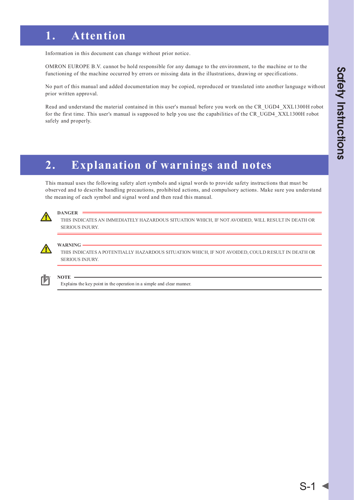
This manual uses the following safety alert symbols and signal words to provide safety instructions that must be observed and to describe handling precautions, prohibited actions, and compulsory actions. Make sure you understand the meaning of each symbol and signal word and then read this manual.

DANGER

THIS INDICATESAN IMMEDIATELYHAZARDOUS SITUATION WHICH, IF NOTAVOIDED, WILLRESULT IN DEATH OR SERIOUS INJURY.

WARNING

THIS INDICATESAPOTENTIALLYHAZARDOUS SITUATION WHICH, IF NOTAVOIDED, COULD RESULT IN DEATH OR SERIOUS INJURY.

NOTE

Explains the key point in the operation in a simple and clear manner.

<![if ! IE]>

<![endif]>Instructions Safety

S-1

<![if ! IE]>

<![endif]>Instructions Safety

3.Safety information

3.1General

This ´3. Safety information´ subchapter contains information regarding working with the CR_UGD4_XXL1300H robot. Qualified personnel working with the CR_UGD4_XXL1300H robot must have read and understood the CR_ UGD4_XXL1300H robot documentation, including the safety information chapter.

3.2Qualified personnel

These are people who, due there specialist training, knowledge and experience, and their familiarization with the relevant standards, are able to assess the work to be carried out and detect any potential hazards.

3.3Liability

The CR_UGD4_XXL1300H robot is build using state-of-the-art technology and in accordance with the recognized safety rules. Nevertheless, misuse of the CR_UGD4_XXL1300H robot may constitute a risk to life and limb or cause damage to the CR_UGD4_XXL1300H robot and to other material property.

3.4Installation and operating conditions

You may only use the components in accordance with the installation and operating conditions described in the documentation. The operating conditions at the installation location must be checked and maintained in accordance with the required technical data. Within the meaning of the Machinery Directive the CR_UGD4_XXL1300H robot is an incomplete machine. Commissioning is prohibited until the usable machine or system in which the CR_UGD4_ XXL1300H robot is installed meets all requirements of the Machine directive 2006/42/EC.

For the CR_UGD4_XXL1300H robot you have to observe the following standards, directives and regulations:

EN ISO 10218-1:2011 Robots and robotic devices - Safety requirements for industrial robots - Part 1: Robots.

EN ISO 10218-1:2011 Robots and robotic devices - Safety requirements for industrial robots - Part 2: Robot systems and integration.

3.5Residual risks

Safety and health risks arising from the robot mechanics have been reduced by means of safety technology and design engineering. However a residual risk remains, since the robot mechanics will be move by an automated control system.

The following are typical warnings concerning residual risks which cannot be assigned to a specific action. The expression of safety labels is identical to the safety information.

S-2

3.5.1Release device

The robot mechanics are not supplied with an release switch to control the brakes of the motors.

WARNING

• MOUNTARELEASE SWITCH ON THE MACHINE SO THEARMS (MOTOR) OF THE ROBOT COULD BE MANUALLY

MOVED.

MOVINGANAXIS WITHAN IMPROPERLYWORKING RELEASE SWITCH CAN DAMAGE THE MOTOR BRAKE. THIS CAN RESULT IN PERSONALINJURYAND MATERIALDAMAGE.

BEFORE RELEASING THE BRAKE,YOU HAVE TO BE SURE THAT NO ONE IS IN THE HAZARDAREAOF THE ROBOT.

3.5.2Transport

The prescribed transport position of the robot must be observed. Transportation must be carried out in accordance with the transportation instructions or assembly instructions of the robot.

WARNING

• ONLYUSEAUTHORIZED HANDLING EQUIPMENTWITHASUFFICIENT LOAD-BEARING CAPACITYTO TRANSPORT THE ROBOT.

WEAR SUITABLE PROTECTIVE CLOTHING IF NECESSARY.

3.5.3Assembly and start-up

Before starting up systems and devices for the first time, a check must be carried out to ensure that the system and devices are completed and operational, that they can be operated safely and that any damage is detected.

The valid national or regional work safety regulations must be observed for this check. The correct functioning of all safety circuits must also be tested.

The following tests must be carried out before start-up and recommissioning. It must be ensured that:

The robot is correctly installed and fastened in accordance with the specifications in the assembly instructions.

There are no foreign bodies or loose parts on the robot.

All required safety equipment is correctly installed and operational.

WARNING

• AWRONG INSTALLED ROBOT MAYTHROW OFF HISARMS.

WEAR SUITABLE PROTECTIVE CLOTHING IF NECESSARY.

3.5.4Maintenance and repair

After maintenance and repair work, checks must be carried out to ensure the required safety level. The valid national or regional work safety regulations must be observed for this check. The correct functioning of all safety circuits must also be tested.

The purpose of maintenance and repair work is to ensure that the system is kept original or, in the event of a fault, to return the system to an operational state. Repair work includes troubleshooting in addition to the actual repair itself.

The following safety measures must be carried out when working on the robot:

Switch of the machine (system) where the robot is built-in (e.g. with a padlock) to prevent it from being switched on again

Label the machine (system) with a sign indication that work is in progress. This sign must remain in place, even during temporary interruptions to the work.

The emergency stop from the machine (system) must remain active. If safety functions or safeguards are deactivated during maintenance or repair work, they must be reactivated immediately after the work is completed.

<![if ! IE]>

<![endif]>Instructions Safety

S-3

<![if ! IE]>

<![endif]>Instructions Safety

3.5.5System integrator

The robot is safely integrated into a complete system by the system integrator. The system integrator is responsible for the following tasks:

Installing the robot

Performing risk assessment

Implementing the required safety functions and safequards

Issuing the declaration of conformity

Attaching the CE mark

Creating the operating instructions for the complete system

S-4

Chapter 1 Introduction


Contents


1.

Introduction

1-1


1.1 Description of the robot

1-1


1.2

Type code explanation

1-1


2.

Identification

1-1


3.

Part names

1-2


1.Introduction

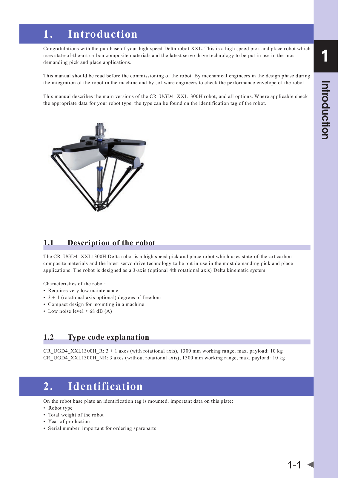
Congratulations with the purchase of your high speed Delta robot XXL. This is a high speed pick and place robot which uses state-of-the-art carbon composite materials and the latest servo drive technology to be put in use in the most demanding pick and place applications.

This manual should be read before the commissioning of the robot. By mechanical engineers in the design phase during the integration of the robot in the machine and by software engineers to check the performance envelope of the robot.

This manual describes the main versions of the CR_UGD4_XXL1300H robot, and all options. Where applicable check the appropriate data for your robot type, the type can be found on the identification tag of the robot.

1.1Description of the robot

The CR_UGD4_XXL1300H Delta robot is a high speed pick and place robot which uses state-of-the-art carbon composite materials and the latest servo drive technology to be put in use in the most demanding pick and place applications. The robot is designed as a 3-axis (optional 4th rotational axis) Delta kinematic system.

Characteristics of the robot:

Requires very low maintenance

3 + 1 (rotational axis optional) degrees of freedom

Compact design for mounting in a machine

Low noise level < 68 dB (A)

1.2Type code explanation

CR_UGD4_XXL1300H_R: 3 + 1 axes (with rotational axis), 1300 mm working range, max. payload: 10 kg CR_UGD4_XXL1300H_NR: 3 axes (without rotational axis), 1300 mm working range, max. payload: 10 kg

2.Identification

On the robot base plate an identification tag is mounted, important data on this plate:

Robot type

Total weight of the robot

Year of production

Serial number, important for ordering spareparts

1

<![if ! IE]>

<![endif]>Introduction

1-1

Omron CR-UGD4-XXL1300H User Manual

1

<![if ! IE]>

<![endif]>Introduction

3.Part names

CR_UGD4_XXL1300H

Cable entry plate

Rotary servo motor

Motor cover


Primary arm

Rotational axis

Secondary arm

TCP (Tool Center Point)

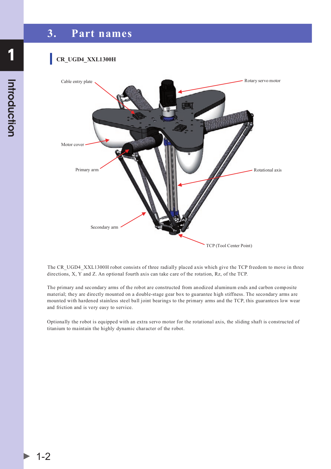
The CR_UGD4_XXL1300H robot consists of three radially placed axis which give the TCP freedom to move in three directions, X, Y and Z. An optional fourth axis can take care of the rotation, Rz, of the TCP.

The primary and secondary arms of the robot are constructed from anodized aluminum ends and carbon composite material; they are directly mounted on a double-stage gear box to guarantee high stiffness. The secondary arms are mounted with hardened stainless steel ball joint bearings to the primary arms and the TCP, this guarantees low wear and friction and is very easy to service.

Optionally the robot is equipped with an extra servo motor for the rotational axis, the sliding shaft is constructed of titanium to maintain the highly dynamic character of the robot.

1-2

Chapter 2 Model overview

Contents

1. Overview

2-1

1.Overview

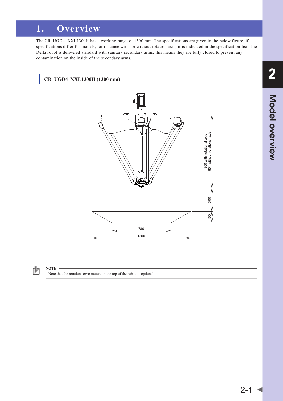
The CR_UGD4_XXL1300H has a working range of 1300 mm. The specifications are given in the below figure, if specifications differ for models, for instance withor without rotation axis, it is indicated in the specification list. The Delta robot is delivered standard with sanitary secondary arms, this means they are fully closed to prevent any contamination on the inside of the secondary arms.

CR_UGD4_XXL1300H (1300 mm)

<![if ! IE]>

<![endif]>900 with rotational axis 851 without rotational axis

<![if ! IE]>

<![endif]>150 300

780

1300

NOTE

Note that the rotation servo motor, on the top of the robot, is optional.

2

<![if ! IE]>

<![endif]>overview Model

2-1

Loading...
+ 39 hidden pages