

Page 1

Cat.No. W365–E1–1
SYSMAC CQM1H Series
CQM1H-SCB41
Serial Communications Board
OPERATION MANUAL
Page 2

SYSMAC
CQM1H Series
CQM1H-SCB41
Serial Communications Board
Operation Manual
Produced September 1999
Page 3

Notice:
OMRON products are manufactured for use according to proper procedures by a qualified operator
and only for the purposes described in this manual.
The following conventions are used to indicate and classify precautions in this manual. Always heed
the information provided with them. Failure to heed precautions can result in injury to people or damage to property.
DANGER Indicates an imminently hazardous situation which, if not avoided, will result in death or
!
serious injury.
WARNING Indicates a potentially hazardous situation which, if not avoided, could result in death or
!
serious injury.
Caution Indicates a potentially hazardous situation which, if not avoided, may result in minor or
!
moderate injury, or property damage.
OMRON Product References
All OMRON products are capitalized in this manual. The word “Unit” is also capitalized when it refers
to an OMRON product, regardless of whether or not it appears in the proper name of the product.
The abbreviation “Ch,” which appears in some displays and on some OMRON products, often means
“word” and is abbreviated “Wd” in documentation in this sense.
The abbreviation “PC” means Programmable Controller and is not used as an abbreviation for anything else.
Visual Aids
The following headings appear in the left column of the manual to help you locate different types of
information.
OMRON, 1999
All rights reserved. No part of this publication may be reproduced, stored in a retrieval system, or transmitted, in any
form, or by any means, mechanical, electronic, photocopying, recording, or otherwise, without the prior written permission of OMRON.
No patent liability is assumed with respect to the use of the information contained herein. Moreover, because OMRON is
constantly striving to improve its high-quality products, the information contained in this manual is subject to change
without notice. Every precaution has been taken in the preparation of this manual. Nevertheless, OMRON assumes no
responsibility for errors or omissions. Neither is any liability assumed for damages resulting from the use of the information contained in this publication.
Note Indicates information of particular interest for efficient and convenient operation
of the product.
1, 2, 3... 1. Indicates lists of one sort or another, such as procedures, checklists, etc.
v
Page 4

About this Manual:
This manual describes the installation and operation of the SYSMAC CQM1H-series CQM1H-SCB41 Serial Communications Board and includes the sections described below.
The Serial Communications Board is classified as an Inner Board.
Read this manual and all related manuals listed in the following table carefully and be sure you understand
the information provided before attempting to install and operate a Serial Communications Board.
Name Cat. No. Contents
SYSMAC CQM1H-series
CQM1H-SCB41
Serial Communications Board
Operation Manual
SYSMAC CQM1H-series
Programmable Controllers
Operation Manual
SYSMAC CQM1H-series
Programmable Controllers
Programming Manual
SYSMAC WS02-PSTC1-E
CX-Protocol Operation Manual
W365-E1-1 Describes the use of the Serial Communications Board to
perform serial communications with external devices,
including hardware and the usage of standard system
protocols for OMRON products.
Host Link communications commands are described in the
SYSMAC CQM1H-series Programmable Controllers
Programming Manual (W364).
Creating protocol macros is described in the CX-Protocol
Operation Manual (W344).
W363-E1-1 Describes the installation and operation of the
CQM1H-series PCs.
W364-E1-1 Describes the ladder diagram programming instructions
supported by CQM1H-series PCs, Host Link commands,
and other programming information.
W344-E1-1 Describes the use of the CX-Protocol to create protocol
macros as communications sequences to communicate with
external devices.
Section 1 introduces the hardware and software functions of the Serial Communications Board, including
the serial communications modes, system configurations, and specifications.
Section 2 describes the components of the Serial Communications Board, how to connect it in the CPU
Unit, and how to connect it to external devices.
Section 3 describes the settings, control bits, flags, and status information available in the CPU Unit for
use with the Serial Communications Board.
Section 4 describes the procedure and other information required to use Host Link communications.
Section 5 describes the procedure and other information required to use protocol macros.
Section 6 provides information required to use no-protocol communications on a Serial Communications
Board port.
Section 7 provides information required to create 1:1 data links through a Serial Communications Board
port.
Section 8 describes the procedure and other information required to use 1:N-mode and 1:1-mode NT
Links to Programmable Terminals (PTs).
Section 9 describes the troubleshooting and maintenance procedures for the Serial Communications
Boards.
Appendix A to Appendix N provide the specifications of the standard system protocols.
!
WARNING Failure to read and understand the information provided in this manual may result in
personal injury or death, damage to the product, or product failure. Please read each
section in its entirety and be sure you understand the information provided in the section
and related sections before attempting any of the procedures or operations given.
vii
Page 5

TABLE OF CONTENTS
PRECAUTIONS xi. . . . . . . . . . . . . . . . . . . . . . . . . . . . . . . . .
1 Intended Audience xii. . . . . . . . . . . . . . . . . . . . . . . . . . . . . . . . . . . . . . . . . . . . . . . . . . . . . . . . . . .
2 General Precautions xii. . . . . . . . . . . . . . . . . . . . . . . . . . . . . . . . . . . . . . . . . . . . . . . . . . . . . . . . . .
3 Safety Precautions xii. . . . . . . . . . . . . . . . . . . . . . . . . . . . . . . . . . . . . . . . . . . . . . . . . . . . . . . . . . .
4 Operating Environment Precautions xiii. . . . . . . . . . . . . . . . . . . . . . . . . . . . . . . . . . . . . . . . . . . . .
5 Application Precautions xiii. . . . . . . . . . . . . . . . . . . . . . . . . . . . . . . . . . . . . . . . . . . . . . . . . . . . . .
6 Conformance to EC Directives xv. . . . . . . . . . . . . . . . . . . . . . . . . . . . . . . . . . . . . . . . . . . . . . . . .
SECTION 1
Introduction 1. . . . . . . . . . . . . . . . . . . . . . . . . . . . . . . . . . . .
1-1 Overview 2. . . . . . . . . . . . . . . . . . . . . . . . . . . . . . . . . . . . . . . . . . . . . . . . . . . . . . . . . . . . . .
1-2 Protocol Overview 4. . . . . . . . . . . . . . . . . . . . . . . . . . . . . . . . . . . . . . . . . . . . . . . . . . . . . . .
1-3 Specifications 8. . . . . . . . . . . . . . . . . . . . . . . . . . . . . . . . . . . . . . . . . . . . . . . . . . . . . . . . . . .
1-4 Basic Operating Procedure 8. . . . . . . . . . . . . . . . . . . . . . . . . . . . . . . . . . . . . . . . . . . . . . . . .
SECTION 2
Board Components and Installation 9. . . . . . . . . . . . . . . . .
2-1 Component Names and Functions 10. . . . . . . . . . . . . . . . . . . . . . . . . . . . . . . . . . . . . . . . . . .
2-2 Installation 14. . . . . . . . . . . . . . . . . . . . . . . . . . . . . . . . . . . . . . . . . . . . . . . . . . . . . . . . . . . . .
2-3 Wiring 17. . . . . . . . . . . . . . . . . . . . . . . . . . . . . . . . . . . . . . . . . . . . . . . . . . . . . . . . . . . . . . . . .
SECTION 3
Default Settings and Related Bits/Flags 27. . . . . . . . . . . . . .
3-1 Overview 28. . . . . . . . . . . . . . . . . . . . . . . . . . . . . . . . . . . . . . . . . . . . . . . . . . . . . . . . . . . . . .
3-2 PC Setup Settings 28. . . . . . . . . . . . . . . . . . . . . . . . . . . . . . . . . . . . . . . . . . . . . . . . . . . . . . . .
3-3 Control Bits, Flags, and Status Information 30. . . . . . . . . . . . . . . . . . . . . . . . . . . . . . . . . . .
SECTION 4
Host Link Communications 33. . . . . . . . . . . . . . . . . . . . . . .
4-1 Host Link Communications 34. . . . . . . . . . . . . . . . . . . . . . . . . . . . . . . . . . . . . . . . . . . . . . . .
4-2 Application Procedure 36. . . . . . . . . . . . . . . . . . . . . . . . . . . . . . . . . . . . . . . . . . . . . . . . . . . .
4-3 Connections 39. . . . . . . . . . . . . . . . . . . . . . . . . . . . . . . . . . . . . . . . . . . . . . . . . . . . . . . . . . . .
4-4 Host Link Communications 45. . . . . . . . . . . . . . . . . . . . . . . . . . . . . . . . . . . . . . . . . . . . . . . .
4-5 Changes from Previous Products 53. . . . . . . . . . . . . . . . . . . . . . . . . . . . . . . . . . . . . . . . . . . .
SECTION 5
Protocol Macros 57. . . . . . . . . . . . . . . . . . . . . . . . . . . . . . . . .
5-1 Overview of the Protocol Macro Functions 58. . . . . . . . . . . . . . . . . . . . . . . . . . . . . . . . . . . .
5-2 Restrictions in Using the CX-Protocol 65. . . . . . . . . . . . . . . . . . . . . . . . . . . . . . . . . . . . . . . .
5-3 Application Procedure 66. . . . . . . . . . . . . . . . . . . . . . . . . . . . . . . . . . . . . . . . . . . . . . . . . . . .
5-4 Connections 70. . . . . . . . . . . . . . . . . . . . . . . . . . . . . . . . . . . . . . . . . . . . . . . . . . . . . . . . . . . .
5-5 Protocol Structure 76. . . . . . . . . . . . . . . . . . . . . . . . . . . . . . . . . . . . . . . . . . . . . . . . . . . . . . . .
5-6 Control Bits, Flags, and Status Information 80. . . . . . . . . . . . . . . . . . . . . . . . . . . . . . . . . . .
5-7 Using Protocol Macros 85. . . . . . . . . . . . . . . . . . . . . . . . . . . . . . . . . . . . . . . . . . . . . . . . . . . .
SECTION 6
No-protocol Communications 97. . . . . . . . . . . . . . . . . . . . . .
6-1 Overview 98. . . . . . . . . . . . . . . . . . . . . . . . . . . . . . . . . . . . . . . . . . . . . . . . . . . . . . . . . . . . . .
6-2 Application Procedure 100. . . . . . . . . . . . . . . . . . . . . . . . . . . . . . . . . . . . . . . . . . . . . . . . . . . .
6-3 Connections 101. . . . . . . . . . . . . . . . . . . . . . . . . . . . . . . . . . . . . . . . . . . . . . . . . . . . . . . . . . . .
6-4 Using No-protocol Communications 102. . . . . . . . . . . . . . . . . . . . . . . . . . . . . . . . . . . . . . . . .
viii
Page 6

TABLE OF CONTENTS
SECTION 7
Communications for 1:1 Data Links 107. . . . . . . . . . . . . . . .
7-1 Overview 108. . . . . . . . . . . . . . . . . . . . . . . . . . . . . . . . . . . . . . . . . . . . . . . . . . . . . . . . . . . . . .
7-2 Application Procedure 109. . . . . . . . . . . . . . . . . . . . . . . . . . . . . . . . . . . . . . . . . . . . . . . . . . . .
7-3 Connections 110. . . . . . . . . . . . . . . . . . . . . . . . . . . . . . . . . . . . . . . . . . . . . . . . . . . . . . . . . . . .
7-4 Using 1:1 Data Links 111. . . . . . . . . . . . . . . . . . . . . . . . . . . . . . . . . . . . . . . . . . . . . . . . . . . . .
SECTION 8
NT Link Communications 113. . . . . . . . . . . . . . . . . . . . . . . . .
8-1 Overview of NT Links 114. . . . . . . . . . . . . . . . . . . . . . . . . . . . . . . . . . . . . . . . . . . . . . . . . . . .
8-2 Application Procedure 116. . . . . . . . . . . . . . . . . . . . . . . . . . . . . . . . . . . . . . . . . . . . . . . . . . . .
8-3 Connections 117. . . . . . . . . . . . . . . . . . . . . . . . . . . . . . . . . . . . . . . . . . . . . . . . . . . . . . . . . . . .
SECTION 9
Troubleshooting and Maintenance 119. . . . . . . . . . . . . . . . . .
9-1 Front-panel Indicator Error Displays 120. . . . . . . . . . . . . . . . . . . . . . . . . . . . . . . . . . . . . . . . .
9-2 Troubleshooting 121. . . . . . . . . . . . . . . . . . . . . . . . . . . . . . . . . . . . . . . . . . . . . . . . . . . . . . . . .
9-3 Cleaning and Inspection 130. . . . . . . . . . . . . . . . . . . . . . . . . . . . . . . . . . . . . . . . . . . . . . . . . . .
9-4 Board Replacement 132. . . . . . . . . . . . . . . . . . . . . . . . . . . . . . . . . . . . . . . . . . . . . . . . . . . . . .
Appendices
A Introduction 135. . . . . . . . . . . . . . . . . . . . . . . . . . . . . . . . . . . . . . . . . . . . . . . . . . . . . . . . . . . . . . .
B CompoWay/F Master Protocol 137. . . . . . . . . . . . . . . . . . . . . . . . . . . . . . . . . . . . . . . . . . . . . . . .
C E5jK Digital Controller Read Protocol 153. . . . . . . . . . . . . . . . . . . . . . . . . . . . . . . . . . . . . . . . . .
D E5jK Digital Controller Write Protocol 171. . . . . . . . . . . . . . . . . . . . . . . . . . . . . . . . . . . . . . . . . .
E E5ZE Temperature Controller Read Protocol 187. . . . . . . . . . . . . . . . . . . . . . . . . . . . . . . . . . . . .
F E5ZE Temperature Controller Write Protocol 209. . . . . . . . . . . . . . . . . . . . . . . . . . . . . . . . . . . . .
G E5jJ Temperature Controller Protocol 229. . . . . . . . . . . . . . . . . . . . . . . . . . . . . . . . . . . . . . . . . . .
H ES100j Digital Controller Protocol 243. . . . . . . . . . . . . . . . . . . . . . . . . . . . . . . . . . . . . . . . . . . . .
I K3Tj Intelligent Signal Processor Protocol 283. . . . . . . . . . . . . . . . . . . . . . . . . . . . . . . . . . . . . . .
J V500/V520 Bar Code Reader Protocol 305. . . . . . . . . . . . . . . . . . . . . . . . . . . . . . . . . . . . . . . . . .
K 3Z4L Laser Micrometer Protocol 317. . . . . . . . . . . . . . . . . . . . . . . . . . . . . . . . . . . . . . . . . . . . . .
L Visual Inspection System Protocol 349. . . . . . . . . . . . . . . . . . . . . . . . . . . . . . . . . . . . . . . . . . . . .
M V600/V620 ID Controller Protocol 367. . . . . . . . . . . . . . . . . . . . . . . . . . . . . . . . . . . . . . . . . . . . .
N Hayes Modem AT Command Protocol 403. . . . . . . . . . . . . . . . . . . . . . . . . . . . . . . . . . . . . . . . . .
Index 411. . . . . . . . . . . . . . . . . . . . . . . . . . . . . . . . . . . . . . . . . .
Revision History 419. . . . . . . . . . . . . . . . . . . . . . . . . . . . . . . . .
ix
Page 7

PRECAUTIONS
This section provides general precautions for using the Serial Communications Boards.
The information contained in this section is important for the safe and reliable application of the Serial Communications Boards and the PC in general. You must read this section and understand the information contained before attempting to set up or operate a PC system containing a Serial Communications Board.
1 Intended Audience xii. . . . . . . . . . . . . . . . . . . . . . . . . . . . . . . . . . . . . . . . . . . . . . . . . . . . . . . . . . . .
2 General Precautions xii. . . . . . . . . . . . . . . . . . . . . . . . . . . . . . . . . . . . . . . . . . . . . . . . . . . . . . . . . . .
3 Safety Precautions xii. . . . . . . . . . . . . . . . . . . . . . . . . . . . . . . . . . . . . . . . . . . . . . . . . . . . . . . . . . . .
4 Operating Environment Precautions xiii. . . . . . . . . . . . . . . . . . . . . . . . . . . . . . . . . . . . . . . . . . . . . .
5 Application Precautions xiii. . . . . . . . . . . . . . . . . . . . . . . . . . . . . . . . . . . . . . . . . . . . . . . . . . . . . . . .
6 Conformance to EC Directives xv. . . . . . . . . . . . . . . . . . . . . . . . . . . . . . . . . . . . . . . . . . . . . . . . . .
6-1 Applicable Directives xv. . . . . . . . . . . . . . . . . . . . . . . . . . . . . . . . . . . . . . . . . . . . . .
6-1-1 Concepts xv. . . . . . . . . . . . . . . . . . . . . . . . . . . . . . . . . . . . . . . . . . . . . . . . . . . . . . . . .
6-1-2 Conformance to EC Directives xv. . . . . . . . . . . . . . . . . . . . . . . . . . . . . . . . . . . . . . .
xi
Page 8

1 Intended Audience
This manual is intended for the following personnel, who must also have knowledge of electrical systems (an electrical engineer or the equivalent).
• Personnel in charge of installing FA systems.
• Personnel in charge of designing FA systems.
• Personnel in charge of managing FA systems and facilities.
2 General Precautions
The user must operate the product according to the performance specifications
described in the operation manuals.
Before using the product under conditions which are not described in the manual
or applying the product to nuclear control systems, railroad systems, aviation
systems, vehicles, combustion systems, medical equipment, amusement machines, safety equipment, and other systems, machines, and equipment that
may have a serious influence on lives and property if used improperly, consult
your OMRON representative.
Make sure that the ratings and performance characteristics of the product are
sufficient for the systems, machines, and equipment, and be sure to provide the
systems, machines, and equipment with double safety mechanisms.
This manual provides information for programming and operating the Unit. Be
sure to read this manual before attempting to use the Unit and keep this manual
close at hand for reference during operation.
3Conformance to EC Directives
WARNING It is extremely important that a Serial Communications Board and all related
!
units be used for the specified purpose and under the specified conditions,
especially in applications that can directly or indirectly affect human life. You
must consult with your OMRON representative before applying a Serial
Communications Board to the above mentioned applications.
3 Safety Precautions
WARNING Never attempt to disassemble any Units while power is being supplied. Doing so
!
may result in electric shock.
WARNING The CPU Unit refreshes I/O even when the program is stopped (i.e., even in
!
PROGRAM mode). Confirm safety thoroughly in advance before changing the
status of any part of memory allocated to I/O Units, Inner Boards, or Dedicated
I/O Units. Any changes to the data allocated to any Unit may result in
unexpected operation of the loads connected to the Unit. Any of the following
operation may result in changes to memory status.
• Transferring I/O memory data to the CPU Unit from a Programming Device.
• Changing present values in memory from a Programming Device.
• Force-setting/-resetting bits from a Programming Device.
• Transferring I/O memory files from a Memory Card or EM file memory to the
CPU Unit.
• Transferring I/O memory from a host computer or from another PC on a network.
xii
WARNING Never touch any of the terminals while power is being supplied. Doing so may
!
result in electric shock.
Caution Execute online edit only after confirming that no adverse effects will be caused
!
by extending the cycle time. Otherwise, input signals may not be read properly.
Page 9

4 Operating Environment Precautions
Caution Do not operate the control system in the following locations:
!
• Locations subject to direct sunlight.
• Locations subject to temperatures or humidity outside the range specified in
the specifications.
• Locations subject to condensation as the result of severe changes in temperature.
• Locations subject to corrosive or flammable gases.
• Locations subject to dust (especially iron dust) or salts.
• Locations subject to exposure to water, oil, or chemicals.
• Locations subject to shock or vibration.
Caution Take appropriate and sufficient countermeasures when installing systems in the
!
following locations:
• Locations subject to static electricity or other forms of noise.
• Locations subject to strong electromagnetic fields.
• Locations subject to possible exposure to radioactivity.
• Locations close to power supplies.
5Conformance to EC Directives
Caution The operating environment of the PC System can have a large effect on the lon-
!
gevity and reliability of the system. Improper operating environments can lead to
malfunction, failure, and other unforeseeable problems with the PC System. Be
sure that the operating environment is within the specified conditions at installation and remains within the specified conditions during the life of the system.
5 Application Precautions
Observe the following precautions when using the PC.
WARNING Failure to abide by the following precautions could lead to serious or possibly
!
fatal injury. Always heed these precautions.
• Always ground the system to 100 Ω or less when installing the system to protect against electrical shock.
• Always turn OFF the power supply to the PC before attempting any of the following. Not turning OFF the power supply may result in malfunction or electric
shock.
• Assembling the Units or mounting the Serial Communications Board.
• Setting DIP switches or rotary switches.
• Connecting or wiring the cables.
• Connecting or disconnecting the connectors.
Caution Failure to abide by the following precautions could lead to faulty operation or the
!
PC or the system or could damage the PC or PC Units. Always heed these precautions.
• Do not turn OFF the power supply while transferring protocol macro data.
• Fail-safe measures must be taken by the customer to ensure safety in the
event of incorrect, missing, or abnormal signals caused by broken signal lines,
momentary power interruptions, or other causes.
xiii
Page 10

• Always discharge static electricity by touching a grounded metal part before
mounting the Serial Communications Board.
• Always discharge static electricity by touching a grounded metal part before
connecting cable connectors to RS-232C or RS-422A/485 port of the Serial
Communications Board.
• Be sure that the connectors, terminal blocks, expansion cables, and other
items with locking devices are properly locked into place. Improper locking
may result in malfunction.
• Confirm that no adverse effect will occur in the system before attempting any of
the following. Not doing so may result in an unexpected operation.
• Changing the operating mode of the PC.
• Force-setting/force-resetting any bit in memory.
• Changing the present value of any word or any set value in memory.
• Take appropriate measures to ensure that the specified power with the rated
voltage and frequency is supplied. Be particularly careful in places where the
power supply is unstable. An incorrect power supply may result in malfunction.
• Leave the label attached to the Unit when wiring. Removing the label may result in malfunction if foreign matter enters the Unit.
5Conformance to EC Directives
• Remove the label after the completion of wiring to ensure proper heat dissipation. Leaving the label attached may result in malfunction.
• Confirm polarities before connecting RS-422A/485 cables. Some devices require that SDA/B and RDA/B or signal polarities be reversed.
• Double-check all wiring and switch settings before turning ON the power supply. Incorrect wiring may result in burning.
• Check the user programming (ladder program, protocol macro data, etc.) for
proper execution before actually running it on the Unit. Not checking the program may result in an unexpected operation.
• Resume operation only after transferring to the new CPU Unit the contents of
the DM Area, HR Area, and other data required for resuming operation. Not
doing so may result in an unexpected operation.
• Circuit boards have sharp or pointed edges, such as those on the leads of electrical parts. Do not touch the back of printed boards or mounted sections with
your bare hands.
• Connect or set terminating resistance correctly when using RS-422A/485
cables.
• During transportation and storage, cover the circuit boards with conductive
materials to prevent them from being damaged by static electricity caused by
LSIs or ICs and keep them within the specified storage temperature.
xiv
• Refer to Section 2 Board Components and Installation and correctly wire and
install the Units.
• Do not attempt to take any Units apart, to repair any Units, or to modify any
Units in any way.
• Disconnect the functional ground terminal when performing withstand voltage
tests. Not disconnecting the functional ground terminal may result in burning.
Page 11

6 Conformance to EC Directives
6-1 Applicable Directives
• EMC Directives
• Low Voltage Directive
6-1-1 Concepts
EMC Directives
OMRON devices that comply with EC Directives also conform to the related
EMC standards so that they can be more easily built into other devices or machines. The actual products have been checked for conformity to EMC standards (see the following note). Whether the products conform to the standards in
the system used by the customer, however, must be checked by the customer.
EMC-related performance of the OMRON devices that comply with EC Directives will vary depending on the configuration, wiring, and other conditions of the
equipment or control panel in which the OMRON devices are installed. The customer must, therefore, perform final checks to confirm that devices and the overall machine conform to EMC standards.
Note Applicable EMC (Electromagnetic Compatibility) standards are as follows:
6Conformance to EC Directives
EMS (Electromagnetic Susceptibility): EN61131-2
EMI (Electromagnetic Interference): EN50081-2
Low Voltage Directive
Always ensure that devices operating at voltages of 50 to 1,000 VAC or 75 to
1,500 VDC meet the required safety standards for the PC (EN61131-2).
6-1-2 Conformance to EC Directives
The CQM1H-series PCs comply with EC Directives. T o ensure that the machine
or device in which a CQM1H-series PC is used complies with EC directives, the
PC must be installed as follows:
1, 2, 3... 1. The PC must be installed within a control panel.
2. Reinforced insulation or double insulation must be used for the DC power
supplies used for the I/O power supplies.
3. PCs complying with EC Directives also conform to the Common Emission
Standard (EN50081-2). When a PC is built into a machine, however, noise
can be generated by switching devices using relay outputs and cause the
overall machine to fail to meet the Standards. If this occurs, surge killers
must be connected or other measures taken external to the PC.
The following methods represent typical methods for reducing noise, and
may not be sufficient in all cases. Required countermeasures will vary
depending on the devices connected to the control panel, wiring, the configuration of the system, and other conditions.
(Radiated emission: 10-m regulations)
6-1-3 EMI Measures
The CQM1H-series PCs conform to the Common Emission Standards
(EN50081-2) of the EMC Directives. However, the noise generated from Serial
Communications Board communications cables may not satisfy these standards. In such a case, commercially available ferrite cores must be placed on the
communications cable or other appropriate countermeasures must be provided
external to the PC.
xv
Page 12
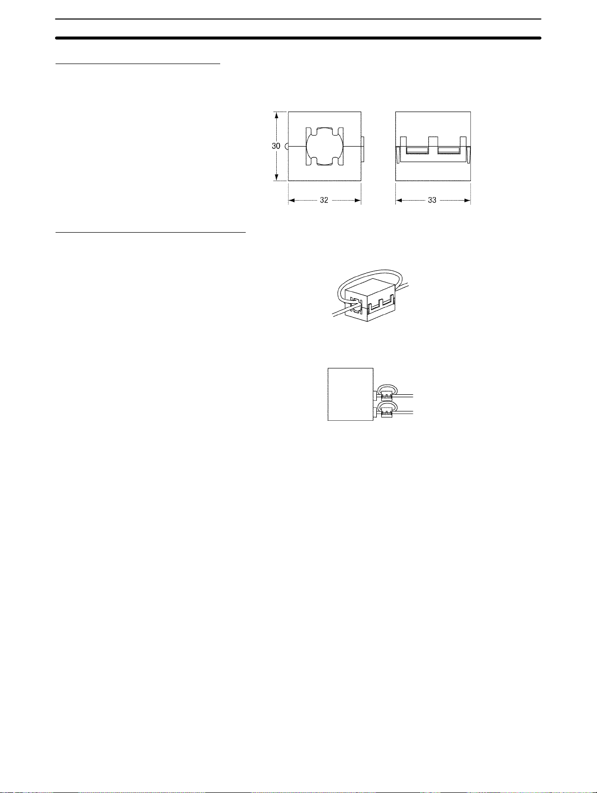
Recommended Ferrite Cores
The following ferrite core (data line noise filter) is recommended:
0443-164151 by Fair-Rite Products Corp.
Low impedance, 25 MHz: 90 Ω, 100 MHz: 160 Ω
Recommended Mounting Method
Mount the core on one turn of the communications cable, as shown in the following illustration.
6Conformance to EC Directives
Mount the cores as closely to the end of the communications cable as possible,
as shown in the following illustration.
Serial
Communications
Board
xvi
Page 13

SECTION 1
Introduction
This section introduces the hardware and software functions of the Serial Communications Board, including the serial communications modes, system configurations, and specifications.
1-1 Overview 2. . . . . . . . . . . . . . . . . . . . . . . . . . . . . . . . . . . . . . . . . . . . . . . . . . . . . . . . . . . . . . .
1-1-1 Model Number 2. . . . . . . . . . . . . . . . . . . . . . . . . . . . . . . . . . . . . . . . . . . . . . . . . . . .
1-1-2 Serial Communications Boards 2. . . . . . . . . . . . . . . . . . . . . . . . . . . . . . . . . . . . . . .
1-1-3 Features 2. . . . . . . . . . . . . . . . . . . . . . . . . . . . . . . . . . . . . . . . . . . . . . . . . . . . . . . . .
1-1-4 System Configuration 3. . . . . . . . . . . . . . . . . . . . . . . . . . . . . . . . . . . . . . . . . . . . . .
1-1-5 Mounting Location 4. . . . . . . . . . . . . . . . . . . . . . . . . . . . . . . . . . . . . . . . . . . . . . . .
1-2 Protocol Overview 4. . . . . . . . . . . . . . . . . . . . . . . . . . . . . . . . . . . . . . . . . . . . . . . . . . . . . . . .
1-2-1 Host Link Mode 5. . . . . . . . . . . . . . . . . . . . . . . . . . . . . . . . . . . . . . . . . . . . . . . . . . .
1-2-2 Protocol Macros 5. . . . . . . . . . . . . . . . . . . . . . . . . . . . . . . . . . . . . . . . . . . . . . . . . . .
1-2-3 No-protocol Communications 6. . . . . . . . . . . . . . . . . . . . . . . . . . . . . . . . . . . . . . . .
1-2-4 PC 1:1 Data Links 6. . . . . . . . . . . . . . . . . . . . . . . . . . . . . . . . . . . . . . . . . . . . . . . . .
1-2-5 NT Links –– 1:N Mode 7. . . . . . . . . . . . . . . . . . . . . . . . . . . . . . . . . . . . . . . . . . . . .
1-2-6 NT Links –– 1:1 Mode 7. . . . . . . . . . . . . . . . . . . . . . . . . . . . . . . . . . . . . . . . . . . . . .
1-3 Specifications 8. . . . . . . . . . . . . . . . . . . . . . . . . . . . . . . . . . . . . . . . . . . . . . . . . . . . . . . . . . . .
1-3-1 Serial Communications Board 8. . . . . . . . . . . . . . . . . . . . . . . . . . . . . . . . . . . . . . . .
1-3-2 General Specifications 8. . . . . . . . . . . . . . . . . . . . . . . . . . . . . . . . . . . . . . . . . . . . . .
1-4 Basic Operating Procedure 8. . . . . . . . . . . . . . . . . . . . . . . . . . . . . . . . . . . . . . . . . . . . . . . . . .
1
Page 14
1-1 Overview
1-1-1 Model Number
Name Model Specifications
Serial Communications Board CQM1H-SCB41 One RS-232 port
1-1-2 Serial Communications Boards
The Serial Communications Board is an Inner Board for the CQM1H-series PCs.
One Board can be installed in Inner Board slot 1 of a CQM1H-series CPU Unit.
The Board cannot be installed in slot 2.
The Board provides two serial communications ports for connecting host computers, Programmable Terminals (PTs), general-purpose external devices, and
Programming Devices (excluding Programming Consoles). This makes it possible to easily increase the number of serial communications ports for a CQM1Hseries PC.
1-1SectionBasic Operating Procedure
One RS-422A/485 port
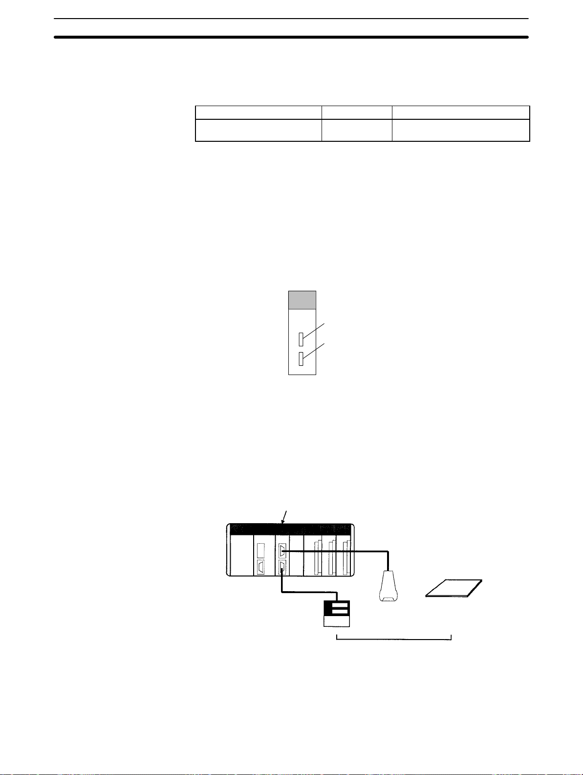
1-1-3 Features
Port 1: RS-232C
Port 2: RS-422A/485
The Serial Communications Board is an option that can be mounted in the CPU
Unit to increase the number of serial ports without using an I/O slot. It supports
protocol macros (which are not supported by the ports built into the CPU Units),
allowing easy connection to general-purpose devices that have a serial port.
Inside controlled machine
Serial Communications Board
RS-232C
RS-422A/485
Temperature controller
or other device
Bar code reader
or other device
OR
Dedicated controller
or other device
External device with RS-232C or
RS-422A/485 port
Both RS-232C and RS-422A/485 ports are provided. The RS-422A/485 port enables 1:N connections to general-purpose external devices without going
through Converting Link Adapters. The 1:N connections can be used with protocol macros or 1:N-mode NT Links.
2
Page 15
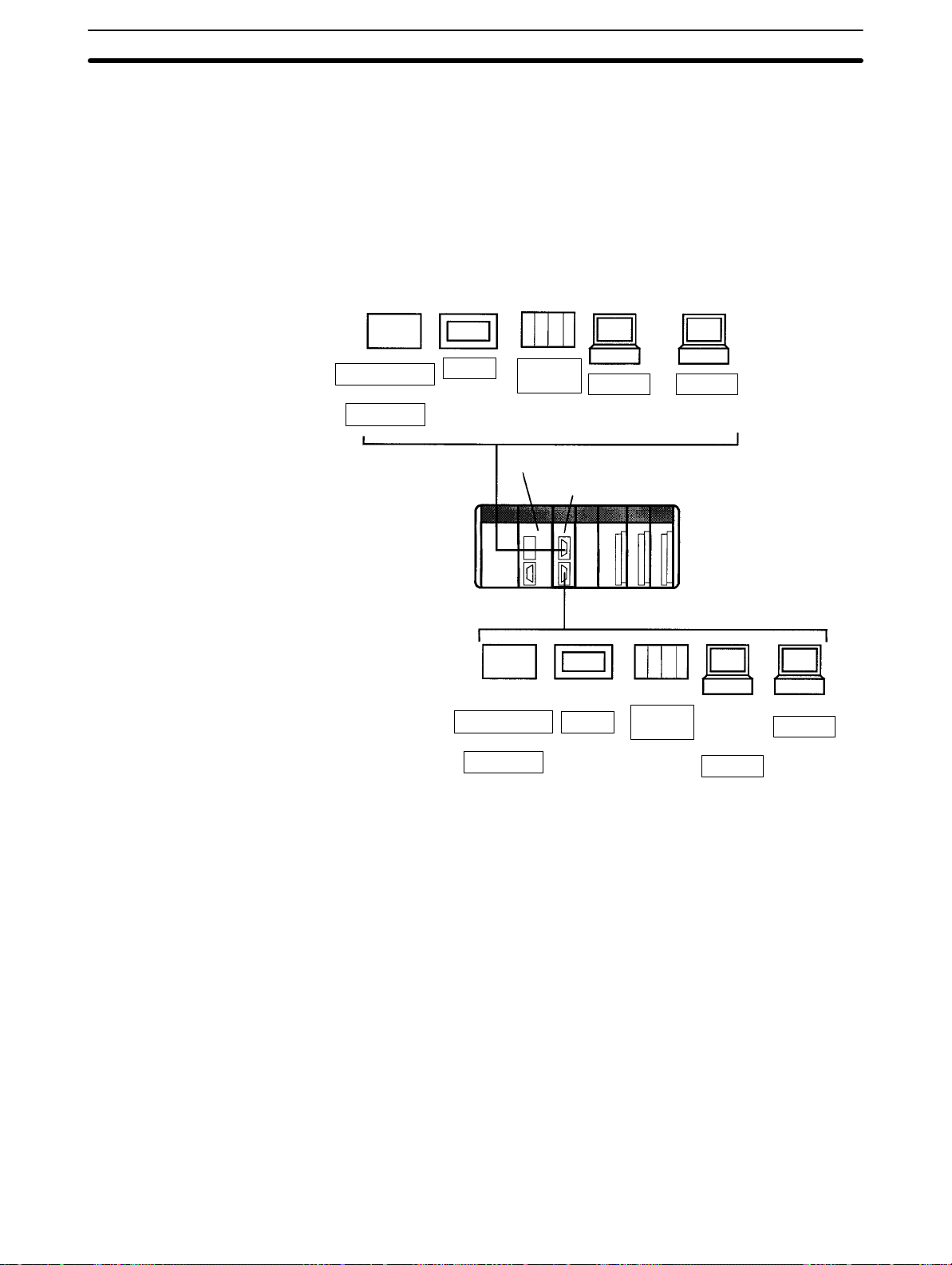
1-1-4 System Configuration
The following serial communications modes are supported by the Serial Communications Board: Host Link (SYSMAC W AY), protocol macro, no-protocol, 1:1
Data Links, 1:N-mode NT Link, and 1:1-mode NT Link modes. The devices
shown in the following diagram can be connected.
Note The 1:1-mode NT Link and 1:N-mode NT Link communications modes use dif-
ferent protocols that are not compatible with each other.
General-purpose
external device
Programmable
Terminal (PT)
C-series PC
Programming
Device
(excluding
Programming
Console)
1-1SectionProtocol Overview
Host computer
Protocol macros
NT Link
1:1
Data Link
Host Link Host Link
No-protocol
RS-232C
CQM1H-series CPU Unit
Serial Communications Board
RS-422A/485
General-purpose
external device
Protocol macros
No-protocol
Programmable
Terminal (PT)
NT Link
C-series PC
1:1
Data Link
Programming
Device
(excluding
Programming
Console)
Host Link
Host computer
Host Link
Note An NT-AL001-E Converting Link Adapter can be used to convert between
RS-232C and RS-422A/485. This Link Adapter requires a 5-V power supply.
Power is provided by the RS-232C port on the Serial Communications Board
when the Link Adapter is connected to it, but must be provided separately when
connecting the Link Adapter to other devices.
3
Page 16
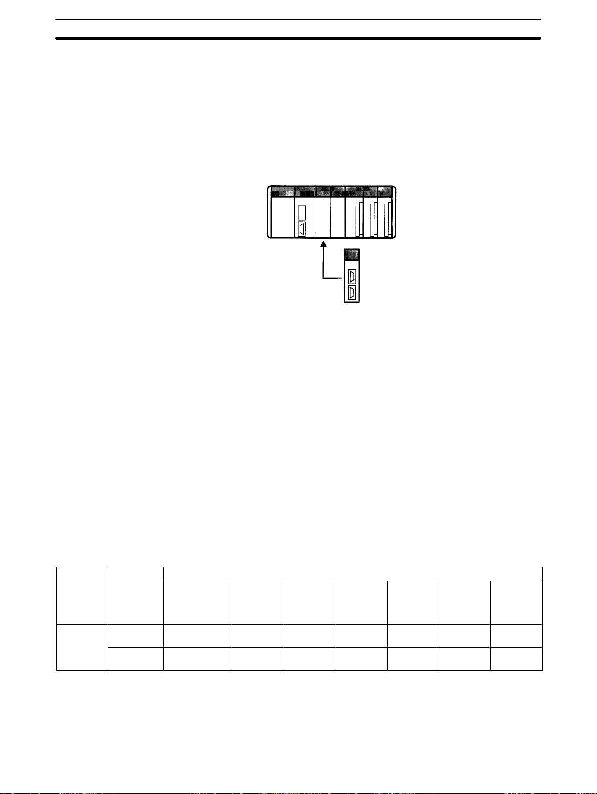
1-1-5 Mounting Location
The Serial Communications Board can be installed in Inner Board slot 1 of a
CQM1H-series CPU Unit. The Board cannot be installed in slot 2.
Slot 2: Not mountable
Slot 1: Mount here
Serial Communications Board
1-2SectionBasic Operating Procedure
1-2 Protocol Overview
The following six serial communications modes can be used as required for
each serial communications port on the Serial Communications Board.
• Host Link:
For connections to host computers, personal computer peripheral devices, or
Programmable Terminals
• Protocol Macros:
For communications with general-purpose external devices using protocols
• No-protocol:
For connections to general-purpose devices for no-protocol communications
using TXD(––) and RXD(––) instructions
• 1:1 Data Links:
For 1:1 data links with a C-series PC, including another CQM1H
• 1:N-mode NT Link:
For communications with one or more Programmable Terminals (PTs)
• 1:1-mode NT Link:
For communications with one PT
Communications Ports and Serial Communications Modes
Board Port
Serial
Communications
Boards
RS-232C
(port 1)
RS-422A/
485 (port 2)
Peripheral
bus or
Programming
Console bus
No OK OK OK OK OK (See
No OK (See
Host Link
(SYSMAC
WAY)
note 1)
Note 1. A 4-wire connection must be used when using Host Link, no-protocol, or 1:1
Data Link communications with an RS-422A/485 connector.
2. The PT Programming Control functions are not supported.
Connection examples for the serial communications modes are shown in the following sections.
Serial communications mode
Protocol
macro
OK OK (See
No-
protocol
note 1)
1:1 Data
Link
OK (See
note 1)
1:N-mode
NT Link
note 2)
OK (See
note 2)
1:1-mode
NT Link
OK (See
note 2)
OK (See
note 2)
4
Page 17
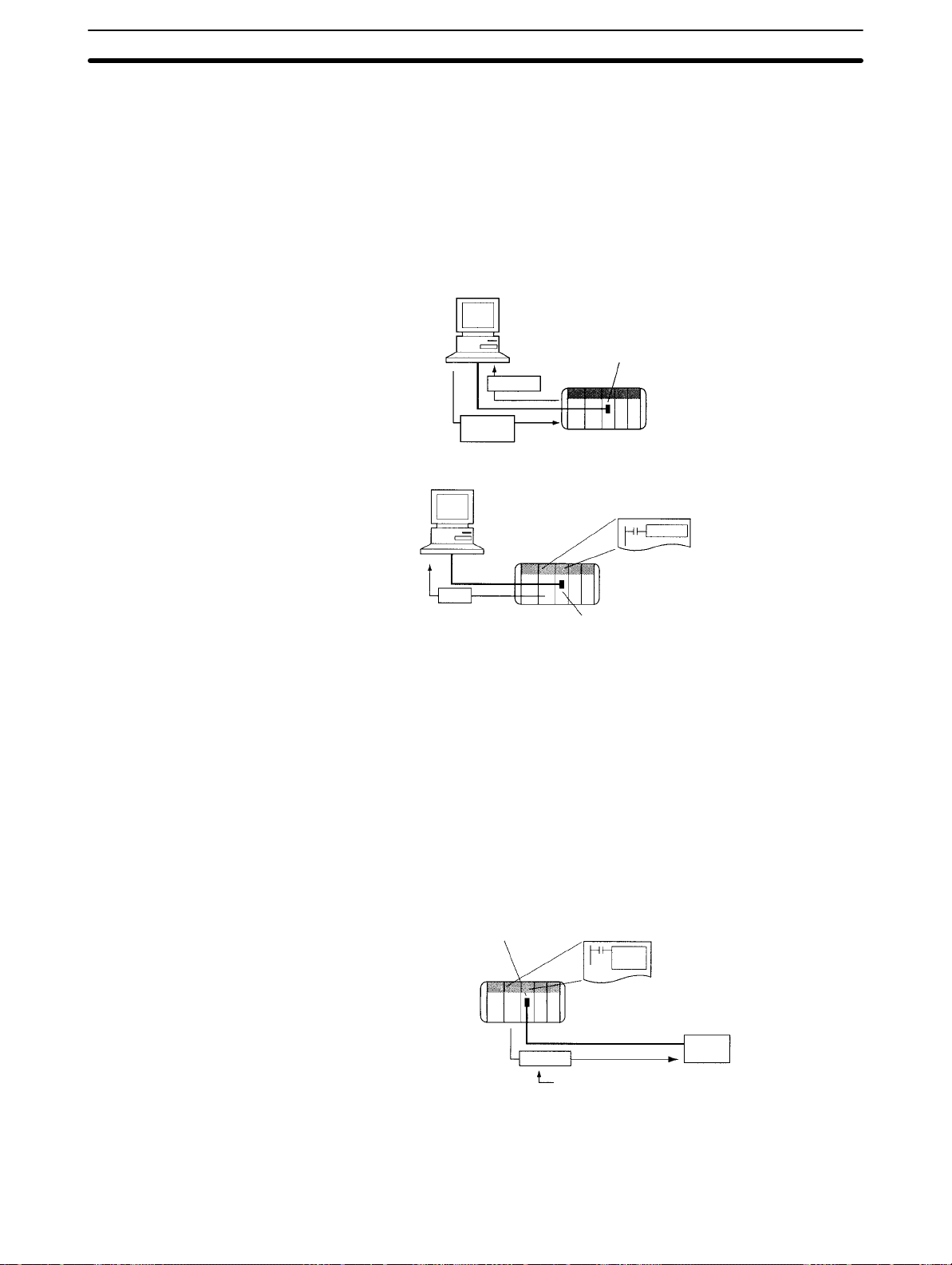
1-2-1 Host Link Mode
In Host Link Mode, C-mode Host Link commands can be sent from a computer,
PT, or other host to read or write I/O memory in the PC or to control the PC’s oper-
ating modes.
The TXD(––) instruction can be used to send ASCII data to the host. This is
called slave-initiated communications or unsolicited communications.
Note 1. Programming Devices can also be connected in Host Link mode.
2. A 4-wire connection must be used when using an RS-422A/485 port.
Sending C-mode Host Link Commands
Slave-initiated Communications
Host computer
Response
Host Link
command
Host computer
1-2SectionProtocol Overview
Serial Communications Board
TXD(––)
1-2-2 Protocol Macros
Data transfer procedures (called protocols) with general-purpose external devices can be created as macros using the CX-Protocol to match the communications specifications of the external device (but, half-duplex communications and
start-stop synchronization must be used).
These protocols are stored in the Serial Communications Boards from the CXProtocol, and enable data to be exchanged with general-purpose external devices simply by executing the PMCR(––) instruction in the CPU Unit.
Standard system protocols for exchanging data with OMRON devices (such as
Temperature Controllers, Intelligent Signal Processors, Bar Code Readers, and
Modems) are provided as a standard feature in the Serial Communications
Boards and the CX-Protocol. The CX-Protocol can also be used to change the
standard system protocols according to user requirements.
Data
CQM1H
Serial Communications Board
CQM1H
Message
PC initiates communication.
Serial Communications Board
PMCR
(––)
External device
RS-232C
Protocol made specifically for the
required communications specifications
with RS-232C port
Note There are some restrictions in using the CX-Protocol to manipulate protocols or
perform other operations for the CQM1H-series Serial Communications Board.
These restrictions are described below.
5
Page 18
• Pin 8 on the DIP switch on the front of the CQM1H-series CPU Unit must be
turned ON t o use the CX-Protocol. While pin 8 is ON, you will not be able to use
any of the CPU Unit or Board ports for the CX-Programmer, SYSMAC-CPT , o r
SYSMAC Support Software.
• The model of PC must be set to the C200HG and the model of CPU Unit must
be set to the CPU43.
• Refer to 5-2 Restrictions in Using the CX-Protocol for further details.
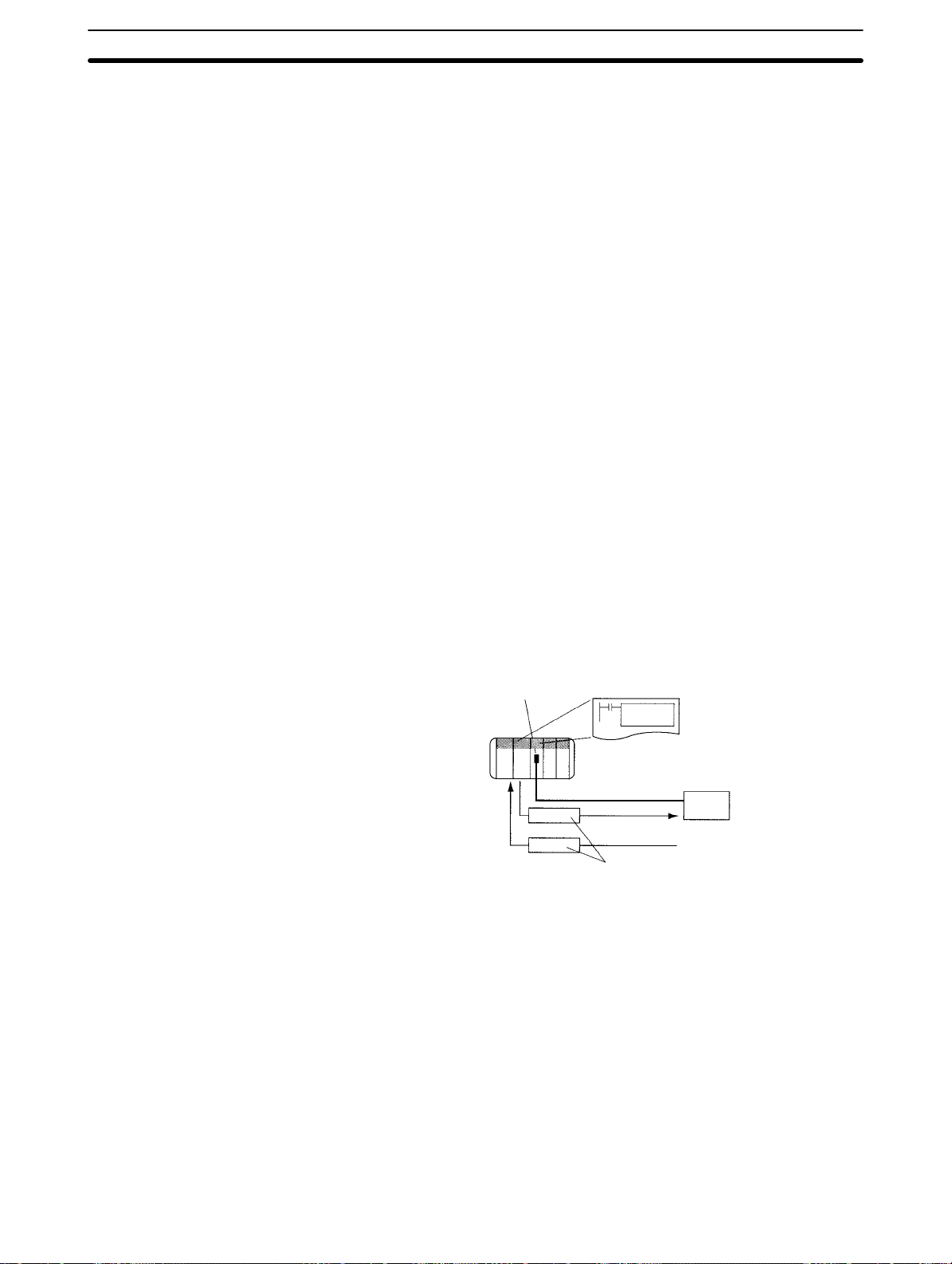
1-2-3 No-protocol Communications
The TXD(––) and RXD(––) instructions can be used in the ladder program to
send and receive data without conversion through the RS-232C port to and from
an external device.
A start code can be sent before the data and an end code can be sent after it.
Alternately, the amount of data being sent can be specified. A communications
frame, however , cannot be created according to the specifications of the partner
device, providing less flexibility than protocol macros. Retry processing, data
form conversions, controlling processing based on a response, and other communications procedures cannot be performed.
1-2SectionBasic Operating Procedure
No-protocol communications are suitable for communications with bar code
readers and other devices that only send data or printers and other devices that
only receive data.
Note A 4-wire connection must be used when using an RS-422A/485 port.
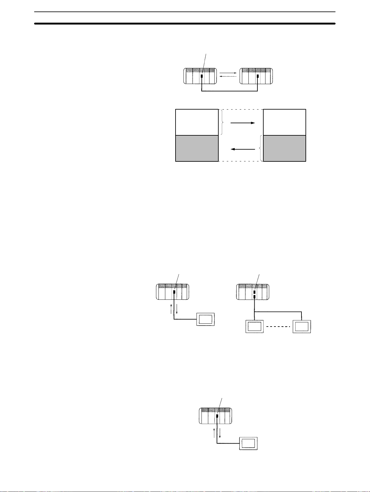
1-2-4 PC 1:1 Data Links
Serial Communications Board
CQM1H
RS-232C
OR
TXD(––) or
RXD(––)
Data only
External device
with RS-232C port
Two PCs can be connected via RS-232C cable to create a data link between
them of u p t o 6 4 words in the LR area. The link words written by one PC are automatically transferred to the other PC for reading.
One of the following three ranges of words can be set to be linked:
LR 00 to LR 63, LR 00 to LR 31, or LR 00 to LR 15
A 1:1 Data Link communications system can be created between the CQM1H
and another CQM1H, or between the CQM1H and the CQM1, C200HX/HG/HE,
C200HS, CPM1, CPM1A, CPM2A, CPM2C, or SRM1(-V2).
6
Page 19
Note A 4-wire connection must be used when using an RS-422A/485 port.
Serial Communications Board
1-2SectionProtocol Overview
1-2-5 NT Links –– 1:N Mode
A PC can be connected to one or more Programmable Terminals (PTs) using an
RS-232C or RS-422A/485 port. The I/O memory of the PC is allocated to the
Status Control Areas and the Status Notification Areas used by the PTs, as well
as to display objects, such as touch switches, lamps, and memory tables. This
enables the status of the I/O memory in the PC to be controlled and monitored by
operations from the PTs, without the use of a ladder diagram programming in the
PC. Up to eight PTs can be connected to a PC.
LR 00
to
LR 31
LR 32
to
LR 63
CQM1H
Master PC Slave PC
Master area
(sent)
Slave area
(received)
CQM1H or other C-series PC
RS-232C
LR 00
to
LR 31
LR 32
to
LR 63
Master area
(received)
Slave area
(sent)
Note The user does not need to be aware of NT Link commands. The user only has to
allocate the PC memory to the PTs.
1-2-6 NT Links –– 1:1 Mode
The functionality of the 1:1 mode is the same as that of the 1:N mode, but only a
1:1 connection is possible. The 1:1 and 1:N modes are not compatible as protocols.
Serial Communications Board
CQM1H
1:1
PT
Serial Communications Board
CQM1H
Serial Communications Board
CQM1H
1:N
RS-422A/485
PT
1:1
PT
PT
7
Page 20

1-3 Specifications
1-3-1 Serial Communications Board
Device name Serial Communications Board
Model number CQM1H-SCB41
Classification CQM1H-series Inner Board
Supporting CPU Units CQM1H-CPU51/61
Number of mountable Boards/PC and
mounting location
Serial communications
ports
Protocols
Software interface with CPU Unit IR 200 to IR 207 (words for Inner Board slot 1)
PC Setup settings DM 6550 to DM 6559 (in read-only DM area in CPU Unit)
Current consumption (see note) 200 mA max. at 5 V DC
Dimensions 25 × 110 × 107 (mm) (W × H × D)
Weight 90 g max.
Standard accessories Socket: XM2SA-0901 (OMRON) (two included)
Port 1 RS-232C
Port 2 RS-422A/485
Port 1
Port 2
One Board per PC maximum, must be in Inner Board slot 1
Host Link, protocol macro, no-protocol, 1:1 Data Link, 1:N-mode NT Link
or 1:1-mode NT Link can be selected for each port.
Set from Programming Device
Hood: XM2SA-0911-E (OMRON) (two included, ESD compatible)
1-4SectionBasic Operating Procedure
Note The current consumption is for one Serial Communications Board. Power is sup-
plied from the CQM1H
When an NT-AL001-E Link Adapter is connected to the Serial Communications
Board, power is supplied to the Link Adapter from the Board. A current consumption of 150 mA must be added for each Link Adapter that is connected. In the
above specifications, “x” indicates that 150 mA must be added for each port to
which an NT-AL001-E Link Adapter is connected to provide the required 5-V
power supply.
1-3-2 General Specifications
Conform to SYSMAC CQM1H-series CPU Unit specifications.
1-4 Basic Operating Procedure
An overview of the basic operating procedure is provided here. Details are provided in sections 4 to 8 of this manual according to the serial communications
mode.
1, 2, 3... 1. Turn OFF the power supply to the PC.
2. Mount the Board.
3. Connect the Board and the external device(s).
4. Turn ON the power supply to the PC.
5. Set the PC Setup settings from a Programming Device (e.g., Programming
Console or CX-Protocol).
6. Execute communications.
Use the control bits, flags, and words allocated in the IR area in the ladder
program to control communications.
8
Page 21

SECTION 2
Board Components and Installation
This section describes the components of the Serial Communications Board, how to connect it in the CPU Unit, and how to
connect it to external devices.
2-1 Component Names and Functions 10. . . . . . . . . . . . . . . . . . . . . . . . . . . . . . . . . . . . . . . . . . . .
2-1-1 Indicators 10. . . . . . . . . . . . . . . . . . . . . . . . . . . . . . . . . . . . . . . . . . . . . . . . . . . . . . . .
2-1-2 RS-232C Port 11. . . . . . . . . . . . . . . . . . . . . . . . . . . . . . . . . . . . . . . . . . . . . . . . . . . . .
2-1-3 RS-422A/485 Port 12. . . . . . . . . . . . . . . . . . . . . . . . . . . . . . . . . . . . . . . . . . . . . . . . .
2-1-4 Switches 13. . . . . . . . . . . . . . . . . . . . . . . . . . . . . . . . . . . . . . . . . . . . . . . . . . . . . . . . .
2-2 Installation 14. . . . . . . . . . . . . . . . . . . . . . . . . . . . . . . . . . . . . . . . . . . . . . . . . . . . . . . . . . . . . .
2-2-1 Mounting the Board 14. . . . . . . . . . . . . . . . . . . . . . . . . . . . . . . . . . . . . . . . . . . . . . . .
2-2-2 External Dimensions 15. . . . . . . . . . . . . . . . . . . . . . . . . . . . . . . . . . . . . . . . . . . . . . .
2-2-3 Mounting Height and Connector Cover Dimensions 15. . . . . . . . . . . . . . . . . . . . . .
2-2-4 Precautions in Handling the Board 16. . . . . . . . . . . . . . . . . . . . . . . . . . . . . . . . . . . .
2-3 Wiring 17. . . . . . . . . . . . . . . . . . . . . . . . . . . . . . . . . . . . . . . . . . . . . . . . . . . . . . . . . . . . . . . . . .
2-3-1 Connectors 17. . . . . . . . . . . . . . . . . . . . . . . . . . . . . . . . . . . . . . . . . . . . . . . . . . . . . . .
2-3-2 Wiring Precautions 18. . . . . . . . . . . . . . . . . . . . . . . . . . . . . . . . . . . . . . . . . . . . . . . . .
2-3-3 Reducing Electrical Noise for External Wiring 18. . . . . . . . . . . . . . . . . . . . . . . . . . .
2-3-4 Port Applicability and Restrictions for 2-Wire/4-Wire Connections 19. . . . . . . . . . .
2-3-5 Recommended RS-232C Wiring Examples 20. . . . . . . . . . . . . . . . . . . . . . . . . . . . . .
2-3-6 Recommended RS-422A/485 Wiring Examples 21. . . . . . . . . . . . . . . . . . . . . . . . . .
2-3-7 Wiring Connectors 23. . . . . . . . . . . . . . . . . . . . . . . . . . . . . . . . . . . . . . . . . . . . . . . . .
2-3-8 Soldering 25. . . . . . . . . . . . . . . . . . . . . . . . . . . . . . . . . . . . . . . . . . . . . . . . . . . . . . . .
2-3-9 Assembling Connector Hood 25. . . . . . . . . . . . . . . . . . . . . . . . . . . . . . . . . . . . . . . . .
2-3-10 Connecting to the Board 26. . . . . . . . . . . . . . . . . . . . . . . . . . . . . . . . . . . . . . . . . . . .
9
Page 22
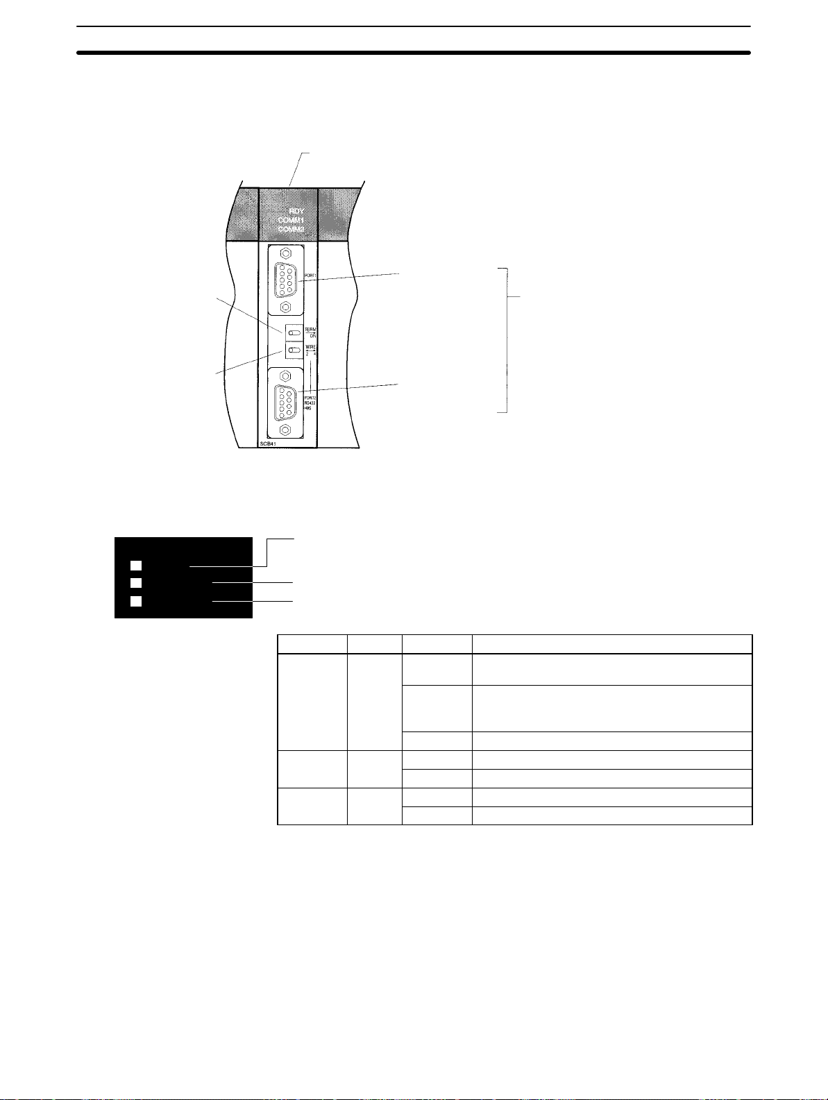
2-1 Component Names and Functions
The components of the Serial Communications Board are described in this section.
Serial Communications Board
(Inner Board slot 1)
Port 1:
RS-232C
Terminating resistance
switch
2-1SectionInstallation
Applicable Connectors
Socket: XM2SA-0901 (OMRON)
Hood: XM2SA-0911-E (OMRON)
(Two of each are included with the Board)
2-wire or 4-wire switch
2-1-1 Indicators
Board Indicators
RDY
COMM1
COMM2
Port 2:
RS-422A/485
There are three LED indicators on the Board, as described below.
RDY: Lit when the Board is operational (green)
COMM1: Lit when data is being sent or received on the RS-232C port (Yellow)
COMM2: Lit when data is being sent or received on the RS-442A/485 port (Yellow)
Indicator Color Status Meaning
RDY Green
COMM1 Yellow
COMM2 Yellow
Lit Operating normally, and protocol macro
preparations have been completed.
Flashing There is an error in the PC Setup settings for the
Board or in the protocol macros contained in the
Board.
Not lit A hardware error has occurred in the Board.
Flashing Port 1 is being used for sending or receiving.
Not lit Port 1 is not being used for sending or receiving.
Flashing Port 2 is being used for sending or receiving.
Not lit Port 2 is not being used for sending or receiving.
10
Page 23
2-1SectionWiring
CPU Unit Indicators
A Serial Communications Board is mounted as an Inner Board in the CPU Unit
and thus affects the CPU Unit ERR/ALM indicator.
Indicator Color Status Meaning
ERR/ALM Red
Lit Fatal error If a fatal error occurs, the CPU
Unit will stop operation in
either RUN or MONITOR
mode.
Flashing Non-fatal
error
Not lit Normal
operation
If a non-fatal error occurs, the
CPU Unit will continue
operation in either RUN or
MONITOR mode.
The CPU Unit is operating
normally. This indicator will
also not be lit when a
watchdog timer error occurs.
If an error in the Inner Board is the cause of the error indicated on the ERR/ALM
indicator, the Inner Board Error Flag (SR 25415) will turn ON and information on
the error will be stored in AR 0400 to AR 0407. Refer to Section 9 Troubleshoot-
ing and Maintenance for details.
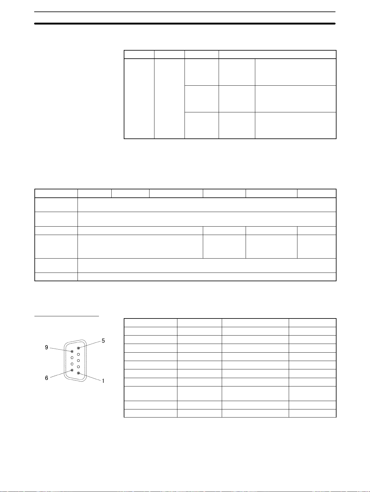
2-1-2 RS-232C Port
Protocol Host Link No-protocol Protocol macros 1:1 Data Links 1:N NT Links 1:1 NT Links
Communications method
Synchronization
Baud rate 1,200/2,400/4,800/9,600/ 19,200 bps 19,200 bps 38,400 bps 19,200 bps
Connections 1:1
Transmission
distance
Interface Complies with EIA RS-232C
Half-duplex
Start-stop synchronization (asynchronous)
(1:N possible using Converting Link Adapters)
15 m max. (See note)
Note The maximum cable length for RS-232C is 15 m. The RS-232C standard, how-
ever, does not cover baud rates above 19.2 Kbps. Refer to the manual for the
device being connected to confirm support.
1:1 1:1
(1:N possible using Link Adapters)
1:1
Connector Pin Layout
Pin No. Abbreviation Signal name I/O
1 (See note 1) FG Shield --2 SD Send data Output
3 RD Receive data Input
4 RTS (RS) Request to send Output
5 CTS (CS) Clear to send Input
6 (See note 2) 5V Power supply --7 DSR (DR) Data set ready Input
8 DTR (ER) Data terminal ready
(See note 4)
9 SG Signal ground --Shell (See note 1) FG Shield ---
Output
Note 1. Pin No. 1 and the shell are connected to the ground terminal (GR) of the
Power Supply Unit inside the Serial Communications Board. Therefore, the
cable shield can be grounded by grounding GR of the Power Supply Unit.
2. Pin 6 (5 V) is required when the NT-AL001-E Link Adapter is connected. For
details on connection methods, refer to 2-3 Wiring.
11
Page 24
Caution Do not connect the 5-V power supply of pin 6 to any external device other than an
!
NT-AL001-E Link Adapter. Otherwise, the external device and the Serial Communications Board may be damaged.
The following cables are provided for connection to NT-AL001-E Link Adapters.
We recommend that these cables be used.
NT-AL001-E connecting cables: XW2Z-070T-1 (0.7 m)
XW2Z-200T-1 (2 m)
2-1SectionInstallation
Applicable Connectors
Socket: XM2A-0901 (OMRON) or equivalent
Hood: XM2S-0911-E (OMRON, conforms to ESD) or equivalent
One Socket and one Hood are provided for each port.
Recommended Cables
UL2464 AWG28 5P IFS-RVV-SB (UL-approved, Fujikura Ltd.)
AWG28 5P IFVV-SB (not UL-approved, Fujikura Ltd.)
UL2464-SB (MA) 5P 28AWG (7/0.127) (UL-approved, Hitachi Cable, Ltd.)
CO-MA-VV -SB 5P 28AWG (7/0.127) (not UL-approved, Hitachi Cable, Ltd.)
Cable length: 15 m max.
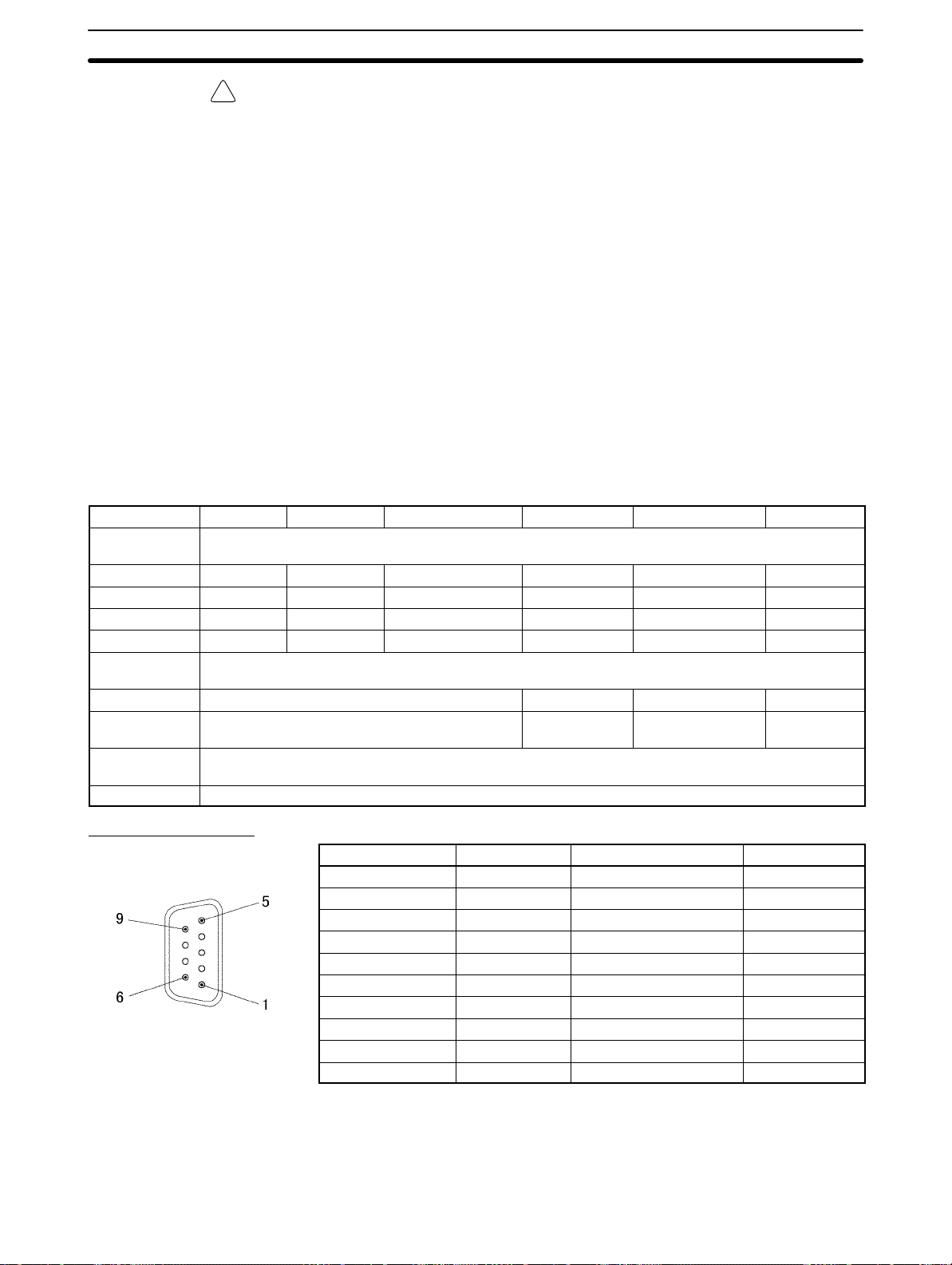
2-1-3 RS-422A/485 Port
Protocol Host Link No-protocol Protocol macros 1:1 Data Links 1:N NT Links 1:1 NT Links
Communications method
4-wire, 1:1 OK OK OK OK OK OK
4-wire, 1:N OK OK OK No OK No
2-wire, 1:1 No No OK No OK No
2-wire, 1:N No No OK No OK No
Synchroniza-
tion
Baud rate 1,200/2,400/4,800/9,600/ 19,200 bps 19,200 bps 38,400 bps 19,200 bps
Connections 1:N (N: 32 Units max.) 1:1 1:N (N: 8 Units
Transmission
distance
Interface Complies with EIA RS-485
Half-duplex
Start-stop synchronous (asynchronous)
1:1
max.)
500 m max.
(The total combined cable length is 500 m max. T-branch lines must be a maximum of 10 m long.)
Connector Pin Layout
12
Pin No. Abbreviation Signal name I/O
1 (See note 1) SDA Send data – Output
2 (See note 1) SDB Send data + Output
3 NC Not used --4 NC Not used --5 NC Not used --6 (See note 1) RDA Receive data – Input
7 NC Not used --8 (See note 1) RDB Receive data + Input
9 NC Not used --Shell (See note 2) FG Shield ---
Note 1. When 2-wire connections are used, use pins 1 and 2, or pins 6 and 8.
2. The shell is connected to the ground terminal (GR) of the Power Supply Unit
inside of the Serial Communications Board. Therefore, the cable shield can
be grounded by grounding the GR of the Power Supply Unit.
Page 25
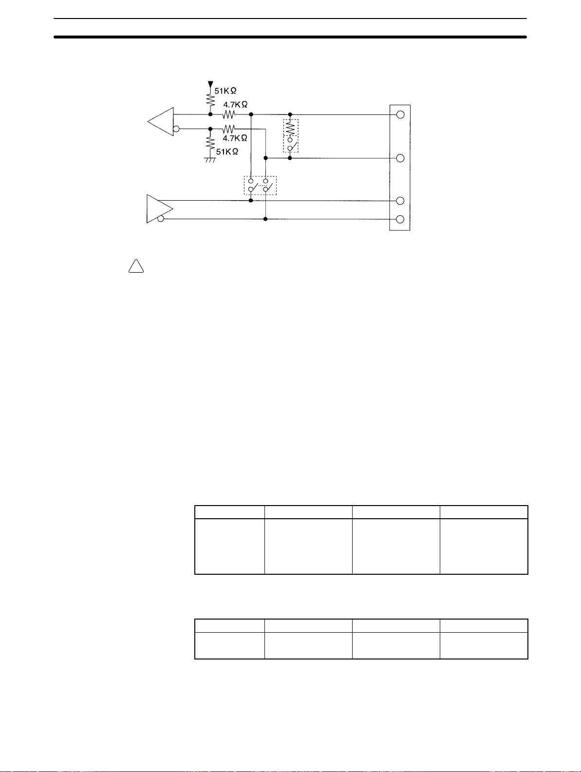
2-1SectionWiring
Internal Circuits
Receiver
Driver
Caution Confirm polarities before connecting RS-422A/485 cables. Some devices re-
!
Applicable Connectors
The internal circuits for port 2 are shown below.
Pin 8: RDB (+)
Terminating resistance: 200 Ω
Terminating resistance switch
Pin 6: RDA (–)
2-wire/4-wire switch
Pin 2: SDB (+)
Pin 1: SDA (–)
quire that SDA/B and RDA/B or signal polarities be reversed.
Socket: XM2A-0901 (OMRON) or equivalent
Hood: XM2S-0911-E (OMRON, conforms to ESD) or equivalent
One Socket and one Hood are provided for each port.
Recommended Cables
2-1-4 Switches
Terminating Resistance
Switch
2-Wire or 4-Wire Switch
CO-HC-ESV-3P 7/0.2 (Hirakawa Hewtech Corp.)
Cable length: 500 m max.
(The total combined cable length is 500 m max. T -branch lines must be a maximum of 10 m long.)
The TERM and WIRE switches are on the front panel of the Serial Communications Board. Refer to page 10 for a diagram of the Board.
When an RS-422/485 port is used, turn ON the switch if the Serial Communications Board is on the end of the transmission line. Refer to information on specific
serial communications modes for the ON/OFF settings.
Label Name Settings Factory setting
TERM Terminating
resistance switch
OFF:Terminating
resistance
OFF
ON: Terminating
resistance ON
OFF:Terminating
resistance
OFF
When an RS-422/485 port is used, set the switch to 2 when 2-wire connections
are used, and set the switch to 4 when 4-wire connections are used.
Label Name Settings Factory setting
WIRE 2-wire or 4-wire
switch
2: 2-wire
4: 4-wire
2: 2-wire
Note Host Link, no-protocol, and 1:1 Data Link modes cannot use 2-wire
RS-422A/485 communications. Always use 4-wire connections when using
RS-422A/485 communications for these serial communications modes. Refer
to 2-3 Wiring for connections.
13
Page 26
2-2 Installation
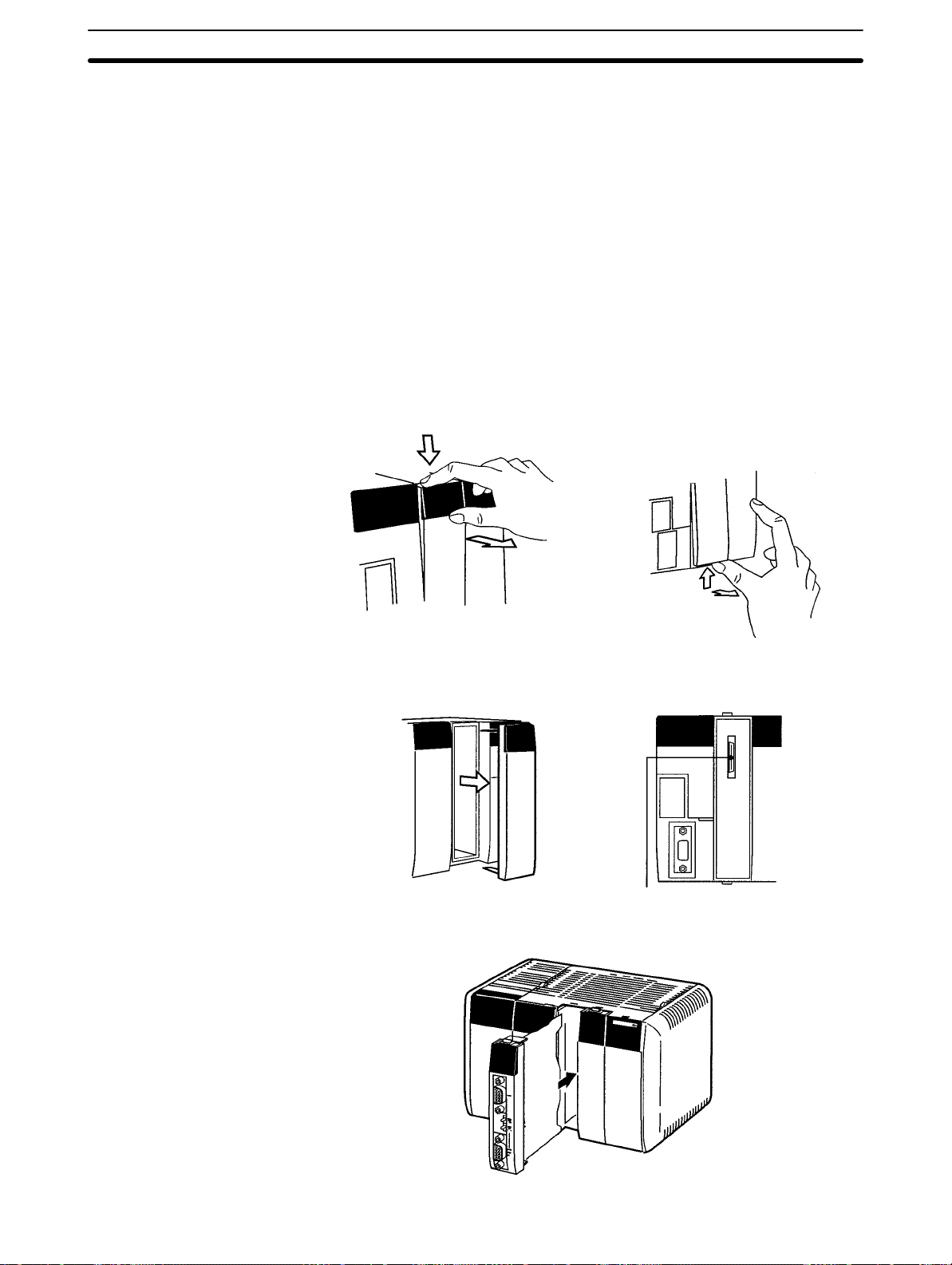
2-2-1 Mounting the Board
This section describes how to mount a Serial Communications Board in Inner
Board slot 1 of a CPU Unit. Slot 1 is the slot on the left. Only one Serial Communications Board can be installed in each CPU Unit.
Note 1. The Serial Communications Board cannot be mounted in Inner Board slot 2.
2. Always turn OFF the power before installing or removing the Serial Communications Board. Installing or removing the Serial Communications Board
with the power ON can cause the CPU Unit to malfunction, damage internal
components, or cause communications errors.
3. Before handling the Serial Communications Board, touch a grounded metallic object in order to discharge any static build-up from your body.
1, 2, 3... 1. Press the catches at the top and bottom of the Inner Board slot 1 compart-
ment cover.
2-2SectionInstallation
Press the top catch. Press the bottom catch.
2. Remove the compartment cover.
Inner Board Connector
3. Insert the Serial Communications Board.
14
Page 27
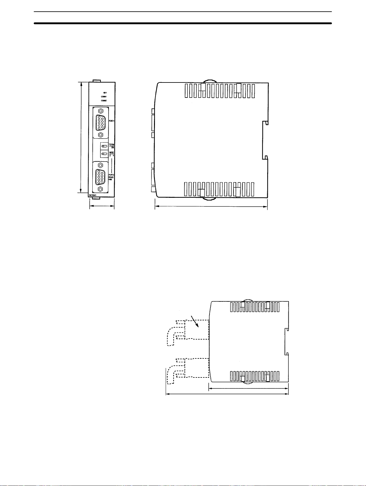
2-2-2 External Dimensions
CS1W-SCB41
110
2-2SectionWiring
Unit: mm
Mounted in the CPU Unit
10725
2-2-3 Mounting Height and Connector Cover Dimensions
When mounting the Serial Communications Board, make sure to provide space
for the mounting height and connector cover dimensions shown below.
Serial Communication Unit
mounted in the CPU Unit
Connecting Cable connector
123
223
Note The mounting heights shown above are applicable when the attached connec-
tors, connector covers, and recommended cables are used. The mounting
height may differ when other connectors, connector covers, and cables are
used. Determine the mounting height, taking into account the connectors, connector covers, and the minimum bending radius of the cables.
15
Page 28
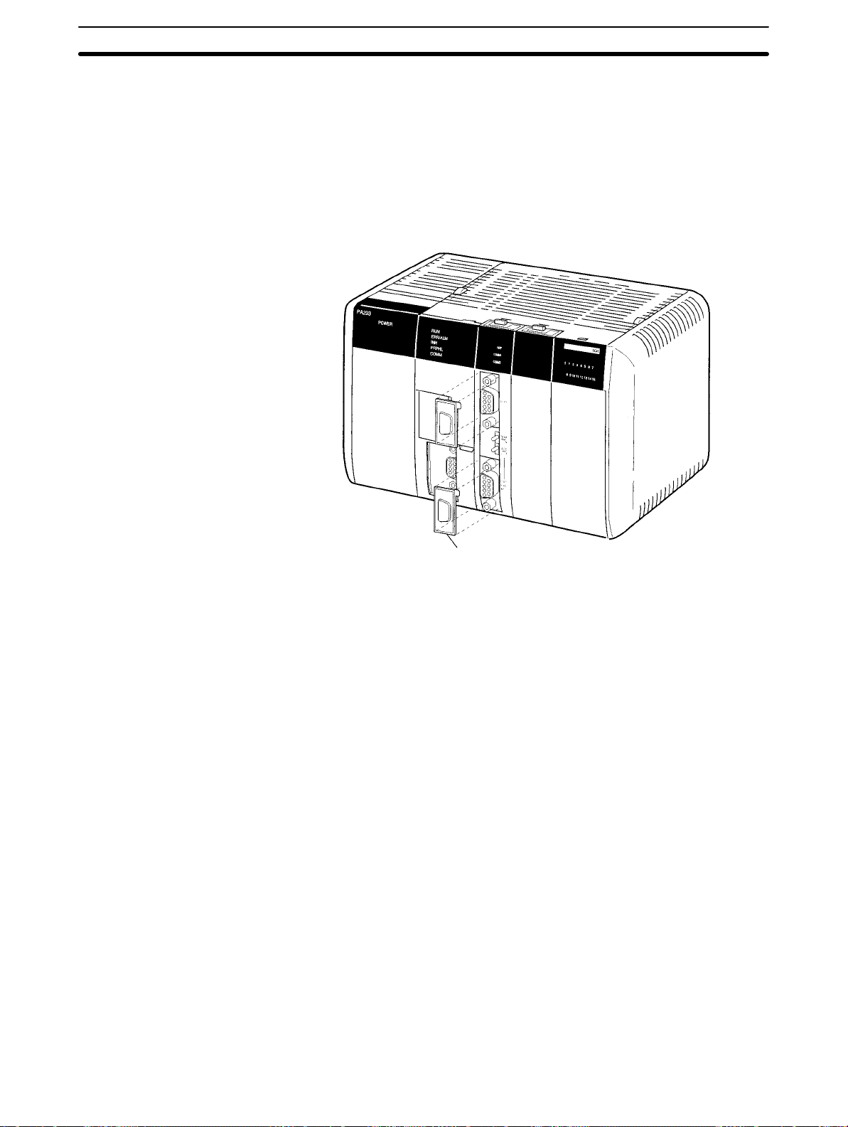
2-2-4 Precautions in Handling the Board
• Turn OFF the power supply to the CPU Unit before mounting or removing the
Board.
• Turn OFF the power supply to the CPU Unit before before connecting or disconnecting Board connectors or wiring.
• Separate the port connector lines from the high-tension or power lines to reduce external noise.
• Leave the port cover attached when not using a communications port.
2-2SectionInstallation
Port cover
16
Page 29
2-3 Wiring
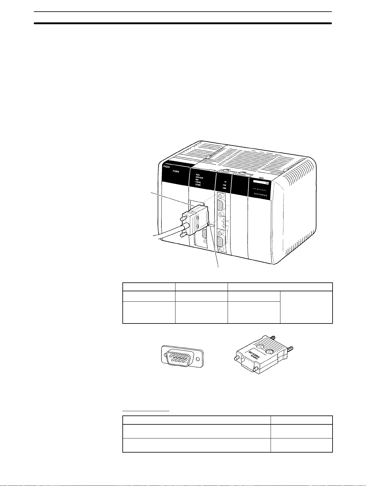
2-3-1 Connectors
2-3SectionWiring
Prepare connecting cables for port 1 (RS-232C) and port 2 (RS422A/485) using
the Sockets and Hoods provided with the Board and the recommended cables.
Connection methods vary with the serial communications mode that is being
used. Refer to the following sections for connection examples.
Host Link: Section 4 Host Link Communications
Protocol macros: Section 5 Protocol Macros
No-protocol: Section 6 Non-protocol Communications
1:1 Data Links: Section 7 Communications for 1:1 Data Links
NT Links: Section 8 NT Link Communications
Hood
Standard Connectors
(for Both RS-232C and
RS-422A/485)
Recommended Cables
Socket
Name Model Specifications
Socket XM2A-0901 9-pin male
Hood XM2S-0911-E For 9-pin, metric
screws, conforms
to ESD
Socket:
XM2A-0901
Hood:
XM2S-0911-E
RS-232C Cables
Model Manufacturer
UL2464 AWG28×5P IFS-RVV-SB (UL-approved)
AWG28×5P IFVV-SB (not UL-approved)
UL2464-SB (MA) 5P×AWG28 (7/0.127) (UL-approved)
CO-MA-VV-SB 5P×AWG28 (7/0.127) (not UL-approved)
Used together
(provided with
Serial
Communications
Board).
Fujikura Ltd.
Hitachi Cable, Ltd.
17
Page 30
RS-422A/485 Cable
CO-HC-ESV-3P×7/0.2 Hirakawa Hewtech Corp.
Refer to pages 11 and 12 for the connector pin layouts. Refer to 2-3-5 Recom-
mended RS-232C Wiring Examples and 2-3-6 Recommended RS-422A/485
Wiring Examples for wiring examples, and to 2-3-7 Wiring Connectors for wiring
methods.
Standard cables are available for connection to personal computers and PTs.
Refer to Section 4 Host Link Communications for personal computer cables and
to your PT user’s manual for PT cables.
2-3-2 Wiring Precautions
• Before connecting or disconnecting the communications cables, always make
sure that the PC is turned OFF.
• Tighten the communications connector screws firmly with your fingers.
• Serial Communications Boards can be connected to various devices. For
compatibility, refer to the operation manuals for the devices to which they are to
be connected.
2-3SectionInstallation
Model Manufacturer
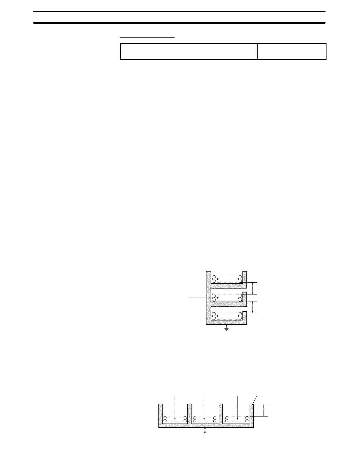
2-3-3 Reducing Electrical Noise for External Wiring
Observe the following precautions for external wiring.
• When multi-conductor signal cable is being used, avoid using I/O wires and
other control wires in the same cable.
• If wiring racks are running in parallel, allow at least 300 mm between the racks.
Low-current cables
Communications
cables
Control cables
PC power supply
and general control
circuit wiring
Power lines
• If the I/O wiring and power cables must be placed in the same duct, they must
be shielded from each other using grounded steel sheet metal.
PC power supply
Communications
cables
and general control
circuit wiring
Power cables
Ground to 100 Ω or less.
Power lines
300 mm min.
300 mm min.
Steel sheet metal
18
200 mm min.
Ground to 100 Ω or less.
Page 31

2-3SectionWiring
2-3-4 Port Applicability and Restrictions for 2-Wire/4-Wire Connections
The following table shows the port connections that can be used for each serial
communications mode.
Serial communications
mode
Host Link OK OK (See
Protocol macros OK OK OK OK OK
No-protocol OK OK OK No No
1:1 Data Links OK No OK No No No
1:N-mode NT Links OK OK OK OK OK
1:1-mode NT Links OK No OK No No No
RS-232C port RS-422A/485 port
1:1 1:N
OK OK No No
note 2)
4-wire 2-wire
1:1 1:N 1:1 1:N
Note 1. The 1:N connection method can be used by converting between RS-232C
and RS-422A/485 through NT-AL001-E Converting Link Adapters.
2. Use 4-wire connections between the Converting Link Adapters.
3. The 2-wire RS-422A/485 connections cannot be used for Host Link communications. Use 4-wire connections.
The transmission circuits for 2-wire and 4-wire connections are different, as
shown in the following diagram.
Example of 4-Wire Connections
Example of 2-Wire Connections
2/4-wire switch
(DPDT)
Board
NT-AL001-E Link Adapter
Settings
2/4-wire switch
Other Unit
Other Unit
(DPDT)
Board
Not connected
Other UnitOther Unit
Note 1. Use the same transmission circuit (2-wire or 4-wire) for all nodes.
2. Do not use 4-wire connections when the 2/4-wire switch on the Board is set
to 2-wire.
The NT-AL001-E Link Adapter has a DIP switch for setting RS-422A/485 communications conditions. When connecting the Board, refer to the DIP switch settings shown in the following table.
19
Page 32

Pin Function Factory
1 Not used. Always set this pin to ON. ON
2 Built-in terminating resistance setting
ON: Connects terminating resistance.
OFF: Disconnects terminating resistance.
3
4
5
2/4-wire setting
2-wire: Set both pins to ON.
4-wire: Set both pins to OFF.
Transmission mode (See note)
Constant transmission: Set both pins to OFF.
Transmission performed when CTS signal in RS-232C
6
Transmission performed when CTS signal in RS-232C
interface is at high level: Set pin 5 to OFF and pin 6 to ON.
Transmission performed when CTS signal in RS-232C
interface is at low level: Set pin 5 to ON and pin 6 to OFF.
Note When connecting to a CQM1H-series CPU Unit, turn OFF pin 5 and turn ON pin 6.
2-3-5 Recommended RS-232C Wiring Examples
It is recommended that RS-232C cables be connected as described below, especially when the Serial Communications Board is used in an environment
where it is likely to be subject to electrical noise.
2-3SectionInstallation
setting
ON
OFF
OFF
ON
OFF
Serial
Communications
Board
Pin Signal
SD
RD
RTS
CTS
SG
FG
Hood
FG
1, 2, 3... 1. Always use shielded twisted-pair cables as communications cables.
Model Manufacturer
UL2464 AWG28x5P IFS-RVV-SB (UL-approved)
Fujikura Ltd.
AWG28x5P IFVV-SB (not UL-approved)
UL2464-SB (MA) 5Px28AWG (7/0.127) (UL-approved)
CO-MA-VV-SB 5Px28AWG (7/0.127) (not UL-approved)
Hitachi Cable,
Ltd.
2. Combine signal wires and SG (signal ground) wires in a twisted-pair cable.
At the same time, bundle the SG wires to the connectors on the Serial Communications Board and the remote device.
3. Connect the shield of the communications cable to the Hood (FG) terminal
of the RS-232C connector on the Serial Communications Board. At the
same time, ground the ground (GR) terminal of the Power Supply Unit to
100 Ω or less.
4. A connection example is shown below.
Example: Twisted-pair Cable Connecting SD-SG, RD-SG, RTS-SG, and
CTS-SG Terminals
Actual Wiring Example
SG signal wires
Remote device
Signal
RD
SD
CTS
RTS
SG
FG
Shield
Twist the braided shield to make
it thinner and connect to Pin No.
1 (FG). Cover this section with
heat-shrink tube to avoid contact
with other sections.
Bundle the SG wires.
Aluminum foil
20
XM2S-0911-E
Page 33

2-3SectionWiring
Note The Hood (FG) is internally connected to the ground terminal (GR) on the Power
Supply Unit. Therefore, FG is grounded by grounding the ground terminal (GR)
on the Power Supply Unit. Although there is conductivity between the Hood (FG)
and pin 1 (FG), connect the Hood (FG) to the shield because the Hood (FG) has
smaller contact resistance with the shield than pin 1 (FG), and thus provides better noise resistance.
Power Supply Unit
Hood and GR are
internally connected.
Ground to 100 Ω or less Grounding the GR terminal
grounds the Hood (FG).
Serial Communications Board
2-3-6 Recommended RS-422A/485 Wiring Examples
Recommended RS-422A/485 Cable
We recommend the following wiring methods to ensure quality transmissions for
RS-422A/485 communications.
1, 2, 3... 1. Always use shielded twisted-pair cables for the communications cables.
2-Wire Connections
Model Manufacturer
CO-HC-ESV-3Px7/0.2 Hirakawa Hewtech Corp.
2. Connect the shield of the communications cable to the Hood (FG) of the
RS-422A/485 connector on the Serial Communications Board. At the same
time, ground the ground (GR) terminal of the Power Supply Unit to 100 Ω or
less.
Note Always ground the shield only at the Board end. Grounding both ends of the
shield may damage the device due to the potential difference between the
ground terminals.
Connection examples are shown below.
Serial Communications
Board
Pin
Signal
Hood
Shield
Remote device
Signal
21
Page 34

4-Wire Connections
Using a 3G2A9-AL001 Link Adapter
Serial Communications
Board
Signal
Pin
Hood
Serial Communications
Board
Pin
Signal
Hood
Pin
Signal
Pin
3G2A9-AL001
Signal
RS-422
interface
Shield
Signal Pin
2-3SectionInstallation
Remote device
Signal
Remote device
Signal
Remote device
Signal
Using an NT-AL001-E RS-232C/RS-422 Link Adapter
Serial Communications
Board
Pin
Hood
Signal
SD
RD
RTS
CTS
5V
DSR
DTR
SG
FG
Pin
Signal
RD
SD
CTS
RTS
5V
DSR
DTR
SG
Shield
(See note.)
Note The following cables are available for this connection.
Length Model
70 cm XW2Z-070T-1
2 m XW2Z-200T-1
NT-AL001-E
Signal
Pin
Remote device
Signal
Remote device
Signal
22
It is recommended that one of these cables be used to connect the RS-232C port
on the Serial Communications Board to the NT-AL001-E Converting Link Adapter.
Page 35

2-3SectionWiring
Note The Hood (FG) is internally connected to the ground terminal (GR) on the Power
Supply Unit. Therefore, FG is grounded by grounding the ground terminal (GR)
on the Power Supply Unit.
3. Be sure to turn ON the terminating resistance at the last Unit at the end of the
2-3-7 Wiring Connectors
Use the following steps to wire connectors.
Cable Preparation
See the following diagrams for the length of the cable portion to be cut in each
step.
Power Supply Unit
Serial Communications Board
Hood and GR are
internally connected.
Ground to 100 Ω or less Grounding the GR terminal
grounds the Hood (FG).
RS-422A/485 cable.
Shield Connected to Hood (FG)
1, 2, 3... 1. Cut the cable to the required length.
2. Remove the specified length of the sheath from the cable using a knife. Be
careful not to scratch the braided shield.
25 mm (RS-422A)
40 mm (RS-232C)
3. Trim off the braided shield using scissors so that the remaining shield length
is 10 mm.
10 mm
4. Remove the insulation from each conductor using a stripper so that the exposed conductor length is 5 mm.
5 mm
23
Page 36

5. Fold back the braided shield.
6. Wrap aluminum foil tape around the folded shield.
Shield Not Connected to Hood (FG)
1, 2, 3... 1. Cut the cable to the required length.
2. Remove the specified length of the sheath from the cable using a knife. Be
2-3SectionInstallation
Aluminum foil tape
careful not to scratch the braided shield.
25 mm (RS-422A)
40 mm (RS-232C)
3. Trim off all the braided shield using scissors.
4. Remove the insulation from each conductor using a stripper so that the exposed conductor length is 5 mm.
5 mm
5. Wrap adhesive tape around the conductor from which the braided shield
was removed.
Adhesive tape
24
Page 37

2-3-8 Soldering
1, 2, 3... 1. Thread a heat-shrinking tube through each conductor.
2-3SectionWiring
2. Temporarily solder each conductor to the corresponding connector terminals.
3. Completely solder each conductor.
Soldering iron
Heat-shrinking tube
Inside diameter:
1.5 mm, l = 10
4. Return the heat-shrinking tube to the soldered portion, then heat the tube to
shrink it in place.
2-3-9 Assembling Connector Hood
Assemble the connector Hood as shown below.
Heat-shrinking tube
Grounding plate
End connected to FG
Adhesive tape
End not connected to FG
Aluminum foil tape
25
Page 38

2-3-10Connecting to the Board
Tighten the screws firmly
with your fingers.
2-3SectionInstallation
26
Page 39

SECTION 3
Default Settings and Related Bits/Flags
This section describes the settings, control bits, flags, and status information available in the CPU Unit for use with the Serial
Communications Board.
3-1 Overview 28. . . . . . . . . . . . . . . . . . . . . . . . . . . . . . . . . . . . . . . . . . . . . . . . . . . . . . . . . . . . . . .
3-2 PC Setup Settings 28. . . . . . . . . . . . . . . . . . . . . . . . . . . . . . . . . . . . . . . . . . . . . . . . . . . . . . . . .
3-3 Control Bits, Flags, and Status Information 30. . . . . . . . . . . . . . . . . . . . . . . . . . . . . . . . . . . . .
27
Page 40

3-1 Overview
3-2SectionPC Setup Settings
The following settings, control bits, flags, and information are available in the
CPU Unit memory for use with the Serial Communications Board.
Contents Addresses
PC Setup settings for the Serial
Communications Board
Control bits, flags, and status information
for the Inner Board slot 1
Error flags and information for Inner
Boards
Port 1: DM 6555 to DM 6559
Port 2: DM 6550 to DM 6554
IR 200 to IR 207
SR 25415: Inner Board Error Flag
AR 04: Inner Board Error Code
CX-Protocol (for protocol
macro mode operation)
CPU Unit
Backup
battery
PC Setup settings
(DM 6550 to DM 6559)
Inner Board Slot 1
Area
(IR 200 to IR 207)
Inner Board Error Flag
and Error Code
(SR 25415 and AR 04)
3-2 PC Setup Settings
Settings for the Serial Communications Board can be made from a Programming Device in the following words of the PC Setup.
Port 1: DM 6555 to DM 6559
Port 2: DM 6550 to DM 6554
The settings stored in these words are read constantly; the PC does not need to
be restarted or reset when changes are made to the settings. They will be updated automatically as soon as they are changed.
The settings in these words depend on the serial communications mode that is
being used. Refer to the following sections for details.
Host Link: Section 4 Host Link Communications
Protocol macros: Section 5 Protocol Macros
No-protocol: Section 6 Non-protocol Communications
1:1 Data Links: Section 7 Communications for 1:1 Data Links
NT Links: Section 8 NT Link Communications
An overview of the PC Setup settings for the Serial Communications Board is
given next. The default setting for each word is all zeros (0000).
Read
constantly
Refreshed
Serial Communications Board
Flash memory
Protocol macro
data (for protocol
macro mode
operation)
Protocol
macro data
28
Page 41

Word(s) Bit(s) Function Applicable
mode
DM 6550
(port 2)
DM 6555
(port 1)
DM 6551
(port 2)
DM 6556
DM 6556
(port 1)
DM 6552
(port 2)
DM 6557
(port 1)
DM 6553
(port 2)
DM 6558
(port 1)
(port 1)
DM 6554
(port 2)
DM 6559
(port 1)
00 to 03 Port settings
0: Standard (1 start bit, 7-bit data, even parity, 2 stop bits, 9,600 bps)
1: Settings in DM 6551 (DM 6556 for port 1)
04 to 07 CTS control settings
0: Disable; 1: Set
08 to 11 Link words for 1:1 Data Link (when bits 12 to 15 are set to 3)
0: LR 00 to LR 63; 1: LR 00 to LR 31; 2: LR 00 to LR 15
or
Maximum Programmable Terminal unit number (when bits 12 to 15 are set to 5)
1 to 7 (BCD)
12 to 15 Serial communications mode
0: Host Link; 1: No-protocol; 2: 1:1 Data Link slave; 3: 1:1 Data Link master;
4: NT Link in 1:1 mode; 5: NT Link in 1:N mode; 6: Protocol macro
00 to 07 Baud rate
00: 1.2K, 01: 2.4K, 02: 4.8K, 03: 9.6K, 04: 19.2K
08 to 15 Frame format
Start Length Stop Parity
00: 1 bit 7 bits 1 bit Even
01: 1 bit 7 bits 1 bit Odd
02: 1 bit 7 bits 1 bit None
03: 1 bit 7 bits 2 bit Even
04: 1 bit 7 bits 2 bit Odd
05: 1 bit 7 bits 2 bit None
06: 1 bit 8 bits 1 bit Even
07: 1 bit 8 bits 1 bit Odd
08: 1 bit 8 bits 1 bit None
09: 1 bit 8 bits 2 bit Even
10: 1 bit 8 bits 2 bit Odd
11: 1 bit 8 bits 2 bit None
00 to 15 Transmission delay
0000 to 9999 (BCD): Set in units of 10 ms, e.g., a setting of 0001 equals 10 ms
00 to 07 Host Link unit number
00 to 31 (BCD)
08 to 11 Start code enable
0: Disable; 1: Set
12 to 15 End code enable
0: Disable (number of bytes received)
1: Set (specified end code)
2: CR, LF
00 to 07 Start code (No-protocol)
00 to FF (hexadecimal)
08 to 15 When bits 12 to 15 of DM 6553 or DM 6558 are set to 0 Hex:
Number of bytes received
00: Default setting (256 bytes)
01 to FF: 1 to 255 bytes
When bits 12 to 15 of DM 6553 or DM 6558 are set to 1 Hex:
End code (No-protocol)
00 to FF (hexadecimal)
Host Link, noprotocol, protocol macros
Host Link, noprotocol, 1:1
Data Links
1:1 Data Link
master (link
words)
or
NT Link (max.
unit number)
All modes
Host Link, noprotocol, protocol macros
Host Link, noprotocol, protocol macros
Host Link, noprotocol
Host Link
No-protocol
No-protocol
No-protocol
No-protocol
3-2SectionPC Setup Settings
29
Page 42

3-3 Control Bits, Flags, and Status Information
Control bits, flags, and status information for the Serial Communications Board
is available in the Inner Board Slot 1 area. The addresses in this area are as follows:
Inner Board Slot 1 Area: IR 200 to IR 207
The following bits are often used in Protocol Macro Mode. Refer to 5-6 Control
Bits, Flags, and Status Information for details.
Word Bits Function Communications
modes
IR 200
IR 201
00 Serial Communications Board Hardware Error Flag
01 Board Identification Error Flag (hardware error)
02 Protocol Data Error Flag
03 to 10 Not used.
11 Port 2 Protocol Macro Execution Error Flag
12 Port 1 Protocol Macro Execution Error Flag
13 Port 2 PC Setup Error Flag
14 Port 1 PC Setup Error Flag
15 PC Setup Error Flag
00 to 03
04 Communications Error Flag
05 Transmission Enabled Flag
06 Reception Completed Flag
07
08 to 11
12 Communications Error Flag
13 Transmission Enabled Flag
14 Reception Completed Flag
15
Port 1
Port 2
Error Code
0: Normal operation 1: Parity error 2: Framing error
3: Overrun error 4: FCS error 5: Timeout error
6: Checksum error 7: Command error
Turns ON when transmission is enabled, OFF when transmissions
are being processed for TXD(––).
Use with flag as an execution condition for TXD(––) when using
No-protocol or Host Link Mode.
Turns ON when receptions for RXD(––) have been completed in
No-protocol Mode.
Reception Overflow Flag
In No-protocol Mode, turns ON when the next data is received before
previous data is read out using RXD(––).
Sequence Abort Completion Flag Protocol macro
All modes
Protocol macro
All modes
All modes
Host Link or
No-protocol
All modes
Host Link or
No-protocol
3-3SectionPC Setup Settings
30
Page 43

3-3SectionPC Setup Settings
Word Communications
IR 202 00 to 07 Port 1
00 to 15 Reception counter
IR 203 00 to 07 Port 2
00 to 15 Reception counter
IR 204
IR 205
IR 206
IR 207
IR 208
to
IR 215
00 Port 1
01 Port 2
02 to 07 Not used.
08 to 11 Port 1
12 to 15 Port 2
00 to 03
04 to 07 Completed Step Number
08 to 14 Not used.
15 IR 204 (bits 08 to 11) Data Stored Flag
00 to 03
04 to 07 Completed Step Number
08 to 14 Not used.
15 IR 204 (bits 12 to 15) Data Stored Flag
00 Port 1
01 Port 2
02 Port 1
03 Port 2
04 Port 1
05 Port 2
06 to 07 Not used.
08
09 Transfer Step Error Processing Flag
10 Sequence End Completion Flag
11 Forced Abort Bit
12
13 Transfer Step Error Processing Flag
14 Sequence End Completion Flag
15 Forced Abort Bit
00 to 15 Not used. ---
Port 1
Port 2
Port 1
Port 2
Communicating with PT Flags (Bits 00 to 07 are flags for PTs 0 to 7.) NT Link in 1:N mode
Repeat counter PV (00 to FF hexadecimal) Protocol macro
The number of bytes of data received in No-protocol Mode (Hex). Reset
to 0 when data is read out using RXD(––).
Communicating with PT Flags (Bits 00 to 07 are flags for PTs 0 to 7.) NT Link in 1:N mode
Repeat counter PV (00 to FF hexadecimal) Protocol macro
The number of bytes of data received in No-protocol Mode (Hex). Reset
to 0 when data is read out using RXD(––).
Tracing Flag Protocol macro
Protocol Macro Error Code
0: Normal operation 1: No protocol macro function
2: Sequence number error 3: Data read/write area overflow
4: Protocol data grammar error
5: Protocol macro execution error during port initialization
Completed Reception Case Number
0: No data stored; 1: Data stored
Completed Reception Case Number
0: No data stored; 1: Data stored
Serial Communications Port Restart Bits All modes
Continuous Trace Start/Stop Bits Protocol macro
Shot Trace Start/Stop Bits
Protocol Macro Executing Flag (instruction execution) No-protocol or
Protocol Macro Executing Flag (instruction execution) No-protocol or
FunctionBits
modes
No-protocol
No-protocol
Protocol macro
Protocol macro
Protocol macro
Protocol macro
Protocol macro
Protocol macro
31
Page 44

Word Bit(s) Function
SR 254 15 Inner Board Error Flag
Turns ON when an error occurs in an Inner Board mounted in slot 1 or slot 2. The error code for
slot 1 is stored in AR 0400 to AR 0407 and the error code for slot 2 is stored in AR 0408 to AR
0415.
AR 04 00 to 07 Slot 1 Inner Board Error Code (Hex)
00: Normal
01, 02: Hardware error
10: Serial Communications Board error
3-3SectionPC Setup Settings
32
Page 45

SECTION 4
Host Link Communications
This section describes the procedure and other information required to use Host Link communications.
4-1 Host Link Communications 34. . . . . . . . . . . . . . . . . . . . . . . . . . . . . . . . . . . . . . . . . . . . . . . . .
4-1-1 Host Link Communications 35. . . . . . . . . . . . . . . . . . . . . . . . . . . . . . . . . . . . . . . . . .
4-1-2 Host Link Specifications 36. . . . . . . . . . . . . . . . . . . . . . . . . . . . . . . . . . . . . . . . . . . .
4-2 Application Procedure 36. . . . . . . . . . . . . . . . . . . . . . . . . . . . . . . . . . . . . . . . . . . . . . . . . . . . .
4-3 Connections 39. . . . . . . . . . . . . . . . . . . . . . . . . . . . . . . . . . . . . . . . . . . . . . . . . . . . . . . . . . . . .
4-3-1 Types of Connection 39. . . . . . . . . . . . . . . . . . . . . . . . . . . . . . . . . . . . . . . . . . . . . . .
4-3-2 Standard Cables from Board to Personal Computer 44. . . . . . . . . . . . . . . . . . . . . . .
4-4 Host Link Communications 45. . . . . . . . . . . . . . . . . . . . . . . . . . . . . . . . . . . . . . . . . . . . . . . . .
4-4-1 Protocol 45. . . . . . . . . . . . . . . . . . . . . . . . . . . . . . . . . . . . . . . . . . . . . . . . . . . . . . . . .
4-4-2 Example Programs 48. . . . . . . . . . . . . . . . . . . . . . . . . . . . . . . . . . . . . . . . . . . . . . . . .
4-4-3 Host Link Commands 51. . . . . . . . . . . . . . . . . . . . . . . . . . . . . . . . . . . . . . . . . . . . . .
4-4-4 End Codes 52. . . . . . . . . . . . . . . . . . . . . . . . . . . . . . . . . . . . . . . . . . . . . . . . . . . . . . .
4-5 Changes from Previous Products 53. . . . . . . . . . . . . . . . . . . . . . . . . . . . . . . . . . . . . . . . . . . . .
4-5-1 RS-232C Ports 53. . . . . . . . . . . . . . . . . . . . . . . . . . . . . . . . . . . . . . . . . . . . . . . . . . . .
4-5-2 RS-422A/485 Ports 55. . . . . . . . . . . . . . . . . . . . . . . . . . . . . . . . . . . . . . . . . . . . . . . .
33
Page 46

4-1 Host Link Communications
A Host Link System can be used to send C-mode Host Link commands from a
host (e.g., personal computer or PT) to a PC to read/write I/O memory, control
operating modes, etc. The PC can also use the TXD(––) instruction to send specified I/O memory data to the host for slave-initiated communications.
Refer to the CQM1H-series PC Programming Manual for details on C-mode
commands.
4-1SectionConnections
Host-initiated
Communications
Slave-initiated
Communications
Communications in a Host Link System are normally started by a host computer.
Host computer
Command
CQM1H-series PC
Response
The host sends a command to the PC. The PC processes the command and returns a response to the host computer. This process is repeated, allowing the
host computer to monitor and control PC operation.
The PC can also initiate communications with the host to send data, as may be
necessary when errors occur on the line controlled by the PC or to confirm the
operating status of the host.
Host computer
ASCII data
CQM1H-series PC
When the TXD(––) instruction is executed in the ladder program of the PC, the
contents of the I/O memory words specified for the instruction is converted to
ASCII and sent to the host. There is no response to this transmission.
TXD(––) Instruction
TXD(48) reads N bytes of data beginning from words S, converts it to ASCII, and
outputs the dat a f r o m t h e s p e c i f i e d p o r t a s a H o s t L i n k c o m m a nd. Up to 122 bytes (61 words) of data can be sent. Refer to the CQM1H-series PC Programming
Manual for details.
TXD(48)
S
C
N
First source word
Control word
Number of bytes: 4 digits BCD, 0000 to 0061
The format of the Host Link command generated by TXD(––) is shown below.
The command header code is EX and is followed by the specified data converted to ASCII. There is no response to the EX command.
0
1
x 10
x 10
@ EX
Node No. Header
code
Send data (ASCII)
122 characters max. TerminatorFCS
↵
Note If the PC is sending a response to a Host Link command when the TXD(––) in-
struction is executed, the EX command for TXD(––) will be sent after the re-
sponse.
If TXD(––) is executed in Host Link Mode, the specified data is converted to
ASCII before being sent. If TXD(––) is executed in No-protocol Mode, the specified data is sent without conversion.
34
Page 47

4-1-1 Host Link Communications
Host Link communications are supported by all CQM1H-series CPU Units. A
Serial Communications Board can be used to connect a single PC to more than
one host computer for Host Link communications, including slave-initiated communications. Host Link communications provide the following features.
4-1SectionApplication Procedure
Connect One Computer
to Multiple PCs
Computer Monitoring
and Control of PCs
Redundant Error
Checking
Simultaneous Usage of
Both Ports
Slave-initiated
Communications
An RS-422A/485 port can be used to connect one host computer to up to 32
CQM1H-series PCs.
Host Link communications enable the host computer to monitor or control PC
operations and to read and write I/O memory in the PCs.
Both vertical and horizontal (FCS) parity checks are performed on communications data to achieve essentially error-free communications. Combining error
checking and retry processing goes one step further to eliminate nearly all the
effects of communications problems.
The Serial Communications Board provides two serial communications ports
that can be used simultaneously to connect to two different networks of host
computers in addition to the connections made directly from the built-in CPU
Unit ports.
Communications can be performed either by sending a command from a host
and having the PC return a response, or by sending data from a PC to the host.
Note A Host Link connection can also be used to connect the PC to a Programming
Device running on a personal computer . The following two modes can be used to
connect to computers running Programming Devices. Only the Host Link Mode
can be used for the Serial Communications Board.
Serial communications
mode
Host Link Functions as a communications protocol with standard
host computers.
Either 1:1 or 1:N connections are possible.
Slower than a peripheral bus connection.
Connection is possible through a modem or Optical Link
Adapter, and long-distance and 1:N connections are
possible using RS-422A/485.
Peripheral bus Enables high-speed communications. A peripheral bus
connection is thus the normal mode used to connect to a
computer running the CX-Programmer.
Only 1:1 connections are possible.
With the CQM1H, the baud rate of the Programming
Device is detected when the connection is made.
Features
35
Page 48

4-1-2 Host Link Specifications
Item Description
Communications mode Half-duplex (Full-duplex for slave-initiated communications)
Synchronization Start-stop (asynchronous mode)
Baud rate (see note 1) RS-232C port and RS-422A/485 ports:
1,200/2,400/4,800/9,600/19,200 bps
Default setting: 9,600 bps
Communications
distance (see note 1)
Connection
configuration
Number of connected
Units
Frame structure C-mode Host Link commands
Error check codes Vertical parity: Even, odd. or none
Command flow and
support
Transmission delay
time
RS-232C port: 15 m max. (see note 2)
RS-442A/485 port: 500 m max. (The total combined cable length is 500 m max. T-branch
lines must be a maximum of 10 m long.)
RS-232C port: 1:1 (1:N (N = 32 Units max.) is possible using an Converting Link Adapters.)
RS-422A/485 port: 1:N (N = 32 Units max.)
32 Units max. (unit numbers 0 to 31; unit number 0 is set for 1:1 connection)
Header: @, address: (Host Link unit number) 0 to 31 (BCD)
Data: Header code + text
Error check code:FCS
Terminator: *+CR
FCS (horizontal parity converted to ASCII)
Command flow Commands Contents
Host computer toPCC-mode Host Link
commands
PC to host
computer
Host computer to PC
The delay is from the return of a
response by the PC until a response
can be returned to the next command
received from the host.
PC to host computer
The delay is from the beginning of
TXD(––) execution until execution of
the next TXD(––) can be started.
Data only Communications using TXD(––) from CPU Unit.
1:1 or 1:N communications with directly connected
PCs (The specified frame format must be prepared
on the host computer and then sent.)
No response from host.
Connection between the host computer and PC
must be 1:1.
0 to 99,990 ms (set in PC Setup in 10-ms units)
4-2SectionConnections
Note 1. Confirm the baud rates and communications distance supported by con-
nected devices.
2. The maximum cable length for RS-232C is 15 m.
4-2 Application Procedure
1, 2, 3... 1. Turn OFF the power supply to the PC.
2. Mount the Board.
3. Connections
Connect the external devices using RS-232C or RS-422 cables. The TERM
and WIRE switches on the front panel of the Board must be set if the Board is
connected using the RS-4522A/485 port.
The host computer can be connected to a PC 1:1, or NT-AL001-E Converting Link Adapters can be used to convert from RS-232C to RS-422A/485 to
connect the host computer to PCs 1:N. Standard connection examples are
36
Page 49

4-2SectionApplication Procedure
shown below. Perform other processing as required, such as setting
switches on the external device(s).
Serial Communications Board
RS-232C
RS-232C
NT-AL001-E
Terminating resistance
ON, 5-V power supply
required
RS-422A
/485
3G2A9-AL001
RS-422A
/485
Terminating resistance
ON
The CPU Unit can be connected to a Programming Console, the CX-Programmer, or the CX-Protocol as required.
4. Turn ON power.
5. Set the PC Setup settings for the Serial Communications Board.
Use a Programming Console, the CX-Programmer, or the CX-Protocol to
set the settings in the PC Setup between DM 6550 and DM 6559.
Note The settings stored in these words are read constantly; the PC does
not need to be restarted or reset when changes are made to the settings. They will be updated automatically as soon as they are
changed.
The following table shows the standard settings.
Port 1 Port 2 Bit(s) Default
setting
DM 6555 DM 6550
00 to 03 0 Hex Standard port settings
(1 start bit, 7-bit data, even par-
ity, 2 stop bits, 9,600 bps)
04 to 07 0 Hex CTS control disabled
08 to 11 --- Not used.
12 to 15 0 Hex Communications mode
0: Host Link
DM 6556 DM 6551
00 to 07 --- Baud rate: invalid
08 to 15 --- Frame format: Invalid
DM 6557 DM 6552 00 to 15 0000 Hex Transmission delay: 0 ms
DM 6558 DM 6553
00 to 07 00 BCD Node number 00
08 to 11 --- Not used.
12 to 15 --- Not used.
Function
37
Page 50

6. Program the host and the CPU Unit and execute the programs.
Host-initiated Communications: Host Link Commands
A program must be prepared in the host to send Host Link commands to the
PC and receive responses.
Program to send
commands and
receive responses
Host
Response
Command
Serial Communications Board
PC-initiated Communications: TXD(––) Instruction
TXD(––) must be included in the ladder program to send data from the PC to
the host.
Program to send
responses
4-2SectionConnections
Host
Data
Serial Communications Board
TXD(––)
CPU Unit
38
Page 51

4-3 Connections
4-3-1 Types of Connection
Port connections for Host Link communications are shown in the following table.
Up to 32 nodes can be connected for 1:N connections.
4-3SectionApplication Procedure
Port Configura-
RS-232C 1:1
RS-232C 1:N
RS-422A/485 1:1
RS-422A/485 1:N
tion
Schematic diagram
NT-AL001-E
RS-232C
Resistance ON
5-V power
RS-232C
NT-AL001-E
Resistance ON
5-V power
RS-232C RS-422A/485
RS-232C
NT-AL001-E
Resistance ON
5-V power
RS-422A/485
NT-AL001-E
Resistance ON
5-V power
RS-422A
/485
RS-232C
RS-422A/485
RS-232C
NT-AL001-E
Resistance ON
Resistance ON
RS-232C
RS-422A
/485
RS-232C
NT-AL001-E
RS-232C
Resistance ON
3G2A9-AL001
Resistance ON
Note 1. Four-wire connections must be used for RS-422A/485 connections with
Connection Examples
Host Link communications.
2. “Resistance ON” indicates the terminating resistance must be turned ON.
3. “5-V power” indicates that a 5-V power supply is required for the Link Adapter. Refer to the Link Adapter manual for details. A 5-V power supply is not
required for a Link Adapter connected to a Serial Communications Board
because power is supplied from pin 6 of the connector.
4. The maximum cable length for RS-232C is 15 m.
The connection examples in the remainder of this section show only the basic
connection diagrams. We recommend that appropriate noise countermeasures
be taken in actual applications, including the use of shielded twisted-pair cables.
Refer to 2-3 Wiring for actual wiring methods.
39
Page 52

Host Computer Connections
1:1 Connections Using RS-232C Ports
IBM PC/AT or Compatible Computers
Serial Communications
Board
Signal
Pin
FG
SD
RS-232C
interface
RD
RTS
CTS
5V
DSR
DTR
SG
D-sub, 9-pin
connector (male)
Using NT-AL001-E Converting Link Adapters
Computer
SignalPin
CD
RD
SD
DTR
RS-232C
interface
SG
DSR
RTS
CTS
CI
D-sub, 9-pin
connector (female)
4-3SectionConnections
Computer
RS-232C
Interface
5-V (+)
power (–)
NT-AL001-E Link Adapter
Shield
Signal SignalPin
RS-232C
FG
SD
RD
RTS
CTS
DSR
DTR
SG
D-sub, 9-pin
connector (male)
DIP Switch Settings
Pin 1: ON
Pin 2: ON
(terminating resistance)
Pin 3: OFF
Pin 4: OFF
Pin 5: OFF
Pin 6: OFF
Note We recommend using the following NT-AL001-E Link Adapter Connecting
NT-AL001-E Link Adapter
Pin
RS-232C
(See note)
NC
SD
RD
RTS
CTS
5V
DSR
DTR
SG
Terminal block
RS-422A
PinPin
Terminal block
DIP Switch Settings
Pin 1: ON
Pin 2: ON
(terminating resistance)
Pin 3: OFF
Pin 4: OFF
Pin 5: OFF
Pin 6: ON
Signal
NC
SD
RD
RTS
CTS
5V
DSR
DTR
SG
D-sub, 9-pin
connector (male)
Cables to connect to NT-AL001-E Link Adapters.
XW2Z-070T-1: 0.7 m
XW2Z-200T-1: 2 m
Serial Communications
Board
PinSignal Signal Signal
FG
SD
RD
RS-232C
RTS
Interface
CTS
5V
DSR
DTR
SG
D-sub, 9-pin
connector (male)
40
Caution Do not use the 5-V power from pin 6 of the RS-232C port for anything but the
!
NT-AL001-E Link Adapter. Using this power supply for any other external device
may damage the Serial Communications Board or the external device.
Page 53

1:N Connections Using RS-232C Ports
4-3SectionApplication Procedure
Computer
RS-232C
Interface
5-V (+)
power (–)
NT-AL001-E Link Adapter
Shield
Signal Pin
FG
SD
RD
RTS
CTS
DSR
DTR
SG
D-sub, 9-pin
connector (male)
DIP Switch Settings
Pin 1: ON
Pin 2: ON
(terminating resistance)
Pin 3: OFF
Pin 4: OFF
Pin 5: OFF
Pin 6: OFF
Signal Signal
NC
SD
RD
RTS
CTS
5V
DSR
DTR
SG
Terminal block
Pin
RS-422A
NT-AL001-E Link Adapter
Signal
DIP Switch Settings
Pin 1: ON
Pin 2: OFF (no terminating
resistance)
Pin 3: OFF
Pin 4: OFF
Pin 5: OFF
Pin 6: ON
PinSignal
NC
SD
RD
RTS
CTS
5V
DSR
DTR
SG
NT-AL001-E Link Adapter
Pin Signal Pin Signal
DIP Switch Settings
Pin 1: ON
Pin 2: ON
(terminating resistance)
Pin 3: OFF
Pin 4: OFF
Pin 5: OFF
Pin 6: ON
Signal
NC
SD
RD
RTS
CTS
5V
DSR
DTR
SG
Pin
Serial Communications
Board
RS-232C
(See note)
RS-232C
(See note)
Pin
D-sub, 9-pin
connector (male)
Serial Communications
Board
D-sub, 9-pin
connector (male)
SignalPin
FG
SD
RD
RTS
CTS
5V
DSR
DTR
SG
FG
SD
RD
RTS
CTS
5V
DSR
DTR
SG
RS-232C
Interface
RS-232C
Interface
Note We recommend using the following NT-AL001-E Link Adapter Connecting
Cables to connect to NT-AL001-E Link Adapters.
XW2Z-070T-1: 0.7 m
XW2Z-200T-1: 2 m
41
Page 54

1:1 Connections Using RS-422A/485 Ports
Computer
RS-232C
Interface
FG
SD
RD
RTS
CTS
DSR
DTR
SG
NT-AL001-E Link Adapter
Shield
Pin
SignalSignal
NC
SD
RD
RTS
CTS
5V
DSR
DTR
SG
Pin
Signal
Serial Communications
Board
Pin Signal
RS-422A
/ 485 Interface
Hood
Terminating resistance ON
4-wire
4-3SectionConnections
5-V (+)
power (–)
D-sub, 9-pin
connector (male)
DIP Switch Settings
Pin 1: ON
Pin 2: ON
(terminating resistance)
Pin 3: OFF
Pin 4: OFF
Pin 5: OFF
Pin 6: OFF
Terminal block
42
Page 55

1:N Connections Using RS-422A/485 Ports
4-3SectionApplication Procedure
Computer
RS-232C
Interface
5-V (+)
power (–)
Computer
RS-232C
Interface
Signal
FG
SD
RD
RTS
CTS
DSR
DTR
SG
FG
SD
RD
RTS
CTS
DSR
DTR
SG
NT-AL001-E Link Adapter
Shield
NC
SD
RD
RTS
CTS
5V
DSR
DTR
SG
D-sub, 9-pin
connector (male)
DIP Switch Settings
Pin 1: ON
Pin 2: ON
(terminating resistance)
Pin 3: OFF
Pin 4: OFF
Pin 5: OFF
Pin 6: OFF
Signal Signal Pin
Pin
NT-AL001-E Link Adapter
Shield
RS-232C
PinSignal Signal PinSignal
Terminal block
NC
SD
RD
RTS
CTS
5V
DSR
DTR
SG
3G2A9-AL001 Link Adapter
Pin
Signal Signal Pin Pin Signal
RS-422A/
485 Interface
Signal
Pin
Shield
D-sub, 9-pin
connector (male)
Shield
Serial Communications
Board
RS-422A
Pin Signal
Hood
Terminating resistance OFF
4-wire
Serial Communications
Board
RS-422A/
485 Interface
Hood
Terminating resistance OFF
4-wire
Serial Communications
Board
Pin Signal
RS-422A/
485 Interface
Hood
Terminating resistance ON
(last node)
4-wire
RS-422A/
485 Interface
5-V (+)
power (–)
D-sub, 9-pin
connector (male)
DIP Switch Settings
Pin 1: ON
Pin 2: ON
(terminating resistance)
Pin 3: OFF
Pin 4: OFF
Pin 5: OFF
Pin 6: OFF
Terminal block
Serial Communications
Board
Pin
Signal
RS-422A/
485 Interface
Hood
Terminating resistance ON
(last node)
4-wire
43
Page 56

4-3-2 Standard Cables from Board to Personal Computer
4-3SectionConnections
Board port Computer Computer
port
RS-232C port IBM PT/AT or D-sub, 9-pin Host Link
(D-sub, 9-pin
female)
compatible male (SYSMAC
Network type Model Length Remarks
WAY)
The following Connecting Cables can be used to connect an RS-232C to the
computer.
Board port Computer Computer
port
RS-232C port IBM PT/AT or D-sub, 9-pin Host Link
(D-sub, 9-pin
female)
compatible male (SYSMAC
Network type Model Length Remarks
WAY)
Preparing an RS-232C Cable for the Computer
The following cables and connectors can be used to manufacture a cable to connect the Serial Communications Board to the PC.
Applicable Connectors
The following connector connects to the Serial Communication Board.
Name Model Specifications
Socket XM2A-0901 9-pin male
Hood XM2S-0911-E For 9-pin socket,
XW2Z-200S-CV 2 m
XW2Z-500S-CV 5 m
XW2Z-200S-V 2 m
XW2Z-500S-V 5 m
metric screws,
ESD
countermeasures
Conforms to
ESD.
---
Used together
(provided with
Board).
The following connector connects to an IBM PC/AT or compatible
Name Model Specifications
Socket XM2D-0901 9-pin male
Hood XM2S-0913 For 9-pin socket,
inch screws
IBM PC/AT or
compatible
Hood: XM2S-0913
Recommended cable
(9-pin, male)
CQM1H CPU Unit
Socket:
XM2D-0901
(9-pin, female)
Hood: XM2S-0911-E Socket: XM2A-0901
Hood and Socket provided with Board.
RS-232C port on Serial
Communications Board
Used together.
Recommended Cables
UL2464 AWG28 5P IFS-RVV-SB (UL-approved, Fujikura Ltd.)
AWG28 5P IFVV-SB (not UL-approved, Fujikura Ltd.)
44
UL2464-SB (MA) 5P 28AWG (7/0.127) (UL-approved, Hitachi Cable, Ltd.)
CO-MA-VV -SB 5P 28AWG (7/0.127) (not UL-approved, Hitachi Cable, Ltd.)
Page 57

4-4 Host Link Communications
4-4-1 Protocol
Host Link communications are executed by means of an exchange of commands and responses between the host computer and the PC. The command or
response data that is transferred in one exchange is known as a frame and one
frame can contain up to 131 characters of data.
The frame formats for Host Link commands transmitted from the host computer
and responses returned from the PC are described below. The PC automatically
returns an ASCII-code response when it receives an ASCII-code command
from the host computer. The host computer must have a program that controls
the transmission and reception of the commands and responses.
4-4SectionApplication Procedure
Command Frame Format
1
x 10
x 10
@
Node No. Header
When transmitting a command from the host computer, prepare the command
data in the format shown below.
0
code
Text Terminator
FCS
↵
The header code and text depend on the Host Link command being transmitted.
When a compound command is transmitted, there will be a second sub-header
code.
The FCS (Frame Check Sequence) code is calculated at the host computer and
set in the command frame. The FCS calculation is described later in this section.
The command frame may be up to 131 characters long. A command of 132 characters or more must be divided into more than one frame. To split the command,
use a carriage return delimiter (↵, CHR$(13)) instead of a terminator. A terminator must be used at the end of the last frame.
When dividing commands such as WR, WL, WC, or WD that execute write operations, be careful not to divide into separate frames data that is to be written
into a single word. You must divide frames so that they coincide with the divisions
between words.
Item Function
@ An “@” symbol must be placed at the beginning of every command.
Destination
Node No.
Header code Set the 2-character command code.
Text Set the command parameters.
FCS Set a 2-character Frame Check Sequence code.
Terminator Set two characters, “” and the carriage return (CHR$(13)) to
Identify the PCs by the Host Link node numbers (0 to 31) set in DM
6558 and DM 6553 of the PC Setup.
indicate the end of the command.
Normal Response Frame
Format
@
x 101x 10
0
Node No. Header
A normal response from the PC is returned in the format shown below. Prepare a
program at the host so that the response data can be interpreted and processed.
0
FCS
↵
code
x 161x 16
End code Text Terminator
The header code and text depend on the Host Link command that was received.
The end code indicates the completion status of the command (e.g., whether or
not an error has occurred).
45
Page 58

4-4SectionConnections
When the response is longer than 131 characters, it will be divided into more
than one frame. A carriage return delimiter (↵, CHR$(13)) instead of a terminator
will automatically be set at the end of the frame. A terminator will be set at the end
of the last frame.
Item Function
@ An “@” symbol is placed at the beginning of every response.
Local Host
Link Node
No.
Header code The 2-character command code is returned.
End code The status of command execution is returned (normal end code).
Text The results of the command are returned.
FCS The 2-character Frame Check Sequence code is returned.
Terminator Two characters, “” and the carriage return (CHR$(13)) indicate the
The PC’s Host Link node number set in DM 6553 or DM 6558 of
the PC Setup.
end of the response.
Error Response Frame
Format
An error response from the PC is returned in the format shown below. Prepare a
program at the host so that the response data can be interpreted and processed.
x 101x 10
@
Node No. Header
0
code
x 161x 16
End code Terminator
0
FCS
↵
The header code and text depend on the Host Link command that was received.
The end code indicates the completion status of the command (e.g., whether or
not an error has occurred).
Item Function
@ An “@” symbol is placed at the beginning of every response.
Local Host
Link Node
No.
Header code The 2-character command code is returned.
End code The status of command execution is returned (error code).
FCS The 2-character Frame Check Sequence code is returned.
Terminator Two characters, “” and the carriage return (CHR$(13)) indicate the
The PC’s Host Link node number set in DM 6553 or DM 6558 of
the PC Setup.
end of the response.
FCS (Frame Check
Sequence)
46
When a frame is transmitted, an FCS code is placed just before the delimiter or
terminator in order to check whether an error has occurred in the transmission.
The FCS is 8-bit data converted into two ASCII characters. The 8-bit data is the
result of an EXCLUSIVE OR performed on the data from the beginning of the
frame until the end of the text in that frame (i.e., just before the FCS). Calculating
the FCS each time a frame is received and checking the result against the FCS
Page 59

4-4SectionApplication Procedure
that is included in the frame makes it possible to check for data errors in the
frame.
Communications
Sequence
01RR0@00142
Node No.
ASCII code
@ 40 0100 0000
1 31 0011 0001
0 30 0011 0000
R 52 0101 0010
1 31 0011 0001
Calculation
result
Header code
FCS calculation range
0100 0010
↓↓Converted to hexadecimal.
4 2 Handled as ASCII characters.
EOR
EOR
EOR
Text
FCS
↵
Terminator
The right to send a frame is called the “transmission right.” The Unit that has the
transmission right is the one that can send a frame at any given time. The transmission right is traded back and forth between the host computer and the PC
each time a frame is transmitted. An example sequence for multiframe communications between the host computer and PC is described below. Multiframe
communications are handled by exchanging delimiters and then using terminators to indicate the last frame.
• The host computer sets a delimiter at the end of the first command frame and
transmits the frame.
• When the PC receives the delimiter, it returns the same delimiter to the host
computer.
• After receiving the delimiter from the PC, the host computer transmits the next
frame.
• Delimiters are used to send the rest of the frames.
• When the host computer sends the last command frame, it sets a terminator at
the end.
• When the PC receives a frame with a terminator, it sends the response.
• If there was more than one response frame, delimiters would be used here too.
Host
computer
PC
Frame 1 (command)
@ Unit No.
Header code
Text
FCS
Delimiter
Delimiter
Frame 2 (command)
Text
FCS
Delimiter
Delimiter
Frame 3 (command)
Text
FCS
Terminator
@ Unit No.
Header code
End code
Text
FCS
Terminator
Frame (response)
47
Page 60

4-4SectionConnections
Using the TXD(––)
Instruction
The TXD(––) instruction can be used to transmit data from the PC’s data area to
the host computer. There is no response from the host computer. The TXD(––)
instruction will be executed after the response has been transmitted if TXD(––)
is executed while a response to a Host Link command is being returned to the
host computer.
4-4-2 Example Programs
Command Transmission
10 ’CQM1H SAMPLE PROGRAM FOR EXCEPTION
20 CLOSE 1
30 CLS
40 OPEN ”COM:E73” AS #1
50 KEYIN
60 INPUT ”DATA ––––––––”,S$
70 IF S$=” ” THEN GOTO 190
80 PRINT ”SEND DATA = ”;S$
90 ST$=S$
100 INPUT ”SEND OK? Y or N?=”,B$
110 IF B$=”Y” THEN GOTO 130 ELSE GOTO KEYIN
120 S$=ST$
130 PRINT #1,S$ ’Sends command to PC
140 INPUT #1,R$ ’Receives response from PC
150 PRINT ”RECV DATA = ”;R$
160 IF MID$(R$,4,2)=”EX” THEN GOTO 210 ’Identifies command from PC
170 IF RIGHT$(R$,1)<>”” THEN S$=” ”:GOTO 130
180 GOTO KEYIN
190 CLOSE 1
200 END
210 PRINT ”EXCEPTION!! DATA”
220 GOTO 140
The following type of program must be prepared in the host computer to receive
the data. This program allows the computer to read and display the data received from the PC while a Host Link read command is being executed to read
data from the PC.
Host
computer
PC
No response
@ Unit No.
Header code
Text
FCS
Terminator
Example Program for
FCS
48
This example shows a BASIC subroutine program for executing an FCS check
on a frame received by the host computer.
400 *FCSCHECK
410 L=LEN(RESPONSE$)
420 Q=0:FCSCK$=” ”
430 A$=RIGHT$(RESPONSE$,1)
440 PRINT RESPONSE$,A$,L
450 IF A$=”*” THEN LENGS=LEN(RESPONSE$)-3
ELSE LENGS=LEN(RESPONSE$)-2
460 FCSP$=MID$(RESPONSE$,LENGS+1,2) ’ FCS data received. . . .
470 FOR I=1 TO LENGS ’ Number of characters in FCS. . . . . . . . . . .
Page 61

4-4SectionApplication Procedure
480 Q=ASC(MID$(RESPONSE$,I,1)) XOR Q
490 NEXT I
500 FCSD$=HEX$(Q)
510 IF LEN(FCSD$)=1 THEN FCSD$=”0”+FCSD$ ’FCS result
520 IF FCSD$<>FCSP$ THEN FCSCK$=”ERR”
530 PRINT”FCSD$=”;FCSD$,”FCSP$=”;FCSP$,”FCSCK$=”;FCSCK$
540 RETURN
Note 1. Normal reception data includes the FCS, delimiter or terminator, and so on.
When an error occurs in transmission, however the FCS or some other data
may not be included. Be sure to program the system to cover this possibility .
2. In this program example, the CR code (CHR$(13)) is not entered for RESPONSE$. When including the CR code, make the changes in lines 430
and 450.
TXD(––) Application
Example
Communications Control
Signals and
Communications Timing
This example shows a program for using the RS-232C port in the Host Link
mode to transmit 10 bytes of data (DM 0000 to DM 0004) to a computer. From
DM 0000 to DM 0004, “1234” is stored in every word.
The default values are assumed for all of the PC Setup (i.e., the RS-232C port is
used in Host Link mode, the node number is 00, and the standard communications parameters are used.)
00100 20105
@TXD(––)
DM 0000
#0100
#0010
If SR 20105 (the Transmission Ready Flag) is
ON when IR 00100 turns ON, ten bytes of
data (DM 0000 to DM 0004) will be transmitted.
The transmitted data will appear on the host
computer’s screen as follows, assuming the
text being sent is “1234” in all specified words:
@00EX1234123412341234123459*CR
The PC Setup has a setting that can be used to enable CTS control. If CTS control is enabled, processing will be placed on standby until the CS input turns ON
after the RS output ON signal is sent for a transmission from the Serial Communications Board. Connect the RS output from the host to the CS input on the
Board and perform flow control at the host.
49
Page 62

4-4SectionConnections
Setting a Transmission
Delay
Transmission delay
Response sent
Response to
1st command
A transmission delay can be set in the PC Setup to create a minimum interval
between sending a response from the PC to a Host Link command until the be-
ginning of sending the response to the next command.
The delay is not used in the response to the first command. The delay will affect
responses to other commands only if the normal time for the response comes
before the time set for the transmission delay has expired.
If the delay time has already expired when the next command is received, the
response will be spent immediately. If the delay time has not expired, the response will be delayed until the time set for the transmission delay has expired.
The operation of the transmission delay for responses to host commands is illustrated below.
Transmission delay
Response sent
Response to
2nd command
Transmission delay
Response sent
Response to
3rd command
Response sent
Response to
4th command
Time
The transmission delay will also be effective in PC-initiated communications as
a minimum interval between sending commands to the host.
The delay is not used in sending the first command. The delay will affect other
commands only if the time set for the transmission delay has not expired when
the next command is ready to be sent.
If the delay time has already expired when the next command is ready, the command will be spent immediately. If the delay time has not expired, the command
will be delayed until the time set for the transmission delay has expired.
The operation of the transmission delay for PC-initiated communications is illustrated below.
Transmission delay
Command sent
1st TXD(––)
command
Transmission delay
Command sent
2nd TXD(––)
command
Transmission delay
Command sent
3rd TXD(––)
command
Command sent
4th TXD(––)
command
Time
50
Page 63

4-4-3 Host Link Commands
The Host Link commands listed in the following table can be sent to the CQM1H
for Host Link communications. Refer to the CQM1H-series Programming Manu-
al for details.
4-4SectionApplication Procedure
Header code
RUN MON PRG
RR Valid Valid Valid IR/SR AREA READ
RL Valid Valid Valid LR AREA READ
RH Valid Valid Valid HR AREA READ
RC Valid Valid Valid TC PV READ
RG Valid Valid Valid TC STATUS READ
RD Valid Valid Valid DM AREA READ
RE Valid Valid Valid EM AREA READ
RJ Valid Valid Valid AR AREA READ
WR Not valid Valid Valid IR/SR AREA WRITE
WL Not valid Valid Valid LR AREA WRITE
WH Not valid Valid Valid HR AREA WRITE
WC Not valid Valid Valid TC PV WRITE
WG Not valid Valid Valid TC STATUS WRITE
WD Not valid Valid Valid DM AREA WRITE
WE Not valid Valid Valid EM AREA WRITE
WJ Not valid Valid Valid AR AREA WRITE
R# Valid Valid Valid SV READ 1
R$ Valid Valid Valid SV READ 2
R% Valid Valid Valid SV READ 3
W# Not valid Valid Valid SV CHANGE 1
W$ Not valid Valid Valid SV CHANGE 2
W% Not valid Valid Valid SV CHANGE 3
MS Valid Valid Valid STATUS READ
SC Valid Valid Valid STATUS WRITE
MF Valid Valid Valid ERROR READ
KS Not valid Valid Valid FORCED SET
KR Not valid Valid Valid FORCED RESET
FK Not valid Valid Valid MULTIPLE FORCED SET/RESET
KC Not valid Valid Valid FORCED SET/RESET CANCEL
MM Valid Valid Valid PC MODEL READ
TS Valid Valid Valid TEST
RP Valid Valid Valid PROGRAM READ
WP Not valid Not valid Valid PROGRAM WRITE
QQ Valid Valid Valid COMPOUND COMMAND
XZ Valid Valid Valid ABORT (command only)
Valid Valid Valid INITIALIZE (command only)
EX Valid Valid Not valid TXD RESPONSE (response only)
IC --- --- --- Undefined command (response only)
PC mode
Name
51
Page 64

4-4-4 End Codes
4-4SectionConnections
The response (end) codes listed in the following table are returned in the response frame for Host Link commands. When two or more errors occur , the end
code for the first error will be returned.
End
code
00 Normal completion No problem exists. --01 Not executable in RUN
mode
02 Not executable in MON-
ITOR mode
03 UM write-protected The PC’s UM is write-protected. Turn OFF pin 1 of the CPU Unit’s
04 Address over The program address setting in an read or
13 FCS error The FCS is wrong. Check the FCS calculation meth-
14 Format error The command format is wrong, or a com-
15 Entry number data error The data is outside of the specified range or
16 Command not supported The operand specified in an SV Read or SV
18 Frame length error The maximum frame length of 132 bytes was
19 Not executable The read SV exceeded 9,999, or an I/O
23 User memory protected The UM is write-protected. Turn OFF the write-protection
A3 Aborted due to FCS error in
transmission data
A4 Aborted due to format error
in transmission data
A5 Aborted due to entry num-
ber data error in transmission data
A8 Aborted due to frame length
error in transmission data
Contents Probable cause Corrective measures
The command that was sent cannot be
executed when the PC is in RUN mode.
The command that was sent cannot be
executed when the PC is in MONITOR
mode.
write command is above the highest program
address.
mand that cannot be divided has been divided, or the frame length is smaller than the
minimum length for the applicable command.
too long.
Hexadecimal data has not been specified.
Change command does not exist in the program.
exceeded.
If the frame exceeds 280 bytes, the Recep-
tion Overflow Flag will be turned ON and
there will not be a response.
memory batch read was executed when
items to read were not registered for compound command.
An FCS error occurred in the second or later
frame, or there were two bytes or less of
data in an intermediate or final frame for multiple writing.
The command format did not match the
number of bytes in the second or later frame.
There was an entry number data error in the
second or later frame, a data length error, or
data was not set in hexadecimal.
The length of the second and later frames
exceeded the maximum of 128 bytes.
Check the relation between the
command and the PC mode.
DIP switch (SW1).
Check the program.
od. If there was influence from
noise, transfer the command
again.
Check the format and transfer the
command again.
Correct the data and transfer the
command again.
Check search data or the search
starting point.
Check the command and divide it
into multiple frames if necessary.
Register items to read before attempting batch read.
Correct the command data and
transfer the command again.
52
Page 65

A response will not be received with some errors, regardless of the command.
These errors are listed in the following table.
Error PC operation
Parity, overrun, or framing error during
command reception. (Same even for
commands address to other Units.)
A command is received that does not have the
@ character at the beginning of the first frame.
Incorrect node number (Not a local unit or over
31)
The data in an intermediate or final frame for
multiframe writes is 2 bytes or longer.
The Communications Error Flag will be turned ON, an error code will
be registered, and receptions will be reset. (The error will be cleared
automatically if communications restart normally.)
The Communications Error Flags are as follows:
Peripheral port: AR 0812
Built-in RS-232C port: AR 0804
Serial Communications Board port 1: IR 20104,
Serial Communications Board port 2: IR 20112
The command will be discarded.
The command will be discarded.
An FCS error will occur.
4-5 Changes from Previous Products
There are differences between Host Link Systems created using the CQM1Hseries Serial Communications Boards in comparison to Host Link Systems
created with Host Link Units and CPU Units in other PC product series. These
differences are described in this section.
4-5SectionApplication Procedure
4-5-1 RS-232C Ports
Previous Model number
products
C-series Host
Link Units
3G2A5-LK201-E
C500-LK203
3G2A6-LK201-E
C200H-LK201 The connector has been
Take the following differences into consideration when changing from an existing Host Link System to one using an RS-232C port on a CQM1H-series CPU
Unit or Serial Communications Boards.
Changes required for CQM1H-series product
Wiring Other
The connector has been
changed from a 25-pin to a
9-pin connector.
The CQM1H-series
products do not support the
ST1, ST2, and RT signals
and wiring them is not
required.
changed from a 25-pin to a
9-pin connector.
The following changes are necessary for
systems that sync with ST1, ST2, and RT.
Synchronized transfers will no longer be
possible.
Half-duplex transmissions will be possible
with the CQM1H-series product, but the host
computer’s communications program,
hardware, or both will need to be altered.
The following changes are necessary for
systems that did not sync with ST1, ST2,
and RT.
It may be possible to use the host computer
programs without alteration as long as the
same communications settings (e.g., baud
rate) are used. It may be necessary, however,
to change programs to allow for different text
lengths in frames or different CQM1H
command specifications. (See note.)
It may be possible to use the host computer
programs without alteration as long as the
same communications settings (e.g., baud
rate) are used. It may be necessary, however,
to change programs to allow for different text
lengths in frames or different CQM1H
command specifications. (See note.)
53
Page 66

4-5SectionConnections
Previous
products
products
C-series CPU
Units
CS1-series CPU
Unit
CS1-series
Serial
Communications
Board or Unit
CVM1 or
CV-series CPU
Units
CVM1 or
CV-series Host
Link Unit
Model number
SRM1
CPM1
CPM1A
CPM2A/CPM2C
CQM1-CPU-E
C200HS-CPU-E
C200HX/HG/HE-
CPU-E
C200HW-COM-E
CS1G/H-CPU
CS1W-SCB21/41
CS1W-SCU21
CVM1/CV-CPU
CV500-LK201 Port 1:
No changes have been
made in wiring.
No changes have been
made in wiring.
No changes have been
made in wiring.
No changes have been
made in wiring.
The connector has been
changed from a 25-pin to a
9-pin connector.
Port 2 set for RS-232C:
The SG signal has been
changed from pin 7 to pin 9.
Changes required for CQM1H-series productModel numberPrevious
OtherWiring
It may be possible to use the host computer
programs without alteration as long as the
same communications settings (e.g., baud
rate) are used. It may be necessary, however,
to change programs to allow for different
CQM1H command specifications.
It may be possible to use the host computer
programs without alteration as long as the
same communications settings (e.g., baud
rate) are used. It may be necessary, however,
to change programs to allow for different
CQM1H command specifications.
It may be possible to use the host computer
programs without alteration as long as the
same communications settings (e.g., baud
rate) are used. It may be necessary, however,
to change programs to allow for different
CQM1H command specifications.
The following changes are necessary for
half-duplex transmissions that use CD.
Check the system for timing problems when
using SEND(90), RECV(98), or CMND(––) to
initiate communications from the PC or timing
problems in sending commands from the host
computer. If necessary, switch to full-duplex
transmissions.
The following changes are necessary for
full-duplex transmissions that do not use
CD.
Half-duplex It may be possible to use the host
computer programs without alteration as long
as the same communications settings (e.g.,
baud rate) are used. It may be necessary,
however, to change programs to allow for
different CQM1H command specifications.
54
Note The number of words that can be read and written per frame (i.e., the text
lengths) when using C-mode Host Link commands is different for C-series Host
Link Units and CQM1H-series Serial Communications Boards. A host computer
program previously used for C-series Host Link Units may not function correctly
if used for CQM1H-series PCs. Check the host computer program before using it
and make any corrections required to handle different frame text lengths.
Page 67

4-5-2 RS-422A/485 Ports
Take the following differences into consideration when changing from an existing Host Link System to one using an RS-422A/485 port on a CQM1H-series
Serial Communications Board.
4-5SectionApplication Procedure
Previous Model number
products
C-series Host
Link Units
C200HX/HG/HE
Communications
Board
CS1-series CPU
Unit
CS1-series Serial
Communications
Board or Unit
CVM1 or
CV-series CPU
Units
CVM1 or
CV-series Host
Link Unit
3G2A5-LK201-E
C200H-LK202
3G2A6-LK202-E
C200HW-COM-E
CS1G/H-CPU
CS1W-SCB21/41
CS1W-SCU21
CVM1/CV-CPU
CV500-LK201
Changes required for CQM1H-series product
Wiring Other
Wiring pins have been
changed as shown below.
SDA: Pin 9 to pin 1
SDB: Pin 5 to pin 2
RDA: Pin 6 to pin 6
RDB: Pin 1 to pin 8
SG: Pin 3 to
Not connected
FG: Pin 7 to pin
Connector hood
No changes have been
made in wiring.
No changes have been
made in wiring.
No changes have been
made in wiring.
It may be possible to use the host computer
programs without alteration as long as the
same communications settings (e.g., baud
rate) are used. It may be necessary,
however, to change programs to allow for
different text lengths in frames or different
CQM1H command specifications. (See
note.)
It may be possible to use the host computer
programs without alteration as long as the
same communications settings (e.g., baud
rate) are used. It may be necessary,
however, to change programs to allow for
different CQM1H command specifications.
It may be possible to use the host computer
programs without alteration as long as the
same communications settings (e.g., baud
rate) are used. It may be necessary,
however, to change programs to allow for
different CQM1H command specifications.
It may be possible to use the host computer
programs without alteration as long as the
same communications settings (e.g., baud
rate) are used. It may be necessary,
however, to change programs to allow for
different CQM1H command specifications.
Note The number of words that can be read and written per frame (i.e., the text
lengths) when using C-mode Host Link commands is different for C-series Host
Link Units and CQM1H-series Serial Communications Boards. A host computer
program previously used for C-series Host Link Units may not function correctly
if used for CQM1H-series PCs. Check the host computer program before using it
and make any corrections required to handle different frame text lengths.
55
Page 68

This section describes the procedure and other information required to use protocol macros.
5-1 Overview of the Protocol Macro Functions 58. . . . . . . . . . . . . . . . . . . . . . . . . . . . . . . . . . . . .
5-1-1 Protocol Macros 58. . . . . . . . . . . . . . . . . . . . . . . . . . . . . . . . . . . . . . . . . . . . . . . . . . .
5-1-2 Features 58. . . . . . . . . . . . . . . . . . . . . . . . . . . . . . . . . . . . . . . . . . . . . . . . . . . . . . . . .
5-1-3 Using the Protocol Macro Function 63. . . . . . . . . . . . . . . . . . . . . . . . . . . . . . . . . . . .
5-1-4 Storage Memory 65. . . . . . . . . . . . . . . . . . . . . . . . . . . . . . . . . . . . . . . . . . . . . . . . . .
5-2 Restrictions in Using the CX-Protocol 65. . . . . . . . . . . . . . . . . . . . . . . . . . . . . . . . . . . . . . . . .
5-3 Application Procedure 66. . . . . . . . . . . . . . . . . . . . . . . . . . . . . . . . . . . . . . . . . . . . . . . . . . . . .
5-4 Connections 70. . . . . . . . . . . . . . . . . . . . . . . . . . . . . . . . . . . . . . . . . . . . . . . . . . . . . . . . . . . . .
5-5 Protocol Structure 76. . . . . . . . . . . . . . . . . . . . . . . . . . . . . . . . . . . . . . . . . . . . . . . . . . . . . . . . .
5-6 Control Bits, Flags, and Status Information 80. . . . . . . . . . . . . . . . . . . . . . . . . . . . . . . . . . . . .
5-7 Using Protocol Macros 85. . . . . . . . . . . . . . . . . . . . . . . . . . . . . . . . . . . . . . . . . . . . . . . . . . . . .
5-7-1 Executing Communications Sequences 85. . . . . . . . . . . . . . . . . . . . . . . . . . . . . . . . .
5-7-2 Ladder Program Structure 87. . . . . . . . . . . . . . . . . . . . . . . . . . . . . . . . . . . . . . . . . . .
5-7-3 Ladder Program Example 88. . . . . . . . . . . . . . . . . . . . . . . . . . . . . . . . . . . . . . . . . . .
SECTION 5
Protocol Macros
57
Page 69

5-1 Overview of the Protocol Macro Functions
5-1-1 Protocol Macros
The protocol macro function is used to control devices by using the PMCR(––)
instruction in the ladder program to execute the data communications sequences (protocols) with the various communications devices, such as generalpurpose devices, connected to the RS-232C or RS-422A/485 port.
Standard system protocols are provided in the Serial Communications Board for
controlling OMRON devices (such as Digital Controllers and Temperature Controllers).
Using the Protocol Support Tool called the CX-Protocol, the protocol macro
function can be used to create new protocols for commercially available measuring instruments and devices, and to create protocols by modifying one of the
standard system protocols. The standard system protocols are also provided
with the CX-Protocol.
For details on the use of the CX-Protocol and the protocol macro function, refer
to the CX-Protocol Operation Manual (W344).
5-1-2 Features
The main features of the protocol macro functions are described below. For details, refer to the CX-Protocol Operation Manual (W344).
5-1SectionUsing Protocol Macros
Wide Range of
Communications
Protocols
Customized Send and
Receive Frames
Communications-related
Functions
Send/Receive Monitoring
Retry Processing
PC Read/Write Variables
in Send Frames and
Receive Frames
Switch 1:N
Communications or the
Data Write Destinations
Using Repeat Processing
Communications are possible with virtually any general-purpose external device, provided it has an RS-232C or RS-422A/485 port, supports half-duplex
communications, and supports start-stop synchronization.
Send frames (command + data and other send frames) and receive frames (response and other frames) can be created and registered according to the communications frame specifications of the external device.
Error check code calculations, frame length calculations during sending, and
ASCII⇔Hexadecimal conversion of numeric data are supported.
Receive wait monitoring, receive completion monitoring, and send completion
monitoring are supported. If monitoring times are exceeded, either send/receive
processing can be terminated or retry processing can be performed.
Send/receive retry processing can be automatically executed when an error occurs, simply by setting the number of retries.
V ariables f o r r e ading PC memory can be included in the send frames. These can
be used as destination addresses or data when reading PC data. Variables for
writing to PC memory can be also included in the actual receive frames. These
can be used to write the contents of destination addresses or data to the PC during reception.
Repeat processing (repeat counters) for send/receive processing can be specified in communications sequences. This enables the same data to be sent by
switching destination addresses during communications 1:N (N = 32 max. due
to restrictions in the physical layer) or by switching the PC memory write destination addresses during data reception.
PC Interrupts During
Data Reception
Next Process Switching
According to Receive
Messages
58
An interrupt can be created in the PC’s CPU Unit during data reception, and an
interrupt program can be executed in the CPU Unit.
The contents of up to 15 expected receive messages can be compared with the
message actually received to determine the next process.
Page 70

Protocol Macro Function Specifications
Item Description
Number of protocols (20 max.)
Number of sequences (1,000 max.)
Per protocol
Protocol data memory Flash memory in the Serial Communications Board (Retained even
Sequence execution condition Using the CPU Unit’s PMCR(––) instruction (specifying the sequence
Communications mode Half-duplex
Synchronous mode Start-stop synchronization (asynchronous mode)
Baud rate (see note) RS-232C port and RS-422A/485 ports:
Communications distance (see note) RS-232C port: 15 m max.
Connection configuration RS-232C port: 1:1 (1:N (N = 32 Units max.) is possible using a
Number of connected Units 32 Units max. (unit numbers 0 to 31; unit number 0 is set for 1:1
Maximum number of
data exchange words
between PC and
protocol macro
function
Number of
sequences
Number of
messages
Number of
reception
matrixes
Operand setting 127 words Including the word that specifies the number of
Link word setting 128 words O1, O2, I1, and I2: 128 words total
Direct setting 128 words Maximum number of words per data attribute
Can be created and registered with the Protocol Support Tool
(CX-Protocol).
60 max.
300 max.
100 max.
when the power supply to the PC is turned OFF.)
number)
1,200/2,400/4,800/9,600/19,200 bps
Default setting: 9,600 bps
RS-442A/485 port: 500 m max. (The total combined cable length is
500 m max. T-branch lines must be a maximum of 10 m long.)
Converting Link Adapter.)
RS-422A/485 port: 1:N (N = 32 Units max.)
connection)
words (1 word)
5-1SectionUsing Protocol Macros
59
Page 71

Sequence contents
(step common
parameters)
Item Description
Number of steps
per sequence
Transmission
control
parameters
Response
notification
method (operand)
Monitoring time
during
send/receive
processing
Link word setting Area in which data is exchanged between the CPU Unit and the Serial
16 max.
X-on/X-off flow, RTS/CTS flow, delimiter control, or contention control,
and modem control can be selected.
Scan notification or interrupt notification (i.e., writing the receive data in
the I/O memory area specified in the 3rd operand of the PMCR(––)
instruction) can be selected.
Scan notification:
Writes the receive data to I/O memory during CPU Unit scanning.
Interrupt notification:
Writes the receive data to I/O memory as soon as it is received, and at
the same time specifies the execution of the interrupt program for the
CPU Unit.
Scan method
(fixed)
Interrupt
notification
Interrupt
notification for
reception case
number
Receive wait, receive completion, or send completion can be
monitored.
Setting range: 0.01 to 0.99 s, 0.1 to 9.9 s, 1 to 99 s, or 1 to 99 min
Communications Board during Serial Communications Board
refreshing. Two areas are possible for each device: An area for storing
receive data and an area for storing send data.
Yes
Yes
Yes
5-1SectionUsing Protocol Macros
60
Page 72

Step contents
Item Description
Commands Send only (SEND), receive only (RECEIVE), or send and receive
(SEND&RECEIVE)
Repeat counter 1 to 255 times
Retry count 0 to 9
(Only when the command is SEND&RECEIVE)
Send wait time 0.01 to 0.99 s, 0.1 to 9.9 s, 1 to 99 s, or 1 to 99 min
(Only when the command is SEND or SEND&RECEIVE)
With or without
response write
(operand)
Next processing When a step has ended normally, End (sequence completed), Next
Error processing When a step has ended abnormally, End, Next, Goto, or Abort can be
Send message Data sent to the
Receive message Data sent from the
Reception matrix When the
When receive processing is completed (when the receive data is
stored in the area specified in the 3rd operand of the PMCR(––)
instruction), whether or not to store the received messages can be
selected.
(proceed to the next step No.), Goto (go to the specified step No.), or
Abort (interrupt the step and terminate that sequence) can be selected.
selected.
Consists of a header (*1), address (*2), length,
specified address
when the command
is SEND or
SEND&RECEIVE.
specified address
when the command
is RECEIVE or
SEND&RECEIVE.
command is
RECEIVE or
SEND&RECEIVE,
sets the expected
receive messages
(15 max.), and
switches to the
next processing
according to the
message received.
data (*2), error check code (*3), and terminator
(*1).
For an explanation of *1, *2, and *3, see the
following pages.
Specifies the receive messages and the next
processing for each of cases No. 00 to No. 15.
Of the maximum 16 cases, one case must be set
as “Other” in the receive messages (in addition to
the set receive messages).
5-1SectionUsing Protocol Macros
Note The baud rate and the communications distance sometimes depend on the re-
mote device.
61
Page 73

Message contents
Item Description
*1:
Header and
terminator
data attributes
*2:
Data attributes of addresses and
data in send/
receive messages
Constant
Constant
Variables
ASCII data, hexadecimal data, or control code
ASCII data, hexadecimal data, or control code (with an address, no control
code is possible)
No conversion, conversion to ASCII data, or conversion to hexadecimal data
(the read/write direction can be specified)
Designation
method
X Word
Y
(X, Y)
X: Effective address (where read from, or where written to)
Y: Data size (1 to 256)
Note The data size is the number of bytes on the transmission
path.
Word read (I/O
designation
Wild card * Any data or address can be re-
Repeat
counter
Linear expression including
repeat counter
Wild card * Can be received regardless of
Word designation
memory to
send data)
Word write (receive data to
I/O memory)
N
aN + b a: 0 to 255; b: 1 to 255
Word read (I/O
memory to
send data)
5-1SectionUsing Protocol Macros
Specify using
the 2nd operand of the
PMCR(––)
instruction.
Specify using
a link word.
I/O memory direct designation
Specify using
the 3rd operand of the
PMCR(––)
instruction.
Specify using
a link word.
I/O memory direct designation
ceived (only in receive messages)
N: Repeat counter value
the length (only in receive messages)
Specify using
the 2nd operand of the
PMCR(––)
instruction.
Specify using
a link word.
I/O memory direct designation
Set leading
address + n
(The linear expression aN +
b, including repeat counter
N, is also possible for n.)
Set leading
address + n
(The linear expression aN +
b, including repeat counter
N, is also possible for n.)
62
Page 74

5-1SectionUsing Protocol Macros
Item Description
Message contents (continued)
Trace function A total of up to 1,700 bytes (characters) of time-series data can be traced in
*3:
Error check codes
Maximum length of
send/receive messages
Maximum number of
data attributes registered in one message
Maximum number of
write data attributes
registered in one message
Note 1. The CX-Protocol can be used to register up to 96 attributes per message.
2. A macro syntax error will occur when the protocol macro is executed if more
LRC, LRC2, CRC-CCITT, CRC-16, SUM, SUM1, and SUM2 can be calculated.
256 bytes.
96 attributes (see note 1)
30 attributes (see note 2)
send and receive messages.
Changes to the step No. and control signals such as RTS and CTS can also
be traced.
than 31 write attributes are registered in one message.
5-1-3 Using the Protocol Macro Function
The following three methods are available for using the protocol macro function.
Using the Standard
System Protocols
CPU Unit
Sequence
number
I/O memory
Sequence No.
specification
I/O refreshing
When connecting OMRON devices, data is sent and received between the
CQM1H-series CPU Unit and these devices by specifying the sequence number
of the standard system protocol provided in the Serial Communications Board
and CX-Protocol, and executing the sequence using the PROTOCOL MACRO
instruction (PMCR(––)). The CX-Protocol is not required to use the standard
system protocols.
Serial Communications Board
Standard system protocol
Sequence No. 001
Step 0
Step 1
Shared memory
RS-232C or
RS-422A/485
Messages
*Send/receive messages are
stored in the area one or more
words after the send data
address or the receive data
address specified in the
PMCR(––) instruction.
OMRON devices
Note The devices for which standard system protocols are provided are listed below.
For details, refer to 5-7 Using Protocol Macros.
Digital Controllers (E5K, ES100), Temperature Controllers (E5ZE,
E5J), Intelligent Signal Processors (K3T), Bar Code Readers
(V500/V520), Laser Micrometers (3Z4L), Visual Inspection Units
(F200/F300/F350), ID Controllers (V600/V620), Hayes Modem AT Command, and devices supporting the CompoWay/F protocol.
63
Page 75

5-1SectionUsing Protocol Macros
Modifying Standard
System Protocols
CPU Unit
Sequence
number
I/O memory
If there is no standard system protocol for the required OMRON product or you
wish to modify part of the protocol, you can use the CX-Protocol to modify a standard system protocol, transfer this as a separate communications sequence to
the Serial Communications Board, and execute the PMCR(––) instruction.
Sequence No.
specification
I/O refreshing
Modifying and transferring
standard system protocols
Serial Communications Board
Modified standard
system protocol
Step 0
Step 1
Step 2
Shared memory
Command execution (SEND, RECEIVE,
SEND&RECEIVE)
Messages
RS-232C or RS-422A/485
General-purpose external device
Creating a New Protocol
CPU Unit
Sequence
number
I/O memory
When connecting a general-purpose external device that has an RS-232C or
RS-422A/485 port, use the CX-Protocol to create a new protocol containing the
communications specifications for the general-purpose external device, transfer these specifications to the Serial Communications Board, and execute the
PMCR(––) instruction.
Sequence No.
specification
I/O refreshing
Creating and transferring a new protocol
Serial Communications Board
Newly created protocol
Step 0
Step 1
Step 2
Shared memory
Command execution (SEND, RECEIVE,
SEND&RECEIVE)
RS-232C or RS-422A/485
Messages
General-purpose external device
64
Page 76

In this manual, the protocol structure is explained in simple terms, and examples
are given of the use of the PMCR(––) instruction when controlling OMRON devices using standard system protocols. For details on the protocols, the method
of modifying the standard system protocols, and the method of creating new sequences, refer to the CX-Protocol Operation Manual (W344).
5-1-4 Storage Memory
The protocol macros are stored in flash memory in the Serial Communications
Board and will be saved even if power to the CQM1H is turned OFF. The PC Setup settings for the Serial Communications Board are stored in memory in the
CPU Unit with a battery backup.
5-2 Restrictions in Using the CX-Protocol
There are some restrictions in using the CX-Protocol to manipulate protocols or
perform other operations for the CQM1H-series Serial Communications Board.
These restrictions are described below.
• Pin 8 on the DIP switch on the front of the CQM1H-series CPU Unit must be
turned ON t o use the CX-Protocol. While pin 8 is ON, you will not be able to use
any of the CPU Unit or Board ports for the CX-Programmer, SYSMAC-CPT , o r
SYSMAC Support Software.
• The model of PC must be set to the C200HG and the model of CPU Unit must
be set to the CPU43.
• Refer to the following table for details and for other restrictions. Unless specified, the functionality of the CX-Protocol will be the same as for the C200HX/
HG/HE.
5-2SectionUsing Protocol Macros
Item Restriction Procedure
CQM1H DIP
switch settings
PC model setting
(to create new
protocols)
Transferring
protocols to the
computer
Turn ON pin 8 on the DIP switch on the front of the
CQM1H-series CPU Unit before attempting to use the
CX-Protocol. You will not be able to use the
CX-Protocol while pin 8 is OFF.
While pin 8 is ON, you will not be able to use any of the
CPU Unit or Board ports for the CX-Programmer,
SYSMAC-CPT, or SYSMAC Support Software. Always
turn OFF pin 8 after you are finished using the
CX-Protocol.
Set the model of PC to the C200HG and the model of
CPU Unit to the CPU43-E.
You will not be able to upload the data for the standard
system protocols from the Board to the computer. If an
attempt is made, the transfer will be canceled and the
following message will appear. (The standard system
protocol data in the Board will not be affected.)
Decompiler has detected an error. No protocol data
or invalid protocol list on upload. It is likely that the
previous download was interrupted or the PMSU
memory has been cleared/damaged. Try to
download a valid protocol and retry upload.
You will be able to download protocol data from the
computer to the Board (including data for the standard
system protocols) and will then be able to upload the
data. To modify the standard system protocols for your
applications, modify the data provided with the
CX-Protocol and then download the data to the Board.
Turn ON pin 8 before using the
CX-Protocol.
Turn OFF pin 8 after you are finished
using the CX-Protocol.
1. Select New from the File Menu.
2. Select C200HG from the Change PLC
Dialog Box.
3. Select CPU43-E from the Settings
Dialog Box.
---
65
Page 77

Item ProcedureRestriction
Communications
port settings on
the Board
I/O memory
operations: PLC
Memory Window
Error log The error log cannot be used. If it is displayed, the
I/O tables The I/O tables are not necessary for the CQM1H and
Use the same communications port settings for the
Board as those used for the C200HX/HG/HE. The
communications port names will be as follows:
Communications Port A will be port 1 on the Board.
Communications Port B will be port 2 on the Board.
Use I/O memory addresses only within the ranges
supported by the CQM1H. Do not attempt to edit
addresses IR 256 and higher in the IR Area (displayed
without the prefix) even though these addresses will be
displayed.
The following restrictions apply when transferring I/O
memory.
When transferring from the computer to the PC, do not
select All. Use Selection or Range and specify a range
that lies between IR 000 and IR 255.
When transferring from the PC to the computer, do not
select All. Use Visible area only or Selection and
specify a range that lies between IR 000 and IR 255.
contents will not agree with the error log in the CQM1H.
will be disabled. If an attempt is made to create I/O
tables, the following message will be displayed and the
I/O tables will not be created.
! The PLC does not contain an IO Table.
5-3SectionUsing Protocol Macros
1. Double-click the PC icon while online.
2. Double-click the Communications Port
A or Communications Port B Icon in
the Project Window.
3. Make the settings in the
Communications Port Settings Dialog.
1. Click the PC icon and select Memory
from the pop-up menu. The PLC
Memory Window will be displayed.
2. Select the I/O memory areas and
address to be displayed or edited in the
Data Area Workspace.
1. Double-click the memory area in the
Data Area Workspace. The PLC Data
Table will be displayed.
2. Specify the range of addresses to be
transferred if necessary.
3. Select Transfer to PLC via Online or
Transfer from PLC via Online from
the Online Menu.
---
---
5-3 Application Procedure
1, 2, 3... 1. Turn OFF the power to the PC.
2. Install the Board.
3. Connect the system.
Connect the external devices using RS-232C or RS-422 cable. The settings
of the TERM and WIRE switches on the front panel of the Board will need to
be changed if the RS-422A/485 port on the Serial Communications Board is
used.
Terminating resistance ON
Connect a Programming Console, the CX-Programmer, or the CX-Protocol
to the CPU Unit as required.
4. Turn ON power to the PC.
5. Set the PC Setup settings for the Serial Communications Board.
Use the Programming Console, CX-Programmer, or CX-Protocol to set the
settings in DM 6550 to DM 6559.
Serial Communications Board
External device
External device
External device
Terminating resistance ON
External device
66
Page 78

Note The PC Setup settings for the Serial Communications Board are read
constantly during PC operation. It is not necessary to restart the PC
after changing these settings.
The default settings are shown in the following table. These are the standard
settings for protocol macros.
Port 1 Port 2 Bit(s) Setting Function
DM 6555 DM 6550
00 to 03 0 Hex Standard port settings (1 start bit,
7-bit data, even parity, 2 stop bits,
9,600 bps)
04 to 07 --- Not used.
08 to 11 --- Not used.
12 to 15 6 Hex Communications mode:
Protocol macro
DM 6556 DM 6551
00 to 07 --- Baud rate setting disabled.
08 to 15 --- Frame format setting disabled.
DM 6557 DM 6552 00 to 15 --- Not used.
DM 6558 DM 6553 00 to 15 --- Not used.
DM 6559 DM 6554 00 to 15 --- Not used.
6. Run the system as described below in Using Standard System Protocols or
in Using User-created Protocols.
Using Standard System Protocols
5-3SectionUsing Protocol Macros
Input condition
CPU Unit
Serial Communications
Board
1, 2, 3... 1. Setting the Send Data
Refer to information on the 2nd operand of PMCR(––) in Appendix B Com-
poWay/F Master Protocol and set the number of send data words in S, and
set the send data starting in S+1.
2. Coding PMCR(––)
The following example shows how to use a Serial Communications Board to
read the present value for a K3N-series Digital Panel Meter using the CompoWay/F Master standard system protocol sequence No. 600: Send/Receive with ASCII Conversion and Response.
Protocol Macro
Executing Flag
PMCR
Executed
with
PMCR(––)
Uses standard system protocol No. 600
External device
#1600
DM0000
DM1000
Example: K3N Series
1: Use port 1, 600: Sequence No. 600
First word of send data
First storage word for receive data
Digital Panel Meter
If the input condition turns ON when the Protocol Macro Executing Flag
(IR 20708 for Port 1) is OFF, communications sequence No. 600 of the standard system protocol in the Serial Communications Board is called, and
data is sent and received via port 1 of the Serial Communications Board.
67
Page 79

Send Data
5-3SectionUsing Protocol Macros
S:D00000
D00001
D00002
D00003
D00004
D00005
D00006
0007
0000
0101
000C
C000
0000
0001
7 words from D00000 to D00006
K3N node No. : 00
CompoWay/F command “0101” (reads the K3N present value)
Number of send bytes
CompoWay/F command send data
(Variable type, read start address, 00, number of elements)
Receive Data
D:D00010
D00011
D00012
D00013
0004
4 words from D00010 to D00013
Response code is stored.
The read data (in this case, the present value of K3N) is stored.
3. Executing the PMCR(––) instruction
4. For details on confirming operation, see Section 12 Tracing and I/O Memory
Monitoring in the CX-Protocol Operation Manual (W344).
• Transmission Line Tracing
The data in the send/receive messages flowing over the transmission line
(RS-232C or RS-422A/485) and the control codes are traced.
• I/O Memory Monitoring
Monitors send/receive data and the status of the various flags.
Using User-created Protocols
CX-Protocol
CPU Unit
Use the CX-Protocol to
create protocols.
PMCR(––)
External device
Serial
Communications
Board
Section references in the following procedure refer to the CX-Protocol Operation Manual (W344).
1, 2, 3... 1. For details on designing protocols, see Section 4 and Section 5.
a) Create a communications sequence status transition chart.
b) From the status transition chart, divide the processing contents into se-
quence steps.
c) Determine the send/receive message contents.
2. Use the CX-Protocol to create and send a project (protocol data).
a) Creating a new project:
See 5.1 Creating a New Project or Protocol.
b) Creating a new communications sequence:
See 5.2 Creating a New Sequence or 7.1 Setting a Sequence.
c) Creating steps:
See 5.2 Creating a New Sequence and 8.1 Setting a Step.
d) Creating messages:
See 9.1 Setting a Message.
Note After creating messages, steps can also be created by specifying
message names.
68
Page 80

Input condition
Protocol Macro
Executing Flag
e) Transferring the created project to the Board:
See 11.1 Transferring and Reading Protocol Data between Personal
Computers and Serial Communications Boards.
3. Create the ladder program.
a) Setting Send Data
• Specifying Operands
Set the send data in the I/O memory after the S+1 operand of the
PMCR(––) instruction. Set the number of send data words (including S
itself) in S.
• Direct Designations
Set the send data in the I/O memory specified by the read variables in the
send message.
• Specifying Link Words
Set the send data in the O1 or O2 area of the Link Word Area.
b) Coding PMCR(––)
PMCR
#1100
DM0000
DM1000
1: Use port 1, 600: Sequence No. 100
First word of send data
First storage word for receive data
5-3SectionUsing Protocol Macros
If the input condition turns ON when the Protocol Macro Executing Flag
(IR 20708 for port 1) is OFF, communications sequence No. 100 registered
in the Serial Communications Board is called, and data is sent and received
via port 1 of the Serial Communications Board.
The amount of send data depends on the number of words specified in
DM 0000 (the number of words after DM 0001 plus 1 for DM 0000 itself),
and is sent from the next word after DM 0001.
S: DM 0000
Number of words
Send data
Number of send words plus 1 for DM 0000
Number of words
The receive data is stored in consecutive words beginning with DM 1000,
and the number of words actually stored in DM 1000 (the number of words
after DM 1001 plus 1 for DM 1000 itself) is stored.
D: DM 1000
DM 1001
Number of words
Receive data
Number of receive words plus 1 for DM 1000
Number of words
c) Execute PMCR(––)
4. For details on the confirming operation, see Section 12 Tracing and I/O
Memory Monitoring.
• Transmission Line Tracing
The data in the send/receive messages flowing over the transmission line
(RS-232C or RS-422A/485) and the control codes are traced.
• I/O Memory Monitoring
Monitors send/receive data and the status of the various flags.
69
Page 81

5-4 Connections
Port Configuration Schematic diagram
RS-232C 1:1
RS-232C 1:N
5-4SectionUsing Protocol Macros
This section describes the connections for protocol macros. Up to 32 nodes can
be used for 1:N connections.
RS-232C
RS-232C
RS-232C
NT-AL001-E
RS-232C
Resistance
ON
NT-AL001-E
RS-232C
NT-AL001-E
Resistance ON
Resistance
ON
interface
RS-422A/485
RS-422A/485
RS-422A/485
NT-AL001-E
Resistance ON
5-V power
RS-232C
interface
RS-422A/
485
interface
RS-422A/485
interface
RS-422A/485 1:1
RS-232C
RS-232C
RS-422A/485
NT-AL001-E
Resistance
ON
NT-AL001-E
Resistance
ON
RS-422A/485
RS-422A/485
NT-AL001-E
3G2A9-AL001
RS-422A
/485
NT-AL001-E
Resistance ON
5-V power
Resistance ON
5-V power
RS-232C
RS-232C
RS-232C
RS-422A/485 interface
RS-232C
Resistance ON
RS-422A/485
interface
Resistance ON
RS-232C
interface
RS-232C interface
70
Page 82

Port Schematic diagramConfiguration
RS-422A/485 1:N
5-4SectionUsing Protocol Macros
RS-422A/485 interface
Resistance
ON
Resistance
ON
Resistance
ON
RS-422A/485
RS-422A/485
RS-422A/485
3G2A9-AL001
NT-AL001-E
Resistance ON
5-V power
Resistance ON
RS-422A/485 interface
Resistance ON
RS-232C interface
RS-232C
RS-232C
RS-232C
Note 1. The maximum cable length for RS-232C is 15 m.
2. The maximum combined cable length for RS-422A/485 is 500 m including
branch lines.
Connection Examples
Connecting RS-232C Ports 1:1
3. The maximum cable length is limited to 2 m when an NT-AL001-E Link
Adapter is connected.
4. Branch lines must be a maximum of 10 m long.
The connection examples in the remainder of this section show only the basic
connection diagrams. We recommend that appropriate noise countermeasures
be taken in actual applications, including the use of shielded twisted-pair cables.
Refer to 2-3 Wiring for actual wiring methods.
Connections to E5CK Controller
Serial Communications
Board
Signal
FG
SD
RD
RTS
CTS
DSR
DTR
SG
D-sub, 9-pin
connector (male)
Pin
RS-232C
Shield
OMRON E5CK Controller
Terminal
Signal
SD
RD
SG
Terminal block
71
Page 83

Serial Communications
Board
FG
SD
RS-232C
Interface
D-sub, 9-pin
connector (male)
RD
RTS
CTS
5V
DSR
DTR
SG
RS-232C
Shield
(See note)
5-4SectionUsing Protocol Macros
Connecting a Host Computer with NT-AL001-E Converting Link Adapters
NT-AL001-E Link Adapter
Signal Pin
NC
SD
RD
RTS
CTS
5V
DSR
DTR
SG
D-sub, 9-pin
connector (male)
DIP Switch Settings
Pin 1: ON
Pin 2: ON
(terminating resistance)
Pin 3: OFF (4-wire)
Pin 4: OFF
Pin 5: OFF
Pin 6: ON
Terminal block
NT-AL001-E Link Adapter
RS-422A
PinPinPin
Terminal block
DIP Switch Settings
Pin 1: ON
Pin 2: ON
(terminating resistance)
Pin 3: OFF (4-wire)
Pin 4: OFF
Pin 5: OFF
Pin 6: OFF
SignalSignal Signal
D-sub, 9-pin
connector (male)
Signal
NC
SD
RD
RTS
CTS
5V
DSR
DTR
SG
Pin
RS-232C
Computer
Signal
FG
SD
RS-232C
RD
Interface
RTS
CTS
DSR
DTR
SG
D-sub, 9-pin
connector (female)
5-V (+)
power (–)
Note We recommend using the following NT-AL001-E Link Adapter Connecting
Cables to connect to NT-AL001-E Link Adapters.
XW2Z-070T-1: 0.7 m
XW2Z-200T-1: 2 m
Connections to a Modem
Serial Communications Board
Modem
FG
SD
RD
RTS
CTS
DSR
SG
CD
ST2
RT
RS-232C port
FG
SD
RD
RTS
CTS
5V
DSR
DTR
SG
D-sub, 9-pin
connector (male)
72
DTR
CI
ST1
D-sub, 25-pin
connector
Page 84

1:N Connections Using RS-232C Ports
Serial Communications
Board
Pin
RS-232C
(See note)
Pin
Shield
D-sub, 9-pin
connector (male)
DIP SW
Pin 1: ON
Pin 2: ON Terminating
resistance
Pin 3: OFF 4-wire
Pin 4: OFF
Pin 5: OFF
Pin 6: ON
RS-232C
Shield
(See note)
Signal Pin
FG
SD
RD
RS-232C
interface
D-sub, 9-pin
connector (male)
Serial Communications
Board
RTS
CTS
5V
DSR
DTR
SG
Signal
FG
SD
RS-232C
interface
D-sub, 9-pin
connector (male)
RD
RTS
CTS
5V
DSR
DTR
SG
NT-AL001-E
Signal PinSignal
NC
SD
RD
RTS
CTS
5V
DSR
DTR
SG
Terminal block
NT-AL001-E
SignalPin Signal Pin
NC
SD
RD
RTS
CTS
5V
DSR
DTR
SG
D-sub, 9-pin
connector (male)
DIP SW
Pin 1: ON
Pin 2: ON Terminating
resistance
Pin 3: ON 2-wire
Pin 4: ON
Pin 5: OFF
Pin 6: ON
Terminal block
RS-422A
Shield
Device supporting
RS-422A/485
communications
(4-wire)
Signal
RS-422A
/485
interface
Device supporting
RS-422A/485
communications
(4-wire)
Signal
RS-422A
/485
interface
Device supporting
RS-422A/485
communications
(2-wire)
RS-422A
Signal
/485
interface
Device supporting
RS-422A/485
communications
(2-wire)
Signal
RS-422A
/485
interface
5-4SectionUsing Protocol Macros
Note We recommend using the following NT-AL001-E Link Adapter Connecting
Cables to connect to NT-AL001-E Link Adapters.
XW2Z-070T-1: 0.7 m
XW2Z-200T-1: 2 m
73
Page 85

1:1 Connections Using RS-422A/485 Ports
Device supporting
RS-422A/485
communications
Shield
(2-wire)
Signal
NT-AL001-E Link Adapter
Terminal block
Serial Communications Board
Signal
Pin
RS-422A
/485 interface
Hood
D-sub, 9-pin
connector (male)
Serial Communications Board
Signal
Pin
RS-422A
/485 interface
Hood
D-sub, 9-pin
connector (male)
Terminating resistance ON
4-wire
RS-422A
Shield
RS-422A
/485 interface
Signal PinPin Signal
NC
SD
RD
RTS
CTS
5V
DSR
DTR
SG
D-sub, 9-pin
connector
(male)
DIP Switch Settings
Pin 1: ON
Pin 2: ON
(terminating resistance)
Pin 3: OFF
Pin 4: OFF
Pin 5: OFF
Pin 6: OFF
Serial Communications Board
Pin
Signal
RS-422A
/485 interface
D-sub, 9-pin
connector (male)
Shield
Hood
Computer
Signal
RS-232C
FG
SD
RS-232C
RD
Interface
RTS
CTS
DSR
DTR
SG
D-sub, 9-pin
connector (male)
5-V (+)
power (–)
Device supporting
RS-422A/485
communications
(4-wire)
Signal
RS-422A
/485 interface
5-4SectionUsing Protocol Macros
74
Page 86
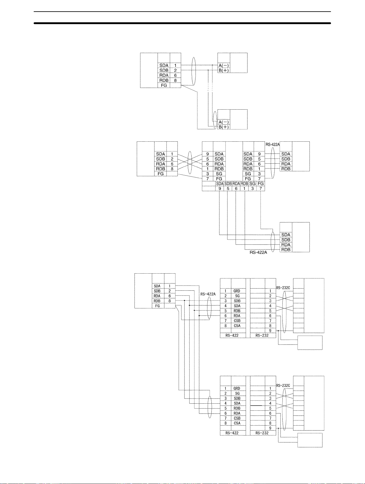
1:N Connections Using RS-422A/485 Ports
Serial Communications Board
RS-422A/
485 interface
Terminating resistance ON
4-wire
Serial Communications Board
RS-422A/
485 Interface
Terminating resistance ON
4-wire
Signal Pin
Hood
D-sub, 9-pin
connector (male)
Signal
Pin
Hood
D-sub, 9-pin
connector (male)
Device supporting RS-422A/485
communications (2-wire)
Signal
RS-422A/
485 interface
Device supporting
RS-422A/485
communications
(2-wire)
Signal
RS-422A/
485 interface
3G2A9-AL001
Pin
Signal
Pin
Signal
RS-422A/
485 interface
Signal
Pin
Shield
Device supporting
RS-422A/485
communications
Shield
(4-wire)
Signal
D-sub, 9-pin
connector (male)
Device supporting
RS-422A/485
communications
(4-wire)
Signal
RS-422A/
485 interface
RS-422A/
485 interface
5-4SectionUsing Protocol Macros
Serial Communications Board
Pin
Signal
RS-422A/
485 Interface
Hood
D-sub, 9-pin connector (male)
Terminating resistance ON
4-wire
DIP Switch
Pin 1: ON
Pin 2: ON (terminating
resistance)
Pin 3: OFF
Pin 4: OFF
Pin 5: OFF
Pin 6: ON
Shield
Shield
NT-AL001-E Link Adapter
Pin Signal
DIP Switch
Pin 2: OFF,
otherwise
same as below.
Signal Pin
NC
SD
RD
RTS
CTS
5V
DSR
DTR
SG
D-sub, 9-pin connector (male)
NT-AL001-E Link Adapter
Signal PinPin Signal
NC
SD
RD
RTS
CTS
5V
DSR
DTR
SG
Terminal block
D-sub, 9-pin
connector
(male)
Shield
Shield
Signal
FG
SD
RD
RTS
CTS
DSR
DTR
SG
(+) 5-V
(–) power
Signal
FG
SD
RD
RTS
CTS
DSR
DTR
SG
RS-232C
Interface
RS-232C
Interface
(+) 5-V
(–) power
75
Page 87

5-5 Protocol Structure
Protocols consist of communications sequences. A sequence consists of steps.
These steps can be repeated, or they can be branched or ended depending on
the responses received. A step consists of a command, send/receive messages, processing results, and the next process (which depends on the processing results).
Protocol
Messages
Communications
sequence
Step 0
Step 1
5-5SectionUsing Protocol Macros
Example: Reading the process values
for a Temperature Controller
Transmission of process value reading message and
reception of response message
CPU Unit
Serial Communications Board
A protocol consists of processing sequences (such as reading the process value
for a Temperature Controller) for a general-purpose external device. A sequence consists of a group of steps, each of which consists of a send/receive/
control command, send/receive message, processing result, and a next step
that depends on the processing results.
For example, with a sequence that reads the process value for a Temperature
Controller, the sequence sends the send message for the connected Temperature Controller (a character string in which the Process Value Read command is
inserted between the header + address and the check code + terminator) and
receives the receive message (a character string in which the Process Value
Read command response is inserted between the header + address and the
check code + terminator).
Command
Send message (Example: PROCESS VALUE READ command)
SEND
Header Address Send data Check
Receive message (Example: Response)
RECEIVE
Header Address Send data Check
code
code
Terminator
RS-232C or
RS-422A/485
Terminator
76
General-purpose external device
Page 88

5-5SectionUsing Protocol Macros
Depending on the response received, the user can either choose to resend the
same send message (retry processing), or to perform the next process (for example, read the process value for a Temperature Controller with a different address).
One protocol
Sequence No. 000 to 999
(60 sequences max./protocol)
Transmission
control parameter
Link word setting
Send/receive
processing
monitoring time
Response
notification method
Message list (see note 2)
Send message list
Header Address Terminator
Receive message list
Header Address TerminatorData Check
Reception matrix list (see note 2)
Reception matrix
Case No. 15
Step 0
Step 1
15 steps max.
15 steps max.
Data Check
Step 0
Step 1
One-step structure
With the SEND, RECEIVE, or
SEND&RECEIVE command
Command (see Note 1)
Messages (see note 2)
Normal end
Repeated
Y
Next process
Next step
To specified step
Sequence end
Sequence interrupt
N (error)
N (no)
(See
Y
note 3.)
Retry?
N (no)
Error processing
Case No. 00
Receive message
Sequence Parameters
Next process
Note 1. The SEND, RECEIVE, or SEND&RECEIVE commands can be used.
2. Three types of reception matrix are available for switching the processing,
depending on whether the messages are send messages, receive (wait)
messages, or multiple receive (wait) messages. Unlike sequences, these
matrixes are managed as lists.
3. Retries are possible on for the SEND&RECEIVE command.
Parameter Meaning
Transmission control
parameters
Link words Settings for shared words between the PC and the
Monitoring time Monitoring time for send/receive processing
Response notification method Timing for writing received data to I/O memory in
Control methods, such as flow control
Serial Communications Board.
the PC
77
Page 89

5-5SectionUsing Protocol Macros
Step Parameters
Parameter Meaning
Command One of the following: SEND, RECEIVE, or
SEND&RECEIVE
Messages
Repeat counter The number of times to repeat the step (0 to 255). The
Retry count Used for SEND&RECEIVE to retry the command for errors
Send wait time Used for SEND or SEND&RECEIVE to create a wait time
Response write
enable (for operand
specification)
Next process Specifies the next step or to end the sequence when the
Error processing Specifies the next step or to end the sequence when the
Send message The message sent for SEND.
Receive
message
Send message
and receive
message
Reception
matrix
repeat counter can be used to change send/receive
messages.
(0 to 9).
before sending data.
Specification of whether or not to write the received data to
memory.
current step is completed normally.
current step ends in an error.
The expected message for RECEIVE.
The message sent and the expected
message for SEND&RECEIVE.
A group of expected messages that can
be used to switch to different next
processes when RECEIVE or
SEND&RECEIVE is used.
Standard System Protocol Example
Process Value Read Sequence for E5
Level Item Setting
Sequence
Steps
Link words --Transmission control
parameters
Response notification
method
Reception wait time Tr 3 s
Reception finished wait
time Tfr
Send finished wait time
Tfs
Step number 00
Repeat counter Reset/001
Command SEND&RECEIVE
Retry count 3
Send wait time --Send message SD (00) _1
Receive message RV (00) _1
Response write enable Write
Next process End
Error process Abort
K Controller Read Protocol
Modem control
Scan
3 s
3 s
78
Page 90

Level SettingItem
Send message
SD (00) _1
SD (00) _1
Receive message
RV (00) _1
RV (00) _1
5-5SectionUsing Protocol Macros
Header <h> “@”
Terminator <t> [2A0D]
Error check code <c> LRC (horizontal parity) (0) (2 bytes of ASCII)
Length <l> --Address <a> $ (R (1) ) ,2)
Message edited <h> + <a> + “1” + “00” + “0000” + <c> + <t>
Data
Header <h> “@”
Terminator <t> [2A0D]
Error check code <c> LRC (horizontal parity) (0) (2 bytes of ASCII)
Length <l> --Address <a> & (R (1) ) ,2)
Message edited <h> + <a> + “00” + “00” + & (W (1) ,4) + <c> + <t>
Data
Handling
Communications
Problems for Standard
System Protocols
The CQM1H-series PCs provide standard system protocols to enable communications with OMRON components without having to create communications
sequences. The sequences in the standard system protocols can be executed
merely by setting operands for the PMCR(––) instruction.
Processing for communications line problems during communications for the
standard system protocols are set to normal settings, as shown in the following
table. If these settings are not suitable to the application or if improvements are
desired, use the CX-Protocol to modify the following settings in the required sequences. For details on the use of the CX-Protocol, refer to the CX-Protocol Op-
eration Manual (W344). Refer to the appendices for the settings in the standard
system protocols.
Level Item Possible changes in settings
Sequence
parameters
Step
parameters
Link words
Transmission control
parameters
Response
notification method
Reception wait time
Tr
Reception finished
wait time Tfr
Send finished wait
time Tfs
Repeat counter
Command
Retry count The retry count is general set to 3 retries (4
Send wait time
Send message
Receive message
Response write
enable
Next process
Error process
No reason to change.
The monitoring times are set to 3 seconds
for most sequences. The settings are
different for send-only and receive-only
sequences, as well as for sequences that
require time for responses.
No reason to change.
tries total) for sequences that use the
SEND&RECEIVE command. Different
settings are used for sequences that have
other commands.
No reason to change.
79
Page 91

5-6 Control Bits, Flags, and Status Information
Control bits, flags, and status information for the Serial Communications Board
are available in the Inner Board Slot 1 area. The addresses in this area are as
follows:
Inner Board Slot 1 Area: IR 200 to IR 207
All of the bits in the following table are initialized (cleared) when power to the PC
is turned ON, when the mode is changed between PROGRAM and RUN/MONITOR mode, when the STUP(––) instruction is executed to change the serial
communications mode, or when the communications port is restarted. The bits
are also reset at the timing indicated in the Reset column in the table.
5-6SectionUsing Protocol Macros
Word Bits Name and Function Classifi-
cation
IR 200
00 Serial Communications Board Hardware Error Flag
Turns ON if an error occurs in the Board. Replace the
Board if this flag will not turn OFF even after remounting
the Board securely or mounting it in a different CPU Unit.
01 Board Identification Error Flag (hardware error)
Replace the Board if this flag turns ON.
02 Protocol Data Error Flag
This flag turns ON if an error is detected in the protocol
data checksum when the power is turned ON. The ERR
indicator on the CPU Unit will also flash and the RDY indicator will flash.
This error may occur if the communications connector becomes disconnected or the PC power is turned OFF during protocol data transfer. Use the CX-Protocol to transfer
of the protocol data again.
11 Port 2 Protocol Macro Execution Error Flag
The flag turns ON when the protocol macros are not
supported (error code 1), there is a sequence number
error (error code 2), an attempt was made to write data
receive data at an illegal address (error code 3), or a
protocol data syntax error occurred (error code 4).
12 Port 1 Protocol Macro Execution Error Flag
Same as IR 20011.
13
14
15
PC Setup Error Flags
Bit 15 turns ON if a Setup error occurs in the PC Setup
settings for the Board.
Bit 14 will turn ON if the error is for port 1.
Bit 13 will turn ON if the error is for port 2.
Bit 13 will turn ON if the error is for port 2.
Correct the PC Setup.
The defaults will be used for the settings causing th error.
System
error
Set Reset
When error
occurs
Power ON
Normal
completion
of protocol
data
transfer
Start of
sequence
Power ON
80
Page 92

5-6SectionUsing Protocol Macros
Word ResetSetClassifi-
IR 201
IR 202 00 to 07 Port 1 Repeat Counter PV (00 to FF hexadecimal)
IR 203 00 to 07 Port 2 Repeat Counter PV (00 to FF hexadecimal)
00 to 03 Port 1 Error Code (Transmission Error Status)
When an error occurs during transmissions for a protocol
macro, an error code will be output to these bits.
0: Normal operation 1: Parity error 2: Framing error
Error codes 3 to 7 are not possible for protocol macros.
These error codes are the same regardless of the serial
communications mode.
IR 20104 will also turn ON except when the error code
contains all zeros. SEND&RECEIVE retry processing will
be performed for any error.
If communications are recovered through protocol macro
retry processing, the error code will be cleared, but will be
maintained even if a different error occurs during the retry.
04 Port 1 Communications Error Flag
This flag turns ON when an error occurs in the
communications path between the communications port
and the external device or when communications
parameters are not set correctly.
The operation of this flag is the same regardless of the
serial communications mode.
Details on the error are output as an error code to
IR 20100 to IR 20103.
07 Port 1 Sequence Abort Completion Flag
This flag turns ON when a sequence has been aborted due
to ABORT in the next process or in the error process. It will
be OFF if an abort has not occurred.
08 to 11 Port 2 Error Code (Transmission Error Status)
Same as bits IR 20100 to IR 20103, but works together
with IR 20112.
12 Port 2 Communications Error Flag
Same as bits IR 2014, but works together with IR 20108 to
IR 20111.
15 Port 2 Sequence Abort Completion Flag
Save as IR 20107.
The repeat counter variable N is set. The value is cleared
when the sequence execution starts.
The present value N varies according to the method used
to initialize the value. For resets, the variable N is set to 0
when the step is started, and the step is executed according to the set number of times. For holds, the variable N for
the present value is held when the step is started, and the
step is executed according to the set number of times.
If the Repeat Counter Setting Value is set to read word
R ( ), and 0 is read, then 0 will be stored and this step will
be skipped (the next process setting will be ignored), and
the sequence will move to the next step (+ 1). For details,
refer to the CX-Protocol Operation Manual (W344).
Same as IR 20200 to IR 20207.
Name and FunctionBits
cation
Transmission error
Sequence
status
Transmission error
Sequence
status
Sequence
status
When error
occurs
When
sequence is
aborted
When error
occurs
When
sequence is
aborted
When
repeat
count is
refreshed
Start of
sequence
81
Page 93

5-6SectionUsing Protocol Macros
Word ResetSetClassifi-
IR 204
IR 205
IR 206
IR 205 15 IR 204 Port 2 Data Stored Flag
00 Port 1 Tracing Flag
According to instructions from the CX-Protocol, this flag is
turned ON while time-series data for send and receive
messages is being traced.
01 Port 2 Tracing Flag
Same as IR 20400.
08 to 11 Port 1 Protocol Macro Error Code
The list of error codes is provided at the end of this table
on page 85.
If error code 1, 2, 3, or 4 is stored, the Port 1 Protocol
Macro Execution Error Flag (IR 20111) will be turned ON,
the ERR/ALM indicator on the CPU Unit will flash, and a
non-fatal error will occur.
When an error occurs, the error code is held until the next
sequence starts.
The error must be cleared from a Programming Console or
other Programming Device after the cause of the error has
been eliminated.
12 to 15 Port 2 Protocol Macro Error Code
Same as IR 20408 to IR 20411, but works together with
IR 20112.
00 to 03 Port 1 Executed Reception Case No. (code)
Reception matrix case numbers 0 to 15 (0 to F hex) are
stored for which reception has been completed. The number is cleared when the sequence execution starts.
The Executed Reception Case No. is stored only when the
reception matrix is set using the RECEIVE or SEND&RECEIVE command. If a reception matrix is not set, the case
number will be set to 0 (cleared) when another command
is executed.
04 to 07 Port 1 Completed Step Number
Step numbers 0 to 15 (0 to F hex) are stored for the steps
for which execution has been completed.
15 IR 204 Port 1 Data Stored Flag
0: No data stored; 1: Data stored in IR 20408 to IR 20411
00 to 03 Port 2 Executed Reception Case No. (code)
Same as IR 20500 to IR 20503.
04 to 07 Port 2 Completed Step Number
Same as IR 20504 to IR 20507.
0: No data stored; 1: Data stored in IR 20412 to IR 20415
Name and FunctionBits
cation
Tracing Start of
Protocol
macro
status
Sequence
status
Protocol
macro
Sequence
status
Protocol
macro
trace
When error
occurs
When
matrix is
received
When step
is executed
When error
occurs
When
matrix is
received
When step
is executed
When error
occurs
Start of
sequence or
end of trace
Start of
sequence
82
Page 94

5-6SectionUsing Protocol Macros
Word ResetSetClassifi-
IR 207
00 Port 1 Restart Bit
The communications port will be restarted when this bit is
turned ON by the user.
01 Port 2 Restart Bit
Same as IR 20700.
02 Port 1 Continuous Trace Start/Stop Bit
The CX-Protocol will start a continuous trace when the bit
is turned ON. The trace is ended when the bit is turned
OFF.
The CPU Unit will manipulate the Shot Trace Bit and
Continuous Trace Bit when trace operations are performed
from the CX-Protocol. Do not manipulate these bits directly
from a ladder diagram.
03 Port 2 Continuous Trace Start/Stop Bit
Same as IR 20702.
04 Port 1 Shot Trace Start/Stop Bit
The CX-Protocol will start a one-shot trace when the bit is
turned ON. The trace is ended when the bit is turned OFF.
The Serial Communications Board will be cleared when
the trace buffer becomes full.
The CPU Unit will manipulate the Shot Trace Bit and
Continuous Trace Bit when trace operations are performed
from the CX-Protocol. Do not manipulate these bits directly
from a ladder diagram.
05 Port 2 Shot Trace Start/Stop Bit
Same as IR 20704.
Name and FunctionBits
cation
Port status
Tracing From
User-set or
STUP(––)
CX-Protocol
After
settings are
changed
and port
restarted
From
CX-Protocol
At end of
short trace
83
Page 95

5-6SectionUsing Protocol Macros
Word ResetSetClassifi-
IR 207
08 Port 1 Protocol Macro Executing Flag (instruction
execution)
This flag is turned ON when a PMCR(––) instruction (se-
quence) is executed. The flag will remain OFF if execution
fails.
When the sequence is completed and receive data is written, the flag is turned OFF after all the receive data has
been written to I/O memory.
This flag is turned OFF when the sequence is completed
(either when it is ended by End, or when it is ended by
Abort).
When the scan response notification method is set for the
sequence, first a check is made to see if the received data
has been written to I/O memory before the Protocol Macro
Executing Flag is turned OFF.
09 Port 1 Transfer Step Error Processing Flag
This flag is turned ON when a step has ended abnormally.
It is turned OFF if the step ends normally as a result of a
retry.
1: Step ended abnormally
0: Step ended normally
10 Port 1 Sequence END Completion Flag
This flag is turned ON when a sequence is completed for
the next process or for an error process with an END command.
Setting END when a sequence has ended normally and
setting ABORT when the sequence has ended abnormally
enables this flag to be used to determine whether or not
the sequence execution has ended normally.
1: Sequence ended
0: Sequence not ended
11 Port 1 Forced Abort Bit
Protocol processing will be aborted when this bit is turned
ON. (Processing may be completed if the bit is turned ON
too late.)
12 Port 2 Protocol Macro Executing Flag (instruction
execution)
Same as IR 20708.
13 Port 2 Transfer Step Error Processing Flag
Same as IR 20709.
14 Port 2 Sequence END Completion Flag
Same as IR 20710.
15 Port 2 Forced Abort Bit
Same as IR 20711.
Name and FunctionBits
cation
Protocol
macro
status
Step error At compare
Sequence
status
Abort
processing
Protocol
macro
status
Step error At compare
Sequence
status
Abort
processing
At
instruction
execution
error after
reception
End of
sequence
User-set User-set
At
instruction
execution
error after
reception
End of
sequence
User-set User-reset
At
completion
of execution
Start of
sequence
At
completion
of execution
Start of
sequence
84
Page 96

Error Codes
The contents of the error codes are shown in the following table.
Code Error contents Protocol macro
execution
0 No error Executed
2 Sequence Number Error
The sequence number specified by the
PMCR(––) instruction does not exist in the
Board.
3 Receive Data/Write Area Exceeded Error
When data is written or read to the CPU Unit, the
specified area range was exceeded.
4 Protocol Data Syntax Error
A code that cannot be executed occurs while the
protocol macro was executed. (Example: A
header occurs after a terminator.)
5 Protocol Macro Execution Error During Port
Initialization
This error occurs when the PMCR instruction is
executed while the port is being initialized (i.e.,
while the serial communications port is being
restarted or while the serial communications
mode in the PC Setup of the Serial
Communications Board is being modified using
the STUP instruction or the Programming
Device).
Not executed
Execution stops after
the error occurs.
Execution stops after
the error occurs.
5-7SectionUsing Protocol Macros
5-7 Using Protocol Macros
5-7-1 Executing Communications Sequences
Use the PMCR(––) instruction to execute communications sequences.
PMCR(––) Instruction Specifications
Control Data: C
15 00
C:
Digits 2 to 4 (bits 00 to 11):
Communications sequence number (000 to 999)
Digit 1 (bits 12 to 15): Port specifier
1: Port 1 (RS-232C)
2: Port 2 (RS-422A/485)
First Send Data Word: S
15 00
S
S+1
:
:
S+n
S specifies the first word of the words containing the data required for sending.
Number of send words
Send data
:
:
Control data
First send word
First receive data storage word
Total number of words including S
85
Page 97

5-7SectionUsing Protocol Macros
The number of send words in S+1 and the following words is stored in S. The
setting range is 0001 to 0129 (4 digits BCD). S is also included in the number of
words.
Note When there is no send data, set S to #0000. If any other constant or a word ad-
dress is set, an error will occur, the Error Flag (SR 25503) will turn ON, and
PMCR(––) will not be executed.
First Receive Data
Storage Word (D)
D specifies the first word of the area used to store the receive data.
If a word address is specified for D and a response is requested, the data
through the highest location received in the reception buffer will be stored in
memory starting at D+1. The number of words that was stored starting at D+1
will be stored in D. D is included in the number of words.
15 00
D
D+1
:
:
D+n
Number of receive words
Receive data
:
:
Total number of
words including D
The number of words of receive data in D+1 and the following words is stored in
D. The range is 0001 to 0129 (4 digits BCD). D is also included in the number of
words.
Note When there is no receive data, set D to to a dummy word address. If any constant
is set, an error will occur, the Error Flag (SR 25503) will turn ON, and PMCR(––)
will not be executed.
PMCR(––) Operation
Flags
86
When PMCR(––) is executed, the communications sequence specified in bits
00 to 11 of C is executed for the port specified in bits 12 to 15 of C (port 1 or 2).
If an operand is specified as a variable in the send message, data starting in S+1
for the number of words specified in S is used as the send data. If an operand is
specified as a variable in the receive message, data will be received in words
starting from D+1 and the number of words of received data will be automatically
stored in D.
Name Address ON OFF
Error Flag SR 25503 Indirectly addressed DM or EM word is
non-existent. (Content of DM/EM word is
not BCD, or the area boundary has been
exceeded.)
Another PMCR(––) instruction was already in
progress when the instruction was executed
(IR 20708 or IR 20712 is ON).
The port specifier was not 1 or 2.
Note: PMCR(––) will not be executed when
SR 25503 is ON.
Other
times.
Page 98

Operand Areas and Address Ranges
Area C S D
IR and SR Areas IR 000 to IR 255 IR 000 to IR 252
HR Area HR 00 to HR 99
AR Area AR 00 to AR 27
LR Area LR 00 to LR 63
Timer and
Counter Area
Data Memory
(DM) Area
Extended Data
Memory (EM)
Area
Indirect DM
address
Indirect EM
address
Constant Area See description of
5-7-2 Ladder Program Structure
5-7SectionUsing Protocol Macros
TIM/CNT000 to TIM/CNT511
DM 0000 to DM 6655 DM 0000 to
DM 6143
EM 0000 to EM 6143
*DM 0000 to *DM 6655
*EM 0000 to *EM 6143
#0000 to #FFFF ---
control data.
Programming Example
When creating a ladder program, note the following points.
• To ensure that a PMCR(––) instruction is not executed while another
PMCR(––) instruction is being executed, use the Protocol Macro Executing
Flag in an NC input condition.
• Use an OFF condition for the Protocol Macro Executing Flag and perform processing to read the results of sequence execution, or perform processing
when a sequence ends in an error.
Protocol Macro
Input condition
20708
A
Executing Flag
20708
PMCR
DIFD (14) A
Reading of sequence execution results
Processing of sequence errors
87
Page 99

5-7-3 Ladder Program Example
The following diagram shows an example in which sequence number 000 (Present Value Read) for a Temperature Controller (E5K Read Protocol) is
executed using the protocol for an OMRON Temperature Controller connected
to port 2 (RS-422A/485) of a Serial Communications Board.
Connections
Serial Communications Board
5-7SectionUsing Protocol Macros
32 Units max.
Port 2
RS-422A/485
Send data
Receive data
Temperature
Controller E5K
Unit No. 00
Specifies the Temperature Controller Unit No. ,
sends the PRESENT VALUE READ command
send data, and receives the present value set
in the response in the specified word.
Temperature
Controller E5K
Unit No. 01
32 Units max.
Send Word Allocation for Sequence No. 000 (Present Value Read)
First word of
send data
Number of send data words Contents (data format) Data
S + 1 S
(Undefined) Unit No. Number of send data words
WordS
S + 1
(4-digit BCD)
Unit No.
(2-digit BCD)
Receive Word Allocation for Sequence No. 000 (Present Value Read)
Receive data
storage words
Number of receive data words Contents (data format) Data
D + 1 D
Present value Number of receive data words
WordD
(4-digit BCD)
Temperature
Controller E5K
Unit No. 31
0002 (fixed)
00 to 31
0002
88
D + 1
Present value
(4-digit BCD)
Scaling
Lower limit to upper limit
Page 100

5-7SectionUsing Protocol Macros
Operand Settings for the
PMCR(––) Instruction
PMCR
#0000
D00100
D00200
Reading the present value of E5K Unit No. 03 and storing it in DM 0201
C: Control data
1000
Port 1
S: First send data word
S: DM 0100
S+1: DM 0101
D: First receive data storage word
D: DM 0200
D+1: DM 0201
0000: Sequence No. 000
Number of send data words = 2
Unit No. = 03
Present value
Number of receive data words = 2
Present value is stored.
(4-digit BCD)
89
 Loading...