

Page 1
Programmable Automation Controllers
CJ2SERIES
Introducing the Flagship CJ2 CPU Units, with Built-in
Multifunctional EtherNet Port
Built-in EtherNet/IP ports
Tag based programming
Fast processing time
Large memory capacity
Fully compatible with CJ1 modules
Page 2

CJ2 – Omron’s New Small, Fast & Flexible
Modular Flagship PAC, with built-in
EtherNet/IP and Tag Based Programming
The CJ2 Programmable Automation Controller (PAC) delivers PAC features and capabilities as
defined by ARC Advisory Group in Omron’s popular, compact modular CJ PLC platform.
Multi-domain functionality – CJ2 performs logic, motion, HMI and process control on a single platform.
Single multi-discipline development platform - Using a common tag database, PAC and HMI
programming can be developed in parallel, reducing development time. Omron’s CJ2 PAC, NS-Series
HMI’s and middleware all share the same tag database. CX-One Software incorporates 16 different
development tools.
Software tools that allow access across several machines - Omron’s CJ2 PACs supports Single
Point Multiple Access (SPMA) which enables set-up and programming of all local modules and remotely
networked modules.
Open, modular architecture - Omron’s CJ2 supports the capability to handle logic, position & motion
control, RFID, analog and temperature control, HMI, bar code, networking modules, communication
modules, smart sensors, vision and drives, all in a single modular platform.
Standardized Programming & Open Networks - Omron’s CJ2 supports all IEC61131-3 programming
languages: Ladder, Function Block, Structured Text, Sequential Function Chart (SFC) and Instruction List.
Open networks enable seamless communications using these protocols: Ethernet, EtherNet/IP, DeviceNet,
CompoNet, PROFIBUS, PROFINET, FLNet, MECHATROLINK-II and Serial (RS-232C, RS-422, RS-485).
CJ2 CPU’s – Offer built-in EtherNet/IP networking, High-speed, high-capacity data exchange between
PAC’s, PLC’s, HMI’s and I/O devices. EtherNet/IP can be used to perform both information and control
Networking, share up to 184,832 words over 256 nodes. CJ2 PAC’s can easily connect to Rockwell’s
ControlLogix and CompactLogix PLC’s using EtherNet/IP tag data links.
2
Page 3
Key Features and Benefits
Large Memory Capacity –
The CPU program memory capacity has been
increased up to 400K Steps, DM has increased
up to 800K while Function Block Program,
Symbol, Comment Memory has increased to
3.5MB. Large memory allows for larger more
versatile programs, well documented programs
makes it easier and faster to troubleshoot.
Fast –
Processing times are significantly faster. Faster
production, faster development time, faster time
to market and higher throughput means higher
speed applications can be achieved.
One Single Programming
IEC61131-3 Programming –
All 5 programming languages are supported
with the CJ2 PAC. Ladder, Function Block,
Structured Text, Instruction List and Sequential
Function Chart. Hundreds of Pre-built pre-test
Function blocks significantly can reduce design
time. Standard programming languages allow
for fast, flexible and powerful programming.
General-purpose Networks
for Support Software
Interface –
CX-One software applications can be easily
connected using standard USB and EtherNet
Cables via USB and EtherNet/IP ports.
Environment –
CX-One is Omron’s single programming
environment for PAC’s, PLC’s, HMI, Networks,
Process Control, Motion Control and Simulation
Software. Legacy PLC’s are supported and single
click conversion to new hardware makes for easy
migration. The software includes and Update service
that automatically checks for the latest update of
software.
Improved Debugging –
Online editing and data tracing have been
improved, greatly increasing the efficiency of
debugging. The data trace function is built into the
PAC and can monitor & store I/O and data in 1
ms time increments. This allows for easy and faster
debug time, which allows for faster time to market.
Tag Based Programming –
CJ2 CPU Units have a tag name server to
manage tag names and I/O addresses.
This enables access from external devices
using tag names, without needing to know the
I/O addresses.
CJ2 Capabilities –
Offers functions such as motion control, process
control, RFID, Logic and Drives all on the same
controller platform. The modular architecture is
ideal for applications where the user is interested
in saving money by reducing development time &
increasing production.
3
Page 4
Faster and Higher-capacity CPU Units
High-capacity data memory is in demand to meet the need for quality control for equipment and
products and to provide real-time processing and collection of measurement data. Large program
capacity is also in demand due to the need for improving program reusability through modularization
and structured programming.
Great Expanded Program Capacity and Data Memory Capacity
Ample capacity is provided for the data required for control operations.
The High-capacity CJ2H-CPU68-EIP Is Now Available.
» Program capacity: 400 Ksteps (1.6 times larger than before)
» Data memory capacity: 832 Kwords (2 times larger than before)
» Basic Instructions (0.016 µs)
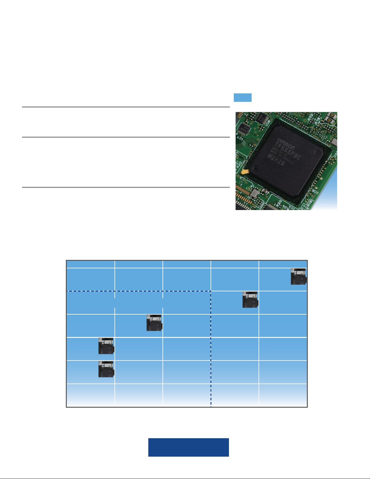
And, All CJ2 Models Have more Capacity than CJ1 Models.
In addition, all models have more capacity than the equivalent CJ1series models to meet needs for structured programming and increasing
amounts of data.
Increased Capacity over CJ1-series CPU Units
Program capacity
400 Ksteps
CJ2-H
250 Ksteps
NEW
CPU68-EIP
CJ1 Product Lineup
150 Ksteps
CPU66-EIP
100 Ksteps
CPU65-EIP
50 Ksteps
CPU64-EIP
30 Ksteps
64 Kwords 160 Kwords 352 Kwords 448 Kwords 512 Kwords 832 Kwords
Program capacity: 400 Ksteps
Data memory capacity: 832 Kwords
4
CPU67-EIP
Data memory capacity
Page 5
High-speed System I/O Throughput
NEW
Improved basic performance enables fl exible
machine control.
Ample Instruction Execution Performance
for Machine Control
The CJ2 Series fully responds to customer
requests for improvement and
increased information.
» System Overhead
Common processing 200 µs
Interrupt response: 30 µs
» Basic Instructions
LD instruction execution: 0.016 µs
OUT instruction execution: 0.016 µs
» Floating-point Math
SIN calculation: 0.59 µs
Floating-point decimal addition and
subtraction: 0.24 µs
Faster I/O Refreshing Using the Burst
2.4
2.4
Times
X
800 µs
Transfer Method
I/O refreshing between an EtherNet/IP Unit and
the CPU Unit is now performed at high speed
using the even faster and higher-capacity data
links for EtherNet/IP. This method is standard
for the CJ2 CPU Units. I/O refreshing is now
performed at up to 2.4 times the speed of
previous Communications Units.
I
/O refresh speed
(for 1,000 words)
CJ2
CJ1
330µs
Burst transfer
High-speed, high-capacity
20
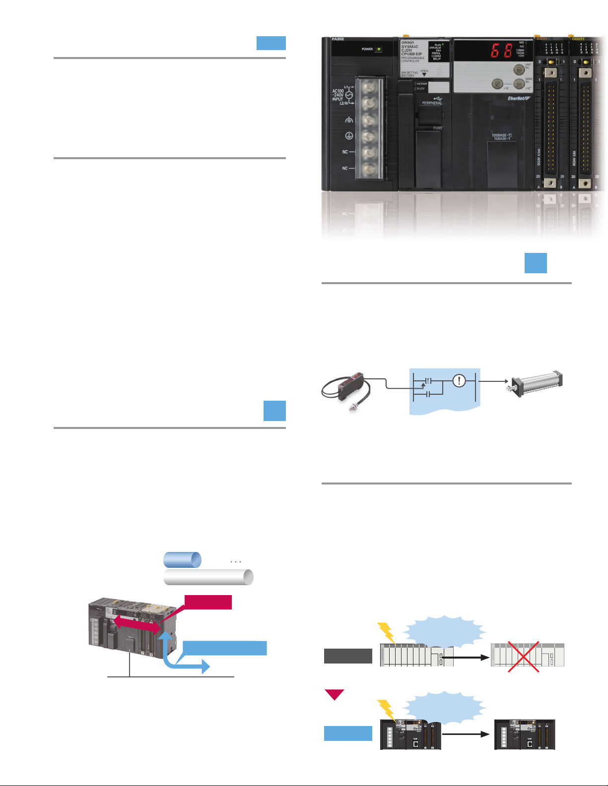
Faster Immediate I/O Refreshing
Times
Immediate refreshing of basic I/O is also faster.
Real-time inputs and outputs while instructions
are being executed are up to 20 times faster
than before.
(Example: !LD instruction speed improved from 20 µs to 1 µs)
Air cylinder
Fiber Sensor
E3X-DA
Sensor status is read
just prior to instruction
execution.
CJ2 CPU
Output immediately
after instruction is
executed
Automatic User Memory Recovery
Finer memory production processes have been
accompanied by problems such as bit corruption
caused by cosmic rays. With the CJ2 CPU Units,
corruption in the user program is detected and the
program recovered in real time before program
execution. This reduces equipment down time by
minimizing the number of times that operation is
stopped due to memory errors.
Cosmic rays
User program
data is corrupted
Previously
Operation is stopped due
to memory error.
EtherNet/IP
» I/O Refreshing
16-point Basic I/O Unit: 1.4 µs
8-point Analog Input Unit: 50 µs
Cosmic rays
(Thermal neutrons)
CJ2
User program
data is corrupted
Data is automatically
restored and normal
operation continues.
5
Page 6
Networks Are More Open
EtherNet/IP is an open network that uses the TCP/IP protocol on EtherNet networks, which are widely used
in offi ces and factories throughout the world. The CJ2 CPU Units support EtherNet/IP as a standard feature.
Because EtherNet/IP uses TCP/IP, it provides the many advantages of EtherNet technology.
Universal EtherNet and FA Data Links Can Be Used at the Same Time.
NEW
With EtherNet/IP, One Port Is Enough.
FTP Communications, Data Links, and Support Software Can Be Used Simultaneously through
a Single Port.
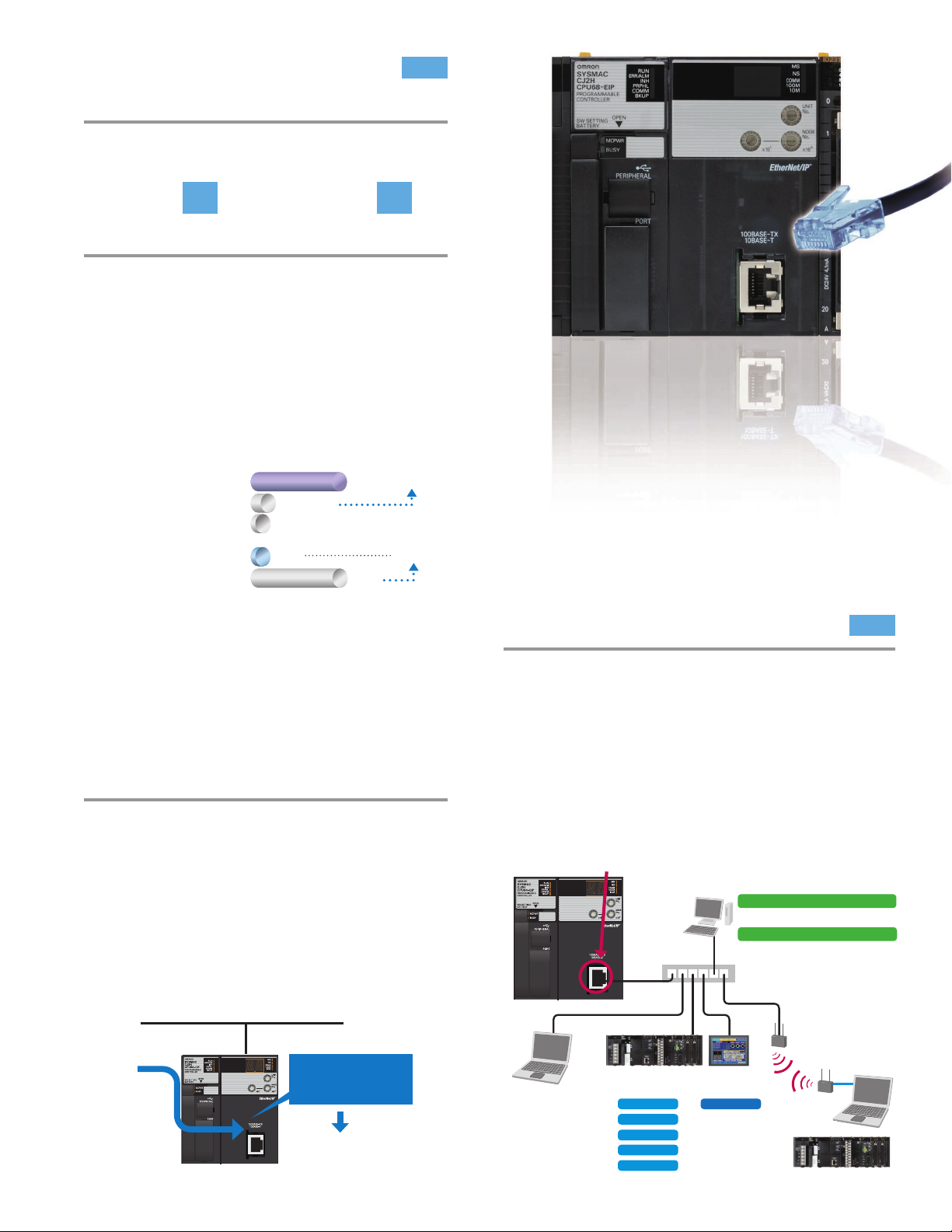
The CJ2 CPU Units provide as standard equipment a multifunctional EtherNet port that supports EtherNet/
IP. There is no need to add an EtherNet Unit, because universal EtherNet communications, such as data links
between PAC’s, message communications between PAC’s, and FTP transfers, are all enabled simultaneously
through this one port while Support Software is connected.
Programmable Terminal
Host application
EtherNet/IP
HUB
Message
communications
CJ2 CPU
Message
communications
Data links
CJ2 CPU CJ1-EtherNet/IP Unit
FTP
Data links
CX-One
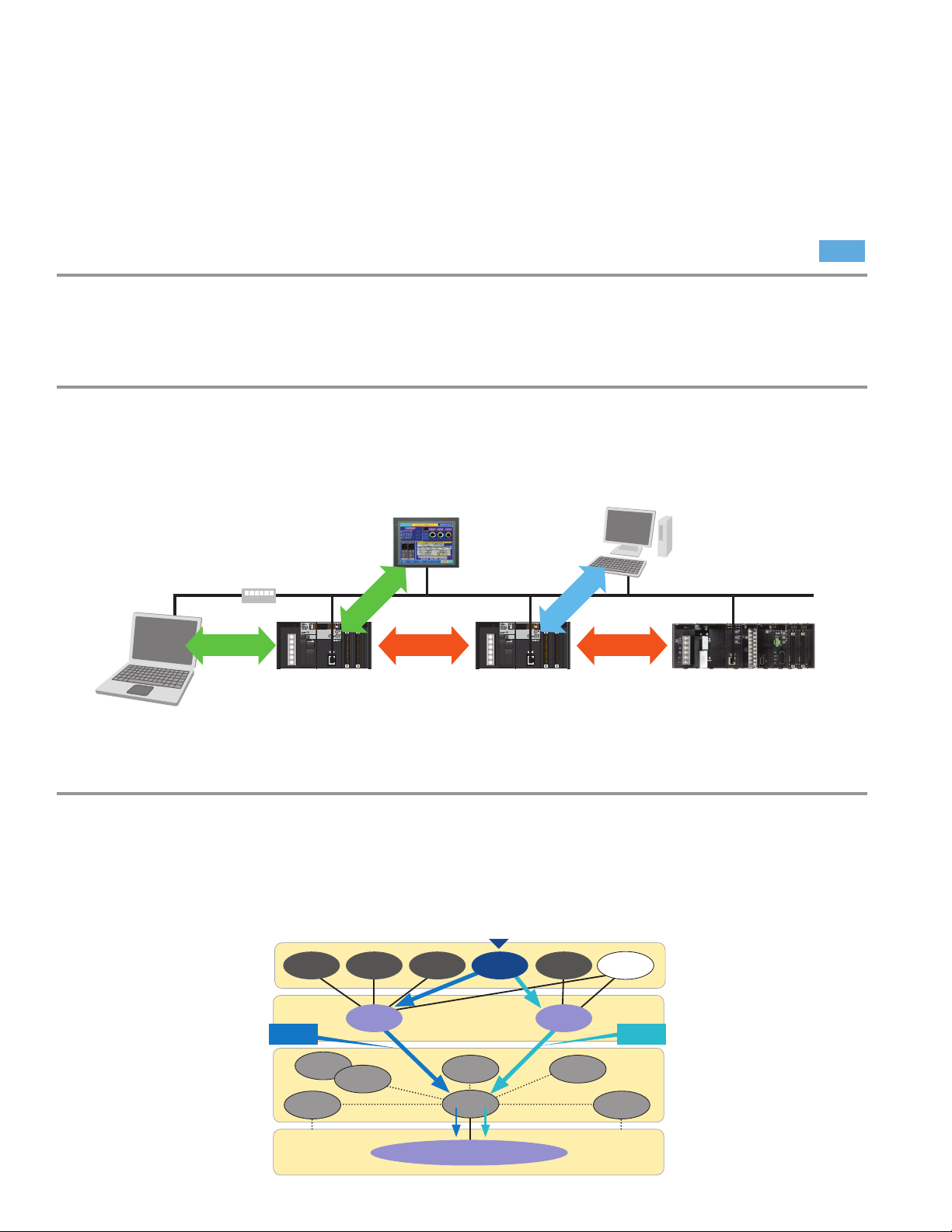
Create a Seamless Data Flow in a Single Network System.
Because it is based on the world-standard CIP open protocol, a seamless data fl ow can be achieved between
control lines and information monitoring lines in a single network system. From here on, EtherNet/IP will be
increasingly used in multi-vendor environments (such as robotics and safety devices).
EtherNet/IP is an industrial network that uses the CIP real-time protocol in the EtherNet
application layer. (Standards: EN 50170 and IEC 61158)
Application
Layer
Transport
Layer
Network
Layer
Data Link
Physical Layer
FTP HTTP SMTP SNMP FINS
Explicit
Messages
OSPF
ARP RARP
TCP UDP
IGRP
IEEE 802.3 EtherNet
CIP
ICMP IGMP
IP
Rea l-ti me Dat a
Links
6
Page 7
Extremely Fast and High-capacity Data
NEW
Links Compared to Previous FA Networks
Large Data Transfers with High Reliability.
30
High-speed and High-capacity
Times
9
Times
Data Links
From manufacturing recipes and information
on interlocks between processes to production
data, any type of data can be exchanged
at high speed and at the optimal timing.
Communications performance is vastly
improved over OMRON’s Controller Link and
FL-net networks.
Data Link
Capacity (Total)
Data Link
Performance
(See note.)
EtherNet/IP
Controller Link
FL-net(OMRON)
EtherNet/IP
Controller Link
Note: Communications cycle time for 20,000 words
20,000 words
8,704 words
10ms 30X
180,000 words…
300ms
9X
Peripheral Devices (such as Cables, Hubs, and
Wireless Devices) Can Be Used With Universal
EtherNet Technology.
NEW
Automatic Address Allocation Is Expanded
to Up to 240 Kwords, Enabling Allocation of
Large Amounts of Data.
The memory size of the EM Area for automatic
address allocation in CX-Programmer symbol tables
has been expanded to a maximum of 240 Kwords.
When a tag is automatically allocated, data link
design and access from the host are enabled with
no need to be conscious of addresses. Moreover,
bits can be force-set/reset in the areas in which
data is automatically allocated.
EtherNet/IP
Tag access
CJ2 CPU Unit
Tags are automatically
allocated to the highcapacity EM Area.
Designing requires tag
names only, with no need to
worry about addresses.
The convenience of a global standard at your
fi ngertips.
» Using Universal EtherNet Reduces Network
Installation and Wiring Costs.
» FA Wireless LAN Makes Mobile Control Easy,
with No Need for Rewiring when
Changing Layout.
Built-in EtherNet/IP port on CPU Units
(multifunctional EtherNet port)
Host application
Easy Monitoring with Excel
CX- Reporter
PAC Access with Visual Basic/C#.NET
CX- Compolet
Switching hub
FA wireless
LAN WE70
Support Software
PLC
CJ1 or CJ2 CPU Unit
Data Links
FINS Messaging
CIP Messaging
FTP
Time Coordination
Programmable
Terminal NS Series
Tag Access
or
7
Page 8
No Need for Memory Map Control.
The CJ2 CPU Units introduce a new feature called tag access, to reduce your TCO (Total Cost of Ownership)
for systems that use Programmable Terminals, multiple PAC’s, and host applications. Tags allow freedom from
memory maps.
Simultaneous Development Takes the Stress Out of Short Deadlines.
NEW
No Need for Address Allocation Adjustments in Post-processing.
The various Controllers do not depend on addresses, so parallel development at each Controller is enabled
by first simply determining the tag names. There is no need for subsequent address allocation.
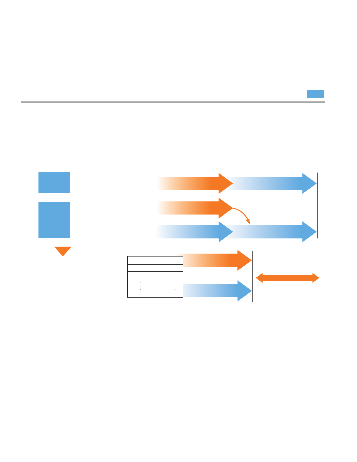
Example: Programmable Terminal and CJ2 Development
Previously
Case 1
Case 2
CJ2
By simply setting tag names, PAC and
Programmable Terminal programming
can be performed in parallel.
The PLC program is first
created, and then the ladder
program is referenced to
create the screens.
The screen graphics are
created in advance, and
then addresses are allocated
and checked after the ladder
program is completed.
Tag name
Number_produced
Production_target
Ladder program is created.
Ladder program is created.
Programmable Terminal screens are
created (graphics only).
Address
Undetermined
Undetermined
Ladder program is created.
Addresses are determined while
creating the ladder program.
The screens are created
Programmable Terminal screens
are created.
The addresses are set.
Addresses are allocated and
the allocations are checked.
Design time is shortened
» Simultaneous Development for Programmable
Terminal and CJ2 CPU Unit
Programmable Terminal screens can be designed
using tag names defined in the CJ2 CPU Unit. There
is no need to adjust address allocations in postprocessing.
» Data Links between CJ2 CPU Units
Simply setting tag names allows development to
proceed simultaneously among multiple designers
and multiple vendors. It is then easy to subsequently
change the sizes of data links.
8
The screens are created with no need
to pay attention to addresses.
» Simultaneous Development for Host Application
and CJ2 CPU Unit
Designing can be carried out simply by setting tag
names in the information section and the control
design section. There is no need for physical addresses in the network interface specifications.
Page 9
The Ease of Changing Designs Makes It
Simple to Add or Upgrade Equipment.
There is little effect on address changes.
Previously, when data was exchanged by
address specifi cation and addresses were
changed, the program had to be changed at
other Controllers and various operations, such as
memory checks, had to be performed. Now, tag
names eliminate the dependence on a memory
map and the need for checking items affected
by changes. This allows equipment to be easily
added or upgraded.
Programmable Terminal
NS Series
No change required.
Even after the change, the
number of items produced
is acquired correctly from
H200.
Number_produced
CJ2 CPU
Change
With the CX-Programmer, the address for the tag named “Number
produced” is changed from D100
to H200.
Accessed by tag name
Host application
No change required.
EtherNet/IP
Number_produced
tag name address
Number_produced
Number_produced
D100
H200
Change
Assurance of Quality, Free from Mistakes.
Tags can be shared among the CJ2 CPU Units,
NS-series PTs and Middleware. Tag names can
be shared among controllers that exchange
data using the CX-One or Excel import/export
functions. Because redundant address entry and
address allocation are not needed, checking is
also not required. This makes it easy to construct
high-quality systems.
What is Tag Access?
NEW
A tag is a name given to an address. Tags are
managed in the CJ2 CPU Unit, where they are
defi ned as network symbols. The common userdefi ned tag names are used from Programmable
Terminals and host applications to access memory
in a CJ2 CPU Unit without knowing the actual
memory address.
Programmable Terminal
NS Series
Programmable Terminal screen
Created using tag names.
Number_produced
Number_produced
Data links using tag names
Application
Developed using tag names.
Number_produced
Accessed by tag nameAccessed by tag name
PAC ladder program
Developed using tag names.
Host application
EtherNet/IP
Copy
&
Paste
CX-Programmer symbol table
CX-Programmer symbol tables can
be copied and pasted!
CX-Designer symbol table
CJ2 CPU
Tags are managed in the CJ2 CPU Unit as network symbols.
Symbol Table
Tag name
Number_produced
Production_target
Data link design
Allocated using tag names.
Physical address
D100
D200
CJ2 CPU CJ2 CPU
I/O Memory
Address
D100
D200
Data
&200
&500
9
Page 10
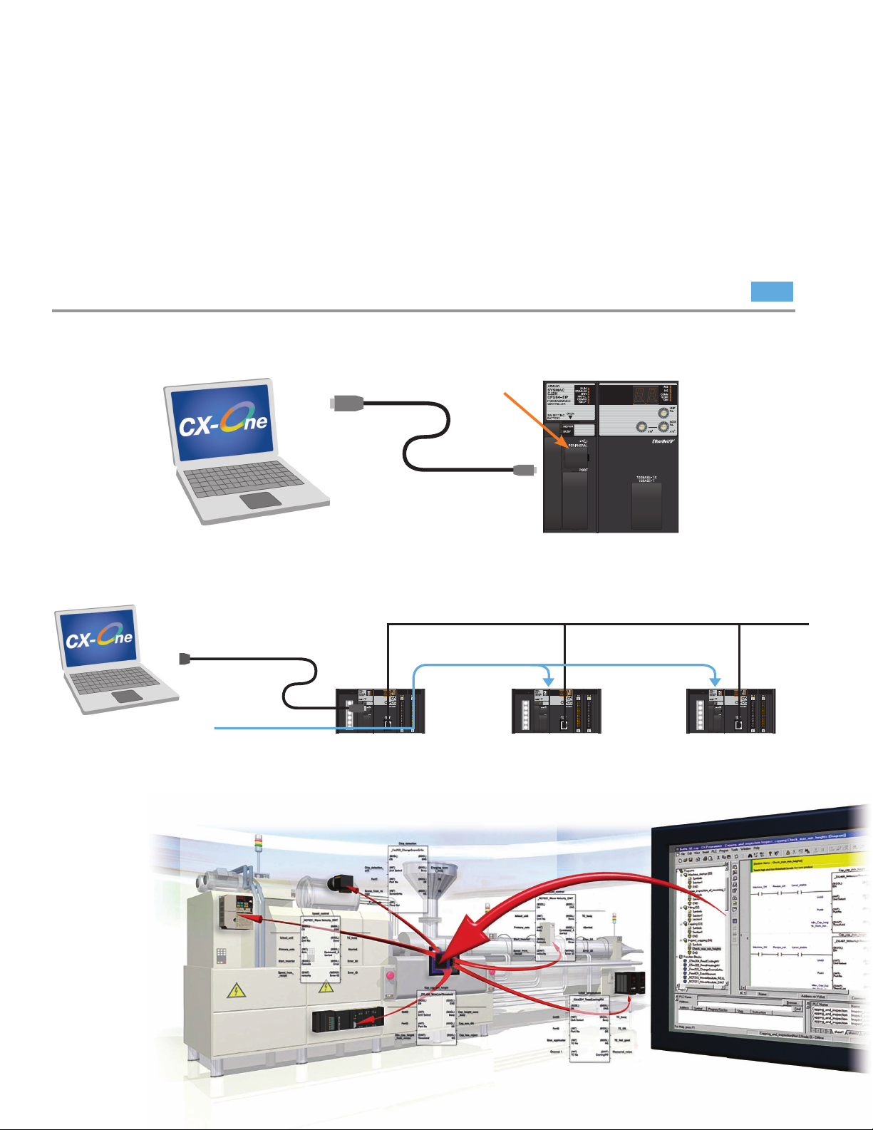
Connecting Support Software is Now
Easier and Safer.
Using General-purpose Networks for Support Software Interface. Connecting to a USB or EtherNet/IP port is
easy, by commercially available cable used around the world.
Easy Connection by USB
Commercially available cable can be connected to a USB port on the front panel of the CPU Unit.
» Simply Connect the Cable, with No Settings Required.
USB port (standard equipment)
Commercially available USB cable
CX-One (e.g., CX-Programmer)
» A CJ2 CPU Unit on an EtherNet/IP Network Can Be Accessed Via USB, with No Need for Routing Tables.
EtherNet/IP
USB
NEW
CX-One (e.g., CX-Programmer)
10
Page 11
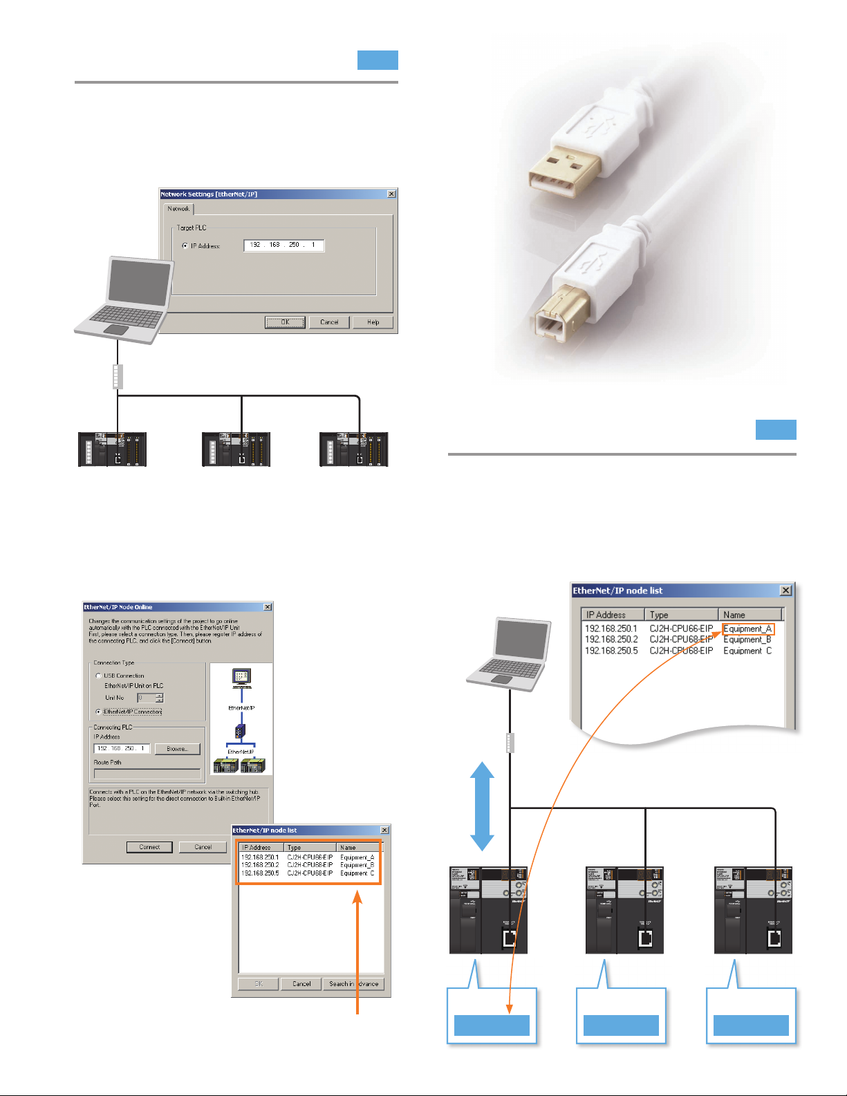
Easy Connection by EtherNet/IP
NEW
The built-in EtherNet/IP port enables smooth onsite remote debugging and maintenance.
» EtherNet/IP can be easily connected with
simply an IP address.
HUB
192.168.250.13 192.168.250.14 192.168.250.15
EtherNet/IP
» Even if the IP address is not known, it is easy
to connect by searching the PAC’s on the
EtherNet/IP network and selecting from a list.
Prevention of Erroneous Connection
by PAC Name Verifi cation
A user-set PAC name can be recorded in the CPU
Unit. When connecting online to a PAC, it can
be checked whether the project fi le matches the
name of the PAC that is to be connected, making
it possible to connect with confi dence to a PAC
installed in a location that cannot be seen.
CX-Programmer
HUB
Online connection
Erroneous connection is prevented
by checking whether the PAC name
matches when connecting online.
NEW
The PAC name can be easily found by
selecting from the list that is displayed.
PAC name
Equipment_A
PAC name
Equipment_B
PAC name
Equipment_C
11
Page 12
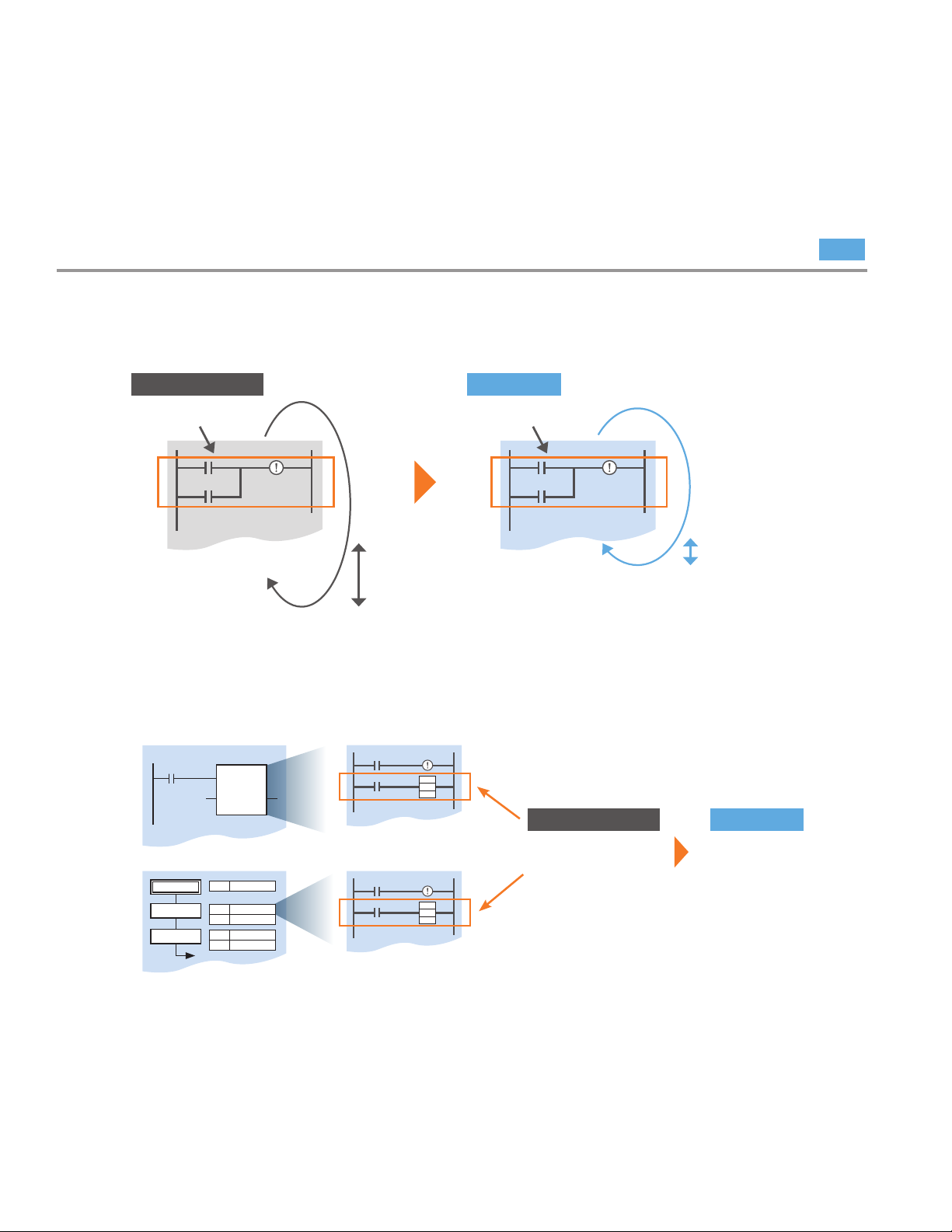
Easier On-site Debugging
Superior debugging functions reduce the time required for debugging and shorten the total lead time for
system startup and trouble countermeasures.
Stress-free Online Debugging
Effects on machinery operation are reduced.
» The additional cycle time due to Online editing has been reduced to approx. 1 ms
The previous additional cycle time of 8 ms has been shortened to 1 ms.
Previously (CJ1) CJ2
Online editing
CJ1 CPU
Additional time:
Approx.
8 ms
» Unlimited FB and SFC Online Editing
Function blocks and sequential function charts can be edited online with no limitation on program size.
Online editing
CJ2 CPU
Additional time:
Approx.
1 ms
NEW
FB
SFC
FB
FB defi nition
SFC program
Previously (CJ1) CJ2
The size of programs
that could be edited
online was limited to
4 Ksteps.
No limit
12
Page 13

Greatly Improved Debugging Effi ciency
Through Superior Data Tracing
High-speed, High-capacity Data Tracing is
now possible.
High-capacity Data Tracing
Times
More capacity
NEW
8
32 Kwords of data can be traced, and the EM
Area can also be used as trace memory.
Ample Sampling Data type and
Trigger Conditions
NEW
One, two, or four words of data and comparison
conditions can be specifi ed. For example, a
trigger can be set for when double-precision
data is larger than a specifi ed value.
Continuous Data Tracing
NEW
Sampled data in the trace memory of the
CPU Unit can be regularly collected at the
personal computer to enable sampling for
long periods or time. CSV fi les can be saved
at the personal computer.
Data collection
EtherNet/IP
CX-One Data Trace is also Upgraded
Ver.Up
The improved CJ2 trace function is fully utilized.
» A function has been added for superimposing
trace waveforms
» Trace results can be printed or saved as bit maps.
» The measurement times for two selected points can
be checked.
CJ2 CPU Unit
nd
time
2
1st time
Data is collected at the personal
computer at the specifi ed times.
When data that was sampled at high speed in the
PAC’s trace memory is saved at the personal computer,
the trace memory is cleared.
rd
time
3
13
Page 14

D100.05
15
D100
Bit
14 13 12 11 10 9876543210
E0_100.03
D200.00D100.05
W0.00
TIM
100-ms timer (BCD)
100-ms timer (binary)
Timer number
Timer number
Set value
Set value
0001
#10
W0.01
TIMX(550)
0002
#01FF
The BCD TIM and binary TIMX instructions can be used together.
D100 [W100]
Offset n (number of words)
Starting word address
Starting word address: D100
Offset +n
CH 15 0
Array Variable: ABC
Example
Ladder language:
Copy ABC[3] to D200
ST language:
Substitute ABC[0] to ABC[3].
0
1
2
3
4
5
6
7
8
9
WORD data
WORD data
WORD data
WORD data
WORD data
WORD data
WORD data
WORD data
WORD data
WORD data
MOV
ABC[3]
D200
5.00
To access
this data,
specify ABC
[3].
More Flexible Programming
The Greatest Program Diversity in the industry. A programming environment has been created that is highly
readable and can flexibly support changes in specifications, to enable efficient design and program entry
with few mistakes.
Highly Readable Programming
Programs are easy to see and easy to understand.
Bit Addresses can be used in the DM Area and EM Area.
NEW
DM and EM Area bits could not be specified with the previous
SYSMAC PLCs, but they can with the CJ2 CPU Units.
Examples
D100.05: Bit 05 of D100
E0_100.05: Bit 03 of E0_100
BCD and Binary Timer Instructions can be used Together.
NEW
With the CJ1 CPU Units, it was necessary to select in the initial setup of the CPU Unit whether BCD or binary
was to be used as the data format for timer instructions. With the CJ2 CPU Units, BCD or binary can be
selected individually for each instruction by setting the data format of the timer set value.
Address Offsets can be Specified
NEW
An offset can be specified in brackets after a starting
address to offset the starting address. If an address
in I/O memory is specified as the offset, the final
address can be dynamically specified according to
the contents of the specified memory address.
Example
D100[W100]: D100 is the starting address and the contents of W100
is the offset. If W100 is &5, then D105 is specified.
Array Variables make Data Specification Easier to Understand.
By using array variables, any data in a string of
data can be expressed using a subscript, making
programming easy to understand. Array variables
can also be used for data stacks and function block
I/O variables. Because they can be set for network
symbols, the exchange of multiple data items
14
with external devices can be easily programmed.
(Usable languages: Ladder, ST, SFC).
Page 15

data [i]
Symbol that indirectly specifies
the element number
Array variable name
Start of array
Value of element number i
(example when i = 5)
0
1
2
3
4
5
data[0]
data[1]
data[2]
data[3]
data[4]
data[5]
Element number
A Symbol Can be used for an Array
Variable Subscript.
NEW
A physical address or symbol can be specifi ed
for an array subscript, so data can be
dynamically specifi ed.
Example Data[i]: An element number is indirectly specifi ed by the
value of symbol i. If the value of symbol i is &5, data[5] is specifi ed
for element number 5.
Memory Attributes in the Ladder Editor
can be Understood at a Glance.
Tag (network symbols) memory attributes can
be understood at a glance in the Ladder Editor
Window, enabling an easily understandable
program to be created.
Ver.Up
Example
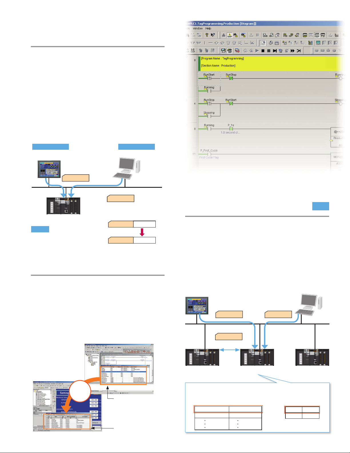
New Instructions are Supported.
:Published :Input :Output
Operation start Operation stop
Operation status
NEW
New instructions such as tracking, sorting, and
fl oating-point decimal maximum/minimum value
search instructions are supported.
The Number of Communications Logic
Ports has Increased to 64.
Programming can be performed with no need to
pay attention to the number of logic ports.
NEW
Up to 128 Cyclic Tasks
4
Times
are Supported.
More than before
NEW
The user program can be divided into up to 128
tasks. Using smaller task programs makes it easier
to structure programs. This also contributes to shorter
cycle times by controlling the tasks that are being
executed or not executed in smaller units.
Languages Conforming to IEC Are Supported.
Ladder diagrams and ST languages can be freely
combined and made into components as function
blocks (FBs), allowing programs to be created in the
optimum language for the particular process.
User program
Task
Task
Task
Task
a:=a+1;
RESULTS=0.0;
IF M = TRUE THEN
RESULTS = SIN(data):
ENDIF;
Ladder diagram
Control of equipment and
external devices
FBs
FB
Modularization
and reusability
ST
Math and character string
processing
Programming Structuring and Reusability.
Highly Independent Programs Can Be
Easily Created.
SFC
Step progression control
The programming language suited to the process can be used.
15
Page 16

CPU Rack
End Cover
CJ1W-TER01
(One End Cover is provided as a standard
accessory with the CPU Unit.)
Power Supply Unit
CJ1W-P@@@ (@)
CPU Unit
CJ2H-CPU@@-EIP
I/O Control Unit
CJ1W-IC101
(Required only when connecting
to an Expansion Rack.)
CJ-series Basic I/O Units
CJ-series Special I/O Units
CJ-series CPU Bus Units
Total: 10 Units max
System Configuration
CJ-series CPU Racks ■
A CJ-series CPU Rack consists of a CPU Unit, Power Supply Unit, Configuration Units (Basic I/O Units, Special I/O Units, and CPU
Bus Units), and an End Cover.
Required Units ●
Rack Unit name Required number of Units
Power Supply Unit
CPU Unit
CPU Rack
I/O Control Unit
Number of Configuration Units
End Cover
Types of Units ●
In the SYSMAC CJ Series, Units are classified into the following three types. The number of Racks differs depending on the type.
Type Appearance (example) Description Unit recognition method No. of units
Basic I/O Units
Units with contact inputs and contact outputs. Recognized by the CPU Unit according
1
1
Required only for mounting to an Expansion Rack.
10 max. (Same for all models of CPU Unit.)
(The number of Basic I/O Units, Special I/O Units, and CPU Bus Units can be varied. The number does
not include the I/O Control Unit.)
1 (Included with CPU Unit.)
No restrictions.
to the position of the Rack and slot.
16
Special I/O
Units
CPU Bus Units
Special I/O Units provide more advanced functions
than do Basic I/O Units, including I/O other than
contact inputs and contact outputs.
Examples of Special I/O Units are Analog I/O Units
and High-speed Counter Units. They differ from
CPU Bus Units (including Network Communications
Units) in having a smaller area for exchanging data
with the CPU Unit.
CPU Bus Units exchange data with the CPU Unit
via the CPU Bus.
Examples of CPU Bus Units are Network
Communications Units and Serial Communications
Units. They differ from Special I/O Units in having a
larger area for exchanging data with the CPU Unit.
Recognized by the CPU Unit according
to the unit number (0 to 95) set with the
rotary switches on the front panel.
Recognized by the CPU Unit according
to the unit number (0 to F) set with the
rotary switch on the front panel.
A maximum of 96 Units can
be connected. (Multiple unit
numbers are allocated per Unit,
depending on the model and
settings.)
A maximum of 15 Units can be
mounted. (The built-in EtherNet/
IP port on the CPU Unit must
be counted as one of the CPU
Bus Units.)
Page 17

System Configuration
Configuration Units: 10 max.
Power Supply Unit
CJ1W-P@@@(@)
CPU Unit
CJ2H-CPU@@-EIIP
I/O Control Unit
CJ1W-IC101
I/O Interface Unit
CJ1W-II101
Power Supply Unit
CJ1W-P@@@(@)
Power Supply Unit
CJ1W-P@@@(@)
Power Supply Unit
CJ1W-P@@@(@)
CPU Rack
Expansion
Rack
Expansion
Rack
Number of Expansion Racks:
Up to 3 Expansion Racks can be connected.
I/O Connecting Cable
CS1W-CN@@3
Configuration Units: 10 max.
I/O Interface Unit
CJ1W-II101
I/O Interface Unit
CJ1W-II101
I/O Connecting Cable
CS1W-CN@@3
I/O Connecting Cable
CS1W-CN@@3
Expansion
Rack
Total
cable
length
≤ 12 m
Configuration Units: 10 max.
Configuration Units: 10 max.
CJ-series Expansion Racks ■
A CJ-series Expansion Rack consists of a Power Supply Unit, an I/O Interface Unit, Configuration Units (Basic I/O Units, Special I/O
Units, and CPU Bus Units), and an End Cover.
Required Units ●
Rack Unit name Required number of Units
CPU Rack I/O Control Unit
Expansion
Rack
Note: 1. Mounting the I/O Control Unit in any other location may cause faulty operation.
2. Mounting the I/O Interface Unit in any other location may cause faulty operation.
Maximum Number of Configuration Units That Can Be Mounted ●
CPU Unit Model Total Units No. of Units on CPU Rack No. of Expansion Racks
CJ2H CJ2H-CPU68-EIP
Power Supply Unit
I/O Interface Unit
Number of Configuration Units
End Cover
CJ2H-CPU67-EIP
CJ2H-CPU66-EIP
CJ2H-CPU65-EIP
CJ2H-CPU64-EIP
One Unit. Required only when an Expansion Rack is used. Mount the I/O Control Unit immediately to the
right of the CPU Unit. (See note 1.)
One Unit
One Unit. Mount the I/O Interface Unit immediately to the right of the Power Supply Unit. (See note 2.)
Ten Units max. (The number of Basic I/O Units, Special I/O Units, and CPU Bus Units can be varied.
This number does not include the I/O Interface Unit.)
One (Included with the I/O Interface Unit.)
40 10 per Rack 3 Racks x 10 Units
17
Page 18

External Interface
A CJ2H CPU Unit provides three communications ports for external interfaces: a peripheral (USB) port, a serial port and an EtherNet/IP port.
Battery Compartment
LED Indicators
DIP Switch
(inside the battery compartment)
Memory Card Indicators
Indicates the Memory Card status
(access and power supply).
Peripheral (USB) Port
Connected to Programming Devices,
such as the CX-Programmer
Serial Port
Connected to Programming Devices, Host
Computers, general-purpose external devices,
Programmable Terminals, and other devices.
EtherNet/IP Port
Connected to the information management
system such as Host Computer
Simple Backup/Memory Card
Power Supply Switch
Used to back up Memory
Card data or turn OFF the
power when removing the
Memory Card.
Memory Card Connector
Connects the Memory Card
to the CPU Unit.
Memory Card Eject Button
Press the eject button to
remove the Memory Card
from the CPU Unit.
External Interface
18
Page 19
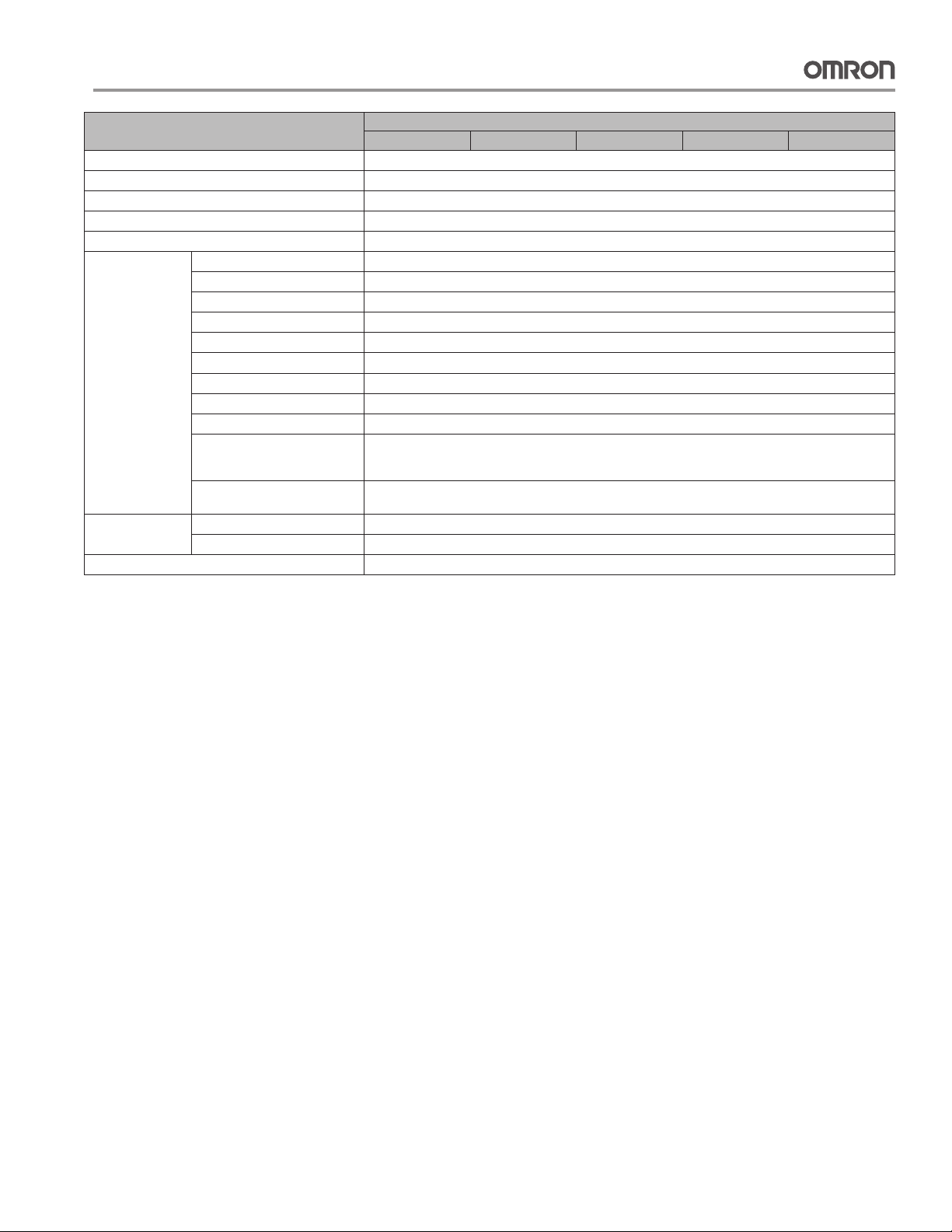
General Specifications
Item
Enclosure Mounted in a panel
Grounding Less than 100 Ω
CPU Rack Dimensions 90 mm × 65 mm × 80 mm (W × H × D)
Weight 280 g or less
Current Consumption 5 VDC, 0.82 A
Use
Environment
Battery Life 5 years at 25°C
Applicable Standards Conforms to cULus and EC Directives.
Ambient Operating Temperature 0 to 55°C
Ambient Operating Humidity 10% to 90%
Atmosphere Must be free from corrosive gases.
Ambient Storage Temperature −20 to 70°C (excluding battery)
Altitude 2,000 m or less
Pollution Degree 2 or less: Conforms to JIS B3502 and IEC 61131-2.
Noise Immunity 2 kV on power supply line (Conforms to IEC 61000-4-4.)
Overvoltage Category Category II: Conforms to JIS B3502 and IEC 61131-2.
EMC Immunity Level Zone B
Vibration Resistance Conforms to JIS C60068-2-6.
Shock Resistance Conforms to JIS C60068-2-27.
Model CJ1W-BAT01
CPU64-EIP CPU65-EIP CPU66-EIP CPU67-EIP CPU68-EIP
5 to 8.4 Hz with 3.5-mm amplitude, 8.4 to 150 Hz
Acceleration of 9.8 m/s
2
, 3 times in X, Y, and Z directions (100 m/s2 for Relay Output Units)
147 m/s
2
for 100 min in X, Y, and Z directions (10 sweeps of 10 min each = 100 min total)
CJ2H-
19
Page 20

Performance Specifications
Item
User Memory 50K steps 100K steps 150K steps 250K steps 400K steps
I/O Bits 2,560 bits
Processing Speed Overhead Processing Time Normal Mode: 200 μs
Execution Time Basic Instructions: 0.016 μs min.;
Interrupt Task Start Time 30 μs
Maximum Number of Connectable Units Total per CPU Rack or Expansion Rack: 10 Units max.;
Maximum Number of Expansion Racks 3 max.
CIO Area I/O Area 2,560 bits (160 words): Words CIO 0000 to CIO 0159
Link Area 3,200 bits (200 words): Words CIO 1000 to CIO 1199
CPU Bus Unit Area 6,400 bits (400 words): Words CIO 1500 to CIO 1899
Special I/O Unit Area 15,360 bits (960 words): Words CIO 2000 to CIO 2959
DeviceNet Area 9,600 bits (600 words): Words CIO 3200 to CIO 3799
Internal I/O Area 3,200 bits (200 words): Words CIO 1300 to CIO 1499
Work Area 8,192 bits (512 words): Words W000 to W511
Holding Area 8,192 bits (512 words): Words H000 to H511
Auxiliary Area Read-only: 31,744 bits (1,984 words)
Temporary Area 16 bits: TR0 to TR15
Timer Area 4,096 timer numbers (T0000 to T4095 (separate from counters))
Counter Area 4,096 counter numbers (C0000 to C4095 (separate from timers))
DM Area 32k words (Bits in the DM Area can be addressed either by bit or by word.)
EM Area 32k words/bank × 25 banks max.: E00_00000 to E18_32767 max.
Force-set/reset Enabled
Banks
Index Registers IR0 to IR15
Cyclic Task Flag Area 128 flags
Memory Card 128 MB, 256 MB, or 512 MB
Operating Modes PROGRAM Mode: Programs are not executed. Preparations can be executed prior to program execution in this
Execution Mode Normal Mode
CPU64-EIP CPU65-EIP CPU66-EIP CPU67-EIP CPU68-EIP
(If tag data links are used with EtherNet/IP, add the following to the above time: 100 μs + Number of
transferred words × 0.33 μs)
Special Instructions: 0.048 μs min.
Total per PAC: 40 Units max.
37,504 bits (2,344 words): Words CIO 3800 to CIO 6143
Cannot be used for external I/O.
Cannot be used for external I/O.
Bits in this area maintain their ON/OFF status when PAC is turned OFF or operating mode is changed.
Words H512 to H1535: These words can be used only for function blocks. They can be used only for
function block instances (i.e., they are allocated only for internal variables in function blocks).
• 7,168 bits (448 words): Words A0 to A447
• 24,576 bits (1,536 words): Words A10000 to A11535
Read/write: 16,384 bits (1,024 words) in words A448 to A1471
DM Area words for Special I/O Units: D20000 to D29599 (100 words × 96 Units)
DM Area words for CPU Bus Units: D30000 to D31599 (100 words × 16 Units)
(Bits in the EM Area can be addressed either by bit or by word.)
32K words × 4
banks
EM3 EM3 EM6 to EM9 EM7 to EME EM11 to EM18
Force-setting/resetting is enabled only for areas specified for automatic address allocation.
These are special registers for storing PAC memory addresses for indirect addressing. (Index
Registers can be set so that they are unique in each task or so that they are shared by all tasks.)
MONITOR Mode: Programs are executed, and some operations, such as online editing, and changes to present
RUN Mode: Programs are executed. This is the normal operating mode.
32K words × 4
banks
mode.
values in I/O memory, are enabled in this mode.
CJ2H-
32K words × 10
banks
32K words × 15
banks
32K words × 25
banks
20
Page 21

Performance Specifications
Item
Programming Languages Ladder Logic (LD),
Function Blocks Maximum number of definitions 2,048
Maximum number of instances 2,048
Tasks Type of Tasks Cyclic tasks
Number of Tasks Cyclic tasks: 128
Symbols
(Variables)
Data Tracing Memory Capacity 8,000 words 16,000 words 32,000 words
File Memory Memory Card (128, 256, or 512 Mbytes) (Use the Memory Cards provided by OMRON.)
Source/Comment
Memory
Type of Symbols • Local symbols: Can be used only within a single task in the PAC.
Data Type of Symbols • BOOL (bit)
Maximum Size of Symbol 32k words
Array Symbols (Array Variables) One-dimensional arrays
Number of Array Elements 32,000 elements max.
Number of Registrable Network
Symbols (Tags)
Length of Network Symbol (Tag)
Name
Encoding of Network Symbols
(Tags)
Number of Samplings Bits = 31, one-word data =16, two-word data = 8, four-word data = 4
Sampling Cycle 1 to 2,550 ms (Unit: 1 ms)
Trigger Conditions ON/OFF of specified bit
Delay Value −32,768 to +32,767 ms
Function block program memory,
comment file, program index file,
symbol tables
CPU64-EIP CPU65-EIP CPU66-EIP CPU67-EIP CPU68-EIP
Sequential Function Charts (SFC),
Structured Text (ST), and
Instruction Lists (IL)
Interrupt tasks (Power OFF interrupt tasks, scheduled interrupt tasks, I/O interrupt tasks, and
external interrupt tasks)
Interrupt tasks: 256
(Interrupt tasks can be defined as cyclic tasks to create extra cyclic tasks. Therefore, the total
number of cyclic tasks is actually 384 max.)
• Global symbols: Can be used in all tasks in the PAC.
• Network symbols (tags): I/O memory in the CPU Unit can be externally accessed using symbols, depending on
parameter settings.
• UINT (one-word unsigned binary)
• UDINT (two-word unsigned binary)
• ULINT (four-word unsigned binary)
• UINT BCD (one-word unsigned BCD)
• INT (one-word signed binary)
• DINT (two-word signed binary)
• LINT (four-word signed binary)
• UDINT BCD (two-word unsigned BCD)
• ULINT BCD (four-word unsigned BCD)
• REAL (two-word oating-point)
• LREAL (four-word oating-point)
• CHANNEL (word)
• NUMBER (constant or number)
• WORD (one-word hexadecimal)
• DWORD (two-word hexadecimal)
• LWORD (four-word hexadecimal)
• TIMER
• COUNTER
20,000 max.
255 bytes max.
UTF-8
(Up to 32k words x 25 banks when EM is specified in CX-Programmer)
Data comparison of specified word
Data size: 1 word, 2 words, 4 words
Comparison Method: Equals (=), Greater Than (>), Greater Than or Equals (≥), Less Than (<), Less Than or Equals
(≤), Not Equal (≠)
EM file memory (Part of the EM Area can be converted for use as file memory.)
Capacity: 3.5 Mbytes
CJ2H-
21
Page 22

Performance Specifications
Item
Logical Ports for
Communications
Cip
Communications
Specification
Peripheral (USB) Port USB 2.0-compliant B-type connector
Baud Rate 12 Mbps max.
Transmission Distance 5 m max.
Serial Port Interface: Conforms to EIA RS-232C.
Communications Method Half-duplex
Synchronization Method Start-stop
Baud Rate 0.3, 0.6, 1.2, 2.4, 4.8, 9.6, 19.2, 38.4, 57.6, or 115.2 (kbps)
Transmission Distance 15 m max.
EtherNet/IP Port —
Media Access Method CSMA/CD
Modulation Baseband
Transmission Paths Star
Baud Rate 100 Mbps (100Base-TX)
Transmission Media Shielded twisted-pair (STP) cable; Categories: 5, 5e
Transmission Distance 100 m (between hub and node)
Number of Cascade Connections No restrictions if switching hub is used.
Transmission Specifications
CIP Communications: Tag Data Links —
Communications
Communication Specifications
CIP Communications: Explicit Messages —
FINS Communications —
EtherNet/IP Conformance Test Conforms to A5.
EtherNet/IP Interface 10Base-T/100Base-TX
Note 1. “Packets per second” is the number of communications packets that can be processed per second.
2. Large Forward Open (CIP optional specification) must be supported in order for 505 to 1,444 bytes to be used as the data size. Application is supported between CS/CJ-series PLCs.
When connecting to devices from other manufacturers, make sure that the devices support the Large Forward Open specification.
3. If the maximum number is exceeded, refreshing will require more than one CPU Unit cycle.
4. When changing parameters, however, the EtherNet/IP port where the change is made will be restarted. In addition, a timeout will temporarily occur at the other node that was
communicating with that port, and it will then recover automatically.
5. The EtherNet/IP port supports an IGMP client, so unnecessary multicast packets are filtered by using a switching hub that supports IGMP snooping.
Logical Ports 8 ports (Used for SEND, RECV, CMND, PMCR, TXDU, and RXDU instructions.)
Extended Logical Ports 64 ports (Used for SEND2, RECV2, CMND2, and PMCR2 instructions.)
Class 3
(Number of Connections)
UCMM
(Non-connection Type)
Number of Connections 256
Packet Interval (Refresh period) 0.5 to 10,000 ms (Unit: 0.5 ms)
Permissible Communications Band 6,000 pps (See note 1.)
Number of Tag Sets 256
Type of Tags CIO, DM, EM, HR, and WR
Number of Tags per Connection 8 (Seven tags if PAC status is included in the segment.)
Maximum Link Data Size per Node 184,832 words
Maximum Data Size per Connection 252 or 722 words (See note 2.)
Number of Registrable Tag Set 256 (1 connection = 1 segment)
Maximum Tag Set Size 722 words (One word is used when PAC status is included in the segment.)
Maximum Number of Tags Refreshable in
a Single Cycle of CPU Unit (See note 3.)
Data Size Refreshable in a Single Cycle
of CPU Unit (See note 3.)
Change of Tag Data Link Parameter
Settings during Operation
Multi-cast Packet Filter (See note 5.) OK
Class 3 (Number of Connections) Number of connections: 128
UCMM (Non-connection Type) Maximum number of clients that can communicate at the same time: 32
CIP Routing OK (CIP routing is enabled for the following remote Units: CJ1W-EIP21 and CJ2H-CPU6
FINS/UDP OK
FINS/TCP 16 connections max.
CPU64-EIP CPU65-EIP CPU66-EIP CPU67-EIP CPU68-EIP
Number of connections: 64
Maximum number of clients that can communicate at the same time: 32
Maximum number of servers that can communicate at the same time: 40
Can be set for each connection. (Data will be refreshed at the set interval, regardless of the number of nodes.)
(Data is synchronized within each connection.)
Output/send (CPU Unit to EtherNet/IP): 256
Input/receive (EtherNet/IP to CPU Unit): 256
Output/send (CPU to EtherNet/IP): 6,432 words
Input/receive (EtherNet/IP to CPU): 6,432 words
OK (See note 4.)
Maximum number of servers that can communicate at the same time: 32
Auto Negotiation/Fixed Setting
CJ2H-
-EIP.)
22
Page 23

Performance Specifications
International Standards
• The standards indicated in the “Standards” column are
those current for UL, CSA, cULus, cUL, NK, and Lloyd
standards and EC Directives as of the end of May 2008.
The standards are abbreviated as follows: U: UL, U1: UL
Class I Division 2 Products for Hazardous Locations, C:
CSA, UC: cULus, UC1: cULus Class I Division 2 Products
for Hazardous Locations, CU: cUL, N: NK, L: Lloyd, and CE:
EC Directives.
• Ask your OMRON representative for the conditions under
which the standards were met.
● EC Directives
The EC Directives applicable to PAC’s, PLC’s include the
EMC Directives and the Low Voltage Directive. OMRON
complies with these directives as described below.
● EMC Directives Applicable Standards
EMI: EN61000-6-4, EN61131-2
EMS: EN61000-6-2, EN61131-2
PAC’s, PLC’s are electrical devices that are incorporated
in machines and manufacturing installations. OMRON
PAC’s, PLC’s conform to the related EMC standards so
that the devices and machines into which they are built
can more easily conform to EMC standards. The actual
PAC’s, PLC’s have been checked for conformity to EMC
standards. Whether these standards are satisfied for
the actual system, however, must be checked by the
customer.
EMC-related performance will vary depending on the
configuration, wiring, and other conditions of the equipment
or control panel in which the PAC, PLC is installed. The
customer must, therefore, perform final checks to confirm
that the overall machine or device conforms to
EMC standards.
● Low Voltage Directive
Applicable Standard:EN61131-2
VDC must satisfy the appropriate safety requirements.
With PAC’s, PLC’s, this applies to Power Supply Units and
I/O Units that operate in these voltage ranges.
These Units have been designed to conform to
EN61131-2, which is the applicable standard for PAC’s
and PLC’s.
23
Page 24
Ordering Information
Basic Configuration Units
CPU Units
CJ2 CPU Units ■
Specifications
Product
name
CJ2 CPU Units
Note: Add 0.15 A per Adapter when using NT-AL001 RS-232C/RS-222A Adapters.
Add 0.04 A per Adapter when using CJ1W-CIF11 RS-422A Adapters.
The following accessories are included with the CPU Unit.
Battery
End Cover
End Plate
I/O capacity/
Mountable Units
(Expansion
Program
capacity
Data memory
capacity
Racks)
832K words
(DM: 32K words, EM:
32K words × 25 banks)
512K words
(DM: 32K words, EM:
32K words × 15 banks)
352K words
(DM: 32K words, EM:
32K words × 10 banks)
160K words
(DM: 32K words, EM:
32K words × 4 bank)
160K words
(DM: 32K words, EM:
32K words × 4 bank)
2,560 points/
40 Units
(3 Expansion
Racks max.)
400K steps
250K steps
150K steps
100K steps
50K steps
Item Specifications
CJ1W-BAT01
CJ1W-TER01(The End Cover must be connected to the right end of the CPU Rack.)
PFP-M(2 stoppers)
Function block
program,
comment, symbol
memory
3.5MB
Current
consumption (A)
5 V 24 V
0.82
(See
note.)
—
Model Standards
CJ2H-CPU68H-EIP
CJ2H-CPU67H-EIP
CJ2H-CPU66H-EIP
CJ2H-CPU65H-EIP
CJ2H-CPU64H-EIP
UC1, N, L,
CE
Power Supply Units ■
One Power Supply Unit is required for each Rack.
Output capacity Options
24-VDC
output
capacity
Product name
AC
Power
Supply
Unit
DC
Power
Supply
Unit
Power
supply
voltage
100 to 240
VAC
24 VDC
5-VDC
output
capacity
5 A 0.8 A 25 W
2.8 A 0.4 A 14 W No No CJ1W-PA202
5A 0.8 A 25 W No No CJ1W-PD025
2 A 0.4 A 19.6 W No No CJ1W-PD022
Total power
consumption
24-VDC
service power
supply
No
RUN
output
Maintenance
forecast
monitor
No Yes CJ1W-PA205C
Yes No CJ1W-PA205R
Model Standards
UC1, N, L,
CE
UC1, CE
24
Page 25
Ordering Information
Expansion Racks
Select the I/O Control Unit, I/O Interface Unit, Expansion Connecting Cable, and CJ-series Power Supply Unit.
CJ-series I/O Control Unit (Mounted on CPU Rack when Connecting Expansion Racks) ■
Current
Product name Specifications
CJ-series I/O
Control Unit
Note: Mounting the I/O Control Unit in any other location may cause faulty operation.
Mount one I/O Control Unit on the CJ-series CPU Rack when connecting one
or more CJ-series Expansion Racks.
Connecting Cable: CS1W-CN
Connected Unit: CJ1W-II101 I/O Interface Unit
Mount to the right of the CPU Unit.
3 Expansion Connecting Cable
CJ-series I/O Interface Unit (Mounted on Expansion Rack) ■
Product name Specifications
CJ-series I/O
Interface Unit
One I/O Interface Unit is required on each Expansion Rack.
Connecting Cable: CS1W-CN
Mount to the right of the CPU Unit.
3 Expansion Connecting Cable
consumption (A)
5 V 24 V
0.02 — CJ1W-IC101
Current
consumption (A)
5 V 24 V
0.13 — CJ1W-II101
Model Standards
Model Standards
UC1, N, L,
CE
UC1, N, L,
CE
Note: Mounting the I/O Interface Unit in any other location may cause faulty operation.
I/O Connecting Cables ■
Product name Specifications Model Standards
Cable length: 0.3 m CS1W-CN313
I/O Connecting
Cable
• Connects an I/O Control Unit on CJ-series CPU Rack to an I/O Interface Unit on a
CJ-series Expansion Rack.
or
• Connects an I/O Interface Unit on CJ-series Expansion Rack to an I/O Interface Unit on
another CJ-series Expansion Rack.
Cable length: 0.7 m CS1W-CN713
Cable length: 2 m CS1W-CN223
Cable length: 3 m CS1W-CN323
Cable length: 5 m CS1W-CN523
Cable length: 10 m CS1W-CN133
Cable length: 12 m CS1W-CN133-B2
N, L, CE
25
Page 26

Ordering Information
Programming Devices
Support Software ■
Product name Specifications Model Standards
The CX-One is a comprehensive software package that integrates Support Software
FA Integrated Tool
Package CX-One
Ver. 3.
Note: If the complete CX-One package is installed, approximately 2.5 GB of Hard disk space will be required.
for OMRON PAC’s , PLC’s and components.
CX-One runs on the following OS.
Windows 2000 (Service Pack 3 or higher), XP, or Vista
CX-One Version 3.
For details, refer to the CX-One catalog (Cat. No. R134).
includes CX-Programmer Ver.8. and CXSimulator Ver. 1. .
Number of
licenses
1 license
3 licenses CXONE-AL03C-V3
10 licenses CXONE-AL10C-V3
30 licenses CXONE-AL30C-V3
50 licenses CXONE-AL50C-V3
Media
CXONE-AL01C-V3
CD
—
Programming Device Connecting Cable
Peripheral (USB) Port ■
Use commercially available USB cable.
Specifications: USB 1.1 or 2.0 cable (A connector - B connector), 5.0 m max.
EtherNet/IP Port ■
Support Software can also be connected via the built-in EtherNet/IP port. Use commercially available 100Base-TX twisted-pair cable
with the same specifications as for an EtherNet/IP Unit.
Specifications: Twisted-pair cable with RJ45 modular connectors at both ends. Connect between EtherNet/IP Unit or built-in EtherNet/
IP port and switching hub. Use STP (shielded twisted-pair) cable of category 5 or 5e.
Optional Products and Maintenance Products
Product name Specifications Model Standards
Memory Cards
Flash memory, 128 MB HMC-EF183
N, L, CE Flash memory, 256 MB HMC-EF283
Flash memory, 512 MB HMC-EF583
Memory Card Adapter (for computer PCMCIA slot) HMC-AP001 CE
Product name Specifications Model Standards
Battery Set
End Cover
Battery for CJ2H-CPU -EIP and CJ1M-CPU
CPU Unit maintenance
Mounted to the right-hand side of CJ-series CPU
Racks or Expansion Racks.
Note 1. The battery is included as a standard
accessory with the CPU Unit.
2. The battery service life is 5 years at 25°C.
(The service life depends on the ambient
operating temperature and the power
conditions.)
3. Use batteries within two years of
manufacture.
One End Cover is provided as a standard accessory
with each CPU Unit and I/O Interface Unit.
CJ1W-BAT01 CE
CJ1W-TER01 UC1, N, L, CE
26
Page 27

Ordering Information
Basic I/O Units
Input Units ■
Product
Unit
name
classification
I/O
points
Input voltage
and current
Specifications
Commons
Additional
functions
External
connection
No. of
words
allocated
Current
consumption
(A)
5 V 24 V
Model Standards
DC Input
Units
CJ
Basic
I/O
Units
AC Input
Units
Note: Connectors are not provided with these connector models. Either purchase one of the following 40-pin Connectors,
or use an OMRON XW2
8 inputs
16 inputs 24 VDC, 7 mA
32 inputs 24 VDC, 4.1 mA
32 inputs 24 VDC, 4.1 mA
64 inputs 24 VDC, 4.1 mA
64 inputs 24 VDC, 4.1 mA
16 inputs
8 inputs
12 to 24 VDC,
10 mA
100 to 120 VAC,
7 mA (100 V,
50 Hz)
200 to 24 VAC,
10 mA (200 V,
50 Hz)
Connector-Terminal Block Conversion Unit or a G7 I/O Relay Terminal.
Independent
contacts
16 points,
1 common
16 points,
1 common
16 points,
1 common
16 points,
1 common
16 points,
1 common
16 points,
1 common
8 points,
1 common
Removable
terminal block
Removable
terminal block
Fujitsu
connector
MIL connector 2 words 0.09 —
—
Fujitsu
connector
MIL connector 4 words 0.09 —
Removable
terminal block
Removable
terminal block
1 word 0.09 — CJ1W-ID201
1 word 0.08 — CJ1W-ID211
2 words 0.09 —
4 words 0.09 —
1 word 0.09 — CJ1W-IA111
1 word 0.08 — CJ1W-IA201
CJ1W-ID231
(See note.)
CJ1W-ID232
(See note.)
CJ1W-ID261
(See note.)
CJ1W-ID262
(See note.)
UC1, N, L, CE
27
Page 28

Ordering Information
Output Units ■
Product
Unit
name
classification
Relay
Contact
Output
Units
I/O
points
8
outputs
250 VAC/
24 VDC, 2 A
Maximum
switching
capacity
Specifications
Commons
Independent
contacts
Additional
functions
External
connection
Removable
terminal block
No. of
consumption
words
allocated
1 word 0.09
5 V 24 V
Current
(A)
0.048
max.
Model Standards
CJ1W-OC201
CJ
Basic
I/O
Units
Transistor
Output
Units
Triac
Output
Unit
16
outputs
8
outputs
8
outputs
8
outputs
8
outputs
16
outputs
16
outputs
32
outputs
32
outputs
32
outputs
64
outputs
64
outputs
64
outputs
8
outputs
250 VAC/
24 VDC, 2 A
12 to 24 VDC,
2 A, sinking
24 VDC, 2 A,
sourcing
12 to 24 VDC,
0.5 A, sinking
24 VDC, 0.5 A,
sourcing
12 to 24 VDC,
0.5 A, sinking
24 VDC, 0.5 A,
12 to 24 VDC,
0.5 A, sinking
12 to 24 VDC,
0.5 A, sourcing
12 to 24 VDC,
0.5 A, sinking
12 to 24 VDC,
0.3 A, sinking
12 to 24 VDC,
0.3 A, sourcing
12 to 24 VDC,
0.3 A, sinking
250 VAC, 0.6 A
16 points,
1 common
4 points,
1 common
4 points,
1 common
8 points,
1 common
8 points,
1 common
16 points,
1 common
16 points,
1 common
16 points,
1 common
16 points,
1 common
16 points,
1 common
16 points,
1 common
16 points,
1 common
16 points,
1 common
8 points,
1 common
—
Short-circuit
protection,
disconnection
detection
—
Short-circuit
protection
—
Short-circuit
protection
—
Short-circuit
protection
— MIL connector 2 words 0.14 —
—
— MIL connector 4 words 0.17 —
— MIL connector 4 words 0.17 —
—
Removable
terminal block
Removable
terminal block
Removable
terminal block
Removable
terminal block
Removable
terminal block
Removable
terminal block
Removable
terminal block
Fujitsu
connector
MIL connector 2 words 0.15 —
Fujitsu
connector
Removable
terminal block
1 word 0.11
1 word 0.09 — CJ1W-OD201
1 word 0.11 — CJ1W-OD202
1 word 0.10 — CJ1W-OD203
1 word 0.10 — CJ1W-OD204
1 word 0.10 — CJ1W-OD211
1 word 0.10 — CJ1W-OD212
2 words 0.14 —
4 words 0.17 —
1 word 0.22 — CJ1W-OA201
0.096
max.
CJ1W-OC211
UC1, N, L, CE
CJ1W-OD231
(See note.)
CJ1W-OD232
(See note.)
CJ1W-OD233
(See note.)
CJ1W-OD261
(See note.)
CJ1W-OD262
(See note.)
CJ1W-OD263
(See note.)
Note: Connectors are not provided with these connector models. Either purchase one of the following 40-pin Connectors,
or use an OMRON XW2
Connector-Terminal Block Conversion Unit or a G7 I/O Relay Terminal.
28
Page 29

Ordering Information
I/O Units ■
Unit
classification
CJ
Basic
I/O
Units
Product
name
points
DC Input/
Transistor
Output
Units
TTL I/O
Units
I/O
16
inputs
16
inputs
16
inputs
16
inputs
16
inputs
16
inputs
32
inputs
32
inputs
32
inputs
32
inputs
32
inputs
32
inputs
Input voltage,
Input current
Maximum
switching
24 VDC, 7 mA
250 VAC/24
VDC, 0.5 A,
sinking
24 VDC, 7 mA
24 VDC, 0.5 A,
sourcing
24 VDC, 7 mA
12 to 24 VDC,
0.5 A, sinking
24 VDC, 4.1 mA
12 to 24 VDC,
0.3 A, sinking
24 VDC, 4.1 mA
12 to 24 VDC,
0.3 A, sinking
5 VDC, 35 mA
5 VDC, 35 mA
capacity
Specifications
Commons
16 point,
1 common
16 point,
1 common
16 point,
1 common
16 point,
1 common
16 point,
1 common
16 point,
1 common
16 point,
1 common
16 point,
1 common
16 point,
1 common
16 point,
1 common
16 point,
1 common
16 point,
1 common
Additional
functions
—
—
—
Short-circuit
protection
—
—
—
—
—
—
—
—
External
connection
Fujitsu
connector
MIL
connector
MIL
connector
Fujitsu
connector
MIL
connector
MIL
connector
Current
consumption
No. of
(A)
words
allocated
2 words 0.13 —
2 words 0.13 —
2 words 0.13 —
4 words 0.14 —
4 words 0.14 —
4 words 0.19 —
5 V 24 V
Model Standards
CJ1W-MD231
(See note 2.)
CJ1W-MD232
(See note 2.)
CJ1W-MD233
(See note 2.)
CJ1W-MD261
(See note 1.)
CJ1W-MD263
(See note 1.)
CJ1W-MD563
(See note 1.)
UC1, N, CE
UC1, N, L, CE
UC1, N, CE
Note 1. Connectors are not provided with these connector models. Either purchase one of the following 40-pin Connectors,
or use an OMRON XW2
2. Connectors are not provided with these connector models. Either purchase one of the following 20-pin or 24-pin Connectors,
or use an OMRON XW2
Connector-Terminal Block Conversion Unit or a G7 I/O Relay Terminal.
Connector-Terminal Block Conversion Unit or a G7 I/O Relay Terminal.
29
Page 30

Ordering Information
Interrupt Input Units ■
Specifications
Product
Unit
name
classification
Interrupt
Input
CJ
Unit
Basic
I/O
Units
Note 1. Can be used only on CPU Racks, and not on Expansion Racks.
2. The locations where the Units can be mounted depend on the CPU Rack and the CPU Unit model.
CJ1G, CJ1H: From the slot next to the CPU Unit until the fifth slot.
CJ1M: From the slot next to the CPU Unit until the third slot.
points
outputs
I/O
16
Input
voltage
current
24 VDC,
7 mA
Commons
16 point,
1 common
High-speed Input Units ■
Product
Unit
classification
CJ
Basic
I/O
Units
name
Highspeed
Input
Unit
I/O
points
16
outputs
Input voltage,
Input current
24 VDC, 7 mA
Input
pulse
width
conditions
ON time:
0.05 ms
max.
OFF time:
0.5 ms max.
Specifications
Commons
16 point,
1 common
Max. Units
mountable
per Unit
2
Input pulse
width
conditions
ON time:
0.05 ms max.
OFF time: 0.5
ms max.
External
connection
Removable
terminal
block
External
connection
Removable
terminal block
Current
consumption
No. of
words
allocated
1 word 0.08 — CJ1W-INT01 UC1, N, L, CE
(A)
Model Standards
5 V 24 V
Current
No. of
words
allocated
1 word 0.08 — CJ1W-IDP01 UC1, N, L, CE
consumption
(A)
5 V 24 V
Model Standards
Note: There are no restrictions on the mounting position or number of Units.
B7A Interface Units ■
Specifications
Product
Unit
classification
CJ
Basic
I/O
Units
name
B7A
Interface
Units
I/O points
64 inputs
32 inputs/outputs 0.07 — CJ1W-B7A22
External connection 5 V 24 V
Removable terminal block 4 words
No. of words
allocated
Current
consumption (A)
Model Standards
0.07 — CJ1W-B7A14
UC1, CE 64 outputs 0.07 — CJ1W-B7A04
30
Page 31

Ordering Information
Special I/O Units and CPU Bus Units
Process I/O Units ■
Isolated-type Units with Universal Inputs ●
Current
Product
Unit
name
Input
points
Signal
range
selection
Signal range
Conversion
speed
(resolution)
classification
Universal inputs:
Pt100 (3-wire),
JPt100 (3-wire),
Pt1000 (3-wire),
Pt100 (4-wire), K,
J, T, E, L, U, N, R,
Set
4
separately
inputs
for each
4
inputs
input
Set
separately
for each
input
Process
Input
Units
(Isolated-
type
CJ
Special
I/O
Units
Note: L and −100°C or less for K and T are ±2°C±1 digit max., and 200°C or less for R and S is ±3°C±1 digit max. No accuracy is specified for 400°C or less for B.
Units
with
Universal
Inputs)
S, B, WRe5-26, PL
II, 4 to 20 mA, 0 to
20 mA, 1 to 5 V,
0 to 1.25 V, 0 to 5
V, 0 to 10 V, ±100
mV selectable
range −1.25 to
1.25 V, −5 to 5 V,
−10 to 10 V, ±10 V
selectable range,
potentiometer
Universal inputs:
Pt100, JPt100,
Pt1000, K, J, T,
L. R, S, B, 4 to
20 mA,
0 to 20 mA, 1 to
5 V, 0 to 5 V, 0 to
10 V
Resolution
(conversion
speed):
1/256,000
(conversion
cycle: 60 ms/
4 inputs)
1/64,000
(conversion
cycle: 10 ms/
4 inputs)
1/16,000
(conversion
cycle: 5 ms/
4 inputs)
Conversion
speed:
250 ms/
4 inputs
Accuracy
(at ambient
temperature of
25°C)
Standard
accuracy: ±0.05%
of F.S.
Accuracy:
Platinum
resistance
thermometer
input: (±0.3% of
PV or ±0.8°C,
whichever is
larger) ±1 digit
max.
Thermocouple
input: ±0.3% of
PV or ±1.5°C,
whichever is
larger) ±1 digit
max. (See note.)
Voltage or current
input: ±0.3% of
F.S. ±1 digit max.
External
connection
Removable
terminal
block
No. of
numbers
allocated
Isolated-type Thermocouple Input Units ●
Unit
classification
Product
name
Input
points
Signal
range
selection
Signal range
Conversion
speed
(resolution)
Accuracy
(at ambient
temperature
of 25°C)
External
connection
No. of
unit
numbers
allocated
consumption
unit
(A)
5 V 24 V
0.30 — CJ1W-PH41U UCI, CE
1
.032 — CJ1W-AD04U UCI, CE
Current
consumption
(A)
5 V 24 V
Model Standards
Model Standards
Process
Input
Units
(Isolated-
type
CJ
Special
I/O
Units
Note 1. The accuracy depends on the sensors used and the measurement temperatures. For details, refer to the user’s manual.
2. This is for an external power supply, and not for internal current consumption.
3. L and −100°C or less for K and T are ±2°C±1 digit max., and 200°C or less for R and S is ±3°C±1 digit max. No accuracy is specified for 400°C or less for B.
Thermo-
couple
Input
Units)
2
inputs
4
inputs
Set
separately
for each
input
Thermocouple:
B, E, J, K, L, N, R,
S, T, U, WRe5-26,
PLII
DC voltage:
±100 mV
Thermocouple:
R, S, K, J, T, L, B
Conversion
speed:
10 ms/
2 inputs,
Resolution:
1/64,000
Conversion
speed:
250 ms/
4 inputs
Standard
accuracy:
±0.05% of F.S.
(See note 1.)
Accuracy:
(±0.3% of PV or
±1°C,
whichever
is larger) ±1
digit max.
(See note 3.)
Removable
terminal
block
0.06
0.18
1
0.25 — CJ1W-PTS51
(See
note
2.)
CJ1W-PTS15
UC1, CE
31
Page 32

Ordering Information
Isolated-type Resistance Thermometer Input Units ●
Unit
name
Product
Input
points
Signal
range
selection
Signal range
classification
2
Process
Analog
Input Units
(Isolated-type
CJ
Special
I/O
Units
Note: This is for an external power supply, and not for internal current consumption.
Resistance
Thermometer
Input Units)
inputs
4
inputs
Set
separately
for each
input
Common
inputs
Resistance
thermometer:
Pt100, JPt100,
Pt50, Ni508.4
Resistance
thermometer:
Pt100, JPt100
Isolated-type DC Input Units ●
Unit
classification
Product
name
Input
points
Signal range selection
Conversion
speed
(resolution)
Conversion
speed:
10 ms/
2 inputs,
Resolution:
1/64,000
Conversion
speed:
250 ms/
4 inputs
Conversion
speed
(resolution)
Accuracy
(at ambient
temperature
of 25°C)
Accuracy:
±0.05% of F.S.
or ±0.1°C,
whichever is
larger.
Accuracy:
±0.3°C of PV
or ±0.8°C,
whichever is
larger, ±1 digit
max.
Accuracy
(at ambient
temperature
of 25°C)
External
connection
Removable
terminal
block
External
connection
No. of
unit
numbers
allocated
1
No. of
unit
numbers
allocated
Current
consumption
(A)
Model Standards
5 V 24 V
0.18
0.25 — CJ1W-PTS52
0.07
(See
note.)
CJ1W-PTS16
Current
consumption
(A)
Model Standards
5 V 24 V
UC1, CE
Isolatedtype DC
CJ
Special
I/O
Units
Note: This is for an external power supply, and not for internal current consumption.
Input
Units
DC voltage:
0 to 1.25 V, −1.25 to 1.25 V,
0 to 5 V, 1 to 5 V, −5 to 5 V,
2
0 to 10 V, −10 to 10 V, ±10 V
inputs
selectable range
DC current:
0 to 20 mA, 4 to 20 mA
Conversion
speed:
10 ms/
2 inputs
Resolution:
1/64,000
Standard
accuracy:
±0.05% of F.S.
Removable
terminal
block
1 0.18
Analog I/O Units ■
Analog Input Units ●
Product
Unit
name
Input
points
Signal
range
selection
Signal
range
Resolution
Conversion
speed
classification
Analog
Input
CJ
Special
I/O
Units
Note 1. The resolution and conversion speed cannot be set independently. If the resolution is set to 1/4,000, then the conversion speed will be 1 ms/point.
2. At 23 ±2°C
Units
8
inputs
4
inputs
Set
separately
for each
input
1 to 5 V,
0 to 5 V,
0 to 10 V,
−10 to 10
V, 4 to 20
mA
1/8000,
(Settable to
1/4000)
(See note 1.)
250 μs/point
max.
(Settable to
1 ms/point)
(See note 1.)
Accuracy
(at ambient
temperature
of 25°C)
Voltage:
±0.2% of F.S.
Current:
±0.4% of F.S.
(See note 2.)
External
connection
Removable
terminal
block
No. of
numbers
allocated
consumption
unit
5 V 24 V
0.42 —
1
0.42 —
0.09
(See
note.)
Current
(A)
CJ1W-PDC15 UC1, CE
Model Standards
CJ1WAD081V1
UC1, N, L,
CE
CJ1WAD041V1
32
Page 33

Ordering Information
Analog Output Units ●
8
8
4
2
No. of
points
Signal
range
selection
Set
separately
for each
input
Signal
range
selection
Signal
range
1 to
5 V,
0 5 to
5 V,
0 to 10
V,
−10 to
10 V
4 to 20
mA
1 to
5 V,
0 to
5 V,
0 to 10
V,
−10 to
10 V,
4 to 20
mA
Signal
range
Resolution
1/4,000
(Settable
to
1/8,000)
1/4000
Resolution
(See note.)
Conversion
1 ms/ point
max.
(Settable to
250
μs/point)
1 ms/ point
max.
Conversion
Product
Unit
name
Output
points
classification
outputs
Analog
Putput
CJ
Special
I/O
Units
Note: This is for an external power supply, and not for internal current consumption
Units
outputs
outputs
outputs
Analog I/O Units ●
Product
Unit
name
classification
speed
speed
(See note.)
Accuracy (at
ambient
temperature of
25°C)
±0.3% of
F.S.
Voltage
output:
±0.3% of
F.S.
Current
output:
±0.5% of
F.S.
Accuracy
(at ambient
temperature
of 25°C)
External
connection
Removable
terminal
block
External
connection
External
power
supply
24
VDC
+10%
–15%,
140 mA
max.
24
VDC
+10%
–15%,
170 mA
max.
24
VDC
+10%
–15%,
200 mA
max.
24
VDC
+10%
–15%,
140 mA
max.
allocated
No. of
unit
numbers
allocated
No. of
unit
numbers
consumption
0.14
0.14
1
0.12
0.12
Current
consumption
5 V 24 V
Current
(A)
5 V 24 V
0.14
(See
note.)
0.17
(See
note.)
0.2
(See
note.)
0.14
(See
note.)
(A)
Model Standards
CJ1WDA08V
CJ1WDA08C
CJ1WDA041
CJ1WDA021
UC1, N, L,
CE
UC1, N,
CE
UC1, N, L,
CE
Model Standards
1 to 5
Analog
I/O
CJ
Special
I/O
Units
Note: The resolution and conversion speed cannot be set independently. If the resolution is set to 1/4,000, then the conversion speed will be 1 ms/point.
Units
4 inputs
2
outputs
Set
separately
for each
input
V,
0 to 5
V,
0 to
10 V,
−10 to
10 V,
4 to
20
mA
1/4,000
(Settable
to
1/8,000)
1 ms/point
(Settable to
500 μs/
Voltage input:
±0.2% of F.S.
Current input:
±0.2% of F.S.
Voltage output:
±0.3% of F.S.
Current output:
±0.3% of F.S.
Removable
terminal
block
1 0.58
— CJ1W-
MAD42
UC1, N, L,
CE
33
Page 34

Ordering Information
Temperature Control Units ■
Unit
classification
CJ Special
I/O units
Product
name
Temperature
Control Units
No. of loops
4 loops
4 loops
2 loops, heater
burnout detection
function
2 loops, heater
burnout detection
function
4 loops
4 loops
2 loops, heater
burnout detection
function
2 loops, heater
burnout detection
function
Specifications
Temperature
sensor inputs
Thermocouple
input (R, S, K, J,
T, B, L)
Platinum
resistance
thermometer input
(JPt100, Pt100)
No. of
unit
numbers
Control outputs 5 V 24 V
Open collector NPN
outputs (pulses)
Open collector PNP
outputs (pulses)
Open collector NPN
outputs (pulses)
Open collector PNP
outputs (pulses)
Open collector NPN
outputs (pulses)
Open collector PNP
outputs (pulses)
Open collector NPN
outputs (pulses)
Open collector PNP
outputs (pulses)
allocated
2
Current
consumption
(A)
0.25 — CJ1W-TC001
0.25 — CJ1W-TC002
0.25 — CJ1W-TC003
0.25 — CJ1W-TC004
0.25 — CJ1W-TC101
0.25 — CJ1W-TC102
0.25 — CJ1W-TC103
0.25 — CJ1W-TC104
Model Standards
UC1, N, L,
CE
High-speed Counter Unit ■
Current
Unit
classification
CJ Special
I/O units
Product
name
High-speed
Counter Unit
Countable
channels
2
Specifications
Encoder A and B inputs,
pulse input Z signals
Open collector
Input voltage: 5 VDC, 12 V, or 24 V
(5 V and 12 V are each for one
axis only.)
RS-422 line driver
Max.
counting
rate
50 kcps
500 kcps
No. of
unit
numbers
allocated
consumption
(A)
Model Standards
5 V 24 V
4 0.28 — CJ1W-CT021
UC1, N, L,
CE
Position Control Units ■
Unit
classification
Product
name
No. of
axea
Position
Control
Units
CJ Special
I/O units
Space Unit
Note: The ambient operating temperature for 4-Axis Position Control Units is 0 to 50°C; the allowable voltage fluctuation on the external 24-VDC power supply is 22.8 to 25.2 VDC (24 V ±5%).
1 axis Pulse train, open collector output
2 axes Pulse train, open collector output 0.25 — CJ1W-NC213
4 axes Pulse train, open collector output (See note.) 2 0.36 — CJ1W-NC413
1 axis Pulse train, line driver output
2 axes Pulse train, line driver output 0.25 — CJ1W-NC233
4 axes Pulse train, line driver output (See note.) 2 0.36 — CJ1W-NC433
Use a CJ1W-SP001 Space Unit if the operating temperature is 0 to 55
Specifications
Control output interface 5 V 24 V
No. of
unit
numbers
allocated
1
1
°C.
Current
consumption
(A)
0.25 — CJ1W-NC113
0.25 — CJ1W-NC133
Model Standards
CJ1W-SP001 UC1, CE
UC1, CE
34
Page 35

Ordering Information
MECHATROLINK-II-compatible Position Control Units ■
Unit
classification
CJ CPU
Bus Units
MECHATROLINK-II-compatible Motion Control Units ■
Unit
classification
CJ CPU
Bus Units
Product name Specifications
MECHATROLINK-IIcompatible
Motion Control Units
Product name Specifications
MECHATROLINK-IIcompatible
Motion Control Units
Control commands executed by MECHATROLINK-II
synchronous communications.
16 axes max.
Direct operation by ladder programming.
Control mode: Position control, speed control,
or torque control
Position, speed, and torque commands by
MECHATROLINK-II
32 axes max. (Physical axes: 30, Virtual axes: 2)
Motion control language
No. of
unit
numbers
allocated
1 0.36 — CJ1W-NCF71 UC1, CE
No. of
unit
numbers
allocated
1 0.6 — CJ1W-MCH71 UC1, CE
Current
consumption
(A)
5 V 24 V
Current
consumption
(A)
5 V 24 V
Model Standards
Model Standards
Note: The CJ1W-MCH71 requires the space of three Units (but just one unit number). A maximum of 10 Units can be mounted
on a single CJ-series Rack, up to three CJ1W-MCH71 Motion Control Units plus one other Unit can be mounted per Rack.
Serial Communications Units ■
Unit
classification
Product name
Communications
Interface
Serial
Communications
CJ CPU
Bus Units
Note 1. The Serial Gateway function is enabled only for Serial Communications Units of unit version 1.2 and later.
2. The no-protocol function is enabled only for Serial Communications Units of unit version 1.2 and later (and a CPU Unit of unit version 3.0 or later is also required).
3. The Modbus-STU Slave function is enabled only for Serial Communications Units of unit version 1.3 and later.
4. When an NT-AL001 RS-232C/RS-422A Conversion Unit is used, this value increases by 0.15 A/Unit. When a CJ1W-CIF11 RS-422A Conversion Unit is used, it increases by 0.04 A/Unit.
Units
1 RS-232C port and
1 RS-422A/485 port
2 RS-232C ports
2 RS-422A/485 ports 0.38 — CJ1W-SCU31-V1
Specifications
Communications functions 5 V 24 V
The following functions can be
selected for each port:
Protocol macro
Host Link
NT Links (1:N mode)
Serial Gateway (See note 1.)
No-protocol (See note 2.)
Modbus-RTU Slave (See note 3.)
No. of
unit
numbers
allocated
1
Current
consumption
(A)
0.38
(See
note 4.)
0.28
(See
note 4.)
— CJ1W-SCU41-V1
— CJ1W-SCU21-V1
Model Standards
UC1, N, L,
CE
EtherNet/IP Unit ■
Current
consumption (A)
Model Standards
5 V 24 V
UC1, N, L,
CE
Unit
classification
CJ CPU
Bus Units
Product
name
EtherNet/IP
Unit
Communications
cable
STP (shielded
twisted-pair) cable
of category 5, 5e, or
higher.
Specifications
Communications
functions
Tag data link
message service
Max.Units
mountable
per CPU
Unit
8
(See note)
No. of
unit
numbers
allocated
1 0.41 — CJ1W-EIP21
Note: Up to seven EtherNet/IP Units can be connected to a CJ2H-CPU -EIP CPU Unit.
35
Page 36
Ordering Information
EtherNet Unit ■
Unit
classification
CJ CPU
Bus Units
Controller Link Units ■
Controller Link Units ●
Product
Unit
name
classification
Controller
Link Unit
CJ
CPU
Bus
Unit
Product
name
EtherNet
Unit
Communications
100Base-TX
Communications
cable
Wired shielded
twisted-pair cable
(See note.)
cable
Specifications
Communications
Data links and
message service
Specifications
Communications
functions
FINS communications
service (TCP/ IP,
UDP/IP), FTP server
functions, socket
services, mail
transmission service,
mail reception (remote
command receive),
automatic adjustment
of PAC’s, PLC’s built-in
clock, server/host name
specifications
Duplex
type
support
Current
consumption (A)
Model Standards
5 V 24 V
Max.Units
mountable
per CPU
No. of
unit
numbers
allocated
Unit
4 1 0.37 — CJ1W-ETN21
UC1, N, L,
CE
Current
consumption
(A)
5 V 24 V
Model Standards
Max. Units
mountable
No. of
words
allocated
per CPU Unit
No 8 1 0.35 — CJ1W-CLK23 UC1, N, L, CE
Note: Use the following special cable for shielded, twisted-pair cable.
• #9207 (Belden: US Company)
FL-net Unit ■
Specifications
Product
Unit
name
classification
FL-net Unit
CJ
CPU
Bus
Unit
Communications
interface
100Base-TX
Communications
With FL-net Ver. 2.0
specifications (OPCN-2)
Data links and message
service
DeviceNet Unit ■
Unit
classification
CJ CPU
Bus Units
Product
name
DeviceNet
Unit
Specifications Communications type
Functions as master and/
or slave; allows control of
32,000 points max. per
master.
functions
• Remote I/O communications
master (fixed or user-set
allocations)
• Remote I/O communications
slave (fixed or user-set
allocations)
• Message communications
Current
consumption (A)
Model Standards
5 V 24 V
Max. Units
mountable
No. of
words
allocated
per CPU Unit
4 1 0.37 — CJ1W-FLN22 UC1, CE
No. of unit
numbers
allocated
1 0.29 — CJ1W-DRM21
Current
consumption (A)
5 V 24 V
Model Standards
UC1, N, L,
CE
36
Page 37
Ordering Information
CompoNet Master Unit ■
Unit
classification
CJ Special
I/O Units
CompoBus/S Master Unit ■
Unit
classification
CJ Special
I/O Units
Product
name
CompoNet
Master Unit
Product
name
CompoBus/S
Master Unit
Specifications
Communications
functions
• Remote I/O
communications
• Message communications
Specifications
Communications
functions
256 max.
(128 inputs and
Remote I/O
communications
128 outputs)
128 max.
(64 inputs and 64
outputs)
No. of I/O points per
Master Unit
Word Slaves: 2,048 max.
(1.024 inputs and 1,024 outputs)
Bit Slaves: 512 max. (256 inputs
and 256 outputs)
No. of I/O
points
Max. Units
mountable
per CPU Unit
40
No. of
unit
numbers
allocated
1, 2, 4, or 8 0.4 — CJ1W-CRM21
No. of
unit
numbers
allocated
1 or 2
(variable)
Current
consumption (A)
Model Standards
5 V 24 V
Current
consumption (A)
Model Standards
5 V 24 V
0.15 — CJ1W-SRM21
U1, CE, UC1
certification
pending
UC1, N, L,
CE
ID Sensor Units ■
Unit
classification
Product
name
Connected
ID Systems
ID Sensor
Units
CJ CPU
Bus Units
Note: To use a V680-H01 Antenna, refer to the V680 Series RFID System Catalog (Cat. No. Q151).
V680 Series
RFID System
V600 Series
RFID System
Specifications
No. of connected
R/W heads
1
2 2 0.32 0.26 CJ1W-V680C12
1
2 2 0.32 0.24 CJ1W-V600C12
External
power supply
Not required.
Not required.
SYSMAC SPU (High-speed Data Storage Unit) ■
Unit
classification
CJ CPU
Bus Units
Product name
SYSMAC SPU Ver. 2
(High-speed Data
Storage Unit)
SPUConsole
Ver. 2.0
Ver. 2.0 SYSMAC
SPU Data
Management
Middleware Ver. 2.0
Memory Cards
PC Card slot
CF Card Type I/II × 1 slot
Use an OMRON
HMC-EF
Memory Card.
Functions: Unit settings, sampling settings, etc., for High-speed Data Collection Units
OS: Windows 2000 or XP
Function: Data files collected by SYSMAC SPU Data Management
OS: Windows 2000 or XP
Flash memory, 128 MB
Flash memory, 512 MB (SYSMAC SPU only) HMC-EF583
Specifications
EtherNet (LAN)
port
(required for making settings for this Unit)
Middleware are automatically acquired at the personal
computer, and can be registered in a database.
1 port (10/100Base-TX) 1 0.56 — CJ1W-SPU01-V2 UC1, CE
No. of
unit
numbers
allocated
1
1 0.26 0.12 CJ1W-V600C11
No. of
unit
numbers
allocated
Current
consumption (A)
5 V 24 V
0.26
(See
note.)
0.13
(See
note.)
CJ1W-V680C11
Current
consumption
(A)
5 V 24 V
WS02-SPTC1-V2
1 license WS02-EDMC1-V2
5 licenses WS02-EDMC1-V2L05
Note: Memory
Card is required
for data
collection.
HMC-EF183
Model Standards
UC, CE
certification
pending
UC, CE
Model Standards
—
N, L, CEFlash memory, 256 MB (SYSMAC SPU only) HMC-EF283
37
Page 38

Dimensions (Unit: mm)
Dimensions
(Unit: mm)
CJ2H CPU Unit
65
79.8 74.5
2.7
2.7
90
66.2
38
Page 39

Checking Current Consumption and Power Consumption
Power Supply
Unit model
Current
consumption
at 5 V
Current
consumption
at 26 V/24 V
Total current
consumption
Long-distance
expansion
Width
After selecting a Power Supply Unit based on considerations such as the power supply voltage, calculate the current and power
requirements for each Rack.
Condition 1: Current Requirements
There are two voltage groups for internal power consumption: 5 V and 24 V.
Current consumption at 5 V (internal logic power supply)
Current consumption at 24 V (relay driving power supply)
Condition 2: Power Requirements
For each Rack, the upper limits are determined for the current and power that can be provided to the mounted Units. Design the
system so that the total current consumption for all the mounted Units does not exceed the maximum total power or the maximum
current supplied for the voltage groups shown in the following tables.
The maximum current and total power supplied for CPU Racks and Expansion Racks according to the Power Supply Unit model
are shown below.
Note 1. For CPU Racks, include the CPU Unit current and power consumption in the calculations. When expanding, also include the current and power consumption
of the I/O Control Unit in the calculations.
2. For Expansion Racks, include the I/O Interface Unit current and power consumption in the calculations.
Power Supply
Units
CJ1W-PA205C
CJ1W-PA205R
CJ1W-PA202
CJ1W-PD025
CJ1W-PD022
Max. current supplied
5 V 24 V (relay driving
current)
5.0 A 0.8 A 25 W
5.0 A 0.8 A 25 W
2.8 A 0.4 A 14 W
5.0 A 0.8 A 25 W
2.0 A 0.4 A 19.6 W
Max. total
power supplied
Conditions 1 and 2 below must be satisfied.
Condition 1: Maximum Current
(1) Total Unit current consumption at 5 V ≤ (A) value
(2) Total Unit current consumption at 24 V ≤ (B) value
Condition 2: Maximum Power
(1) × 5 V + (2) × 24 V ≤ (C) value
Example: Calculating Total Current and Power Consumption ■
Example: When the Following Units are Mounted to a CJ-series CPU Rack Using a CJ1W-PA205R Power Supply Unit
Unit type Model Quantity
CPU Unit CJ2H-CPU68-EIP 1 0.820 A —
I/O Control Unit CJ1W-IC101 1 0.020 A —
Basic I/O Units (Input Units) CJ1W-ID211 2 0.080 A —
CJ1W-ID231 2 0.090 A —
Basic I/O Units (Output Units) CJ1W-OC201 2 0.090 A 0.048 A
Special I/O Unit CJ1W-DA041 1 0.120 A —
CPU Bus Unit CJ1W-CLK23 1 0.350 A —
Current consumption
Power consumption Total
Note: For details on Unit current consumption, refer to Ordering Information.
Total
Result
Result
0.820 + 0.020 + 0.080
2 + 0.090 × 2 + 0.120 + 0.350
5 V 24 V
≤ 5.0 A) 0.096 A (≤ 0.8 A)
1.83 A (
1.83
× 5 V = 9.15 W 0.096 A × 24 V = 2.30 W
Voltage group
× 2 + 0.090 ×
9.15 + 2.30 = 11.45 W (
≤ 25 W)
0.048 A
× 2
Using the CX-Programmer to Display Current Consumption and Width ■
CPU Rack and Expansion Rack current consumption and width can be displayed by selecting Current Consumption and Width from
the Options Menu in the CJ2 Table Window. If the capacity of the Power Supply Unit is exceeded, it will be displayed in
red characters.
Example:
39
Page 40

OMRON ELECTRONICS LLC • THE AMERICAS HEADQUARTERS
Schaumburg, IL USA • 847.843.7900 • 800.556.6766 • www.omron247.com
OMRON CANADA, INC. • HEAD OFFICE
Toronto, ON, Canada • 416.286.6465 • 866.986.6766 • www.omron.ca
OMRON ELETRÔNICA DO BRASIL LTDA • HEAD OFFICE
São Paulo, SP, Brasil • 55.11.2101.6300 • www.omron.com.br
OMRON ELECTRONICS MEXICO SA DE CV • HEAD OFFICE
Apodaca, N.L. • 52.811.156.99.10 • 001.800.556.6766 •
mela@omron.com
OMRON ARGENTINA • SALES OFFICE
Cono Sur • 54.11.4783.5300
OMRON CHILE • SALES OFFICE
Santiago • 56.9.9917.3920
OTHER OMRON LATIN AMERICA SALES
54.11.4783.5300
R24I-E-01 Note: Specifications are subject to change. © 2008 Omron Electronics LLC Printed in U.S.A.
 Loading...