

Page 1

Cat. No. W377-E1-04
SYSMAC
CPM2C-S
CPM2C-S100C/S110C/S100C-DRT/S110C-DRT
Programmable Controller
OPERATION MANUAL
Page 2

Page 3

CPM2C-S Programmable Controller
Operation Manual
Revised September 2009
Page 4

iv
Page 5

Notice:
r
f
OMRON products are manufactured for use according to proper procedures by a qualified operator
and only for the purposes described in this manual.
The following conventions are used to indicate and classify precautions in this manual. Always heed
the information provided with them. Failure to heed precautions can result in injury to people or damage to property.
!DANGER Indicates an imminently hazardous situation which, if not avoided, will result in death or
serious injury.
!WARNING Indicates a potentially hazardous situation which, if not avoided, could result in death or
serious injury.
!Caution Indicates a potentially hazardous situation which, if not avoided, may result in minor or
moderate injury, or property damage.
OMRON Product References
All OMRON products are capitalized in this manual. The word “Unit” is also capitalized when it refers to
an OMRON product, regardless of whether or not it appears in the proper name of the product.
The abbreviation “Ch,” which appears in some displays and on some OMRON products, often means
“word” and is abbreviated “Wd” in documentation in this sense.
The abbreviation “PC” means Programmable Controller and is not used as an abbreviation for anything
else.
Visual Aids
The following headings appear in the left column of the manual to help you locate different types of
information.
OMRON, 2000
All rights reserved. No part of this publication may be reproduced, stored in a retrieval system, or transmitted, in any form, o
by any means, mechanical, electronic, photocopying, recording, or otherwise, without the prior written permission o
OMRON.
No patent liability is assumed with respect to the use of the information contained herein. Moreover, because OMRON is constantly striving to improve its high-quality products, the information contained in this manual is subject to change without
notice. Every precaution has been taken in the preparation of this manual. Nevertheless, OMRON assumes no responsibility
for errors or omissions. Neither is any liability assumed for damages resulting from the use of the information contained in
this publication.
Note Indicates information of particular interest for efficient and convenient opera-
tion of the product.
1,2,3... 1. Indicates lists of one sort or another, such as procedures, checklists, etc.
v
Page 6

vi
Page 7

TABLE OF CONTENTS
PRECAUTIONS . . . . . . . . . . . . . . . . . . . . . . . . . . . . . . . . xv
1 Intended Audience. . . . . . . . . . . . . . . . . . . . . . . . . . . . . . . . . . . . . . . . . . . . . . . . . xvi
2 General Precautions. . . . . . . . . . . . . . . . . . . . . . . . . . . . . . . . . . . . . . . . . . . . . . . . xvi
3 Safety Precautions . . . . . . . . . . . . . . . . . . . . . . . . . . . . . . . . . . . . . . . . . . . . . . . . . xvi
4 Operating Environment Precautions . . . . . . . . . . . . . . . . . . . . . . . . . . . . . . . . . . . xviii
5 Application Precautions. . . . . . . . . . . . . . . . . . . . . . . . . . . . . . . . . . . . . . . . . . . . . xviii
6 EC Directives. . . . . . . . . . . . . . . . . . . . . . . . . . . . . . . . . . . . . . . . . . . . . . . . . . . . . xx
7 3-tier Communications with CX-Programmer . . . . . . . . . . . . . . . . . . . . . . . . . . . xxi
SECTION 1
Introduction . . . . . . . . . . . . . . . . . . . . . . . . . . . . . . . . . . . . 1
1-1 CPM2C-S Features and Functions . . . . . . . . . . . . . . . . . . . . . . . . . . . . . . . . . . . . 2
1-2 System Configurations. . . . . . . . . . . . . . . . . . . . . . . . . . . . . . . . . . . . . . . . . . . . . . 10
1-3 CPM2C-S Structure and Operation . . . . . . . . . . . . . . . . . . . . . . . . . . . . . . . . . . . . 17
1-4 Functions Listed by Usage. . . . . . . . . . . . . . . . . . . . . . . . . . . . . . . . . . . . . . . . . . . 25
1-5 Comparison with the CPM2C . . . . . . . . . . . . . . . . . . . . . . . . . . . . . . . . . . . . . . . . 27
1-6 Preparation for Operation . . . . . . . . . . . . . . . . . . . . . . . . . . . . . . . . . . . . . . . . . . . 31
SECTION 2
Unit Components and Specifications. . . . . . . . . . . . . . . . 33
2-1 Specifications. . . . . . . . . . . . . . . . . . . . . . . . . . . . . . . . . . . . . . . . . . . . . . . . . . . . . 34
2-2 Unit Components. . . . . . . . . . . . . . . . . . . . . . . . . . . . . . . . . . . . . . . . . . . . . . . . . . 43
SECTION 3
Installation and Wiring. . . . . . . . . . . . . . . . . . . . . . . . . . . 53
3-1 Design Precautions . . . . . . . . . . . . . . . . . . . . . . . . . . . . . . . . . . . . . . . . . . . . . . . . 54
3-2 Selecting an Installation Site . . . . . . . . . . . . . . . . . . . . . . . . . . . . . . . . . . . . . . . . . 55
3-3 Installing the CPM2C-S. . . . . . . . . . . . . . . . . . . . . . . . . . . . . . . . . . . . . . . . . . . . . 57
3-4 Wiring and Connections . . . . . . . . . . . . . . . . . . . . . . . . . . . . . . . . . . . . . . . . . . . . 60
SECTION 4
Memory Areas . . . . . . . . . . . . . . . . . . . . . . . . . . . . . . . . . . 83
4-1 Allocation of Word and Bit Addresses . . . . . . . . . . . . . . . . . . . . . . . . . . . . . . . . . 84
4-2 I/O Allocation for CPM2C-S PCs . . . . . . . . . . . . . . . . . . . . . . . . . . . . . . . . . . . . . 89
4-3 I/O Allocation to CompoBus/S Slaves . . . . . . . . . . . . . . . . . . . . . . . . . . . . . . . . . 91
4-4 SR Area . . . . . . . . . . . . . . . . . . . . . . . . . . . . . . . . . . . . . . . . . . . . . . . . . . . . . . . . . 92
4-5 AR Area. . . . . . . . . . . . . . . . . . . . . . . . . . . . . . . . . . . . . . . . . . . . . . . . . . . . . . . . . 95
4-6 PC Setup . . . . . . . . . . . . . . . . . . . . . . . . . . . . . . . . . . . . . . . . . . . . . . . . . . . . . . . . 99
4-7 Basic PC Operation and I/O Processes . . . . . . . . . . . . . . . . . . . . . . . . . . . . . . . . . 105
4-8 Error Log . . . . . . . . . . . . . . . . . . . . . . . . . . . . . . . . . . . . . . . . . . . . . . . . . . . . . . . . 110
SECTION 5
Exchanging Data with CompoBus/S Slaves . . . . . . . . . . 111
5-1 Initial Settings . . . . . . . . . . . . . . . . . . . . . . . . . . . . . . . . . . . . . . . . . . . . . . . . . . . . 112
5-2 Remote I/O Communications . . . . . . . . . . . . . . . . . . . . . . . . . . . . . . . . . . . . . . . . 113
5-3 Communications Status . . . . . . . . . . . . . . . . . . . . . . . . . . . . . . . . . . . . . . . . . . . . . 115
vii
Page 8

TABLE OF CONTENTS
SECTION 6
Exchanging Data with a DeviceNet Master . . . . . . . . . . 117
6-1 Initial Settings . . . . . . . . . . . . . . . . . . . . . . . . . . . . . . . . . . . . . . . . . . . . . . . . . . . . 118
6-2 Remote I/O Communications . . . . . . . . . . . . . . . . . . . . . . . . . . . . . . . . . . . . . . . . 118
6-3 Explicit Message Communications . . . . . . . . . . . . . . . . . . . . . . . . . . . . . . . . . . . . 121
6-4 Status Information . . . . . . . . . . . . . . . . . . . . . . . . . . . . . . . . . . . . . . . . . . . . . . . . . 135
SECTION 7
Cycle Time and I/O Response Time . . . . . . . . . . . . . . . . 139
7-1 Cycle Time. . . . . . . . . . . . . . . . . . . . . . . . . . . . . . . . . . . . . . . . . . . . . . . . . . . . . . . 140
7-2 I/O Response Time . . . . . . . . . . . . . . . . . . . . . . . . . . . . . . . . . . . . . . . . . . . . . . . . 153
7-3 Interrupt Processing Time . . . . . . . . . . . . . . . . . . . . . . . . . . . . . . . . . . . . . . . . . . . 155
7-4 One-to-one PC Link I/O Response Time. . . . . . . . . . . . . . . . . . . . . . . . . . . . . . . . 156
SECTION 8
Using Programming Devices . . . . . . . . . . . . . . . . . . . . . . 159
8-1 Using a Programming Console . . . . . . . . . . . . . . . . . . . . . . . . . . . . . . . . . . . . . . . 160
8-2 Programming Console Operations. . . . . . . . . . . . . . . . . . . . . . . . . . . . . . . . . . . . . 166
8-3 Programming Example . . . . . . . . . . . . . . . . . . . . . . . . . . . . . . . . . . . . . . . . . . . . . 193
SECTION 9
Test Runs and Error Processing . . . . . . . . . . . . . . . . . . . 201
9-1 Initial System Checks and Test Run Procedure. . . . . . . . . . . . . . . . . . . . . . . . . . . 202
9-2 Self-diagnostic Functions . . . . . . . . . . . . . . . . . . . . . . . . . . . . . . . . . . . . . . . . . . . 203
9-3 Programming Console Operation Errors . . . . . . . . . . . . . . . . . . . . . . . . . . . . . . . . 206
9-4 Programming Errors . . . . . . . . . . . . . . . . . . . . . . . . . . . . . . . . . . . . . . . . . . . . . . . 207
9-5 Troubleshooting Flowcharts . . . . . . . . . . . . . . . . . . . . . . . . . . . . . . . . . . . . . . . . . 208
9-6 Maintenance Inspections . . . . . . . . . . . . . . . . . . . . . . . . . . . . . . . . . . . . . . . . . . . . 216
9-7 Battery Replacement . . . . . . . . . . . . . . . . . . . . . . . . . . . . . . . . . . . . . . . . . . . . . . . 217
SECTION 10
Expansion Memory Unit. . . . . . . . . . . . . . . . . . . . . . . . . . 219
10-1 Overview . . . . . . . . . . . . . . . . . . . . . . . . . . . . . . . . . . . . . . . . . . . . . . . . . . . . . . . . 220
10-2 Specifications and Nomenclature . . . . . . . . . . . . . . . . . . . . . . . . . . . . . . . . . . . . . 221
10-3 Handling . . . . . . . . . . . . . . . . . . . . . . . . . . . . . . . . . . . . . . . . . . . . . . . . . . . . . . . . 222
Appendices
A Standard Models . . . . . . . . . . . . . . . . . . . . . . . . . . . . . . . . . . . . . . . . . . . . . . . . . . 229
B Dimensions . . . . . . . . . . . . . . . . . . . . . . . . . . . . . . . . . . . . . . . . . . . . . . . . . . . . . . 235
C Support Software . . . . . . . . . . . . . . . . . . . . . . . . . . . . . . . . . . . . . . . . . . . . . . . . . 237
Index . . . . . . . . . . . . . . . . . . . . . . . . . . . . . . . . . . . . . . . . . . 239
Revision History . . . . . . . . . . . . . . . . . . . . . . . . . . . . . . . . 245
viii
Page 9

About this Manual:
The CPM2C-S is a compact, high-speed Programmable Controller (PC) designed for control operations in systems requiring from 10 to 106 I/O points per PC. There are two manuals describing the
setup and operation of the CPM2C-S: The CPM2C-S Operation Manual (this manual) and the CPM1/
CPM1A/CPM2A/CPM2C/SRM1(-V2) Programming Manual (W353). (The CPM1/CPM1A/CPM2A/
CPM2C/SRM1(-V2) Programming Manual is referred to as simply the Programming Manual in this
manual.)
This manual describes the system configuration and installation of the CPM2C-S and provides a basic
explanation of operating procedures for the Programming Consoles. It also introduces the capabilities
of the SYSMAC Support Software (SSS) and SYSMAC-CPT Support Software. Read this manual first
to acquaint yourself with the CPM2C-S.
Refer to the CPM2C Programmable Controller Operation Manual (W356) for descriptions of the speci-
fications and installation of Expansion I/O Units and refer to the CPM1/CPM1A/CPM2A/CPM2C/
SRM1(-V2) Programmable Controllers Programming Manual (W353) for descriptions of the specifications and installation of Expansion Units.
The SYSMAC Support Software Operation Manuals: Basics and C-series PCs (W247 and W248) pro-
vide descriptions of SSS operations for the CPM2C-S and other SYSMAC C-series PCs. The SYS-
MAC-CPT Support Software Quick Start Guide (W332) and User Manual (W333) provide descriptions
of ladder diagram operations in the Windows environment. The CX-Programmer User Manual (W361)
and the CX-Server User Manual (W362) provide details of operations for the WS02-CXPC1-E CX-Programmer.
Please read this manual carefully and be sure you understand the information provided before
attempting to install and operate the CPM2C-S.
Section 1 describes the special features and functions of the CPM2C-S, shows the possible system
configurations, and outlines the steps required before operation. Read this section first when using the
CPM2C-S for the first time.
Section 2 provides the technical specifications of the CPM2C-S CPU Unit, Adapter Units, and AC
Power Supply Unit and describes the main components of these Units.
Section 3 provides information on installing and wiring a CPM2C-S PC. Be sure to follow the directions and precautions in this section when installing the CPM2C-S in a panel or cabinet, wiring the
power supply, or wiring I/O.
Section 4 describes the structure of the CPM2C-S’ memory areas and explains how to use them.
Section 5 explains how to exchange data with CompoBus/S Slaves when using the CPM2C-S as a
CompoBus/S Master.
Section 6 explains how to exchange data with a CPM2C-S100C-DRT or CPM2C-S110C-DRT
DeviceNet Master.
Section 7 explains the cycle time and I/O response time in CPM2C-S PCs. Refer to this section when
writing the user program to improve operation and reduce response delays.
Section 8 outlines the operations possible with the Programming Consoles.
Section 9 describes procedures for test runs of CPM2C-S operation, self-diagnosis functions, and
error processing to identify and correct the hardware and software errors that can occur during PC
operation.
Section 10 describes how to use the CPM1-EMU01-V1 Expansion Memory Unit. Follow the handling
precautions and procedures to properly use the Unit.
Appendix A provides tables of CPM2C-S Units and related products.
Appendix B provides the dimensions of CPM2C-S CPU Units.
Appendix C provides the support software limitations and precautions.
!WARNING Failure to read and understand the information provided in this manual may result in per-
sonal injury or death, damage to the product, or product failure. Please read each section
in its entirety and be sure you understand the information provided in the section and
related sections before attempting any of the procedures or operations given.
ix
Page 10

Page 11

Read and Understand this Manual
Please read and understand this manual before using the product. Please consult your OMRON
representative if you have any questions or comments.
Warranty and Limitations of Liability
WARRANTY
OMRON's exclusive warranty is that the products are free from defects in materials and workmanship for a
period of one year (or other period if specified) from date of sale by OMRON.
OMRON MAKES NO WARRANTY OR REPRESENTATION, EXPRESS OR IMPLIED, REGARDING NONINFRINGEMENT, MERCHANTABILITY, OR FITNESS FOR PARTICULAR PURPOSE OF THE
PRODUCTS. ANY BUYER OR USER ACKNOWLEDGES THAT THE BUYER OR USER ALONE HAS
DETERMINED THAT THE PRODUCTS WILL SUITABLY MEET THE REQUIREMENTS OF THEIR
INTENDED USE. OMRON DISCLAIMS ALL OTHER WARRANTIES, EXPRESS OR IMPLIED.
LIMITATIONS OF LIABILITY
OMRON SHALL NOT BE RESPONSIBLE FOR SPECIAL, INDIRECT, OR CONSEQUENTIAL DAMAGES,
LOSS OF PROFITS OR COMMERCIAL LOSS IN ANY WAY CONNECTED WITH THE PRODUCTS,
WHETHER SUCH CLAIM IS BASED ON CONTRACT, WARRANTY, NEGLIGENCE, OR STRICT
LIABILITY.
In no event shall the responsibility of OMRON for any act exceed the individual price of the product on which
liability is asserted.
IN NO EVENT SHALL OMRON BE RESPONSIBLE FOR WARRANTY, REPAIR, OR OTHER CLAIMS
REGARDING THE PRODUCTS UNLESS OMRON'S ANALYSIS CONFIRMS THAT THE PRODUCTS
WERE PROPERLY HANDLED, STORED, INSTALLED, AND MAINTAINED AND NOT SUBJECT TO
CONTAMINATION, ABUSE, MISUSE, OR INAPPROPRIATE MODIFICATION OR REPAIR.
xi
Page 12

Application Considerations
SUITABILITY FOR USE
OMRON shall not be responsible for conformity with any standards, codes, or regulations that apply to the
combination of products in the customer's application or use of the products.
At the customer's request, OMRON will provide applicable third party certification documents identifying
ratings and limitations of use that apply to the products. This information by itself is not sufficient for a
complete determination of the suitability of the products in combination with the end product, machine,
system, or other application or use.
The following are some examples of applications for which particular attention must be given. This is not
intended to be an exhaustive list of all possible uses of the products, nor is it intended to imply that the uses
listed may be suitable for the products:
• Outdoor use, uses involving potential chemical contamination or electrical interference, or conditions or
uses not described in this manual.
• Nuclear energy control systems, combustion systems, railroad systems, aviation systems, medical
equipment, amusement machines, vehicles, safety equipment, and installations subject to separate
industry or government regulations.
• Systems, machines, and equipment that could present a risk to life or property.
Please know and observe all prohibitions of use applicable to the products.
NEVER USE THE PRODUCTS FOR AN APPLICATION INVOLVING SERIOUS RISK TO LIFE OR
PROPERTY WITHOUT ENSURING THAT THE SYSTEM AS A WHOLE HAS BEEN DESIGNED TO
ADDRESS THE RISKS, AND THAT THE OMRON PRODUCTS ARE PROPERLY RATED AND
INSTALLED FOR THE INTENDED USE WITHIN THE OVERALL EQUIPMENT OR SYSTEM.
PROGRAMMABLE PRODUCTS
OMRON shall not be responsible for the user's programming of a programmable product, or any
consequence thereof.
xii
Page 13

Disclaimers
CHANGE IN SPECIFICATIONS
Product specifications and accessories may be changed at any time based on improvements and other
reasons.
It is our practice to change model numbers when published ratings or features are changed, or when
significant construction changes are made. However, some specifications of the products may be changed
without any notice. When in doubt, special model numbers may be assigned to fix or establish key
specifications for your application on your request. Please consult with your OMRON representative at any
time to confirm actual specifications of purchased products.
DIMENSIONS AND WEIGHTS
Dimensions and weights are nominal and are not to be used for manufacturing purposes, even when
tolerances are shown.
PERFORMANCE DATA
Performance data given in this manual is provided as a guide for the user in determining suitability and does
not constitute a warranty. It may represent the result of OMRON's test conditions, and the users must
correlate it to actual application requirements. Actual performance is subject to the OMRON Warranty and
Limitations of Liability.
ERRORS AND OMISSIONS
The information in this manual has been carefully checked and is believed to be accurate; however, no
responsibility is assumed for clerical, typographical, or proofreading errors, or omissions.
xiii
Page 14

xiv
Page 15

PRECAUTIONS
This section provides general precautions for using the Programmable Controller (PC) and related devices.
The information contained in this section is important for the safe and reliable application of the Programmable
Controller. You must read this section and understand the information contained before attempting to set up or
operate a PC system.
1 Intended Audience . . . . . . . . . . . . . . . . . . . . . . . . . . . . . . . . . . . . . . . . . . . . . xvi
2 General Precautions . . . . . . . . . . . . . . . . . . . . . . . . . . . . . . . . . . . . . . . . . . . . xvi
3 Safety Precautions . . . . . . . . . . . . . . . . . . . . . . . . . . . . . . . . . . . . . . . . . . . . . xvi
4 Operating Environment Precautions. . . . . . . . . . . . . . . . . . . . . . . . . . . . . . . . xviii
5 Application Precautions . . . . . . . . . . . . . . . . . . . . . . . . . . . . . . . . . . . . . . . . . xviii
6 EC Directives . . . . . . . . . . . . . . . . . . . . . . . . . . . . . . . . . . . . . . . . . . . . . . . . . xx
7 3-tier Communications with CX-Programmer . . . . . . . . . . . . . . . . . . . . . . . . xxi
xv
Page 16

Intended Audience 1
1 Intended Audience
This manual is intended for the following personnel, who must also have
knowledge of electrical systems (an electrical engineer or the equivalent).
• Personnel in charge of installing FA systems.
• Personnel in charge of designing FA systems.
• Personnel in charge of managing FA systems and facilities.
2 General Precautions
The user must operate the product according to the performance specifications described in the operation manuals.
Before using the product under conditions which are not described in the
manual or applying the product to nuclear control systems, railroad systems,
aviation systems, vehicles, combustion systems, medical equipment, amusement machines, safety equipment, and other systems, machines, and equipment that may have a serious influence on lives and property if used
improperly, consult your OMRON representative.
Make sure that the ratings and performance characteristics of the product are
sufficient for the systems, machines, and equipment, and be sure to provide
the systems, machines, and equipment with double safety mechanisms.
This manual provides information for programming and operating the Unit. Be
sure to read this manual before attempting to use the Unit and keep this manual close at hand for reference during operation.
!WARNING It is extremely important that a PC and all PC Units be used for the specified
purpose and under the specified conditions, especially in applications that can
directly or indirectly affect human life. You must consult with your OMRON
representative before applying a PC System to the above-mentioned applications.
3 Safety Precautions
!WARNING Connect the ground terminal of the Power Supply Unit (CPM2C-PA201) to a
ground or 100 Ω or less. Not doing so may result in electric shock.
!WARNING Do not attempt to take any Unit apart while the power is being supplied. Doing
so may result in electric shock.
!WARNING Do not touch any of the terminals or terminal blocks while the power is being
supplied. Doing so may result in electric shock.
!WARNING Do not attempt to disassemble, repair, or modify any Units. Any attempt to do
so may result in malfunction, fire, or electric shock.
!WARNING Provide safety measures in external circuits (i.e., not in the Programmable
Controller), including the following items, in order to ensure safety in the system if an abnormality occurs due to malfunction of the PC or another external
factor affecting the PC operation. Not doing so may result in serious accidents.
xvi
Page 17

Safety Precautions 3
• Emergency stop circuits, interlock circuits, limit circuits, and similar safety
measures must be provided in external control circuits.
• The PC will turn OFF all outputs when its self-diagnosis function detects
any error or when a severe failure alarm (FALS) instruction is executed.
As a countermeasure for such errors, external safety measures must be
provided to ensure safety in the system.
• The PC outputs may remain ON or OFF due to deposition or burning of
the output relays or destruction of the output transistors. As a countermeasure for such problems, external safety measures must be provided
to ensure safety in the system.
• If the 24-VDC output (service power supply) of the Power Supply Unit
(CPM2C-PA201) is overloaded or shorted, the voltage may drop causing
outputs to turn OFF. External safety measures must be provided to
ensure safety in the system in such an event.
!WARNING When handling the Memory Backup Battery, never drop, disassemble, distort,
short-circuit, recharge, heat to a temperature exceeding 100°C, or throw into
fire. Otherwise the Battery may explode, catch fire, or leak fluid.
!WARNING When transferring programs to other nodes, or when making changes to I/O
memory, confirm the safety of the destination node before transfer. Not doing
so may result in injury.
!Caution Execute online edit only after confirming that no adverse effects will be
caused by extending the cycle time. Otherwise, the input signals may not be
readable.
!Caution Tighten the screws on the terminal block of the Power Supply Unit (CPM2C-
PA201) to a torque of 0.74 to 0.9 N•m. Loose screws may result in burning or
malfunction.
!Caution Do not connect the 24-VDC output (service power supply) or the Power Sup-
ply Unit (CPM2C-PA201) to an AC power supply. Connecting it to an AC
power supply will damage the internal circuit.
!Caution When connecting a personal computer or other peripheral device to the
CPM2C-S, either ground the 0 V side of the CPM2C-S or do not ground at all.
Depending on the method of grounding, the 24-V power supply may short-circuit; do not ground the 24-V side as shown in the following diagram.
Example: Connections where 24-V Power Supply Will Short-circuit
Non-isolated DC
24 V
FG FG
power supply
0 V 0 V
0 V
CPM2C-S Peripheral device
xvii
Page 18

Operating Environment Precautions 4
4 Operating Environment Precautions
!Caution Do not operate the control system in the following places:
• Locations subject to direct sunlight.
• Locations subject to temperatures or humidity outside the range specified
in the specifications.
• Locations subject to condensation as the result of severe changes in temperature.
• Locations subject to corrosive or flammable gases.
• Locations subject to dust (especially iron dust) or salts.
• Locations subject to exposure to water, oil, or chemicals.
• Locations subject to shock or vibration.
!Caution Take appropriate and sufficient countermeasures when installing systems in
the following locations:
• Locations subject to static electricity or other forms of noise.
• Locations subject to strong electromagnetic fields.
• Locations subject to possible exposure to radioactivity.
• Locations close to power supplies.
!Caution The operating environment of the PC System can have a large effect on the
longevity and reliability of the system. Improper operating environments can
lead to malfunction, failure, and other unforeseeable problems with the PC
System. Be sure that the operating environment is within the specified conditions at installation and remains within the specified conditions during the life
of the system.
5 Application Precautions
Observe the following precautions when using the PC System.
!WARNING Always heed these precautions. Failure to abide by the following precautions
could lead to serious or possibly fatal injury.
• Always connect to a ground such that the grounding resistance does not
exceed 100 Ω when installing the Units. Not connecting to the correct
ground may result in electric shock.
• Always turn OFF the power supply to the PC before attempting any of the
following. Not turning OFF the power supply may result in malfunction or
electric shock.
• Assembling the Units.
• Connecting or disconnecting the Expansion I/O Units or Expansion
Units.
• Connecting or wiring the cables.
• Connecting or disconnecting the connectors.
• Setting DIP switches.
• Replacing the battery
xviii
Page 19

Application Precautions 5
!Caution Failure to abide by the following precautions could lead to faulty operation of
the PC or the system, or could damage the PC or PC Units. Always heed
these precautions.
• Fail-safe measures must be taken by the customer to ensure safety in the
event of incorrect, missing, or abnormal signals caused by broken signal
lines, momentary power interruptions, or other causes.
• Emergency stop circuits, interlock circuits, limit circuits, and similar safety
measures must be provided in external control circuits.
• Construct a control circuit so that power supply for the I/O circuits does
not come ON before power supply for the Unit. If power supply for the I/O
circuits comes ON before power supply for the Unit, normal operation may
be temporarily interrupted.
• If the operating mode is changed from RUN or MONITOR mode to PROGRAM mode, with the IOM Hold Bit ON, the output will hold the most
recent status. In such a case, ensure that the external load does not
exceed specifications. (If operation is stopped because of an operation
error (including FALS instructions), the values in the internal memory of
the CPU Unit will be saved, but the outputs will all turn OFF.)
• Install the CPM2C-S and Expansion I/O Units properly so that they will
not fall off.
• Be sure that the terminal blocks and other items with locking devices are
properly locked into place. Improper locking may result in malfunction.
• Be sure that terminal blocks and connectors are connected in the specified direction with the correct polarity. Not doing so may result in malfunction.
• Use the Unit with the battery housing cover in place to prevent dust or foreign matter from entering inside the Unit. Not doing so may result in malfunction.
• Install the expansion I/O connector cover to the last Unit (Expansion Unit
or Expansion I/O Unit) to prevent dust or foreign matter from entering
inside the Unit. Not doing so may result in malfunction.
• Be sure to attach the labels supplied with the CPM2C-S or provide other
protective covers when wiring in order to prevent dust or wiring cuttings
from entering the Unit.
• Remove the label after the completion of wiring to ensure proper heat dissipation. Leaving the label attached may result in malfunction.
• Use round crimp terminals for wiring the Power Supply Unit (CPM2CPA201). Do not connect bare stranded wires directly to terminals. Connection of bare stranded wires may result in burning.
• Be sure to perform wiring in accordance with the CPM2C-S Operation
Manual. Incorrect wiring may result in burning.
• Do not apply voltages to the input terminals in excess of the rated input
voltage. Excess voltages may result in burning.
• Do not apply voltages or connect loads to the output terminals in excess
of the maximum switching capacity. Excess voltage or loads may result in
burning.
• Install external breakers and take other safety measures against short-circuiting in external wiring. Insufficient safety measures against short-circuiting may result in burning.
• Always use the power supply voltage specified in the operation manuals.
An incorrect voltage may result in malfunction or burning.
xix
Page 20

EC Directives 6
• In areas with an unreliable power supply, install devices that will ensure a
reliable power supply within the rated voltage and frequency ranges.
• Check the user program for proper execution before actually running it on
the Unit. Not checking the program may result in an unexpected operation.
• Double-check all wiring and switch settings before turning ON the power
supply. Incorrect wiring or switch settings may result in burning.
• Confirm that no adverse effect will occur in the system before attempting
any of the following. Not doing so may result in an unexpected operation.
• Changing the operating mode of the PC.
• Force-setting/force-resetting any bit in memory.
• Changing the present value of any word or any set value in memory.
• Before touching the Unit, be sure to first touch a grounded metallic object
in order to discharge any static built-up. Not doing so may result in malfunction or damage.
• Do not pull on the cables or bend the cables beyond their natural limit.
Doing either of these may break the cables.
• Do not apply forces exceeding 50 N to connector sections.
• Do not place objects on top of the cables. Doing so may break the cables.
• Resume operation only after transferring to the new CPU Unit the contents of the DM and HR Areas required for resuming operation. Not doing
so may result in an unexpected operation.
• When handling the battery, never short-circuit, recharge, disassemble,
heat excessively, incinerate, or subject the battery to excessive force.
Subjecting the battery to excessive forces such as dropping the battery on
the floor can cause the battery to leak.
• Install the Unit properly as specified in the operation manual. Improper
installation of the Unit may result in malfunction.
• When transporting the Units, use special packing boxes. Be careful not to
apply excessive vibration or shock during transportation and not to drop
the product.
• Store the Units within the following temperature and humidity ranges:
Storage temperature: –20 to 75°C, storage humidity: 10% to 90% (with no
icing or condensation)
6 EC Directives
6-1 Applicable Directives
•EMC Directives
• Low Voltage Directive
6-2 Concepts
EMC Directives
OMRON devices that comply with EC Directives also conform to the related
EMC standards so that they can be more easily built into other devices or the
overall machine. The actual products have been checked for conformity to
EMC standards (see the following note). Whether the products conform to the
standards in the system used by the customer, however, must be checked by
the customer.
EMC-related performance of the OMRON devices that comply with EC Directives will vary depending on the configuration, wiring, and other conditions of
the equipment or control panel on which the OMRON devices are installed.
xx
Page 21
3-tier Communications with CX-Programmer 7
The customer must, therefore, perform the final check to confirm that devices
and the overall machine conform to EMC standards.
Note Applicable EMC (Electromagnetic Compatibility) standards are as follows:
EMS (Electromagnetic Susceptibility): EN61131-2
EMI (Electromagnetic Interference): EN61000-6-4
(Radiated emission: 10-m regulations)
Low Voltage Directive
Always ensure that devices operating at voltages of 50 to 1,000 VAC and 75
to 1,500 VDC meet the required safety standards for the PC (EN61131-2).
6-3 Conformance to EC Directives
The CPM2C-S PCs comply with EC Directives. To ensure that the machine or
device in which the CPM2C-S PC is used complies with EC Directives, the PC
must be installed as follows:
1,2,3... 1. The CPM2C-S PC must be installed within a control panel.
2. Reinforced insulation or double insulation must be used for the DC power
supplies used for the communications and I/O power supplies.
3. CPM2C-S PCs complying with EC Directives also conform to the Common
Emission Standard (EN61000-6-4). Radiated emission characteristics (10m regulations) may vary depending on the configuration of the control panel used, other devices connected to the control panel, wiring, and other
conditions. You must therefore confirm that the overall machine or equipment complies with EC Directives.
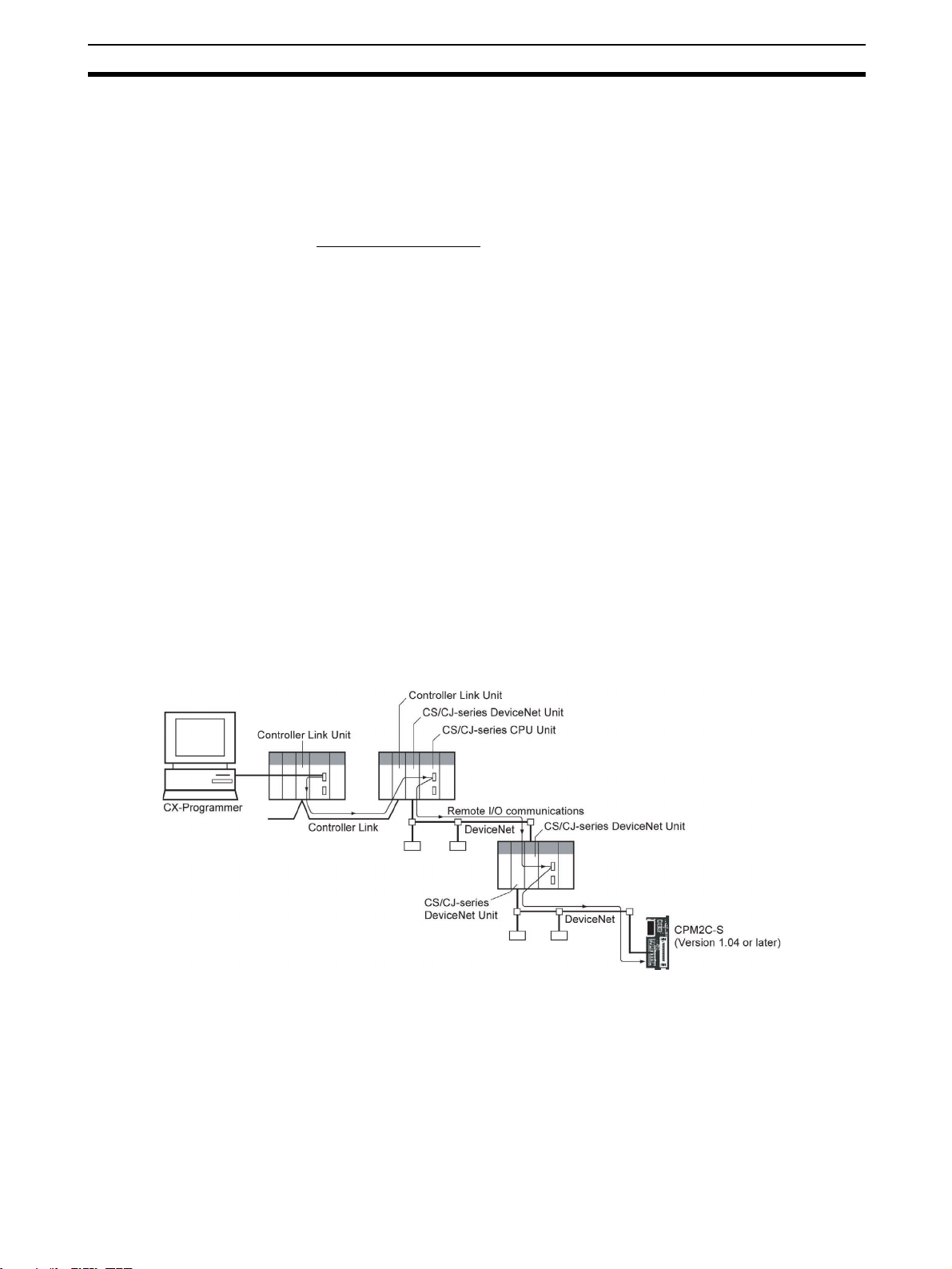
7 3-tier Communications with CX-Programmer
Communication between CX-Programmer and the CPM2C-S is possible over
a maximum of three network tiers, with the following limitation.
xxi
Page 22

3-tier Communications with CX-Programmer 7
CPM2C-S CPU Unit Limitation
For CPM2C-S CPU Units, the above feature is supported for all CPU Units
manufactured on 11 September 2001 or later. The manufacturing number for
these CPU Units is 1191O or later. Confirm the manufacturing number before
attempting to use this feature.
Reading Manufacturing Numbers
@@@@@
Factory code (A to Z or blank)
Year (For example 2000 = 0, 2001 = 1, and 2002 = 2)
Month (January to September = 1 to 9, October to December = X, Y, and Z)
Day of month (01 to 31)
Supported Communications
DeviceNet systems (A CS/CJ-series DeviceNet Unit must be mounted on CS/
CJ-series CPU Racks connected to the CPM2C-S.)
FA networks (Controller Link, SYSMAC LINK)
Office networks, Ethernet
Reference
FINS commands, such as CMND, SEND, and RECV, cannot be sent to or
received from the CPM2C-S.
xxii
Page 23

SECTION 1
Introduction
This section describes the special features and functions of the CPM2C-S, shows the possible system configurations,
and outlines the steps required before operation. Read this section first when using the CPM2C-S for the first time.
Refer to the CPM1/CPM1A/CPM2A/CPM2C/SRM1(-V2) Programming Manual (W353) for details on programming
operations.
1-1 CPM2C-S Features and Functions . . . . . . . . . . . . . . . . . . . . . . . . . . . . . . . . . 2
1-1-1 CPM2C-S Features . . . . . . . . . . . . . . . . . . . . . . . . . . . . . . . . . . . . . 2
1-1-2 Overview of CPM2C-S Functions . . . . . . . . . . . . . . . . . . . . . . . . . . 8
1-2 System Configurations . . . . . . . . . . . . . . . . . . . . . . . . . . . . . . . . . . . . . . . . . . 10
1-2-1 CPU Units and AC Power Supply Units . . . . . . . . . . . . . . . . . . . . . 10
1-2-2 CompoBus/S Interface . . . . . . . . . . . . . . . . . . . . . . . . . . . . . . . . . . . 11
1-2-3 CPU Unit, Expansion Units, and Expansion I/O Units . . . . . . . . . . 12
1-2-4 DeviceNet Interface . . . . . . . . . . . . . . . . . . . . . . . . . . . . . . . . . . . . . 15
1-2-5 Adapter Units . . . . . . . . . . . . . . . . . . . . . . . . . . . . . . . . . . . . . . . . . . 16
1-3 CPM2C-S Structure and Operation . . . . . . . . . . . . . . . . . . . . . . . . . . . . . . . . 17
1-3-1 CPM2C-S Structure . . . . . . . . . . . . . . . . . . . . . . . . . . . . . . . . . . . . . 17
1-3-2 Operating Modes . . . . . . . . . . . . . . . . . . . . . . . . . . . . . . . . . . . . . . . 18
1-3-3 Operating Mode at Startup. . . . . . . . . . . . . . . . . . . . . . . . . . . . . . . . 18
1-3-4 PC Operation at Startup . . . . . . . . . . . . . . . . . . . . . . . . . . . . . . . . . . 19
1-3-5 Cyclic Operation and Interrupts. . . . . . . . . . . . . . . . . . . . . . . . . . . . 21
1-4 Functions Listed by Usage . . . . . . . . . . . . . . . . . . . . . . . . . . . . . . . . . . . . . . . 25
1-5 Comparison with the CPM2C . . . . . . . . . . . . . . . . . . . . . . . . . . . . . . . . . . . . 27
1-6 Preparation for Operation. . . . . . . . . . . . . . . . . . . . . . . . . . . . . . . . . . . . . . . . 31
1
Page 24
CPM2C-S Features and Functions Section 1-1
1-1 CPM2C-S Features and Functions
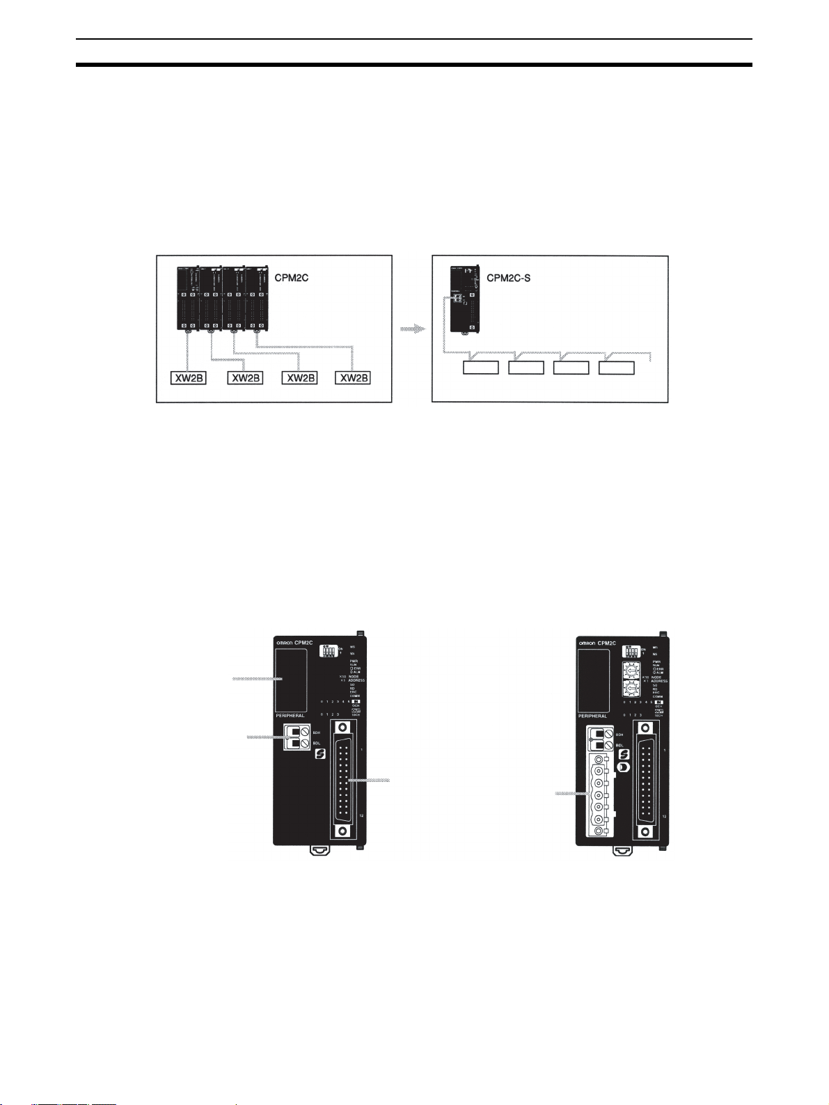
1-1-1 CPM2C-S Features
The CPM2C-S PCs are compact CPM2C PCs that have been equipped with
the functions of a CompoBus/S Master. The CPM2C-S incorporates a variety
of special features just like the CPM2C, including synchronized pulse control,
interrupt inputs, pulse outputs, and a clock function.
• The standard CompoBus/S interface increases the PC’s I/O capacity,
reduces wiring, and saves space.
CompoBus/S Slaves
• The CPM2C-S is a compact Unit, so it can be incorporated into almost
any machine. Furthermore, the CPM2C-S CPU Unit can be mounted in
any direction.
• The CPM2C-S100C-DRT and CPM2C-S110C-DRT are also equipped
with DeviceNet Slave functions to provide distributed control through a
DeviceNet connection with a host PC.
• The CPM2C-S itself can handle a wide range of machine control applications. In addition, the CPM2C-S is capable of communications with
devices such as personal computers and OMRON Programmable Terminals so it is ideal to use to expand or upgrade existing systems.
CPM2C-S100C
CPM2C-S110C
CPM2C-S100C-DRT
CPM2C-S110C-DRT
Communications
port
CompoBus/S
interface
I/O connector
DeviceNet
interface
• The CPM2C-S CPU Unit has a total of 10 I/O points: 6 inputs and 4 transistor outputs. Up to 3 CPM2C-series Expansion I/O Units can be connected for a maximum I/O capacity of 106 I/O points with three 32-point
Expansion I/O Units. It is possible to connect up to 362 I/O points by adding Slaves through the CompoBus/S system.
• The communications port can be used simultaneously as two ports:
Peripheral and RS-232C. The peripheral port supports Programming
Devices, Host Link, and no-protocol communications. The RS-232C port
2
Page 25
CPM2C-S Features and Functions Section 1-1
supports Host Link, no-protocol (serial), 1:1 Link, and 1:1 NT Link communications.
• Connect up to 3 Expansion Units such as CPM2C-series Analog I/O
Units, Temperature Sensor Units, or CompoBus/S I/O Link Units for CompoBus/S Slave functions.
CompoBus/S Master
Functions
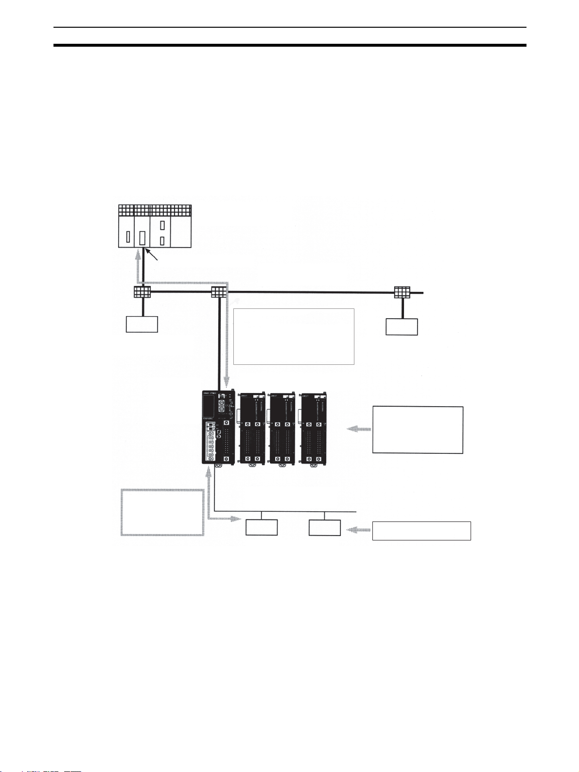
Example System Configuration
DeviceNet Slave
Up to 32 CompoBus/S Slaves can be connected to create a Remote I/O Link
with up to 256 I/O points. It is easy to build an efficient, long-range distributed
system with less wiring by connecting CompoBus/S I/O Terminals, Analog
Terminals, Sensor Terminals, and Bit Chain Terminals.
CS1, C200HX/HE/HG,
CVM1, or CV-series PC
DeviceNet Unit (Master)
As a DeviceNet Slave, the
CPM2C-S supports remote I/O
communications with up to 32
input words and 32 output words
as well as explicit message
communications.
CPM2C-S
DeviceNet transmission line
Expansion (I/O) Unit (3 max.)
DeviceNet Slave
I/O control, interrupt inputs, high-speed counters, pulse outputs, synchronized pulse control,
and analog I/O
As a CompoBus/S
Master, the CPM2C-S
can control remote
I/O (up to 256 points)
on Slaves.
DeviceNet Slave
Functions
(-DRT Models Only)
CompoBus/S transmission line
I/O control and analog I/O
CompoBus/S Slaves
When the CPM2C-S is used as a DeviceNet Slave, an I/O Link of up to 1,024
points (512 inputs and 512 outputs) can be created with the Master. The input
and output areas used in the I/O Link can be allocated independently and the
data areas, starting addresses, and size of these Read/Write areas can be
specified freely. (The Read/Write areas can be set in the PC Setup or using
the DeviceNet Configurator.)
Explicit message communications can be initiated from the Master to read or
write data in any data area in the CPM2C-S.
3
Page 26
CPM2C-S Features and Functions Section 1-1
Basic Functions
CPU Unit Variations The CPM2C-S PCs are one-piece PCs with 10 I/O points (6 inputs and 4 out-
puts) in a built-in connector. There are 2 types of outputs available (sinking
transistor outputs, and sourcing transistor outputs). All CPM2C-S PCs require
a 24-VDC power supply.
Expansion I/O Units and
CompoBus/S Slaves
CompoBus/S Slaves and up to 3 Expansion I/O Units can be connected to the
CPU Unit to increase the PC’s I/O capacity to a maximum of 362 I/O points.
There are 23 different Expansion I/O Units available, including Units with 32
I/O points, 24 I/O points, 20 I/O points, 10 I/O points, 8 input points, 8 output
points, 16 inputs points, and 16 output points. The maximum I/O capacity of
106 I/O points is achieved by connecting three 32-point Expansion I/O Units
to the CPU Unit.
The CompoBus/S Master functions allow I/O Slaves to be connected providing an additional capacity of up to 256 I/O points (128 inputs and 128 outputs.)
Share Programming
Devices
Either a Programming Console or the CX-Programmer (version 2.1 or later)
can be used to program and monitor the CPM2C-S. Programs created on the
SYSMAC-CPT or SYSMAC Support Software can also be used.
Built-in Motor Control Capability
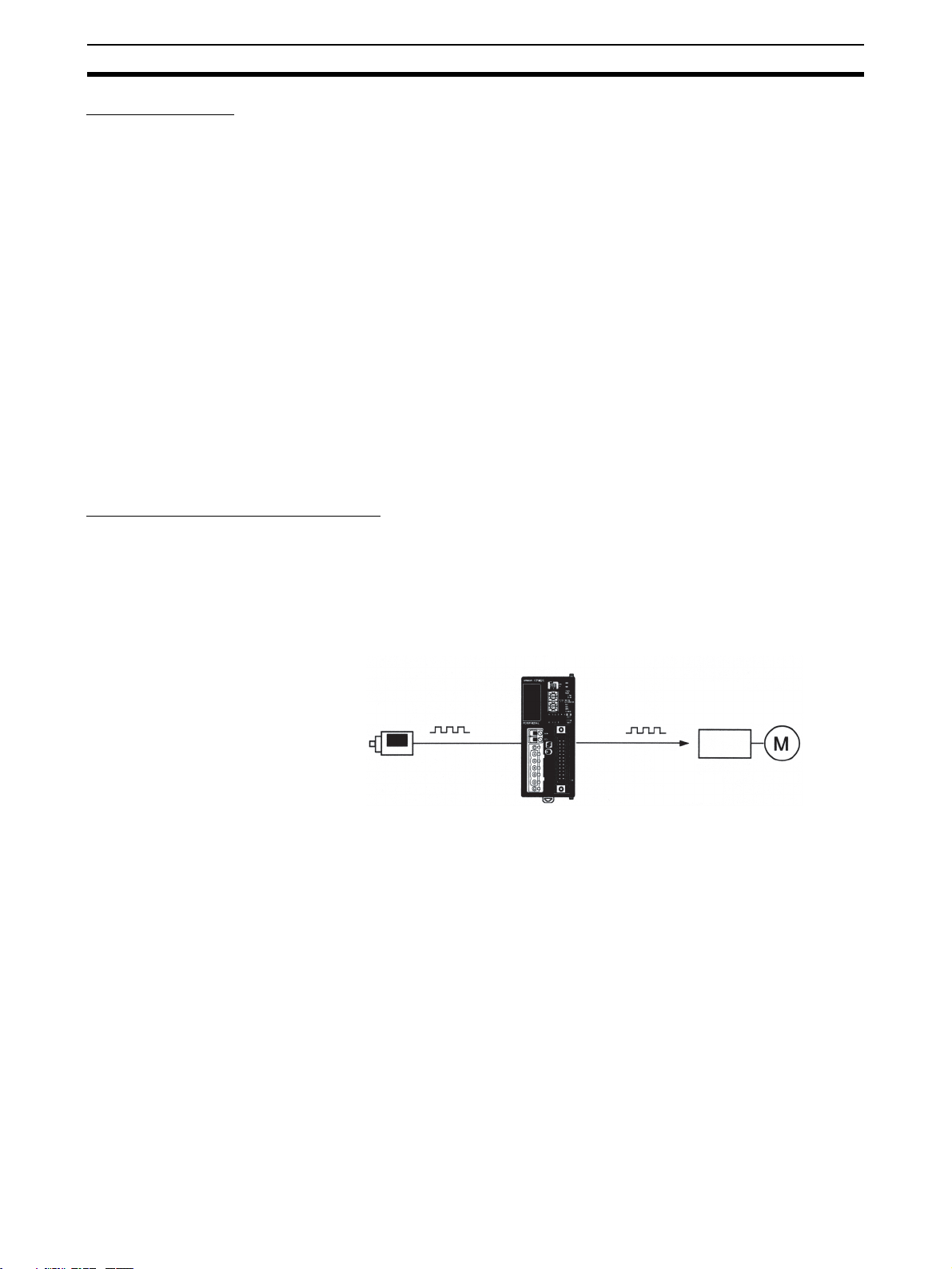
Synchronized Pulse
Control
Synchronized pulse control provides an easy way to synchronize the operation of a peripheral piece of equipment with the main equipment. The output
pulse frequency can be controlled as some multiple of the input pulse frequency, allowing the speed of a peripheral piece of equipment (such as a supply conveyor) to be synchronized with the speed of the main piece of
equipment.
CPM2C-S
High-speed Counters and
Interrupts
Encoder
Pulses are output as a fixed multiple of the input frequency.
Motor driver
Motor
The CPM2C-S has a two kinds of high-speed counter inputs. The high-speed
counter input has a response frequency of 20 kHz/5 kHz and the interrupt
inputs (in counter mode) have a response frequency of 2 kHz.
• The single high-speed counter can be used in any one of the four input
modes: differential phase mode (5 kHz), pulse plus direction input mode
(20 kHz), up/down pulse mode (20 kHz), or increment mode (20 kHz).
Interrupts can be triggered when the count matches a set value or falls
within a specified range.
One high-speed counter can be used.
• The interrupt inputs (counter mode) can be used for incrementing
counters or decrementing counters (2 kHz) and trigger an interrupt (executing the interrupt program) when the count matches the target value.
Two interrupt inputs can be used.
4
Page 27

CPM2C-S Features and Functions Section 1-1
Easy Position Control with
Pulse Outputs
CPM2C-S PCs have two outputs that can produce 10 Hz to 10 kHz pulses
(single-phase outputs).
• When used as single-phase pulse outputs, there can be two outputs with
a frequency range of 10 Hz to 10 kHz with a fixed duty ratio or 0.1 to
999.9 Hz with a variable duty ratio (0 to 100% duty ratio).
• When used as pulse plus direction or up/down pulse outputs, there can
be just one output with a frequency range of 10 Hz to 10 kHz.
High-speed Input Capabilities for Machine Control
High-speed Interrupt Input
Function
Quick-response Input
Function
Stabilizing Input Filter
Function
The CPU Units have 2 inputs that can be used as interrupt inputs. These
inputs are shared with quick-response inputs and interrupt inputs in counter
mode and have a minimum input signal width of 50 µs and response time of
0.3 ms. When an interrupt input goes ON, the main program is stopped and
the interrupt program is executed.
The CPU Units have 2 inputs that can be used as quick-response inputs to
reliably read inputs with a signal width as short as 50 µs regardless of the
cycle time. These inputs are shared with interrupt inputs and interrupt inputs
in counter mode.
The input time constant for all inputs can be set to 1 ms, 2 ms, 3 ms, 5 ms,
10 ms, 20 ms, 40 ms, or 80 ms. The effects of chattering and external noise
can be reduced by increasing the input time constant.
Analog I/O Supported by Expansion Units and CompoBus/S Master Functions
Analog I/O Units Up to 3 optional Analog I/O Units can be connected to the CPM2C-S. For
each Analog I/O Unit mounted to the Unit, 2 analog input points and 1 analog
output point are available. By mounting 3 Analog I/O Units, a maximum of 6
analog input points and 3 analog output points can be made available. (By
using a combination of the PID(––) instruction and PWM(––) instruction, time
proportional control is possible.)
• The ranges supported for analog input signals are 0 to 5 V, 0 to 10 V, –10
to 10 V, 0 to 20 mA, and 4 to 20 mA, and the resolution is 1/6000 (full
scale). The averaging function and power interruption detection function
can be used.
• The ranges supported for analog output signals are 1 to 5 V, 0 to 10 V,
–10 to 10 V, 0 to 20 mA, and 4 to 20 mA, and the resolution is 1/6000 (full
scale).
Analog I/O Terminals Up to 8 analog inputs and 8 analog outputs can be connected through a Com-
poBus/S Analog I/O Terminal.
Temperature Sensor Units Up to 3 optional Temperature Sensor Units can be mounted to the CPM2C-S.
There are 2 models of Temperature Sensor Unit: One for input from a thermocouple sensor and one for input from a platinum resistance thermometer sensor. There are 2 input points on each Temperature Sensor Unit.
• Thermocouple inputs (and measurement ranges): K (–200 to 1,300°C), K
(0.0 to 500.0°C), J (-100 to 850°C), and J (0.0 to 400.0°C).
• Platinum resistance thermometer inputs (and measurement ranges):
Pt100 (–200.0 to 650.0°C), JPt100 (–200.0 to 650.0°C).
5
Page 28
CPM2C-S Features and Functions Section 1-1
Other Functions
Interval Timer Interrupts The interval timer can be set between 0.5 and 319,968 ms and can be set to
generate just one interrupt (one-shot mode) or periodic interrupts (scheduled
interrupt mode).
Calendar/Clock The clock (accuracy within 1 minute/month) can be read from the program to
show the current year, month, day, day of the week, and time. The clock can
be set from a Programming Device (such as a Programming Console) or the
time can be adjusted by rounding up or down to the nearest minute.
Long-term Timer TIML(––) is a long-term timer that accommodates set values up to 99,990
seconds (27 hours, 46 minutes, 30 seconds). When combined with the SECONDS TO HOURS conversion instruction (HMS(––)), the long-term timer provides an easy way to control equipment scheduling.
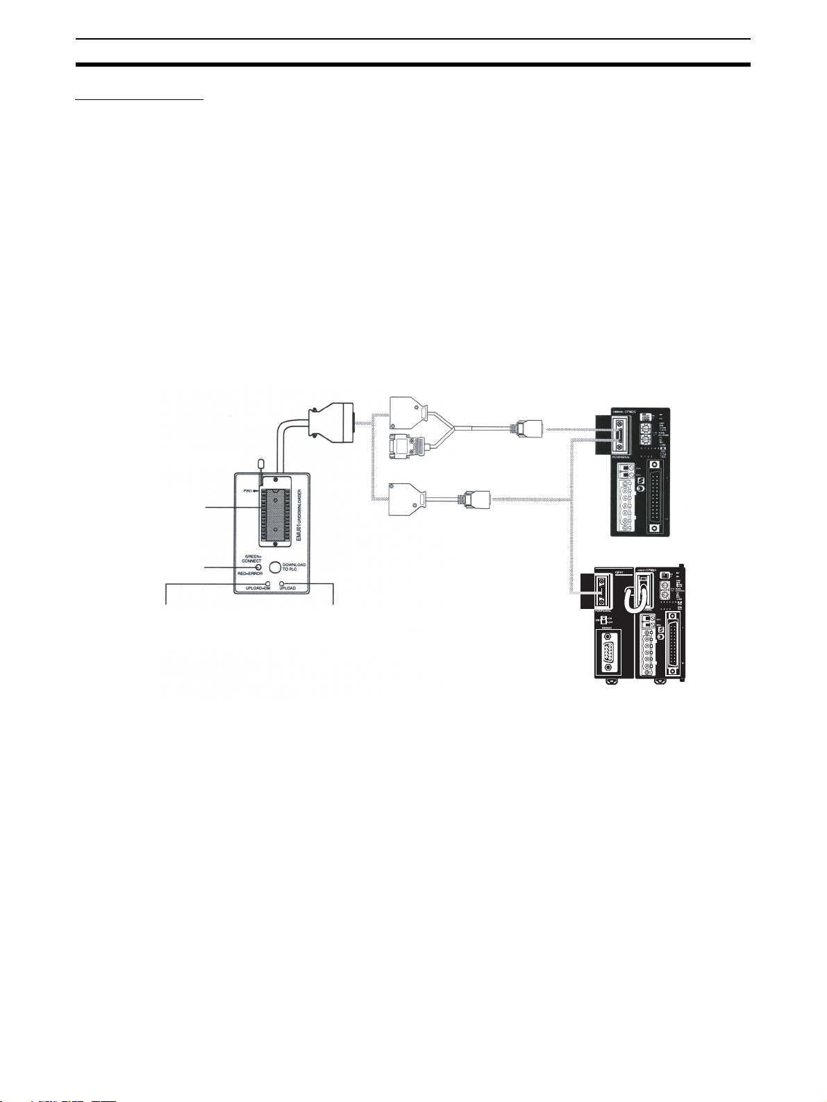
Expansion Memory Unit The CPM1-EMU01-V1 Expansion Memory Unit is a program loader for small-
size or micro PCs. Using the CPM1-EMU01-V1, simple on-site transfer of
user programs and data memory (DM 6144 to DM 6655) is possible with PCs.
CPM2C-S
Expansion Memory Unit
EEPROM
Indicator
UPLOAD+DM Button UPLOAD Button
CPM2C-CN111
CS1W-CN114
CPM2C-S
CPM2C-CIF01-V1
6
Page 29
CPM2C-S Features and Functions Section 1-1
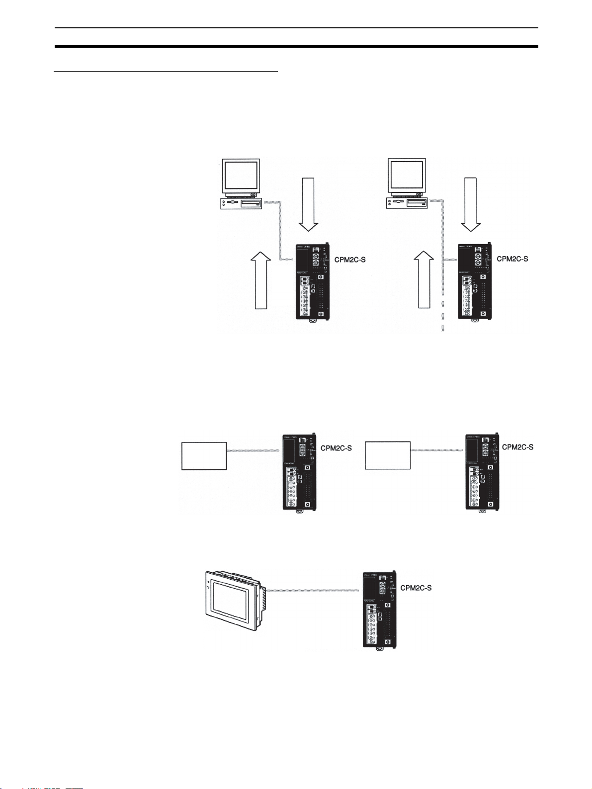
Complete Communications Capabilities
Host Link A Host Link connection can be made through the PC’s communications port
used as a RS-232C or peripheral port. A personal computer or Programmable
Terminal connected in Host Link mode can be used for operations such as
reading/writing data in the PC’s I/O memory or reading/changing the PC’s
operating mode.
1:1 Host Link Communications 1:N Host Link Communications
No-protocol
Communications
Responses
Commands
Responses
(Up to 32 PCs can be connected.)
Commands
The TXD(48) and RXD(47) instructions can be used in no-protocol mode to
exchange data with standard serial devices. For example, data can be
received from a bar code reader or transmitted to a serial printer. The serial
devices can be connected to the communications port as a RS-232C or
peripheral port.
Inputting data from
a bar code reader
Bar code
reader
Outputting data to
a serial printer
Serial
printer
High-speed 1:1 NT Link
Communications
OMRON PT
In a 1:1 NT Link, an OMRON Programmable Terminal (PT) can be connected
directly to the CPM2C-S. The PT must be connected to the communications
port as an RS-232C port (not as a peripheral port).
7
Page 30

CPM2C-S Features and Functions Section 1-1
One-to-one PC Link A CPM2C-S can be linked directly to another CPM2C-S, CQM1, CPM1,
CPM1A, CPM2A, CPM2C, SRM1(-V2), C200HS, or C200HX/HG/HE PC. The
1:1 PC Link allows automatic data link connections. The PC must be connected to the communications port as an RS-232C port (not as a peripheral
port).
1-1-2 Overview of CPM2C-S Functions
Main function Variations/Details
CompoBus/S Master
functions
DeviceNet Slave
functions
Interrupts Interrupt inputs
High-speed counters High-speed counter
• Remote I/O devices can be allocated up to 256 I/O points (128 inputs and 128 outputs) in
input area IR 020 to IR 027 and output area IR 030 to IR 037.
• The node numbers can be set to 0 to 7 (128-point mode) or 0 to 15 (256-point mode).
• The communications mode can be set to high-speed mode (max. length 100 m) or long-dis-
tance mode (max. length 500 m).
• Up to 64 words (32 input words and 32 output words) can be allocated to the DeviceNet
Master’s I/O. The Master’s I/O can be allocated to the following data areas.
IR 000 to IR 049
IR 200 to IR 227
DM 0000 to DM 2047
LR 00 to LR 15
HR 00 to HR 19
AR 00 to AR 23 (CPM2C → Master; read-only)
TC 000 to TC 255
• Explicit message communications are supported. Any CPM2C-S data area can be
accessed from the DeviceNet Master.
• The communications speed can be set to 500 kbps (total network length 100 m max.),
250 kbps (total network length 250 m max.), or 125 kbps (total network length 500 m max.).
2 inputs
Response time: 50 µs
Interval timer interrupts
1 input
Set value: 0.5 to 319,968 ms
Precision: 0.1 ms
1 input, see note 1.
Differential phase mode (5 kHz)
Pulse plus direction input mode (20 kHz)
Up/down input mode (20 kHz)
Increment mode (20 kHz)
Interrupt inputs (counter mode)
2 inputs
Incrementing counter (2 kHz)
Decrementing counter (2 kHz)
Scheduled interrupts
One-shot interrupt
No interrupt
Count-check interrupt
(An interrupt can be generated when the
count equals the set value or the count lies
within a preset range.)
No interrupt
Count-up interrupt
8
Page 31

CPM2C-S Features and Functions Section 1-1
Main function Variations/Details
Pulse outputs • 2 outputs:
Synchronized pulse
control
Quick-response input 2 inputs in CPU Units with 10 I/O points, 4 inputs in CPU Units with 20 I/O points
Input time constant Determines the input time constant for all inputs. (Settings: 1, 2, 3, 5, 10, 20, 40, or 80 ms)
Calendar/Clock Shows the current year, month, day of the week, day of the month, hour, minute, and second.
Expansion Unit functions Analog I/O functions using CPM2C-MAD11 Analog I/O Unit
Single-phase pulse output without acceleration/deceleration (See note 2.)
10 Hz to 10 kHz
• 2 outputs:
Variable duty ratio pulse output (See note 2.)
0.1 to 999.9 Hz, duty ratio 0 to 100%
• 1 output:
Pulse output with trapezoidal acceleration/deceleration (See note 2.)
Pulse plus direction output, up/down pulse output, 10 Hz to 10 kHz
1 point, see notes 1 and 2.
Input frequency range: 10 to 500 Hz, 20 Hz to 1 kHz, or 300 Hz to 20 kHz
Output frequency range: 10 Hz to 10 kHz
Minimum input signal width: 50 µs
• Two analog inputs: Input range of 0 to 5 V, 1 to 5 V, 0 to 10 V, –10 to 10 V, 0 to 20 mA,
or 4 to 20 mA
• One analog output: Output range of 1 to 5 V, 0 to 10 V, –10 to 10 V, 0 to 20 mA,
or 4 to 20 mA
Temperature sensing functions using CPM2C-TS001/101 Temperature Sensor Unit
• Thermocouple input (measurement range): K (−200 to 1,300°C)
K (0.0 to 500.0°C)
J (–100 to 850°C)
J (0.0 to 400.0°C)
• Platinum resistance thermometer (measurement range): Pt100 (–200.0 to 650.0°C)
JPt100 (–200.0 to 650.0°C)
CompoBus/S Slave functions using CPM2C-SRT21 CompoBus/S I/O Link Unit
Data exchange with the Master Unit via 8 inputs and 8 outputs.
Note 1. This input is shared by the high-speed counter and synchronized pulse
control functions.
2. This output is shared by the pulse output and synchronized pulse control
functions.
9
Page 32

System Configurations Section 1-2
1-2 System Configurations
1-2-1 CPU Units and AC Power Supply Units
CPM2C-S CPU Units
Name Inputs Outputs Model
CPU Unit with CompoBus/S Master
Functions
CPU Unit with CompoBus/S Master
and DeviceNet Slave Functions
CPM2C-S100C
CPM2C-S110C
6 24-VDC inputs 4 sinking transistor outputs CPM2C-S100C
4 sourcing transistor outputs CPM2C-S110C
4 sinking transistor outputs CPM2C-S100C-DRT
4 sourcing transistor outputs CPM2C-S110C-DRT
CPM2C-S100C-DRT
CPM2C-S110C-DRT
AC Power Supply Unit (Optional)
Name Ratings Model
AC Power Supply Unit 100 to 240 VAC input
24 VDC, 600 mA output
Note General-purpose power supplies such as the S82J-series and S82K-series
Power Supplies can also be used.
AC Power Supply Unit
CPM2C-PA201
10
Page 33

System Configurations Section 1-2
1-2-2 CompoBus/S Interface
The standard built-in CompoBus/S interface increases the PC’s I/O capacity,
reduces wiring, and saves space. Up to 32 CompoBus/S Slaves can be connected to create a Remote I/O Link with up to 256 I/O points. It is easy to build
an efficient, long-range distributed system with less wiring by connecting
CompoBus/S I/O Terminals, Analog Terminals, Sensor Terminals, and Bit
Chain Terminals.
CompoBus/S transmission line
Terminator
Slave Slave Slave
32 or 16 Slaves max. (selectable)
• The max. number of Slaves that can be connected through CompoBus/S
can be set to 16 or 32 Slaves. The following tables show how the max.
number of Slaves and communications mode settings affect the communications response time as well as the communications distance and
communications speed.
CompoBus/S Communications Response Time
Communications mode Max. number of Slaves Communications
High-speed mode 16 0.5 ms
32 0.8 ms
Long-distance mode 16 4.0 ms
32 6.0 ms
response time
Communications Distance
Cable Mode Main line
2-conductor
VCTF cable
4-conductor
VCTF cable
High-speed Communications Mode
Long-distance Communications Mode
High-speed Communications Mode
Long-distance Communications Mode
length
100 m max. 3 m max. 50 m max.
500 m max. 6 m max. 120 m max.
30 m max.
(See note.)
Flexibly branched, provided that the
total length of cable is a maximum of
200 m.
Branch
line length
3 m max.
(See note.)
Tot al
branch
line length
30 m max.
(See note.)
11
Page 34

System Configurations Section 1-2
Cable Mode Main line
Special Flat
Cable
High-speed Communications Mode
Long-distance Communications Mode
length
30 m max.
(See note.)
Flexibly branched, provided that the
total length of cable is a maximum of
200 m.
line length
3 m max.
(See note.)
Note When 4-conductor VCTF cable or Special Flat Cable is used to connect fewer
than 16 Slaves, the main line can be up to 100 m long and the total branch
line length can be up to 50 m in High-speed Communications Mode. (These
are the same conditions as when 2-conductor VCTF cable is used.)
• Refer to 5-2 Remote I/O Communications for a list of compatible Slaves.
1-2-3 CPU Unit, Expansion Units, and Expansion I/O Units
A series of up to 3 Expansion I/O Units or Expansion Units can be connected
to the expansion I/O connector on the CPU Unit.
There are three types of Expansion Units available: Analog I/O Unit, Temperature Sensor Unit, and CompoBus/S I/O Link Unit.
CPU Unit
Expansion I/O Unit
or Expansion Unit
Branch
Tot al
branch
line length
30 m max.
(See note.)
Expansion I/O Connector
(with cover)
Expansion I/O Connector
(input side)
A PC with 106 I/O points (the maximum) can be assembled by connecting
three 32-point Expansion I/O Units to a CPU Unit.
CPM2C-S100C-DRT
(6 inputs, 4 outputs)
1 Unit 3 Units 54 inputs, 52 outputs
CPM2C-32EDTC
(16 inputs, 16 outputs)
Expansion I/O Units Units with Relay Outputs (via Terminal Block)
10 I/O Points 8 Output Points20 I/O Points
Expansion I/O Connector
(output side, no cover)
12
Unit I/O Inputs Outputs Model
10 I/O points 6 inputs (24 VDC) 4 relay outputs CPM2C-10EDR
20 I/O points 12 inputs (24 VDC) 8 relay outputs CPM2C-20EDR
8 output points --- 8 relay outputs CPM2C-8ER
Page 35

System Configurations Section 1-2
Units with Transistor Outputs via Fujitsu-compatible Connector
8 Output Points 16 Input Points 16 Output Points8 Input Points32 I/O Points24 I/O Points
Unit I/O Inputs Outputs Model
24 I/O points 16 inputs (24 VDC) 8 transistor outputs (sinking) CPM2C-24EDTC
8 transistor outputs (sourcing) CPM2C-24EDT1C
32 I/O points 16 inputs (24 VDC) 16 transistor outputs (sinking) CPM2C-32EDTC
16 transistor outputs (sourcing) CPM2C-32EDT1C
8 input points 8 inputs (24 VDC) --- CPM2C-8EDC
16 input points 16 inputs (24 VDC) --- CPM2C-16EDC
8 output points --- 8 transistor outputs (sinking) CPM2C-8ETC
--- 8 transistor outputs (sourcing) CPM2C-8ET1C
16 output points --- 16 transistor outputs (sinking) CPM2C-16ETC
--- 16 transistor outputs (sourcing) CPM2C-16ET1C
Units with Transistor Outputs via MIL Connector
32 I/O Points24 I/O Points
Unit I/O Inputs Outputs Model
24 I/O points 16 inputs (24 VDC) 8 transistor outputs (sinking) CPM2C-24EDTM
32 I/O points 16 inputs (24 VDC) 16 transistor outputs (sinking) CPM2C-32EDTM
8 input points 8 inputs (24 VDC) --- CPM2C-8EDM
16 input points 16 inputs (24 VDC) --- CPM2C-16EDM
8 output points --- 8 transistor outputs (sinking) CPM2C-8ETM
--- 8 transistor outputs (sourcing) CPM2C-8ET1M
16 output points --- 16 transistor outputs (sinking) CPM2C-16ETM
--- 16 transistor outputs (sourcing) CPM2C-16ET1M
8 Input or
8 Output Points
8 transistor outputs (sourcing) CPM2C-24EDT1M
16 transistor outputs (sourcing) CPM2C-32EDT1M
16 Input or
16 Output Points
13
Page 36

System Configurations Section 1-2
Expansion Units
CPM2C-MAD11
Analog I/O Unit
CPM2C-TS001/101
Temperature Sensor Unit
CPM2C-SRT21
CompoBus/S I/O Link Unit
Unit Max. number
Analog I/O Unit 2 analog inputs
1 analog output
Temperature Sensor Unit
CompoBus/S I/O
Link Unit
2 thermocouple
inputs
2 platinum resistance thermometer
inputs
8 input points and 8
output points for
the built-in outputs
and inputs of the
Master Unit
of Units
Inputs Outputs Model
4 2 points, 2 words
allocated
4 2 points, 2 words
allocated
2 points, 2 words
allocated
5 8 points, 1 word
allocated
(Inputs from the
Master)
1 point, 1 word allocated
--- CPM2C-TS001
--- CPM2C-TS101
8 points, 1 word
allocated
(Outputs to the
Master)
CPM2C-MAD11
CPM2C-SRT21
14
Page 37

System Configurations Section 1-2
1-2-4 DeviceNet Interface
A CPM2C-S100C-DRT or CPM2C-S110C-DRT can be used as a DeviceNet
Slaves to create an I/O Link of up to 1,024 points (512 inputs and 512 outputs)
with the DeviceNet Master. The input and output areas used in the I/O Link
can be allocated independently and the data areas, starting addresses, and
size of these Read/Write areas can be specified freely. (The Read/Write areas
can be set in the PC Setup or using the DeviceNet Configurator.)
Explicit message communications can be initiated from the Master to read or
write data in any data area in the CPM2C-S.
CS1, C200HX/HG/HE(-Z),
CVM1, or CV-series PC
DeviceNet Unit (Master)
DeviceNet transmission line
As a DeviceNet Slave, the
CPM2C-S supports remote I/O
DeviceNet Slave
communications with up to 32 input
words and 32 output words as well
as explicit message communications.
DeviceNet Slave
Expansion (I/O) Units (3 max.)
CompoBus/S transmission line
CompoBus/S Slaves
Note Refer to the DeviceNet Masters Operation Manual (W379) for more details on
OMRON DeviceNet Masters.
15
Page 38

System Configurations Section 1-2
t
1-2-5 Adapter Units
Peripheral/RS-232C Adapter Unit RS-422/RS-232C Adapter Uni
Unit Conversion Model
Peripheral/RS-232C Adapter Unit CPU Unit’s communications port →
Peripheral port + RS-232C port
RS-422/RS-232C Adapter Unit CPU Unit’s communications port →
RS422 port + RS-232C port
Note 1. The CPM2C-CIF01-V1 cannot be used with any PC model other than a
CPM2C or CPM2C-S.
2. Although a CPM2C-CN111 can be connected to a CPM2C-CIF01-V1, it is
not possible to use the peripheral port and the RS-232C port on the
CPM2C-CN111 simultaneously. If an attempt is made to use both ports simultaneously, it may be impossible to communicate normally and equipment malfunction may result.
CPM2C-CIF01-V1
CPM2C-CIF11
16
Page 39

CPM2C-S Structure and Operation Section 1-3
1-3 CPM2C-S Structure and Operation
1-3-1 CPM2C-S Structure
The following diagram shows the internal structure of the CPU Unit.
DeviceNet
Master
External
input
devices
DeviceNet
interface
Input circuits
Communications
port
Settings
Program
Settings
Communications
switches
I/O memory
PC Setup
Settings
CompoBus/S
interface
Output circuits
CompoBus/S
Slaves
External
output
devices
I/O Memory The program reads and writes data in this memory area during execution.
Part of the I/O memory contains the bits that reflect the status of the PC’s
inputs and outputs. Parts of the I/O memory are cleared when the power is
turned ON and other parts are retained.
Note Refer to SECTION 4 Memory Areas for more details on I/O memory.
Program This is the program written by the user. The CPM2C-S executes the program
cyclically. (Refer to 1-3-5 Cyclic Operation and Interrupts for details.)
The program can be divided broadly into two parts: the “main program” that is
executed cyclically and the “interrupt programs” that are executed only when
the corresponding interrupt is generated.
PC Setup The PC Setup contains various startup and operating parameters. The PC
Setup parameters can be changed from a Programming Device only; they
cannot be changed from the program.
Some parameters are accessed only when PC’s power supply is turned ON
and others are accessed regularly while the power is ON. It will be necessary
to turn the power OFF and then ON again to enable a new setting if the
parameter is accessed only when the power is turned ON.
Note Refer to 4-6 PC Setup for details on the PC Setup.
Communications
Switches
The Communications Switches determine whether the peripheral port and
RS-232C port connected through the communications port operate with the
17
Page 40

CPM2C-S Structure and Operation Section 1-3
standard communications settings or the communications settings in the PC
Setup.
1-3-2 Operating Modes
CPM2C-S CPU Units have 3 operating modes: PROGRAM, MONITOR, and
RUN.
PROGRAM Mode The program cannot be executed in PROGRAM mode. This mode is used to
perform the following operations in preparation for program execution.
• Changing initial/operating parameters such as those in the PC Setup
• Writing, transferring, or checking the program
• Checking wiring by force-setting and force-resetting I/O bits
!Caution The PC continues to refresh I/O bits even if the PC is in PROGRAM mode, so
devices connected to output points may operate unexpectedly if the corresponding output bit is turned ON by transferring I/O memory or force-setting
output bits from a Programming Device.
When output bits are allocated to the DeviceNet I/O Link Write Area, data written to the output bits through DeviceNet is effective immediately and the output bits may go ON even if the PC is in PROGRAM mode. Do not change the
status of output bits from a Programming Device or DeviceNet unless it is safe
to do so.
MONITOR Mode The program is executed in MONITOR mode and the following operations can
be performed from a Programming Device. In general, MONITOR mode is
used to debug the program, test operation, and make adjustments.
• Online editing
• Monitoring I/O memory during operation
• Force-setting/force-resetting I/O bits, changing set values, and changing
present values during operation
RUN Mode The program is executed at normal speed in RUN mode. Operations such as
online editing, force-setting/force-resetting I/O bits, and changing set values/
present values cannot be performed in RUN mode, but the status of I/O bits
can be monitored.
1-3-3 Operating Mode at Startup
The operating mode of the CPM2C-S when the power is turned ON depends
upon the setting of pin 4 on the DIP switch on the front of the CPM2C-S, the
PC Setup settings in DM 6600, and the Programming Console’s mode switch
setting if a Programming Console is connected.
PC Setup setting Operating mode
Word Bits Setting
DM 6600 08 to 15 00 (Hex) See note 1.
01 (Hex) Startup mode is the same as the operating mode
02 (Hex) Startup mode is determined by bits 00 to 07.
00 to 07 00 (Hex) PROGRAM mode
01 (Hex) MONITOR mode
02 (Hex) RUN mode
before power was interrupted.
18
Page 41

CPM2C-S Structure and Operation Section 1-3
Note 1. The operating mode at startup depends upon the setting of DIP switch pin
4 and the Programming Device connected to the communications port (peripheral port).
Programming Device Pin 4 OFF Pin 4 ON
None PROGRAM mode RUN mode
Programming Console Operating mode set on the Programming Console’s
mode switch
Other device PROGRAM mode
The default setting for bits 08 to 15 of DM 6600 is 00. If this default setting
is used and pin 4 is OFF, the CPM2C-S will automatically start operating
in RUN mode when the power is turned ON.
2. If pin 4 is OFF and only an RS-232C cable is connected to the communications port (i.e., there is no peripheral port connection), the CPM2C-S will
automatically start operating in RUN mode when the power is turned ON.
Example Cable Connections:
CS1W-CN118 and XW2Z-200S/500S
CS1W-CN118 and XW2Z-200S-V/500S-V
CPM2C-CN111 and XW2Z-200S/500S (no peripheral port connection)
CPM2C-CN111 and XW2Z-200S-V/500S-V (no peripheral port connection)
1-3-4 PC Operation at Startup
Time Required for
Initialization
Power OFF Operation Minimum Power Supply Voltage
The time required for startup initialization depends on several factors, such as
the operating conditions (including power supply voltage, system configuration, and ambient temperature) and the program contents.
The PC will stop and all outputs will be turned OFF if the power supply voltage
falls below 85% of the rated value.
Momentary Power Interruption
A power interruption will not be detected and CPU Unit operation will continue
if the power interruption lasts less than 2 ms.
A power interruption may or may not be detected for power interruptions
somewhat longer than 2 ms.
When a power interruption is detected, the CPU Unit will stop operating and
all outputs will be turned OFF.
Automatic Reset
Operation will restart automatically when the power supply voltage is restored
to more than 85% of the rated voltage.
Timing Chart of Power OFF Operation
The power interruption detection time is the time required for a power interruption to be detected after the power supply voltage drops below 85% of the
rated value.
1,2,3... 1. Minimum power interruption detection time
Power interruptions that are shorter than 2 ms will not be detected.
19
Page 42

CPM2C-S Structure and Operation Section 1-3
2. Undetermined additional time
Power interruptions only slightly longer than the minimum power interruption time may not be detected.
85% of rated voltage
Detection of
wepo r interruption
Program execution
CPU reset signal
1. Minimum time
Executing Stopped
CPU Unit operation will
continue if voltage is
restored in this region.
2. Additional
time
CPU Unit operation may
continue if voltage is
restored in this region.
Note If the power supply voltage fluctuates around 85% of the PC’s rated voltage,
PC operation may stop and restart repeatedly. When repeated stopping and
starting will cause problems with the controlled system, set up a protective circuit such as a circuit that shuts OFF the power supply to sensitive equipment
until the power supply voltage returns to the rated value.
20
Page 43

CPM2C-S Structure and Operation Section 1-3
1-3-5 Cyclic Operation and Interrupts
Basic CPU Operation Initialization processing is performed when the power is turned ON. If there
are no initialization errors, the overseeing processes, program execution, I/O
refreshing, and communications port servicing are performed repeatedly
(cyclically).
• Check hardware.
Startup initialization
Overseeing
processes
• Check memory.
• Read data from flash memory (program,
read-only DM data, and PC Setup settings).
• Check for battery error.
• Preset the watch (maximum) cycle time.
• Check program memory.
• Refresh bits for expansion functions.
CompoBus/S
input refreshing
Program execution
Cycle time
calculation
CompoBus/S
PC cycle time
output refreshing
I/O refreshing
DeviceNet
I/O refreshing
• Read input data from CompoBus/S
remote I/O Slaves.
• Execute the program.
(Refer to the Programming Manual (W353) for
details on cycle time and I/O response times.)
• Wait for minimum cycle time if a minimum
cycle time has been set in the PC Setup
(DM 6619).
• Calculate cycle time.
• Write output data to CompoBus/S
remote I/O Slaves.
• Read input data from input bits.
• Write output data to output bits.
• Exchange I/O data with the DeviceNet Master.
(-DRT versions only)
DeviceNet message
communications
RS-232C port
servicing
Peripheral port
servicing
• Perform explicit message communications
with the DeviceNet Master.
(-DRT versions only)
• Perform RS-232C port communications
processing. (Can be changed in DM 6616.)
• Perform peripheral port communications
processing. (Can be changed in DM 6617.)
The cycle time can be read from a Programming Device.
AR 14 contains the maximum cycle time and AR 15 contains the present
cycle time in multiples of 0.1 ms.
21
Page 44

CPM2C-S Structure and Operation Section 1-3
The cycle time will vary slightly depending on the processing being performed
in each cycle, so the calculated cycle time will not always match the actual
cycle time.
Program Execution in
Cyclic Operation
The following diagram shows the cyclic operation of the CPM2C-S when the
program is being executed normally.
Normally, the results of program execution are transferred to I/O memory just
after program execution (during I/O refreshing), but IORF(97) can be used to
refresh a specified range of I/O words during program execution. The specified range of I/O words will be refreshed when IORF(97) is executed.
The cycle time is the sum of the time required for program execution, I/O
refreshing, and communications port servicing.
A minimum cycle time (1 to 9,999 ms) can be set in the PC Setup (DM 6619).
When a minimum cycle time has been set, CPU operation is paused after program execution until the minimum cycle time is reached. CPU operation will
not be paused if the actual cycle time is longer than the minimum cycle time
set in DM 6619.
Note A fatal error will occur and PC operation will stop if a maximum cycle time has
been set in the PC Setup (DM 6618) and the actual cycle time exceeds that
setting.
The default settings for RS-232C and peripheral port servicing are 5% each of
the cycle time, but these settings can be changed (between 0% and 99%) in
the PC Setup. The RS-232C port’s setting is in DM 6616 and the peripheral
port’s setting is in DM 6617.
Refer to SECTION 7 Cycle Time and I/O Response Time for more details and
precautions on the cycle time.
Cycle
time
Overseeing processes
Main program
I/O refreshing
RS-232C port servicing
Peripheral port servicing
If a minimum cycle time has been
set in DM 6619, CPU operation is
paused until the minimum cycle
time is reached.
The servicing time can be set
in DM 6616.
The servicing time can be set
in DM 6617.
22
Page 45

CPM2C-S Structure and Operation Section 1-3
Interrupt Program
Execution
When an interrupt is generated during execution of the main program, main
program execution is interrupted immediately and the interrupt program is
executed. The following diagram shows the cyclic operation of the CPM2C-S
when an interrupt program is executed.
Normally, the results of interrupt program execution are transferred to I/O
memory just after program execution (during I/O refreshing), but IORF(97)
can be used to refresh a specified range of I/O words during execution of the
interrupt program. The specified range of I/O words will be refreshed when
IORF(97) is executed.
The normal cycle time is extended by the time required for execution of the
interrupt program.
Refer to SECTION 7 Cycle Time and I/O Response Time for more details and
precautions on the cycle time.
Overseeing processes
Main program
Interrupt generated.
Interrupt program
Cycle
time
I/O refreshing
RS-232C port servicing
Peripheral port servicing
!Caution Although IORF(97) can be used in interrupt subroutines, you must be careful
of the interval between IORF(97) executions. If IORF(97) is executed too frequently, a fatal system error may occur (FALS 9F), stopping operation. The
interval between executions of IORF(97) should be at least 1.3 ms + total execution time of the interrupt subroutine.
23
Page 46

CPM2C-S Structure and Operation Section 1-3
Immediate Refreshing IORF(97) can be executed in the program to refresh a specified range of I/O
words. The specified I/O words will be refreshed when IORF(97) is executed.
IORF(97) can be used to refresh I/O from the main program or the interrupt
program.
When IORF(97) is used, the cycle time is extended by the time required to
refresh the specified I/O words.
Overseeing processes
Main program
IORF(97) executed.
Cycle
time
Immediate refreshing
I/O refreshing
I/O refreshing
RS-232C port servicing
Peripheral port servicing
24
Page 47

Functions Listed by Usage Section 1-4
1-4 Functions Listed by Usage
Machine Control Functions
Usage Function Refer
Reduce wiring, save space, and minimize PC load by controlling equipment with
a few low-capacity PCs dispersed near each piece of equipment rather than a
single centralized PC.
Use remote I/O to save resources and space. Use CompoBus/S Remote Terminals. Page
Receive high-speed count
inputs
(For example, calculating
length or position with an
encoder).
Generate a pulse output based on a multiple of an input pulse to synchronize
control of a peripheral process with the main process.
The multiple for the peripheral process (such as tool feed rate) can be changed
during operation by calculating the multiple from another input value (such as an
encoder) in the peripheral process.
This method can be used to change the process for different products or models
without stopping the equipment.
Reliably receive input pulses with an ON-time shorter than the cycle time (such
as inputs from a photomicrosensor).
Interrupt functions Execute a special process very quickly when an
Perform simple positioning by outputting pulses to a motor driver that accepts
pulse-train inputs.
Receive an analog input and output an analog output. Analog I/O Unit
Receive temperature sensor input directly at the PC. Temperature Sensor Unit
Max. count frequency of 2 kHz (single-phase) Use interrupt input (counter mode) to read
Max. count frequency of 5 kHz (differential
phase) or 20 kHz (single-phase)
input goes ON.
(For example, operating a cutter when an interrupt input is received from a Proximity Switch or
Photoelectric Switch.)
Count input ON pulses and execute a special
process very quickly when the count reaches the
preset value.
(For example, stopping the supply feed when a
preset number of workpieces have passed
through the system.)
Execute a special process at a preset count
value.
(For example, cutting material very precisely at a
given length.)
Execute a special process when the count is
within a preset range.
(For example, sorting material very quickly when
it is within a given length range.)
Execute a special process when a timer times
out.
(For example, stopping a conveyor at very precise time (independent of the cycle time) after the
workpiece is detected.)
Repeat a special process at regular intervals.
(For example, the speed of a sheet feeder can be
monitored by measuring the input signal from an
encoder at regular intervals and calculating the
speed.)
Distributed control using DeviceNet Page
the present value without interrupts.
Use high-speed counter to read the present
value without interrupts.
Pulse synchronization
Quick-response input function
Interrupt input (interrupt input mode) W353
Interrupt input (counter mode)
High-speed counter interrupt generated
when the count matches the set value.
High-speed counter interrupt generated
when the count is within the set range.
Interval timer interrupt
(One-shot mode)
Interval timer interrupt
(Scheduled interrupt mode)
Pulse output function
(Connect the Analog I/O Unit to the CPU
Unit.)
(Connect the Temperature Sensor Unit to
the CPU Unit.)
to
117
111
W353
25
Page 48

Functions Listed by Usage Section 1-4
Basic Functions
Usage Function Refer
Set the cycle time to a fixed interval. Set a minimum (fixed) cycle time in the PC Setup. Page
Stop PC operation when the cycle time exceeds a maximum setting.
Keep all outputs ON when PC operation stops. Turn ON the IOM Hold Bit (SR 25212). Page
Retain the contents of I/O memory when starting operation.
Retain the contents of I/O memory when the PC is
turned ON.
Eliminate effects from chattering and external noise. Set a longer input time constant in the PC Setup. Page
Set a maximum (watch) cycle time in the PC Setup.
Turn ON the IOM Hold Bit (SR 25212).
Turn ON the IOM Hold Bit (SR 25212) and set the PC
Setup (DM 6601) so that the status of the IOM Hold Bit
is maintained at startup.
Maintenance Functions
Usage Function Refer
Record data with time-stamp. Clock/calendar function Page
Establish user-defined errors for desired input conditions. (Fatal and non-fatal errors can be defined.)
Read the number of power interruptions. The number of power interruptions is stored in AR 23.
Set the startup operating mode. Set the startup operating mode in the PC Setup
FAL(06) defines non-fatal errors. (PC operation continues.)
FALS(07) defines fatal errors. (PC operation stops.)
(DM 6600).
to
101
93
Page
93,
100
102
to
98
W353
Page
100
Communications Functions
Usage Function Refer
Read/write I/O memory data and change the operating
mode from a host computer.
Connect to a serial device such as a bar code reader or
serial printer.
Make a high-speed connection with an OMRON Programmable Terminal.
Make a PC-PC data link connection with another
CPM2C, or a CPM1, CPM1A, CPM2A, SRM1, CQM1,
C200HS, or C200HX/HG/HE PC.
Connect a Programming Console. Connect the Programming Console to the peripheral
Connect a personal computer running SYSMAC Support Software (SSS) or SYSMAC-CPT Support Software.
Monitor equipment with a Programmable Terminal and
program the PC with a Programming Device.
Host Link communications (Set the communications
mode to Host Link in the PC Setup.)
No-protocol communications (Set the communications
mode to no-protocol in the PC Setup.)
1:1 NT Link (Set the communications mode to 1:1 NT
Link in the PC Setup.)
1:1 PC Link (Set the communications mode to 1:1 PC
Link in the PC Setup.)
port via the communications port. (Turn OFF Communications Switch 2.)
The computer can be connected to the peripheral port
or RS-232C port via the communications port.
The RS-232C port and peripheral port can be used
simultaneously via the communications port.
to
W353
Page
160
Page
78,
159
W353
Page
81,
160
26
Page 49

Comparison with the CPM2C Section 1-5
1-5 Comparison with the CPM2C
Item CPM2C-S CPM2C
Instruction set Basic instructions 14 14
Special instructions 105 instructions, 185 variations 105 instructions, 185 variations
Instruction execution times
Program capacity 4,096 words 4,096 words
Maximum number of I/O points
Expansion Units
and Expansion
I/O Units
I/O memory Input bits IR 00000 to IR 00915 IR 00000 to IR 00915
I/O memory Work bits 672 bits:
Memory backup Program area, read-only DM
CompoBus/S Master Functions Up to 32 Slaves can be connected
DeviceNet Slave Functions DeviceNet Remote I/O Link
Basic instructions LD: 0.64 µs LD: 0.64 µs
Special instructions MOV(21): 7.8 µs MOV(21): 7.8 µs
Stand-alone CPU Unit 10 points 10, 20, or 32 points
CPU Unit with Expansion I/O
Units
Maximum number of Units A maximum of 3 Units. A maximum of 5 Units can be con-
Available models Expansion I/O Units, Analog I/O
Output bits IR 01000 to IR 01915 IR 01000 to IR 01915
SR (Special Relay) area 448 bits:
TR (Temporary Relay) area 8 bits: TR0 to TR7 8 bits: TR0 to TR7
HR (Holding Relay) area 320 bits:
AR (Auxiliary Relay) area 384 bits:
LR (Link Relay) area 256 bits:
Timer/Counter area 256 bits:
DM (Data
Memory) area
area (including PC Setup)
Read/write DM area, HR
area, AR area, and counters
Read/write
area
Read-only
area
PC Setup 56 words
362 points max. 170, 180, or 192 points max.
nected to any of the CPU Units.
Unit, Temperature Sensor Unit, and
CompoBus/S I/O Link Unit
IR 02800 to IR 02915,
IR 03800 to IR 04915,
IR 20000 to IR 22715
SR 22800 to SR 25515
HR 0000 to HR 1915
AR 0000 to AR 2315
LR 0000 to LR 1515
TIM/CNT 000 to TIM/CNT 255
2,048 words
(DM 0000 to DM 2047)
456 words
(DM 6144 to DM 6599)
(DM 6600 to DM 6655)
Flash memory backup Flash memory backup
Internal battery backup (2-year lifetime at 25°C, replaceable)
and up to 256 I/O points can be
controlled.
Use up to 1,024 I/O points in the
I/O Link.
Explicit Message Communications
Any PC data area can be accessed
from the Master.
Expansion I/O Units, Analog I/O
Unit, Temperature Sensor Unit, and
CompoBus/S I/O Link Unit
928 bits:
IR 02000 to IR 04915,
IR 20000 to IR 22715
448 bits:
SR 22800 to SR 25515
320 bits:
HR 0000 to HR 1915
384 bits:
AR 0000 to AR 2315
256 bits:
LR 0000 to LR 1515
256 bits:
TIM/CNT 000 to TIM/CNT 255
2,048 words
(DM 0000 to DM 2047)
456 words
(DM 6144 to DM 6599)
56 words
(DM 6600 to DM 6655)
CPU Unit with clock:
Internal battery backup (2-year
lifetime at 25°C, replaceable)
CPU Unit without clock: Capacitor
backup (10-day backup at 25°C)
or optional battery backup (2 years
at 25°C, replaceable)
---
---
27
Page 50

Comparison with the CPM2C Section 1-5
Item CPM2C-S CPM2C
Interrupt inputs (interrupt input mode) 2 4 (20-point CPU Unit),
Interrupt inputs
(counter mode)
Interval timer One-shot mode Yes Yes
Quick-response
inputs
High-speed
counter
Pulse synchronization Supported. Supported.
Counter mode Incrementing counter
Decrementing counter
Counter upper limit 2 kHz 2 kHz
SR 244 to SR 247 Contains counter PV. Contains counter PV.
Method(s) to read counter PVRead SR 244 to SR 247.
Execute PRV(62).
Method to change counter PVExecute INI(61). Execute INI(61).
Scheduled interrupt mode Yes Yes
Item CPM2C-S CPM2C/CPM2A
Setting the quick-response
function
INT(89) (Mask) Not supported (ignored) Not supported (ignored)
INT(89) (Read mask) Reads mask status. Reads mask status.
INT(89) (Clear) Not supported (ignored) Not supported (ignored)
Minimum pulse width 50 µs min. 50 µs min.
Count mode Differential-phase (up/down) mode
Max. counter frequency 5 kHz in differential-phase
Counter PV range –8,388,608 to 8,388,607 in
Check when registering target value match table
Method used to reference the
target value match interrupt
table
Reading range-comparison
results
Reading status Check AR 1108 (comparison in
PC Setup PC Setup
Pulse plus direction mode
Up/down pulse mode
Increment mode
(up/down) mode
20 kHz in pulse plus direction
mode, up/down pulse mode, and
increment mode
differential-phase (up/down) mode,
pulse plus direction mode, and
up/down pulse mode
0 to 16,777,215 in increment mode
Same direction, same SV not
possible
Comparison of all values in the
table, regardless of order of
appearance in table
Check AR 1100 to AR 1107 or
execute PRV(62).
progress), check AR 1109
(high-speed counter PV overflow/
underflow), or execute PRV(62).
2 (10-point CPU Unit)
Incrementing counter
Decrementing counter
Read SR 244 to SR 247.
Execute PRV(62).
Differential-phase (up/down) mode
Pulse plus direction mode
Up/down pulse mode
Increment mode
5 kHz in differential-phase
(up/down) mode
20 kHz in pulse plus direction
mode, up/down pulse mode, and
increment mode
–8,388,608 to 8,388,607 in
differential-phase (up/down) mode,
pulse plus direction mode, and
up/down pulse mode
0 to 16,777,215 in increment mode
Same direction, same SV not
possible
Comparison of all values in the
table, regardless of order of
appearance in table
Check AR 1100 to AR 1107 or
execute PRV(62).
Check AR 1108 (comparison in
progress), check AR 1109
(high-speed counter PV overflow/
underflow), or execute PRV(62).
28
Page 51

Comparison with the CPM2C Section 1-5
Item CPM2C-S CPM2C/CPM2A
Pulse output
control
Trapezoidal acceleration/
deceleration
PWM(––) output Supported. Supported.
Number of simultaneous
pulse outputs
Maximum frequency 10 kHz max. 10 kHz max.
Minimum frequency 10 Hz 10 Hz
Pulse output quantity –16,777,215 to 16,777,215 –16,777,215 to 16,777,215
Direction control Supported. Supported.
Positioning to absolute positions
Bit status while pulses are
being output
Reading PV Read SR 228 through SR 231 or
Resetting PV Supported. Supported.
Status outputs Accelerating/decelerating
Supported with ACC(––). The
initial frequency can be set.
2 max. 2 max.
Supported. Supported.
No effect No effect
execute PRV(62).
PV overflow/underflow
Pulse quantity set
Pulse output completed
Pulse output status
Supported with ACC(––). The
initial frequency can be set.
Read SR 228 through SR 231 or
execute PRV(62).
Accelerating/decelerating
PV overflow/underflow
Pulse quantity set
Pulse output completed
Pulse output status
Item CPM2C-S CPM2C
Analog controls None None
Clock function Internal Internal or none
Words containing
time info.
Analog I/O Analog I/O Units can be connected. Analog I/O Units can be connected.
Temperature monitoring The CPU Unit can receive
CompoBus/S communications A CompoBus/S I/O Link Unit can be
Communications switch This switch determines whether
AR 17 to AR 21 AR 17 to AR 21
The CPU Unit can receive
temperature sensor input from either
thermocouples or platinum resistance
thermometers.
connected to provide CompoBus/S
Slave functions.
CompoBus/S Master functions are
standard in all CPU Units.
communications are governed by the
standard settings or PC Setup
settings. Also sets the Programming
Device connection.
temperature sensor input from either
thermocouples or platinum resistance
thermometers.
A CompoBus/S I/O Link Unit can be
connected to provide CompoBus/S
Slave functions.
This switch determines whether
communications are governed by the
standard settings or PC Setup
settings. Also sets the Programming
Device connection.
29
Page 52

Comparison with the CPM2C Section 1-5
Item CPM2C-S CPM2C
Battery Battery Internal lithium battery backup CPU Unit with clock:
Battery replacement
Life expectancy/
backup time
Battery error detection
Communications
(in CPU Unit)
Input time constant Can be set to 1, 2, 3, 5, 10, 20, 40, or
Peripheral port (via
communications
port)
RS-232C port (via
communications
port)
Possible Possible
2-year lifetime at 25°C CPU Unit with clock: 2-year lifetime at
Supported. Supported.
Programming Console
(Set with Communications Switch.)
Peripheral bus
(Set with Communications Switch.)
Host Link (with Slave-initiated
communications)
No-protocol
Peripheral bus (Set with
Communications Switch.)
Host Link
No-protocol
1:1 PC LInk
1:1 NT Link
80 ms. (Default: 10 ms)
Internal lithium battery backup
CPU Unit without clock: Capacitor
backup or optional lithium battery
backup
25°C
CPU Unit without clock (capacitor): 10-
day backup at 25°C
CPU Unit without clock (lithium
battery): 5-year lifetime at 25°C
Programming Console
(Set with Communications Switch.)
Peripheral bus
(Set with Communications Switch.)
Host Link (with Slave-initiated
communications)
No-protocol
Peripheral bus (Set with
Communications Switch.)
Host Link
No-protocol
1:1 PC LInk
1:1 NT Link
Can be set to 1, 2, 3, 5, 10, 20, 40, or
80 ms. (Default: 10 ms)
Differences in I/O Memory
IR Area Differences
AR Area Differences
Function CPM2C-S CPM2C
CompoBus/S input bits IR 020 to IR 027 ---
CompoBus/S output bits IR 030 to IR 037
Work bits 672 bits:
IR 028 to IR 029
IR 038 to IR 049
IR 200 to IR 227
Function CPM2C-S CPM2C
DeviceNet Status AR 00 ---
CompoBus/S Active Slave Flags
and Communications Error Flags
CompoBus/S Master ASIC Error AR 1315
AR 04 to AR 07
928 bits:
IR 028 to IR 049
IR 200 to IR 227
30
Page 53

Preparation for Operation Section 1-6
PC Setup Differences
Function CPM2C-S CPM2C
Maximum number of CompoBus/S
nodes
CompoBus/S communications
mode
DeviceNet Read/Write area
(Default or DM 6606 to DM 6609)
DeviceNet I/O Link Write Area
data area
DeviceNet I/O Link Write Area
number of bytes
DeviceNet I/O Link Write Area
starting address
DeviceNet I/O Link Read Area
data area
DeviceNet I/O Link Read Area
number of bytes
DeviceNet I/O Link Read Area
starting address
DM 6603 bits 00 to 03 ---
DM 6603 bits 04 to 07
DM 6605 bits 00 to 03
DM 6606 bits 00 to 07
DM 6606 bits 08 to 15
DM 6607 bits 00 to 15
DM 6608 bits 00 to 07
DM 6608 bits 08 to 15
DM 6609 bits 00 to 15
1-6 Preparation for Operation
Follow the steps listed below when setting up a CPM2C-S system.
1,2,3... 1. System Design
• Select a CPM2C-S CPU Unit, Expansion Units, and Expansion I/O
Units with the specifications required in the controlled system.
• Design external fail-safe circuits such as interlock circuits and limit circuits.
Refer to 2-1 Specifications and 3-1 Design Precautions for details.
2. Installation
• Connect the Expansion Units and Expansion I/O Units.
• Install the CPU Unit. (DIN-track installation)
Refer to 3-3 Installing the CPM2C-S and 3-4 Wiring and Connections for
details.
3. Wiring
• Wire the power supply and I/O devices.
• Wire the DeviceNet transmission line.
• Wire the CompoBus/S transmission line.
• Connect communications devices if necessary.
• Connect the Programming Console.
Refer to 3-4 Wiring and Connections, 8-1 Using a Programming Console,
for details.
4. Initial Settings
• Set the DeviceNet node number and communications speed with the
rotary and DIP switches on the front of the CPU Unit.
• Set the Communications Switches on the front of the CPU Unit, if necessary. (The switches must be set when a device other than the Programming Console is connected or the standard communications
settings are not used.)
31
Page 54

Preparation for Operation Section 1-6
• Connect the Programming Console, set the mode switch to PROGRAM mode, and turn ON the PC.
• Check the CPU Unit’s LED indicators and the Programming Console’s
display.
• Clear the PC’s memory. (All Clear)
• Make PC Setup settings.
Refer to 3-3 Installing the CPM2C-S and 8-1-4 Preparation for Operation
for details.
5. Create Ladder Program
• Create a ladder program to control the system.
Refer to SECTION 8 Using Programming Devices and the Programming
Manual for details.
6. Write Ladder Program in PC
• Write the ladder program in the PC with the Programming Console or
transfer the program to the PC from the Support Software.
Refer to SECTION 8 Using Programming Devices.
7. Test Run
• Check I/O wiring in PROGRAM mode.
• Check and debug program execution in MONITOR mode.
Refer to SECTION 9 Test Runs and Error Processing for details.
32
Page 55

SECTION 2
Unit Components and Specifications
This section provides the technical specifications of the CPM2C-S CPU Unit, Adapter Units, and AC Power Supply
Unit and describes the main components of these Units.
Refer to the CPM2C Programmable Controller Operation Manual (W356) for descriptions of the specifications and
installation of Expansion I/O Units and refer to the CPM1/CPM1A/CPM2A/CPM2C/SRM1(-V2) Programmable
Controllers Programming Manual (W353) for descriptions of the specifications and installation of Expansion Units.
2-1 Specifications . . . . . . . . . . . . . . . . . . . . . . . . . . . . . . . . . . . . . . . . . . . . . . . . . 34
2-1-1 General Specifications . . . . . . . . . . . . . . . . . . . . . . . . . . . . . . . . . . . 34
2-1-2 Characteristics . . . . . . . . . . . . . . . . . . . . . . . . . . . . . . . . . . . . . . . . . 34
2-1-3 I/O Specifications. . . . . . . . . . . . . . . . . . . . . . . . . . . . . . . . . . . . . . . 37
2-1-4 AC Power Supply Unit Specifications . . . . . . . . . . . . . . . . . . . . . . . 42
2-2 Unit Components . . . . . . . . . . . . . . . . . . . . . . . . . . . . . . . . . . . . . . . . . . . . . . 43
2-2-1 CPU Unit Components. . . . . . . . . . . . . . . . . . . . . . . . . . . . . . . . . . . 43
2-2-2 Expansion I/O Units. . . . . . . . . . . . . . . . . . . . . . . . . . . . . . . . . . . . . 48
2-2-3 AC Power Supply Unit. . . . . . . . . . . . . . . . . . . . . . . . . . . . . . . . . . . 48
2-2-4 CPM2C-CIF01-V1 Peripheral/RS-232C Adapter Unit . . . . . . . . . . 48
2-2-5 CPM2C-CIF11 RS-422/RS-232C Adapter Unit . . . . . . . . . . . . . . . 50
33
Page 56

Specifications Section 2-1
2-1 Specifications
2-1-1 General Specifications
Item Specifications
CPM2C-S100C-DRT
CPM2C-S110C-DRT
Internal power supply voltage 20.4 to 26.4 VDC (24 VDC −15% to 10%)
Communications power supply
voltage
Power consumption
Inrush current 25 A max.
Insulation resistance 20 MΩ min. (at 500 VDC) between insulated circuits
Dielectric strength 2,300 VAC for 1 min (between insulated circuits)
Noise immunity Conforms to IEC61000-4-4; 2 kV (power lines)
Vibration resistance 10 to 57 Hz, 0.075-mm double amplitude, 57 to 150 Hz, acceleration: 9.8 m/s
Shock resistance 147 m/s
Ambient temperature Operating: 0 to 55°C
Humidity 10% to 90% (with no condensation)
Atmosphere Must be free from corrosive gas
Power interrupt time 2 ms min.
Internal power
supply
Communications power supply
11 to 25 VDC (supplied by communications connector)
4 W max. (See note.) 3 W max. (See note.)
30 mA max. ---
Y, and Z directions for 80 minutes each (Time coefficient; 8 minutes × coefficient factor 10 = total time 80 minutes)
Storage: –20 to 75°C (except for the battery)
2
three times each in X, Y, and Z directions
---
CPM2C-S100C
CPM2C-S110C
2
in X,
Note The above figure for power consumption includes the power consumption of
the Programming Console and Adapter Unit (CIF@@).
2-1-2 Characteristics
Item Specifications
Control method Stored program method
I/O control method Cyclic scan with direct output (Immediate refreshing can be performed with IORF(97).)
Programming language Ladder diagram
Instruction length 1 step per instruction, 1 to 5 words per instruction
Instructions Basic instructions: 14
Execution time Basic instructions: 0.64 µs (LD instruction)
Program capacity 4,096 words
Maximum I/O capacity 362 points
Input bits 160 bits: IR 00000 to IR 00915 (Bits not used for input bits can be used for work bits.)
Output bits 160 bits: IR 01000 to IR 01915 (Bits not used for output bits can be used for work bits.)
CompoBus/S input bits 128 bits: IR 02000 to IR 02715 (Bits not used for CompoBus/S input bits can be used for work
CompoBus/S output bits 128 bits: IR 03000 to IR 03715 (Bits not used for CompoBus/S output bits can be used for
Work bits 672 bits: IR 02800 to IR 02915, IR 03800 to IR 04915, and IR 20000 to IR 22715
Special instructions: 105 instructions, 185 variations
Special instructions: 7.8 µs (MOV instruction)
CPU Unit only: 10 points
Expanded system: + 96 points (three 32-point Expansion I/O Units)
CompoBus/S: + 256 points
bits.)
work bits.)
34
Page 57

Specifications Section 2-1
Item Specifications
Special bits (SR area) 448 bits: SR 22800 to SR 25515
Temporary bits (TR area) 8 bits (TR0 to TR7)
Holding bits (HR area) 320 bits: HR 0000 to HR 1915 (Words HR 00 to HR 19)
Auxiliary bits (AR area) 384 bits: AR 0000 to AR 2315 (Words AR 00 to AR 23)
Link bits (LR area) 256 bits: LR 0000 to LR 1515 (Words LR 00 to LR 15)
Timers/Counters 256 timers/counters (TIM/CNT 000 to TIM/CNT 255)
1-ms timers: TMHH(––)
10-ms timers: TIMH(15)
100-ms timers: TIM
1-s/10-s timers: TIML(––)
Decrementing counters: CNT
Reversible counters: CNTR(12)
CompoBus/S Master
functions
DeviceNet Slave functions DeviceNet Remote I/O Link
Data memory Read/Write: 2,048 words (DM 0000 to DM 2047)*
Interrupt processing 2 interrupts
Interval timer interrupts 1 (Scheduled Interrupt Mode or Single Interrupt Mode)
High-speed counter One high-speed counter: 20 kHz single-phase or 5 kHz two-phase (linear count method)
Interrupt Inputs
(Counter mode)
Pulse output 2 points with no acceleration/deceleration, 10 Hz to 10 kHz each, and no direction control.
Synchronized pulse
control
Quick-response inputs 2 inputs
Input time constant
(ON response time =
OFF response time)
Clock function Shows the year, month, day of the week, day, hour, minute, and second. (Battery backup)
Communications functions A Connecting Cable (CPM2C-CN111, CS1W-CN114, or CS1W-CN118) or Adapter Unit
Memory protection
(See notes 1 and 2.)
Up to 32 Slaves can be connected and up to 256 I/O points can be controlled.
Use up to 1,024 I/O points in the I/O Link.
Explicit Message Communications
Any PC data area can be accessed from the Master.
Read-only: 456 words (DM 6144 to DM 6599)
PC Setup: 56 words (DM 6600 to DM 6655)
*The Error Log is contained in DM 2000 to DM 2021.
Shared by the external interrupt inputs (counter mode) and the quick-response inputs.
Counter interrupt: 1 (set value comparison or set-value range comparison)
2 inputs
Shared by the external interrupt inputs and the quick-response inputs.
One point with trapezoid acceleration/deceleration, 10 Hz to 10 kHz, and direction control.
Two points with variable duty-ratio outputs.
(Pulse outputs can be used with transistor outputs only, they cannot be used with relay
outputs.)
1 point:
A pulse output can be created by combining the high-speed counter with pulse outputs and
multiplying the frequency of the input pulses from the high-speed counter by a fixed factor.
(This output is possible with transistor outputs only, it cannot be used with relay outputs.)
Shared by the external interrupt inputs and the interrupt inputs (counter mode).
Min. input pulse width: 50 µs max.
Can be set for all input points.
(1 ms, 2 ms, 3 ms, 5 ms, 10 ms, 20 ms, 40 ms, or 80 ms)
(CPM2C-CIF01 or CPM2C-CIF11) is required to connect to the CPM2C-S’ communications
port. The communications port can be used as both a peripheral and RS-232C port.
Peripheral port:
Supports Host Link, peripheral bus, no-protocol, or Programming Console connections.
RS-232C port:
Supports Host Link, no-protocol, 1:1 Slave Unit Link, 1:1 Master Unit Link, or 1:1 NT Link
connections.
HR area, AR area, program contents, read/write DM area contents, and counter values
maintained during power interruptions.
35
Page 58

Specifications Section 2-1
Item Specifications
Memory backup
(See notes 1 and 2.)
Self-diagnostic functions CPU Unit failure (watchdog timer), I/O bus error, battery error, and memory failure
Program checks No END instruction, programming errors (checked when operation is started)
Flash memory:
Program, read-only DM area, and PC Setup
Memory backup:
The read/write DM area, HR area, AR area, and counter values are backed up. (The battery
has a 2-year lifetime at 25°C and it is replaceable.)
Note 1. The DM area, HR area, AR area, and counter values are backed up. If the
backup battery or capacitor is discharged, the contents of these areas will
be lost and the data values will revert to the defaults.
2. The contents of the program area, read-only DM area (DM 6144 to
DM 6599), and PC Setup (DM 6600 to DM 6655) are stored in flash memory. The contents of these areas will be read from flash memory the next
time the power is turned ON, even if the backup battery or capacitor is discharged.
When data has been changed in any of these areas, write the new values
to flash memory by switching the CPM2C-S to MONITOR or RUN mode,
or by turning the power OFF and then ON again.
3. Changes made while in MONITOR mode using, for example, online editing, are written to flash memory in real-time.
36
Page 59

Specifications Section 2-1
2-1-3 I/O Specifications
CPU Unit Input Specifications
Item Inputs Specification
Input voltage All 24 VDC
Input impedance IN00000 to IN00001 2.7 kΩ
IN00002 to IN00004 3.9 kΩ
IN00005 4.7 kΩ
Input current IN00000 to IN00001 8 mA typical
IN00002 to IN00004 6 mA typical
IN00005 5 mA typical
ON voltage/current IN00000 to IN00001 17 VDC min., 5 mA
IN00002 and up 14.4 VDC min., 3.5 mA
OFF voltage/current All 5.0 VDC max., 1.1 mA
ON delay All 1 to 80 ms max. Default: 10 ms (See note.)
OFF delay All 1 to 80 ms max. Default: 10 ms (See note.)
Circuit configuration IN00000 to IN00001
+10%
/
IN
–15%
2.7 kΩ
1 kΩ
0.01
µF
Internal circuits
IN00002 to IN00004
COM
Input LED
IN
3.9 kΩ
820 Ω
Internal circuits
IN00005
COM
Input LED
IN
4.7 kΩ
750 Ω
COM
Input LED
Internal circuits
Note The input time constant can be set to 1, 2, 3, 5, 10, 20, 40, or 80 ms in the PC
Setup.
37
Page 60

Specifications Section 2-1
High-speed Counter Inputs
The following CPU Unit input bits can be used as high-speed counter inputs.
The maximum count frequency is 5 kHz in differential phase mode and
20 kHz in the other modes.
Input Function
Differential phase mode Pulse plus direction
input mode
IN00000 A-phase pulse input Pulse input Increment pulse input Increment pulse input
IN00001 B-phase pulse input Direction input Decrement pulse input Normal input
IN00002 Z-phase pulse input or hardware reset input
(IN00002 can be used as a normal input when it is not used as a high-speed counter input.)
The minimum pulse widths for inputs IN00000 (A-phase input) and IN00001
(B-phase input) are as follows:
Up/down input mode Increment mode
Pulse plus direction input mode, Up/down input
mode, Increment mode
50 µs min.
12.5 µs
min.
12.5 µs
min.
The minimum pulse width for input IN00002 (Z-phase input) is as follows:
Phase Z
Interrupt Inputs
CPM2C-S PCs are equipped with inputs that can be used as interrupt inputs
(interrupt input mode or counter mode) and quick-response inputs. The minimum pulse width for these inputs is 50 µs.
Inputs IN00003 and IN00004 can be used as interrupt inputs.
Phase A
Phase B
Differential phase mode
100 µs min.
T1T2T3T
T
T3 T4 : 12.5 µs min.
1 T2
50 µs min.
500 µs min.
4
38
Page 61

Specifications Section 2-1
CPU Unit Output Specifications
Transistor Outputs (Sinking or Sourcing)
Item Specification
Max. switching capacity
(See note)
Min. switching capacity 0.5 mA
Max. inrush current 0.9 A for 10 ms (charging and discharging waveform)
Leakage current 0.1 mA max.
Residual voltage 0.8 V max.
ON delay OUT01000 and OUT01001: 20 µs max.
OFF delay OUT01000 and OUT01001: 40 µs max. 10 to 300 mA
Fuse 1 fuse for each 2outputs (cannot be replaced by user)
OUT01000 to OUT01005: 40 mA/4.5 VDC to 300 mA/20.4 VDC,
300 mA (20.4 VDC to 26.4 VDC)
When using OUT01000 or OUT01001 as a pulse output, connect a dummy resistor as
required to bring the load current between 10 and 150 mA. If the load current is below 10 mA,
the ON/OFF response time will be longer and high-speed pulses will not be output.
The transistor will heat if used at 150 mA or higher, possibly damaging elements.
OUT01002 and up: 0.1 ms max.
0.1 ms max. 0.5 to 10 mA
OUT01002 and up: 1 ms max.
39
Page 62

Specifications Section 2-1
Item Specification
Circuit configuration
Sinking Outputs
Internal circuits
Output LED
1 A
1 A
24 VDC
OUT
OUT
OUT
OUT
COM ( )
Load
Load
Load
Load
Sourcing Outputs
Internal circuits
Output LED
1 A
1 A
COM (+)
OUT
OUT
OUT
OUT
0 VDC
Load
Load
Load
Load
40
Page 63

Specifications Section 2-1
Note The following graph shows the maximum switching capacity.
Output
current
(mA)
300
40
Output
4.5 20.4 26.4
voltage
(V)
!Caution Do not apply voltage in excess of the maximum switching capacity to an out-
put terminal. It may result in damage to the product or fire.
!Caution Check that wiring has been performed correctly before supplying power. Sup-
plying power with incorrect wiring may result in damage to internal circuits.
Expansion I/O Unit I/O Specifications
Note Refer to the CPM2C Programmable Controller Operation Manual (W356) for
the I/O specifications of the Expansion I/O Units.
41
Page 64

Specifications Section 2-1
2-1-4 AC Power Supply Unit Specifications
Item Specification
Rating 24 VDC, 600 mA
Efficiency 75% min. (at rated output)
Input conditions Rated voltage 100 to 240 VAC
Frequency 47 to 63 Hz
Allowable voltage range 85 to 264 VAC
Current 100 V 0.4 A
200 V 0.2 A
Leakage current 100 V 0.5 mA max. (at rated output)
200 V 1 mA max. (at rated output)
Inrush current 100 V 15 A (at 25°C cold start)
200 V 30 A (at 25°C cold start)
Output
characteristics
Overcurrent protection Self-resetting, operates at 105% to 350% of the rated current, suspended
Overvoltage protection None
Ambient operating temperature 0 to 55°C
Ambient storage temperature –20 to 75°C
Ambient operating humidity 10% to 90% (no condensation)
Dielectric strength 2,000 V for 1 min between all inputs and GR
Insulation resistance 100 MΩ min. at 500 VDC between all outputs and any input, and between
Vibration resistance 10 to 57 Hz, amplitude, 57 to 150 Hz, acceleration: 9.8 m/s2 in X, Y, and Z
Shock resistance 147 m/s
Noise terminal voltage FCC class A
Output voltage accuracy 10%/–15% (including input, load, and temperature fluctuations)
Minimum output current 30 mA
Ripple noise voltage 2% (p-p) max.
Input fluctuation 0.75% max.
Load fluctuation 4% max.
Temperature fluctuation 0.05%/°C max.
Startup time 300 ms max. (at input voltage of 100 VAC or 200 VAC and the rated
output)
Output hold time 10 ms (at input voltage of 100 VAC or 200 VAC and the rated output)
and independent operation
Leakage current: 10 mA
3,000 V for 1 min between all inputs and all outputs
Leakage current: 10 mA
1,000 V for 1 min between all outputs and GR
Leakage current: 10 mA
all outputs and GR
directions for 80 minutes according
(Time coefficient: 8 minutes × coefficient factor 10 = total time 80 min.)
2
3 times each in X, Y, and Z directions
42
Page 65

Unit Components Section 2-2
2-2 Unit Components
2-2-1 CPU Unit Components
CPU Unit Component Names
Front View: CPM2C-S100C and CPM2C-S110C
8. Communications port
3. CompoBus/S
terminal block
Front View: CPM2C-S100C-DRT and CPM2C-S110C-DRT
8. Communications port
10. Rotary switches
3. CompoBus/S
terminal block
4. DeviceNet
communications
connector
9. DIP switch
5. PC status indicators
6. Input indicators
7. Output indicators
2. I/O connector
9. DIP switch
5. PC status indicators
6. Input indicators
7. Output indicators
2. I/O connector
Right Side View
13. Expansion I/O connector
(output connector)
Top View Bottom View
11. Battery
12. Low battery detection switch
CPU Unit Component Descriptions
1,2,3... 1. Power Supply Connector
Connect the power supply (24 VDC) to this connector.
Connect the provided power supply cable’s red lead to +24 VDC and its
black lead to 0 VDC.
2. I/O Connector
Connects the CPU Unit to external input and output devices.
3. CompoBus/S Terminal Block
Connects the CPU Unit to the CompoBus/S transmission line.
4. DeviceNet Communications Connector
1. Power supply connector
43
Page 66

Unit Components Section 2-2
Connects the CPU Unit to the DeviceNet transmission line. Use the connector included with the CPU Unit or an equivalent connector to connect
to the DeviceNet transmission line.
5. PC Status Indicators
The following indicators show the operating status of the PC.
Indicator Status Meaning
PWR
(green)
RUN
(green)
ERR/ALM
(red)
SD
(yellow)
RD
(yellow)
ERC
(red)
COMM
(yellow)
ON Power is being supplied to the PC.
OFF Power isn’t being supplied to the PC.
ON The PC is operating in RUN or MONITOR mode.
OFF The PC is in PROGRAM mode or a fatal error has
occurred.
ON A fatal error has occurred. (PC operation stops.)
Flashing A non-fatal error has occurred. (PC operation continues.)
OFF Indicates normal operation.
Flashing Data is being transmitted via CompoBus/S.
OFF Data isn’t being transmitted via CompoBus/S.
Flashing Data is being received via CompoBus/S.
OFF Data isn’t being received via CompoBus/S.
Flashing A CompoBus/S communications error occurred.
OFF A CompoBus/S communications error hasn’t occurred.
Flashing Data is being transferred via the communications port
(peripheral or RS-232C).
OFF Data isn’t being transferred via communications port.
The following indicators show the status DeviceNet communications and
appear on the CPM2C-S100C-DRT and CPM2C-S110C-DRT only.
Indicator Color Status Meaning
MS Green ON Normal status
Flashing Incomplete settings (reading switch settings)
Red ON Fatal hardware error (watchdog timer error)
Flashing Non-fatal error such as incorrect switch settings
--- OFF • Power is not being supplied.
• Waiting for initialization to start
• Reset in progress
NS Green ON Online/Communications established
Flashing Online/Communications not established
Red ON Fatal communications error (The Unit detected
Flashing Non-fatal communications error
--- OFF Offline/Power supply OFF
(Normal network status when communications
have been established)
(Normal network status when communications
haven’t been established)
an error indicating that network communications
are disabled.)
• Node number duplication
• Bus off error detected
(Communications timeout)
Waiting for completion of the node number duplication check in the Master.
• Incorrect switch settings
• Power supply OFF
44
Page 67

Unit Components Section 2-2
6. Input Indicators
The input indicators are lit when the corresponding input terminal is ON.
The status of an input indicator will reflect the status of the input even when
that input is being used for a high-speed counter.
Note a) When interrupt inputs are used in interrupt input mode, the indica-
tor may not light even when the interrupt condition is met if the input is not ON long enough.
b) Input indicators will reflect the status of the corresponding inputs
even when the PC is stopped, but the corresponding input bits will
not be refreshed.
7. Output Indicators
The output indicators are lit when the corresponding output terminal is ON.
The indicators are lit during I/O refreshing. The status of an output indicator will also reflect the status of the corresponding output when the output
is being used as a pulse output.
8. Communications Port
Connects the PC to a Programming Device (including Programming Consoles), host computer, or standard external device. Use a proper Connecting Cable (CPM2C-CN111, CS1W-CN114, or CS1W-CN118).
Note a) A CQM1H-PRO01-E Programming Console can be connected di-
rectly to the PC.
b) A C200H-PRO27-E Programming Console can be connected di-
rectly to the PC with a CS1W-CN224/CN624 Connecting Cable.
c) Use a CPM2C-CN111 or CS1W-CN114 Connecting Cable to con-
nect to the communications port as a peripheral port. The communications port can be used simultaneously as both a peripheral
port and RS-232C port by using the CPM2C-CN111 Connecting
Cable.
d) Use a CPM2C-CN111 or CS1W-CN118 Connecting Cable to con-
nect to the communications port as a RS-232C port. The communications port can be used simultaneously as both a peripheral
port and RS-232C port by using the CPM2C-CN111 Connecting
Cable
9. DIP Switch
The DIP switch settings determine the DeviceNet communications speed
and control the communications settings for the communications port (peripheral port and RS-232C port).
• DeviceNet communications speed
Pin 1 Pin 2 Speed Max. transmission line
OFF OFF 125 kbps 500 m max.
ON OFF 250 kbps 250 m max.
OFF ON 500 kbps 100 m max.
ON ON Not used (invalid setting)
length (see note)
Note Pins 1 and 2 are not used in the CPM2C-S100C/S110C. Leave pins
1 and 2 OFF in those CPU Units.
45
Page 68

Unit Components Section 2-2
• RS-232C and Peripheral Port Settings
Pin 3 Effective port settings
OFF The ports operate according to the settings in the PC Setup.
RS-232C port settings: DM 6645 to DM 6649
Peripheral port settings: DM 6650 to DM 6654
ON The ports operate with the standard communications settings.
• Operating Mode at Startup
Pin 4 determines the operating mode at startup only if there isn’t a Programming Device connected to the peripheral port.
Programming Device
connected
None PROGRAM mode RUN mode
Programming Console Operating mode set on the Programming
Other device PROGRAM mode
10. Rotary Switches (-DRT versions only)
The rotary switches set the PC’s node number in the DeviceNet network.
The allowed setting range is 00 to 63. (Settings 64 to 99 are not allowed.)
Startup mode with
pin 4 OFF
Console’s mode switch
Startup mode with
pin 4 ON
11. Battery
This battery backs up memory in the CPU Unit. The battery is connected
when the Unit is shipped.
12. Low Battery Detection Switch
This switch enables or disables the detection of a low-battery error. When
a battery is not connected, disable low-battery detection by sliding the
switch back (toward the battery).
Disabled
Enabled
Switch position Low-battery detection
Forward (away from battery) Error detection enabled
Back (toward battery) Error detection disabled
Note CPU Units without a clock are set by default to not detect a low battery. If the
PLC Setup is cleared, the default setting will be changed so that a low battery
is detected. If you connect the optional CPM2C-BAT01 Battery, also be sure
to change the setting to detect a low battery.
13. Expansion I/O Connector
Connects the PC’s CPU Unit to an Expansion I/O Unit or Expansion Unit.
Up to 3 Expansion I/O Units and Expansion Units can be connected to a
CPU Unit. A cover for the expansion I/O connector is included with the
CPU Unit.
46
Page 69

Unit Components Section 2-2
I/O Connector Pin Allocation
CPM2C-S
I/O pin allocation
CPM2C-S with sinking outputs CPM2C-S with sourcing outputs
CompoBus/S Terminal Block Configuration
DeviceNet Communications Connector Configuration
V−
CAN L
Shield
CAN H
V+
XW4B-05C1-H1-D DeviceNet
Communications Connector
(included with the CPM2C-S)
47
Page 70

Unit Components Section 2-2
2-2-2 Expansion I/O Units
Note Refer to the CPM2C Programmable Controller Operation Manual (W356) for
descriptions of the main components of the Expansion I/O Units and Expansion Units.
2-2-3 AC Power Supply Unit
Front View Bottom Side
1. Terminal block
2. LED indicator
3. CPU Unit power supply connector
1,2,3... 1. Terminal Block
Terminals for AC power supply input and service power supply (24 VDC).
2. LED Indicator
Lights when power is supplied.
3. CPU Unit Power Supply Connector
Use the connecting cable provided as an accessory to connect this connector to the power supply connector on the CPU Unit (24 VDC).
Note The ratings for the CPM2C-PA201 AC Power Supply Unit are 100 to
240 VAC input; 24 VDC/600 mA output. The maximum current that
can be supplied via the CPU Unit power supply connector and the
service power supply terminals on the terminal block is 600 mA.
2-2-4 CPM2C-CIF01-V1 Peripheral/RS-232C Adapter Unit
Front View
Do not use the CPM2C-CIF01-V1 with any PC other than the
1. Peripheral port
2. Cable switch (SW1)
3. RS-232C port
CPM2C. Do not connect another CPM2C-CIF01-V1 or the
CPM2C-CIF11 to the CPM2C-CIF01-V1. The CPM2C-CN111 can
be connected to the CPM2C-CIF01, but the peripheral port and
the RS-232C port of the CPM2C-CN111 cannot be used
simultaneously. If an attempt to use these ports simultaneously is
made, communications will not be performed properly, and this
may result in malfunction of equipment.
*: The CPM2C-CIF01 does not have a cable switch (SW1).
48
4. Connector
1,2,3... 1. Peripheral Port
Used to connect to Programming Devices (including Programming Consoles), host computers, or general-purpose external devices. Use a special connecting cable (CS1W-CN114, CS1W-CN118) for connections.
With the CPM2C-CIF01-V1, the cable switch (SW1) can be turned ON to
Page 71

Unit Components Section 2-2
enable connecting to a personal computer with a CS1W-CN226/CN626
Connecting Cable.
Note a)The C200H-PRO27-E Programming Console can be connected di-
rectly to the CPM2C’s CPU Unit using a special connecting cable
(CS1W-CN224/624).
b)Use the CS1W-CN114 when using the port as a peripheral port.
c)Use the CS1W-CN118 when using the port as a RS-232C port.
2. Cable Switch (SW1, CPM2C-CIF01-V1 Only)
Turn ON SW1 to use a CS1W-CN226/CN626 Connecting Cable to connect
to a personal computer. Turn OFF SW1 to use any other cable.
SW1
ON
OFF
3. RS-232C Port
Used to connect to the RS-232C interface of a personal computer or Programmable Terminal (operator interface).
Connector Pin Allocation
Internal Configuration
Peripheral port
(CMOS/RS-232C)
RS-232C port
(D-sub connector)
Peripheral port
on
CPM2C-CIF01V1
RS-232C port
on
CPM2C-CIF01V1
4. Connector
Connects to the communications port on the CPU Unit.
CPM2C-CIF01(-V1)
CMOS level
RS-232C conversion
Signal
conversion
Function Host Link, peripheral bus, no-protocol, or
Signal
conversion
Function Host Link, no-protocol, 1:1 Link, or 1:1 NT Link
Outputs signals from the CPU Unit’s CMOS
interface without conversion, or converts CMOS
level (CPU Unit side) to RS-232C (connected device
side).
Programming Console connections.
Outputs signals from the CPU Unit’s CMOS
interface without conversion.
connections.
CPM2C-S CPU Unit
Peripheral port
(CMOS level)
RS-232C port
(RS-232C)
49
Page 72

Unit Components Section 2-2
2-2-5 CPM2C-CIF11 RS-422/RS-232C Adapter Unit
Front View Right Side
1. RS-422/485 port
3. Terminating resistance switch
2. RS-232C port
5. Connector
4. RS-485 interface switch
Note Do not use the CPM2C-CIF11 with any PC other than a CPM2C or CPM2C-S.
1,2,3... 1. RS-422/485 Port
Used to connect to host computers, or standard external devices.
Terminal Arrangement
RDA−
RDB+
SDA−
SDB+
NC
Receive data (input)
Send data (output)
Note The maximum line length is 500 m.
2. RS-232C Port
Used to connect to the RS-232C interface of a personal computer or Programmable Terminal (operator interface).
50
Connector Pin Arrangement
Page 73

Unit Components Section 2-2
RS-422/485 Connection Example
Internal Configuration
RS-422/485 port
(terminal block)
RS-232C port
(D-sub connector)
RS-422/485
port on
CPM2CCIF11
RS-232C
port on
CPM2CCIF11
Shield
CPM2C-CIF11 CPM2C-S CPU Unit
CMOS level →
RS-422 conversion
Signal
conversion
Connector hood
Peripheral port
(CMOS level)
RS-232C port
(RS-232C)
Converts CMOS level (CPU Unit side) to
RS-422 (connected device side).
RS-422 (externally connected device) insulated
using DC/DC converter or photocoupler.
Function Host Link, peripheral bus, or no-protocol connec-
tions.
Signal
conversion
Outputs signals from the CPU Unit’s CMOS interface
without conversion.
Function Host Link, no-protocol, 1:1 Link, or 1:1 NT Link con-
nections.
3. Terminating Resistance Switch
Set this switch to ON only for double-ended connection to a Host Link network. This switch is factory-set to OFF.
SW1
51
Page 74

Unit Components Section 2-2
4. RS-485 Interface Switch
Used to switch to the RS-485 interface, and to enable or disable RS/CS
control when performing RS-485 communications.
SW2 Status
SW2
1
2
3
4
SW2
Factory setting
OFF
OFF
ON
OFF
SW2-1
SW2-2
SW2-3
SW2-4
SW2-1
OFF ON
SW2-2 OFF 4-wire commu-
nications
ON Setting not
possible
SW2-3
OFF ON
SW2-4 OFF Setting not
possible
ON RS control
possible for
CPU Unit
Setting not
possible
2-wire communications
Data can be
received at any
time
Setting not
possible
Note Do not set both SW2-3 and SW2-4 to ON. Doing so may result in damage to
internal circuitry. Set SW2-3 to OFF and SW2-4 to OFF when performing RS485 2-wire communications.
5. Connector
Connects to the communications port on the CPU Unit.
RS-422 Interface Block Diagram
52
Page 75

SECTION 3
Installation and Wiring
This section provides information on installing and wiring a CPM2C-S PC. Be sure to follow the directions and
precautions in this section when installing the CPM2C-S in a panel or cabinet, wiring the power supply, or wiring I/O.
Refer to the CPM2C Programmable Controller Operation Manual (W356) for information on wiring Expansion I/O
Units and Expansion Units.
3-1 Design Precautions . . . . . . . . . . . . . . . . . . . . . . . . . . . . . . . . . . . . . . . . . . . . . 54
3-1-1 Power Supply Wiring. . . . . . . . . . . . . . . . . . . . . . . . . . . . . . . . . . . . 54
3-1-2 Power Supply Voltage . . . . . . . . . . . . . . . . . . . . . . . . . . . . . . . . . . . 54
3-1-3 Interlock and Limit Circuits . . . . . . . . . . . . . . . . . . . . . . . . . . . . . . . 54
3-2 Selecting an Installation Site . . . . . . . . . . . . . . . . . . . . . . . . . . . . . . . . . . . . . 55
3-2-1 Installation Site Conditions . . . . . . . . . . . . . . . . . . . . . . . . . . . . . . . 55
3-2-2 Panel/Cabinet Installation . . . . . . . . . . . . . . . . . . . . . . . . . . . . . . . . 55
3-3 Installing the CPM2C-S . . . . . . . . . . . . . . . . . . . . . . . . . . . . . . . . . . . . . . . . . 57
3-3-1 Connecting Units . . . . . . . . . . . . . . . . . . . . . . . . . . . . . . . . . . . . . . . 57
3-3-2 CPM2C-S Installation . . . . . . . . . . . . . . . . . . . . . . . . . . . . . . . . . . . 58
3-4 Wiring and Connections . . . . . . . . . . . . . . . . . . . . . . . . . . . . . . . . . . . . . . . . . 60
3-4-1 General Precautions for Wiring . . . . . . . . . . . . . . . . . . . . . . . . . . . . 60
3-4-2 Power Supply Wiring. . . . . . . . . . . . . . . . . . . . . . . . . . . . . . . . . . . . 61
3-4-3 Using the AC Power Supply Unit . . . . . . . . . . . . . . . . . . . . . . . . . . 62
3-4-4 Removing and Wiring I/O Connectors. . . . . . . . . . . . . . . . . . . . . . . 64
3-4-5 Using Terminal Blocks. . . . . . . . . . . . . . . . . . . . . . . . . . . . . . . . . . . 67
3-4-6 Connecting I/O Devices. . . . . . . . . . . . . . . . . . . . . . . . . . . . . . . . . . 67
3-4-7 Wiring CompoBus/S Transmission Lines . . . . . . . . . . . . . . . . . . . . 75
3-4-8 Wiring DeviceNet Communications Cables . . . . . . . . . . . . . . . . . . 77
3-4-9 Programming Device Connections . . . . . . . . . . . . . . . . . . . . . . . . . 78
3-4-10 No-Protocol Communications . . . . . . . . . . . . . . . . . . . . . . . . . . . . . 81
3-4-11 OMRON PT Connections . . . . . . . . . . . . . . . . . . . . . . . . . . . . . . . . 81
3-4-12 One-to-one PC Link Connections . . . . . . . . . . . . . . . . . . . . . . . . . . 82
53
Page 76

Design Precautions Section 3-1
3-1 Design Precautions
Observe the following precautions when designing a system incorporating a
CPM2C-S PC.
3-1-1 Power Supply Wiring
Separate the power supply wiring from the control system, CPM2C-S system,
and DC I/O system wiring. Separate the control circuits that supply power to
the main Unit from the main circuits using dedicated circuit protectors and
fuses.
3-1-2 Power Supply Voltage
!Caution Use the power supply voltages indicated in SECTION 2 Unit Components and
Specifications. Failure to adhere to the specifications may result in fire.
If the power supply voltage falls below 85% of the rated voltage, the CPM2CS will stop and all outputs will be turned OFF. If low voltage affects the equipment, etc., provide a protection circuit which shuts OFF the output until the
supply voltage returns to the rated value.
In places where power supply conditions are poor, take steps to ensure that
power is supplied at the rated voltage. Be sure to adhere to safety precautions, such as providing breakers to prevent short circuits in external wiring.
When conducting any of the following operations, turn OFF the power to the
PC. Electrocution, product damage and malfunction may result.
• Connecting or disconnecting Expansion I/O Units, Expansion Units, and
CPU Units.
• Assembling Units.
• Connecting cables and wiring.
• Connecting or disconnecting connectors.
• Replacing the battery.
3-1-3 Interlock and Limit Circuits
!WARNING Emergency stop circuits, interlock circuits, limit circuits, and similar safety
measures must be provided in external control circuits (i.e., not in the Programmable Controller) to ensure safety in the system if an abnormality occurs
due to malfunction of the PC or another external factor affecting the PC operation. Not providing proper safety measures may result in serious accidents.
The following diagram shows an example of an interlock circuit.
CPM2C-S
Interlock Circuit
01005
01006
MC2
MC1
Motor forward
MC2
MC1
Motor reverse
54
In the interlock circuit above, MC1 and MC2 can’t be ON at the same time
even if CPM2C-S outputs 01005 and 01006 are both ON (an incorrect PC
operation).
Page 77

Selecting an Installation Site Section 3-2
3-2 Selecting an Installation Site
The CPM2C-S is resistant to harsh conditions and highly reliable, but installing the PC in a favorable site will maximize its reliability and operating lifetime.
!Caution Be sure to install the CPM2C-S correctly, as outlined in this manual. Failure to
do so may result in Unit malfunction.
3-2-1 Installation Site Conditions
Note Do not install the CPM2C-S under any of the following conditions.
• Locations subject to direct sunlight.
• Locations subject to a temperature below 0°C or over 55°C.
• Locations subject to a humidity below 10% or over 90%.
• Locations subject to condensation as the result of severe changes in temperature.
• Locations subject to corrosive or flammable gases.
• Locations subject to dust (especially iron dust) or salts.
• Locations subject to shock or vibration.
• Locations subject to exposure to water, oil, or chemicals.
Be sure that the conditions at the installation site conform to the CPM2C-S’
general specifications. Refer to 2-1-1 General Specifications for details.
Note Provide proper shielding when installing in the following locations:
• Locations subject to static electricity or other sources of noise.
• Locations subject to strong electromagnetic fields.
• Locations subject to possible exposure to radiation.
• Locations near to power supply lines.
3-2-2 Panel/Cabinet Installation
Consider PC operation, maintenance, and surrounding conditions when
installing the CPM2C-S in a panel or cabinet.
Overheating The operating temperature range for the CPM2C-S is 0 to 55°C. Be sure that
there is adequate ventilation for cooling.
• Allow enough space for air circulation.
• Do not install the CPM2C-S above equipment that generates a large
amount of heat, such as heaters, transformers, or large resistors.
• Install a cooling fan or system when the ambient temperature exceeds
55°C.
Control panel
Fan
Air vent
CPM2C-S
55
Page 78

Selecting an Installation Site Section 3-2
• The CPM2C-S CPU Unit itself can be installed in any orientation, but
when the CPU Unit is combined with a Power Supply Unit, Expansion I/O
Unit, or Expansion Unit the mounting orientation of the PC is restricted in
the way described below.
• When a PC is installed as shown in the following diagram, Power Supply Units, Expansion I/O Units, and Expansion Units can be mounted.
The ambient operating temperature range is 0 to 55°C.
To p
Bottom
• When a PC is installed as shown in the following diagram, Power Supply Units, Expansion I/O Units, and Expansion Units cannot be mounted. The ambient operating temperature range is 0 to 55°C.
To p
Bottom
To p
Bottom
• When a PC is installed in any other way, Power Supply Units, Expansion I/O Units, and Expansion Units cannot be mounted and the ambient operating temperature range is 0 to 50°C.
Electrical Noise Power lines and high-voltage equipment can cause electrical noise in the PC.
• Do not install the CPM2C-S in a panel or cabinet with high-voltage equipment.
• Allow at least 200 mm between the CPM2C-S and nearby power lines.
200 mm min.
CPM2C-S
200 mm min.
Accessibility Ensure that the CPM2C-S can be accessed for normal operation and mainte-
nance.
• Provide a clear path to the CPM2C-S for operation and maintenance.
High-voltage equipment or power lines could be dangerous if they are in
the way during routine operations.
56
Page 79

Installing the CPM2C-S Section 3-3
• Separate the CPM2C-S by at least 100 mm from other devices.
Other
device
3-3 Installing the CPM2C-S
This section describes how to install the CPM2C-S and connect Expansion
Units and Expansion I/O Units. Refer to Appendix B for diagrams showing the
dimensions of the CPM2C-S CPU Units.
Note Refer to the CPM2C Programmable Controller Operation Manual for dimen-
sions of the Expansion I/O Units and Expansion Units.
3-3-1 Connecting Units
Up to 3 Expansion I/O Units and Expansion Units can be connected to a
CPM2C-S CPU Unit. Use the following procedure when connecting an
Expansion I/O Unit or Expansion Unit.
1,2,3... 1. Remove the cover from the CPU Unit’s or the last Expansion I/O Unit’s or
Expansion Unit’s expansion I/O connector. If the cover is difficult to remove, use a flat-blade screwdriver to pry the cover from the expansion I/O
connector.
100 mm min. 100 mm min.
Other
device
Expansion I/O
connector cover
57
Page 80

Installing the CPM2C-S Section 3-3
2. Align the Unit and CPU Unit (or previous Expansion I/O Unit or Expansion
Unit) so that the catches (top and bottom) on the connectors fit together.
Press the Units together to connect them.
3. Lock the Units together by closing the locks (top and bottom) on the CPU
Unit (or previous Expansion I/O Unit or Expansion Unit). Place the cover
(included with the CPU Unit) on the last Unit’s expansion I/O connector.
Slide to lock
Units together.
3-3-2 CPM2C-S Installation
The CPM2C-S can be installed on a 35-mm DIN track.
End Plates
(PFP-M)
Expansion I/O
connector cover
DIN Track
PFP-100N (1 m)
PFP-50N (50 cm)
PFP-100N2 (1 m)
58
Page 81

Installing the CPM2C-S Section 3-3
Installation
Lower the CPM2C-S so that the notch on the back of the PC catches the top
of the DIN Track. Push the PC forward until the lock snaps into place.
2) Insert
onto track.
3) Push in on
the Unit.
1) Pull down.
4) Lock
!Caution Be sure that the DIN Track is installed horizontally. Installing the Track verti-
cally will inhibit the airflow that cools the CPM2C-S and could cause overheating.
Removal
Pry the lock down with a flat-blade screwdriver and pivot the PC upward to
remove it.
Screwdriver
59
Page 82

Wiring and Connections Section 3-4
3-4 Wiring and Connections
This section provides basic information on wiring the CPU Unit and Power
Supply Unit, and on connecting Programming Devices.
3-4-1 General Precautions for Wiring
!Caution Leave the protective label in place while wiring. The Unit may malfunction if
strands of wire get inside the Unit. After completing wiring be sure to remove
the label to avoid overheating.
Protective label
I/O Line Noise Do not run CPM2C-S I/O lines in the same duct or conduit as power lines.
!Caution If flat cables are connected for more than one CompoBus/S network, interfer-
ence between the flat cables can cause unstable operation. If you are using
more than one network, be sure the flat cables are separated by at least
5mm.
Hanging Ducts
Leave at least 300 mm between the power cables and the I/O or control wiring, as shown in the following diagram.
CompoBus/S and DeviceNet
communications cables
CPM2C-S I/O lines
Control cables and
CPM2C-S power lines
Power cables
300 mm min.
300 mm min.
300 mm min.
60
Page 83

Wiring and Connections Section 3-4
Floor Ducts
Leave at least 200 mm between the wiring and the top of the duct, as shown
in the following diagram.
CompoBus/S and DeviceNet
communications cables
Conduits
Separate the CPM2C-S I/O lines, power and control lines, and power cables,
as shown in the following diagram.
3-4-2 Power Supply Wiring
The following procedure explains how to connect the CPU Unit to the AC
Power Supply Unit (CPM2C-PA201) with the power supply connector
(included) to provide a 24-VDC power supply.
CPM2C-S
I/O lines
CompoBus/S and
DeviceNet communications
cables
Control cables and
CPM2C-S power
lines
CPM2C-S
I/O lines
Power
cables
Control cables
and CPM2C-S
power lines
Metal plate (iron)
Power
cables
200 mm min.
Power supply connector
(included with the Unit)
61
Page 84

Wiring and Connections Section 3-4
1,2,3... 1. Align the power supply connector with the socket on the bottom of the
CPM2C-S and insert the connector.
Red lead: +24 VDC
Black lead: 0 VDC
2. To remove the power supply connector, grasp the power supply connector
(not the wires), release the lock tab on the connector, and remove the connector.
Note 1. The CPM2C-PA201 is the recommended Power Supply Unit, but a gener-
al-purpose power supply such as a S82J-series or S82K-series Power
Supply can also be used. When using other power supplies, be sure to use
a DC power supply with sufficient capacity and low ripple.
2. Do not perform a voltage withstand test on the DC power supply terminals
on the CPU Unit. The test might damage the PC’s internal components.
3. When the equipment must conform to the EC Directives (Low-voltage Directives), use a power supply with double insulation or reinforced insulation.
3-4-3 Using the AC Power Supply Unit
Crimp Terminals Use round crimp terminals for wiring AC power supply to the AC Power Sup-
ply Unit (CPM2C-PA201). Use either crimp terminals or solid wires for wiring
to the ground terminal or the service power supply terminals. Do not connect
bare stranded wires directly to terminals.
• Use M3.5 terminal screws.
• Tighten the terminal screws securely to a torque of 0.74 to 0.9 N·m.
Use round terminals of the dimensions shown below.
Round Terminal
6.2 mm max.
Recommended wire diameter when using solid wires: 0.6 to 1.6 mm (AWG 22
to 14).
Grounding To prevent electric shock resulting from malfunction due to factors such as
noise, connect to a ground of 100 Ω or less. When grounding, use a wire at
least 1.25 mm
2
thick.
62
Page 85

Wiring and Connections Section 3-4
!WARNING Connect the ground terminal of the Power Supply Unit to a ground of 100 Ω or
less when installing the Unit. Not connecting to a ground of 100 Ω or less may
result in electric shock.
Ground of 100 Ω or less
Power Supply Wiring • To prevent voltage drops caused by startup currents and inrush currents
from other devices, wire the power supply circuits of the CPM2C-S separately from power line circuits.
• When using several CPM2C-S PCs together, it is recommended that circuits are wired separately in order to prevent circuit-breaker malfunctions
and voltage drops due to inrush current.
• Twist power supply lines to prevent noise from the power supply lines.
Noise can further be prevented by wiring via a 1:1 isolation transformer.
• Use wires at least 1.25 mm
to keep the current within the allowable level.
2
thick in order to allow for voltage drops and
100 to 240 VAC
!WARNING Tighten the screws on the terminal block of the AC Power Supply Unit to a
torque of 0.74 to 0.9 N·m. Loose screws may result in burning or malfunction.
The 24-VDC service power supply terminals on the terminal block can be
used for input power supply.
24 VDC
Can be used for input power supply.
63
Page 86

Wiring and Connections Section 3-4
Use the following to obtain the capacity of the service power supply that can
be used.
Example: CPU Unit + 3 Expansion I/O Units
Power consumption = 4 W (the CPU Unit’s power consumption)
+ 1 W (the Expansion I/O Unit’s power consumption)
× 3 (No. of Expansion I/O Units) = 7 W
Service power supply current = (14.4 W (CPM2C-PA201’s rated capacity)
– 7 W (power consumption)) ÷ 24 (V) = 308 (mA)
!WARNING If the 24-VDC output (either the service power supply or the power supply to
the CPU Unit) is overloaded, or is short-circuited, the voltage will drop, and
the output will turn OFF. Take external countermeasures to ensure the safety
of the system in such an event. Failure to do so may result in a serious accident.
!WARNING Do not connect a power supply to the service power supply terminals. If an AC
power supply is mistakenly connected to these terminals, the internal circuitry
will be damaged.
3-4-4 Removing and Wiring I/O Connectors
The following tables provide specifications of compatible I/O connectors.
Compatible Connector Specifications (OMRON)
Connector Specifications Model number
24-pin soldered
connector and cover
24-pin crimp
connector and cover
24-pin pressure
connector
Connector: Fujitsu FCN-361J024-AU equivalent
Cover: Fujitsu FCN-360C024-J2 equivalent
Housing: Fujitsu FCN-363J024 equivalent
Contacts: Fujitsu FCN-363J-AU equivalent
Cover: Fujitsu FCN-360C024-J2 equivalent
Connector: Fujitsu FCN-367J024-AU/F equivalent C500-CE243
I/O connectors
C500-CE241
C500-CE242
Connector Specifications (Fujitsu)
Item Specifications Model number
Soldered jack 24-pin gold-plated terminals FCN-361J024-AU
Crimp connector
Crimp jack housing 24-pin FCN-363J024
Crimp contacts For wire gauges 24 AWG to 28 AWG FCN-363J-AU
Hand crimp tool --- FCN-363T-T005/H
Contact removal tool --- FCN-360T-T001/H
64
Page 87

Wiring and Connections Section 3-4
Item Specifications Model number
Pressure
connector
Connector cover
(Not compatible with the closed-end cover
pressure jack.)
Pressure jack with closed end
cover
Pressure jack with open end
cover
Pressing
tools
Hand press General purpose FCN-707T-T101/H
Cable cutter General purpose FCN-707T-T001/H
Locator plate For the 360-series connectors FCN-367T-T012/H
24-pin gold-plated terminals FCN-367J024-AU/F
24-pin silver-plated terminals FCN-367J024-AG/F
24-pin gold-plated terminals FCN-367J024-AU/H
24-pin silver-plated terminals FCN-367J024-AG/H
Thin slanted cover for 24-pin connector FCN-360C024-J2
With slotted screws for 24-pin connector
(Can be turned by hand.)
With Phillips-head screws for 24-pin connector FCN-360C024B
With intermediate Phillips-head screws for 24-pin
connector
FCN-360C024E
FCN-360C024C
Connecting I/O
Connectors
(Pressure Connectors)
1,2,3... 1. Align the connector and insert it into the Unit.
Use the following procedure when connecting a pressure connector.
2. Use a flat-blade screwdriver to tighten the connector’s fastening screws.
Connecting I/O
Connectors
(Soldered Connectors)
Flat-blade screwdriver
Use the following procedure when connecting a soldered connector.
65
Page 88

Wiring and Connections Section 3-4
1,2,3... 1. Align the connector and insert it into the Unit.
2. Use a Phillips screwdriver to tighten the connector’s fastening screws.
Phillips screwdriver
Assembling Soldered
Connectors
1,2,3... 1. Slide heat-shrink tubing over the power supply wires and solder the wires
Use the following procedure when wiring and assembling a soldered connector (OMRON C500-CE241).
to the appropriate pins on the socket.
Heat-shrink tubing
Power supply wires
Connector
2. After soldering all of the pins, slide the heat-shrink tubing over the soldered
power supply pins and shrink the tubing by heating it with a heat gun.
Heat-shrink tubing
66
Page 89

Wiring and Connections Section 3-4
3. Assemble the socket and connector as shown in the following diagram.
3-4-5 Using Terminal Blocks
We recommend using the following Terminal Blocks to wire devices to the CPM2C-S’ I/O connector. Refer to 3-4-6 Connecting I/O Devices for details on I/O wiring.
Connector cover
Socket
Nuts (3)
Small screws (3)
Small screws (2)
Cable clamp
Connector screws
Nuts (2)
Note The allowable current for the XW2Z-@@@A is 1 A. Do not allow the current on
the common terminal to exceed 1 A.
3-4-6 Connecting I/O Devices
Wire inputs and outputs to the CPM2C-S’ CPU Unit as shown in the following
diagrams.
I/O
XW2Z-
(((
A Cable
Terminal Blocks
XW2B-20G4 (M3 screws)
XW2B-20G5 (M3.5 screws)
XW2D-20G6 (Thin version)
67
Page 90

Wiring and Connections Section 3-4
!WARNING The PC outputs may remain ON or OFF due to deposits on or burning of the
output relays or destruction of the output transistors. External safety measures must be provided to ensure safety in the system. Not providing proper
safety measures may result in serious accidents.
Note When equipment must conform to the EC Directives (Low-voltage Directives),
use a power supply with double insulation or reinforced insulation.
!Caution Check that wiring has been performed correctly before supplying power. Sup-
plying power with incorrect wiring may result in damage to internal circuits.
I/O Configuration The following diagrams show the I/O configurations.
CPM2C-S100C and CPM2C-S100C-DRT (Sinking Transistor Outputs)
I/O connector
24 VDC
Load
Load
Load
Load
24 VDC
Don’t exceed the output capacity or the maximum common current for transistor outputs shown in the following table.
Item Specification
Output capacity 300 mA at 24 VDC
Maximum common current capacity 1.2 A/common
68
Page 91

Wiring and Connections Section 3-4
CPM2C-S110C and CPM2C-S110C-DRT (Sourcing Transistor Outputs)
I/O connector
24 VDC
Load
Load
Load
Load
24 VDC
Wiring the CPM2C-S to an
Input Terminal
Don’t exceed the output capacity or the maximum common current for transistor outputs shown in the following table.
Item Specification
Output capacity 300 mA at 24 VDC
Maximum common current capacity 1.2 A/common
Wire the inputs as shown in the following diagram when using an Input Terminal. Use an XW2B-20G4 or XW2B-20G5 Terminal Block and an XW2Z@@@A Connecting Cable.
Sinking Sourcing
01003
01003
24 VDC 24 VDC
69
Page 92

Wiring and Connections Section 3-4
Input Devices The following table shows how to connect various input devices.
Device Circuit diagram
Relay output
NPN open collector
NPN current output
PNP current output
Constant
current
circuit
5 mA/6 mA/8 mA
Output
5 mA/6 mA/8 mA
0 V
Output
5 mA/6 mA/8 mA
0 V
5 mA/6 mA/8 mA
Output
0 V
Sensor
power supply
Sensor power
supply
IN
CPM2C-S
COM (+)
IN
CPM2C-S
COM (+)
Use the same power supply for
the input and sensor.
IN
CPM2C-S
+
COM (+)
IN
CPM2C-S
COM (−)
Voltage output
COM (+)
Output
IN
0 V
Sensor power
supply
Note Do not use the following wiring with voltage-output devices:
Incorrect Wiring
Sensor power
supply
Output
CPM2C-S
70
Page 93

Wiring and Connections Section 3-4
High-speed Counter Inputs
Using IR 00000 to IR 00002 as High-speed Counter Inputs
In these examples, Encoders with an external 24-VDC open-collector output
are connected.
Differential Phase Mode
(Count frequency: 5 kHz)
Encoder
24 VDC
Up/Down Mode
(Count frequency: 20 kHz)
Sensor
Sensor
Sensor or switch
00000 A-phase input
00001 B-phase input
00002 Z-phase input
COM
00000 CW input*
00001 CCW input*
00002 Reset input
Pulse Plus Direction Input Mode
(Count frequency: 20 kHz)
Encoder
Sensor or switch
Sensor or switch
Increment Mode
(Count frequency: 20 kHz)
Encoder
00000 Pulse input
00001 Direction input
00002 Reset input
COM
24 VDC
00000 Pulse input
00001 Normal input
00002 Normal input
COM
24 VDC
COM
24 VDC
Note *CW is clockwise and CCW is counter-clockwise.
Using IR 00003 to IR 00006 as Interrupt Inputs (Counter Mode)
In these examples, an Encoder with an external 24-VDC open-collector output is connected.
Increment or decrement
(Count frequency: 2 kHz)
Encoder
24 VDC
Input (00003 to 00006)
COM
71
Page 94

Wiring and Connections Section 3-4
PC Setup Settings The input bits shown in the following tables can operate as normal inputs or
they can be assigned special functions in the PC Setup.
Special functions for input bits IR 00000 through IR 00002 are set in
DM 6642:
Bit
address
IR 00000 Used as normal
IR 00001
inputs.
IR 00002 Used as a normal input.
Special functions for input bits IR 00003 through IR 00006 are set in
DM 6628:
Bit
address
IR 00003 00 to 03 Used as normal
IR 00004 04 to 07
Bits in
DM 6628
High-speed Counter Input Connection Examples
Differential Phase Mode
(Count frequency: 5 kHz)
E6B2-CWZ6C
Encoder
(NPN open-collector output)
Black
White
00000 A-phase input
00001 B-phase input
PC Setup setting (DM 6642 bits 08 to15)
00 01 02, 03, or 04
Used as high-speed
counter inputs.
Used as inputs for synchronized pulse control.
PC Setup setting (in DM 6628)
0 (Hex) 1 (Hex) 2 (Hex)
inputs.
Used as interrupt
inputs (including
Used as quickresponse inputs.
counter mode).
Pulse Plus Direction Input mode
(Count frequency: 20 kHz)
E6A2-CS5C
Encoder
00000 Pulse input
00001 Direction input
Orange
Brown
Blue
24 VDC
00002 Z-phase input
COM
Sensor or
switch
Sensor or
switch
Sensor
power
24 VDC
00002 Reset input
COM
72
Page 95

Wiring and Connections Section 3-4
Leakage Current A leakage current can cause false inputs when using 2-wire sensors (proxim-
ity switches or photoelectric switches) or limit switches with LEDs. False
inputs won’t occur if the leakage current is less than 1.0 mA. If the leakage
current exceeds these values, insert a bleeder resistor in the circuit to reduce
the input impedance, as shown in the following diagram.
Input power
supply
R
Bleeder
resistor
2-wire sensor, etc.
I: Device's leakage current (mA)
R: Bleeder resistance (kΩ)
W: Bleeder resistor's power rating (W)
× 5.0
L
C
R = kΩ max. W = W min.
I × L
−5.0
C
The equations above were derived from the following equations:
Input voltage (24)
R
×
I × OFF voltage (E
W ≥ Input voltage × tolerance (4)
Refer to for details on the values LC, IC, and E
The input impedance, input current, and OFF voltage may vary depending on the
input being used. (IN00000 through IN00002 have different values.)
2-1-3 I/O Specifications
Input current (I
Input voltage (24)
R +
Input current (I
Input voltage (24)
R
)
C
≤
)
C
×
CPM2C-S
: CPM2C-S' input impedance (kΩ)
L
C
: CPM2C-S' input current (mA)
I
C
: CPM2C-S' OFF voltage (V) = 5.0 V
E
C
2.3
R
: 5.0)
C
.
C
Inductive Loads When connecting an inductive load to an input, connect a diode in parallel
with the load. The diode should satisfy the following requirements:
1,2,3... 1. Peak reverse-breakdown voltage must be at least 3 times the load voltage.
2. Average rectified current must be 1 A.
IN
Diode
CPM2C-S
COM
73
Page 96

Wiring and Connections Section 3-4
Using Pulse Outputs The following diagrams show example applications of sink-type transistor out-
puts using output bits IR 01000 and IR 01001. Use the PULS(65), SPED(––),
ACC(––), PWM(––), and SYNC(––) instructions to produce pulse outputs
(rather than normal outputs) from output bits IR 01000 and IR 01001.
Single-phase pulse output
(Fixed duty ratio)
CPM2C-S
Pulse output 0:
01000
Pulse output 1:
01001
COM
24 V
Pulse plus direction output
CPM2C-S
Pulse output 0:
01000
Motor driver
Motor driver
Motor driver
CPM2C-S
Pulse output 0:
01000
Pulse output 1:
01001
COM
24 V
CPM2C-S
CW* pulse output:
01000
Single-phase pulse output
(Variable duty ratio)
Relay
Relay
Increment pulse output
Motor driver
CW input
Direction output:
01001
COM
24 V
Direction
input
CCW* pulse output:
01001
COM
24 V
CCW input
Note *CW is clockwise and CCW is counter-clockwise.
Output Wiring Precautions Observe the following precautions to protect the PC’s internal components.
Output Short Protection
The output or internal circuitry might be damaged when the load connected to
an output is short-circuited, so it is recommended to install a protective fuse in
each output circuit.
Inductive Loads
When connecting an inductive load to an input, connect a surge protector or
diode in parallel with the load.
74
Page 97

Wiring and Connections Section 3-4
The surge protector’s components should have the following ratings:
Transistor Output
(Sinking)
CPM2C-S
Transistor Output
(Sourcing)
CPM2C-S
The diode should satisfy the following requirements:
Peak reverse-breakdown voltage must be at least 3 times the load voltage.
Average rectified current must be 1 A.
Inrush Current Considerations
When a CPM2C-S transistor output is used to switch a load with a high inrush
current such as an incandescent lamp, suppress the inrush current as shown
below.
OUT
Diode
COM
OUT
Diode
COM
Countermeasure 1
OUT
R
COM
Providing a dark current of
approx. one-third of the rated
value through an incandescent
lamp
Fuse Insertion
The CPM2C-S with transistor output may burn if the load is short-circuited,
therefore, insert a protective fuse in series to the load.
3-4-7 Wiring CompoBus/S Transmission Lines
Use special flat cable or VCTF cable for the transmission lines that connect
the nodes in the CompoBus/S I/O Link. (Special flat cables, 2-core VCTF
cables, and 4-core VCTF cables cannot be used in the same system. Use
only one type of cable in the same system.)
Name Model number Specifications
Special Flat cable SCA1-4F10 Special flat cable, 0.75 mm2 × 4 cores
VCTF cable --- VCTF cable according to JIS C3306,
0.75 mm
Use the following procedure to wire the CompoBus/S communications cables.
Countermeasure 2
OUT
COM
R
Providing a limiting resistor
2
× 2 cores or 0.75 mm2 × 4 cores
1,2,3... 1. Strip off the length of wire insulation recommended for the crimp connec-
tors being used and tightly twist the bare wire strands together.
75
Page 98

Wiring and Connections Section 3-4
Note When VCTF cable is being used, cover the end of the cable sheathing with
electrical tape or heat-shrink tubing as shown in the following diagram.
Secure the cable sheathing with
electrical tape or heat-shrink tubing.
2. Crimp pin terminals on the stripped ends of the communications cable and
secure the terminal and wire with electrical tape or heat-shrink tubing.
Note a) We recommend the following pin terminals.
Maximum Transmission
Line Length
Master
Branch
line length
Weidmüller
046290 Sleeve
Signal wire
b) We recommend the following crimper:
Weidmüller PZ1.5 Crimper (part number 900599)
c) The Weidmüller 901851 Sleeve cannot be used.
3. Insert the pin terminals into the CompoBus/S terminal block on the front of
the CPM2C-S and tighten the locking screw.
The maximum lengths of the trunk line, branch lines, and total transmission
line length depend on the communications mode and the kind of transmission
line (flat cable or VCTF cable) being used. The maximum lengths are further
restricted if flat cable is being used with more than 16 Slaves.
Trunk line length
Terminator
Slave
Slave
Slave
Slave
Slave
Total branch line length = L
+ L2 + L3 + L4 + L
1
Slave
Slave
5
Item Max. length in high-speed mode Max. length in long-distance mode
2-core VCTF
cable
Flat cable or 4-core VCTF cable 2-core VCTF
Up to 16 Slaves 17 to 32 Slaves
cable
Flat cable or 4-core
VCTF cable
Trunk line length 100 m max. 100 m max. 30 m max. 500 m max. Free branching
Branch line length 3 m max. 3 m max. 3 m max. 6 m max.
Total branch line length 50 m max. 50 m max. 30 m max. 120 m max.
Total wire length:
200 m max.
76
Page 99

Wiring and Connections Section 3-4
3-4-8 Wiring DeviceNet Communications Cables
Wire the DeviceNet communications cables as shown in the following diagram.
XW4B-05C1-H1-D Connector
included with the CPM2C-S
V− (black)
CAN L (blue)
Shield
XW4B-05C4-TF-D
Multi-drop Connector
CAN H (white)
V+ (red)
DeviceNet Connectors
Use the DeviceNet connectors shown in the following table.
Connector Appearance
OMRON XW4B-05C1-H1-D Connector
with securing screws
(included with the CPM2C-S)
OMRON XW4B-05C4-TF-D Connector
for multi-drop connections (see note 1)
Note 1. Use the XW4B-05C4-T1-D Connector when wiring multi-drop connections
with thick cable.
2. Phoenix Contact connectors can be purchased through OMRON Tsufo
Service Company.
Use the following OMRON screwdriver when wiring DeviceNet connectors.
XW4Z-00C
77
Page 100

Wiring and Connections Section 3-4
3-4-9 Programming Device Connections
Programming Console Use one of the connecting cables shown in the following diagram to connect a
Programming Console to the CPM2C-S.
Main cable (2 m)
CQM1H-PRO01-E
(with attached 2-m cable)
CQM1-PRO01-E
(with attached 2-m cable)
C200H-PRO27-E
One-to-one Computer
Connection
Main cable (2 m)
C200H-CN222 (2 m)
C200H-CN422 (4 m)
CS1W-CN224 (2 m)
CS1W-CN624 (6 m)
Peripheral port
CPM2C-CN111 (0.15 m)
CS1W-CN114 (0.05 m)
CPM2C-CIF01-V1
CPM2C-S
Use one of the connecting cables shown in the following diagram to connect a
personal computer with Support Software to the CPM2C-S’ RS-232C port for
1:1 Host Link communications or no-protocol (serial) communications.
78
 Loading...