

Omega Products CN63200 Installation Manual
CN63200 aand CCN63400
1/16 DIN Temperature and
Process Controllers
M4496-0607
GENERAL DESCRIPTION
The Model CN63200 Controller accepts signals from a variety of temperature
sensors (thermocouple or RTD), while the Model CN63400 Controller accepts
either a 0 to 10 VDC or 0/4 to 20 mA DC input signal. Both controllers can
provide an accurate output control signal (time proportional or DC Analog
Output) to maintain a process at a setpoint value. Dual 4-digit displays allow
viewing of the process/temperature and setpoint simultaneously. Front panel
indicators inform the operator of the controller and output status. The
comprehensive programming allows these controllers to meet a wide variety of
application requirements.
MAIN CONTROL
The controller operates in the PID Control Mode for both heating and
cooling, with on-demand auto-tune, that establishes the tuning constants. The
PID tuning constants may be fine-tuned through the front panel and then locked
out from further modification. The controller employs a unique overshoot
suppression feature, that allows the quickest response without excessive
overshoot. Switching to Manual Mode provides the operator direct control of the
output. The controller may also be programmed to operate in On/Off mode with
adjustable hysteresis.
ALARMS
Optional alarm(s) can be configured independently for absolute high or low
acting with balanced or unbalanced hysteresis. They can also be configured for
deviation and band alarm. In these modes, the alarm trigger values track the
setpoint value. Adjustable alarm hysteresis can be used for delaying output
response. The alarms can be programmed for Automatic or Latching operation.
A selectable standby feature suppresses the alarm during power-up until the
temperature stabilizes outside the alarm region.
ANALOG OUTPUT OPTION
The optional DC Analog Output (10 V or 20 mA) can be configured and
scaled for control or re-transmission purposes. The programmable output update
time reduces valve or actuator activity.
CONSTRUCTION
The controller is constructed of a lightweight, high impact, black plastic
textured case and bezel with a clear display window. The front panel meets
NEMA 4X/IP65 specifications when properly installed. In applications that do
not require protection to NEMA 4X, multiple controllers can be stacked
horizontally or vertically. Modern surface-mount technology, extensive testing,
plus high immunity to noise interference makes the controller extremely reliable
in industrial environments.
SAFETY SUMMARY
All safety related regulations, local codes and instructions that appear in the
manual or on equipment must be observed to ensure personal safety and to
prevent damage to either the instrument or equipment connected to it. If
equipment is used in a manner not specified by the manufacturer, the protection
provided by the equipment may be impaired.
Do not use the controller to directly command motors, valves, or other actuators
not equipped with safeguards. To do so can be potentially harmful to persons or
equipment in the event of a fault to the controller. An independent and redundant
temperature limit indicator with alarm outputs is strongly recommended.
z PID CONTROL WITH REDUCED OVERSHOOT
z CN63200 ACCEPTS TC AND RTD
z CN63400 ACCEPTS 0-10 V AND 0/4-20 mASIGNALS
z ON DEMAND AUTO-TUNING OF PID SETTINGS
z DC ANALOG OUTPUT (OPTIONAL)
z USER PROGRAMMABLE FUNCTION BUTTON
z PC OR FRONT PANEL PROGRAMMING
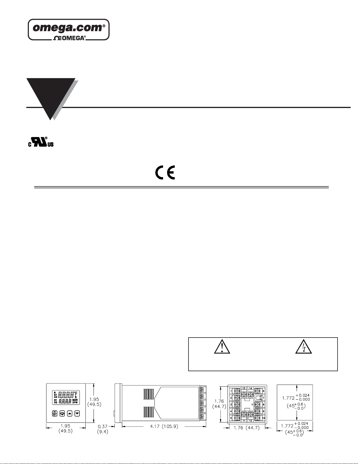
DIMENSIONS In inches (mm)
PANEL CUT-OUT
UL Recognized Component,
File #E123489
CAUTION: Risk of Danger.
Read complete instructions prior to
installation and operation of the unit.
CAUTION: Risk of electric shock.
LP0681X
INSTRUCTION
SHEET
Shop online at: omega.com e-mail: info@omega.com
For latest product manuals: omegamanual.info

OMEGAnet®Online Service
omega.com
Internet e-mail
info@omega.com
Servicing North America:
U.S.A.: One Omega Drive, P.O. Box 4047
ISO 9001 Certified Stamford, CT 06907-0047
TEL: (203) 359-1660 FAX: (203) 359-7700
e-mail: info@omega.com
Canada: 976 Bergar
Laval (Quebec) H7L 5A1, Canada
TEL: (514) 856-6928 FAX: (514) 856-6886
e-mail: info@omega.ca
For immediate technical or application assistance:
U.S.A. and Canada: Sales Service: 1-800-826-6342/1-800-TC-OMEGA
®
Customer Service: 1-800-622-2378/1-800-622-BEST
®
Engineering Service: 1-800-872-9436/1-800-USA-WHEN
®
Mexico: En Español: (001) 203-359-7803 e-mail: espanol@omega.com
FAX: (001) 203-359-7807 info@omega.com.mx
Servicing Europe:
Czech Republic: Frystatska 184, 733 01 Karviná, Czech Republic
TEL: +420 (0)59 6311899 FAX: +420 (0)59 6311114
Toll Free: 0800-1-66342
e-mail: info@omegashop.cz
Germany/Austria: Daimlerstrasse 26, D-75392 Deckenpfronn, Germany
TEL: +49 (0)7056 9398-0 FAX: +49 (0)7056 9398-29
Toll Free in Germany: 0800 639 7678
e-mail: info@omega.de
United Kingdom: One Omega Drive, River Bend Technology Centre
ISO 9002 Certified Northbank, Irlam, Manchester
M44 5BD United Kingdom
TEL: +44 (0)161 777 6611 FAX: +44 (0)161 777 6622
Toll Free in United Kingdom: 0800-488-488
e-mail: sales@omega.co.uk
It is the policy of OMEGA Engineering, Inc. to comply with all worldwide safety and EMC/EMI
regulations that apply. OMEGA is constantly pursuing certification of its products to the European New
Approach Directives. OMEGA will add the CE mark to every appropriate device upon certification.
The information contained in this document is believed to be correct, but OMEGA accepts no liability for any
errors it contains, and reserves the right to alter specifications without notice.
WARNING : These products are not designed for use in, and should not be used for, human applications.
3
INPUT SPECIFICATIONS
1. SENSOR INPUT:
Sample Period: 100 msec (10 Hz rate)
Step Response Time: 300 msec typical, 400 msec max to within 99% of final
value with step input.
Failed Sensor Response:
Main Control Output(s): Programmable preset output
Display: “OPEN”
Alarms: Upscale drive
Analog Output: Upscale drive when assigned to retransmitted input.
Normal Mode Rejection: >40 dB @ 50/60 Hz
Common Mode Rejection: >120 dB, DC to 60 Hz
Overvoltage Protection: 120 VAC @ 15 sec max
2. RTD INPUTS: (CN63200 only)
Type: 2 or 3 wire
Excitation: 150 μA typical
Lead Resistance: 15 Ω max per input lead
Resolution: 1° or 0.1° for all types
3. THERMOCOUPLE INPUTS: (CN63200 only)
Types: T, E, J, K, R, S, B, N, C, and Linear mV
Input Impedance: 20 MΩ for all types
Lead Resistance Effect: 0.25 μV/Ω
Cold Junction Compensation: Less than ±1°C typical (1.5°C max) error
over ambient temperature range.
Resolution: 1° for types R, S, B and 1° or 0.1° for all other types
GENERAL SPECIFICATIONS
1. DISPLAY: 2 Line by 4-digit, LCD negative image transmissive with
backlighting.
Top (Process) Display: 0.3" (7.6 mm) high digits with red backlighting.
Bottom (Parameter) Display: 0.2" (5.1 mm) high digits with green
backlighting.
2. ANNUNCIATORS:
Status Annunciators:
O1 - Main control output is active.
O2 - Cooling output is active (when Alarm 2 is used for cooling).
A1 - Alarm 1 output is active.
A2 - Alarm 2 output is active.
°F, °C - Temperature units.
%PW - Output power percentage is shown in Bottom display.
MAN - Controller is in Manual Mode.
R - Ramping Setpoint indicator.
% - Percent indicator (CN63400 models only).
Display Messages:
OLOL - Measurement exceeds + sensor range
ULUL - Measurement exceeds - sensor range
OPEN - Open sensor is detected (CN63200 only)
SHrt - Shorted sensor is detected (RTD only)
SENS - Measurement exceeds controller limits (CN63400 only)
dddd - Display value exceeds + display range
-ddd - Display value exceeds - display range
3. POWER:
Line Voltage Models:
85 to 250 VAC, 50/60 Hz, 8 VA
Low Voltage Models:
DC Power: 18 to 36 VDC, 4 W
AC Power: 24 VAC, ±10%, 50/60 Hz, 7 VA
4. CONTROLS: Three rubber push buttons for modification and setup of
controller parameters. One additional button (F1) for user programmable
function. One external user input (models with alarms) for parameter lockout
or other user programmable functions.
5. MEMORY: Nonvolatile E
2
PROM retains all programmable parameters.
6. ISOLATION LEVEL:
AC power with respect to all other I/O: 250 V working (2300 V for 1 min.)
Sensor input to analog output: 50 V working (500 V for 1 minute)
Relay contacts to all other I/O: 300 V working (2300 V for 1 minute)
DC power with respect to sensor input and analog output: 50 V working
(500 V for 1 minute)
7. CERTIFICA TIONS AND COMPLIANCES:
SAFETY
UL Recognized Component, File #E123489, UL873, CSA 22.2 No. 24
Recognized to US and Canadian requirements under the Component
Recognition Program of Underwriters Laboratories, Inc.
Type 4X Enclosure rating (Face only), UL50
IEC 61010-1, EN 61010-1: Safety requirements for electrical equipment
for measurement, control, and laboratory use, Part I
IP65 Enclosure rating (Face only), IEC 529
ELECTROMAGNETIC COMPATIBILITY
Notes:
1. Self-recoverable loss of performance during EMI disturbance at 10 V/m:
Measurement input signal may deviate during EMI disturbance.
For operation without loss of performance:
Install one ferrite core one turn to I/O cables at unit.
2. Self-recoverable loss of performance during EMI disturbance at 10 Vrms:
Process and analog output signal may deviate during EMI disturbance.
For operation without loss of performance:
Install one ferrite core one turn to I/O cables and power cable at unit.
Refer to the EMC Installation Guidelines section of this bulletin for
additional information.
8. ENVIRONMENTALCONDITIONS:
Operating Temperature Range: 0 to 50°C
Storage Temperature Range: -40 to 80°C
Operating and Storage Humidity: 85% max relative humidity (non-
condensing) from 0°C to 50°C
Vibration According to IEC 68-2-6: 5 to 150 Hz, in X, Y, Z direction for
1.5 hours, 2 g’s.
Shock According to IEC 68-2-27: Operational 20 g (10 g relay), 11 msec
in 3 directions.
Altitude: Up to 2000 meters
9. CONNECTION: Wire-clamping screw terminals
10. CONSTRUCTION: Black plastic alloy case and collar style panel latch.
Panel latch can be installed for vertical or horizontal instrument stacking.
Black plastic textured bezel with transparent display window. Controller
meets NEMA 4X/IP65 requirements for indoor use when properly installed.
Installation Category II, Pollution Degree 2.
11. WEIGHT: 6.3 oz (179 g)
-200 to +750°C
-328 to +1382°F
N/AN/AN/A
-5.00 mV to
56.00 mV
mV
ASTM
E988-96
No
standard
No
standard
0 to +2315°C
+32 to +4199°F
C
W5/W6
ITS-90
(+) Orange
(-) Blue
(+) Orange
(-) Red
-200 to +1300°C
-328 to +2372°F
N
ITS-90
No
standard
No
standard
+149 to +1820°C
+300 to +3308°F
B
ITS-90
(+) White
(-) Blue
No
standard
0 to +1768°C
+32 to +3214°F
S
ITS-90
(+) White
(-) Blue
No
standard
0 to +1768°C
+32 to +3214°F
R
ITS-90
(+) Brown
(-) Blue
(+) Yellow
(-) Red
-200 to +1250°C
-328 to +2282°F
K
ITS-90
(+) Yellow
(-) Blue
(+) White
(-) Red
-200 to +760°C
-328 to +1400°F
J
ITS-90
(+) Brown
(-) Blue
(+) Violet
(-) Red
E
ITS-90
(+) White
(-) Blue
(+) Blue
(-) Red
-200 to +400°C
-328 to +752°F
T
BS 1843ANSI
STANDARD
WIRE COLOR
DISPLAYRANGETYPE
TYPE INPUT TYPE RANGE STANDARD
385
100 Ω platinum,
Alpha = .00385
-200 to +600°C
-328 to +1112°F
IEC 751
392
100 Ω platinum,
Alpha = .003919
-200 to +600°C
-328 to +1112°F
No official
standard
672
120 Ω nickel,
Alpha = .00672
-80 to +215°C
-112 to +419°F
No official
standard
Ohms Linear Resistance
0.0 to 320.0 Ω
N/A
Emissions to EN 50081-2
Enclosure class AEN 55011RF interference
150 KHz - 80 MHz
Level 3; 10 V/rms
2
EN 61000-4-6RF conducted interference
Level 3; 2 kV power
Level 4; 2 kV I/OEN 61000-4-4Fast transients (burst)
80 MHz - 1 GHz
Level 3; 10 V/m
1
EN 61000-4-3Electromagnetic RF fields
Level 2; 4 kV contact
Level 3; 8 kV air
EN 61000-4-2Electrostatic discharge
Immunity to EN 50082-2
Power mains class A
4
EMC INSTALLATION GUIDELINES
Although this controller is designed with a high degree of immunity to
Electromagnetic Interference (EMI), proper installation and wiring methods
must be followed to ensure electromagnetic compatibility (EMC) in each
application. The type of the electrical noise, source or coupling method into the
controller may be different for various installations. The controller becomes
more immune to EMI with fewer I/O connections. Cable length, routing, and
shield termination are very important and can mean the difference between a
successful or troublesome installation. Listed are some EMC guidelines for
successful installation in an industrial environment.
1. The controller should be mounted in a metal enclosure that is properly
connected to protective earth.
2. Use shielded (screened) cables for all Signal and Control inputs. The shield
(screen) pigtail connection should be made as short as possible. The
connection point for the shield depends somewhat upon the application.
Listed below are the recommended methods of connecting the shield, in order
of their effectiveness.
a. Connect the shield only at the panel where the controller is mounted to
earth ground (protective earth).
b. Connect the shield to earth ground at both ends of the cable, usually when
the noise source frequency is more than 1 MHz.
c. Connect the shield to common of the controller and leave the other end of
the shield unconnected and insulated from earth ground.
3. Never run Signal or Control cables in the same conduit or raceway with AC
power lines, conductors feeding motors, solenoids, SCR controls, and
heaters, etc. The cables should be run through metal conduit that is properly
grounded. This is especially useful in applications where cable runs are long
and portable two-way radios are used in close proximity or if the installation
is near a commercial radio transmitter.
4. Signal or Control cables within an enclosure should be routed as far away as
possible from contactors, control relays, transformers, and other noisy
components.
5. In extremely high EMI environments, the use of external EMI suppression
devices, such as ferrite suppression cores, is effective. Install them on Signal
and Control cables as close to the controller as possible. Loop the cable
through the core several times or use multiple cores on each cable for
additional protection. Install line filters on the power input cable to the
controller to suppress power line interference. Install them near the power
entry point of the enclosure. The following EMI suppression devices (or
equivalent) are recommended:
Ferrite Suppression Cores for Signal and Control cables:
Fair-Rite # 0443167251
TDK # ZCAT3035-1330A
Steward # 28B2029-0A0
Line Filters for input power cables:
Schaffner # FN610-1/07
Schaffner # FN670-1.8/07
Corcom # 1 VR3
Note: Reference manufacturer’s instructions when installing a line filter.
6. Long cable runs are more susceptible to EMI pickup than short cable runs.
Therefore, keep cable runs as short as possible.
7. Switching of inductive loads produces high EMI. Use of snubbers across
inductive loads suppresses EMI.
OUTPUT SPECIFICATIONS
1. CONTROLAND ALARM OUTPUTS:
Relay Output:
Type: Form A
Contact Rating: 3 A @ 250 VAC or 30 VDC; 1/10 HP @ 120 VAC
(inductive load)
Life Expectancy: 100,000 cycles at max. load rating
(Decreasing load and/or increasing cycle time, increases life expectancy)
Logic/SSR Output (main control output only):
Rating: 45 mA max @ 4 V min., 7 V nominal
2. MAIN CONTROL:
Control: PID or On/Off
Output: Time proportioning or DC Analog
Cycle Time: Programmable
Auto-Tune: When selected, sets proportional band, integral time, derivative
time, and output dampening time. Also sets input filter and (if applicable)
cooling gain.
Probe Break Action: Programmable
3. ALARMS: (optional) 2 relay alarm outputs.
Modes:
None
Absolute High Acting (Balanced or Unbalanced Hysteresis)
Absolute Low Acting (Balanced or Unbalanced Hysteresis)
Deviation High Acting
Deviation Low Acting
Inside Band Acting
Outside Band Acting
Heat (Alarm 1 on Analog Output models only)
Cool (Alarm 2)
Reset Action: Programmable; automatic or latched
Standby Mode: Programmable; enable or disable
Hysteresis: Programmable
Sensor Fail Response: Upscale
Annunciator: “A1” and “A2” programmable for normal or reverse acting
4. COOLING: Software selectable (overrides Alarm 2).
Control: PID or On/Off
Output: Time proportioning
Cycle Time: Programmable
Proportional Gain Adjust: Programmable
Heat/Cool Deadband Overlap: Programmable
5. ANALOG DC OUTPUT: (optional)
Action: Control or retransmission
Update Rate: 0.1 to 250 sec
* Accuracies are expressed as ± percentages over 0 to 50 °C ambient range
after 20 minute warm-up.
** Outputs are independently jumper selectable for either 10 Vor 20 mA. The
output range may be field calibrated to yield approximately 5% overrange
and a small underrange (negative) signal.
OUTPUT
RANGE **
ACCURACY * COMPLIANCE RESOLUTION
0 to 10 V
0.3% of FS
+ ½ LSD
10 kΩ min
1/8000
0 to 20 mA
0.3% of FS
+ ½ LSD
500 Ω max
1/8000
4 to 20 mA
0.3% of FS
+ ½ LSD
500 Ω max
1/6400
INPUT SPECIFICATIONS (Cont’d)
4. SIGNAL INPUT: (CN63400 only)
* Accuracies are expressed as ± percentages over 0 to 50 °C ambient range
after 20 minute warm-up.
5. TEMPERATURE INDICATION ACCURACY: (CN63200 only)
± (0.3% of span, +1°C) at 23 °C ambient after 20 minute warm up. Includes
NIST conformity, cold junction effect, A/D conversion errors and
linearization conformity.
Span Drift (maximum): 130 PPM/°C
6. USER INPUT: (Only controllers with alarms have a user input terminal.)
Internally pulled up to +7 VDC (100 KΩ), V
IN MAX
= 35 V, VIL= 0.6 V max,
VIH= 1.5 V min, I
OFF
= 40 μA max
Response Time: 120 msec max
Functions: Programmable
INPUT RANGE ACCURACY * IMPEDANCE RESOLUTION
10 VDC
(-1 to 11)
1 MΩ
50 V 10 mV
20 mA DC
(-2 to 22)
10 Ω
100 mA 10 µA
MAX
CONTINUOUS
OVERLOAD
0.30 % of
reading
+0.03V
0.30 % of
reading
+0.04mA
5
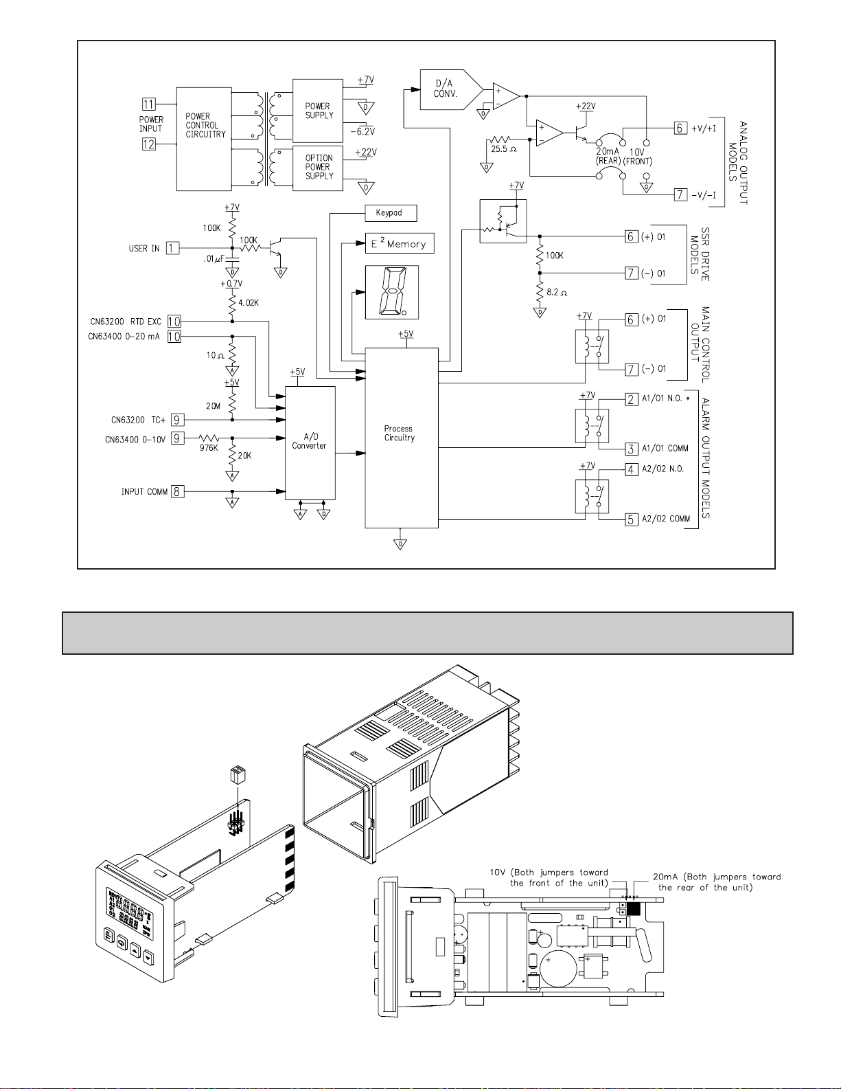
BLOCK DIAGRAM
*A1 becomes main control O1, if selected for heating in the
analog out models.
1.0 S
ETTING THE JUMPERS
(ANALOG O
UTPUT MODELS ONLY)
To insure proper operation, the Analog Output jumpers must be set to the
same range selected in programming Module 2-OP. The default jumper
setting is for 20 mA. The default setting in Module 2-OP is 4-20
mA. To access the jumpers, insert a flat-blade screwdriver
between the front panel and the side case slot. This should
disengage the top and bottom front panel latches
from the case grooves. Pull the front panel assembly
with the controller boards out of the
case. The jumpers are located
inside the controller on the left
board along the back top section.
VIEW FROM TOP OF UNIT
6
3.0 WIRING THE CONTROLLER
WIRING CONNECTIONS
All wiring connections are made to the rear screw terminals. When wiring the
controller, use the numbers on the label and those embossed on the back of the
case, to identify the position number with the proper function.
All conductors should meet voltage and current ratings for each terminal.
Also, cabling should conform to appropriate standards of good installation, local
codes and regulations. It is recommended that power (AC or DC) supplied to the
controller be protected by a fuse or circuit breaker. Strip the wire, leaving
approximately 1/4" (6 mm) bare wire exposed (stranded wires should be tinned
with solder). Insert the wire under the clamping washer and tighten the screw
until the wire is clamped tightly.
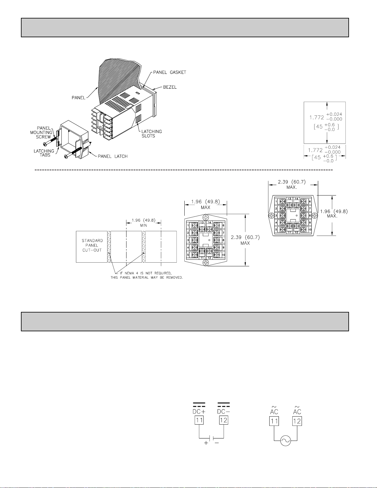
CONTROLLER POWER CONNECTIONS
For best results, the power should be relatively “clean” and within
the specified limits. Drawing power from heavily loaded circuits or
from circuits that also power loads that cycle on and off should be
avoided. It is recommended that power supplied to the controller be
protected by a fuse or circuit breaker.
VDC
VAC
2.0 INSTALLING THE CONTROLLER
The CN63200 and CN63400 controllers meet NEMA 4X/IP65 requirements
for indoor use to provide a watertight seal in steel panels with a minimum
thickness of 0.09", or aluminum panels
with a minimum thickness of 0.12".
The controllers are designed to be
mounted into an enclosed panel.
The bezel assembly must be in
place during installation of
the controller.
Instructions:
1. Prepare the panel cutout to the proper dimensions.
2. Remove the panel latch from the controller. Discard the cardboard sleeve.
3. Carefully remove the center section of the panel gasket and discard. Slide the
panel gasket over the rear of the controller, seating it against the lip at the
front of the case.
4. Insert the controller into the panel cutout. While holding the controller in
place, push the panel latch over the rear of the controller, engaging the tabs
of the panel latch in the farthest forward slot possible.
5. To achieve a proper seal, tighten the panel latch screws evenly until the
controller is snug in the panel, torquing the screws
to approximately 7 in-lb (79 N-cm).
Overtightening can result in distortion of the
controller, and reduce the effectiveness of the seal.
Note: The installation location of the controller is
important. Be sure to keep it away from heat
sources (ovens, furnaces, etc.) and away from
direct contact with caustic vapors, oils, steam, or
any other process by-products in which exposure
may affect proper operation.
Multiple Controller Stacking
The controller is designed to allow for close spacing of multiple controllers
in applications that do not require protection to NEMA 4X. Controllers can be
stacked either horizontally or vertically. For vertical stacking, install the panel
latch with the screws to the sides of the controller. For horizontal stacking, the
panel latch screws should be at the top and bottom of the controller. The
minimum spacing from centerline to centerline of controllers is 1.96" (49.8
mm). This spacing is the same for vertical or
horizontal stacking.
Note: When stacking
controllers, provide
adequate panel
ventilation to ensure
that the maximum
operating temperature
range is not exceeded.
7
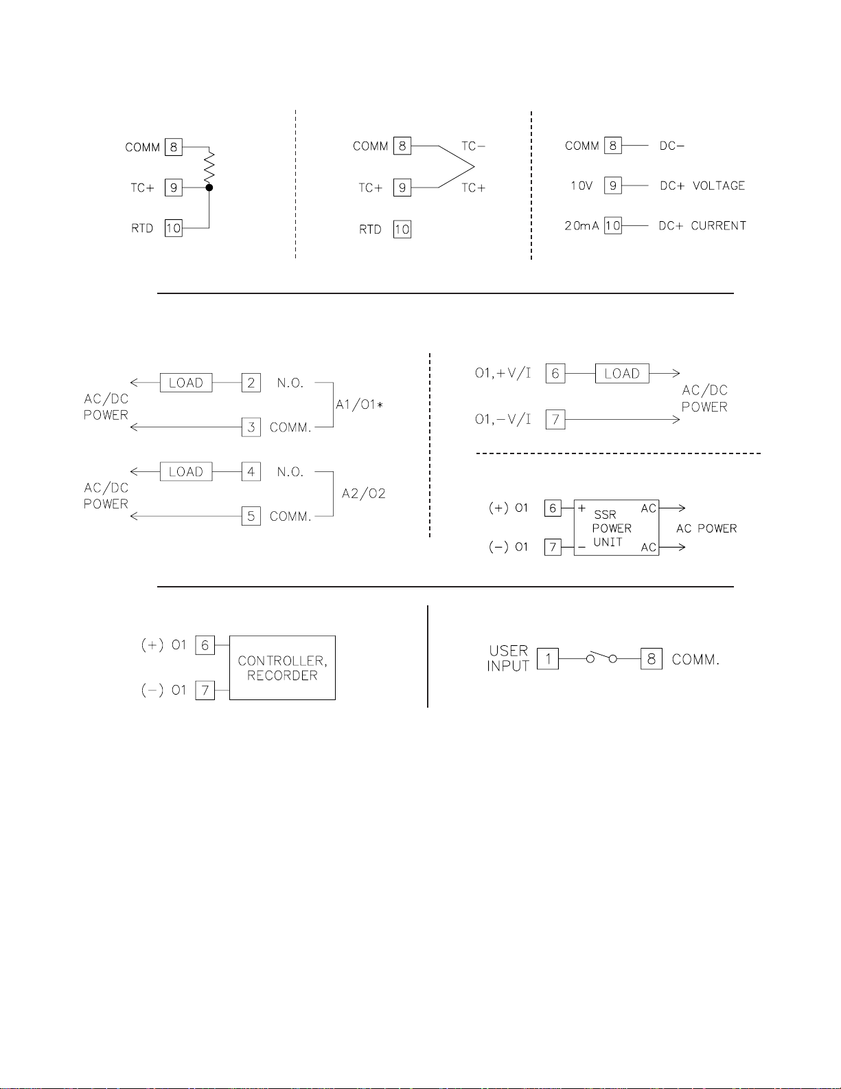
INPUT CONNECTIONS
For two wire RTDs, install a copper sense lead of the same gauge and length
as the RTD leads. Attach one end of the wire at the probe and the other end to
input common terminal. Complete lead wire compensation is obtained. This is
the preferred method. If a sense wire is not used, then use a jumper. A
temperature offset error will exist. The error may be compensated by
programming a temperature offset.
CONTROL AND ALARM OUTPUT CONNECTIONS
RTD and Resistance Thermocouple and Millivolt
Voltage and Current
Alarm Models Main Control Relay Models
Main Control Logic/SSR Models
ANALOG DC OUTPUT CONNECTIONS
USER INPUT CONNECTIONS
*A1 becomes main control O1, if selected for
heating in the analog out models.
8
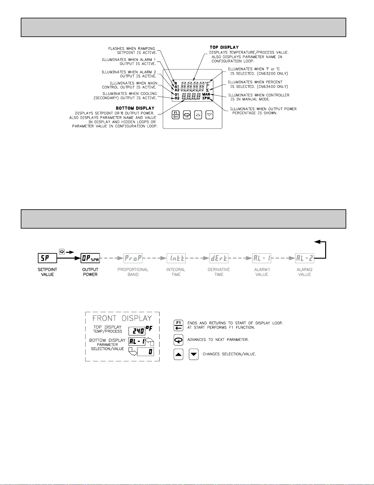
FRONT PANEL KEYS
The F1 key is pressed to exit (or escape) directly to the start of the
Display Loop. While in the Display Loop, the F1 key can be pressed to
activate its programmed function.
The Loop key is pressed to advance to the next parameter, to activate
a changed selection/value, and when held for three seconds, enter the
Hidden Loop.
The Arrow keys are used to scroll through parameter
selections/values and in the Configuration Loop they are used to
scroll to the appropriate Parameter Module.
4.0 REVIEWING THE FRONT KEYS AND DISPLAY
5.0 PROGRAMMING: DISPLAY LOOP
DISPLAY LOOP
Note: Setpoint and Output Power are the only parameters visible in the Display Loop with Factory Settings. The remaining parameters can
be selected for the Display Loop within Module 3.
Parameter availability is model and programming dependent.
DISPLAY LOOP
At power up, all display segments light, and then the programmed input type
and the controller’s software version will flash. Then the Temperature/Process
Value is shown in the top display, and the Setpoint Value is shown in the bottom
display. This is the Display Loop. If the Setpoint is hidden or locked, the Display
Loop will default to Output Power. If Output Power is also hidden or locked out,
the bottom display is blank. During programming, the F1 key can be pressed to
return the controller to this point. (Only in the Display Loop will the F1 key
perform the user function programmed in Input Module .)
When the is pressed the controller advances to the next parameter in the
Display Loop. Except for Setpoint and % Output Power, the bottom display
alternates between the parameter name and its selection/value. The arrow keys
are pressed to change the selection/value for the shown parameter. The new
selection/value is activated when the is pressed. Display Loop parameters
may be locked out or hidden in Lockout Module . Some parameters are
model and programming dependent.

9
SETPOINT VALUE (SP1) *
SETPOINT VALUE (SP2) *
-999 to 9999
0.0
OP
2.0
SP
% OUTPUT POWER *
-100 to 100.0
-999
to 9999
Typically, the controller is operating with the Setpoint value in the bottom
display. There is no annunciator nor parameter indication for Setpoint in the
Display Loop. The parameter name alternates with the setpoint value in the
Hidden Loop. The Setpoint value can be changed, activated and stored by
pressing the arrow keys. This is the only parameter that can be configured as
read only in the Display Loop, but read/write in the Hidden Loop. It is possible
to store a second Setpoint value that can be selected in the Hidden Loop, by the
F1 key or the user input. Both Setpoint values are limited by the Setpoint Low
and High Limits in Input Module .
The % Output Power is shown with the %PW annunciator. The parameter
name alternates with the % Output Power value in the Hidden Loop. While the
controller is in Automatic Mode, this value is read only. When the controller is
placed in Manual Mode, the value can be changed, activated and stored by
pressing the arrow keys. For more details on % Output Power, see Control
Mode Explanations.
ª
«
120
Intt
INTEGRAL TIME
0 to 9999 seconds
Integral action shifts the center point position of the proportional band to
eliminate error in the steady state. The higher the integral time, the slower the
response. The optimal integral time is best determined during PID Tuning. If
time is set to zero, the previous Integral output power value is maintained.
Offset Power can be used to provide Manual Reset.
ª
«
30
dErt
DERIVATIVE TIME
0 to 9999 seconds per repeat
Derivative time helps to stabilize the response, but too high of a derivative
time, coupled with noisy signal processes, may cause the output to fluctuate too
greatly, yielding poor control. Setting the time to zero disables derivative action.
ALARM 1 VALUE
-999 to 9999
On models with alarms, the value for Alarm 1 can be entered here. The value
is either absolute (absolute alarm types) or relative to the Setpoint value
(deviation and band alarm types.) When Alarm 1 is programmed for HEAt or
NonE, this parameter is not available. For more details on alarms, see Alarm
Module "-.
ª
«
0.0
OPOF
OUTPUT POWER OFFSET
When the Integral Time is set to zero and the controller is in the Automatic
Mode, this parameter will appear after % Output Power. It is also shown with
the %PW annunciator illuminated. The power offset is used to shift the
proportional band to compensate for errors in the steady state. If Integral Action
is later invoked, the controller will re-calculate the internal integral value to
provide “bumpless” transfer and Output Power Offset will not be necessary.
ª
«
4.0
ProP
PROPORTIONAL BAND
0.0 to 999.9
(% of full input range)
The proportional band should be set to obtain the best response to a process
disturbance while minimizing overshoot. A proportional band of 0.0% forces
the controller into On/Off Control with its characteristic cycling at Setpoint. For
more information, see Control Mode and PID Tuning Explanations.
* Alternating indication only used in the Hidden Loop.
ALARM 2 VALUE
-999 to 9999
On models with alarms, the value for Alarm 2 can be entered here. The value
is either absolute (absolute alarm types) or relative to the Setpoint value
(deviation and band alarm types.) When Alarm 2 is programmed for CooL or
NonE, this parameter is not available. For more details on alarms, see the Alarm
Module 4-AL.
The values shown for the displays are the factory settings.
CN63200
CN63400
ª
«
0
0.0
AL-1
CN63200
CN63400
ª
«
0
0.0
AL-2
CN63200
CN63400
0
0.0
SP
CN63200
CN63400
-100 to 100.0
 Loading...