

Omega Products CN63100 Installation Manual
omega.com
e-mail: info@omega.com
User’s Guide
Shop online at
CCNN6633110000//CCNN6633330000
SSeerriieess
1/16 DDIN
Temperature/Process
Controllers
UL Recognized Component,
File # E123489
LP0679X

OMEGAnet®Online Service
omega.com
Internet e-mail
info@omega.com
Servicing North America:
U.S.A.: ISO 9001 Certified Canada:
One Omega Drive, P.O. Box 4047 976 Bergar
Stamford, CT 06907-0047 Laval (Quebec) H7L 5A1, Canada
TEL: (203) 359-1660 FAX: (203) 359-7700 TEL: (514) 856-6928 FAX: (514) 856-6886
e-mail: info@omega.com e-mail: info@omega.ca
For immediate technical or application assistance:
U.S.A. and Canada: Mexico:
Sales Service: 1-800-826-6342/1-800-TC-OMEGA
®
En Español: (001) 203-359-7803
Customer Service: 1-800-622-2378/1-800-622-BEST
®
FAX: (001) 203-359-7807
Engineering Service: 1-800-872-9436/1-800-USA-WHEN®e-mail: espanol@omega.com info@omega.com.mx
Servicing Europe:
Czech Republic: Germany/Austria:
Frystatska 184, 733 01 Karviná, Czech Republic Daimlerstrasse 26, D-75392 Deckenpfronn, Germany
TEL: +420 (0)59 6311899 FAX: +420 (0)59 6311114 TEL: +49 (0)7056 9398-0 FAX: +49 (0)7056 9398-29
Toll Free: 0800-1-66342 e-mail: info@omegashop.cz Toll Free in Germany: 0800 639 7678 e-mail: info@omega.de
United Kingdom: One Omega Drive, River Bend Technology Centre
ISO 9002 Certified Northbank, Irlam, Manchester M44 5BD United Kingdom
TEL: +44 (0)161 777 6611 FAX: +44 (0)161 777 6622
Toll Free in United Kingdom: 0800-488-488 e-mail: sales@omega.co.uk
It is the policy of OMEGA Engineering, Inc. to comply with all worldwide safety and EMC/EMI regulations that apply. OMEGA is constantly pursuing
certification of its products to the European New Approach Directives. OMEGA will add the CE mark to every appropriate device upon certification.
The information contained in this document is believed to be correct, but OMEGA accepts no liability for any errors it contains, and reserves the
right to alter specifications without notice.
WARNING : These products are not designed for use in, and should not be used for, human applications.

Table of Contents
GENERAL DESCRIPTION····························································· 1
SafetySummary ·································································· 1
INSTALLATION DESCRIPTION ······················································· 2
Instructions:······································································ 2
MultipleUnitStacking······························································ 3
Unit Removal Procedure···························································· 3
RemovingBezelAssembly·························································· 3
Installing Bezel Assembly··························································· 3
CONNECTIONDESCRIPTION ························································· 4
EMCInstallationGuidelines························································· 4
Wiring Connections ································································ 5
Signal Wiring ····································································· 5
Thermocouple (CN63100)························································ 5
RTD (CN63100) ································································ 5
Signal (CN63300) ······························································ 6
PowerWiring····································································· 6
ControlandAlarmOutputs·························································· 6
Relay Connections ····························································· 6
Logic/SSR Connections (CN63100 only) ············································ 7
RemoteSetpointWiring···························································· 7
Main Linear DC Output Wiring ······················································· 7
Second Linear DC Output Wiring····················································· 7
User Input Wiring ································································· 7
RearTerminalAssignments························································· 8
CN63100 Models Without RS-485 and Analog Output ································· 8
CN63100 Models With RS-485 or Linear DC Analog Output ···························· 8
············································································· 8
ALL CN63300 Models ··························································· 9
Serial Connections to a Host Terminal ··············································· 10
Linear DC Analog Output Jumper Selection ··········································· 11
FRONTPANELDESCRIPTION ······················································· 12
ButtonFunctions································································· 12
INITIALCONFIGURATIONSTART-UP ················································· 13
-i-

ControllerPower-up ······························································ 13
ParameterConfigurationOverview·················································· 13
ParameterConfigurationBasicStart-up·············································· 13
ParameterConfigurationforSerialStart-up··········································· 13
ControlStart-up·································································· 13
ValidControlModeCombinations··················································· 14
Front Panel Programming Chart For CN63100 & CN63300 Controllers ···················· 15
NORMALDISPLAYMODE··························································· 16
FRONTPANELPROGRAMDISABLE·················································· 16
UNPROTECTEDPARAMETERMODE ················································· 17
PROTECTEDPARAMETERMODE···················································· 18
HIDDEN FUNCTION MODE ·························································· 19
CONFIGURATION PARAMETERMODE················································ 19
REFERENCETABLES:CONFIGURATIONPARAMETERMODULES························ 20
Configure Module 1 - Input Parameters (1-IN) CN63100································· 20
Configure Module 1 - Input Parameters (1-IN) CN63300································· 21
Configure Module 2 - Output Parameters (2-OP) ······································· 22
Configure Module 3 - Lockout Parameters (3-LC) ······································ 23
Configure Module 4 - Alarm Parameters (4-AL) ········································ 24
Configure Module 5 - Cooling Parameters (5-O2) ······································ 25
Configure Module 6 - Serial Communications (6-SC) ··································· 26
Configure Module 7 - Remote Setpoint Parameters (7-rS or 7-n2) ························· 27
Configure Module 8 - Second Linear DC Analog Output (8-A2) ····························· 27
Configure Module 9 - Factory Service Operations (9-FS) ································ 27
USERPARAMETERVALUECHART··················································· 28
CONFIGURATION PARAMETER EXPLANATIONS ······································· 30
Input Parameter Module (1- IN) CN63100 Models ······································ 30
Input Type (tYPE) ····························································· 30
TemperatureScale(SCAL) ····················································· 30
TemperatureResolution(dCPt)·················································· 30
Digital Input Filtering and Display Update Rate (FLtr) ································ 30
Input Sensor Correction Constant (SHFt) ·········································· 30
SetpointLimitValues(SPLO&SPHI)············································· 30
-ii-

SetpointRampRate(SPrP)····················································· 31
User Input (InPt) ······························································ 31
Input Parameter Module (1- In) CN63300 models ······································ 32
Input Type (tYPE) ····························································· 32
DecimalPointPosition(dCPt) ··················································· 32
Rounding Increment ( rnd) ······················································ 32
Digital Input Filtering and Display Update Rate (FLtr) ································ 32
ScalingPoints································································ 32
DisplayValues(dSP1&dSP2) ·················································· 33
Signal Input Values (INP1 & INP2) ··············································· 33
SetpointLimitValues(SPLO&SPHI)············································· 33
SetpointRampRate(SPrP)····················································· 33
User Input (InPt) ······························································ 34
Output Parameter Module (2-OP) ··················································· 35
Time Proportioning Cycle Time (CYCt) ············································ 35
OutputControlAction(OPAC)··················································· 35
OutputPowerLimits(OPLO&OPHI) ············································· 35
Sensor Fail Power Level (OPFL) CN63100 only···································· 35
Output Power Dampening Filtering Time (OPdP) ···································· 35
ON/OFFControlHysteresis(CHYS) ·············································· 36
Auto-TuneCode(tcod)························································· 36
Main Linear DC Output Range (ANtP) (Optional) ···································· 36
Main Linear DC Output Source (ANAS) (Optional) ··································· 36
Main Linear DC Update Time (ANUt) (Optional) ····································· 36
Main Linear DC Output Scaling Points (ANLO, ANHl) (Optional) ······················· 36
Lockouts Parameter Module (3-LC)·················································· 37
Lower DisplayLockouts(SP,OP,dEv,UdSP andbdSP) ····························· 37
ProtectedModeLockouts(CodE,PId,andAL) ····································· 37
Hidden Mode Lockouts (ALrS, SPSL, trnF, and tUNE ) ······························· 37
Alarm Parameter Module (4-AL) (Optional)············································ 38
AlarmAction(Act1,Act2)······················································· 38
AlarmActionFigures··························································· 39
AlarmReset(rSt1,rSt2)························································ 41
Alarm Standby Delay (Stb1, Stb2) ················································ 41
-iii-

AlarmValue(AL-1,AL-2) ······················································· 41
AlarmHysteresis (AHYS)······················································· 41
Cooling Parameters Module (5-02) (Optional) ········································· 42
CoolingOutputCycleTime(CYC2)··············································· 42
CoolingRelativeGain(GAn2) ··················································· 42
Heat and Cool Overlap/Deadband (db-2) ·········································· 42
Serial Communications Module (6-SC) (Optional) ······································ 43
BaudRate(bAUd)····························································· 43
CharacterFrameFormat(ConF)················································· 43
ControllerAddressNumber(Addr) ··············································· 43
AbbreviatedorFull Transmission(Abrv)··········································· 43
PrintOptions(PoPt) ··························································· 43
Remote Setpoint Parameters Module (7-n2 or 7-rS) (Optional) ···························· 44
RemoteSetpointDisplayValues(dSP1anddSP2)·································· 44
Remote Setpoint Signal Input Values (INP1 and INP2) ······························· 44
RemoteSetpointFiltering(Fltr andbANd) ········································· 44
Remote/LocalSetpointTransferOptions(trnF) ····································· 44
Second Linear DC Analog Output Module (8-A2) (Optional) ······························ 45
Second Linear DC Output Range (A2tP) ··········································· 45
Second Linear DC Output Scaling Points (A2LO, A2Hl) ······························ 45
Factory Service Operations Module (9-FS)············································ 45
MANUALCONTROL ································································ 46
ON/OFFCONTROL································································· 47
AUTO-TUNE FORPIDCONTROL····················································· 50
InitiateAuto-Tune ································································ 51
Auto-TuneOfHeat/CoolSystems ··················································· 51
Auto-TuneOfCascadeControl ····················································· 51
PID CONTROL EXPLANATIONS ······················································ 52
Proportional Band ································································ 52
IntegralTime···································································· 52
DerivativeTime·································································· 53
Output Power Offset (Manual Reset)················································· 53
PIDAdjustments································································· 53
MANUALTUNINGFORPIDCONTROL ················································ 55
-iv-

REMOTESETPOINTOPTION ························································ 56
CASCADECONTROL ······························································· 56
SERIALCOMMUNICATIONS INTERFACE·············································· 57
RS-485SerialCommunications····················································· 57
ControllerConfiguration··························································· 57
Sending Commands And Data ······················································ 57
Sending Numeric Data ···························································· 57
Controller (Node) Address ························································· 57
Commands Table ································································ 57
Register Identification Table························································ 58
TerminatorTable································································· 58
ExamplesofCommandStrings:····················································· 58
Command Code Explanations ······················································ 58
Controller (Node) Address: N ···················································· 58
Read Register Command Code: T ················································ 59
Write Register Command Code: V ················································ 59
Reset Alarm Command Code: R ················································· 59
Control Action Command Code: C ················································ 59
Block Read Register Command Code: P··········································· 59
Terminator:*or$····························································· 59
BlockReadCommandByteTable··················································· 60
Unique Register Explanations ······················································ 61
SetpointRampUsingAutomatic SetpointRampingRegister:K························ 61
SetpointRampUsingPeriodicSetpointWriteRegister:B····························· 61
Periodic Setpoint Write Commands (E
2
PROM precautions)··························· 61
OutputStatus: W······························································ 61
CommunicationFormat···························································· 61
Command Response Time ························································· 62
FullField ControllerTransmissionByteFormat········································ 63
AbbreviatedControllerTransmissionByteFormat······································ 64
Troubleshooting Serial Communications·············································· 64
APPLICATIONEXAMPLES ·························································· 65
CN63100 OEM Paint Sprayer Application ············································ 65
CN63300 Water Processing Application ·············································· 66
-v-

CHECKSANDCALIBRATION ························································ 67
Main Input Check ································································ 67
mV Reading Check (CN63100) ·················································· 67
Thermocouple Cold Junction Temperature Check (CN63100) ························· 67
RTD Ohms Reading Check (CN63100) ············································ 67
Voltage Check (CN63300) ······················································ 67
Current Check (CN63300) ······················································ 67
Remote Setpoint Input Check (CN63100 and CN63300) ································· 67
ErrorFlagE-CL·································································· 67
Calibration For CN63100 ·························································· 68
FactoryServiceOperations-Calibration(9-FS)····································· 68
Millivolt Calibration (CAL) ······················································· 68
Thermocouple Cold Junction Calibration (CJC) ····································· 69
RTDOhmsCalibration(rtd) ····················································· 69
Main or Second Linear DC Analog Output Calibration ································ 69
RemoteSetpointCalibration····················································· 69
Calibration For CN63300 ·························································· 70
FactoryServiceOperations(9-FS) ··············································· 70
Input Calibration ······························································ 70
Main or Second Linear DC Analog Output Calibration ································ 70
RemoteSetpointCalibration····················································· 70
TROUBLESHOOTING······························································· 71
REPLACEABLEOUTPUTBOARDDESCRIPTION ······································· 73
SPECIFICATIONS AND DIMENSIONS ············································· 74
CN63100 TEMPERATURE CONTROLLER PART NUMBERS ·························· 78
CN63300 PROCESS CONTROLLER PART NUMBERS ································ 79
-vi-
GENERAL DESCRIPTION
The CN63100 Controller accepts signals from a variety of temperature
sensors (thermocouple or RTD elements), while the CN63300 Controller
accepts either a 0 to 10 VDC or 0/4 to 20 mA DC input signal. Both controllers
precisely display the process, and provide an accurate output control signal
(time proportional or linear DC) to maintain a process at the desired control
point. The controllers’ comprehensive programming allows them to meet a
wide variety o f application requirements.
The controller can operate in the PID control mode for both heating and
cooling, with on-demand Auto-Tune, which will establish the tuning
constants. The PID tuning constants may be fine-tuned by the operator at any
time and then locked out from further modification. The controller employs a
unique overshoot suppression feature, which allows the quickest response
without excessive overshoot. Operation of the controller can be transferred to
manual mode, providing the operator with direct control of the output. The
controller may also be programmed to operate in the ON/OFF control mode
with adjustable hysteresis.
Dual 4-digit displays allow viewing of the process/temperature and
setpoint simultaneously. Front panel indicators inform the operator of the
controller and output status. The control output and the alarm outputs are
field replaceable on select models.
Optional alarm (s) can be configured to activate according to a variety of
actions (Absolute HI or LO, Deviation HI or LO, Band IN or OUT, and Heater
Current Break) with adjustable hysteresis. A standby feature suppresses the
alarm during power-up until the process stabilizes outside the alarm region.
Optional Main Linear DC output (10 V and 20 mA) can be used for control or
retransmission purposes. Programmable output update time reduces valve or
actuator activity. The output range can be scaled independent of the input range.
Optional Second Linear DC output (10 V or 20 mA) provides an
independent process retransmission, while the main Linear DC output is
being used for control. The output range can be scaled independent of the
input range.
A Remote Setpoint input (0/4 to 20 mA) allows for cascade control loops,
where tighter control quality is required; and allows for remotely driven
setpoint signal from computers or other similar equipment. Straightforward
end point scaling with independent filtering and local/remote transfer option
expands the controller’s flexibility.
The optional RS485 serial communication interface provides two-way
communication between a controller and o ther compatible equipment such as
a printer, PLC, HMI, or a host computer. In multipoint applications (up to
thirty-two), the address number of each controller on the line can be
programmed from 0 to 99. Data from the controller can be interrogated or
changed, and alarm output(s) may be reset by sending the proper command
code via serial communications.
The unit is constructed of a lightweight, high impact plastic case with a tinted
front panel. The front panel meets NEMA 4X/IP65 specifications when properly
installed. Multiple units can be stacked horizontally or vertically. Modern
surface-mount technology, extensive testing, plus high immunity to noise
interference makes the controller extremelyreliableinindustrialenvironments.
SAFETY SUMMARY
All safety related regulations, local codes and instructions that appear in
the manual or on equipment must be observed to ensure personal safety and to
prevent damage to either the instrument or equipment connected to it. If
equipment is used in a manner not specified by the manufacturer, the
protection provided by the equipment may be impaired.
Do not use the controller to directly command motors, v alves, or other
actuators not equipped with safeguards. To do so, can be potentially harmful
to persons or equipment in the event of a fault to the unit. An independent and
redundant temperature limit indicator with alarm outputs is strongly
recommended.
CAUTION: Risk of Danger.
Read complete instructions prior to
installation and operation of the unit.
CAUTION: Risk of electric shock.
-1-

INSTALLATION DESCRIPTION
The controller meets NEMA 4X/IP65 requirements for
indoor use to provide a watertight seal in steel panels with a
minimum thickness of 0.09 inch, or aluminum panels with
a minimum thickness of 0.12 inch. The units are intended to
be mounted into an enclosed panel. It is designed so that the
units can be stacked horizontally or vertically (see Figure
1). The bezel assembly MUST be in place during
installation of the unit.
INSTRUCTIONS:
1. Prepare the panel cutout to the dimensions shown in
Figure 1, Panel Installation.
2. Remove the panel latch from the unit. Discard the
cardboard sleeve.
3. Carefully remove the center section of the panel gasket
and discard. Slide the panel gasket over the unit from the
rear, seating it against the lip at the front of the case.
4. Insert the unit into the panel cutout. While holding the
unit in place, push the panel latch over the rear of the
unit, engaging the tabs of the panel latch in the farthest
forward slot possible.
5. To achieve a proper seal, tighten the panel latch screws
evenly until the unit is snug in the panel, torquing the
screws to approximately 7 in-lbs (79 N-cm). Over
tightening can result in distortion of the panel, and
reduce the effectiveness of the seal.
Note: The installation location of the controller is important.
Be sure to keep it away from heat sources (ovens, furnaces,
etc.), and away from direct contact with caustic vapors,
oils, steam, or any other process byproducts in which
exposure may affect proper operation.
-2-
Figure 1, Panel Installation
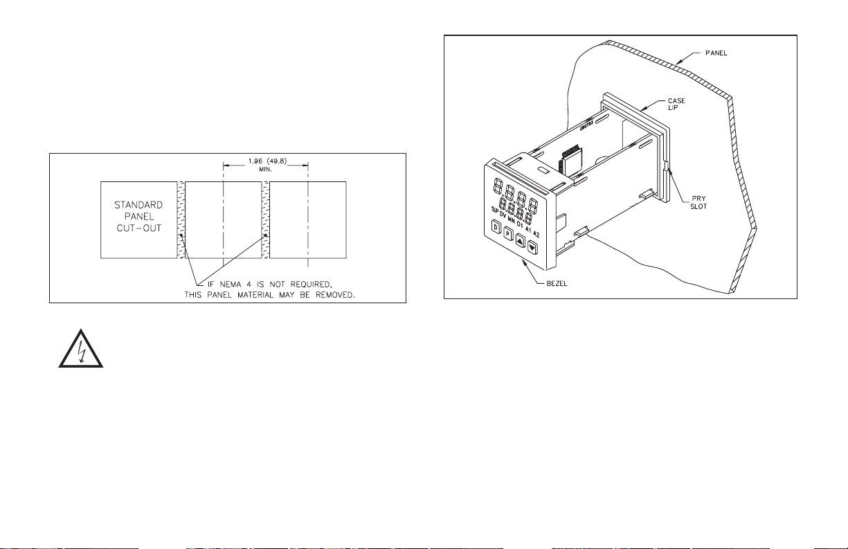
MULTIPLE UNIT STACKING
The controller is designed for close spacing of multiple units. Units can be
stacked either horizontally or vertically. For vertical stacking, install the
panel latch with the screws to the sides of the unit. For horizontal stacking, the
panel latch screws should be at the top and bottom of the unit. The minimum
spacing from center line to center line of units is 1.96" (49.8 mm). This
spacing is the same for vertical or horizontal stacking.
Note: When stackingunits, provide adequate panel ventilation to ensure that
the maximum operating temperature range is not exceeded.
Figure 2, Multiple Unit Stacking Horizontal Arrangement
Caution: Disconnect power to the unit and to the output
control circuits to eliminate the potential shock hazard
when removing the bezel assembly.
UNIT REMOVAL PROCEDURE
To remove a unit from the panel, first loosen the p anel latch screws. Insert
flat blade screwdrivers between the latch and the case on either side of the
unit, so that the latches disengage from the grooves in the case. Push the unit
through the panel from the rear.
REMOVING BEZEL ASSEMBLY
The bezel assembly, shown in Figure 3, must be removed from the case to
replace the output board. To remove the bezel assembly, insert a flat blade
screwdriver into the pry slot on either side of the unit. Twist the screwdriver
handle until the unit is ejected enough to allow removal.
Figure 3, Bezel Assembly
Caution: The bezel assembly contains electronic circuits that can be damaged by
static electricity. Before removing the assembly, discharge static charge on
your body by touching an earth ground point. It is also important that the bezel
assembly be handled only by the bezel itself. Additionally, if it is necessary to
handle a circuitboard,becertain that hands are freefromdirt,oil, etc., to avoid
circuit contamination that may lead to malfunction. If it becomes necessary to
ship the unit for repairs, place the unit in its case before shipping.
INSTALLING BEZEL ASSEMBLY
To install the bezel assembly, insert the assembly into the case until the
bezel is fully seated against the lip of the case. Properly installing the bezel
assembly is necessary for watertight sealing.
-3-

CONNECTION DESCRIPTION
EMC INSTALLATION GUIDELINES
Although this unit is designed with a high degree of immunity to Electro
Magnetic Interference (EMI), proper installation and wiring methods must be
followed to ensure compatibility in each application. The type of the
electrical noise, source or coupling method into the unit may be different for
various installations. Listed below are some EMC guidelines for successful
installation in an industrial environment.
1. The unit should be mounted in a metal enclosure, which is properly
connected to protective earth.
2. Use shielded (screened) cables for all Signal and Control inputs. The shield
(screen) pigtail connection should be made as short as possible. The
connection point for the shield depends somewhat upon the application.
Listed below are the recommended methods of connecting the shield, in
order of their effectiveness.
a. Connect the shield only at the panel where the unit is mounted to earth
ground (protective earth).
b. Connect the shield to earth ground at both ends of the cable, usually
when the noise source frequency is above 1 MHz.
c. Connect the shield to common of the unit and leave the other end of the
shield unconnected and insulated from earth ground.
3. Never run Signal or Control cables in the same conduit or raceway with AC
power lines, conductors feeding motors, solenoids, SCR controls, and
heaters, etc. The cables should be run in metal conduit that is properly
grounded. This is especially useful in applications where cable runs are
long and portable two-way radios are used in close proximity or if the
installation is near a commercial radio transmitter.
4. Signal or Control cables within an enclosure should be routed as far away
as possible from contactors, control relays, transformers, and other noisy
components.
5. In very electrically noisy environments, the use of external EMI
suppression devices, such as ferrite suppression cores, is effective. Install
them on Signal and Control cables as close to the unit as possible. Loop the
cable through the core several times or use multiple cores on each cable for
additional protection. Install line filters on the power input cable to the unit
to suppress power line interference. Install them near the power entry point
of the enclosure.
The following EMI suppression devices (or equivalent) are recommended:
Ferrite Suppression Cores for signal and control cables:
Fair-Rite # 0443167251
TDK # ZCAT3035-1330A
Steward #28B2029-0A0
Line Filters for input power cables:
Schaffner # FN610-1/07
Schaffner # FN670-1.8/07
Corcom #1VR3
Note: Reference manufacturer’s instru ctions when installing a line filter.
6. Long cable runs are more susceptible to EMI pickup than short cable runs.
Therefore, keep cable runs as short as possible.
7. Switching of inductive loads produces high EMI. Use of snubbers across
inductive loads suppresses EMI.
-4-
WIRING CONNECTIONS
After the unit has been mechanically mounted, it is ready to be wired. All
wiring connections are made to the rear screw terminals. When wiring the
unit, use the numbers on the label and those embossed on the back of the case,
to identify the position number with the proper function.
All conductors should meet voltage and current ratings for each terminal.
Also cabling should conform to appropriate standards of good installation,
local codes and regulations. It is recommended that power supplied to the unit
(AC or DC) be protected by a fuse or circuit breaker. Strip the wire, leaving
approximately 1/4" (6 mm) bare wire exposed (stranded wires should be
tinned with solder). Insert the wire under the clamping washer and tighten the
screw until the wire is clamped tightly.
Caution: Unused terminals are NOT to be used as tie points. Damage to the
controller may result if these terminals are used.
SIGNAL WIRING
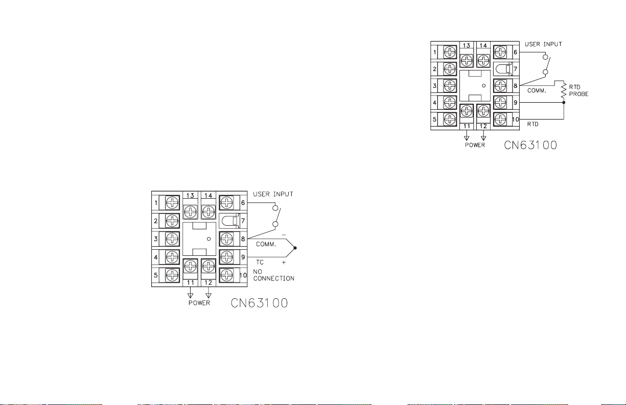
Thermocouple (CN63100)
When connecting the
thermocouple, be certain that
the connections are clean and
tight, refer to Figure 4 for
terminal connections. If the
thermocouple probe cannot
be connected directly to the
controller, thermocouple wire
or thermocouple
extension-grade wire must be
used to extend the connection
points (copper wire does not
work). Always refer to the
thermocouple manufacturer’s
recommendations for
mounting, temperature range,
shielding, etc. For multi-probe temperature averaging applications, two or
more thermocouple probes may be connected to the controller (always use the
same type). Paralleling a single thermocouple to more than one controller is
not recommended. Generally, the red wire from the thermocouple is negative
and connected to the controller’s common.
Figure 4, Thermocouple Connection
RTD (CN63100)
When connecting the
RTD, be certain that the
connections are clean and
tight, refer to Figure 5 for
terminal connections. RTD
sensors have a higher
degree of accuracy and
stability than thermocouple
sensors. Most RTD sensors
available are the three wire
type. The third wire is a
sense lead f or canceling the
effects of lead resistance of
the probe. Four wire RTD
elements may be used by
leaving one of the sense
leads disconnected. Two wire RTD sensors may be used in either of two ways:
A) Attach the RTD to terminals #8 and #10. Install a copper sense wire of the
same wire gage as the RTD leads. Attach one end of the wire at the probe
and the other end to terminal #9. Complete lead wire compensation is
obtained. This is the preferred method.
B) Attach the RTD to terminals #8 and #10. Install a shorting wire between
terminals #9 and #10, as shown in Figure 5, RTD Connection. A
temperature offset error of 2.5°C/ohm of lead resistance exists. The error
may be compensated by programming a temperature offset.
Note: With extended cable runs, be sure the lead resistance is less than 15
ohms/lead. For thermocouple or RTD runs longer than 100 feet, convert the
signal to acurrent near the temperature probe. Currentor 20 mA loop signals
are less susceptible to noise and signal loss than long thermocouple or RTD
runs. By converting thetemperature signal, the CN63300 can beused in place
of a CN63100.
-5-
Figure 5, RTD Connection
Signal (CN63300)
When connecting signal
leads, be certain that the
connections are clean and
tight. For voltage signals, use
terminal #8 for common and
terminal #9 for signal. For
current signals, use terminal
#8 for common and terminal
#10 for signal. These
connections are shown in
Figure 6. Multicontroller
applications using the same
signal source are possible, by
connecting current signals in
series, and voltage signals in
parallel.
Figure 6, CN63300 Signal Connection
CONTROL AND ALARM OUTPUTS
For CN63100 heating, cooling, and alarms, there are up to two types of
ON/OFF outputs. These outputs can be relay, or logic for control or alarm
purposes. Relay outputs can switch user applied AC or DC voltages.
Logic/SSR drive outputs supply power to external SSR power units. One
Logic/SSR Drive output can control up to four SSR power units at one time.
The CN63300 is only available with relay outputs. Terminal numbers for the
outputs and output types vary from model to model. Refer to the Rear
Terminal Assignment Tables or the label on the controller for the terminal
numbers corresponding to the model being wired.
Relay Connections
To prolong contact life and suppress electrical noise interference due to the
switching of inductive loads, it is good installation practice to install a snubber
across the contactor. Follow the manufacturer’s instructions for installation.
Note: Snubber leakage current can cause some electromechanical devices to be
held ON.
POWER WIRING
AC Power
Primary AC power is connected to terminals #11 and #12, labeled AC. To
reduce the chance of noise spikes entering the AC line and affecting the
controller, an AC feed separate from that of the load should be used to power
the controller. Be certain that the AC power to the controller is relatively
“clean” and within the variation limit. Connecting power from heavily loaded
circuits or circuits that also power loads that cycle on and off, (contacts,
relays, motors, etc.) should be avoided.
DC Power
DC power (18 to 36 VDC) is connected to terminals #11 and #12 labeled
DC+ and DC- respectively.
CAUTION: Observe proper polarity when connecting DC voltages.
Damage to the unit may occur if polarity is reversed.
Relay Outputs:
Type: Form-A
Rating: 3 Amps @ 250 VAC or 30 VDC (resistive load), 1/10 HP @ 120
VAC (inductive load).
Life Expectancy: 100,000 cycles at maximum load rating. (Decreasing
load and/or increasing cycle time, increases life expectancy).
Figure 7, Relay Output
-6-
Logic/SSR Connections (CN63100 only)
Logic/SSR Drive Output:
Rating: 45 mA @ 4 V min., 7 V nominal (current limited)
Figure 8, Logic/SSR Output
REMOTE SETPOINT WIRING
Models with the Remote Setpoint option have two input terminals to
receive a 0 to 20 mA signal. Connect the Remote Setpoint signal to terminals
labeled #13 (+) and #14 (-), “2nd Input Option”. The common of this input is
isolated from input common, but is not isolated from the Linear DC output
commons. For proper operation, keep this common isolated from all other
controller commons.
MAIN LINEAR DC OUTPUT WIRING
Models with the Linear DC output option provide either a linear 10 V or a
linear 20 mA signal. The output range is selected by jumpers on the output
board. (See Linear DC Analog Output Jumper Selection, page 11). The
terminals are #1 (-) and #2 (+). The common of this output is isolated from
input common, but is not isolated from other commons. For proper operation,
keep this common isolated from all other controller commons.
SECOND LINEAR DC OUTPUT WIRING
Models with the Second Linear DC output option provide a conditioned
and scaled retransmitted signal output. The terminals are #13 (+) and #14 (-).
The common of this output is isolated from the input common, but not from
the other commons. For proper operation, keep this common isolated from all
other controller commons.
USER INPUT WIRING
The use of shielded cable is recommended. Follow the EMC installation
guidelines for shield connection.
Terminal #6 is the User Input, which is programmable for a variety of
functions. Any form of mechanical switch may be connected to terminal #6
(USER INPUT) and terminal #8 (COMM.). Sinking open collector logic with
less than 0.7 V saturation and off-state leakage current of less than 1 μAmay
also be used.
-7-
REAR TERMINAL ASSIGNMENTS
CN63100 Models Without RS-485 and Analog Output
TC RTD AC/DC Power A2 or 02
(+) (-) Short (C) AC/(+) AC/(-) (C) (C) (C) (C) (+) (-)
989108 11 12 4 5 6 8 -R1 -R1-LV
9 8 9 10 8 11 12 1 2 3 2 4 5 6 8 -R1-R2-AL -R1-R2-AL-LV
9 8 9 10 8 11 12 1 2 3 2 4 5 6 8 13 14 -R1-R2-AL-RSP -R1-R2-AL-RSP-LV
9 8 9 10 8 11 12 4 5 6 8 -DC1 -DC1-LV
9 8 9 10 8 11 12 1 2 3 2 4 5 6 8 -DC1-R2-AL -DC1-R2-AL-LV
(C) is the Common Terminal
Terminals 9 & 10 need to be shorted together.
* Remote Setpoint
DedicatedA1Dedicated
O1
User Input
2nd Input
Option *
AC Model # DC Model #
CN63100 Models With RS-485 or Linear DC Analog Output
TC RTD
(+) (-) Short (C) AC/(+) AC/(-) (+) (-) (C) (C) (C) (C) (C) A(+) B(-) (+) (-) (+) (-)
9 8 9 10 8 11 12 2 1 3 4 5 4 6 8 13 14 -R1-R2-F3 -R1-R2-F3-LV
9 8 9 10 8 11 12 2 1 3 4 5 4 6 8 13 14 -R1-R2-F3-RSP -R1-R2-F3-RSP-LV
9 8 9 10 8 11 12 2 1 3 4 5 4 6 8 13 14 -R1-R2-F3-C4 -R1-R2-F3-C4-LV
9 8 9 10 8 11 12 1 2 3 2 4 5 6 8 13 14 -R1-R2-AL-C4 -R1-R2-AL-C4-LV
9 8 9 10 8 11 12 1 2 3 2 4 5 6 8 13 14 -DC1-R2-AL-C4 -DC1-R2-AL-C4-LV
(C) is the Common Terminal
Terminals 9 & 10 need to be shorted together.
* Remote Setpoint
AC/DC
Power
Analog
Main Out
A2 or O2
Dedicated
A1
O1 or A1
DedicatedO1User
Input
RS485
Output
2nd Input
Option *
Analog
2nd Out
AC Model # DC Model #
-8-
REAR TERMINAL ASSIGNMENTS
ALL CN63300 Models
0 - 10V
0-20mA
Input
(+) (-) (+) (-) AC/(+) AC/(-) (+) (-) (C) (C) (C) (C) (C) A(+) B(-) (+) (-)
9 8 10 8 11 12 4 5 6 8 -R1 -R1-LV
9 8 10 8 11 12 2 1 3 4 5 4 6 8 -R1-R2-F3 -R1-R2-F3-LV
9 8 10 8 11 12 2 1 3 4 5 4 6 8 13 14 -R1-R2-F3-RSP -R1-R2-F3-RSP-LV
9 8 10 8 11 12 2 1 3 4 5 4 6 8 13 14 -R1-R2-F3-C4 -R1-R2-F3-C4-LV
9 8 10 8 11 12 1 2 3 2 4 5 6 8 -R1-R2-AL -R1-R2-AL-LV
9 8 10 8 11 12 1 2 3 2 4 5 6 8 13 14 -R1-R2-AL-C4 -R1-R2-AL-C4-LV
(C) is the Common Terminal.
* Remote Setpoint Input.
Input
AC/DC
Power
Analog
Main Out
A2 or O2
Dedicated
A1
O1 or A1
DedicatedO1User
Input
RS485
Output
2nd Input
Option *
AC Model # DC Model #
-9-
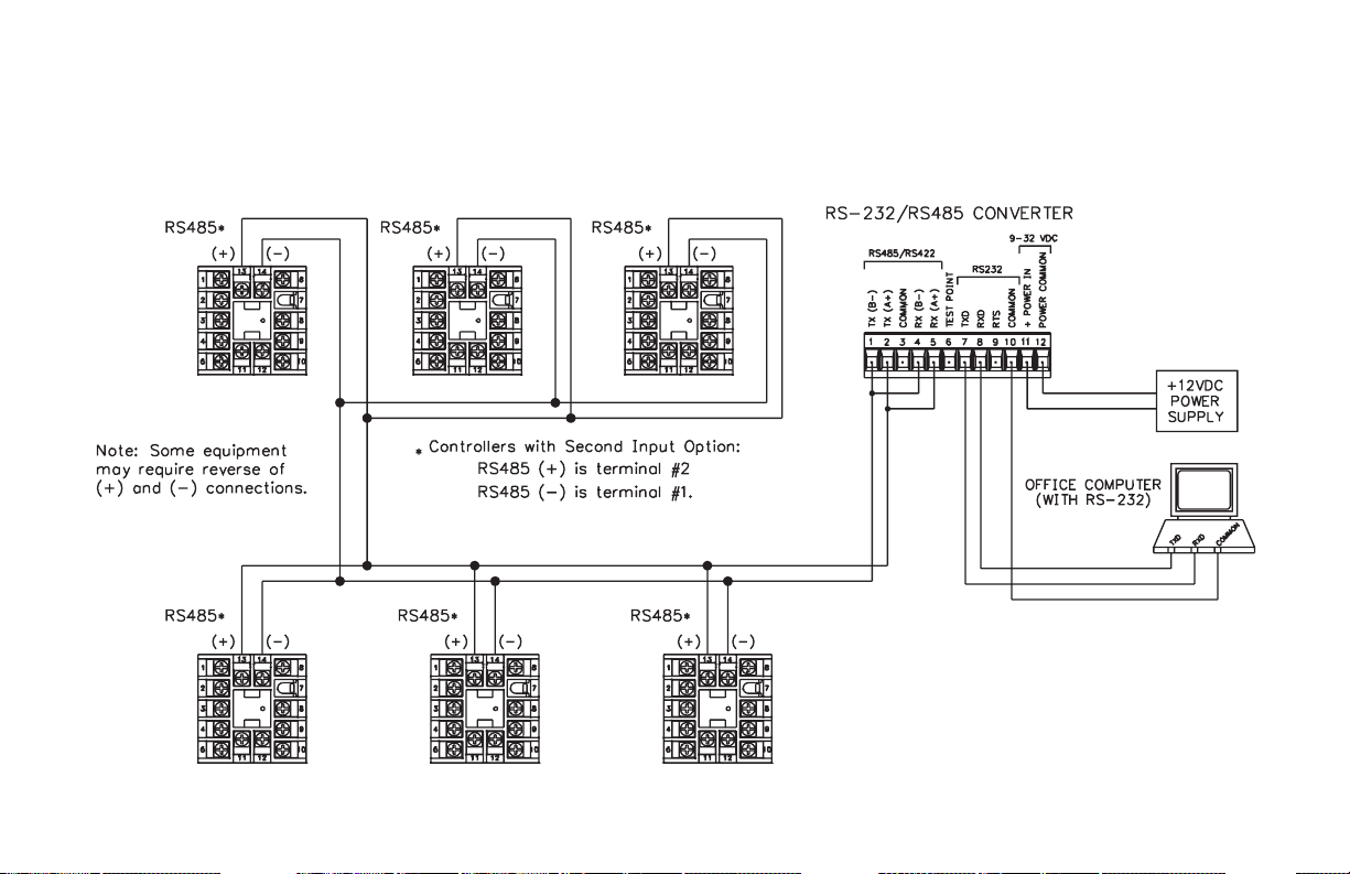
SERIAL CONNECTIONS TO A HOST TERMINAL
Six controllers are used to monitor and control parts packaging machines
in a plant. The controllers are located at each machine in the production area
of the building. A communication line is run to an industrial computer located
in the production office.
Each controller is programmed for a different address and all are
programmed for the same baud rate and parity as the computer (ex. 9600
baud, parity even). An application program is written by the user to send and
receive data from the units using the proper commands.
Figure 9, Connecting to a Host Terminal
-10-
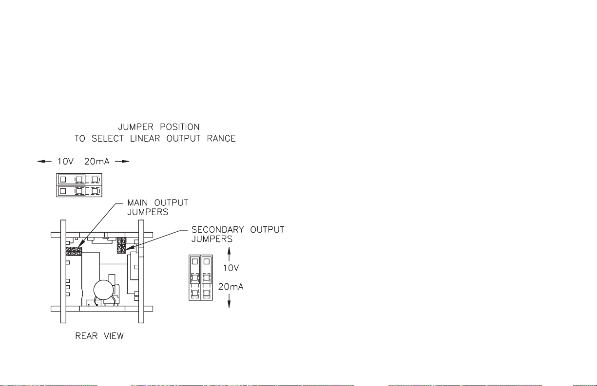
LINEAR DC ANALOG OUTPUT JUMPER SELECTION
(Main & Second)
The Linear Analog DC Output ranges are selectable for either voltage
(0-10 V) or current (0/4-20 mA). The main set of jumpers must correspond
with the configuration in Linear Output Range (ANAS) in the Output
Parameter Module (2-OP). The optional secondary set of jumpers must
correspond with the configuration in Second Linear DC Output Range (A2tP)
in the Second Linear DC Analog Output Module (8-A2). The jumpers are
accessible f rom the rear after removing the controller from the case. Dashed
lines show factory s etting of 20 mA.
Figure 10, Linear Output Range Jumpers
-11-
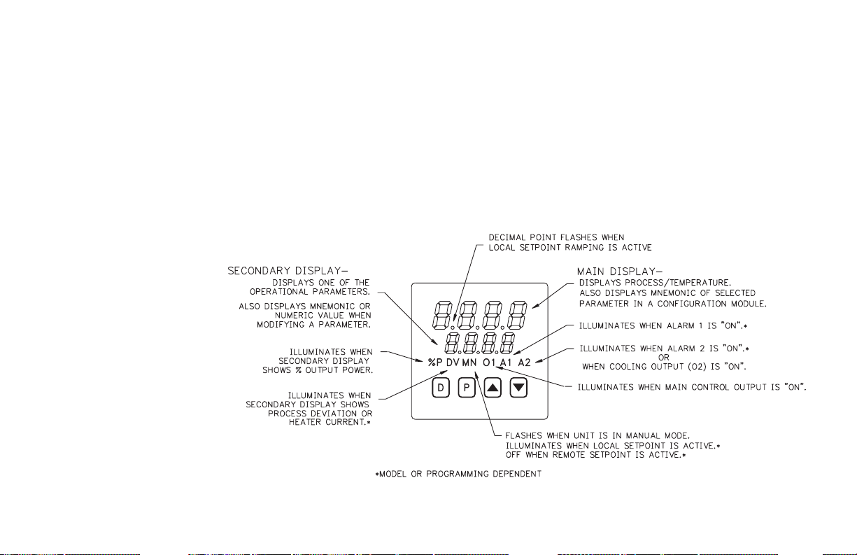
FRONT PANEL DESCRIPTION
The front panel bezel material is flame and scratch resistant, tinted plastic
that meets NEMA 4X/IP65 requirements, when properly installed.
Continuous exposure to direct sunlight may accelerate the aging process of
the bezel. The bezel should be cleaned only with a soft cloth and neutral soap
product. Do NOT use solvents. There are two 4-digit LED displays, a red
upper Main Display and a lower green Secondary Display.
There are up to six annunciators, with red backlighting, that illuminate to
inform the operator of the controller and output status. See Figure 11, Front
Panel, for a description of the annunciators.
Four front panel buttons are used to access different modes and
parameters. The following is a description of each button.
Do NOT use tools of any kind (screwdrivers, pens, pencils, etc.) to operate the
keypad of this unit.
BUTTON FUNCTIONS
D - In the Normal Display Mode, the
Display (D) button is used to
select one of the operational
parameters in the secondary
display. In other modes, pressing
the D button causes the controller
to exit (escape) directly to the
Normal Display Mode.
P - The Parameter (P) button is used
to access programming, enter the
change, and scroll through the
available parameters in any mode.
UP, DN - In the Normal Display
Mode, the Up/Down (L /M)
buttons can be used to directly
modify the setpoint value or
% output power (manual control
only), when viewed in the
secondary display.
Figure 11, Front Panel
-12-

INITIAL CONFIGURATION START-UP
CONTROLLER POWER-UP
Upon applying power, the controller delays input indication and control
action for five seconds to perform several self-diagnostic tests and to display
basic controller information. Initially, the controller illuminates both
displays and all annunciators to verify that all display elements are
functioning. The controller then displays the programmed input sensor type
in the main (top) display and the revision number of the controller’s operating
system software in the secondary (bottom) display. The controller checks for
correct internal operation and displays an error message (E-xx) if an internal
fault is detected. (See Troubleshooting, page 71, for further information).
Upon completion of this sequence, the controller begins displaying the
input value and updating the outputs based upon the control calculation.
PARAMETER CONFIGURATION OVERVIEW
The controller is programmed with certain parameter settings from the
factory. Factory settings are listed in parentheses in the various Configuration
of Parameters tables. In many cases, these settings must be changed to the
particulars of the application before proper operation can be started.
The controller is typically in the Normal Display Mode. When changes to
parameter configurations are needed, the P button is pressed. From the factory,
the controller will enter directly into the Unprotected Parameter Mode.
Continue to press the P button until CnFP appears in the bottom display. At this
time, press the Up arrow button and 1-In will appear in the bottom display. This
will be the Configuration Parameter Mode. This programming flow is shown in
the Front Panel Programming Chart. (If at any time during front panel
programming the D button is pressed, the controller will return to the Normal
Display Mode and the programming can be started over.)
In the Configuration Parameter Mode, the Up or Down arrow buttons can
be pressed to move to the desired Parameter Module. The P button is then
pressed to enter into that module. The main (top) display will be the parameter
and the secondary (bottom) display will be the parameter value. The Up or
Down arrow buttons are used to change the desired parameter value and the P
button enters the new value and moves to the next parameter.
The Setpoint value (lower display) is changed with the Up or Down arrow
buttons when it is selected in the Normal Display Mode.
PARAMETER CONFIGURATION BASIC START-UP
For basic start-up, it is important to verify or change Input Parameter
Module (1-IN) parameters tYPE and SCAL, and Output Parameter Module
(2-OP) parameter OPAC. For alarm and heat/cool set-up, it is important to
verify or change Alarms Parameter Module (4-AL) parameters ACt1, AL-1,
ACt2 and AL-2.
If the above Input Parameters or the input wiring connections are not
correct, then the main (top) display may display an error message or incorrect
value. Verify the input programming and wiring. (If incorrect display
continues refer to Troubleshooting, page 71.) All other parameter
configurations are important but will not prevent the controller from showing
a correct display.
PARAMETER CONFIGURATION FOR SERIAL START-UP
The parameter settings can be changed by the front panel button. For serial
communications set-up, it is important to check serial wiring and verify or
change Serial Parameter Module (6-SC) parameters bAUd, ConF,s and Addr.
(See Serial Communications Interface, page 57, for more details.)
CONTROL START-UP
After verifying proper programming and system start-up, a controlling
method needs to be configured. For Manual Control or open loop, where the
control does not work from the setpoint or process feedback, see Manual
Control, page 46. For On / Off Control, set Proportional Band Prop to 0.0%
and see On / Of f Control, page 47. The controller comes with factory setting
for PID Control. However, for optimum PID Control, several options exist
for configuring Proportional Band, Integral Time, and Derivative Time
parameters for specific applications.
a. Use controller’s built-in Auto-Tune feature (See Auto-Tune For PID
Control, page 50).
b. Use a manual tuning technique (See Manual Tuning For PID Control,
page 55).
c. Use a third party tuning software package.
d. Use values based on control loop experience, calculated values or values
from a similar process or previous controller.
-13-
VALID CONTROL MODE COMBINATIONS
ON/OFF, PID, and Manual Control can be used for O1 (heat) and O2 (cool)
outputs according to the combinations below.
O1 & O2 VALID CONTROL MODES
O1 MODE O2 MODE
PID — 0% to +100% O1-TP —
ON/OFF
(ProP = 0.0)
PID PID -100% to +100% O1-TP O2-TP
PID ON/OFF
ON/OFF
(ProP=0.0)
TP - Time Proportioning
— 100% O1-ON —
(GAN2=0.0)
ON/OFF
(GAN2=0.0)
MANUAL CONTROL
OUTPUT POWER
RANGE
Any other setting O1-OFF —
0% to +100% O1-TP O2-OFF
-100% to 0% O1-TP O2-ON
+100% O1-ON O2-OFF
-100% O1-OFF O2-ON
Any other setting O1-OFF O2-OFF
O1 STATE O2 STATE
-14-
FRONT PANEL PROGRAMMING CHART FOR CN63100 & CN63300 CONTROLLERS
-15-
NORMAL DISPLAY MODE
In the Normal Display Mode, the temperature or scaled process value is
displayed in the main (top) display. By successively pressing the D button,
the parameters listed below can be viewed in the secondary (bottom) display.
Each of these parameters can be independently locked out from appearing or
from being modified through the Lockout Parameter 3-LC. If all four displays
are locked out, the display blanks after pressing the D button. To gain access
to the next modes, press the P button from any parameter.
To modify values in % Output Power (for Manual Control) or Setpoint, use
the Up or Down arrows while the parameter is displayed and not locked. If
locked, these parameters can be changed in the Protected Parameter Mode. The
controller responds to the new values immediately, however, the change is not
committed to permanent memory until 10 seconds after the last key press.
Normal Display Mode Reference Table
Illuminates Parameter
—- Local Setpoint
SP1 or SP2
%P % Output
Power
DV Setpoint
Deviation
—- Units Symbol °For° C
—- Blank Blank display
Range and Units
(Factory Setting)
-999 to 9999
(0) for CN63100
(0.0) for CN63300
-99.9% to 100.0%
Read only Unless in
Manual Control
-999 to 9999
Read only
Read only
Description/Comments
Range limited by
SPLO & SPHI in 1-In.
Not limited by
OPLO & OPHI in 2-OP.
Shows difference
between Temp/Process
(top display) and
Setpoint.
CN63100 models only
CN63300 models only
FRONT PANEL PROGRAM DISABLE
There are several ways to limit the programming of parameters from the
front panel buttons. The settings of the parameters in the Lockout Module
3-LC, the code number entered, and the state and/or function programmed for
the User Input (Terminal #6) will all affect front panel access.
The following chart describes the possible program disable settings.
User Input State Code Number Description
Inactive or User
Input not
programmed for
PLOC
Active with User
Input programmed
for PLOC
Active with User
Input programmed
for PLOC
OR
User Input not
programmed for
PLOC
Note: A universal code number 222 can be entered to gain access to the
unprotected mode and configuration modules, independent of the
programmed code number.
0 Full access to all modes and
0 Access to protected parameter
Any # between
1 & 250
parameter modules.
mode only. Code number does not
appear.
Access to protected parameter
mode. Correct programmed code
number allows access to
unprotected parameter mode and
configuration modules.
-16-

UNPROTECTED PARAMETER MODE
The Unprotected Parameter Mode is accessed by pressing the P button
from the Normal Display Mode with Program Disable inactive. While in this
mode, the operator has access to the most commonly modified controller
parameters by pressing the P button. The temperature or scaled process value
is displayed in the main (top) display. The parameter display will appear with
the corresponding range and units in the secondary (bottom) display.
To modify values, use the Up or Down arrows while the parameter is
displayed. The controller responds to the new values immediately, however,
the change is not committed to non-volatile memory until the controller is
returned to the Normal Display Mode. If power loss occurred before
returning to the Normal Display Mode, the new values must be entered again.
To gain access to the Configuration Parameter Modules, continue to CnFP
and press the Up arrow. These modules allow access to the fundamental
set-up parameters of the controller. When the program list has been scrolled
through, or the D button is pressed, the controller displays “End” and returns
to the normal display mode. The unit automatically returns to the Normal
Display Mode if no action is taken.
Unprotected Parameter Mode Reference Table
Display Parameter
SP Local **
Setpoint
SP1 or SP2 *
OPOF %Output **
Power Offset
OP % Output **
Power
ProP Proportional
Band
Intt Integral
Time
dErt Derivative
Time
AL-1 Alarm 1
Value *
AL-2 Alarm 2
Value *
CNFP Configuration
Access Point
End Returns to
Normal
Display Mode
* Model Number Dependent.
** Only appears if locked out from Normal Display Mode.
Range and Units
(Factory Setting)
-999 to 9999
(0) CN63100
(0.0) CN63300
-99.9% to 100.0%
(0.0)
-99.9% to 100.0%
(0.0)
0.0 to 999.9% of
selected input
range
(4.0) CN63100
(100.0) CN63300
0 to 9999 sec.
(120) CN63100
(40) CN63300
0 to 9999 sec.
(30) CN63100
(4) CN63300
-999 to 9999,
(0) CN63100
(0.0) CN63300
-999 to 9999,
(0) CN63100
(0.0) CN63300
Up Arrow
____ Brief display message while the
Description/ Comments
Range limited by SPLO & SPHI.
User Input or Hidden Function
Mode selects SP1 or SP2
Appears only if Intt = 0 and unit
is in Automatic Control.
Appears only if unit is in
Manual Control. This parameter
is not limited to output power
limits (OPLO & OPHI).
0.0% is ON/OFF control. If
using ON/OFF, set control
hysteresis appropriately.
0 is off. This parameter does
not appear if ProP = 0.0%.
0 is off. This parameter does
not appear if ProP = 0.0%.
This parameter does not appear
if configured for “heat”.
This parameter does not appear
if configured for “cool”.
NO
Return to Normal Display Mode.
Enter Configuration modules.
unit returns to Normal Display
Mode.
-17-

PROTECTED PARAMETER MODE
The Protected Parameter Mode is accessed by pressing the P button from
the Normal Display Mode with Program Disable active. While in this mode,
the p arameters can be accessed by pressing the P button. The temperature or
scaled process value (after initial setup) will be displayed in the main (top)
display. The parameter display will appear with the corresponding range and
units in the secondary (bottom) display. Each of these parameters can be
independently locked out from appearing or from being modified through the
Lockout Parameter 3-LC.
To modify values, use the Up or Down arrows while the parameter is
displayed. If locked, the parameter will not show in the Normal Display
Mode, but can be changed in the Protected Parameter Mode. The controller
responds to the new values immediately, however, the change is not
committed to non-volatile memory until the controller is returned to the
Normal Display Mode. If power loss occurred before returning to the Normal
Display Mode, the new values must be entered again.
To gain access to the Unprotected Parameter Mode (with User Input
inactive or not programmed for PLOC), continue to CodE and press the arrow
buttons until the value equals the Code as entered in parameter lockouts.
When an incorrect code value is entered, or when the D button is pressed,
“End” will momentarily appear and the controller will return to the Normal
Display Mode.
Protected Parameter Mode Reference Table
Display Parameter
ProP Proportional
Band
Intt Integral
Time
dErt Derivative
Time
AL-1 Alarm 1
value *
AL-2 Alarm 2
value *
CodE Access
code to
Unprotected
Parameter
Mode
End Returns to
Normal
Display
Mode.
* Model Number Dependent.
Range and Units
(Factory Setting)
0.0 to 999.9% of
selected input
range
(4.0) CN63100
(100.0) CN63300
0 to 9999 sec.
(120) CN63100
(40) CN63300
0 to 9999 sec.
(30) CN63100
(4) CN63300
-999 to 9999
(0) CN63100
(0.0) CN63300
-999 to 9999
(0) CN63100
(0.0) CN63300
0to250
(0)
—-
Description/Comments
0.0% is ON/OFF Control.
Adjusted by Auto-Tune.
0 is off. This parameter does not
appear if ProP = 0.0%. Adjusted
by Auto-Tune.
0 is off. This parameter does not
appear if ProP = 0.0%. Adjusted
by Auto-Tune.
This parameter does not appear
if configured for “heat”.
This parameter does not appear
if configured for “cool”.
To gain access to Unprotected
Parameter Mode, enter the same
value for Code as used in
parameter lockouts. Does not
appear if zero is entered in code
parameter lockout.
Brief display message while the
unit returns to Normal Display
Mode.
-18-

HIDDEN FUNCTION MODE
The Hidden Function Mode is only accessible from the Normal Display
Mode by pressing and holding the P button for three seconds. These
functions must first be unlocked in Configuration Module 3 -LC. Factory
settings for these parameters is lock. In this mode, these controller functions
can be performed.
buttons are used to select the operation. Pressing the P button while the
function is displayed executes the function, and returns the unit to the Normal
Display Mode. Pressing the D button exits this mode with no action taken.
The unit automatically returns to the Normal Display Mode if no action is
taken within a few seconds.
Hidden Function Mode Reference Table
Display Parameter
SPSL Setpoint
trnF Transfer
tUNE Auto-tune
ALrS Alarm
* Model Number Dependent
Remote/SP1/SP2 Setpoint Selection
Automatic/Manual Transfer
Initiate/Cancel Auto-tune
Reset Alarm Outputs
The P button is used to scroll to the desired function and the Up and Down
Select
mode of
operation
Invocation
Reset *
Range and Units
(Factory Setting Value)
SP1 - Setpoint 1
SP2 - Setpoint 2
rSP - Remote Setpoint
Auto - Automatic control
User - Manual control
(Auto)
Yes: starts the
auto-tune sequence.
No: terminates the
auto-tune sequence.
(NO)
UP button resets Alarm 1
DOWN button resets
Alarm 2
Description/ Comments
Exits to Normal Display
Mode after being executed.
Exits to Normal Display
Mode after being executed.
Exits to Normal Display
Mode after being executed.
Does not exit to Normal
Display Mode after being
executed.
CONFIGURATION PARAMETER MODE
The Configuration Parameter Mode is accessed by pressing the Up button
from CnFP in the Unprotected Parameter Mode. While in this mode, the
various Configuration Modules can be displayed by pressing the Up or Down
buttons. The process value (after initial setup) will be displayed in the main
(top) display. The Configuration Module will appear alternating with CnFP
in the secondary (bottom) display.
To access a Configuration Module, press the P button when the desired
Configuration Module is displayed. The parameters of that Configuration
Module can be accessed by pressing the P button. (The module’s parameters
are listed in the appropriate Configuration Module table in this section with
configuration parameter explanations beginning on page 30.) To modify
ranges and units, use the Up or Down arrows while the parameter is displayed.
The controller responds to the new values after the P button is pressed,
however, the change is not committed to permanent memory until the
controller is returned to the Normal Display Mode. If power loss occurred
before returning to the Normal Display Mode, the new values must be entered
again. Whenever the D button is pressed, End will momentarily appear and
the controller will return to the Normal Display Mode. At the end of each
module, the controller will go to CnFP no. Pressing the Up or Down arrows
will continue in Configuration Parameter Mode and pressing the P will return
to the Normal Display Mode.
Unless specified, the parameters, ranges, units and factory settings are the
same for CN63100 and CN63300 controllers. Parameters that are model
number or program dependent will only be displayed when the appropriate
options are installed or programmed. Some parameters are accessible but may
not be applicable for the chosen output control mode type.
-19-
REFERENCE TABLES: CONFIGURATION PARAMETER MODULES
Configure Module 1 - Input Parameters (1-IN) CN63100
These tables are only used for programming the CN63100 models.
Use the tables on page 21 if you are programming a CN63300.
Display Parameter
tYPE Input Type tc-t - Type T TC
SCAL Temperature
Scale
dCPt Temperature
Resolution
FLtr Digital Input
Filtering And
Display
Update
Range and Units
(Factory Setting)
tc-E - Type E TC
tc-J - Type J TC
tc-k - Type K TC
tc-r-TypeRTC
tc-S - Type S TC
tc-b - Type B TC
tc-N - Type N TC
LIN - Linear mV display
r385 - 385 curve RTD
r392 - 392 curve RTD
rLIN - Linear ohms display
(tc-J)
°F/°C
(°F)
0or0.0
(0)
0to4
(1)
Description/
Comments
Thermocouple select
RTD select
If scale is changed,
be sure to check all
parameters.
If resolution changed,
be sure to check all
parameters.
Increase number for
more filtering effect.
4 = 500 msec display
update rate. Adjusted
by Auto-Tune.
Display Parameter
SHFt Input Signal
Shift (correction
offset)
SPLO Setpoint Lower
Limit
SPHI Setpoint Upper
Limit
SPrP Setpoint Ramp
Rate
InPt User Input * PLOC - Program disable
Range and Units
(Factory Setting)
-999 to 9999
1 or 0.1 degree
(0)
-999 to 9999
0 or 0.1 degree
(0)
-999 to 9999
1 or 0.1 degree
(9999)
0.0 to 999.9 degrees/minute
(0.0)
ILOC - Integral action on/off
trnF - Auto/manual select
SPrP - Setpoint ramp on/off
ALrS - Reset alarm output(s)
SP2 - Select SP1/SP2
rSP - Select
Local/Remote
PrNt - Serial block print
(PLOC)
* Model Number Dependent
-20-
Description/
Comments
Normally set to 0.
Set low limit
below high limit.
Set high limit
above low limit.
0.0 is off (no
ramping)
Low = lock
Low = off
Low = manual
Low = end ramp
Low = reset
Low = SP2
Low =remote
Low =block print
 Loading...