

Page 1

Products manufactured and sold by OMEGA RESEARCH & DEVELOPMENT, INC. (the Company),
LIMITED LIFETIME WARRANTY
are warranted to be free from defects in materials and workmanship under normal use. If a
product sold by the Company proves to be defective, the Company will repair or replace it free
of charge within the first year and thereafter all parts to be repaired will be free with only a
nominal charge for Omega Research and Development, Inc.'s labor and return shipping, to the
original owner during the lifetime of the car in which it was originally installed.
All products for warranty repair must be sent postage prepaid to Omega Research &
Development, Inc., P.O. Box 508, Douglasville, Georgia 30133, with bill of sale or other dated proof
of purchase. This warranty is nontransferable and does not apply to any product damaged by
accident, physical or electrical misuse or abuse, improper installation, alteration, any use contrary
to its intended function, unauthorized service, fire, flood, lightning, or other acts of God.
This warranty limits the Company's liability to the repair or replacement of the product. The
Company shall not be responsible for removal and/or reinstallation charges, damage to or theft of the
vehicle or its contents, or any incidental or consequential damages caused by any failure or alleged
failure of the product to function properly. Under No Circumstances Should This Warranty, Or The
Product Covered By It, Be Construed As A Guarantee Or Insurance Policy Against Loss. The
Company neither assumes nor authorizes any person or organization to make any Warranties or
assume any liability in connection with the sale, installation, or use of this product.
This device complies with part 15 of the FCC Rules. Operation is subject to the following two conditions: (1) This device may not cause harmful
interference and, (2) This device must accept any interference received, including interference that may cause undesired operation.
The manufacturer is not responsible for any radio TV interference caused by unauthorized modifications to this equipment. Such modifications
could void the user’s authority to operate the equipment.
#5,612,669 #5,654,688 #5,663,704 #5,729,191 #5,818,329 #5,612,578 #5,739,747 #382,558 #385,878 #5,750,942
#5,739,748 #5,719,551 #406,107 #701,285 #5,973,592 #5,982,277 #5,986,571 #6,011,460 #6,037,859 #6,049,268
#6,130,605 #6,130,606 #6,140,938 #6,140,939 #6,150,926 #6,144,315 #6,184,780 #6,188,326 #6,243,004 #6,249,216
#6,275,147 #6,297,731 #6,320,514 #6,320,498 #6,346,876 #6,346,877 #6,366,198 #6,392,534 #6,429,768 #6,433,677
#6,480,095 #6,480,117 #6,480,098 Foreign Patent #199700312 #EP0817734B1 #98906445.6 #2,320,248 #701,285
One or more of these patents may apply to this product:
08/07 MA_EXRS11
OPERATING & INSTALLATION
INSTRUCTIONS
RS-11
REMOTE STARTER
FOR AUTOMATIC TRANSMISSION VEHICLES ONLY
COPYRIGHT: OMEGA RESEARCH & DEVELOPMENT 2007
Page 2

Contents
Operation Guide
Introduction & Safety Considerations .......................................................................... 3
To Activate Remote Start..........................................................................................4-5
Deactivating Remote Start ........................................................................................... 5
Valet Mode................................................................................................................5-6
Programming Transmitters .....................................................................................6-7
Limited Lifetime Warranty .......................................................................... Back Cover
Installation
Programming Features ........................................................................................... 8-10
About the Programmable Features....................................................................... 10-11
Installation Instructions
Installation Considerations, Cautions and Warnings............................................ 12-13
Main Module .............................................................................................................. 13
Valet Switch and Status Light .................................................................................... 13
Wiring Diagram ................................................................................................... 14-15
Receiver Module........................................................................................................ 1 6
6 Wire Main Harness ........................................................................................... 16-18
3 Wire Connector ................................................................................................. 18-19
12 Wire Harness ................................................................................................. 19-26
272
Page 3

prevents accidental starter grind should the key be turned while the remote starter
is in operation. Additionally, the Orange wire also provides the vehicle immobilizing feature for the Anti-Carjacking operation. Connection instructions are included with optional
starter interrupt socket and relay.
Introduction
Congratulations for choosing your Remote Starter and enjoy the luxury of starting your
vehicle's engine from the comfort of your home or office.
Excalibur has a complete series of convenience and security systems; this version is
“remote starting only”, although the flexibility of its design allows its use in two distinct
forms:
The system utilizes a Status Light for visual indicators, and a Valet Switch to turn the
system off and to program it. The unit has a small window-mountable receiver piece, in
addition to its single-button transmitter.
3 26
Safety Considerations
• This unit is for vehicles with an automatic transmission only. Installation in a vehicle
equipped with a manual transmission can result in property damage or personal injury.
• This unit is for fuel injected gasoline or diesel engines.
• Children should not be left unattended in, or be allowed to play with the activating
trans-mitter device of any remote starter equipped vehicle.
• Do not use the remote starter feature in an enclosed garage or other structure.
This unit is a very flexible system. It has capabilities and features which may or may not
be utilized in your installation. It also has programmable features which can affect its
operation. While these are explained as thoroughly as possible in this guide, your Omega
dealer or installer is the best source for information about your system.
Page 4
4 25
• The parking lights will flash 3 times.
• The unit will turn on the ignition circuit, turn the parking lights back on steady, and the
system’s interior Status Light will also start flashing.
• Within a few seconds the parking lights will turn off and the starter will engage.
• The engine will start, run, and the starter will be disengaged.
• The parking lights will turn back on and remain on while the unit is controlling
the engine. The status light will pause, and then continue to flash slowly.
• Should the engine stall, the unit will make two attempts to restart it.
To Activate Remote Start:
diagrams. The correct wire will show 12 Volts only when the headlight switch is in
the "Parking Light" and "Head Light" positions. This wire can usually be found at
the headlight switch, and various other locations within the vehicle, such as the rear body
harness or firewall connector.
Caution: When such a wire is located, be sure to also test that it is non-rheostated:
While metering the wire, operate the dash light dimmer control. The correct wire will show
no change in voltage when the dimmer is operated. Some vehicles have a parking-light
relay which is triggered by a Negative signal from the headlight switch. In these vehicles,
the White wire must be connected after the relay, usually at the Fuse/Junction Block. Do
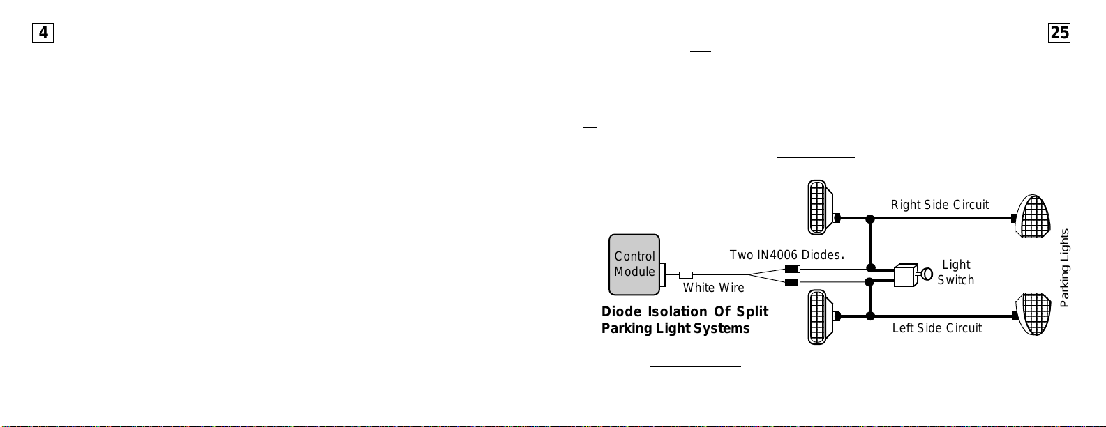
NOT connect the White wire directly to the vehicle’s headlights. An external relay is required. Vehicles having a split parking
light system must be diode-isolated,
with two IN4006 diodes as shown:
Right Side Circuit
Control
Module
Diode Isolation Of Split
Parking Light Systems
20-Gauge Orange Wire:
Connection If Desired.
tive auxiliary output which may be used to operate a starter motor "Anti-Grind" relay, which
Two IN4006 Diodes.
White Wire
The function of the Orange wire is to provide a 500mA Nega-
Light
Switch
Left Side Circuit
( - ) Anti-Grind Output
Parking Lights
Page 5
existing keyless entry or alarm system to activate the remote start operation. If the
4
4
4
4
4
4
4
4
4
Pink/Black wire receives a Negative pulse, the unit will start the vehicle's engine,
provided that all safety circuits are in the proper status. After the engine has been started
by remote control, another Negative pulse on the Pink wire will turn the unit off, stopping
the engine.
The Pink/Black wire can be connected to an available auxiliary output of an existing Remote Security System, and the unit's remote control may also be used to activate the
remote start operation.
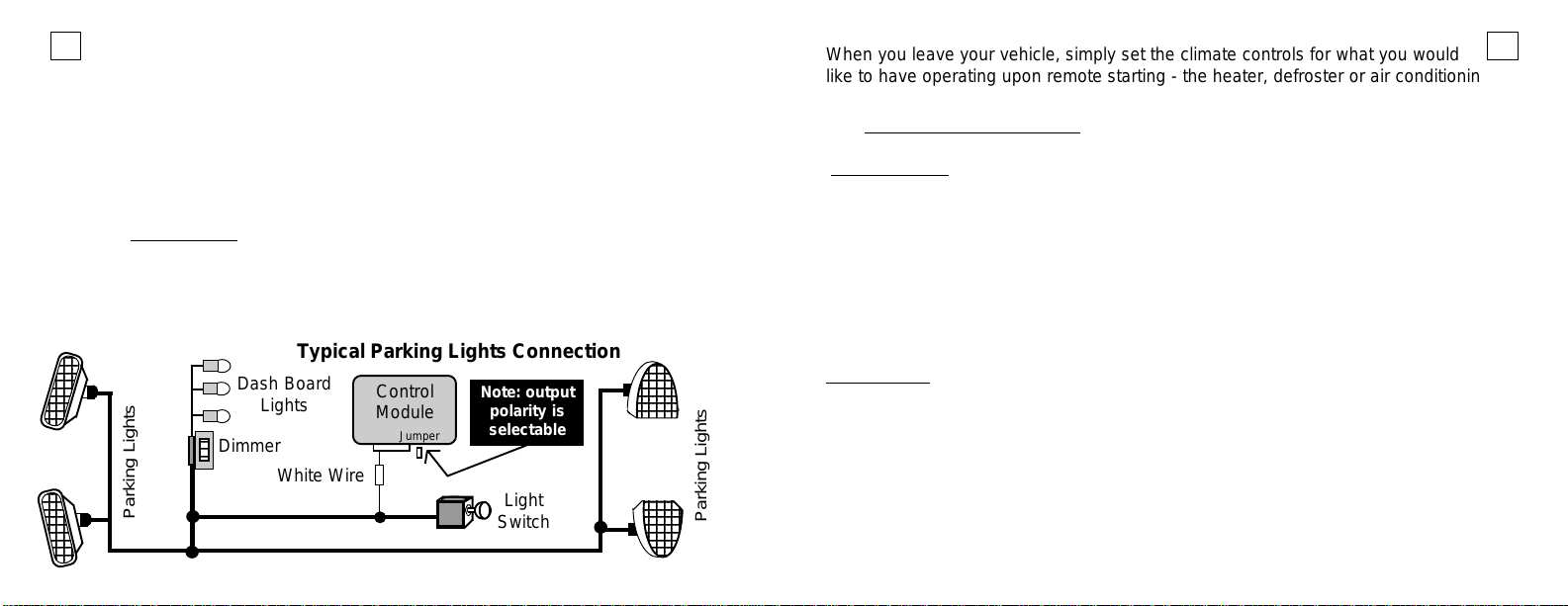
18-Gauge White Wire:
Connection Recommended.
The White wire is a programmable output to the
( +/- ) Parking Light Output
vehicle’s exterior parking lights to visually confirm system operations; +12 Volt or - Negative output may be selected by the Black jumper next to the doorlock port. Connect the
White wire to the vehicle's 12 Volt parking light circuit as shown in the accompanying
Typical Parking Lights Connection
Dash Board
Lights
Dimmer
White Wire
Parking Lights
Control
Module
Jumper
Note: output
polarity is
selectable
Light
Switch
23
23
23
23
23
23
23
23
23
Parking Lights
When you leave your vehicle, simply set the climate controls for what you would
524
like to have operating upon remote starting - the heater, defroster or air conditioning.
Upon entering the vehicle place the ignition key in the switch and turn it to the "On" posi-
and then deactivate the unit. Do not turn the key to the "Start" position!
tion,
Deactivation
• Stepping on the brake pedal will turn the engine off.
• To stop the engine by remote control, simply press the same button(s) used to start it.
• Otherwise, after the preset programmable time the unit will turn the engine off.*
• Opening the hood will turn the engine off. If the hood is open when an activation attempt
is made, the unit will only flash the parking lights 4 times, but will not start the engine.
• Pressing the Valet Switch will also stop the engine.
* The preset engine running time is 10 minutes, and 20, 30 and 40 minutes are optional.
Valet Mode
The unit may be placed into a “valet mode” which prevents the remote start feature
from being activated. Valet Mode should always be used when you do not wish for the
remote starter to be operated, such as when you have your vehicle serviced or leave it with
someone else. The Valet Switch, a small push-button, is used (check with the installer for
the location of this switch).
• At any time simply press the Valet Switch for 5 seconds; the Status Light will light steady,
to indicate Valet Mode, and stay illuminated continuously while the system is in Valet
Mode.
Page 6

Once the unit is in Valet Mode, an attempt to remote start will instead be ac-
6 23
knowledged by the parking lights turning on, then flashing rapidly, then 3 slow
flashes, but no engine starting attempt will occur.
• To turn off Valet Mode, simply press the Valet Switch until the Status Light turns off, and
the parking lights flash once to confirm exiting valet mode.
Programming Transmitters
factory alarm system. Connect the Yellow/Green wire to the wire in the vehicle
which is connected to one of the doorlock key cylinders. The typical OEM alarm
has an electrical switch in the key cylinders which switches -Ground when the key unlocks
the door. This wire can usually be located in the vehicle in either kick panel area, in the
wiring harness which is routed into the cab from the door. The Yellow/Green wire has a
-Ground pulse whenever the unit has an unlock output or its remote start operation is
activated.
The unit can be operated by additional transmitters, up to four total. Additional or replacement
transmitters must be programmed to operate the unit.
• Have present all of the transmitters which are to operate the unit. Whenever a
transmitter is programmed to the system, any existing ones are automatically erased for
security. Therefore, all of the transmitters which are to operate the system must be
programmed at the same time.
1) Turn the ignition key “On” (and leave it “on”).
2) Within 7 seconds press the Valet Switch 5 times.
The parking lights flash once, and the system Status Light turns on steady.
3) Within 15 seconds press the first transmitter’s button.
The unit will acknowledge the transmission by momentarily turning off the
Status Light, and flashing the parking lights once.
• Another transmitter to program? Go to step 4.
• Only needed to program the one transmitter? Allow the unit to exit programming mode.
20-Gauge Yellow/Red Wire:
Connection If Needed.
the vehicle is equipped with a Retained Accessory Power circuit, this output can be used to
“spike” the door pin switch wire, which will turn off the Retained Accessory Power circuit.
To arm a factory alarm after remote start engine run stops, connect the Yellow/Red wire
to the vehicle's factory arm wire. This wire will show Negative polarity when a key is held in
the "lock" position in the door key cylinder. This wire can usually be located in either kick
panel, in the wiring harness from the door, as it is routed between the door key cylinder and
the factory alarm.
To use this wire to turn off Retained Accessory Power, locate a vehicle wire within the
door or doorjamb which shows Negative when the door is open. Should such a wire be
found which is positive, a relay is needed to reverse the Yellow/Red wire’s Negative output
to Positive. The Yellow/Red wire produces a Negative pulse output whenever the system
turns off the engine after it has been remotely started.
20-Gauge Pink/Black Wire:
Connection If Needed.
This output may be used to arm a factory-installed alarm, or, if
( - ) Start Activation Input
The Pink/Black wire allows for alternative devices such as an
( - ) OEM Arm Output
Page 7

1) Connect the Black/Yellow wire to the
22 7
engine compartment, although in many cases it may also be located inside the vehicle. To use a multimeter to verify the correct tach wire, set it for AC Volts scale. The
correct wire will read 1 to 6 volts AC at idle, and will increase with engine speed.
2) Switch the selector slide switch on the unit’s control module to the right toward
the 12-pin secondary harness (see diagram or the markings on the control module).
3) Adjust the tach signal by starting the engine and turning the right adjustment screw on
the control module slowly clockwise until the indicator LED lights solid.
4) Test the operation by remote starting and checking that the indicator LED slights solid.
The starter engagement is long enough for the engine to start, but without grinding. If
needed adjust the crank time by turning the adjustment screw clockwise for more signal
sensitivity and counterclockwise for less.
vehicle's tach wire, which is found in the
4) Within 15 seconds press the next transmitter’s button.
The Status Light turns off and the parking lights flash once.
Repeat this action for each remaining transmitter.
Exiting Transmitter Programming Mode: Simply allow the unit to time out of the
programming mode, by not transmitting for 15 seconds; or, turn the ignition “Off” to exit
immediately.
The unit indicates its exit from programming mode by turning off the Status
Light. If it is allowed to time out, the ATV display shows the number of operating
transmitters for 10 seconds afterward.
20-Gauge Green/Red Wire:
Connection If Needed.
engines, operates only if programmed (feature #13) and is also polarity-programmable.
Connect the Green/Red wire to the wire in the vehicle which powers the glow plugs, or the
wire which illuminates the “Wait To Start” light on the instrument panel. When connected,
the unit will not engage the starter if the Green/Red wire has +12 Volts; in other words,
using this wire simply delays the unit’s engagement of the starter. If the “Wait To Start”
light in the vehicle has a Negative switching circuit, change the position of the White “Glow
Plug +/- Select” Jumper on the module to reverse the Green/Red wire’s polarity input.
The Green/Red wire allows the unit to be used with diesel
20-Gauge Yellow/Green Wire:
Connection If Needed.
If needed, the Yellow/Green wire allows the unit to disarm a
( +/- ) Glow Plug Input
( - ) OEM Disarm Output
Page 8

8 21
Installation
It is highly recommended that this system be professionally installed, as the sophistication
of the modern automobile and the complexity of this type of product installation is often
beyond the abilities of most do-it-yourselfers. The remainder of this booklet is comprised
of the Installation instructions, which includes the programming of features.
20-Gauge Black/Yellow Wire:
Connection Required.
lizes two different methods of monitoring the vehicle during the remote starting process.
Consider both methods before selecting one to use, and then connect the Black/Yellow
wire accordingly. Either connection method must be performed at the completion of the
installation, after all other wiring connections are made.
The Black/Yellow wire is the engine detect wire. The unit uti-
Engine Detect Input
Programming Features
The unit has 5 “programmable features” which are “installation”-related, in that they set
parameters, or make allowances, for certain conditions which may be set by the vehicle
the system is installed in, or by the remote start activation means. There is only one
programmable feature, feature #1 “Engine Run Time”, which is of any benefit or interest to
the vehicle owner or system user. Otherwise, the programmable features should not be
changed after installation.
# FEATURE DEFAULT OPTION
#
1 Engine Running Time 10 Minutes 20, 30, 40 Min.
#
2 Starter Cranking Time .5 Second .75, 1.25, 1.5 Sec.
#
3 Single or Double Pulse Activation Single Double
#
4 Gasoline or Diesel Engine Gasoline Diesel Monitor, 10, 20
#
5 Reset All Features To Default
1 brake
pedal press
Press brake pedal 1 time to reset
all features to the default setting
2; 3 or 4 brake
pedal presses
Smart Start sensing is more commonly used, for its ease of installation. The unit as
received has Smart Start selected. Smart Start “reads” the vehicle’s battery voltage level
via the Black/Yellow wire to determine engine running status. To use Smart Start:
1) Connect the Black/Yellow wire to constant “Battery” 12 volts. This may done at the
ignition switch harness, or at the battery itself for better sensitivity.
2) Switch the selector slide switch on the unit’s control module to the left toward the
module corner (see the wiring diagram and the markings on the control module).
3) Adjust Smart Start by starting the engine and turning the left adjustment screw on the
control module slowly clockwise until the indicator LED starts flashing. Turn the adjustment until the LED is flashing in a consistent and regular manner.
4) Test the operation by remote starting and checking that the indicator LED shows the
same consistent flashing (good voltage signal learned), and that the starter engagement is long enough for the engine to start, but without grinding. Turn clockwise for
more crank time and counterclockwise for less crank time.
Tach Wire sensing is generally more reliable, and preferable in cases were the engine
normally starts inconsistently, or is hard to start . With this method the Black/Yellow wire
reads the engine speed (tach) information directly from a wire in the vehicle. To use the
Tach Wire method:
Page 9

20
18-Gauge Black Wire:
Connection Required.
ground. A recommended connection is to an existing machine-thread bolt, either in the
driver's kick panel, steering column area or a major structural member behind the dash.
Small dash braces are not adequate, and the area must be clean, bright metal.
Connect the Black wire to a very good, clean chassis
20-Gauge Red/Black Wire:
Connection Required-
safety feature which disables the unit whenever the brake pedal is pressed. Connect the
Red/Black wire to the brake switch wire which shows +12 Volts when the brake pedal is
pressed. The brake switch is typically located above the brake pedal, and usually mounted
to the brake pedal support bracket. Make this connection securely for long-term reliability,
and thoroughly test the operation of this circuit.
The Red/Black wire must be connected. It is part a critical
20-Gauge Blue Wire:
Connection Required-
wire must be connected. This prevents operation of the unit if the hood is open. The Blue
wire’s second function is being a sensing wire to trigger the alarm, if the unit is armed.
Carefully install the included pin switch so that it is open (pin down) when the hood is shut
and closed (pin up) when the hood is open. Connect the Blue wire to the pin switch and
carefully route this wire through the firewall, using an added or existing grommet, avoiding
any hot or moving parts. Instead of using a pin switch to monitor the hood's open or shut
status, an Omega AU-46 Mercury Tilt Switch may used. Connect one of the AU-46's wires
to Negative Chassis Ground and connect the remaining wire to the Blue wire.
The Hood Safety Switch must be installed and the Blue
System Ground
( + ) Brake Input
( - ) Hood Input
How to program features:
1) Turn the ignition key “On”, then “Off”.
2) Within 7 seconds press the Valet Switch 5 times.
The Status Light will flash twice, then turn off .
The parking lights flash twice, and then stays on while in programming mode.
3) Select the feature to be changed by pressing the Valet Switch the same number of times
as the feature number (
The Status Light will flash the same number as the Valet Switch presses just
entered. The parking lights will flash off the same number, then come back on.
Count the number of flashes to confirm that the desired feature has been
chosen (if needed, reenter the Valet Switch presses).
4) Once the feature has been confirmed, press the brake pedal 1 time for the first, default
setting, choice; or press the brake pedal 2, 3 or 4 times to select the second, third or
fourth settings (
The Status Light will flash on the same number of brake presses, and the parking
lights will flash off the same number. Once these flashes occur, the feature is set.
• More features to program? Go to step 5.
• Only needed to program the one feature? Allow the unit to exit Programming Mode.
5) Select another feature by again making a new entry of Valet Switch presses
(repeating step 3) and again setting the newly chosen feature with the brake pedal (as in
step 4).
example: feature #3 = 3 presses
feature #3 only has two settings; see chart on previous page
).
9
).
Page 10

Exiting Programming Mode:
10
Simply allow the unit to time out of Features Programming Mode by not performing any programming actions for 15 seconds; or, turn the ignition “On” to immediately
exit the programming mode.
The unit indicates its exit from Features Programming Mode with 2 short and 1
long Status Lights flashes and the parking lights turning off.
About the Programmable Features
Of the five Programmable Features, four are strictly “installation”-related, and one is “operational” in nature. Installation-related features adapt the unit to certain vehicle situations; these are to be utilized at the time of the installation only.
#
Only Features
• Feature #1 is “Engine Running Time”. When it remotely starts the engine, the
run time before automatic shut-off is adjustable. A 10 minute run time is the factory
setting, with options of 20, 30 or 40 minutes. When programming press the brake pedal
1 time for the default-set 10 minute run time; or press the brake 2 times for 20 minutes;
3 times for 30 minutes; or 4 times for 40 minutes.
• Feature #2 is “Starter Cranking Time”, which sets the base starter cranking time
for the Smart Start voltage sensing engine detection method (page 34). When using
Smart Start, a longer st arter cranking time may be used for engines which do not st art on
the first remote start attempt. Programming choices are: .5 second (1 brake press, the
default setting); .75 second (2 brake presses); 1.25 second (3 brake presses); and 1.5
1 has a “daily use” benefit to the vehicle operator:
22 Gauge Blue Wire:
500mA ( - ) Ignition Output
Connection If Needed.
This 22 gauge Blue wire is a
500mA Negative output,
which has the same
operation as the
12 gauge Blue
Ignition output.
NOTE: If an
additional Accessory output is
needed, use the
programmable
built-in relay (Yellow/Green wire).
Red
3-pin
Harness
Wiring Connections - 12 Wire Harness
NOTE: On the 12
Wire Harness, the
Optional
Relay
Green Wire
Red Wire
Blue Wire
Optional
Relay
20-Gauge Gray Wire:
20-Gauge Brown Wire:
85
85
30
30
86
87a
87
86
87a
87
is NOT Used
is NOT Used
To Additional
Starter Circuit
Fused
constant
12 Volts
To Additional
Ignition Circuit
Fused
constant
12 Volts
.
19
.
Page 11

18
Accessory
Jumper
Ignition #2
Starter
Programming the Yellow/Green Wire
operation: Locate and open the small access panel
on the top of the control module case. Place the
Jumper as shown on the pins below the removable
panel on the control module. The factory setting is
the center “Ignition #2” position.
Wiring - 3 Wire Connector / Satellite Relay Port
The Red satellite relay port can be used, if needed, to configure optional relays to energize
additional Ignition or Starter circuits, and Omega OEM security bypass interfaces also plug
into this port. Prewired dual relay sockets are available, and a plain 3-wire harness is
provided to use this port.
22 Gauge Green Wire:
Connection If Needed.
basically the same operation as the 12 gauge Green Starter output wire. If two or more
Starter wires are present in the vehicle an optional relay is needed, connected to satellite
port Green wire as shown in the diagram.
This 22 gauge Green wire is a 500mA Negative output having
22 Gauge Red Wire:
Connection If Needed.
power the relay's coil only- DO NOT use this Red wire for the optional relay(s) power
input (pin 87).
The Red wire supplies constant 12 Volts that can be used to
500mA ( - ) Starter Output
( + ) Output For Optional Relay Coil
second (4 brake presses).
11
• Feature #3 is “Single or Double Pulse Activation”. The “Double Pulse”
option allows the unit, in certain vehicles, to activate remote starting by
locking the vehicle doors two times with the original keyless entry transmitter. Exact
operations and vehicle suitability varies; consult with the installer for specific details.
• Feature #4 is “Gasoline or Diesel Engine”. When programming, press brake pedal
once for the “Gasoline” setting. Diesel engines have three options: pressing the brake
twice selects “Monitor Glow Plug Wire”, by which the unit delays engaging the starter
until its glow plug input wire detects the glow plugs turning off; and two preset delay
periods before starter engagement: 10 seconds (press brake 3 times) and 20 seconds
(press brake 4 times).
• Feature #5 is “Reset”, and returns all Programmable Features to their factory default
settings. To do this, enter programming mode, select Feature #5, and press the brake
pedal once. The unit will acknowledge resetting the features turning off the parking
lights, flashing the Status Light once, and then immediately exiting programming mode
with the normal confirmation of 2 short and 1 long St atus Light flashes and turning off the
parking lights.
Note: When a Programmable Features Reset is used, any feature which needs to be in
a setting different from the default setting will have to be reprogrammed.
Page 12

12 17
Installation Instructions
After reading this manual, start the installation by affixing the WARNING DECAL to a visible area in the engine compartment!
Do not attempt to install this Remote Car Starter into a manual transmission
vehicle! Doing so could cause serious property damage, personal injury,
and will void all warranties!
Be aware of, and avoid, any airbag circuitry! Due to the fact that an installer
may not be in a normal, upright seated position, severe injury may occur in
an accidental airbag deployment!
The use of a Digital Multimeter (DMM) or Volt-Ohm Meter (VOM) instead of a
standard testlight is required. This can greatly reduce the risk of an accidental airbag deployment or on-board computer damage.
Battery gases are explosive! Avoid sparks and do not smoke while working
near the vehicle's battery!
Always protect wires routed through the firewall from sharp metal edges and
the 3-pin Red port to energize the second Starter wire.
Note: If a security system is present which utilizes a starter interrupt circuit,
the Green wire must be connected to the Starter Motor side of the interrupt.
12-Gauge Yellow Wire:
Connection Required
as “Primary Ignition”). This wire will show +12 Volts when the ignition key is in the "Run"
and "Start" positions and no voltage in the "Off" and "Accessory" positions. This wire is
found in the ignition switch wiring harness.
Note: If two Primary Ignition wires are present, use the Yellow/Green wire for the second,
or configure an optional relay to the 3-pin Red port.
.
Connect the Yellow wire to the vehicle's Ignition wire (also known
12-Gauge White Wire:
Connection Required
circuit supplies power to the Heat, Ventilation and Air Conditioning (HVAC) system. This
wire will show 12 Volts when the ignition key is in the "Run" and "Accessory" positions and
No voltage in the "Start" and "Off" positions. The connection point for this wire is also found
in the ignition switch wiring harness.
.
Connect the White wire to the vehicle's Accessory wire. This
Ignition Output
Accessory Output
hot parts of the engine! Always fuse positive wires at their source!
Installation Considerations: This entire booklet should be read before starting the
installation. An understanding of which control module wires are to be used and their
functions is essential. Installations will vary from car to car, as some control module wires
are required, while others are optional. Before starting the installation, it should be deter-
12-Gauge Yellow/Green Wire:
Connection If Needed
programmed to operate as an Ignition output, Accessory output or Starter output. As received, it is programmed as an Ignition #2 output. This wire may be used in cases where
the vehicle has more than one of any of these three circuits.
.
The Yellow/Green wire is an additional output which can be
Programmable Output
Page 13

16 13
Receiver Module:
The unit has a plug-in window mount Receiver Module. Optimum performance is
obtained by mounting this module high and unobstructed on the vehicle’s glass, such as
the windshield behind the rearview mirror. Make sure the glass surface is clean and free
of dust, grease, or debris. Peel the backing off of the adhesive tape and affix the Receiver
Module. Carefully route the receiver’s 3-wire ribbon cable to the control module; plug the
cable into the Black 3-pin port on the rear of the module
Wiring Connections - 6 Wire Main Harness
(Two 12-Gauge) Red Wires:
Connection Required
must supply adequate amperage. The most common sources are the battery (+) terminal
or the ignition switch wiring harness. Good reliable connections and use of the included
fuses are a must. Note that some ignition switches have the electrical switch as part of the
mechanical switch; others have the electrical switch lower on the steering column and
connected to the mechanical switch by a linkage. The ignition switch wiring harness is the
best source for these wires, and the Starter, Ignition #1 and Accessory wiring connections.
.
Connect both Red wires to constant 12 Volts. The source used
12-Gauge Green Wire:
Connection Required
will show +12 Volts only when the ignition key is in the "Start" position. This wire is also
found in the ignition switch wiring harness. Some vehicles have a second Starter wire
known as a "Cold Start" wire. When this is encountered, two options are available: program
the Yellow/Green wire as a second starter output, or use an optional relay configured to
.
Connect the Green wire to the vehicle's Starter wire. This wire
Constant +12 Volts Input
Starter Output
mined which control module wires will be used. Most installers will list these
wires, then "map out" the installation by locating and noting the target wires in
the vehicle. This will also determine the best location for the unit’s control module,
which is mounted
The remote starting unit duplicates the actions that occur within the ignition switch
when you use your key to start the engine. Because of this, most of the main wiring
harness connections will be made at the ignition switch harness. The ignition switch wires
usually are high amperage circuits, which means that high reliability connections must be
made- soldering of all connections is recommended.
Caution!
low or Red tubing or sleeves. Do not use a standard test light, as it can deploy an airbag or
damage on-board computers and sensors.
Avoid the Airbag circuit!
upon completion of the installation.
Especially avoid any harness or wires encased in Yel-
Main Module:
The Main Module should be mounted in a location close to the ignition switch (where
many of the wiring connections are made); typically, hidden behind the driver’s side
dash.
Valet Switch and Status Light:
Carefully select locations in which the Valet Switch may be easily reached, and the Status
Light may be easily seen, by the driver. Both locations will need clear space behind the
panel. Drill a 15/64” hole for the Status Light, and a 17/64” hole for the Valet Switch. Mount
these items and carefully route their wires to the Main Module.
Page 14

14
Yellow/Green:
Programmable
Output
Battery
Red & Red:
(+) 12 Volts
+
Starter
30 Amp
30 Amp
Green:
Starter (+)
Parking Lights
WIRING DIAGRAM
OPTIONAL
Relay For
Anti-Grind
Yellow:
Ignition (+)
White: Parking
Light Output
Orange: (-) Output When
White:
Accessory (+)
Light Switch
Activated
Ignition
Switch
Pink/Black:
(-) Start
Activation
Hood Pin
Switch
Blue:
(-)
Hood
Switch
Green/Red:
Glow Plug Input
Black/Yellow:
(Tach Wire)
To Coil
Red/Black:
Brake (+)
Gray: NOT USED
Brown: NOT USED
(Smart Start)
?
To Battery +
10 Amp
Yellow/Green:
OEM Disarm
Yellow/Red:
OEM Arm
Smart Start
Tach Wire
Black:
(-) Ground
Tach
Wire
Adjust
Smart
Start
Adjust
Adjustment
LED
Valet
Switch
SMART START /
TACH WIRE
YELLOW/RED = OEM ARM - OUTPUT
BLACK/YELLOW = ENGINE DETECT INPUT
RED/BLACK = BRAKE + INPUT
YELLOW/GREEN = OEM DISARM - OUTPUT
GRAY = NOT USED
BLUE = HOOD - INPUT
ORANGE = ANTI-GRIND - OUTPUT
PINK/BLACK = START ACTIVATION - INPUT
BROWN = NOT USED
GREEN/RED = GLOW PLUG +/- INPUT
WHITE = PARKING LIGHT +/- OUTPUT
BLACK = CHASSIS GROUND
PARKING LIGHT PROGRAM JUMPER
GLOW PLUG PROGRAM JUMPER
SATELLITE RELAY PORT
RED = +12V INPUT
YELLOW/GREEN = PROGRAMMABLE + OUTPUT
YELLOW = IGNITION + OUTPUT
RED = +12V INPUT
WHITE = ACCESSORY + OUTPUT
GREEN = STARTER + OUTPUT
SWITCH
Receiver
15
Unit
Status
Light
(page 17)
RECEIVER PORT
VALET SWITCH PORT
Program Jumper inside case below removable door
STATUS LIGHT PORT
 Loading...