

Page 1

User Manual
3 MegaPixel CMOS Color Camera
for Light Microscopy
SC30
Page 2

Any copyrights relating to this manual shall belong to Olympus Soft Imaging Solutions GmbH.
We at Olymnpus Soft Imaging Solutions GmbH have tried to make the info rmation co ntain ed
in this manual as accurate and reliable as possible. Nevertheless, Olympus Soft Imaging
Solutions GmbH disclaims any warranty of any kind, whether expressed o r implied, as to an y
matter whatsoever relating to this manual, including without limitation the merchantability or
fitness for any particular purpose. Olympus Soft Imaging Solutions GmbH will from time to time
revise the software described in this manual and reserves the right to make such changes
without obligation to notify the purchaser. In no event shall Olympus Soft Imaging Solutions
GmbH be liable for any indirect, special, incidental, or consequential damages arising out of
purchase or use of this manual or the information contained herein.
No part of this document may be reproduced or transmitted in any form or by any means,
electronic or mechanical, for any purpose, without the prior written permission of
Olympus Soft Imaging Solutions GmbH.
Windows, Word, Excel and Access are trademarks of Microsoft Corporation which can be
registered in various countries. Adobe and Acrobat are trademarks of Adobe Systems
Incorporated which can be registered in various countries.
© Olympus Soft Imaging Solutions GmbH
All rights reserved
Printed in Germany
SC30_EN_07April2009
Olympus Soft Imaging Solutions GmbH, Johann-Krane-Weg 39, D-48149 Münster,
Tel. (+49)251/79800-0, Fax.: (+49)251/79800-6060
Page 3

Contents
The SC30 Camera............................................................................ 5
Image Acquisition Software getIT ................................................. 7
Camera and light microscope........................................................ 8
White Balance ................................................................................................8
Monitor Settings for White Balance .....................................................9
Executing White Balance ...................... .... ... ... ... .... ... ... ... .... ... ... ... ... .... .9
The (GUI) User Interface of getIT................................................. 10
Acquiring and saving images ..................................................... 13
Set Input ............................................................................................14
Acquire Image ..................................................................................16
Define calibration .................................. .......................................... ...20
Apply calibration ......................................................................... ... ...23
Save As .......................................................................... .... ... ... .........24
Image Information .............................................................................25
Additional commands................................................................... 27
Open ..................................... .............................................. ...............27
Print Directly ................................ ... ... ... .... ... ... ...................................29
Print Setup... ............................ ... ... ... ... .... ... ... ...................................30
Print... .................................. .... ... ... ... ... .... ...................................... ...31
File list ...............................................................................................32
Exit .................................. ................ ............. ................ ................ ...... 33
Scale Bar, Show in Viewport ................................. ... ... ... .... ... ... ... ... ...33
Scale Bar, Burn into Image ................... .... ... ... ... .... ... ... ... .... ...............33
Delete Image .................................. ... ....................................... ... ... ...34
Image Manager .................................................................................34
Status Bar ..........................................................................................34
Standard Button Bar ..........................................................................35
About... ..............................................................................................35
3
Appendix I:
Microscope settings ..................................................................... 37
Illumination ................................ ............. ............. ............. ......... ............. ......37
Objective, Total Magnification and Useful Magnification .............................39
Appendix II:
Installing the camera .................................................................... 41
General Warnings ........................................................................................41
Before the installation ..................................................................................42
USB 2.0 interface .........................................................................................42
Installing the camera with Windows XP .......................................................44
Installing the camera with Windows Vista ....................................................52
Page 4

Contents
4
Appendix III:
In case of problems with the camera........................................... 59
Appendix IV:
WEEE declaration.......................................................................... 61
Appendix V:
EMC declaration - SC30 ................................................................ 62
Appendix VI:
RoHS declaration - SC30 .............................................................. 63
Index ............................................................................................... 64
Page 5

The SC30 Camera
The SC30 Camera
What is the SC30? The SC30 is a quick, high resolution CMOS color camera used for biomedical
and material sciences applications. It was especially developed for acquisitio ns
using light microscopy, has a special compact design, and can be connected to
all types of light-microscopes via the C-mount.
Technical data SC30
Chip Type CMOS
Chip Size Inch 1/2
Effective Area,
(H) x (V)
Pixel Size µm x µm 3.2 x 3.2
Binning Color binning 2x, 3x, 4x
Resolutions
(H) x (V)
at full resolution pixels 2048 x 1532
Color binning 2x pixels 1024 x 768
Color binning 3x pixels 680 x 512
Color binning 4x pixels 508 x 384
Frame Rate in the resp.
Analog to Digital Converter Bit 10
1)
Under the following conditions:
resolutions
at full resolution fps 10
Color binning 2x fps 28
Color binning 3x fps 37
Color binning 4x fps 49
Exposure times 61 µs - 1745 ms
PC-interface USB 2.0
Camera Mount Standard C-Mount
Pentium D 3 GHz Hyperthreading, 1 ms exposure time
mm x mm 6.55 x 4.92
1)
5
Page 6

The SC30 Camera
System
Requirements
To ensure that you can use your SC30 properly, the following system requirements for your PC and your software need to be met:
Hardware / Software
Processor Intel® Pentium D better than, or equal to, 3.0 GHz
System memory capacity
Removable data media
Operating system Microsoft Windows® XP Professional (32 Bit) SP2
Hard disk
Monitor 1280 x 1024 resolution with 32-bit video card
Interface USB 2.0 with Intel®82801DB/DBM USB2 ENHANCED
Internet browser Microsoft Internet Explorer 6.0 or higher
Intel® Xeon (DP / MP)
Intel® Core™Duo SSE2 compatible processor
512 MB
(RAM)
30 GB hard disk space
DVD-ROM
HOST CONTROLLER
Microsoft Windows ® Vista (32 Bit)
A certain minimum amount of performance will be required of the PC you use to
drive your camera if the speeds specified are to be reached in the live mode. The
hardware recommendations are based on typical systems and processors.
These recommendations can't include all of the systems, resp. hardware combinations, that are possible.
6
Page 7
Image Acquisition Software getIT
Image Acquisition Software getIT
In addition to your camera, you have also received the image acquisition
software getIT. The software offers the basic functions you need to acquire,
view, calibrate, save, load, and print images.
For more complicated tasks, you can connect your camera to a special software
environment for image analysis and management. Olympus offers you a wide
range of imaging system solutions which can be adapted to your individual
needs in many different fields of application in the areas of sciences, industry,
and medicine. They provide you with much more possibilities than getIT as they
enable integrated acquisition, processing, visualization, and analysis of images,
as well as device control, automatization, administration, networking, database
archiving, and the results documentation.
Warning Install the image acquisition software getIT before connectin g your camera to
your PC. This is necessary so that the operating system does not install the
wrong TWAIN camera driver. The TWAIN camera driver which is necessary for
using the camera is installed together with the software. See page 13 for more
information about TWAIN.
Installation of the software including the camera driver
The following step-by-step instructions outline the principles of a ge neric insta llation. You' ll find more detailed step-by-step instructions in the appendix (see
page 41). They apply for any camera.
1) Close any and all application programs.
2) Place the installation CD into your computer's CD-ROM drive.
" The setup program will start automatically - unless you have deacti-
vated the autorun function. If so, start the setup.exe file via Windows
Explorer with a doubleclick.
3) An installation wizard guides you through the entire software installation.
Simply follow the onscreen instructions and select the relevant entries. Select the camera you wish to use.
" The TWAIN camera driver which is necessary for using the camera is
installed together with the software.
4) After you have successfully installed your software, you may now connect
your camera to your PC.
" The camera driver is not signed and therefore not used automatical ly
under your operating system. So you will have to register the camera
driver with your operating system.
5) Doubleclick the getIT program symbol to start the software.
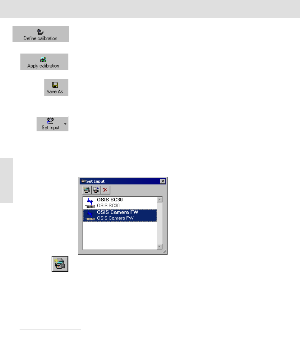
6) Within the image acquisition software click the Set Input button to check to
see if the camera driver has been integrated successfully into the software.
" Your camera driver has been integrated successfully if the camera is
shown in the Set Input dialog box.
" If your camera does not appear in the Set Input dialog box, click the New
Channel button. Select your camera from the Available devices list and
click OK. Your camera driver should now be integrated successfully.
7
Page 8

Camera and light microscope
7) Click the button with the cross located in th e upper right corner of the Set
Input dialog box to close it.
Camera and light microscope
Both the correct camera settings and the correct microscope settings are
essential prerequisites for acquiring high quality images. The most important
rules for the microscope settings are mentioned here; a more thoroug h explanation to the topic can be found in the appendix.
1) Use ND-filters to reduce the illumination intensity; do not alter the lamp
voltage.
2) Establish Köhler illumination conditions.
3) Select the appropriate total magnification and the objective for th e task in
question.
White Balance
When using white balance, the individual color channels are scaled in a way that
the white or neutral gray area of the image displayed on the monitor is displayed
correctly as white or gray. The white balance can be carried out automatically on
8
Mode of operation Select an area on the image that is uniformly gray or white. Such an area
Automatic White
Balance
Separate White
Balance
Microscope settings When you make an acquisitions prior to performing a white balance, your micro-
each image or manually for individual images.
contains an equal intensity of the three color comp onents: red , green an d blue.
White balance sets the color channels in such a way that this requirement is
satisfied in the best possible way for the area selected.
White balance is carried out on a part of the image (ROI). Your software alters
the color settings in such a way that the image area in the ROI appears as white,
resp. gray, as possible. After you have once carried out the white balance, you
can reapply it any time, also to a running live-acquisition.
For the automatic white balance, a test image is acquired under optimal ill umination conditions. The individual color channels are then set so that the acquisition also appears white or gray on the monitor. These channel settings are
saved and used automatically for all additional acquisitions.
You carry out a separate white balance on the current image. To do this, you
should select an area in the image which is, for the most part, gray or white.
scope's settings must be the same as those you use in normal practice. This
especially holds true for the filter and the lamp voltage settings. The lamp voltage
of a 12 V halogen lamp should be set to 9 V. It should, however, not be set lower
than 5 V. Use the color neutral ND-filter, should you have to reduce light
intensity.
Related Topics
Appendix I: Microscope settings 37
Page 9

Camera and light microscope
Monitor Settings for White Balance
Monitor Settings The monitor settings are decisive for the image you see on the monitor. Set your
monitor to the appropriate color temperature, should your device all ow this. To
do this, compare the image's color impression on the monitor and in the
eyepiece.
Note The col or temperature setting can be a ltered on most monitors via the monitor
menu buttons located on the monitor. In other cases, the color temperature can
be altered via the operating system.
Changing the color temperature using the operating system
1) Right click on Desktop.
" The Desktop's context menu is opened.
2) Select the entry Properties from the context menu.
" The Display Properties dialog box is opened.
3) Select the Settings tab.
4) Click the Advanced button.
" Another Display Properties dialog box is opened. The app earance an d
function of this dialog box depends on th e graphics card installed on
your system and your monitor.
" Search for a tab with the name Color or Color Management.
Note The appearance of the operating elements might differ from the one being
described here because the adaptation of the color temperature is not part of the
operating system, but rather is made accessible by the monitor manufacturer or
the graphics card being used.
5) Select a color temperature whose color impression best corresponds to that
seen in the eyepiece.
" Should your system offer a slide control with the options warm and cold,
do not alter your color temperature with these.
9
Executing White Balance
Specialized
microscopy
techniques
Transmitted Light When using the transmitted light method, look for a position through which the
Reflected light When using the reflected light method, you need a reference surface.
Related Topics
White Balance 17
It may be difficult to execute a white balance in some microscopic methods, e.g.
DIC or polarization. In these cases, execute the white balance using the bright
field method and only then change to the special methods.
light passes through the cover slip, embedding material, and microscope slide,
but not through the specimen. Should such a position not exist, remove the
sample and carry out the white balance without a sample.
Standardized gray cards are best for this. Should one not be available, you can
also use white laboratory porcelain or neutral ND-filter paper. Should your
samples contain very reflective areas, defocus your microscope when setting the
white balance.
Page 10

The (GUI) User Interface of getIT
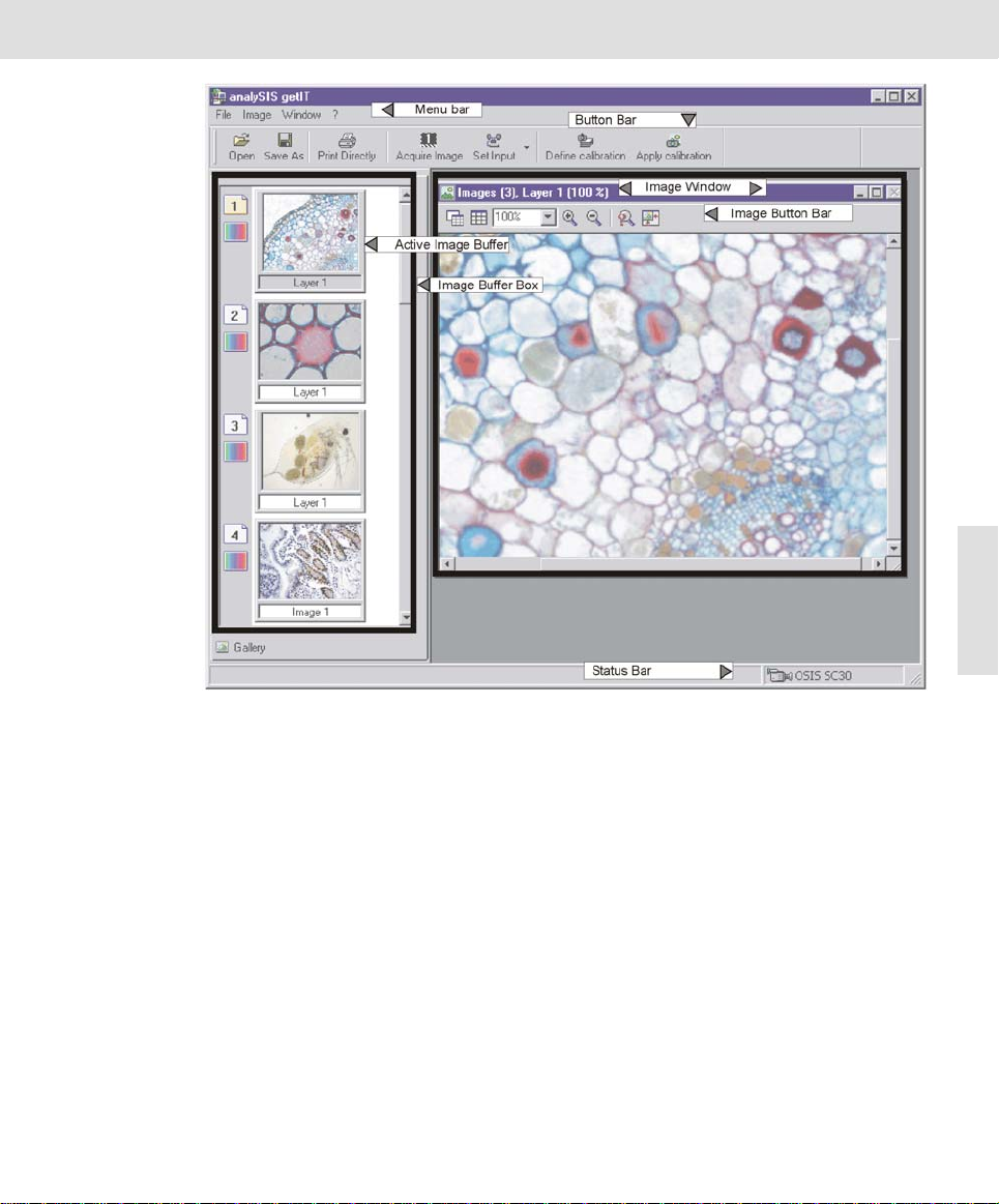
The (GUI) User Interface of getIT
GUI The graphical user interface influences the appearance of a program. It deter-
mines which menus there are, how th e individual functions can be cal led up, how
and where files, e.g., images, are displayed, and much more. This chapter
describes the basic elements of GUI.
Button bars The most important commands are linked to a button providing you with quick
Menu bar Some commands can be accessed through the corresponding menu.
Status bar The status bar contains the name of the camera and the current zoom factor of
Image buffer box Your software assigns an individual image buffer to each image. When you start
Image window
Viewport
10
Images button bar The image window contains a button bar with which you can q uickly alter the
Zoom factor The zoom factor shows you by what percentage you have zoomed the image in
and easy access to them.
the active image.
up your image acquisition software all available image buffers will b e empty.
While working with the program, you fill each individual image buffer by loading
or acquiring images. This means that many images are simultaneously accessible during any given work session. Only one image buffer however, may be
active at a time.
You can hide the image buffer box to create more room for other windows, for
example: use the [Alt + 2] shortcut.
The image window is a special window which enables you to view all of yo ur
loaded images. It is possible to view up to 9 images simultaneously. To display
them, the image window is divided up into several windows, i.e. viewports. Each
viewport can display a single image.
appearance of the images in the image window.
or out.
• An automatic zoom factor is set by default. This means that the zoom factor
is adapted to the current size of the Viewport. Alter the size of the window;
in doing so, the image will be zoomed out so that it can always be viewed
in its entirety. In doing so, the zoom factor will not be greater than 100%.
• You can enter a different zoom factor for each Viewport.
• The current zoom factor will be shown in the Viewport's header.
• When using a zoom factor of 100%, a pixel on the monitor corresponds
exactly to one image pixel.
• A fixed zoom factor does not change when you change the size of the View-
port. Thus, in certain cases, only an image segment will be displayed in the
Viewport.
• As soon as an image is larger than the Viewport, a slide control appears
which enables you to move the image in the Viewport to and fro.
• Move the image directly via Pan&Scroll. Click into the image and keep the
mouse button depressed. If the image is larger than the Viewport, the
pointer changes its form. You now move the image by moving the mouse.
Page 11
The (GUI) User Interface of getIT
11
Page 12
The (GUI) User Interface of getIT
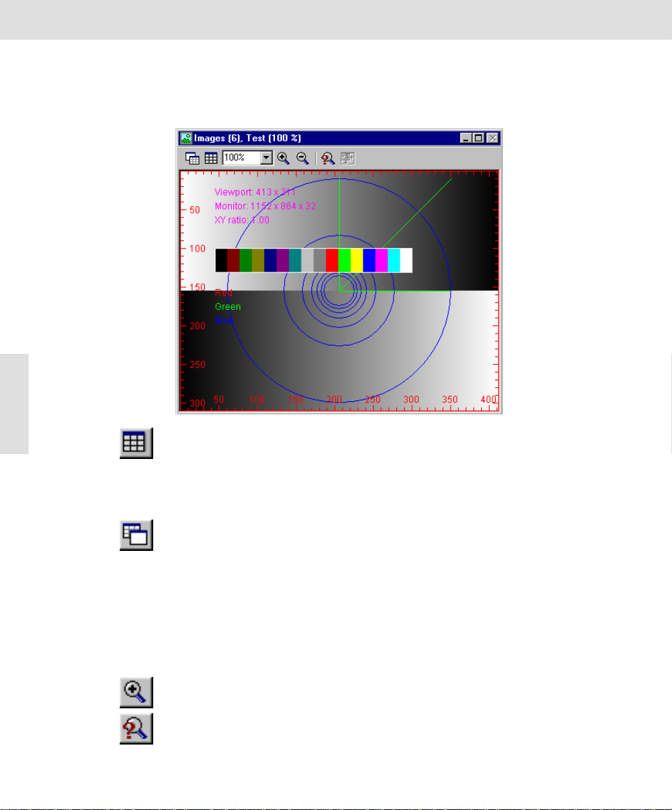
Optimizing display
1) Use the [Ctrl + Alt + T] shortcut to create a test image.
" The image window contains a button bar with which you can quickly
Press [Ctrl + Alt + T ] to
generate a test image.
Among other things, it
shows you the current
monitor resolution.
Press
[Ctrl + Alt + Shift + T] to
generate a color test
image.
The test image is auto-
matically the same size
as the active viewport.
The test image will
always be displayed at
100% zoom.
12
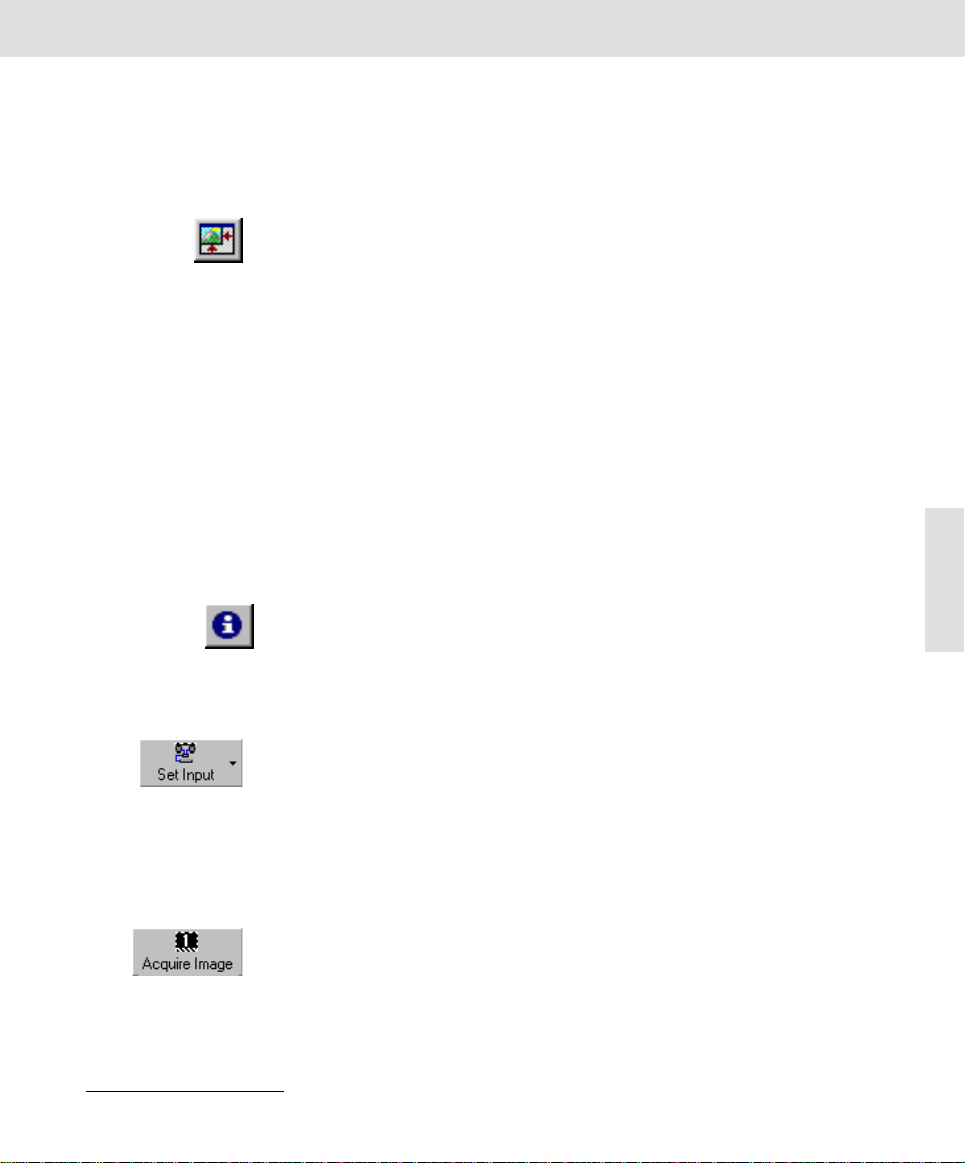
2) Click the Arrange Viewports button to redefine the number and arrange-
ment of viewports. Select a 1x2 arrangement.
" The image window will be divided up into two viewports. The test image
3) Click the Single View button to display just one image in the image window
- the active viewport image.
" The viewport arrangement and what image buffers are shown in whic h
" The Single View button changes to Tile View.
4) Select one of the entries of the Zoom Factor dropdown list - or enter any
zoom factor desired into the field directly ; e. g., 30%.
" The test image will be reduced to 30% zoom. The viewport will no longer
5) Click the Zoom In button to double the current zoom factor.
" The test image will now be displayed at a zoom factor of 60%.
6) Click the Adjust Zoom button to have the zoom factor adjusted to fit current
viewport size.
alter the appearance of the images in the image window.
is in the left viewport. Image buffers will be reassigned. Zoom factors will
be set to Auto. Though reduced in size somewhat, the entire test image
will be shown.
viewports remain unchanged.
be totally taken up by the image. Where the patterned background
starts (in the viewport) is where the image stops.
Page 13
Acquiring and saving images
• The length/width ratio of the image will not change. Unlike the automatic
zoom factor, the new zoom factor is not linked to the size of a window - i.e.,
even when you adjust the size of a window, the zoom factor stays the same.
Automatic zoom factor is set by selecting the Auto entry from the Zoom Fac-
tor list.
7) Alter the size of the image window.
8) Click the Adjust Zoom to adjust the size of the window to the size of the cur-
rent image (only available for single view).
Acquiring and saving images
This chapter describes how you can use your camera and software to acquire
images and to save them to a storage medium. A step-by-step instruction briefly
describes a typical sequence of steps. Afterwards, the commands used with all
of the options will be described in more detail.
TWAIN The image acquisition is executed with your image acquisition software, via
TWAIN. This abbreviation stands for "Technology Without An Interesting Name".
TWAIN is a standardized software interface between software programs and
image acquisition hardware such as digital cameras or scanners.
Your camera is controlled by a TWAIN driver. This allows you to make imag e
acquisitions with other application programs which have access to a TWAIN
interface. Examples for this are MS-Word and Adobe Photoshop.
Note If you are using an imaging system solution provided by Olympus instead of the
image acquisition software sent with your order, your camera will not require the
TWAIN interface. Your camera will then be controlled directly by the corresponding software and entirely incorporated into the respective procedures.
13
Related Topics
Acquire Image 16
Acquiring, calibrating, and saving images
1) Click the Set Input button to select your camera.
" This step is only necessary if also a scanner is connected to your PC or
if you manage several cameras with your image acquisition software
and would like to choose another camera.
2) In the image buffer box, use your left mouse button to click the image buffer
you would like to use to store your image.
" The selected image buffer will be highlighted in color. If it already con-
tains an image, the next image buffer will be reserved for your image.
3) Click the Acquire Image button to open the TWAIN dialog box.
" The image will be shown live in the TWAIN dialog box.
" Use the live image to optimize the camera settings. Normally you only
have to click the Auto button located in the Exposure time group. Sometimes also a white balance might be necessary.
" Click the Scan button to place the image into the selected image buffer,
thus finalizing the actual image acquisition.
Page 14
Acquiring and saving images
4) Click the Define calibration button to determine the calibration data required
5) Click the Apply calibration button.
6) Click the Save As button to save the image as an image file to a storage
Set Input
Click this button to select a camera. This is only necessary when several cameras are available and the wrong camera has been selected.
Your image acquisition software enables you to manage several cameras. Each
camera is assigned to a predefined "logical input cha nnel" wi thin th e software if the camera driver has been correctly installed. If you want to acquire an image
with a camera, the corresponding input channel must be activated.
Only one input channel can be activated. It will be highlighted in color in the dialog box's list and additionally displayed in the lower right part of the program window's status bar.
The Set Input command
14
opens the dialog box
with the with the same
name.
for the X/Y calibration of your images.
" This step is only necessary if you would like to carry out a XY calibration
of your images and the required calibration data is not yet available.
" This step is only necessary if you would like to calibrate the acquired im-
age.
" You can always calibrate an image at a later time.
medium.
Related Topics
Define calibration 20
Apply calibration 23
Save As 24
Click the New Channel button to create a new input channel for an additional
camera.
Page 15
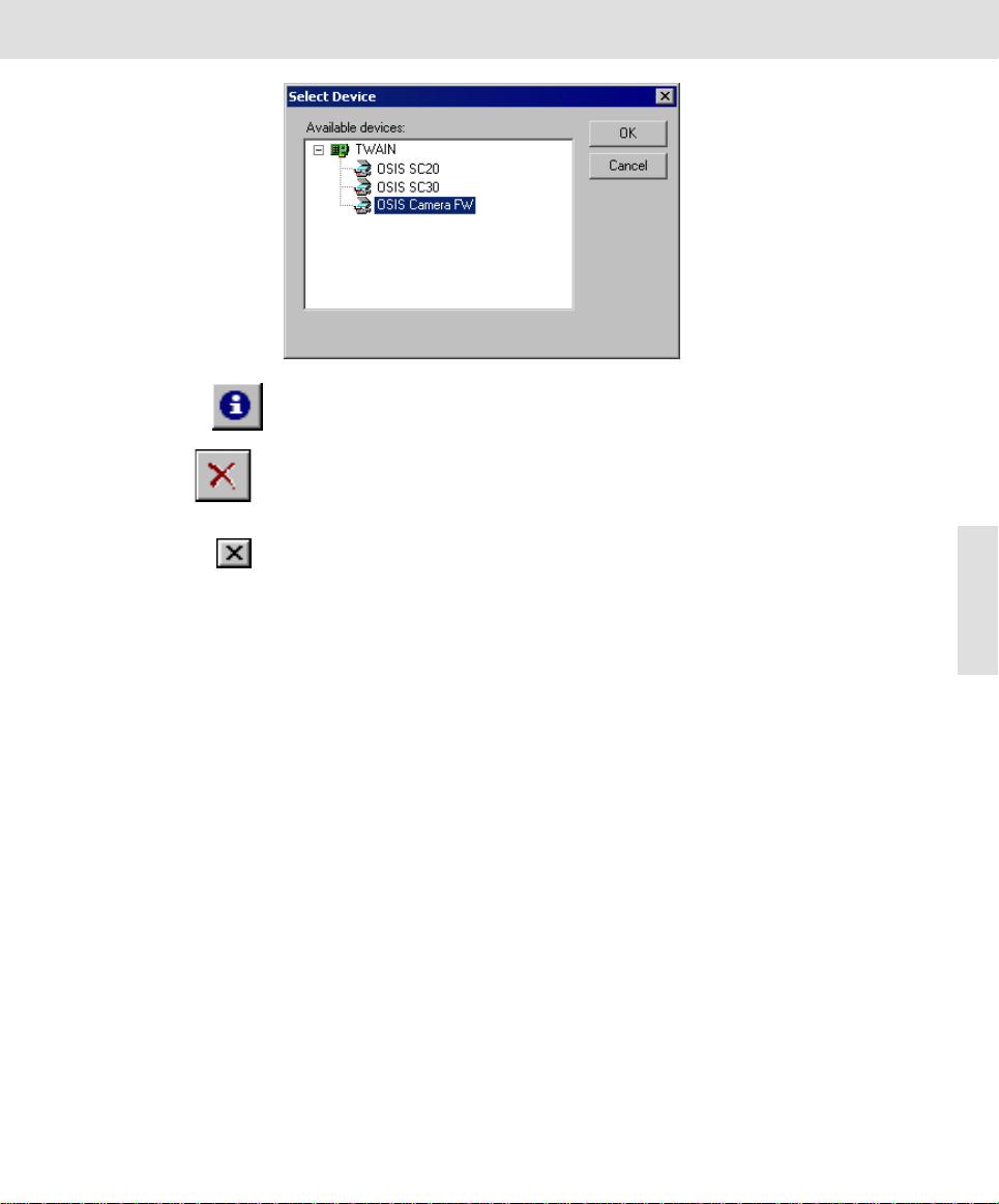
The New Channel com-
mand opens a dialog
box in which all of the
image sources, that can
be currently selected by
your image acquisition
software, are listed.
Select the desired
image source. To dis-
play all image sources,
click on the plus symbol.
Acquiring and saving images
Note You can also use the New Channel button, if you have deleted an input channel
by mistake or if the camera driver has not been integrated succe ssfully in to the
software.
Click the Delete Channel, to delete a camera's input channel. You will receive a
message if you really want to do this. If you select Yes, the input channel will be
deleted and the corresponding entry from the Set Input dialog box's list will also
be deleted.
Click the button with the cross located in the upper right corner of the Set Input
dialog box to close it.
15
Page 16
Acquiring and saving images
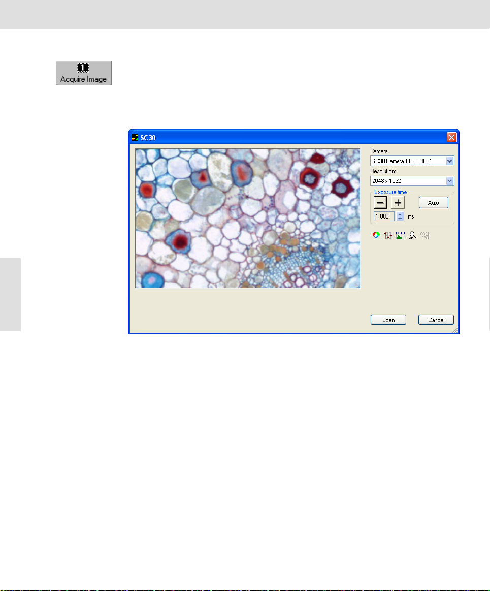
Acquire Image
Click this button to open the TWAIN dialog box for the image acquisition.
Before calling up the command, select the i mage buffer into wh ich the i mage is
to be stored. If it already contains an image, then the n ext image buffer will be
reserved for the image.
Description of the TWAIN dialog box
This is what the TWAIN
dialog box looks like for
the SC30 camera.
16
Live image You will find your camera's live image in the left side of the TWAIN dialog box.
The live image enables you to comfortably align, illuminate, and fo cus on the
object, as well as the possibility to optimally set your camera's settings.
Camera
The Camera field shows you the selected cameras with their serial numbers.
Resolution
The Resolution list enables you to select whi ch XY-resolution is to be used for
acquiring the image. A lower resolution results from combining numerous neighboring pixels ("binning") or from partially reading out the pixels ("subsampling").
That depends on the camera type. The frame rate is increased both for binning
and for subsampling. In addition the camera is more sensiti ve for binning. The
SC30 type camera is able to use resolutions of 2048 x 1532, 1024 x 768, 680 x
512 and 508 x 384 pixels, for example.
Exposure time
You can set the exposure time in the Exposure time group.
Page 17
Exposure time shorter
than 1 ms
Exposure time longer
than 125 ms
Acquiring and saving images
The exposure time required for high-quality acquisitions depen ds on the illumination, the properties of the sample, and the camera being used. The exposure
time should be longer than 1 ms and shorter than 125 ms. Should the exposure
time be outside of these limits, you can take the following actions.
The best means of increasing the exposure time is by placing neutra l density
filters in your microscope's light path. If no neutral density filters are available,
you should reduce your lamp voltage. But make sure that the voltage of a
halogen lamp doesn't drop to below 5 V. When you have reduced your lamp
voltage you will need to carry out a white balance again.
To reduce the exposure time, first remove any ND-filters that are in use. On the
microscope, you can also additionally set the pr ism or the ph ototube's mirror to
"only photo". Should the result still not b e adequate, yo u can then increase the
lamp voltage. After you have increased the lamp voltage, you should carry out
another white balance.
Click the [-] and [+] buttons to change the exposure time in pseudo-logarithmic
intervals. You can also click the arrow buttons next to the display field to alter the
exposure time in linear intervals.
Click the Auto button to automatically set the exposure time.
White Balance
Click the White Balance button to correct a tinge. During a white balance, the
individual color channels for red, green, and blue are set in such a way, that a
white or gray area of an object will be portrayed correctly in white, i.e., gray. All
of the other colors will be shown correctly, as well.
A red rectangle appears in the image. Move it with the mouse to a position as
uniformly white or gray as possible. Change the size of the rectangle by moving
the mouse and simultaneously depressing the mouse button. Rightclick to adopt
position and size of the rectangle and execute the white balance.
17
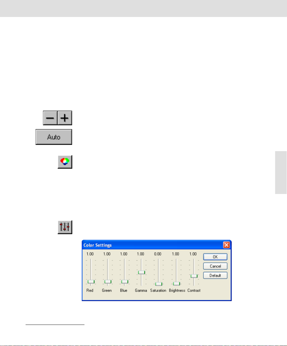
This is what the Color
Settings dialog box
looks like for the SC30
camera.
Related Topics
White Balance 8
Color Settings
Click the Color Settings button to manually alter your camera's color settings.
Based on the type of camera you are using, this may be done via numerous slide
controls.
Page 18
Acquiring and saving images
Red, Green, Blue The Red, Green and Blue slide controls can be moved from 0,00 to 10,0. The set
Gamma Use the Gamma slide control to result in a nonlinear contrast enhancement.
What is gamma? The numerical value of gamma influences how the illumination intensity on the
Saturation Use the Saturation slide control as an alternative to the slide controls of the indi-
Brightness Use the Brightness slide control to change the image's intensity. Values smaller
Contrast Use the Contrast slide control to change the image's contrast. Values smaller
18
Default Click the Default button to set all of the slide controls to a predefined defa ult
value is the factor with which the signals of the corresponding color channel are
multiplied.
CCD chip's pixels is converted into the color value of the respective pixels in the
image buffer. Please note that this also applies for the other slide controls. If
gamma equals 1, the conversion from illumination intensity into gray value i.e.,
color value is linear. A nonlinear contrast enhancement is the result if gamma is
not equal to 1. If gamma is less than 1, the light gra y values are spread more
than the dark ones. This results in an improvement of contrast in the image's light
areas. The image, in general, will become darker as a whole. If gamma is more
than 1, the dark gray values are spread more than the light ones. This results in
an improvement of contrast in the image's dark areas. The image, in general, will
become lighter as a whole.
vidual color channels. The Saturation slide control enables you to alter the color
reproduction from black and white to a maximum color saturation.
than 1 lower the image's intensity. Values greater than 1 increase the image's
intensity.
than 1 lower the image's contrast. Values greater than 1 increase the image's
contrast.
value.
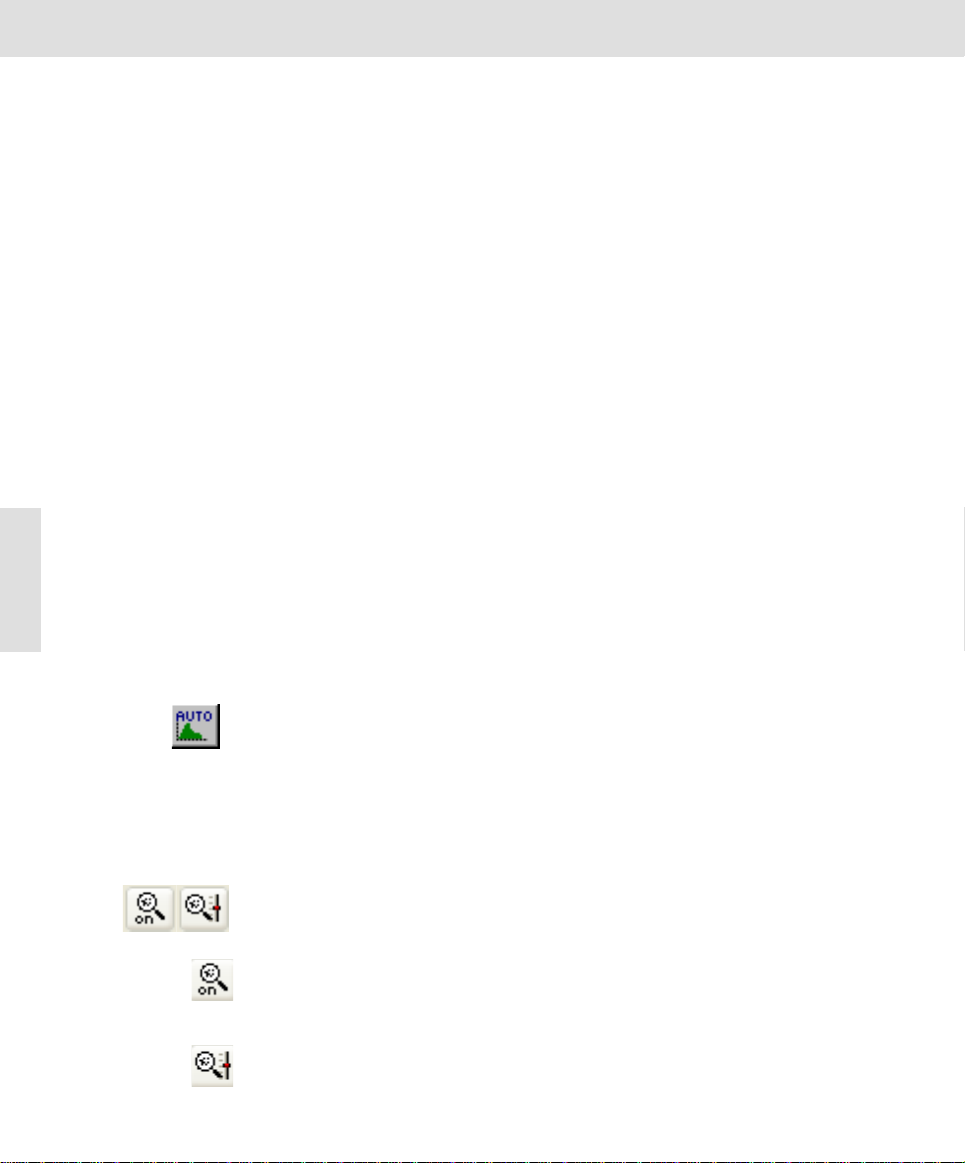
Sharpen
Filter On/Off
Sharpen
Filter
Settings
Auto Contrast
Click the Auto Contrast button, to activate or deactivate the automatic contrast
enhancement. Now the image will always be shown with enhanced contrast
onscreen no matter what the actual exposure conditions are, provided there is
no over exposure. For this purpose, the system automatically calculates two
sensible limits for displaying the intensity from the intensity distribu tion in the
image. Intensity values below the minimal value and above the maximum values
will be cut off. The intensity values in between will be spread out on the entire
dynamic range of the camera.
Sharpen filter
Use the sharpen filter to increase the sharpness using edge enhancement
already with the live acquisition.
Click the Sharpen Filter On/Off button to activate/deactivate the sharpen filter.
The manner in which the acquired image is affected by the sharpen filter
depends on the sharpen filter parameter. You can adjust this parameter by using
the Sharpen Filter Settings dialog box.
Click on the Sharpen Filter Settings button to open a dialog box where you ca n
set the sharpen filter parameter:
Page 19
Acquiring and saving images
To adjust the numerical value of the sharpen filter parameter, use the mouse to
move the slide control to the right or left. Whether the contou rs of the image
appear to be sharper or softer when you apply the sharpen filter, depends on the
position of the Sharpen filter parameter slide control.
Increasing sharpness will accentuate edges, but also brings out more image
noise. Reducing the sharpness makes the image softer. Entering a value of 0 will
result in the sharpen filter having no effect at all.
Please note that when you use the sharpen filter you not only alter the mon itor
display, but the actual image information as well. This means that when you are
planning on quantitatively evaluating your images later, you sh ould not use the
sharpen filter. Your software provides you with commands with which you can
subsequently process an image's sharpness at any time.
The Sharpen Filter Settings button is only available if the sharpen filter has been
activated.
Scan
Click the Scan button to place the image into the selected image buffer, thus
finalizing your image acquisition. The TWAIN dialog box clo ses. You can now
save the image as an image file.
Cancel
Click the Cancel button to close the TWAIN dialog box, without acquiring a n
image. Only a black image will appear in the image buffer. As an alternative, you
can cancel an image acquisition by clicking the button with the cross located at
the upper right corner of the TWAIN dialog box.
19
Page 20

Acquiring and saving images
Define calibration
Click this button to determine the calibration data required for the X/Y calibration
of your images. Such a calibration is only necessary and reasonable if you use
your camera with a microscope or with a macro stand with one or more definite
magnification ranges.
The image acquisition software enables you to calibrate images after acquisition.
Calibration means that for each magnification the width and height of an object
area is assigned to the pixel representing that ob ject area. This might be, for
example, 0,63 µm x 0,63 µm for a magnification of 5x. This calibration data varies for each magnification.
1) Place a stage micrometer under your microscope and focus.
The illustration shows a
light microscope's
micrometer.
20
2) Click the Acquire Image button to acquire an image of the stage microme-
ter.
" The image will be put into the active image buffer.
3) Click the Define calibration button to open the dialog box required to deter-
mine the calibration data.
4) Click the Calibrate... button.
" The Calibrate Image dialog box opens.
Page 21

Acquiring and saving images
5) Click the Unit... button.
" Select m (for meters) in the Basic unit list in the Set Unit dialog box.
" Select, e.g., µ in the Scale list if you wish the calibration length to be
shown in µm. Confirm by clicking OK.
6) Enter this magnification level into the Magnification field.
7) Enter the length you are using to calibrate with into the Calibration length
field.
" The distance between the scale marks 30 and 80 in the example shown
is 500 µm.
8) Select the Arbitrary option in the Calibration group.
9) Now click the Calibrate button.
" The mouse pointer will appear within the active image.
10) Position the mouse pointer at the starting point of the calibration length and
leftclick.
11) Then position the mouse pointer at the final point of the calibration length
and confirm by leftclicking. The blue line must be the exact same length as
the calibration length you entered in the Calibrate Image dialog box.
" The calibration data for the selected magnification are now shown in the
X calibration and Y calibration fields.
21
Page 22

Acquiring and saving images
12) Confirm by clicking OK.
13) Finish the calibration by clicking Close.
Description of the dialog box
22
" The Calibrate Image dialog box will be closed.
" A magnification is now available in the Define Calibration dialog box.
You will be asked whether or not you want to replace the old data with
the new ones, should data about the calibration already exist for this
magnification.
" The calibration will be directly applied to the active image.
" You can expand additional calibration data for other magnifications
whenever you like.
" To calibrate additional images based on the set calibration data, use the
Apply calibration button.
" You can view the calibration data of an image any time, by double click-
ing the image buffer to open the Image Information dialog box.
New Click the New button to create a new set of calibration data. This set of calibra-
tion data appears under the selected camera name. This is, for example, useful
if you use your camera on various microscopes.
This is how you create a new set of calibration data:
1) Click the New button.
" The DCCalib dialog box is opened.
2) Enter a name into the edit field located in the DCCalib dialog box.
" Please note: The Pixel size linked to image size check box should
always be marked. In this case, the calibratio n data are automatically
adjusted by the software when setting another image resolution.
Page 23

3) Confirm by clicking OK.
Delete Click the Delete button to delete the active set of calibration data.
Calibrate... Click the Calibrate... button to add new calibration data to the active set.
Graph >> Click the Graph >> button to show a diagram with the calibration data. Use this
diagram to check your calibration data. The diagram shows the reciprocal pixel
size versus magnification. The points should all be along one line.
Apply calibration
Click this button to calibrate the active image using the available calibration data.
Should there not be any appropriate calibration data available, use th e Define
calibration command to create the calibration data, as described starting on
page 20.
1) Acquire an image or click on the image buffer in which the image to b e
2) Click the Apply calibration button.
Acquiring and saving images
" A new entry is added to the Camera name list located in the Define
Calibration dialog box. Since there are no calibration data for this
camera, the Magnification list will be empty.
calibrated has been stored.
" The Apply calibration dialog box opens.
23
3) Select the appropriate set of calibration data from the Camera name list.
4) Select the magnification you used to acquire the image from the Magnifica-
tion list.
" In the list, you will find all of the magnifications which you defined for this
camera name using the Define calibration command.
" You may also enter a magnification which is not in the list. In this case,
the software automatically interpolates the correct calibration data.
5) Confirm the message by clicking OK.
6) Doubleclick the image buffer to open the Image Information dialog box in
order to view the calibration data.
" The Magnification, Width and Height values have now been accordingly
adapted to the calibration data.
" Only if you save the image in TIF file format, will the calibration data be
saved together with the image.
Page 24

Acquiring and saving images
Save As
Click this button to save the active image to a storage medium under a n ew file
name or path name.
Before calling up the command, select the image you would like to save from the
image buffer box.
Alternative You can also use the File > Save As... menu command or the [Ctrl + S] shortcut.
Deleting directories
and files
24
You can also additionally use the command to delete directories an d document
files. To do so, select the desired files and depress the [Del] key.
Description of the dialog box
Save in Select the drive and directory to which the document is to be saved from the
File list The dialog box shows all the files with the file extension shown in the Save as
Files of type The Save as type list contains all the file formats under which the active image
File name The File name field offers you a file name. When dealing with newly a cquired
Compression The Compression field provides yo u with the compression method required to
Save in list.
type field.
can be saved. The additional image information including calibration data is only
saved together with the image if you choose the Tagged Image Format (*.tif) file
format.
images, this would be the image name.
save images. The field is only shown for the image file formats TIF and JPG
which allow compression. The following compression methods are possible for
the image file format TIF: None, Packed Bits, JPEG 2000, JPEG or LZW.
Page 25

You can alter the compression method and quality of the images. To do so,
select either the Tagged Image Format (*.tif), JPEG (JFIF) (*.jpg) or JPEG 2000
(*.jp2) file type. Click the Options... button and open the Save Image Options dia-
log box. You will find various compression methods and JPEG quality.
Image Information
Doubleclick the image buffer to alter the name of the image, to add a comment
to an image, and to display data about the image. Except for the name of the
image this image data are only then saved when you save the image in TIF
format.
Alternative Use the [Alt + Enter] shortcut to view data about the image in the active image
buffer.
Acquiring and saving images
25
Image Name You may enter a new name for the image in the Image name field. It can be up
to 31 signs long.
The image is assigned a standard name during image acquisition, which is compiled of the name of the software, as well as a consecutive number.
File name When you load an image, the File name field will contain that image file's com-
plete path. When acquiring an image using your camera, this field will be blank
- until you have saved the image.
Page 26

Acquiring and saving images
When saving an image, your software will automatically suggest the image name
for use as the name of the file.
Warning Image name and file name are not the same. If you assign the name "Pollen
04.05.2006 Image 23" to an image, you can save the same in TIF format under
the name "04050623.tif". When you later reload this TIF image, the original
image name will appear within the image buffer.
Image buffer The Image buffer field displays the number of the image buffer currently contain-
ing the image. This number will of course change when you, for example, put the
image into another image buffer.
Frame: 1/1 The field next to the Image buffer field is not relevant for your image acquisition
software.
Memory size To calculate the amount of memory occupied by the image in your RAM, the sys-
tem multiplies the number of image pixels with the current bit depth. The memory
requirements of the image information will al so be take n in to consid eration. For
the RAM memory requirements, it does not matter if the image file has been
compressed on the hard disc or not.
File size The File size field shows you the file size of a loaded imag e file. The field is
empty directly after image acquisition.
Created The Created field shows the acquisition times for images which you acquired
with your camera. For other images, the date and time of the last modifications
made to the image are shown.
Channel The Channel field shows the name of the camera for images acquired with your
26
Magnification The Magnification field shows the selected magni fication for imag es which you
Resolution The Resolution field displays image size (in p ixels) and information de pth (bits/
Width
Height
Image intensity The Image intensity field is irrelevant for your camera.
Comment You can enter your annotations about the image in the active image bu ffer into
camera. The field does not contain any information for other images.
acquired with your camera. Use the Apply calib ration command to define the
magnification.
The magnification for images from other applications is set to 1 as a default.
pixel). The entry 1376 x 1038 x 24 means: The image width corresponds to
1376 Pi xels, the image height corresponds to 1038 Pixel, and the image can
contain 2
The Width and Height fields show the absolute measurements of th e images
which you have acquired with your camera. These values are determined using
the current image calibration.
For other images, the fields show the width and height of your images in pixels.
the Comment field.
24
different color values.
Page 27

Additional commands
This chapter describes the buttons which have not been described yet in the previous chapter, as well as the commands which cannot be accessed by a button.
Open
Click this button to load images from a data medium.
Before opening the command, select the image buffer into which the first image
is to be loaded.
Alternative You can also use the File > Open... menu command or the [Ctrl + O] shortcut.
Deleting directories
and files
Dialog boxes for loading
files are based on
standard MS Windows
dialog boxes. The dialog
box for loading images
also has a preview
function.
You can also additionally use the comma nd to delete d irectories an d document
files. To do so, select the desired files from the corresponding dialog box and
click the [Del] key.
Description of the dialog box
Additional commands
27
Look in Select the drive and directory of the desired files from the Look in list.
File list The dialog box shows all of the subdirectories and all files whose format is
Files of type You can select the desired document type from the Files of type list. The Tagged
File name Click the document file you are looking for in the file list, to copy it to the File
displayed in the Files of type field.
Image Format (*tif) image file format is set by default.
You can also select the Image Formats entry to show a list of all the files with
every image format available. All the displayed images can be opened with your
image acquisition software.
name field. You can load several documents simultaneou sly. To do so, mark a
random selection of files by depressing the [Ctrl] key and clicking on the files you
require.
Page 28

Additional commands
Preview You can view the single images to the right of the dial og box, th us allowi ng yo u
Open Open enables you to load images into a sequential image buffer.
to check which documents you want to open. To do so, click the Preview button
and select the individual image files. The selected document will be displayed in
reduced size.
Click the Preview button a second time to view the file's document properties
with various additional information. When using TIF images, the image attribute
Name gives you the image name, Created the date and time the image was
acquired or created, Resolution the image resolution in height x width (in pixels)
x bit depth, Compression the method of compression, User the name of the user
of the image acquisition software, Application the program versi on being used,
and Channel the camera with which the image was acquired.
A third click enables you to hide preview.
You can also use the commands of the drop-down menu lo cated to the right of
the button, to switch back and forth between the preview, properties, and standard view without the preview area.
[Del] Use the [Del] key to delete the selected files or directories.
Loading images stored on the hard drive
1) In the image buffer box, click the image buffer you wi sh to load the imag e
into, with the left mouse button. Select - for example - image buffer #5.
" The selected image buffer will be highlighted in color.
2) Click the Open button to load an image.
28
" The Open Image dialog box will appear.
3) Select Tagged Image Format (*.tif), the standard image format, in the Files
of type list.
" This format is the default when you open this dialog box for the first time.
4) Click the Up One Level button to move up a level in the directory structure
of your computer.
" In the field below the button bar you will find a list of all sub-folders and
documents of the file type selected.
5) Doubleclick on one of the folders listed to get a listin g of its contents - i.e.,
all subdirectories and files the folder contains.
6) Click the Preview button to view thumbnails of image files. Select the image
files one at a time.
7) Select the images you wish to load.
8) Click the Open button to load the images selected.
" The Open Image dialog box will be closed.
" The images will be loaded into successive image buffers. You will find
the first image in the active image buffer, e.g., #5. The next images can
be found in image buffers 6-9, if you have simultaneously loaded a total
of 5 images.
" The image type and image name will be shown directly in the image
buffer box. You will, for example, acquire "true-color images" when
using the SC30 camera. A true-color image consists of 224 color values
(24 Bit).
Page 29

You can view the
thumbnails of all of the
loaded images in the
image buffer box.
Use the mouse to
drag&drop images into
the image buffer
desired.
MS Explorer, a file
manager, can also be
used for drag&drop
loading.
Additional commands
Using the mouse to drag images into image buffers
1) Click the Open button.
2) Leftclick on the image file you wish to load.
3) Drag the file directly onto the desired image buffer, while keeping your left
mouse button depressed, (drag&drop).
" The image buffer will show a thumbnail of the image you have loaded.
4) Repeat the last two steps if you wish to load further images.
5) To quit loading, just click the Close button.
29
Print Directly
Click this button to quickly print a single image. The Print Image dialog box wil l
NOT open. The command always prints an image in default page layout: The
header shows the image name, the footer shows the date and time of when printing was started. The button is only available if an image has been loaded into the
active image buffer.
Page 30

Additional commands
Print Setup...
Use this command from the File menu to determine a certain printer and printer
settings as a default for your image acquisition software.
The selected printer and the corresponding settings remain for future applications using your image acquisition software.
30
Status/Type/Where/
Portrait/Landscape Select the Portrait format to print the pages vertically. Select the Landscape
Printer From the Printer group, select the Name of the desired printer from the list as
well as the corresponding properties using the Properties... button.
Name The Name list contains all of the printers installed under Windows. The printer
which has been defined as standard by Windows in the printer setting s, is the
default printer. Select the printer which you mostly use with your image acquisition software from the printer list.
The Status, Type, Where and Comment fields provide information about the
Comment
Properties... Click the Properties... button to open the dialog box with the same name. This
Paper Select the paper size and source from the Paper group.
Size/Source Select the desired entries from the Size and Source lists. The entries depend on
Format The Format group enables you to determine the page alignment.
selected printer: operating state, printer type, path name, and additional
comments.
will allow you to select the printer settings with regards to the configuration,
paper, graphics, and font. The exact appearance of the dialog box depends on
the selected printer and printer driver.
the printer you are using.
format to print the pages horizontally.
Page 31
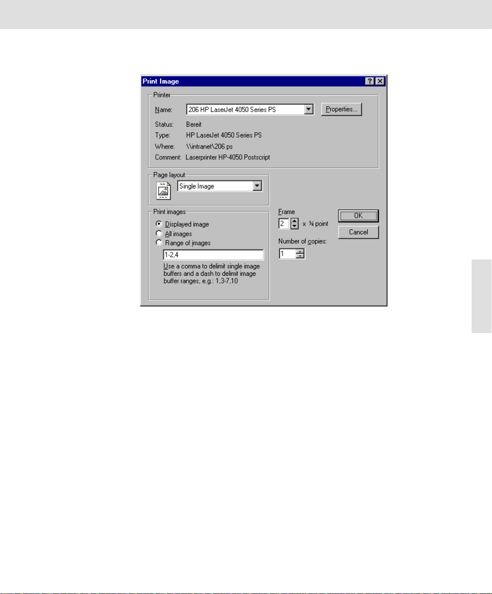
Print...
Additional commands
Use this command from the File menu to print images.
31
Printer From the Printer group, select the Name of the desired printer from the list as
Name The Name list contains all of the printers installed under Windows. When open-
Status/Type/Where/
Comment
Properties... Click the Properties... button to open the dialog box with the same name. This
Page layout The Page layout list contains the Single Image and Multiple Images entries. Here
well as the corresponding properties using the Properties... button. These settings are lost after closing the program. Use the Print Setup... command if you
want to set the printer and the corresponding properties as default for your image
acquisition software.
ing the program, the printer which has been selected as defa ult printer for your
image acquisition software in the Print Setup dialog box, is preset. The printer
selected for the previous prints will be offered for each additional print.
The Status, Type, Where and Comment fields provide information about the
selected printer: operating state, printer type, path name, and additional
comments.
will allow you to select the printer settings with regards to the configuration,
paper, graphics, and font. The exact appearance of the dialog box depends on
the selected printer and printer driver.
you can select which predefined page layout is to be used for printing. The Print
images group enables you to then decide which images will actually be printed.
Page 32

Additional commands
Two page layouts are
predefined. Print either
one or six images on a
Each image has its own
header when using
numerous images.
page.
Single Image
Multiple Images
Print images The Print images group enables you to determine which images you want to
Displayed image Choose the Displayed image option to only print the image in the active image
32
Number of copies You enter the number of copies you would like to have printed into the Number
All images Select the All images option to print all of the images in the image buffer box.
Range of images
(Option)
Frame You can enter the width of the frame which is to be displayed around each image
Select the Single Image entry when wanting to print one image per p age. The
header contains the image name, while the footer contains the date and time of
print.
Select the Multiple Images, to print 6 images on one page, respe ctively. Each
image then automatically contains a header with the image name.
print. The selected images are then printed in the page layout which you selected
from the Page layout list. In doing so, the number of pages printed will automat-
ically refer to the number of images selected. These are, for example, 3 pages,
should you want to print 3 images with the Single Image page layout.
buffer.
Select the Range of images option to print a range of images from the image
buffer box. To do so, you enter the number of the image buffers whose images
you would like to print, into the corresponding field. Each number is separa ted
by a comma. The order of the image buffers in the field corresponds with the
order in which the images are to be printed. This allows you to control the order
of several images on a page. Several consecutive image buffers can be replaced
by an interval. For example, you can write 4-7 instead of 4,5,6,7.
into the Frame field. The unit is a 1/4 point. The setting "0" means that no frame
is to be printed.
of copies field.
OK OK enables you to close the dialog box and start printing.
File list
Use the display of the path names at the end of the File menu to quickly load the
corresponding images.
The most recent images to be saved and loaded are displayed in the file list.
Click the desired file name or type in the corresponding number using your keyboard.
The file name remains even if you exit and restart the program.
Page 33

Additional commands
Exit
Use the command from the File menu to end the program.
Alternative Click the button with the cross located at the upper right edge of the program win-
dow.
Warning Save all of the loaded images you want to keep. Any unsaved images will be
deleted without prior warning.
Image in the clipboard If you have copied an image into the clipboard, you will get a message informing
you of this - if the image is larger than 768 x 576 x 8 bits. Click on Yes if you wish
to keep the image in the clipboard - it will remain available to you for other applications.
Any image of smaller size will remain available to you anyway.
Scale Bar, Show in Viewport
Use this command from the Image menu to display or hide a standard scale bar
in the image window. This setting applies to all loaded images. You will only
attain a useful scale bar after you have calibrated the image by clicking the Apply
calibration button.
Note The automatic scale bar in the viewport is not part of the image, but rather a
property of the viewport. It appears in a default size in the lower right hand corner, i.e., the size, position and font size of the scale bar does not change if you
alter the position of the image within the viewport, or if you alter the image's zoom
factor. The calibration length will always be automatically adjusted to fit the current zoom factor of the image in the viewport. You may also have the unit automatically adjusted in order to avoid excessively large or small numeric value s.
You can alternatively use the keyboard shortcut [Shift + F4] to be able to quickly
switch between views.
33
Scale Bar, Burn into Image
Use this command to irrevocably insert the scale bar into the image. In doing so,
all of the image information below the burned scale bar will be lost.
Warning Please remember that this command cannot be reversed.
Select numerous
images
What’s it for? One of the main reasons for burning a scale bar into an image is when you are
Related Topics
Apply calibration 23
A scale bar that has been burned into an image can of course no longer automatically be adjusted to fit image size because it has become a part of that
image.
You can simultaneously apply this command to numerous images. To do so,
select the desired images from the image buffer box.
preparing to export an image into another application program - e.g., MS Word which cannot read the image’s calibration data. The image ca libration remains
accessible, if the scale bar has been burnt into the image. If you want to print an
image together with its scale bar you also ha ve to burn the scale bar into the
image beforehand.
Page 34

Additional commands
Position and length The scale bar is burnt into the lower right hand corner. The length of the scale
bar corresponds to the length which is displaye d in the viewport when using a
zoom factor of 100%.
Delete Image
Use this command from the Image menu, in order to delete the image from the
active image buffer.
Alternative Activate the image buffer and depress the [Esc] key.
Why delete images? Use this command to remove images no longer required. Since the program allo-
cates space for every occupied image buffer, using this command will relieve a
considerable amount of memory. A true-color image with a resolution of 257 6 x
1932 pixels requires about 15 megabytes of RAM. MS Windows will then start
swapping memory to disk. If you are using up to o much storage your disk will
have to be active more and more often thus slowing down the reaction time of
this and other applications. By deleting images, you can relieve the corresponding amount of memory in the RAM and thus increase the speed of the program.
Warning You will not receive a warning message. The image will be lost if it has not been
saved to the hard disk.
Which images will not
be deleted?
Deleting selected
34
Delete all images If you keep the [Shift] key depressed while opening the Image menu, the com-
images
Saved files on the hard disk or other storage mediums are NOT affected.
To delete multiple images all at once, select them in the image buffer box. Press
[Shift] or [Ctrl] while selecting the images with the mouse. Now the command in
the Image menu will be called Delete Images.
mand will be Delete all Images instead of Delete Image. The contents of all buffers will be erased and the allocated memory will become available once again.
Image Manager
Use this command from the Window menu to display or hide the image buffer
box.
Alternative You can also use the [Alt + 2] keyboard shortcut.
What’s it for? You can hide the image buffer box to increase the size of the document area.
For example, you will have more room on your monitor for the image windo w
when wanting to display numerous images simultaneously.
What will happen... The command name is marked by a check mark in front of the command when
the image buffer box is displayed.
Status Bar
Use this command from the Window menu to display or hide the status bar.
What will happen... The command name is marked by a check mark in front of the command when
the status bar is displayed.
Related Topics
The (GUI) User Interface of getIT 10
Page 35

Additional commands
Standard Button Bar
Use this command from the Window menu to display or hide the standard button
bar.
What will happen... The command name is marked by a check mark in front of the command when
the standard button bar is displayed.
About...
Use this command from the ? menu to display information about your program
such as: version number, serial number, copyright, as well as system information
pertaining to your computer and your MS Windows installation.
System Info... Click the System Info... button to open the dialog box with the same name.
What’s it for? The dialog b ox contains various lists with info rma ti o n pe rtaining to your system:
image acquisition software and hardware components such as your camera. It
also contains information about your PC and operating system.
35
Use the tree view located to the left of the dialog box as if it were a table of contents: Click the "+" symbol on the left side to show the "chapter". Select an entry
to view its contents to the right.
Save Info Click the Save Info button to open the standard windows I/O dialog box. You can
then determine a path in which the contents of this dia log box is to be saved in
the "SysInfo.txt" file. Furthermore, the file "SISgetIT.ini" and additional INI and
LOG files will be saved.
Page 36

Additional commands
More Info Click the More Info button to open the System information Windows dialog box.
This enables you to take a look at the assembly and configuration of your computer, as well as your operating system's settings and components and the
loaded Microsoft programs.
36
Page 37

Appendix I: Microscope settings
Your digital camera can only achieve high image quality if the micro scope has
been optimally set. A subsequent correction to the software can never correct
deficiencies in the image resulting from faulty settings made to the camera an d
microscope.
The optical system "microscope" offers numerous setting possibilities. In order
to attain best acquisition results, the settings must be made precisely.
In spite of varying models and observation possibilities, the microscope's image
producing components are in accordance with each other.
A microscope basically consists of the optical components, objective and
eyepiece. An additionally important component is the illuminator.
This illustration clarifies
the basic assembly of
the components of a
microscope in
transmitted-light mode.
Camera
Eyepiece
Appendix I: Microscope settings
Objective
Sample
Condenser
Illumination
Lamp
Illumination
Light is a decisive medium for creating images with a microscope. As a result,
the light, i.e. illumination, plays an important role in creating the image in the
microscope.
The goal of the illumination settings is the equal distribution of light on the sample
with parallel light rays falling on the object. The illumination must be bright
enough to make all of the image details visible; however over-illumination leads
to images being too bright and low-contrast. In addition, the color of the light has
a strong impact on the sample's color rendering.
Lamp Selection The tungsten-halogen lamps and gas discharge lamps are the most commonly
used lamps in microscopy. The light creating processes of both lamp types are
fundamentally different.
37
Page 38

Appendix I: Microscope settings
Tungsten-halogen
Gas discharge lamp Gas discharge lamps stimulate gas at the atomic level using strong electrical
Köhler Illumination
38
Principle of Köhler
lamps
ND filter Many microscopes can insert ND filters into the light path, thus reducing the
Condenser The condenser illuminates the sample. The main components are the aperture
Note Adjust the aperture stop so that it coi ncides with the aperture of the objective in
Illumination
Tungsten-halogen lamps comply with their functionality to a conventional lightbulb. Electricity flowing through a metal wire heats the wire to the extent that light
is produced (thermal emitter). In doing so, the wire emits a continuous spectrum,
hence a broad spectral band is emitted. One can control the brightness as wel l
as the color (color temperature) of the lamp by controlling the electrical current.
Tungsten-halogen lamps can be widely used in microscopy, especially when
acquiring color images.
fields. The excited atoms return to their initial state and, in doing so, give off the
energy which initially charged them in the form of electromagnetic radiation:
light. The resulting photons each have characteristic energy which is typical for
the gas being used. As a result, this type of lamp does not emit a broad band
spectrum like the halogen lamp, but instead emits discrete wavelengths. This
fundamental physical process cannot be extern ally influenced; hence, such a
lamp's perceived color is independent of the operation conditions. Because of
this discrete spectrum, gas discharge lamps do not emit a color-neu tral illumination. Its adjustable high intensity light and the emission of short-wave spectral
bands required for fluorescent microscopy is an advantage.
intensity of the lamp's light. These ND filters ensure a uniform reduction of light
intensity throughout the entire frequency range without altering the color
temperature.
This illumination process which was described by Dr. August Köhler as early as
1893, is still an indispensable prerequisite for successful analysis using li ght
microscopy. The Köhler illumination enables an optimal, homogenous illumination of solely the part of the sample to be analyzed.
stop with which the size of the illuminated area i s set and the condenser lens
which is responsible for the parallel emitted light rays. The condenser can be
opened and closed. The condenser is height-adjustable and horizontally
adjustable.
use. Do not use the aperture stop to modify the light intensity. To do that, you
should always use ND filters or a lower lamp voltage.
You will find comprehensive descriptions of the principle of Köhler illumination in
microscopy text books. We will only give you a brief overview of some important
settings you should know.
Focussing the Field Diaphragm
One vital step when setting up the Köhler illumination is the sharp view of the
field diaphragm at the specimen level.
1) Focus the object to be viewed.
2) Close the field diaphragm so that only a small bright spot is visible in the
eyepiece.
Page 39

Appendix I: Microscope settings
3) Focus the image in the field diaphragm by using the condenser's height
adjustment.
Adjusting the condenser
Now the illuminated area is optimally set.
1) Open the field diaphragm so that its edge is still completely within the visible
area.
2) Center the image of the field diaphragm using the condenser's adjustment
screws.
" A precisely adjusted condenser guarantees that only the area of the
specimen to be viewed is illuminated.
3) Open the field diaphragm, until the edge of the field diaphragm is no longer
visible in the visual field.
Adjusting the Lamp You can generally skip adjusting the lamp with modern microscopes, provided
that the lamp is located in a frame and the bulb is in a centered socket. Whe n
you adjust the lamp, please turn to the corresponding manufacturer's
instructions for advice.
Objective, Total Magnification and Useful Magnification
There are no general rules for which objective you select; one should always
keep the specimen and reason for observation in mind.
Terminology The two most important parameters of an objective (magnification and numerical
aperture) are engraved in the objective. First the magnific ation and then the
numerical aperture which is separated by a diagonal slash. Hence, the cod e 4 0
/ 0.65 marks an objective with a magnification of 40x and the numerical aperture
of 0.65.
Magnification An objective's engraved magnification is considerably important for the total
magnification. However, one should note that the range of useful magnification
should not be surpassed.
Numerical Aperture The numerical aperture is the characteristic of an objective which determines its
capacity. The numerical aperture can also be found eng raved on the ob jective.
It is based on the refraction index of the lenses being used as well as the
objective's angular aperture. The manufacturers are narrowly limited when
dealing with the refraction index, whereas the objective's an gular aperture can
be increased by using appropriate measures. To achieve this, a fluid with a high
refraction index is placed between the cover slip and the objective. The
immersion objectives that can be used for this procedure are labeled
accordingly, they should only be used with the appropriate immersion fluid.
Total magnification The system's total magnification, to which an installed TV adaptor contributes, is
based on the actual size of the final image. This can be the image on the monitor,
as well as the image printed on paper. To determine the total magnification, it is
best to use a stage micrometer which can be shown on the monitor or the
printout. You can determine the total magnification by dividing the length of th e
object shown by the set length on the micrometer.
39
Page 40

Appendix I: Microscope settings
40
Useful
magnification
Empty
magnification
You can determine the total magnification by di viding the length of the object
shown by the set length on the micrometer. The useful magnification of the
optical systems microscope depends on the numerical aperture of the objective
being used (engraved on the objective). The useful magnification is in the range
of 500x to 1,000x the numerical aperture.
A loss of contrast and sharpness is the result if total magnification is larger than
the useful magnification. Check to see if replacing the TV adapter with a 0.5 or
0.63 model sufficiently reduces the total magnification. If this is not possible, you
can also use an objective with the same magnification, but with a higher
numerical aperture.
Page 41

Appendix II: Installing the camera
Appendix II:
Installing the camera
Warning Please read the following carefully before attempting installation of
camera.
General Warnings
Warning CMOS image sensors are easily damaged by static discharge. Do not
disassemble the camera housing.
Warning Do not attempt to touch the interna ls of the camera with your bare hands.
Warning Do not touch cover slip (over the chip) with your hand or have any object come
into contact with glass surface. Should dust stick to the cover slip, blow i t off
gently with an air blower. (For dust stuck due to static electricity, ionized air is
recommended.)
Warning It is best to use a smooth brush to clean the cover slip. Do this only when
absolutely necessary.
Warning Do not expose to strong light (sunlight) for long periods.
Warning Exposure to high tempe rature or humidity will affect the characteristics of the
camera. Avoid storage or usage under such conditions.
Warning Do not subject the camera to too much mechanical shock.
Warning The USB pl ug is not symmetrical. You must make sure that the cable plug is
facing the same way as the camera socket when you plug the cabl e into the
camera jack.
Warning Do not disconnect the USB cable while the image acquisition software is
running.
41
Page 42

Appendix II: Installing the camera
Before the installation
The SC30 can be used with the operating systems Windows XP and Windows
Vista. The installation procedure for the camera will be described separately for
the Windows XP and the Windows Vista operating systems.
In order to avoid problems, you’ll have to follow the steps of the procedure in the
order given here.
Warning Install the software first, befo re connecting the camera to the PC.
1) Install the software on your PC.
2) Mount the camera onto your microscope.
3) Connect the camera to your PC and select the camera driver.
USB 2.0 interface
If you want to use the camera, you will need to have a USB 2.0 interface
available on your PC. If you are not sure whether a USB 2.0 interface is available
on your PC, open the Windows Device Manager via Start > Settings > Control
Panel > System > Hardware > Device Manager... .
Checking the interface
42
An entry with, e.g., the name 'Intel®82801FB/FBM USB2 ENHANCED HOST
CONTROLLER' in the USB Controller area indicates that the required interface
is available.
Page 43

Appendix II: Installing the camera
USB Controller on a board
Should your PC's USB controller not be on the mothe rboard, but is bu ilt i n on a
separate board, no guarantee can be made that the camera can be used without
any problems. The Device Manager dialog box provides no information as to
whether the interface is available on the computer's motherboard. Please either
check this out in the computer's manual, or ask your system administrator for
help.
43
Page 44

Appendix II: Installing the camera
Installing the camera with Windows XP
SC20
SC30
XM10
XC10
UC30
XC30
UC50
XC50
Warning Install the image acquisition software before connecting your camera to your PC.
44
The following step-by-step instructions describe the installation procedure for the
getIT software under the Microsoft Windows XP operating system. These
instructions apply for the following Olympus light microscopy cameras:
SC20, SC30, XM10, XC10, UC30, XC30, UC50, XC50.
Installing the image acquisition software getIT
This is necessary so that the operating system does not install the wrong TWAIN
camera driver.
1) Place the CD that has been supplied into the CD-ROM drive.
" The installation program will start automatically - unless you have
deactivated the autorun function. If so, please start the setup.exe fil e
manually.
2) Click the Next > button.
" The following dialog box opens.
Page 45

Appendix II: Installing the camera
3) Select the language of your getIT software. The default language is your
operating system's language.
Click the Next > button.
" The Select Twain Driver dialog box opens.
45
4) Select the TWAIN driver for your camera.
Please note: a special driver is required for the SC20 and the SC30
cameras. Select the SC20, resp. SC30, check box.
Select the Olympus Soft Imaging Solutions Firewire Cameras check box
with all the other cameras (XM10, XC10, UC30, XC30, UC50, XC50).
5) Click the Next > button.
" The Choose Destination Location dialog box opens.
Page 46

Appendix II: Installing the camera
6) If you want to change the directory on which the getIT image acquisition
software is to be installed, click the Browse... button. Select the desired
directory.
7) Click the Next > button.
" The Choose Folder dialog box opens.
46
8) Select the installation folder. You can either browse to an existing folder or
create a new one.
9) Click the Next > button.
" The getIT software manual is available as a PDF file. In the next dialog
box you decide whether the Acrobat Reader program should be
installed automatically together with the getIT image acquisition
software.
Page 47

Appendix II: Installing the camera
10) Select the Yes, install it option if you want to automatically install the
Acrobat Reader program. You'll need this program in order to read the getIT
software manual.
Select the No, do not install it option for instance if the Acrobat Reader
program is already installed.
11) To start the actual installation, click the Next > button.
12) Wait until the following dialog box opens.
47
13) Click the Finish button to finalize the installation.
" The getIT image acquisition software has now been installed.
Page 48

Appendix II: Installing the camera
Mounting the camera
Warning Install the image acquisition software before connecting your camera to your PC.
This is necessary so that the operating system does not install the wrong TWAIN
camera driver.
The diagram shows a typical installation on a light microscope. You should have
all of the required components ready at hand.
USB connecting cable
Camera
C-Mount Adapter
48
PC with image acquisition software
and USB 2.0 interface
USB 2.0 plug
1) Remove the protective cap from the camera.
2) Firmly screw the TV adaptor and the C-Mount (0.5x or bigger") onto the
camera. This should be done with the microscope mount facing down to
minimize the chance of dust landing on its surface.
3) Install this assembly onto the microscope's camera mount. Some micro-
scopes may require additional optical elements installed between the
camera mount and the C-mount adapter. You may also need to align the
orientation of the microscope with that of the stage, and also match the
Page 49

Appendix II: Installing the camera
focus of the camera image with that of the eyepiece image. These settings
can be done later when you are able to obtain an image on the screen.
4) Plug the end of the camera's USB 2.0 cable into a free socket of your PC.
Should more than one USB slot be available, you can make an arbitrary
choice of which jack you use.
5) Continue with the camera driver registration before starting your software.
Selecting the camera driver
" After connecting the camera to your PC, the Found New Hardware
Wizard will automatically start.
Registering the camera driver
The camera driver is automatically installed when setting up your image acquisition software. The camera driver is not signed and th erefore will not be used
automatically by Windows XP. After having installed the image acquisition
software and having connected the camera to the computer, you must register
the camera driver with Windows XP.
1) Windows XP opens the Found New Hardware Wizard dialog box.
49
2) Select the No, not this time option and click the Next > button.
" An additional Found New Hardware Wizard dialog box opens.
Page 50

Appendix II: Installing the camera
3) Insert the image acquisition software CD and select the Install the software
automatically (Recommended) option and click the Next > button.
" The installation begins. After a little while, the Hardware Installation
50
dialog box will pop up.
4) Click the Continue Anyway button.
" An additional Found New Hardware Wizard dialog box opens.
Page 51

Appendix II: Installing the camera
5) Click the Finish button.
" In doing so, the registration of your camera driver with Windows XP is
not yet finished. Windows XP opens the Found New Hardware Wizard
dialog box a second time.
6) Repeat steps 2 to 5.
" In doing so, the registration of your camera driver with Windows XP is
finished.
51
Page 52

Appendix II: Installing the camera
Installing the camera with Windows Vista
SC20
SC30
XM10
XC10
UC30
XC30
UC50
XC50
Warning Install the image acquisition software before connecting your camera to your PC.
52
The following step-by-step instructions describe the installation procedure for the
getIT software under the Microsoft Windows Vista operating system. These
instructions apply for the following Olympus light microscopy cameras:
SC20, SC30, XM10, XC10, UC30, XC30, UC50, XC50.
Installing the image acquisition software getIT
This is necessary so that the operating system does not install the wrong TWAIN
camera driver.
1) Place the CD that has been supplied into the CD-ROM drive.
" The installation program will start automatically - unless you have
deactivated the autorun function. If so, please start the setup.exe fil e
manually.
2) If Microsoft Windows Vista opens the Open File - Security Warning dialog
box, click the Run button.
" Microsoft Windows Vista will automatically switch to the Security
Desktop.
3) Click the Allow entry to start the installation.
" Before the installation can be started you will possibly have to prove
your authorization.
Page 53

Appendix II: Installing the camera
4) Enter your MS-Windows user name and your password and confirm them
with OK.
" The installation of the getIT image acquisition software will be prepared.
" The following dialog box opens.
53
5) Select the language of your getIT software. The default language is your
operating system's language.
Click the Next > button.
" The Select Twain Driver dialog box opens.
Page 54

Appendix II: Installing the camera
6) Select the TWAIN driver for your camera.
Please note: a special driver is required for the SC20 and the SC30
cameras. Select the SC20, resp. SC30, check box.
Select the Olympus Soft Imaging Solutions Firewire Cameras check box
with all the other cameras (XM10, XC10, UC30, XC30, UC50, XC50).
" The Choose Destination Location dialog box opens.
54
7) If you want to change the directory on which the getIT image acquisition
software is to be installed, click the Browse... button. Select the desired
directory.
8) Click the Next > button.
" The Choose Folder dialog box opens.
Page 55

Appendix II: Installing the camera
9) Select the installation folder. You can either browse to an existing folder or
create a new one.
10) Click the Next > button.
" The getIT software manual is available as a PDF file. In the next dialog
box you decide whether the Acrobat Reader program should be
installed automatically together with the getIT image acquisition
software.
55
11) Select the Yes, install it option if you want to automatically install the
Acrobat Reader program. You'll need this program in order to read the getIT
software manual.
Select the No, do not install it option for instance if the Acrobat Reader
program is already installed.
12) To start the actual installation, click the Next > button.
Page 56

Appendix II: Installing the camera
13) Wait until the following dialog box opens.
56
14) Click the Finish button to finalize the installation.
" The getIT image acquisition software has now been installed.
Mounting the camera
Warning Install the image acquisition software before connecting your camera to your PC.
This is necessary so that the operating system does not install the wrong TWAIN
camera driver.
The diagram shows a typical installation on a light microscope. You should have
all of the required components ready at hand.
Page 57

USB connecting cable
Camera
C-Mount Adapter
Appendix II: Installing the camera
PC with image acquisition software
and USB 2.0 interface
57
USB 2.0 plug
1) Remove the protective cap from the camera.
2) Firmly screw the TV adaptor and the C-Mount (0.5x or bigger") onto the
camera. This should be done with the microscope mount facing down to
minimize the chance of dust landing on its surface.
3) Install this assembly onto the microscope's camera mount. Some micro-
scopes may require additional optical elements installed between the
camera mount and the C-mount adapter. You may also need to align the
orientation of the microscope with that of the stage, and also match the
focus of the camera image with that of the eyepiece image. These settings
can be done later when you are able to obtain an image on the screen.
4) Plug the end of the camera's USB 2.0 cable into a free socket of your PC.
Should more than one USB slot be available, you can make an arbitrary
choice of which jack you use.
5) Continue with the camera driver registration before starting your software.
Page 58

Appendix II: Installing the camera
Selecting the camera driver
" After connecting the camera to your PC, the Found New Hardware
1) Click the Locate and install driver software (recommended) entry.
" Microsoft Windows Vista will then ask to be allowed to activate the
58
2) Confirm the message by clicking the Continue button.
3) Wait until Microsoft Windows Vista has opened the displayed security
query.
Wizard will automatically start.
device driver.
4) Click the Install this driver software anyway entry.
" Your camera is now ready for use.
5) Start the getIT image acquisition software or any application program that
supports TWAIN.
Your camera is now registered as a TWAIN device and can be selected.
Page 59

Appendix III: In case of problems with the camera...
Appendix III:
In case of problems with the
camera...
Most problems with the SC30 camera are due to the PC's USB system. Should
a problem crop up, please check the following points before you turn to our
customer service.
• Is there an Intel®82801FB/FBM USB2 ENHANCED HOST CONTROLLER
in your PC?
• Have you connected an extension cable to the SC30's cable?
" Remove the extension cable, since in this case the required data rate
might not be achieved.
• Are additional USB devices connected to the USB controller?
" Remove these devices, since in this case the required data rate might
not be achieved. Should the problem have been solved in this manner,
you can then reconnect the other devices by using a separate USB
controller board plugged into a PCI slot.
• Does your PC have an activated Intel Hyper Thread Function in the BIOS?
" Deactivate this function.
Should you have questions or should problems arise whi ch you cannot solve
with the help of the documentation provided, please feel free to contact our
customer service - preferably via e-mail. Our customer-service personnel will be
more than happy to assist you.
1) Please clarify before hand when and under what circumstances the
problem arose.
• It would be best if you can clearly reproduce the problem/error. You will
therefore make it easier for you and our customer-service personnel to
solve the problem.
2) Please write down the exact wording of the (error) messages which appear.
• As an alternative, you can make screenshots of these messages. You
can make a screen shot of your active window by using the key combination [Alt+Print]. A copy of the active window is stored to your clipboard
and can be easily attached to an e-mail using [Ctrl+V].
• Since very large e-mails can create transmission problems both for the
sender and the receiver, do not copy "screenshots" of the entire
contents of the screen. For the same reasons it is advisable to reduce
the color depth of the screenshots.
3) Should the camera basically work, but problems with image quality arise,
save an image in which the problems are clearly visible in TIF format. Insert
this example image in your e-mail to our customer service.
4) Start the software.
59
Page 60

Appendix III: In case of problems with the camera...
5) Use the ? > About... command to open the About dialog box.
" The About dialog box shows you information about the software
package (Docu, Auto, Pro), the build number and the serial number of
your software as well as the operating system being used.
• The software data mentioned should be at hand when yo u contact o ur
customer service personnel.
6) Please write an e-mail clearly describing the problem (includi ng screen-
shots and example images), as well as the software data from the About
dialog box, to our customer service address.
support@olympus-sis.com
• The quickest and most convenient way is to use the automatic e-mail
settings for your customer service query:
Via the ? > About... > System Info... > Send button, an automatic e-mail
is created which you can then complete and send to us. If you have
made an example in TIF format, please attach this to the e-mail as well.
Before you send a mail, please read the note s in your e-mail window
about the data that you're sending us in this e-mail.
Should you not be able to send e-mails from your PC, use the ? >
About... > System Info... > Save Info button to save the files and to send
them from another computer.
• You may, of course, also contact us via telephone or fax:
Tel.: (+ 49) 2 51 / 7 98 00-6444
60
Fax: (+ 49) 2 51 / 7 98 00-6445.
Page 61

Appendix IV: WEEE declaration
Appendix IV: WEEE declaration
Waste Electrical
and Electronic
Equipment
In accordance with European Directive 2002/96/EC on Waste Electrical and
Electronic Equipment, this symbol indicates that the product must not be
disposed of as unsorted municipal waste, but should be collected separately.
Refer to your local distributor for return.
61
Page 62

Appendix V: EMC declaration - SC30
Appendix V:
EMC declaration - SC30
62
Page 63

Appendix VI: RoHS declaration - SC30
Appendix VI:
RoHS declaration - SC30
63
Page 64

Index
Index
B
Brightness 18
C
Calibration
Apply 23
Define 20
Camera driver 7
Camera, Select 14
Color settings 17
Gamma Correction 18
Color temperature of the monitor 9
Contrast 18
Optimize 18
Correcting color errors 17
Image display
Optimize 12
Single view, Tile view 12
Image information 25
Image name 25, 26
Image window 10
Input, Set 14
Installation of software and camera driver 7
K
Köhler illumination, microscope 38
L
Live image 16
64
E
Exposure time 16
Automatic 17
G
Gamma Correction 18
I
Image
Acquire 16
Calibrate 23
Delete 34
Load 27
Print 29
Save 24
Image acquisition 16
Step by Step instruction 13
Image buffer 10
Image buffer box 10
Hide 34
M
Microscope 37
Controlling illumination intensity 8
Empty magnification 40
Illumination 37
Numerical Aperture 39
Objective 39
Total magnification 39
Useful magnification 39, 40
Microscope Illumination Intensity 8
Microscope settings 8, 37
Monitor Settings 9
P
PC, Requirements 6
Print 31
Print directly 29
Single image, Multiple images 31
Print setup 30
Page 65

R
Resolution 16
S
Saturation 18
Save 24
Scale bar
Burn into image 33
Show in viewport 33
Scan 19
Serial Number 60
Sharpen filter 18
Special 9
System Info 35, 60
System requirements 6
T
Total magnification, microscope 8
TWAIN dialog box 16
TWAIN interface 13
Index
65
U
Useful magnification, Microscope 40
User Interface 10
V
Viewport 10
W
White Balance 8, 17
Execute 9
Z
Zoom factor 10
Page 66

OLYMPUS SOFT IMAGING SOLUTIONS GMBH
Phone: +49 (251) 7 98 00-0, Fax: +49 (251) 7 98 00-6060, info.osis@olympus-sis.com
Johann-Krane-Weg 39, 48149 Münster , Germany
OLYMPUS SOFT IMAGING SOLUTIONS CORP.
200 Union Blvd, Suite 202, Lakewood, CO 80228, U.S.A.
Phone: +1 (303) 234-9270, Fax: +1 (303) 234-9271, info.osis@olympus-sis.com
OLYMPUS SOFT IMAGING SOLUTIONS PTE. L TD.
No 2 Jurong East St 21 #05-30, IMM Building, Singapore 609601
Phone: +65 (6777) 7898, Fax: +65 (6777) 7218, info.osis@olympus-sis.com
www.olympus-sis.com
 Loading...