

Page 1

INSTRUCTIONS
Page 2
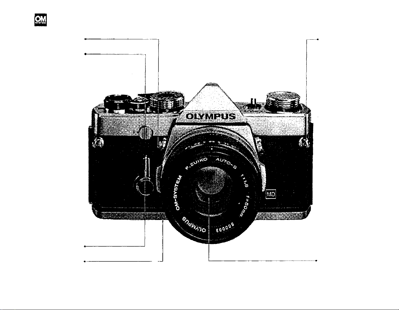
DESCRIPTION OF CONTROLS
Refer to pages in parentheses for detailed
explanations of each part.
Mirror Lock-up Lever
Rewind Release Lever
(P. 29)
(P. 10)
Shoulder
Strap Eyelet
Self-Timer
Preview Button
(P. 29)
(P. 17)
(P. 16)
Standard Lens
1
Page 3
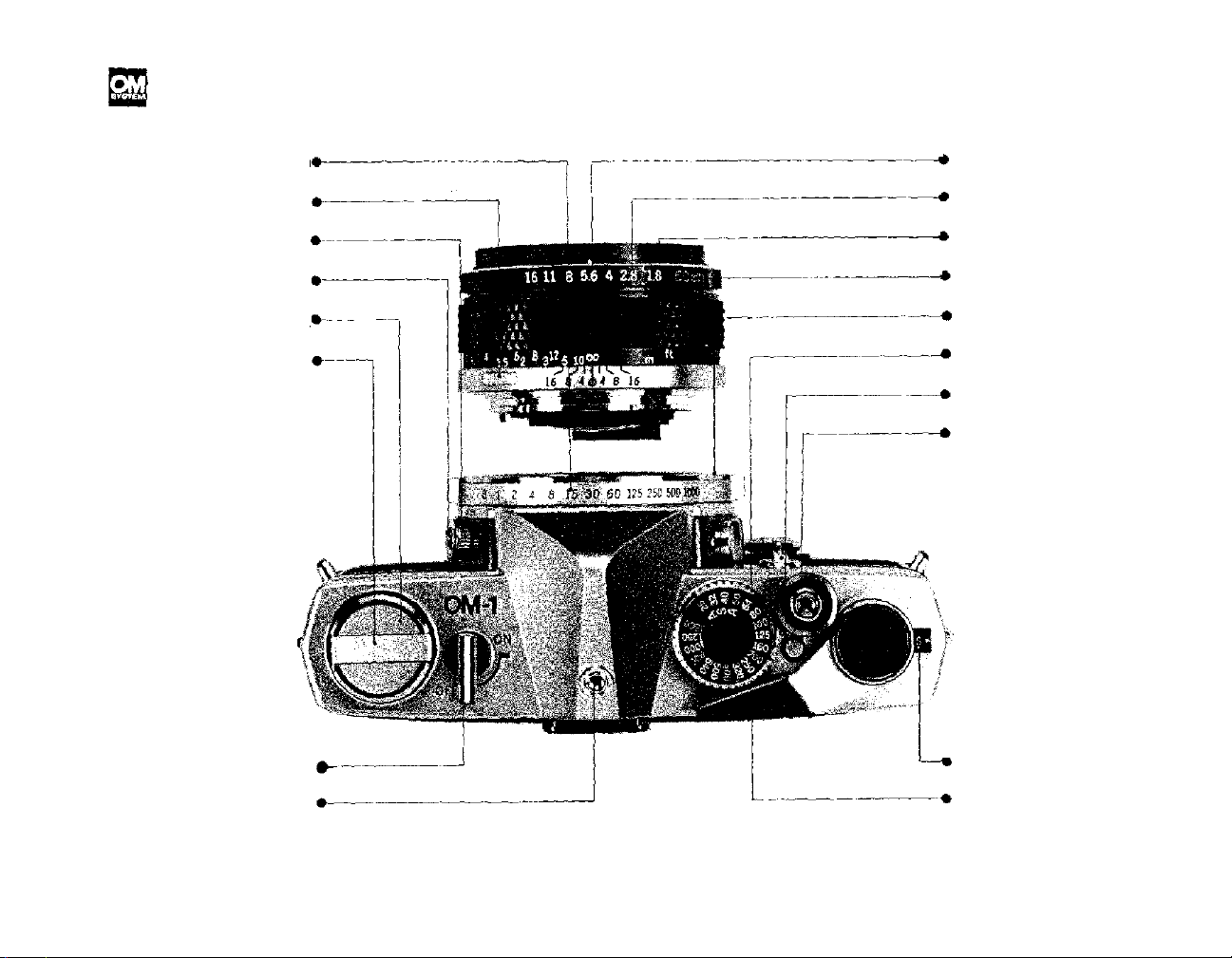
DESCRIPTION OF CONTROLS
The design of the OLYMPUS OM-1 lets you see every camera
control from the top.
Shutter Speed Ring
Lens Release Button
FP and X Flash Selector
Flash Synchronization
Socket
Rewind Knob
/Camera Back Release
Rewind Crank
(P. 11)
(P. 16)
(P. 26)
(P. 26)
(P7•P10)
(P. 10)
(P.17)
Depth of Field Scale
(P.11)
Aperture Ring
(P.15)
Focusing Ring
(P.
16),
Lens Mount Ring
(P.16)
Body Mount Ring
(P.12)
AS A Film Speed Dia l
Film Speed Dial
(P. 12)
Release Button
(P.19)
Shutter Release
Button/Cable
Release Socket
Meter Switc h Lever
Hot Shoe Socket
(P. 13)
(P. 26)
(P.9)
Exposure Counter
(P. 9)
Film Advance Lever
2
Page 4
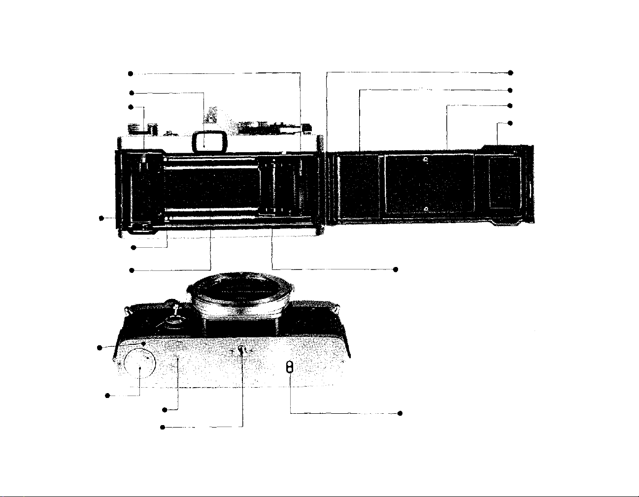
Film Take-Up Spool
Viewfinder Eyepiece
Rewind Shaft
(P.8)
Camera Back
(P.30)
Release Pin
(P.30)
Camera Back
Film Pressure Plate
Film Cartridge
Pressure Spring
Film Chamber
(P. 7)
Film Guide Pins (2)
Shutter Curtain
Guide Pin Hole
(P.23)
Battery Chamber
Motor Drive Socket Cap
Tripod Socket
(P. 7)
(P.8)
(P. 11)
(P.23)
(P.23, 26)
(P. 8)
Dual Sprocket
Motor Coupling Terminal
3
Page 5

TABLE OF CONTENTS
On
OM-1
Description
Specifications
Short Course of Instructions
Inserting
Loading
Front
Operating the Film Advance Lever 9
The
Unloading
Making Double Exposures
Setting the Shutter Speed Ring . .
Setting the Aperture Ring
Setting the ASA Film Speed Di al .
The
Metering
Setting
Focusing
Changing
of
Controls
......
............
the
Battery
the
Film
Lens
Cap
Exposure
the
System
the
Exposure
...............
the
Lens
........
..........
...........
Counter
Film
.......
........
.......
........
........ .
1
5
...
7
7
7
9
....
....
12
13
15
16
12
10
10
11
11
Infrared
Depth
Preview
6
Depth
Holding
Interchangeable Focusing Screens . 20
Motor Drive Photography
Operation
Operation of Basic Motor Drive
Flash
Setting
Locking
Changing the Camera Back
Questions
Care
Photography
of
Field
Button
of
Field
the
Package
Photography
the
up the
and
and
Storage
.......
Scale
........
...........
...........
Camera
of
Winder 1 .......
........
..............
.........
Self-Timer
Answers
Mirror
.......
.......
......
..........
....
....
17
17
17
18
19
22
23
26
29
29
31
32
21
30
On OM System
Zuiko Interchangeable Lens Group 33
Table of Interchangeable Lenses. . 35
Interchangeable Lens Group Units 37
Motor
Drive
Motor
Finder
Flash
Drive
Group
Photo
Group
Units
Group
and
.........
.........
Units
......
.........
38
41
43
45
Flash Photo Group Units ..... 48
Macrophotography Group ..... 51
Macrophotography Units ..... 54
Photomicrography Group ..... 59
Photomicrography Units ..... 62
Chart of Photographic Ranges . .
Phototechnical
Phototechnical
Case
Group
Case
Units
Group
Units
.......
........
.............
..............
64
65
68
69
69
4
Page 6

SPECIFICATIONS
Specifications subject to change witho ut notice.
System:
Camera Type:
Fil m Format:
Standard Lenses:
Lens Mount:
Minimum Focusing Distance:
Lens Accessory Size:
Shutter:
Self-Timer:
Exposure Measurement:
Exposure Range:
Battery:
Film Speed Range:
Viewfinder:
Viewfinder Magnification:
Viewfinder Apparent Field View
Focusing Screens:
Reflex Mirror:
Flash Contacts:
Flash Synchronization:
Hot Shoe Socket:
Film Advance: (Manual)
(Motor Drive)
Exposure Counter:
Film Rewinding:
Camera Back:
Dimensions & Weights:
OLYMPUS OM SYSTEM.
35mm Single Lens Reflex with focal plane shutter.
24mm x 36mm.
50mm F1.8 F Zuiko Auto-S 6 elements in 5 groups.
50mm F1.4 G Zuiko Auto-S 7 elements in 6 groups.
55mm F1.2 G Zuiko Auto-S 7 elements in 6 groups.
OLYMP US OM Mount, bayonet type, rotation angle 70°, flange back 46mm.
45cm (17 3/4") with all standard lenses.
49mm threaded for F1.8 an d F1.4 lenses; 55mm threaded for F1.2 lens.
Focal plane shutter, ring mounted control, with speeds from 1 to 1/1000 second plus B:
4—12 second delay lever type; can be stopped and reset after actuation.
Two highly sensitive CdS cells located on either side of the eyepiece provide through-the-lens
open aperture light measurement. Zero-method wit h needle vi s i b l e in viewfinder. On-Off Switch
located atop camera.
EV 2—17 (ASA 100 with F1.4 standard lens).
1.35 volt mercury battery (Eveready or UCAR EPX625, Mallory PX625, or equivalent)
ASA 25-1600.
Pentaprism type wide-vision finder shows 97% of actual picture field; Interchangeable focusing
screens; Visible exposure meter needle.
0.92X
at
infinity
with
standard
50mm
lens.
23° 30' & 35°.
1-13 Microprism/split image-matte type provided. Interchangeable with any of 12 additional screens.
Oversize, quick return type with mirror lock-up control.
FP·X switch type contact.
With electronic flash (X ) 1 to 1 /60 sec.
With class "M" bulbs ( X) 1 to 1/15 sec.
With class "F" bulbs (X ) 1 t o 1/15 sec.
With focal plane bulbs (FP) 1/60 to 1/1000 sec.
Built-in. Easy to attach Accessory Shoe 1 available.
Ratc het t ype film advance. May be advanced in one stroke or several short strokes for a total of
150° rotation, pre-advance angle 30°. Built-in prevention against double advance with double
exposure override capability.
With Motor Drive 1 unit attached, single-frame and continuous advance at speed of 5 frames
per second (at exposures above 1/500 sec., wit h fresh batteries and at normal temperature and
humidity).
Progressive type from "S" (Start) to 36 and "E" (End). Counter automatically resets to "S''
when camera back is opened.
Rewind crank with automatic-resetting rewind rel eas e lever.
Removable hinge type. Interchangeable with Recorda ta Back 1 and 250 Film Back 1.
With F1.8 lens:
136mm x 83 mm x 81mm (5-3/8" x 3-1/4" x 3-3/16") : 680 gr. (24.0 oz.)
With F1.4 lens: 136mm x 8 3mm x 89mm (5 -3 / 8" x 3-1/4" x 3-1/2") : 740 gr. (26.1 oz .)
With F1.2 lens: 136mm x 83mm x 97mm (5-3/8" x 3-1/4" x 3-13/16") : 820 gr. (28.9 oz.)
Body only:
136mm x 83mm x 50mm (5-3/8" x 3-1/4" x 2") : 510 gr. (18.0 oz.)
5
Page 7
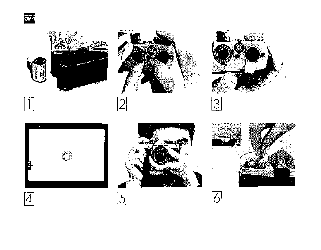
SHORT COURSE OF INSTRUCTIONS
(R efe r to each page for detailed operating instructions.)
Load the camera (see page 7).
Make sure the battery has been
properly inserted and that the
camera back is closed tightly.
Look through the viewfinder.
Compose and focus. Set the prop-
er exposure (see pages 13, 14, 15).
Set ASA Film Speed (see page 12 ).
Take the picture (see page 19).
Hold the camera steady and release the shutter with a slow,
steady pressure.
6
Advance the film until the figure
"1" appears in the exposure coun-
ter window (see page 9).
After the entire film has been
exposed, rewind the film back
into the cartridge (see page 10).
Page 8
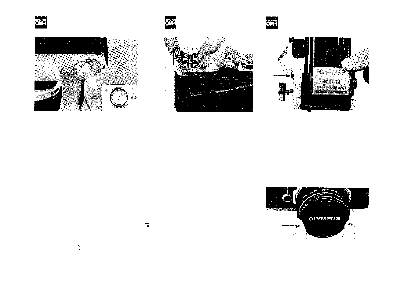
INSERTING THE BATTERY
LOADING THE FILM
FRONT LENS CAP
The OLYMPUS OM-1 is supplied with
a 1.35V mercury battery (JIS H-D type)
to power its through-the-lens exposure
metering system. It will last approximately one year depending upon use
and must be replaced with an Eveready
(UCAR) EPX625, Mallory PX625
or equivalent. Substitutes must not be
used. (NOTE; The exposure meter stops
functioning when the battery runs out.
To prolong battery life, make sure the
Meter Switch Lever is in the "OFF"
position when the camera is not in
use.) To insert the battery:
1) Insert the edge of a coin into the
cap of the battery chamber and turn
counter-clockwise until the cap has
been removed.
1. Open the camera back.
Pull up on the rewind knob. A slight
resistance may be felt before the
camera back snaps partially open.
2) Place the battery in the battery
chamber making sure the positive side
(+) is facing out. The exposure meter
does not function if the battery is
inserted incorrectly.
3) Replace the cap tightly.
7
2. Load the cam era.
Insert a film cartridge in the film
chamber and push the rewind knob
back into its original position. It may
be necessary to turn the rewind knob
slightly before it will lock securely in
place.
Page 9
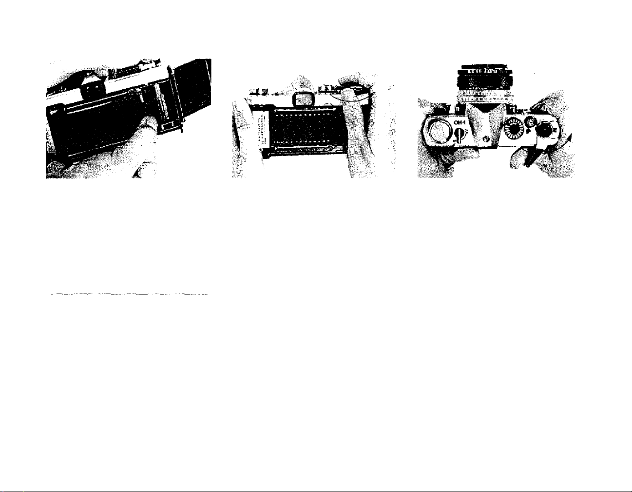
3. Attach the film end to the take-up
spool.
Draw out the film leader and insert it
into one of the slots in the film take-up
spool. Make sure the film is evenly
placed between the film guide pins.
Be careful not to permit the film leader
to protrude out of the opposite slot
when inserted into the spool.
4. Advance the film.
Advance the film using the film advance lever. Make sure that the film
perforations engage on the sprockets
on both sides.
5. Close the camera back.
Close the camera back until it clicks
in t o place.
7. Check the exposure counter window.
Advance the film and depress the
shutter
release button.
Advance
the
film once more until "1" appears in
the exposure counter window. The
rewind knob will rotate in a counterclockwise direction indicating that the
film is advancing properly.
To attach or remove the fro nt lens cap,
press the spring-loaded lens cap retain-
ing clips on either side of the cap. The
cap then fits easily over the accessory
thread of the lens.
6. Tighten the film.
After closing the cover, fold out the
rewind crank and turn it slowly in a
clockwise direction until a slight resist-
ance
is
felt.
This
will
take
up any
slack
in t he film.
8
Page 10
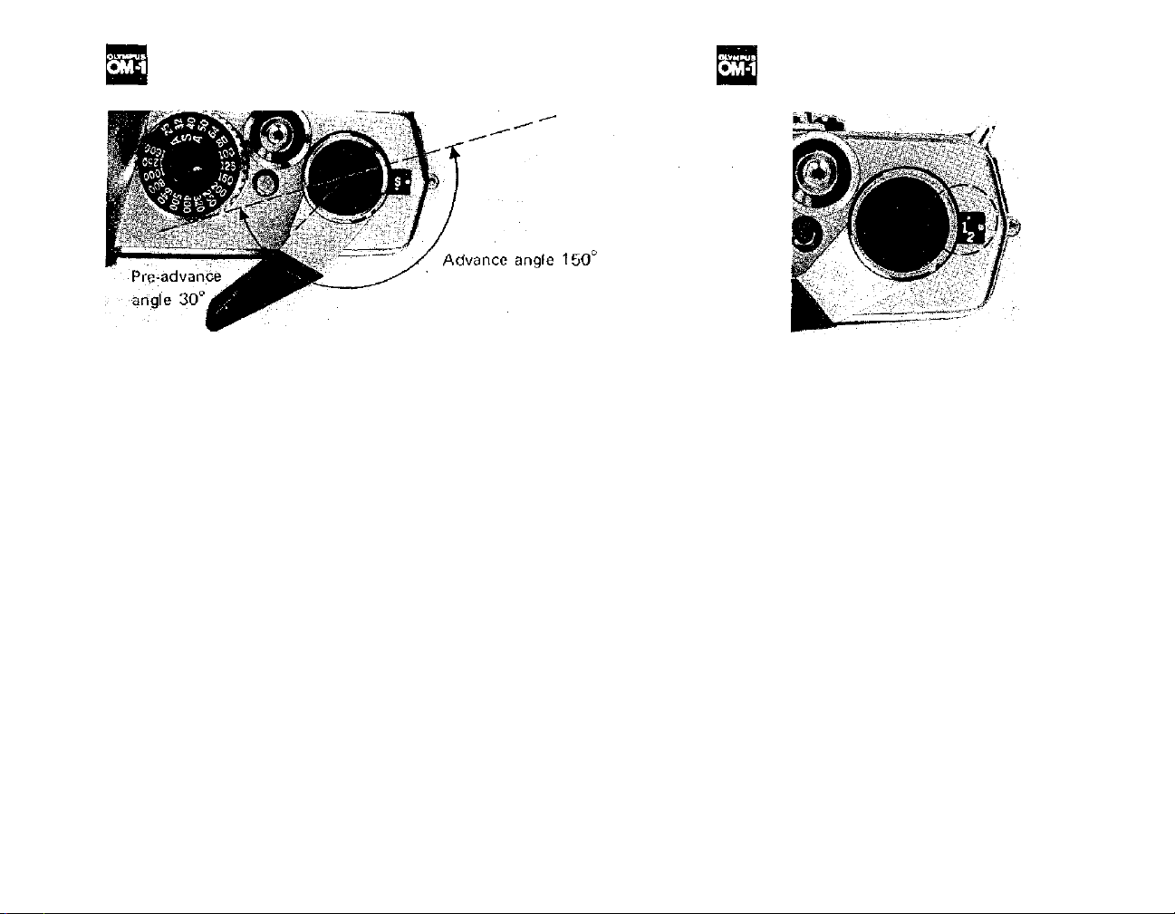
OPERATING THE FILM ADVANCE LEVER
THE EXPOSURE COUNTER
In one stroke the film advance lever:
1) advances the film one full frame,
2) advances the exposure counter, 3)
cocks the shutter, 4) sets the in-
stant return mirror, 5) activates the
automatic diaphragm mechanism and
6) activates double advance and
double exposure prevention mecha-
nism.
Refer to page 21 for Motor Drive
Photography.
To advance the film:
1) Gently pull the film advance lever
away f rom the camera body.
2) Advance the lever to the right as
far as it will go. This can be ac-
complished in a single stroke or in
multiple short strokes.
9
The exposure counter is designed to
indicate the total number of frames
exposed on the film. Each time the
film is advanced by the film advance
lever, the exposure counter automatically adds one frame to the total.
The counter is indexed in even numbers up to 36 plus "S" (start) and "E"
(end). For easy reference, "S", "E",
and numbers 12, 20 and 36 are indicated in gold.
Whenever the camera back is opened,
the exposure counter automatically
returns to "S".
Page 11
UNLOADING THE FILM
When the entire roll of film has been
exposed (indicated by numbers 12, 20
or 36 on the exposure counter depending o n film length), rewind th e film.
1) Turn the rewind release lever coun-
ter-clockwise until the red line is
opposite the "R".
MAKING DOUBLE EXPOSURES
Should you wish to make more than
one exposure on the same frame:
1) After taking the first exposure, turn
the rewind knob slowly in a clockwise
direction until it stops to take o ff any
slack
in the film.
2) Turn the rewind release lever counter-clockwise until the red line is
opposite the " R".
2) Fold out the rewind crank and
wind it in the direction of the arrow.
During the rewind procedure you will
feel tension on the crank. When it
turns fr e e the film has been completely
rewound back into the cartridge.
3) Hold both the rewind knob and
rewind
release
them from turning and advance the
film advance lever. The shutter will
then be cocked for the next exposure
of the frame, without the film being
advanced.
4) Depress the shutter release button
with a slow, steady pressure.
5) After completing the multiple ex-
lever
firmly
10
to
prevent
3) Open the camera ba ck b y pulling up
on the rewind crank and remove the
film cartridge. Keep camera and film
out of direct sunlight.
IMPORTANT: Do not force the film
advance lever if the film has been fully
exposed. If there is some resistance,
rewind the film to prevent tearing.
posure, cover the lens with a lens cap,
advance the film and shoot a blank
frame to avoid overlapping.
You can make as many multiple exposures as you like by repeating the
above procedure. With each exposure
on the same frame (the exposure
counter adds one), the likelihood of
slippage is increased. Practice is re-
quired in order to obtain good results.
Page 12
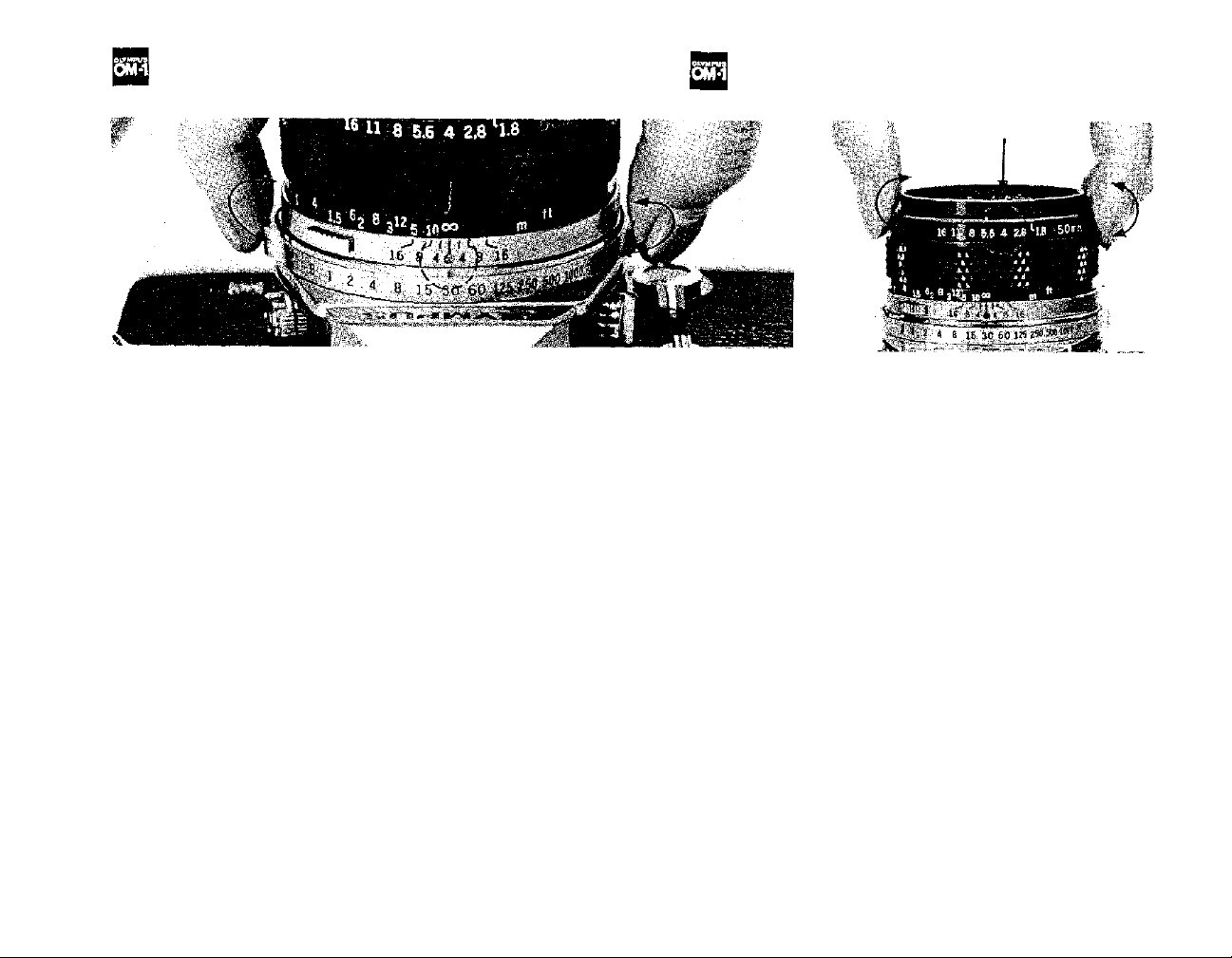
SETTING THE SHUTTER SPEED RING
SETTING THE APERTURE RING
The length of time that light is allowed
to strike the film is controlled by the
focal plane shutter. The shutter consists of two opaque "curtains" which
travel across the opening and allow
light
to
reach
the film.
coordinated movement of these curtains determine in frac tion s of a second
the exposure time for your picture.
For example, 1000 on the shutter
speed ring indicates 1/1000 of a second
and 60 indicates 1/60 of a second. The
figure 1 indicates one full second. The
B (Bulb) setting is used fo r longer time
exposures. A t this setting the shutter
will remain open as long as the shutter
release button is held down. For ex-
posures less than 1/30 of a second, it is
advisable to use a cable release, tripod
or other steadying devices to avoid
The
speed
and
camera movement which can result in
blurred or fuzzy pictures.
To set the shutter speed turn the
shutter speed ring in either direction
until the desired number clicks into
place opposite the reference dot on the
lens barrel. Set the ring only at click-
stop positions as no in-between settings
can be used. Shutter speeds may be set
before
or
after
advancing
NOTE: Speeds from "B" to "60" are
indicated on the ring in blue as an easy
reference to "X" flash synchronization.
11
the
film.
The amount of light allowed to strike
the film is represented by "F" numbers
or "F" stops engraved on the aperture
ring. The higher the F number, the
smaller
opening (more light). When setting the
aperture ring you can use either the
click-stop positions or any in-between
settings to obtain precise exposure.
All lenses in the OLYMPUS OM SYS-
TEM (other than specialized lenses)
control allowing you to focus and
compose
maximum aperture or "wide open."
The diaphragm will au t omatically stop
down to the preselected F stop at the
moment of exposure and immediately
re-open when exposure is completed.
the
lens
opening
lower the number, the larger the lens
provide fully automatic diaphragm
your
picture with
(less light);
the
lens
the
at
Page 13
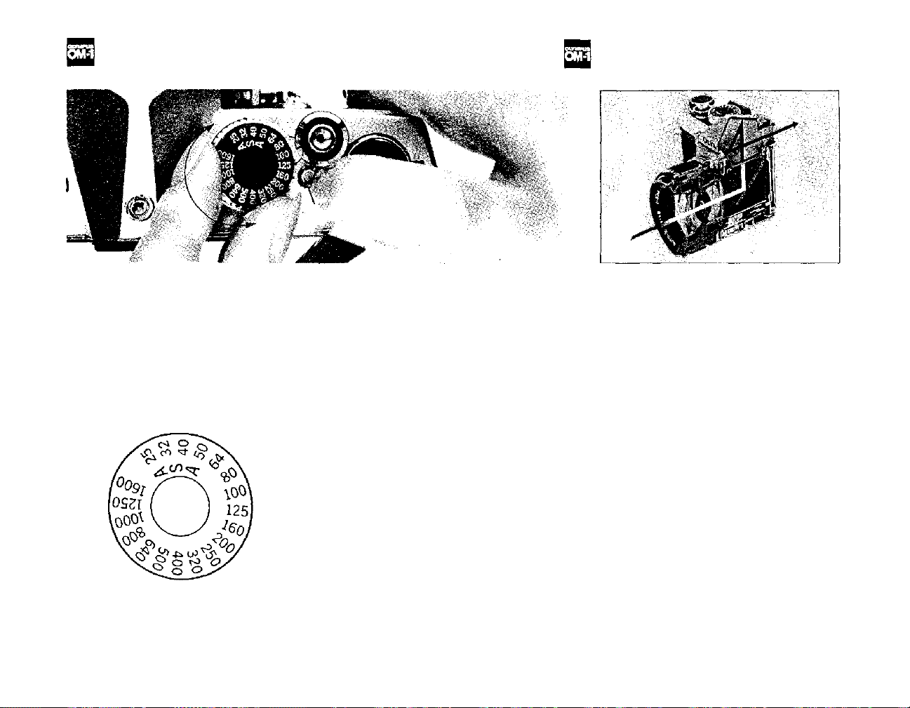
SETTING THE ASA FILM SPEED DIAL
THE METERING SYSTEM
Setting the correct ASA film speed on
the camera is one of the most impor-
tant factors in determining exposure.
In order to obtain properly exposed
pictures, the correct ASA film speed
must be set on the ASA film speed
dial. To set the dial:
1) Pull the film advance lever slightly
away from the camera body.
2)
Press
the
film
speed
button and turn the film speed dial
until the ASA rating for the film being
used is opposite the black line engraved
on the outer ring of the shutter release
button.
3)
Release
that the dial is securely in place and
the
button
dial
making
release
sure
does not move.
12
The OLYMPUS OM-1 incorporates a
built-in, wide-open exposure metering
system which uses two highly sensitive
CdS cells with one postioned on each
side of the eyepiece. These cells measure the actual amount of light enter in g
the lens, placing the greatest emphasis
at the center of the picture area.
Measurements are taken with the lens
diaphragm at maximum aperture (wide
open) allowing you to take full advantage of a brighter viewfinder when
focusing and composing your picture.
The OM-1 metering system operates as
above with all OM System camera
lenses (except a few special lenses)
regardless of the focal length, filters,
etc.
Page 14
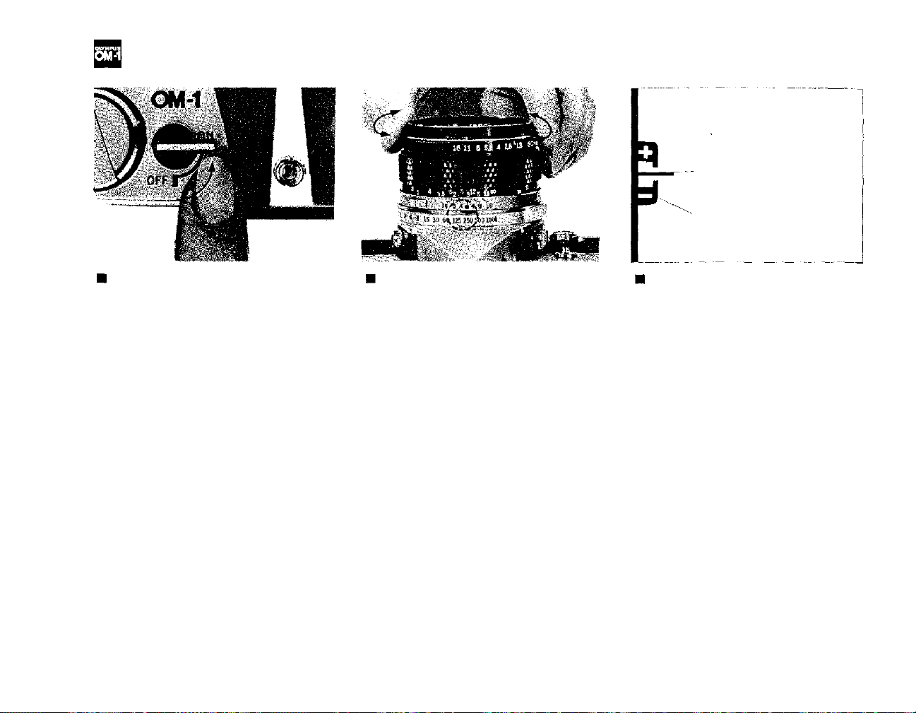
SETTING THE EXPOSURE
Exposure Meter Needle
Exposure Meter Index
Activating the Meter
The OLYMPUS OM-1 metering sys tem
is directly coupled to the shutter speed
ring, aperture ring and ASA film speed
dial.
To activate the meter, move the meter
switch lever at the top of the camera to
the "ON" position. To prolong battery
life, it's a good idea to return the lever
to the "OFF" position when the cam-
era is not in u se.
Preselecting the Shutter Speed
Should you wish to select a shutter
speed to meet a specific photographic
situation (for example, to stop fast
action, eliminate camera shake, etc.):
1) Turn the shutter speed ring until
the desired speed is opposite the red
reference dot on the camera lens.
2) Look through the viewfinder and
turn the aperture ring until the needle
lines up in the center of the index. For
fine exposure adjustment you can use
any intermediate F stop position on
the aperture ring.
3) If the needle will not align proper-
ly, select a new shutter speed. To
correct over-exposure (+), try a faster
speed; to correct under-exposure (–),
try a slower speed.
13
Preselecting the F Stop
Should you wish to preselect the F
stop (for example, to control depth of
field for greater creative impact):
1) Turn the aperture ring until the
desired F stop is opposite the white
index mark at the front of the lens
barrel.
2) Look through the viewfinder and
rotate the shutter speed ring until the
needle lines up as close as possible to
the center of the index. Make sure that
shutter speed meets the other require-
ments of th e situation.
3) Make the final exposure adjustment
by turning the aperture ring slightly
until the needle aligns exactly in the
center of the index.
Page 15
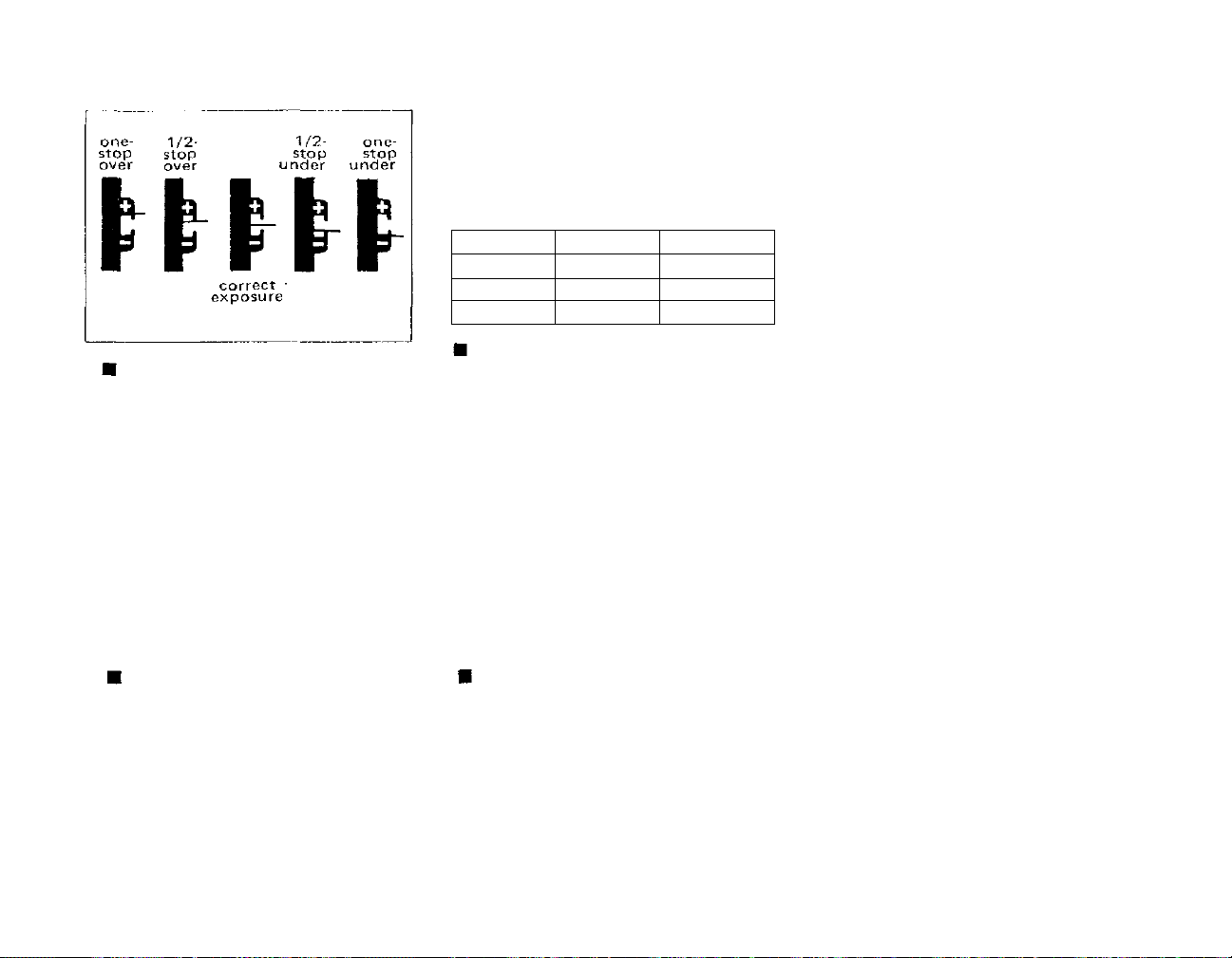
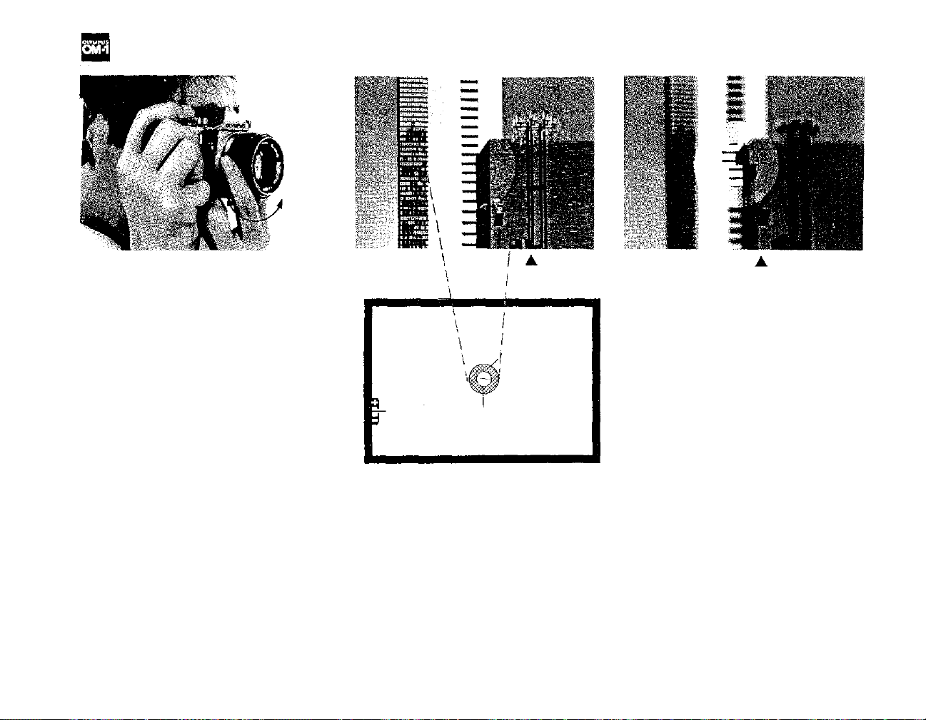
Making Intentional Over- or Under-
exposures
You can make intentional over- or
under-exposures to meet special lighting requirements (such as backlighting,
sidelighting, etc.) by using the central
index in the viewfinder as a guide.
When the needle swings towards the
(+) position, it indicates over-exposure.
When it swings towards (–), it indicates under-exposure. The exact F
stop-n e e dle relationship is shown in the
above diagrams.
Caution in Low-light Exposure
Metering
The meter's e x po s ur e range is EV2—17
(ASA 100 with F1.4.) The combina-
tions listed below indicate the lowest
measurable limit in dealing with dark
subjects.
Below
this
limit
or
with
the
meter
switch at OF F, when the aperture ring
or shutter speed ring is rotated, the
needle might sometimes swing but the
meter will not work.
Lens
50mm F1.8
50mm F1.4
55mm F1.2
F/Stop
Fully open
Fully open
Fully open
Shutter Speed
1/2 sec
1/2 sec
1/2 sec
Stop-down Exposure Readings
When using the OM-1 in conjunction
with the extension tubes, bellows or
the Zuiko Shift Lens it is necessary to
take meter readings with the lens stop-
ped down. After setting the desired
aperture on the aperture ring, stop
the lens diaphragm down and look
through the viewfinder. Rotate the
shutter
speed
ring
until
the
needle
aligns within the center of the index.
(See the instructions on Preselecting
the F Stop, page 13.)
Special Exposure Techniques
1) Backlighting and Sidelighting
When the most important area of the
picture is much darker than the general
picture
area
(strong
light
hitting
the
main subject from behind or from the
side)
the
meter
will
have a tendency
to
read the brightest part of the picture
leaving the main subject under-exposed.
To compensate for this, move in
towards the subject until most of the
subject image appears in the viewfinder
and take your meter reading. After
setting the exposure, return to your
original position to take the picture. If
this procedure cannot be followed, you
can obtain approximately the same
results by simply opening your lens
one full F stop over the indicated
meter reading. (NOTE: With backlighting or sidelighting, it's always a
good idea to use a lens hood to
eliminate unwanted glare.)
2) Strong Frontlighting and Deep
Shadows
When taking a picture of a bright
subject against a dark background
(spotlights, deep shadow areas, etc.)
the meter has a tendency to read the
darkest part of the picture leaving the
main subject over-exposed. To compensate for this use the same procedure
for setting exposure as outlined for
backlighting. You can also approxi-
mate the proper exposure by holding
your position and closing the lens
down one full F stop from the indicated meter reading.
14
Page 16
FOCUSING
The OLYMPUS OM-1 comes equipped
with
the
standard
Focusing
Screen
1-
13 (microprism/split image-matte
type) which is designed to make focus-
ing quick and easy. To focus, look
through the camera viewfinder and turn
the
focusing
until split vertical lines of the subject
image in the rangefinder are aligned or
ring
in
either direction
the "shimmering effect" of the microprisms disappears. If you are focusing
on the matte area, the subject is in
focus when the image is sharp.
* You can determine the distance be-
tween the subject and the film plane
by reading the distance scale on the
focusing ring after you achieve critical
focusing. The actual distance is indi-
cated opposite the red central index
mark on the lens mount ring; the white
scale indicates this distance in meters
In focus
Microprism
Rangefinder Spot
Matte Field
and the orange scale indicates this dis-
tance in feet.
15
Out of focus
The OM-1 viewfinder takes in 97% of
the actual picture area for added convenience when composing your pictures.
Page 17
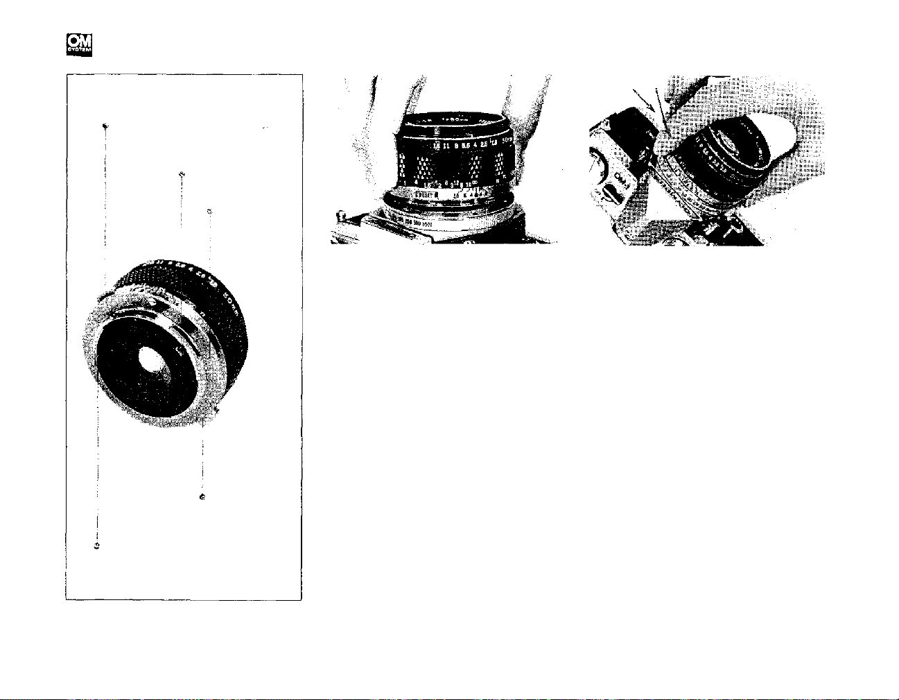
CHANGING THE LENS
Lens Release Button
Meter Coupling
Lens Mount Ring
Depth of Field
Preview Button
Automatic Diaphragm Lever
To mount the lens, grasp the lens
firmly and align the red dots on the
lens flange and the camera mount ring.
Turn the lens clockwise until it locks in
place.
The
lens
release button
will
spring up and you will hear a positive
"click"
when
the
lens
has
been
fully
engaged. Do not apply pressure to the
lens release button during the mounting
procedure.
This will
assure
proper
coupling between the lens and the
meter.
16
The bayonet mount of the OLYMPUS
OM-1 allows you to change lenses
quickly and easily.
To detach the lens, press down on the
lens release button and turn the lens
counter-clockwise. Grasp the lens firmly and remove it from the camera
body.
Protect your lens and camera! Always
attach the front and rear lens caps
when the lens is removed from the
camera to prevent any possibility of
damage. Never leave the camera body
in direct sunlight with the lens removed and, if you plan to store the
camera without the lens, the use of a
bo dy cap is recommended.
Page 18
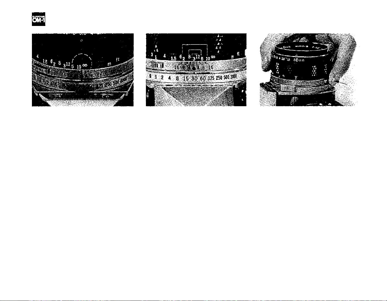
INFRARED PHOTOGRAPHY/DEPTH OF FIELD SCALE/PREVIEW BUTTON
The OM System lenses are provided
with an infrared index mark engraved
in red on the depth of field scale to the
right of the reference dot. When shoot-
ing with infrared film, focus normally
on your subject without the red filter
on and read the subject distance on the
distance scale. Then, turn the focusing
ring to the right until the distance
reading is opposite the infrared index
mark. Your lens will then be in focus for
average infrared photography. Shoot
with the red filter on. In the above
picture the re d index is set at i nfin ity.
The double series of numbers engraved
on the depth of fie ld scale represents F
stops: F4, F8 and F16. Onc e you have
focused on your subject, all objects
within the distance range indicated on
the lens distance scale between the
marks for the F stop you have selecte d
will have acceptable sharpness.
For example, in the above picture the
camera-to-subject distance is 3m (10ft)
and the lens is set at F16. If you read
the distance scale at the points op-
posite the engraved "16" on both sides
of the reference dot, you will find that
the depth of field is from 1. 9m (6ft) to
7m (23ft). The depth of field can be
visually verified by pressing the depth
of field preview button.
17
When you wish to see which objects
fall within the acceptable zone of
sharpness (depth of field), press the
preview button on your lens. The
diaphragm of the lens will stop down
to the preset F stop enabling you to
see the depth of field in the camera
viewfinder.
* If you jerk the preview button while
depressing the shutter button half-
way down, the shutter might get
released. Gently push and release the
preview button to avoid accidentally
releasing the shutter.
Page 19
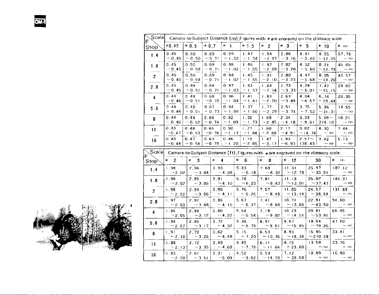
DEPTH OF FIELD
Depth of fie ld is the are a of acceptable
sharpness in front of and behind t he
subject in focus. This depth is deter-
mined by the F stop you have selected
and the distance from the subject in
focus to the film plane. As you get
closer to your subject or as you open
your lens (e.g. from F22 to F2.8) the
depth of field becomes shallower. By
stopping your lens down (e.g. from
F2.8 to F22) or getting farther away
from your subject this depth of field or
zone of acceptable sharpness can be
increased.
Another factor in determining depth of
field is the focal length o f your lens. As
a rule the shorter the focal length, the
greater the zone of acceptable sharpness. The longer the focal length, the
shallower this zone becomes.
The table above shows that when the
camera-to-subject distance is 3m (10ft),
the depth of field at F16 ranges fr om
1.93m ( 6f t) to 6.93m (23ft).
Depth of Field Table (F1.8 & F1.4 Standard Lenses) Circle of least confusion 1/30 mm
F1.8 (1/1000 sec.)
F16
(1/30
sec.)
18
Page 20
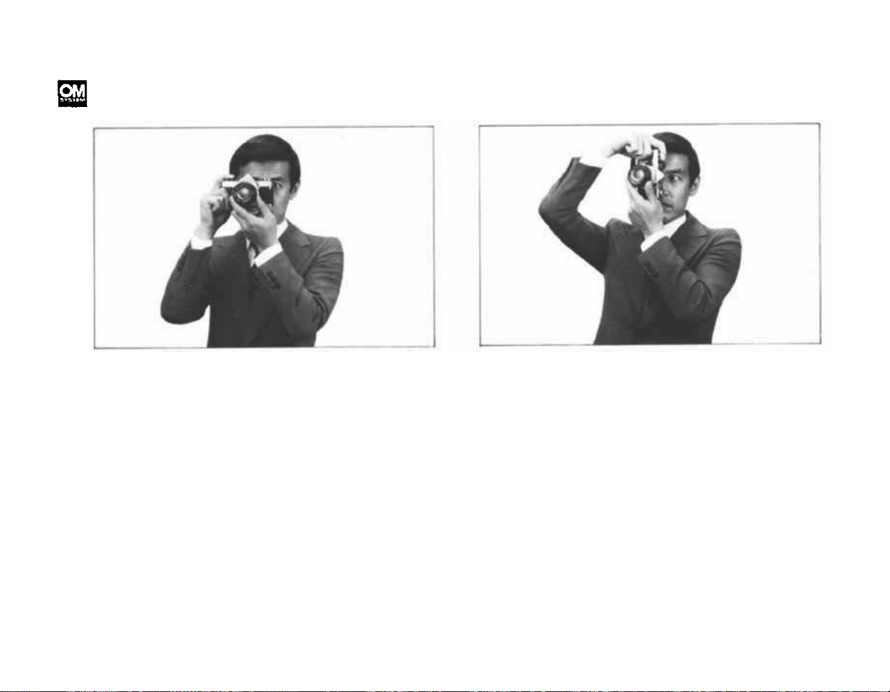
HOLDING THE CAMERA
Proper camera handling is important in assuring
the sharpest possible pictures.
Holding th e Camera Horizontally
Keep both elbows close to the body, to steady
the camera.
Putting the Camera into Operation
The aperture ring, focusing ring and shutter speed
ring are so arranged as to enable one hand opera-
tion right up to the moment the shutter is released.
Hold your breath at the moment of shutter release.
Transport the film advance lever with your right
thumb and squeeze the release button smoothly
using the cushion, not the tip, of your index
finger.
Holding the Camera Vertically
For vertical shooting, keep one elbow close to
your body and press the camera tightly against
your forehead.
NOTE: Steady yourself against any nearby sup-
port (such as a tre e, fence, or wall) whenever pos -
sible.
NOTE: For telephotography, or slow shutter
speed photography, it is recommended that you
use a tripod and hold the camera steady with
you r hands.
19
Page 21
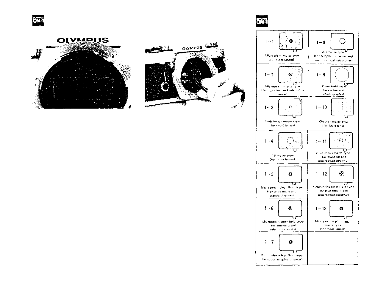
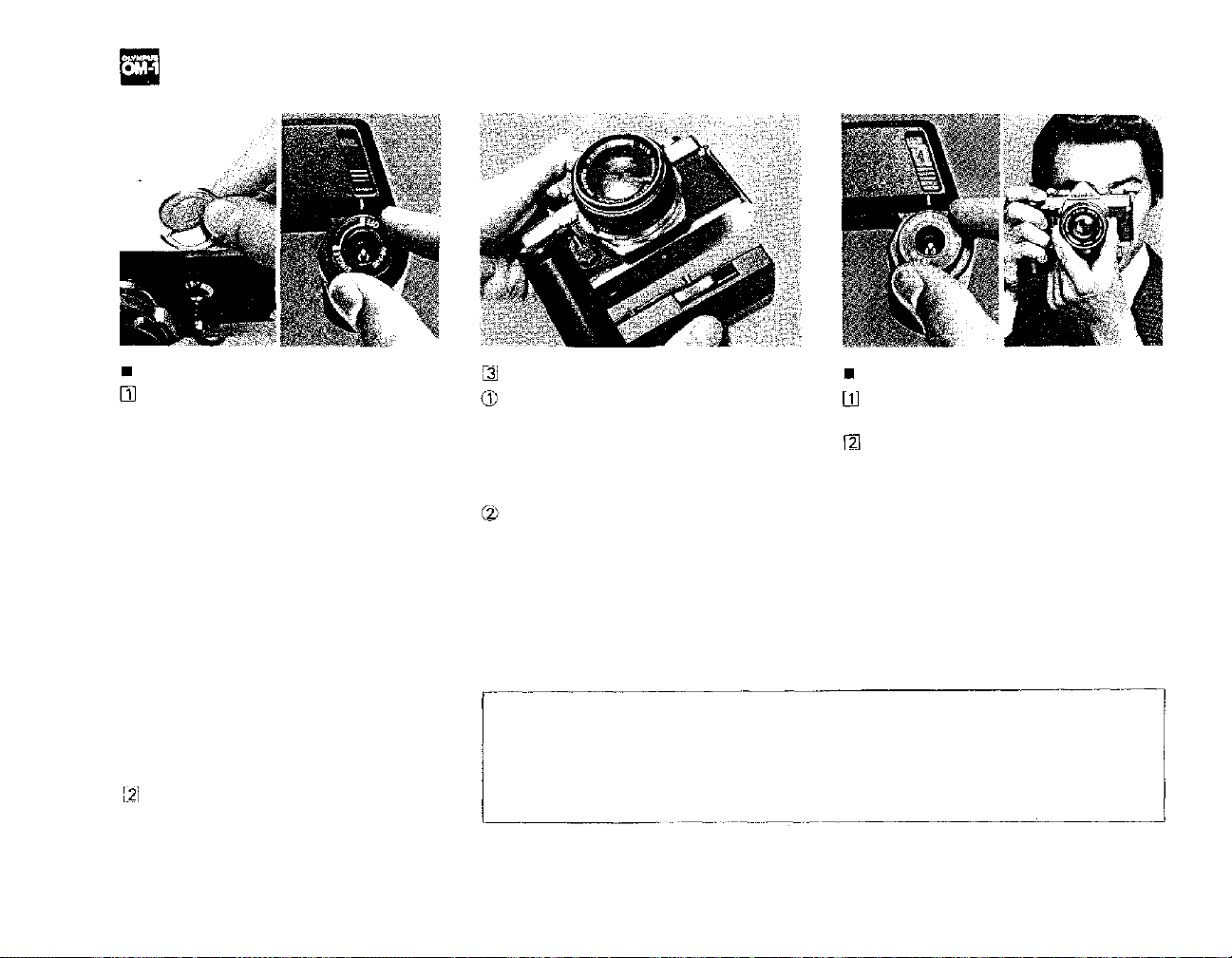
INTERCHANGEABLE
FOCUSING SCREENS
(Handle with extreme care.)
List of Optional Focusing
Screens
The OM System interchangeable fo-
cusing screens provide you with the
ultimate in focusing versatility. Optional screens are available to suit
virtually every picture-taking situation.
The
focusing
special tool. To remove the focusing
screen:
a) Detach the camera lens from the
camera body (see p. 16).
b) Use the special tool provided to
push up on the release catch underneath the top ledge of the mirror
box (see the photo above). This
allows the screen and screen frame
to drop down.
c) Remove the screen from inside the
camera by gripping the tip of the
screen with the tool as shown.
d) To install the screen, fit it in the
screens
come
with
a
frame and push the frame upward
gently until it clicks into place.
Gently shake the camera body to
make sure the screen is held securely in place.
IMPORTANT: Although the above
procedure could be done with fingers,
it is recommended that you use the
special tool supplied. Changing focus-
ing screens is a procedure to be han-
dled with great care. Trying to change
screen with your fingers can result in
fingerprints and costly damage to the
surface of the screen, the prism, or the
mirror. Should this occur, cleaning or
repair MUST be handled by an authorized service center. Such damage is not
covered by the product warranty.
20
* See page 44 for
details.
(Specifications
subject to change
without notice.)
Page 22

MOTOR DRIVE PHOTOGRAPHY
Motor Drive has many exciting recreational, professional and scientific
applications including sports photo-
graphy, action portraits, copying litera-
ture, wildlife photography and time-
lapse photography.
By automatically advancing the film
and cocking the shutter, the motor
drive not only frees the photographer
from the burden of manually advancing the film, but also allows him to
shoot a series
of
pictures
that
might
otherwise be lost through the timeconsuming manual method.
The Motor Drive package is sp ecifically
tailored to the compact size of the
Olympus OM-1. Extremely small and
lightweight, the Motor Drive 1 mounts
directly to the camera base creating
one of the most compact and ma-
neuverable
able. Although reduced in size and
weight, the OM System Motor Drive
motor
drive
systems avail-
Group excels in performance. The basic Motor Drive package can provide
operation up to 5 frames per second in
optimum conditions*, has single release capability and offers motor drive
sequence applications over a wide
range of shutter speeds.
21
The following instructions (pp. 23-25)
are for the basic motor drive system
consisting of the Olympus OM-1, Motor
Drive 1, and M.18V Control Grip 1 or
M.15V Ni-Cd Control Pack 1.
*Optimum conditions: Maximum
framing
types of films and batteries, etc. The
word optimum implies such conditions
in which sequence filming is made at
normal temperatures at shutter speeds
of 1/500 of a second and faster, using
the M. 18V Control Grip 1 containing
fresh superpower manganese batteries.
Cartridges with smooth film moving
must al so be used.
rate
varies
with
temperatures,
Page 23
OPERATION OF WINDER 1
Attaching the Winder 1
Remove the motor drive socket cap.
Remove the motor drive socket cap
from the camera base plate by rotating it counter-clockwise with a coin
until the index dot on the cap is
aligned with the index dot on the
camera.
To replace the cap, align the index
dot on the cap with the index dot on
the camera, and turn the cap clockwise with a coin until the index dot
on the camera is aligned with the
groove on the cap.
(The removed motor drive cap can be
stored in the socket cap storage positioned on the underside of the battery
holder compartment.)
Pull up and rotate the switch dial to
the "OFF" position.
Attach the Winder 1
Remove the M.6V Battery Holder 1
from inside t he winder, insert four 1.5
V
penlight
battery holder, and put it back into the
compartment.
the guide pin hole on the camera base
plate. To assure proper con n ection, ad-
just the position of the Winder 1 until
it is flush with the camera. Turn the
clamping screw clockwise until the
Winder 1 is securely attached to the
camera base plate.
The Winder 1, designed primarily for
single-frame shooting, operates on
four self-contained AA batteries and
is extremely compact and light. The
unit advances the f ilm and cocks the
(AA)
size
batteries
Insert the motor drive guide pin into
22
into
the
Taking the pictures
Pull up and rotate the switch dial
to the "SINGLE" position.
Press the shutter release.
shutter as soon as exposure is made
(wind-on time—0.3 sec.), so that
the photographer can always be ready
to freeze the subject at the right
moments.
Page 24

OPERATION OF BASIC MOTOR DRIVE PACKAGE
Attaching the Motor Drive 1
Remove the motor drive socket cap.
(See page 22, left column.)
IMPORTANT:
* Always store the socket cap in the
same place to avoid loss.
* After removing the motor drive from
the camera, be sure to replace the socket
cap to keep the camera fr ee of dust and
Attach the Motor Drive 1 in the same
manner as with the Winder 1. (See page
22, middle column.)
dirt, and to prevent the possibility of
stray light e nte rin g the socket and fog-
ging the film.
* Do not remove the socket cap when
you do not use the motor drive.
23
Attaching the M. 18V Control Grip
Remove the M. 18V Battery Holder
1, insert twelve 1.5V penlight (AA) size
batteries into th e battery holder, and
re-insert the battery holder into the
Cont rol Grip.
Align the red index line on the rear
of the control grip with the red index
line on the rear frame of the motor drive
unit until the mounting catch is engaged.
Carefully push the control grip for-
ward
until
it
snaps
into
the
front
of the
motor drive.
*Voltage Requirement: DC 18V with
"AA" (penlight) size batteries, or DC
12V—16V with external power sources
of large potentiality in conjunction
with relay cords.
Page 25

Attaching the M. 15V Ni-Cd Control
Pack 1
Prior to use, the Control Pack should be
checked to insure that it has been adequately charged. If its charge is inade-
quate, us e the M. 15V Ni-Cd Charger.
Aligning the red index lines of the Motor
Drive 1 and the Contr ol Pack, engage the
mount catch. Then push the Control
Pack forward and upward until it snaps
on the motor drive, then clamp securely.
Photography with the Motor Drive
Units
Using the M. 18V Control Grip 1
Unlock the shutter release lock lever
on the Control Grip by moving it for-
ward and upward.
* The lever is provided to lock
the shutter release on the Control Grip
for safety sake in general or when a
relay cord is used.
Turn th e mode selec tor on the Con-
trol Grip to either "SINGLE" or "SE-
QUENCE". Set the mode selector to
the "OFF" position when the Motor
Drive 1 is not in use.
* At "SINGLE", exposure is possible
at all shutter speeds from 1 sec. to
1/1000 sec.
At "SEQUENCE", exposure is possible
at al l sh utter speeds except B. and 1 sec.
24
You may use either the shutter re-
lease
on the
Control
ter release on the Motor Drive 1 to trig-
ger the shutter. It is generally more convenient to use the shutter release on the
Control Grip when the camera is held in
Grip
1 or the
shut-
the horizontal position and the shutter
release on the Motor Drive 1 when the
camera is held in the vertical position.
Page 26

Using the M. 15V Ni-Cd Control Pack 1
Slide the shutter release lock button on the Control Pack to the unlock
position.
* The button is provided to lock the
shutter release on the Control Pack for
safety sake in general or when a relay
cord is used, etc.
Pu ll an d turn th e mo de selector until
it clicks to either "SINGLE" or "SE-
QUENCE".
In either mode, available shutter speeds
are the same as those with the Control
Grip. (See page 24, middle column.)
You may use either the shutter re-
lease on the Control Pack 1 or the shutter release on the Motor Drive 1 to trigger the shutter. It is generally conven-
ient to use the shutter release on the
Motor Drive 1 and the shutter release on
the Contr ol Pack 1 fo r use with the 250
Film Back 1.
25
Loading the Film
Always try to load your camera after
the motor drive has been attached.
This eliminates even the remotest possibility of light leak through the motor
drive socket. If this is not possible,
attach the Motor Drive unit in a dimlylit area.
Page 27

FLASH PHOTOGRAPHY
Electronic flash or bulbs may be used to
soften shadows in daylight conditions a s
well as to provide artificial illumination
when available light is inadequate for
proper exposure.
Your choice of a flash unit will depend
upon your individual photographic
needs, and may include the Olympus
Quick Auto 310, PS 200 Quick or
PS
200.
The Accessory Shoe 1 is screwed into
the hot shoe socket on the OM-1
pentaprism housing to provide direct
contact with the clip-on type electronic
flash.
(For the selection of units, see page
45.)
Use of Electronic Flash Units
Attach the Accessory Shoe 1 to the
OM-1.
* Detach the acessory shoe when a fla sh
is not mounted on the camera (because
the shoe may come in the way during
photography), or whe n a side-mounting
bracket is used to support the flash unit
(because you may feel a small electrical shock when touching the terminal
contact of the accessory shoe).
Mount the flash unit on the camera.
Slide the flash unit into the camera's
accessory
* If your electronic flash unit does not
have a direct contact "hot shoe", connect its synchro cord to the flash
shoe
as far as it
will
go.
synchro socket on the camera.
Set the camera's synchro terminal
switch (FP and X flash selector) to
"X".
26
Page 28

Set the shutter speed ring to a shut-
ter speed of 1/60 second or slower (all
shutter speeds indicated in blue on the
shutter speed rin g) .
Set the F stop on the aperture ring.
Auto Flash Exposure Control
Follow your flash equipment instructions for the selection of F stop for
automatic flash exposure control (in
case of the Quick Auto 310, one of
F4,
F5.6, F8; ASA 100).
* The TTL AUTO setting on the Quick
Auto 310 is exclusively for use with
the OM-2 and cannot be used with the
OM-1.
Manual Flash Exposure Control
Determine the correct F stop for proper
flash exposure by using the calculator
dial or exposure table provided with
your flash equipment. You may also
determine the correct F stop by using
the following formula:
DAYLIGHT FILL-IN FLASH
Manual Flash Exposure Control
If your electronic flash unit has
manual/auto flash exposure control, set
it for manual operation.
Focus on your subject to determine
the camera-to-subject distance.
Using the calculator dial, exposure
table, or guide number formula, deter-
mine the correct F stop for proper flash
exposure at the distance you found in
Step 2. Set this F stop wit h the camer a
aperture ring. In case of the Quick Auto
310, after setting the auto/manual
switch dial to the "HI" position, read
the F number corresponding with the
planned flash-to-subject distance, using
the distance scale provided.
Turn the shutter speed ring until the
meter needle centers between the overand under-exposure index marks in the
camera viewfinder.
If the shutter speed is 1/60 second or
slower, you are ready to take the picture.
If the shutter speed is faster than 1/60
second, the flash will not fire if you
attempt to t ake the picture. Th erefore,
you must readjust the exposure settings
27
Page 29

as follows:
a. Reset the shutter speed to 1/60 second.
b. Turn the aperture ring until the me-
ter needle centers between the over- and
under-exposure index marks in the cam-
era viewfinder.
c. Using the flash calculator dial, exposure tables, or guide number formula,
determine the correct flash-to-subject
distance for the F stop now set on the
camera's aperture ring,
d. Move to this distance from the sub-
ject and re-focus or remove the flash
unit from the camera and move it only
to this distance from the subject using a
synchro cord extension to maintain
flash synchronization with the camera.
Automatic Flash Exposure Control
If your electronic flash unit has
manual/auto flash exposure control, set
it for auto operation.
Set the camera's shutter speed ring
to 1/60 second.
Turn the aperture ring until the me-
ter needle centers between the o ve r - and
under-exposure index marks in the cam-
era's viewfinder.
Focus on your subject to determine
the camera-to-subject distance.
If your electronic flash unit has an
"AUTO F STOP" that corresponds with
the F stop set on your camera and if
that "AUTO F STOP" will provide automatic flash control within the distance range you found in Step 5, you
may take the picture using this "AUTO
F STOP" setting on your electronic
flash unit. If these conditions are not
met, use the procedures for Manual
Flash Exposure Control. (In case of the
Quick Auto 310, determine the F
number and set the auto/manual
switch dial to one of F4, F5.6 or F8;
ASA
100).
FLASHBULB PHOTOGRAPHY
Mount the Accessory Shoe 1 to th e
camera and insert the shoe mount o f t h e
flash unit into the accessory shoe.
* If your flash unit does not have a "hot
shoe" contact, plug the flash unit's
synchro cord into the synchronizing
socket.
Select the proper shutter speed and
synchro setting from the table below
according to the type of bulb being used
and make these settings on the camera.
Determine the correct F stop for
flash exposure by using the guide num-
ber formula. (See page 27.)
* The guide number for any flash-
bulb/film combination m a y be found o n
the flashbulb packaging.
Set the correct F stop with the cam-
era's aperture ring.
The table indicates proper synchronization speeds for most flash equipment.
Recommended;
Not recommended due to bulb quality.
28
Page 30

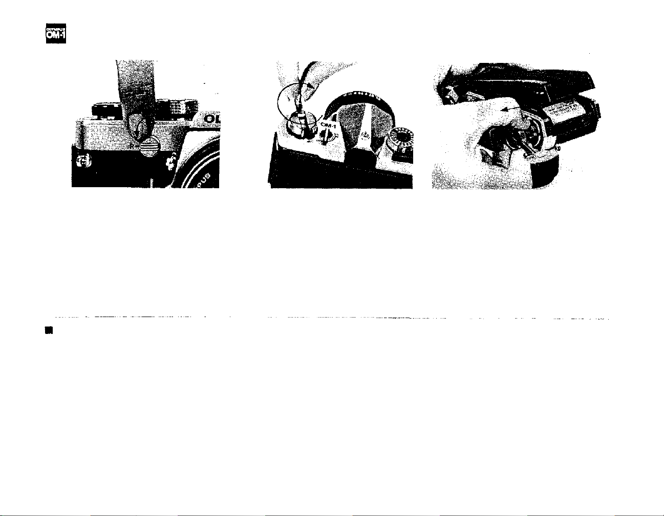
SETTING THE SELF-TIMER
LOCKING UP THE MIRROR
The self-timer provides a method of
taking delayed action pictures allowing
you to get into your own photographs.
It is also ideal for macrophotography
when a cable release is not available.
To set the self-timer:
1) Rotate the self-timer lever counterclockwise until it stops (approximately
180°).
Make
advanced properly.
2) Turn the start lever clockwise to
the vertical position to activate the
sure
the
film
has
been
self-timer lever. The shutter will then
be released in approximately 12 sec-
onds. You can adjust the delay time
between four and twelve seconds by
adjusting the lever as shown above.
If the film has not been advanced
properly, the timer lever will stop
halfway and the shutter will not fire.
To re-activate the timer, move the start
lever counter-clockwise to stop the
timer lever, return the timer lever to
the starting position, and advance the
film. Then, turn the start lever again.
NOTE: If you do not reset the selftimer,
the
timer
lever
will
begin
moving
immediately after advancing the film
and the shutter will be released earlier
th a n expected.
You may set the self-timer lever either
before or after advancing the film.
Even after setting the lever, you can
release the shutter by pressing the
shutter
release button. To stop
self-timer during its operation, turn the
the
start lever counter-clockwise.
29
To minimize camera vibration in close-
ups, reproduction work, macro-
photography and photomicrography,
you can lock the instant return mirror
in the up position to eliminate mirror
shock. This is also handy in rapid
sequence shooting. To lock up the
mirror, compose and focus on your
subject and the n turn the mirror lock-
up lever counter-clockwise until it
stops (approximately 90°). After
shooting, always return the lock-up
lever to its original position.
NOTE: Yo u can lock up the mirror at
any photographing stage — before or
after advancing the film. However, do
not carry the camera in direct sunlight
with the mirror locked up. This can
result in damage to the shutter curtains.
Page 31

CHANGING THE CAMERA BACK
The camera back of the OM-1 is fully
interchangeable with the Recordata
Back 1 and 250 F ilm B ac k 1. To remove
the camera back, push down on the re-
lease pin as shown. Do not remove the
back unless necessary.
Recordata Back 1
The Recordata Back 1 registers data
such as date, number, alphabetical code,
etc. directly on the picture.
250 Film Back 1
The 250 Film Back 1 is designed for
winder or motor drive shooting; it accepts a bulk loaded magazine of 250
frames. (See page 42.)
30
Page 32

SOME QUESTIONS & ANSWERS
Q: My camera is loaded with film but
the rewind knob doesn't rotate when I
advance the film advance lever. Why?
A: The film leader may not be inserted
in the film take-up spool and the film
is not advancing properly. See pages 7
& 8.
Q: The film is not advancing. Why?
A: The shutter may be cocked and
ready to fire. Try pressing the shutter
r
elease button.
If
this
is not the
case,
your film may be fully exposed. Check
the exposure counter. If you feel ten-
sion on the film advance lever, DO
NOT FORCE IT. Rewind the film. See
pages 9 & 10.
Q: The shutter release button will not
move and I can't take the picture.
Why?
A: The film advance lever may not
have been fully advanced. See page 9.
Q: The rewind crank will not turn
when I try to rewind the film. Why?
A: The rewind release lever may not be
set properly. Make sure the lever is
rotated until the red line is opposite
the "R." See page 10.
Q: Why can't I turn the ASA film
speed dial?
A: The film speed dial release button
must be pressed before the dial can be
turned. Once the dial had been set,
release
the
button
and
make
sure
the
dial has locked into plac e. S e e page 12.
Q: Why isn't the needle in the viewfinder moving?
A: First, make sure the meter switch
lever is set to the "ON" position. If the
meter is on, turn the camera towards a
bright light source. If the needle still
will not move, the battery may not be
inserted, may be inserted improperly
or may be drained. Replace the battery
or insert it properly. See page 7.
Q: I cannot center the exposure needle
on the index. Wh y?
A: If the exposure needle will not center on the index, adjust the shutter
speed or F stop until the needle is
centered.
To obtain proper exposure, you may
use an ND (neutral density) filter w h e n
the subject is too bright, or an electronic flash or flash bulb when the
subject is too dark.
Q: How do I take meter readings when
a bellows or extension tubes are
mounted to my camera?
A: Since lens extension devices disconnect the automatic diaphragm
mechanism between camera and lens,
readings must be taken with the lens
stopped-down. Take an exposure read-
ing using the procedure outlined on
page 14.
Q: How can I remove dust from inside
the viewfinder?
A: After detaching the focusing screen,
blow away any dust with an air blower.
(See page 20.) Never wipe the surfaces
of the screens, prisms, or mirror with
cloth or paper.
Q: The microprism in the center of the
viewfinder "shimmers" and darkens.
Is that normal?
A: Yes, this is a natural phenomenon
that occurs when a lens with a maxi-
mum aperture smaller than F5 is
mounted on the camera. It also
happens with a standard lens when the
depth of field preview button is
pressed. The microprism is not faulty.
Q: The viewfinder is totally dark and I
can't see anything. Why?
A: Make sure you have removed the
lens cap. If the cap has been removed,
the mirror lock-up lever may be in the
up position. Return the mirror to its
operational position. See page 29.
31
Page 33

CARE AND STORAGE
Q: When I touch the terminal contact
of the Accessory Shoe 1 I fe el current.
Why?
A: This is normal when a side-
mounting type flash unit connected to
the camera is being turned on. At this
point you are not using the accessory
shoe so it should be detached. See
page 26.
Q: The self-timer lever stopped halfway and plays idly. Why?
A: The self-timer lever stopped half
way because the film advance lever has
not been transported fully and hence
the shutter cannot be released. Turn the
start lever counter-clockwise, reset the
self-timer lever to the desired time,
advance the film fully and turn the
start lever clockwise to activate. The
self-timer lever plays because you for-
got to
turn
the
start
lever
to
release
the
shutter after you have set the self-timer
lever. See page 29.
Q: Can I take the pictures without the
motor drive socket cap in place?
A: No, you must replace the cap whenever the motor drive or winder is not
attached to the camera's baseplate because dust and dirt may get into the
socket causing malfunction and light
may enter and fog the film. See page
23.
1. When you do not use the camera for
a long period of time, store it with the
shutter uncocked and turn off the selftimer and exposure meter. Keep it free
from dust and moisture, and remove it
from th e case.
2. When storing the camera for a long
period of time, remove the battery.
Wipe battery surfaces with a dry cotton cloth before re-inserting into
the camera.
3. Avoid dropping or hitting the camera.
4. Never store the camera where temperatures exceed 50°C (122°F). When
you use the camera in temperatures un-
der -20°C (- 4°F), it may sometimes
fail to operate properly. To avoid this,
warm the camera before use. Protect
against excess moisture by using silica
gel or other desiccant.
5. After use near the ocean, wipe th e
camera
surfaces
clean
with a soft
cloth;
never leave salt on the camera. (Salt may
be airborne near the ocean and collect
on the camera even though it has not
been in direct contact with water.)
6. Avoid excessive force when mounting on a tripod.
7. Never expose the camera to direct
sunlight. Avoid areas exposed to salt
32
water, radios, TV sets, or magnets.
8. Have all repairs performed by an authorized OLYMPUS Service Center.
You may send it directly or through the
store where you bought your camera.
9. Avoid touching the surfaces of the
lens. Clean only with an air brush, anti-
static brush, or wipe it lightly with a
camel hair brush or lens tissue. In EXTREME cases, use a clean, soft cotton
cloth moistened with denatured alco-
hol. NEVER rub the lens surfaces with
your finger, clothing, or other abrasive
material.
10. If dust or fingerprints collect on the
mirror, focusing screen, or prism, take,
the camera to an authorized OLYMPUS
Service Center. It needs pr ofessional attention.
11. Do not press the release lever at ran-
dom.
12. Do not touch any part that moves at
high speed such as the shutter, instant
return mirror, diaphragm, etc.
Page 34

ZUIKO INTERCHANGEABLE LENS GROUP
One of many advantages of the single
lens reflex type of camera is the large
variety of interchangeable lenses available. The Zuiko Interchangeable Lens
Group (designed and manufactured by
Olympus) comprises 32 lenses including those now in the course of development. Zuiko lenses have always
enjoyed a high reputation in photo-
graphic circles — new design tech-
nology has made possible a new series
of innovative, high performance lenses.
These lenses have a host of special
features including a new construction
that compensates for close focus aberrations, increased aperture ratio in the
wide angle lenses, and reduction in tele-
photo lens size and weight. The OM
System adopts 49mm filters for most
lenses from 21mm to 200mm. As p art
of the OM System design all the lenses
now offer higher performance in small
configurations. Olympus has produced
lenses for microscopes for many years
and the new Zuiko lenses benefit from
this scientific experience. See the
"OM System Zuiko Interchangeable
Lenses" instructions for further infor-
mation.
33
Page 35

Page 36

TABLE OF INTERCHANGEABLE LENSES
TYPE
FISHEYE
SUPER WIDE
WIDE
STANDARD
ZOOM
TELEPHOTO
SUPER
TELEPHOTO
SPECIAL USE
INTERCHANGEABLE LENSES
ZUIKO FISHEYE
ZUIKO FISHEYE
ZUIKO MC
ZUIKO
ZUIKO MC
ZUIKO
ZUIKO MC
ZUIKO
ZUIKO MC
ZUIKO
ZUIKO SHIFT
ZUIKO
ZUIKO
ZUIKO
ZUIKO MC MACRO
ZUIKO MC ZOOM
ZUIKO ZOOM
ZUIKO MC
ZUIKO
ZUIKO MC
ZUIKO
ZUIKO MC
ZUIKO MC
ZUIKO
ZUIKO
ZUIKO MC
ZUIKO MC
ZUIKO MC
ZUIKO MC MACRO
ZUIKO MC MACRO
ZUIKO MC 1:1 MACRO 80mm F4
8mm
16mm
18mm F 3 . 5
21mm F3.5
24mm F2
24mm F2.8
28mm F2
28mm F3.5
35mm F2
35mm F2.8
35mm F2.8
55mm F1.2
50mm F1.4
50mm F1.8
50mm F3.5
35-70mm F3.6
75-150mm F4
85mm F2
100mm F2 . 8
135mm F2.8
135mm F3.5
180mm F2 .8
200mm F4
200mm F5
300mm F4 .5
400mm F6.3
600mm F6.5
1000mm F11
20mm F3.5
38mm F3.5
ANGLE OF VIEW
F2.8
F3.5
(83 ° at max. shif t)
at highest mag.
at highest mag.
at highest mag.
180° (circle)
180°
100°
92°
84°
84°
75°
75°
63°
63°
63°
43°
47°
47°
47°
64°-
34°
3 2°-16°
29°
24°
18°
18°
14°
12°
12°
8°
6°
4°
2.5°
9°
9°
9°
OPTICAL
CONSTRUCTION
ELEMENT GROUP
11–7
11–8
11–9
7–7
10–8
8–7
9–8
7–7
8–7
7–6
8–7
7–6
7–6
6–5
5–4
10–8
15–11
6–4
5–5
5–5
5–4
5–5
5–4
6–5
6–4
5–5
6–4
5–5
4–3
5–4
6–4
35
DIAPHRAGM
AUTO.
AUTO.
AUTO.
AUTO.
AUTO.
AUTO.
AUTO.
AUTO.
AUTO.
AUTO.
MANUAL
AUTO.
AUTO.
AUTO.
AUTO.
AUTO.
AUTO.
AUTO.
AUTO.
AUTO.
AUTO.
AUTO.
AUTO.
AUTO.
AUTO.
AUTO.
AUTO.
AUTO.
MANUAL
MANUAL
MANUAL
(Specifications subject
to change without
notice.)
2-16
2-16
2-16
4-22
2-16
4-32
5-32
4-22
MIN.
FOCUS (ft.)
0.2 m (0.7)
0.2 m (0.7)
0.25m(0.8)
0.2 m (0.7)
0.25m(0.8)
0.25m (0.8)
0.3 m(1.0)
0.3 m (1.0)
0.3 m (1.0)
0.3 m (1.0)
0.3 m (1.0)
0.45m (1.5)
0.45m (1.5)
0.45m (1.5)
0.23m(0.8)
0.8 m (2.7)
1.6 m (5.2)
0.85m(2.8)
1 m (3.3)
1.5 m (4.9)
1.5 m (4.9)
2 m (6.0)
2.5 m (8.2)
2.5 m (8.2)
3.5 m (11.5)
5 m (16.4)
11 m (36.1)
30 m (98.4)
W/Auto Bellows
& PM-MT ob
W/Auto Bellows
& PM-MT ob
W/Auto Bellows
MIN. PHOTO-
GRAPHIC
RANGE
30×20cm
21×14cm
23×15cm
23×15cm
27×18cm
27×18cm
21×14cm
21×14cm
21×14cm
23×15cm
24×16cm
24×16cm
72×48cm
48 72 cm
25 37.5cm
64 42cm
32 21cm
25×17cm
29×19cm
32×21cm
32×21cm
32×21cm
36×24cm
36×24cm
33×22pm
36×24cm
55×37cm
98×65cm
max. 8× 5mm
min. 3 × 2mm
max. 20 × 13m m
min. 6 × 4mm
max. 72 ×48mm
min. 18×12mm
F-STOP
RANGE
2.8-22
3.5-22
3.5-16
3.5-16
2.8-16
3.5-16
2.8-16
2.8-22
1.2-16
1.4-16
1.8-16
3.5-22
3.6-22
2.8-22
2.8-22
3.5-22
2.8-32
4.5-32
6.3-32
6.5-32
11-45
3.5-16
3.5-16
Automatic correction mechanism against close
distance abberations.
Page 37

Compatible: The meter needle indicates proper expo-
sures. In the combination marked with *, microprism,
split-prism and edges of the finder darken.
Compatible: The meter needle does not give correct
light readings.
WEIGHT (oz.)
640g(22.6)
180g (6.3)
250g (8.8)
180g (6.3)
280g (9.9)
180g (6.3)
250g (8.8)
180g (6.3)
240g (8.5)
180g (6.3)
310g(10.9)
310g(10.9)
230g (8.1)
170g (6.0)
200g (7.1)
400g(14.1)
440g(15.5)
260g (9.5)
230g (8.1)
360g(12.7)
290g(10.2)
700g(24.7)
510g(18.0)
380g(13.4)
1100g(38.8)
1300g(46.0)
2800g(98.8)
4000g(141.0)
70g (2.5)
90g (3.2)
200g
(7.1)
LENGTH
82mm
31mm
42mm
31mm
48mm
31mm
43mm
31mm
42mm
33mm
58mm
47mm
39mm
31mm
40mm
74mm
115mm
46mm
48mm
80mm
73mm
124mm
127mm
105mm
181mm
255mm
377mm
662mm
20mm
28mm
46mm
MAX.
DIAMETER
102mm
59mm
62mm
59mm
60mm
59mm
60mm
59mm
60mm
59mm
68mm
65mm
61mm
59mm
60mm
67mm
63mm
60mm
60mm
61mm
60mm
80mm
67mm
62mm
80mm
80mm
110mm
110mm
32mm
43mm
59mm
HOOD
—
—
49 72mm Screw-in
49mm Screw-in
55mm Screw-in
49mm Screw-in
49mm Screw-in
49mm Screw-in
55mm Screw-in
51mm Slide-on
49mm Slide-on
57mm Slide-on
51mm Slide-on
51mm Slide-on
-
60mm Slide-on
Built-in
49mm Screw-in
49mm Screw-in
Built-in
Built-in
Built-in
Built-in
Built-in
Built-in
Built-in
Built-in
Built-in
-
-
-
FILTER
Built-in
Built-in
72mm
49mm
55mm
49mm
49mm
49mm
55mm
49mm
49mm
55mm
49mm
49mm
49mm
55mm
49mm
49mm
49mm
55mm
49mm
72mm
55mm
49mm
72mm
72mm
100mm
100mm
21mm
Slide-on
32 mm
Slide-on
49mm
LENS
PHOTOGRAPHY
SHIFT
ASTROPHOTOGRAPHY
&
MACROPHOTOGRAPHY
FOR
&
ENDOSCOPIC
FOR
CLOSE-UP
FOR
TELEPHOTOGRAPHY
FOR
PHOTOMICROGAPHY
&
MACROPHOTOGRAPHY
FOR
36
Page 38

INTERCHANGEABLE LENS GROUP UNITS
Filters
In general or many specialized photographic fields, filters are essential to the
effective rendition of photographic subjects. Whether in black and white or
color, filters are necessary additions to
most camera systems. In controlling
contrast and eliminating unwanted haze
in black and white photography, the u se
of the correct filter often means the
difference between a good photograph
and a great one. In color, where the
OM System filters are ideal f or use with OM System lenses. The use of two filters or other brand may cause vignetting.
Application
B. & W.
and
Color
B. & W.
Color
Name
Skylight
(1A)
L39
(UV)
ND2
ND4
Polariz-
in g filter
POL
Y48
(Y2)
056
(02)
R60
(R1)
A4
(81C)
B4
(82C)
Color
Colorless
Colorless
Grey
Grey
-
Yellow
Orange
Red
Amber
Blue
Similar to UV filter. Eliminates ultraviolet rays. Reduces haze and bluish tones in daylight
photography. Effective with color film only. May be used at all times to protect the lens.
Eliminates
clear, detailed brilliance.
May be used at all times to protect the lens.
Reduces the quantity of light entering the lens to 1/2 or 1/4 of th e original intensity. For
use in extremely bright conditions when you wish to maintain a wide aperture.
Enables
sky in black-and-white photographs without altering other color values in the picture, and
renders blue skies darker when used with color film. Reflections are reduced to provide
better texture surface detail.
Accentuates contrast, darkens blue skies. Very effective in daylight scenes where the sky is
part of subject matter. Heightens the effect of white clouds. Useful in copying documents
where line copy is blue or black on light background.
Absorbs a wider range of wavelengths from UV to dark green than the Y2 . Makes a superb
rendition of the tex ture of outdoors subjects, and indoors. It brings out detail in objects
yellow, brown. Used with infrared film.
Used as contrast filter to create darkened sky or in copying. Also used to penetrate haze
in landscape photography for stronger contrast than an O2 filter. Used with infrared film.
For use when taking color pictures in cloudy or rainy weather. Reduces bluish tone.
Designed for use when taking color pictures in early morning or late evening hours when
red rays are predominant.
balancing of the light with the film
emulsion is absolutely necessary for cor-
rect
color,
conversion
and light
ing filters are the only effective way of
achieving the desired results.
* Be careful not to use two filters simul-
taneously in order to avoid uninten-
tional cut in the periphery of a photograph.
Lens Hoods
Lens hoods protect against extraneous
light striking the lens and causing un-
Description
undesirable
you to
take
ultraviolet
pictures
rays
through
which
glass
or
cause
water
dull,
without
flat
balanc-
pictures.
reflections.
wanted glare. Hoods f or standard lenses
are cover types and can be reversed to
provide easy storage even when the camera is in the case.
Camera Body Cap
Rear Lens Cap
Front Lens Caps
(49mm, 55mm, 72mm and 100mm
in diameter)
Adapter Ring 49 72 mm
A lens hood/filter mount for the 18 mm
F3.5 lens.
Diameter
Renders
Will
subject
darken
49mm
in
the
55mm
72mm
100mm
37
Page 39

MOTOR DRIVE GROUP
Designed specifically to match the OM
camera body, the Motor Drive Group
has been reduced in size to enhance its
maneuverability and ease of operation.
The Winder 1, which operates on
self-contained batteries, and the basic
combination (Motor Drive 1 + M. 18V
Control Grip 1, or Motor Drive 1 + M.
15V Ni-Cd Control Pack 1) are designed to be the smallest in the world.
Each of the handgrip type winder and
motor drive, the pistol type control
grip and the flat type rechargeable
power unit provides a built-in shutter
release button so that the photographer can hand-hold even a 300mm
telephoto lens for shooting sports or
other action subjects. A 250 exposure
roll film back and other units attach to
the OM camera body without cords.
This Motor Drive Group is also a con-
venient accessory when used with
other groups for macrophotography,
photomicrography, etc. A remote
control mechanism is also available
for a series of exposures taken intermittently in conjunction with the
M. AC Control Box, or a series of ex-
posures with bulk films.
38
Page 40

Page 41

CHART OF MOTOR DRIVE GROUP
M.REMOTE CORDS
1.2m/5m
M.6V POWER PACK 1
WINDER 1
EYECOUPLER
250 FILM MAGAZINE
EYECUP 1
DIOPTRIC CORRECTION
LENS 1
LARGE SPOOL
M.15V Ni-Cd CONTROL
PACK 1
M. 6V BATTERY HOLDER 1
MOTOR DRIVE 1
M.15V Ni-Cd CHARGER 1
250 FILM BACK 1
M.18V BATTERY
HOLDER 1
M.18V CONTROL GRIP 1
40
RELAY CORD 1.2m
RELAY CORD 10m
M.AC CONTROL BOX
250 FILM LOADER
COMPARTMENT CASE L
PARTITIONED INSERT
Page 42

MOTOR DRIVE UNITS
Winder 1 (with M. 6V Battery
Holder 1)
Fixed directly to the camera base tripod
socket, the Winder 1 functions integrally with the OM camera b od y to perform
single frame shooting.
The unit winds the film in approx. 0.3
sec. as soon as the exposure is made,
whenever the shutter release is pressed.
Operating on self-contained 4 A A Alk a-
line batteries, it is capable of powering
approx. 50 rolls of 36-exposure film.
Size: 130 X 64 X 100mm (5.12 X 2.52
X 3.94 in.) Weight: 290g (10.2 oz.)
(less batteries)
M. 6V Power Pack 1
This pocketable power unit (4 AA
batteries) connects to the Winder 1 via
Motor Drive 1
The basic motor drive unit that forms
the foundation of the group. Fixed
directly to the camera-base tripod socket together with the power supply, it
functions inte gral ly wit h the OM camera
body. Operating on various power
sources such as penlight batteries, Ni-
Cd batteries, or AC, it is capable of
single frame shooting and max. sequential filming of 5 frames per second.
Size: 116 X 82 X 66mm (4.57 X 3.23
X 2. 59 in.) Weight: 210g (7.4 oz.)
a 1.2m cord. Warmed by photographer's
body heat, permits operation in
temperatures as low as -10°C (14°F).
M. 18V Control Grip 1
(with M. 18V Battery Holder 1)
A power supply that accepts 12 AA
Alkaline or Ni-Cd batteries. Can be attached quickly to the Motor Drive 1.
Complete with a built-in release but-
ton, single and sequence selector
switch and release lock lever.
Size: 136 X 87 X 32mm, Weight: 160g
(less batteries)
M.15V Ni-Cd Control Pack 1
This is a flat-type rechargeable power
unit
equipped
Ni-Cd battery to power the Motor
Drive 1, and provides maximum con-
tinuous filming rate of 5 f.p.s. as well
as the single release capability.
Size: 129 X 35 X 67mm, Weight: 260g
with a special
built-in
41
Page 43

* Specifications subject to change without notice.
M.AC Control Box
AC transformer for use with household
current. Incorporates a selector switch
between single-frame operation and
sequential exposure operation, a terminal for the relay cord and a timer for
exposures in intervals from 4 frames per
second to o ne frame every 120 sec.
M.15V Ni-Cd Charger 1
This
unit
is
necessary
M.15V Ni-Cd Control Pack 1. By
charging for about 4 to 5 hours, the
Control Pack is capable of powering
to
charge
the
sequential filming of 40 rolls of 36 ex-
posure films.
250 Film Back 1, 250 Film Magazines
Can be quickly attached to the OM
Body in place of the standard camera
back, and used w ith the Motor Drive 1
or Winder 1 fo r roll films up to 250 ex -
posures (10m or 32.8 ft long). Two
Magazines are necessary, one magazine
holds
the
zine
is
used
bulk film
as a film
and a
take-up.
second
maga-
Relay Cords 1.2m and 10m
Extension cords for remote control; one
is 1.2m (3.9ft), the other is 10m
(32.8ft).
250 Film Loader
This unit is used in the darkroom for
loading the 250 Film Magazine from
33m (100ft.) bulk film rolls. A built-in
mechanism automatically stops loading
at preset film lengths.
Compartment Case L
Partitioned Insert
The Compartment Case L is a hard dualpurpose shoulder or hand-carried case
with two adjustable partitions. Capable
of holding the Motor Drive set by use of
the optional partitioned insert. (p. 70)
M.REMOTE CORDS 1.2m/5m
The M. Remote Cord remote-controls
the Olympus Motor Drive 1 and Wi n de r
1 units equipped with a remote control
jack by a flick of a switch.
42
Page 44

FINDER GROUP AND UNITS
The viewfinder is one of the most im-
portant features of a single lens reflex
camera. Since every photographic sub-
ject is turned into a visual image by
means of the finder, a finder th at is dar k
or difficult to look through is an ob-
stacle to good photography. However
enriched an SLR camera is with a wide
range of interchangeable lenses, the
SLR cannot be expected to fulfill its
essential function without the provision
for changing of focusing screens. The
OM-1 is provided with a viewfinder
that offers a far brighter, larger image
than conventional 35mm SLR cameras.
The Finder Group supplements this
basic advantage with a comprehensive
set of 13 focusing screens for a wide
variety of applications from photo-
micrography to astrophotography.
Unless the most suitable focusing screen
for given photographic purpose is available, the potentialities of a system
camera cannot be utilized. For fast,
accurate focusing, the OM System
Finder Group offers the unique Varimagni Finder with a magnification
selector, the Eyecup 1 that accepts a
variety of Dioptric Correction Lenses,
Eyecoupler, etc.
Varimagni Finder
This unique and exclusive unit for the
OM System combines the two functions
of angle finder and magnifier, incorpo-
rating 9 lens elements and a reflector. It
fits over the camera's eyepiece, and can
be adjusted for individual eyesight. Its
eyepiece tube is rotatable thr o ugh 360°,
for use in low level and 90° angled shots.
The two-stage, one-touch switching
system offers both a 1.2x magnification
image covering the whole screen, and a
2.5x enlargement of the central portion
for critical focusing. For photomicro-
graphic use, insert the Eyecoupler
between the camera and Varimagni
Finder.
43
Eyecup 1
Attached by sliding over the OM Body
eyepiece. With its attached rubber hood
it prevents stray light from entering
through the eyepiece, an essential
requirement in light measuring. The Eye-
cup 1 is provided with a slot to accept
a dioptric correction lens.
Eyecoupler
Connects the Varimagni Finder to the
OM Body for photomicrography. It also
ensures full coverage of the bright
viewfinder field for use of the Eyecup 1
in conjunction with the Motor Drive
250 Film Back 1.
Page 45

Focusing Screens
Interchangeable Focusing Screens are
often thought of as a luxury feature in
35mm photography. Yet the Standard
Focusing Screen 1-13 is often inconvenient
or difficult to use, and in some circumstances it is quite unsatisfactory. With
super-telephoto lenses for instance, the
microprism becomes excessively dark.
With the high magnifications of macro-
photography and photomicrography, it
is impossible to focus.
The featu re of each Focusing Screen is
listed at right. The 1-3 and 1-13, suita-
ble for general photography, are particu-
larly advantageous when taking a subject with vertical lines. The 1-5 is ideal
for the snap-shooters using a wi de angle
lens. The 1-4 and 1-7 are designed fo r
super-telephoto lenses and 1-4, 1-10,
1-11 and 1-12 ar e f or close-ups, macrophotography and photomicrography.
The 1-5, 1-6, 1-7 and 1-9 are not used
with
the
exposure
meter
built
in the
camera.
Dioptric Correction Lens 1
Available in 8 diopter corrections: + 2,
+ 1, 0 (for hypermetropia); –1, –2, –3,
–4, –5 (for myopia). Used to correct
the photographer's vision, and especially necessary in fine focusing for high
magnification. Fits into the Eyecup 1.
TYPE
1-1
Microprism-matte
type
(for most lenses)
1-2
Microprism
-matte
type
(for standard &
telephoto lenses)
1-3
Split image-matte
type
(for most lenses)
1-4
All matte type
(for most lenses)
1-5
Microprism-clear
field type
(for wide angle &
standard lenses)
1-6
Microprism-clear
field type
(for standard &
telephoto lenses)
1-7
Microprism-clear
field type
(for super
telephoto lenses)
FEATURES
Standard type, suitable for general photography.
Fast and accurate focusing is done on the central
microprism spot as well as on the surrounding
matte area. When a lens with a maximum speed
of F5.6 or slower is used, the microprism darkens
and focusing must be made on the matte area.
The meter needle indicates proper exposures.
Suitable for general photography in conjunction
with a standard or telephoto lens. Focusing is
done on the microprism spot as well as on the
matte area. When a lens with a maximum speed
of F8 or slower is used, t h e microprism spot darkens.
The meter needle indicates proper exposures.
Suitable for general photography ensuring critical
focusing, and ideal fo r photographers who prefer
the split-field and coincidence type focusing. When
a lens with a maximum speed of F5.6 or slower is
used, the split prism darkens. The meter needle
indicates proper exposures.
Suitable for general photography and ideal for
photographers who prefer a view field free from
microprism or split prism and for those w ho are
accustomed to focus using matte area. Also suitable for super telephoto photography and close-up
photography in conjunction with macro lenses and
Auto Bellows. The meter needle i ndic ates proper
exposures.
This transparent screen provides an exceptionally
bright finder image. Highly suitable for snapshots
using wide angle lenses. The lack of matte surface
means depth-of-field effects cannot be ascertained.
The meter needle does not indicate proper exposures,
because its movement varies depending on the lenses
used.
This screen provi des an extremely bright finder
image. Focusing is done on the microprism spot.
The lack of matte surface means depth-of-field
effects can not be ascertained and the meter
needle does not indicate proper exposures.
Developed primarily for use with super telephoto
lenses, this clear field screen provides an extremely
brig ht fi nde r image. The m icroprism spot remains
bright even with a lens whose maximum speed is
F11. The lack of matte surface means depth-of-field
effects cannot be ascertained; the meter needle
does not indicate proper exposures.
44
TYPE
1-8
All matte type
(for telephoto
lenses &
astronomical
telescopes)
1-9
Clear field
type
(for endoscopic
photography)
1-10
Checker-matte
type
(for Shift lens)
1-11
Cross hairs-matte
type
(for close-up &
macro-
photography)
1-12
Cross hairs-clear
field type
(for photo-
micrography &
macrophoto-
graphy greater
than life size)
1-13
Microprism/split
image-matte
type
(for most lenses)
FEATURES
This screen is i deal for use wi th super telephoto
lenses of 300mm or more in focal length, or fo r
astrophotography. The extreme fineness of the
matte surface permits outstanding field definition.
More accurate focusing may be achieved by the
use of the Varimagni Finder.
Designed for use with OLYMPUS fib er op tic endo-
scopes. This condenser type sc r e e n wi t h o u t fresnel
lens requires no focusing when a special adapter
couples the camera with the fiberscope. Exposure
is made automatically by the light supply.
The reticule engraved on the all-matte surface is
used fo r vertical and horizontal picture alignment.
Though originally designed f or architectural photography with the Shift lens, it is also suitable f or
general and super-telephotography, and close-up/
macrophotography with macro lenses and Auto
Bellows.
Highly advantageous for close-up and macrophoto-
graphy with Auto Bellows and extension tubes.
For focusing in low magnification close-up photography, use this matte area, and in macrophotography greater than life size, use the double cross
hairs the same way as with the 1-12. The meter
needle indicates proper exposures, but depending
on the conditions of th e specimen, the reading
must be compensated for.
The transparent screen offers the photographer
focusing with an unusually bright finder image.
To focus, first correct your diopter using a dioptric
correction lens or Varimagni Finder so that each
line
of the
double
cross
hairs
can be
seen
and separately. The n bring the spe cime n into focus.
The mete r needle indicates proper exposures, but
depending on the specimen's conditions, the reading
must be compensated for.
Most suitable for normal photography, this screen
assures pinpoint
rangefinder is encircled by a microprism collar.
Since the outer area has a matte surface, the screen
can be used in the same way as the standard 1-1
and 1-3 Screens. When a lens with a maximum
speed of F 5.6 or slowe r i s used, the prism darkens
and the focusing must be made on the matte area.
focusing.
The
central
clearly
split-image
Page 46

FLASHPHOTO GROUP
Flash is your own private "sun" when
you take pictures at night, indoors, or
daylight fill-in. At the moment of flash,
you can even catch the movement of
subjects that your own eyes are unable
to follow.
At present the OM System Flashphoto
Group renders a choice of 3 different
flash units, including the Quick Auto
310.
The Quick Auto 310 is the heart of the
Group. Small and lightweight, it never-
theless offers high performance — a
maximum ASA 100 (in meters) guide
number 34 with an angle that virtually
covers the picture area of a 24mm super
wide-angle lens.
Beside the 3 automatic settings, 2 man-
ual settings are also available in a single
dial operation. During manual operation,
flash intensity is freely controllable for
fill-in lighting in daylight scenes, while
the use of the Remote Sensor and
Bounce Grip units allows automatic
bounce flash.
(The Quick Auto 310 is regulated by
the SBC light sensors and electronic
brain built into t he OM-2 to automatically control the light emission level of
the flash unit.) Except at TTL Auto
setting, it functions in the same wa y as
normal autoflash unit.
45
Page 47

Page 48

CHART OF FLASH PHOTO GROUP
REMOTE SENSOR
QUICK AUTO 310
TTL
AUTO
CORD 0.6m
OLYMPUS
PS200
OLYMPUS PS200 QUICK
ACCESSORY SHOE 1
ACCESSORY
SHOE 2
BOUNCE GRIP
(BRACKET UNIT)
47
SYNCHRO CORD 0.6m
SYNCHRO CORD 5m
BOUNCE GRIP
(GRIP UNIT)
LENS POUCH 200
F.AC ADAPTER
315V POWER PACK
Page 49

FLASHPHOTO GROUP UNITS
Quick Au to 310
With a guide number o f 34 (A SA 100,
meters), this is the most powerful flash
unit
generally
available,
offering a
wide
coverage to give enough illumination
over the picture area of a 24mm super
wide-angle lens without the aid of a
wide adapter.
(The Quick Auto 310 employs the
world's first "TTL Centralized Control
Flash" System: the SBC sensors of the
OM-2 TTL Direct Light Measuring system work also as a flash-light sensor. The
System features: 1) the light acceptance angle accords with the picture
angle of individual lens attached to the
camera, 2) the ASA film speed and
f/stop needn't be set on the electronic
flash unit, 3) al l f/stops of the lens can
be used continuously, 4) the closedistance autoflash range is expanded,
and 5) automatic bounce and diffuse
flash, and extreme close-up with the
Auto Bellows ca n be readily performed.)
With cameras other than the OM-2, the
flash unit provides ordinary automatic
flash capability at F4, F5.6 & F8 (ASA
100). HI and LOW (1/4 power) manual
settings are possible. Also incorporates
an auto check lamp. Operates off 4 pen-
light batteries with any direct contact
camera. Can be used together with the
Bounce Grip, permitting a choice of
various power sources. (Nickel-
cadmium batteries cannot be used.)
48
Bounce Grip
This unit
bracket. The bracket can be connected
to the grip instantly and slid to a desired
position; capable of tilting through an
angle of 90°. Four 1.5V C batteries are
inserted into the grip to make it a
higher-output power source. It also
consists
of the
grip
and
allows automatic flash photography in
bounce light in conjunction with the
Remote Sensor. (Nickel-cadmium bat-
teries cannot be used.)
Page 50

FLASHPHOTO GROUP UNITS
Accessory Shoe 1, 2
The Accessory Shoe 1 is screwed into
the hot shoe socket on the OM Body to
provide direct contact with the clip-on
type
electronic
works as a holder for the Remote
Sensor. The Accessory Shoe 2 is for use
with the OM-2 and Quick Auto 310.
flash.
This
unit
also
Remote Sensor
Designed for use with th e OM-1, correct
flash e xposures can always be made no
matter what bounce angle is, even when
the Bounce Grip is detached from the
OM-1, thus easily permitting auto
bounce flash.
315V Power Pack
A layer-built battery pack to be hung
from the photographer's shoulder. The
unit
generates
power flash with short recycling time
(approx. 1.5 sec.).
over
500
flashes
at
full
Synchro Cord 0.6m, 5m
Convenient to use with the Quick Auto
310 for direct flash on a cold shoe, or
with the Bounce Grip for off-camera
flash. The Synchro Cord 5m is for
greater off-camera distance than with
the 0.6m.
TTL Auto Cord 0.6m
Designed f or use with the OM-2, Ac -
cessory Shoe 2 and Quick Auto 310 to
perform off-camera TTL auto flash,
TTL auto bounce flash (with Bounce
Grip), etc.
49
F.AC Adapter
Plugged into an AC wall outlet, through
which the AC household current supplies an almost unlimited number of
flashes economically to the Quick Auto
310 and Bounce Grip.
Page 51

Lens Pouch 200
Accommodates the Quick Au to 310.
OLYMPUS PS200
The PS200 operates on two 1.5V pen-
light batteries for use with all the current OLYMPUS cameras and any other
cameras with hot shoe contact. Guide
number 14 (in meters) (or 45 in feet) at
AS A 80-100. Suitable to daylight type
color films. Recycling time approxi-
OLYMPUS PS200 Quick
The PS200 Quick is a compact electronic flash unit that operates on four
1.5V penlight batteries (alkaline or
carbon/zinc) for use with the hot shoe
cameras. This unit features a short re-
cycling tim e from 2 se c . to 3 sec. G uid e
number 14 in meters (45 in feet), for
Compartment Case S
A
hard
shoulder
able partitions, to accommodate the OM
Body, Quick Auto 310, Bounce Grip,
and Bracket.
case
with
two
adjust-
mates 7 sec. and number of flash 200
times with fresh alkaline batteries.
Measures 31 X 55 X 64mm (1.2" X
2.2" X 2.5"), weighing 75g (2.6 oz.)
without batteries.
50
color and B&W films, ASA 80-100.
Suitable to daylight type color films.
Flash duration 1/1000 sec. Number of
flash about 200 with alkal in e batteries.
Measures 32 X 73 X 71mm (1.3" X
2.9" X 2.8"), weighing 95g (3.4 oz.)
without batteries.
Page 52

MACROPHOTOGRAPHY GROUP
Due to recent advances in macro-
photography, it has become possible to
pry out patterns and colors of unsuspected beauty in the minutiae of nature.
A f as t g row in g number of scientists and
amateurs are taking the opportunity to
explore the living world around them in
a new depth.
The Macrophotography Group of the
OM System provides them with all the
tools necessary to capture this world of
perfection on film, offering a com-
plete range of convenient, high per-
formance system units designed for
specialists in the various fields of
macrophotogrophy. Starting from
close-up photography with relatively
simple units such as Close-up Lenses,
and Extension Tubes, yo u can exten d
your photographic techniques into the
macrophoto world with the four Macro
Lenses, Au to Bellows, Stands, Adapters,
and a large variety of lighting equipment. This Group has no equal in its
wide variety of accessories for macrophotography with a magnification
range from 1/10X to about 10X and
heightens the value of the OM System
in pursuit of perfection on film.
51
Page 53

Page 54

CHART OF MACROPHOTOGRAPHY GROUP
EYECUP 1
MOTOR DRIVE GROUP
DIOPTRIC CORRECTION
LENS 1
VARIMAGNI FINDER
FOCUSING
SCREENS
1-1
1-2
1-3
RECORDATA BACK 1
1-4
1-10
1-11
1-12
EXTENSION
TUBE 25
EXTENSION
TUBE 14
EXTENSION TUBE 7
OM-MOUNT
PHOTOMICRO
ADAPTER H
LIGHTING SET
COPY STAND
FOCUSING RAIL
MACROPHOGRAPHIC
EQUIPMENT PMT-35
TABLE CLAMP
FOCUSING
STAGE
AUTO BELLOWS
CABLE RELEASE SR-II
DOUBLE CABLE
RELEASE
SPARE
BULB
6V5A
TP-1
OBJECTIVE
LENS
MOUNT
PM-MTob
ZUIKO MACRO
50mm F3.5
ZUIKO AUTO-S
55mm F1.2
ZUIKO AUTO-S
50mm F1.4
ZUIKO AUTO-S
50mm F1.8
ZUIKO 1:1
MACRO
80mm
F4
INCIDENT ILLUMINATOR
MIRROR HOUSING PM-EL80
ZUIKO MACRO
38mm F3.5
LIEBERKUHN REFLECTOR
ZUIKO MACRO
20mm F3.5
53
CLOSE-UP LENS
55mm f = 40cm
ILLUMINATOR MIRROR
ADAPTER RING
49mm
55
CLOSE-UP LENS
49mm f = 40cm
INCIDENT
ILLUMINATOR
MIRROR
HOUSING
PM-EL38
PM-LM38
INCIDENT
HOUSING
PM-EL20
LIEBERKUHN REFLECTOR
PM-LM20
SHADE
STAGE PLATE
CENTERING
MIRROR
PM-ELCS
HANDY COPY STAND
SLIDE COPIER
STAGE INSERT
PLATES
STAGE
PLATE 28
MACROPHOTO
STAND B
ADAPTER
MACROPHOTO STAND
VST-1
SPARE BULB
6V5A TB-1
EPI-ILLUMINATOR
PM-LSD2
ROLL FILM STAGE
MECHANICAL STAGE FM
STAGE
PLATE 45
TRANS-ILLUMINATOR BASE
X-DE
TRANS-ILLUMINATOR LSD
STAGE GLASS
MACRO PHOTO
STAND EXTENSION
BAR VST-E
SPARE BULB
6V5A TB-1
Page 55

MACROPHOTOGRAPHY UNITS
Close-up Lens 49mm f=40cm
Close-up Lens 55mm f=40cm
Available in both 49mm and 55mm
diameters to fit all suitable OM System
lenses. The use of them reduces the
minimum focusing distance of a stand-
ard lens from 45cm (17.7") to 19cm
(7.5") from the front lens surface.
Extension Tubes 7, 14 and 25
Bayonet mount tubes fitting between
the OM Body and the lens. They have
extension of 7mm, 14mm and 25mm
respectively, and can be used in total
of 7 different combinations to give a
variety of magnifications. When used
with the standard F1.8 the lens-to-sub-
Copy Stand
A standard type stand, 48 x 44cm, fo r
general close-up and copy photo-
graphy. Two additional lights can be
constructed to the top of the 80cm
high stanchion. Fine adjustment for
the camera height an d a locking device
are provided.
Handy Co py Stand
A four-legged stand for close-up and
copy photography. The leg length is
adjustabl e to three positions.
Adapter Ring 55 49mm
Connects the standard F1.2 to the
Handy Copy Stand or the reversed
55mm dia. lenses to the Auto Bellows.
ject distance can be changed from
39.1cm to 6.8cm (15.4" to 2.7").
With the Macro 50mm, th e Extension
Tube 25 provides an extended magnifi-
cation range between 0.5x to life-size.
(In this range, however, the 1:1 Macro
80mm is recommended for the best re-
sult.)
54
Lighting Set
Complete with two units each consisting of a stable base and a light arm.
Maximum light intensity is 500W.
Table Clamp
Convenient for setting up the column
of the Copy Stand at the edge of a
desk or table without the baseboard.
Page 56

MACROPHOTOGRAPHY UNITS
Auto Bellows
A convenient, high performance bel-
lows system, consisting of the bellows
section, focusing rail and focusing
tripod mount. Magnification and focus-
ing adjustable independently. A Must
for three Macro Lenses. Can also be
used with the Focusing Stage.
Focusing Rail
This is used with the Focusing Stage and
connects to a tripod, the Copy Stan d , or
Macrophoto Stand B Adapter, so that
the camera can be smoothly moved
alon g the Rail, allowing you to focus and
compose as desired.
Focusing Stage
Allows you to mount the camera body
on the Focusing Rail or Auto Bellows.
When used with the Rail, you can
change the camera position f or fast and
smooth focusing and composing.
Double Cable Release
Attached to the Auto Bellows and cam-
era shutter release button, to activate
them simultaneously.
Slide Copier
For use in conjunction with the Auto
Bellows to produce duplicates from
frame-mounted slides or strip slides. The
1:1 Macro 80mm is recommended f or
best results with the Slide Copier.
55
Roll Film Stage
Attached to the Slide Copier to hold
long roll films for duplication.
Page 57

Macrophoto Stand VST-1
A rugged stand specially designed for
close-up and high magnification photography. Usable with various st a g e plates.
Complete with a round frosted plate
(black at back) for incident light an d a
pair of stage clips.
Trans-llluminator Base X-DE
Indispensable for holding the Macrophoto Stand VST-1 for magnified photographs. Supplied with a built-in 100V
20W illuminator with a mirror, and a
pair of wooden handrests for ease of
operation. Can be used with various
stage plates and filters. When used wi th
Epi-llluminators PM-LSD 2
This pair of illuminators offer vertical
illumination essential to macrophoto-
graphy. The height of the illuminator is
adjustable on the tall pillar, suitable to
overstage or substage illumination.
When used with the Trans-llluminator
Base X-DE, the Illuminator supplies
Macrophoto Stand B Adapter
Fo r use with the Macrophoto Stand, to
support the Auto Bellows or Focusing
Rail on the Stand.
Macrophoto Stand Extension Bar
VST-E
Extends the height of the Macro-
photo Stand. Length: 7.5cm (2.95")
the Lieberkuhn Reflector, it is convenient to replace the reflector mirror
with the Centering Mirror PM- E LCS.
Cable Release SR- II
For use with the OM Body or Auto
Bellows to eliminate shutter vibration at
shutter release.
56
transmitted light. Focusing is adjustable
by shifting the bulb filament. A 6V to
8V variable transformer is provided.
Eig h t filters ar e available in various sizes,
including color, black and white, neutral
density, etc. for transparent or translucen t subjects.
Page 58

MACROPHOTOGRAPHY UNITS
Trans-llluminator LSD
This unit is a universal type trans-il-
luminator for use with the X-DE Trans-
llluminator
Reflector is added, vertical light is also
available. A 6V, 30W bulb is built-in. The
condenser travels 18mm by rack and
pinion for converging, diverging and
Base.
When
the
Lieberkuhn
Stage Glasses (Clear, frosted-&-black)
Stage Plate 45 (metal disc, black)
Stage Plate 28 (metal disc, black)
Glass Shade Stage Plate
Supplied with two stage inserts; compatible with the Lieberkuhn Reflector.
The center port accepts the stage insert
on which a subject is placed.
Spare Bulb 6V 5A TB-1
(for PM-LSD2 & LSD)
Spare Bulb 6V 5A TP-1 (for PMT-35)
Adapter PM-EA
Accepts the photosensitive probe of the
EMM-7 Exposure Meter in conj unct ion
with the PMT-35 or Auto Bellows.
parallel adjustments of light. Complete
with transformer and square filter 60 x
45C. Provided with a filter holder fo r
attachment of various OLYMPUS fil-
ters, round and square.
Mechanical Stage FM
This
stage
is
used
to
mount
the 28mm stage plate. The subject trav-
els vertically and horizontally by precise
adjustments with vernier.
subjects
on
57
Filters
Round filters are used with the PM-
LSD2 and LSD, while square filters
used with the LSD only. They are
color temperature compensation,
monochromatic, neutral density, diffu-
sion, heat absorbing and interference
filters.
Page 59

Lieberkuhn Reflecto r PM-LM20
Lieberkuhn Reflector PM-L M 38
These Reflectors are available for use
with the 20mm and 38mm Macro
Lenses. When used with the LSD
Trans-llluminator, they make it pos-
sible to take photographs wi th excellent
penetration and lack of shadows.
Incident Illuminator Mirror Housings
PM-EL80, PM-EL38 and PM-EL20
These units are used with OLYMPUS
Macro Lenses in conjunction with the
Epi-Illuminator PM-LSD2 or Macro-
photographic Equipment PMT-35 to il-
luminate macrophotographic objects
with incident light. They are effective
Macrophotographic Unit PMT-35
The PMT-35 is a complete macrophoto-
graphic system for OM System photo
work providing image magnification
from 0.45x to 16.5x with transmitted o r
reflected light as desired. T he stan dard
set consists of 26 out of the 46 high
precision units of OLYMPUS macro-
Objective Lens Mount PM-MTob
This objective mount enables you to
mount the Zuiko Macro 20mm and
38mm to the Auto Bellows. It also
connects to the Light Shield Tube PM-
SDM.
when shadowless pictures are desired.
Centering Mirror PM-ELCS
For use with these PM-EL units for ac-
curate centration or for use with the
Trans-llluminator Base X-DE.
58
photo equipment. The OM Mount Pho-
tomicro Adapter H connects the OM
Body to the PMT-35.
Page 60

PHOTOMICROGRAPHY GROUP
When the photographic magnification
desired exceeds 10x magnification, it
becomes more difficult for the macro-
photographic equipment alone to obtain excellent pictures. A sophisticated
array of photomicrography accessories
with a microscope as the central figure
is required. The exciting vision of look-
ing at the microscopic world through a
microscope can be recorded by the
OM-1.
OLYMPUS also has an outstanding re-
putation for manufacturing precision
microscopes used by scientists through-
out the world. Naturally, the OM
System includes a variety of micro-
scope adapters, rugged stands, a special
shutter to prevent vibration at high
magnification, and an automatic exposure mechanism, which solves the difficult problem of microscopic exposures.
The Photomicrography Group is de-
signed to expand the photomicrographic world not only into the scientific realm, but also into the creative
sphere, so that the photographer's
achievements under the microscope
can be easily and accurately recorded
with his OM-1.
59
Page 61

Page 62

CHART OF PHOTOMICROGRAPHY GROUP
EYECUP 1
CABLE RELEASE
SR-II
DIOPTRIC CORRECTION LENS 1
EYECOUPLER
VARIMAGNI FINDER
FOCUSING
SCREEN 1-12
RECORDATA BACK 1
FOCUSING MAGNIFIER FT
5X MAGNIFIER
OM-MOUNT
PHOTOMICRO
ADAPTER H
35mm SLR CAMERA
ADAPTER PM-D35S
FOCUSING TELESCOPE PM-VS
SCREEN VIEWER
PM-VSC
MANUAL EXPOSURE
BODY PM PBM
AUTOMATIC EXPOSURE
BODY PM-PBA
OBJECTIVE LENS MOUNT PM MT ob
AUTO BELLOWS
G EYEPIECES
P
EYEPIECES
FK
EYEPIECES
LIGHT SHIELD
TUBE PM-SDM
EYEPIECE
ADAPTER
PM-ADG-3
EYEPIECE
ADAPTER
PM-ADP
COPY STAND
PHOTOMICROGRAPHS
SUPPORTING STAND PM-PSS
MOTOR DRIVE GROUP
PHOTOMICROGRAPHS EXPOSURE METER EMM-7
OM-MOUNT PHOTOMICRO ADAPTER L
61
AUTOMATIC EXPOSURE
CONTROL BOX PM-CBA
EYEPIECE
ADAPTER
PM-ADF
Page 63

PHOTOMICROGRAPHY UNITS
OM-Mount Photomicro Adapter L
Connects the OM Body to the micro-
scope for low power magnification.
35mm SLR Camera Adapter
PM-D35S
Used with OM-Mount Photomicro
Adapter H to attach the OM Body to
the PM-PBA or PM-PBM.
Eyepiece Adapter PM-ADG-3,
PM-ADP, PM-ADF
Used to connect a microscope to the
OM-Mount Photomicro Adapter L, PM-
PBA or PM-PBM. Each Adapter design-
ates OLYMPUS microscope eyepieces
as follows: PM-ADG-3 for G eyepieces,
PM-ADP for P eyepieces and PM-ADF
for FK photo eyepieces.
OM-Mount Photomicro Adapter H
Connects the OM Body to the Photo-
micrographic System PM-10, automatic
or manual, or Macrophotographic Unit
PMT-35 for high power magnification.
Photomicrographic Supporting
Sta nd PM-PSS
This
unit
is a
massive
ly end the major cause of lost photomi-
crographs at high magnification . . .
vibration. Supports the entire camera
weight, isolating it from the microscope.
stand
to
virtual-
62
Light Shield Tube PM-SDM
Designed for use with the Auto Bellows
and Objective Lens Mount PM-MTob.
Assures excellent images when used
with FK photo eyepieces at the bellows
length of 111mm, free of shutter vibra-
tion.
Page 64

PHOTOMICROGRAPHY UNITS
Auto-Photomicrographic System
PM-10-A
Consists of 17 units, including the
PM-PBA, PM-CBA, etc.
Automatic Exposure Body PM-PBA
Automatically determines accurate exposure time, compensating for recipro-
city failure.
Manual Photomicrographic System
PM-10-M
This is a popular manual version of the
PM-10, consisting of 8 units.
Manual Exposure Body PM-PBM
A special shutter release button is integrated to eliminate shutter vibration.
Screen Viewer PM-VSC
For use with objectives lower than 4x
power. A hood is provided to reduce
extraneous light on the viewing screen.
5X Magnifier
For use with the Screen Viewer for
magnifying any part of the subject area
and focusing accurately.
Automatic Exposure Control Box
PM-CBA
Used with the Automatic Exposure
Body PM-PBA, to regulate color temperatures control. Eight filters provi-
ded.
Photomicrographic Exposure Meter
EMM-7
The EMM-7 assures accurate control of
both exposure and color temperature
in photomicrography. Provided with
exposure and color temperature probes,
color-compensating filters.
63
Focusing Telescope PM-VS
For use with objectives 4x and up in
conjunction with the Automatic or
Manual Exposure Body.
Focusing Magnifier FT
Used to magnify the image obtained by
the Focusing Telescope.
Page 65

CHART OF PHOTOGRAPHIC RANGES
METHODS
BASIC
GROUPS
ZUIKO INTERCHAGEABLE
LENS GROUP
MACROPHOTOGRAPHY
GROUP
PHOTOMICROGRAPHY
GROUP
METHODS
VARIED
64
MACROPHOTOGRAPHY
GROUP
Page 66

PHOTOTECHNICAL GROUP
As a leading manufacturer of optical
instruments, OLYMPUS has produced
a wide variety of microscopes, medical
and measuring instruments that have
been making a major contribution in
many fields of modern life. They are
also vital elements in the OM System
which many scientists can use to suc-
cessfully document their achievements
in photographs.
OLYMPUS products include fiberscopes that are capable of visualizing
the internal view of the human organs
and taking photographs for diagnosis
and treatment of diseases; operation
microscopes for microsurgery; astronomy telescope adapter to explore the
mysteries of space and stars — all capa-
ble of attachment to the OM Body.
For OLYMPUS Pen F and FT enthusi-
asts, a mount adapter is available for
connection of these cameras to the OM
System Interchangeable Lenses and
other units. Another outstanding ad-
vantage the OM System features is the
Recordata Back that is interchangeable
with the OM Body camera back. Once
in place, the Back imprints numbers
directly on the picture when the expo-
sure is made.
65
Page 67

Page 68

CHART OF PHOTOTECHNICAL GROUP
FOCUSING
SCREENS 1-8 1-11
FOCUSING
SCREEN 1-9
RECOROATA BACK 1
OM-MOUNT
ASTROSCOPE ADAPTER
OM-MOUNT
ENDOSCOPE ADAPTER
OM MOUNT
MTX ADAPTER
BODY CAP
DOUBLE CABLE REL EASE
CABLE RELEASE S R-II
MEMO HOLDER BACK 1
INTERCHANGEABLE LENS GROUP
67
OM-MOUNT LENS
ADAPTER FOR PEN F
PEN F, FV, FT
Page 69

PHOTOTECHNICAL UNITS
Recordata Back 1
Used as a replacement camera back of
the OM Body, the Recordata Back
makes
provision
as date, numbers, etc. directly on the
pictures. Provided with a built-in light
emitting diode powered by three 1.5V
silver oxide batteries. It measures only
to
imprint
data
such
OM-Mount Ast roscope Adapter
Permits astrophotography by the OM
Body attached to a telescope by means
of the 36.5mm diam., pitch 1mm and
pitch 0.75mm threads. It enables direct
objective photography and high magnification photography through the tele-
scope eyepiece.
OM-Mount MTX Adapter
Its bayonet mount facilitates mounting
the OM Body on the OLYMPUS Opera-
tion Microscope MTX.
28mm (1.1") in thickness, weighing
95g (3.4 oz. ) without batteries.
OM-Mount Endoscope Adapter
Used for mounting the OM Body to
the OLYMPUS fiberscopes except the
gastrocameras. The clear field type
Focusing Screen 1-9 is recommended
for use with this adapter.
68
OM-Mount Lens Adapter for Pen F
Connects the OLYMPUS PEN F, FT
and FV cameras to the OM System
Interchangeable Lenses and other units.
Double Cable Release
Used with the Auto Bellows.
Cable Release SR-II
Page 70

CASE GROUP
CASE UNITS
However ruggedly constructed, the
camera is essentially a precision instrument and should be kept away from
abrupt motions as much as possible.
On the other hand, various units re-
quire rapid changing in actual use. Re-
placement of interchangeable lenses,
for example, may have to be carried
out quickly to meet changing photo-
graphic conditions.
The outstanding versatility of a true
system camera can be enhanced if it is
easy to operate and carry. With a properly designed case, both carrying and
using your equipment becomes more
convenient.
The OM System Case Group includes a
large
variety
of
cases
so
that
the OM
Body and other units may fit properly.
They are compartment cases, specially
made of tough synthetic leather, and
designed to perfectly accommodate t he
photographic units. The adjustable
partitions can be rearranged in the case
to suit the photographer's individual
requirements. Soft, hard and semi-hard
cases to fit the OM Body and standard
lenses, with a choice of carrying straps,
are also available.
Hard Case for OM Body with F1.8
or F1.4
Hard Case for OM Body with F1.2
Accommodates the OM Body with re-
spective standard lens.
Semi-Hard Case for OM Body with
F1.8
or
F1.4
Semi-Hard Case for OM Body with
F1.2
Soft Case for OM Body with F1.8 or
F1.4
Accommodates the OM Body with
F1.8 or F1.4 standard lens, and the
Recordata Back 1.
Sof t Case fo r OM Body w ith F1.2
69
Lens Pouch 100
Made of fine leather to contain a single
lens 100mm or smaller.
Lens Pouch 200
A fine leather container for a telephoto
lens 200mm, zoom lens, or smaller. The
main body of the Quick Aut o 310 can
also be contained.
Leatherette Shoulder Strap with
Shoulder Pad 1
Leather Shoulder Strap with Shoul-
der Pa d 2
Flat Braid Shoulder Strap
Round Braid Shoulder Strap
Page 71

Compartment Case S
A hard shoulder case with two adjust-
able partitions. Holds OM Body, two
interchangeable lenses and filters; or
Quick Auto 310, Bounce Grip and OM
Body can be contained.
Compartment Case M
A
soft
shoulder
and two pockets. Holds OM Body,
three interchangeable lenses and vari-
ous auxiliary equipment including electronic flash. Straps for carrying tripod.
case
with
partitions
Compartment Case L
A hard shoulder or hand-carried case
with two adjustable partitions. Holds
two OM Bodies, two interchangeable
lenses (including 300mm telephoto
lens), electronic flash, large format
camera, and other equipment.
70
Partitioned Insert
When inserted into the Compartment
Case L, this unit supports the assembly
of the Motor Drive Units. The 250
Film
Back
1 and
interchangeable
can be contained together with the OM
Body.
lenses
Page 72

COMPARTMENT CASE S
COMPARTMENT CASE M
COMPARTMENT CASE L
MOTOR DRIVE
PARTITIONED INSERT
71
Page 73

Page 74

43-2 Hatagaya 2-chome, Shibuya-ku, Tokyo, Japan Tel. 03-377-2111
145 Crossways Park, Wes t, Woodbury, New Yor k 11797, U.S.A. Tel. 516-364-3000
OLYMPUS OPTICAL CO. (EUROPA) GMBH.
2 Hamburg 1, Steindamm 105, West Germany Tel. 040-248021
2-8 Honduras Street, London EC1Y OTX, England Tel. 01-253 2772
OLYMPUS OPTICAL CO., LT D.
OLYMPUS CAMERA CORPORATION
OLYMPUS OPTICAL CO. (U.K.) LTD.
PRINTED IN JAPAN IEOM1 · 1078·10MS
 Loading...