

Page 1
DISK SCANNING BIOLOGICAL MICROSCOPE
Petition
Thank you for your adoption of OLYMPUS microscope, this time.
Please read this manual carefully in order to get optimum performance of this microscope
and for safety considerations.
When using microscope, please have this manual by you and keep it with care.
A
X6608
Page 2

Page 3
CONTENTS
Correct assembly and adjustments are critical for this system to manifest its full performance. If you are going to
assemble the microscope yourself, please read section 8, “ASSEMBLY” carefully.
INTRODUCTION - Be sure to read this section for safe
use of the equipment. -......................................................1
Caution ............................................................................................................... 1
Suggestions to unpacking ....................................................................... 1
Safety Caution ..................................................................................... 2
Symbol for safety considerations..............................................................................3
Warning labels .........................................................................................................4
When using the system ............................................................................ 5
Cleanup and storage................................................................................. 5
Caution....................................................................................................... 5
Manual conventions.................................................................................. 6
I. System Outline
1 SYSTEM OUTLINE....................................................... 1-1
1-1 Principle............................................................................................1-1
1-2 Features ............................................................................................ 1-2
1-3 System Configuration...................................................................... 1-3
1-3-1 In case of BX series.....................................................................................1-3
1-3-2 BX-DSU.......................................................................................................1-4
1-3-3 In case of IX series ......................................................................................1-5
1-3-4 IX2-DSU.......................................................................................................1-6
Page 4

CONTENTS
II. DSU
2 SUMMARY OF OBSERVATION PROCEDURES ........ 2-1
3 DETAILS OF EACH OPERATION................................ 3-1
3-1 General Precaution for observation............................................... 3-1
3-2 Selection of fluorescent mirror unit............................................... 3-2
3-3 Table of Combination – Objective lens to each observation and
applicable disk ................................................................................. 3-5
3-4 Assignment of operating buttons on body (BX61, BX62 or BX61WI
only)................................................................................................... 3-7
3-5 Powering up ..................................................................................... 3-8
3-6 Focusing........................................................................................... 3-8
3-7 Changeover of visual mirror unit (front side)................................ 3-9
3-7-1 In case of BX ...............................................................................................3-9
3-7-2 In case of IX.................................................................................................3-9
3-8 Disk IN/OUT .................................................................................... 3-10
3-9 Shutter OPEN/CLOSE.................................................................... 3-10
3-9-1 In case of BX .............................................................................................3-10
3-9-2 In case of IX...............................................................................................3-10
3-10 Changeover of camera mirror unit (rear side)........................... 3-11
3-11 Filter change................................................................................. 3-11
3-12 Adjustment of field iris diaphragm.............................................3-12
3-13 Lamp centering ............................................................................ 3-13
3-14 Camera focus alignment ............................................................. 3-15
3-15 Power shutdown .......................................................................... 3-15
4 VARIETIES OF OBSERVATION METHODS ............... 4-1
4-1 Visual observation (BX)................................................................... 4-1
4-1-1 Simultaneous observation of reflected-light fluorescent and phase contrast 4-1
Page 5

CONTENTS
4-1-2 Simultaneous observation of reflected-light fluorescent and transmitting
Nomarski differential interference.................................................................4-2
4-2 Visual observation (IX) ....................................................................4-4
4-2-1 Simultaneous observation of reflected-light fluorescence and phase contrast4-4
4-2-2 Simultaneous observation of reflected-light fluorescence and differential
interference (transmitting) ............................................................................4-5
4-3 Camera observation (BX-IX) ...........................................................4-6
4-3-1 Transmitting bright-field and transmitted light phase contrast observation ...4-6
4-3-2 Transmitting differential interference observation.........................................4-6
5 TROUBLESHOOTING GUIDE ..................................... 5-1
6 SPECTRAL CHARACTERISTICS OF FILTERS ......... 6-1
7 SPECIFICATIONS ........................................................ 7-1
7-1 BX Series ..........................................................................................7-1
7-2 IX Series............................................................................................ 7-2
8 ASSEMBLY................................................................... 8-1
8-1 System block diagram..................................................................... 8-1
8-1-1 In case of BX ...............................................................................................8-1
8-1-2 In case of IX.................................................................................................8-2
8-2 Installation of light illuminator........................................................ 8-3
8-2-1 In case of BX ...............................................................................................8-3
8-2-2 In case of IX.................................................................................................8-4
8-3 Installation of disk box .................................................................... 8-4
8-4 Removal of transportation lock ......................................................8-5
8-5 Installation of illuminator ................................................................8-6
8-6 Installation of lamp house............................................................... 8-6
8-7 Installation of mercury lamp ...........................................................8-7
8-8 Lamp power supply setting ............................................................8-9
Page 6

CONTENTS
8-9 Installation of front side turret...................................................... 8-10
8-9-1 In case of BX .............................................................................................8-10
8-9-2 In case of IX...............................................................................................8-10
8-10 Installation of visual mirror unit (front side) ............................. 8-11
8-10-1 In case of BX ...........................................................................................8-11
8-10-2 In case of IX.............................................................................................8-12
8-10-3 Method to make optionnal fluorescent mirror unit.....................................8-13
8-11 IN/OUT of rear side turret ............................................................ 8-14
8-12 Installation of camera mirror unit (rear side) ............................ 8-14
8-13 Disk installation and change ...................................................... 8-15
8-14 Installation of light shielding tube (BX61, BX62, BX51 or BX52)8-16
8-15 Installation of UV-cut plate.......................................................... 8-17
8-15-1 In case of BX ...........................................................................................8-17
8-15-2 In case of IX.............................................................................................8-17
8-16 Installation of filter or shutter (In case of U-FWR or IX2-SHA) 8-17
8-17 Filter IN/OUT inside motorized filter wheel ............................... 8-18
8-18 Field iris diaphragm IN/OUT ....................................................... 8-19
8-19 Installation of camera adapter and filter.................................... 8-20
8-19-1 In case of DSU C-mount adapter.............................................................8-20
8-19-2 C-mount adapter for DSULAMBDA10 / C-mount adapter for Ludl............8-20
8-20 Installation of camera.................................................................. 8-22
8-21 DIP switch settings on control box (BX61, BX62 and BX61W1
only)................................................................................................. 8-23
8-22 Installation of motor drive board................................................ 8-23
8-23 Z board setting and installation.................................................. 8-24
8-23-1 In case of BX61 and BX62 .......................................................................8-24
8-23-2 In case of BX61W1 ..................................................................................8-25
8-23-3 In case of IX81.........................................................................................8-26
Page 7
INTRODUCTION
1
Page
INTRODUCTION
-
Be sure to read this section for safe use of the equipment.
-
Caution
This manual – part or whole, shall not be used or reproduced without permission.
Suggestions to unpacking
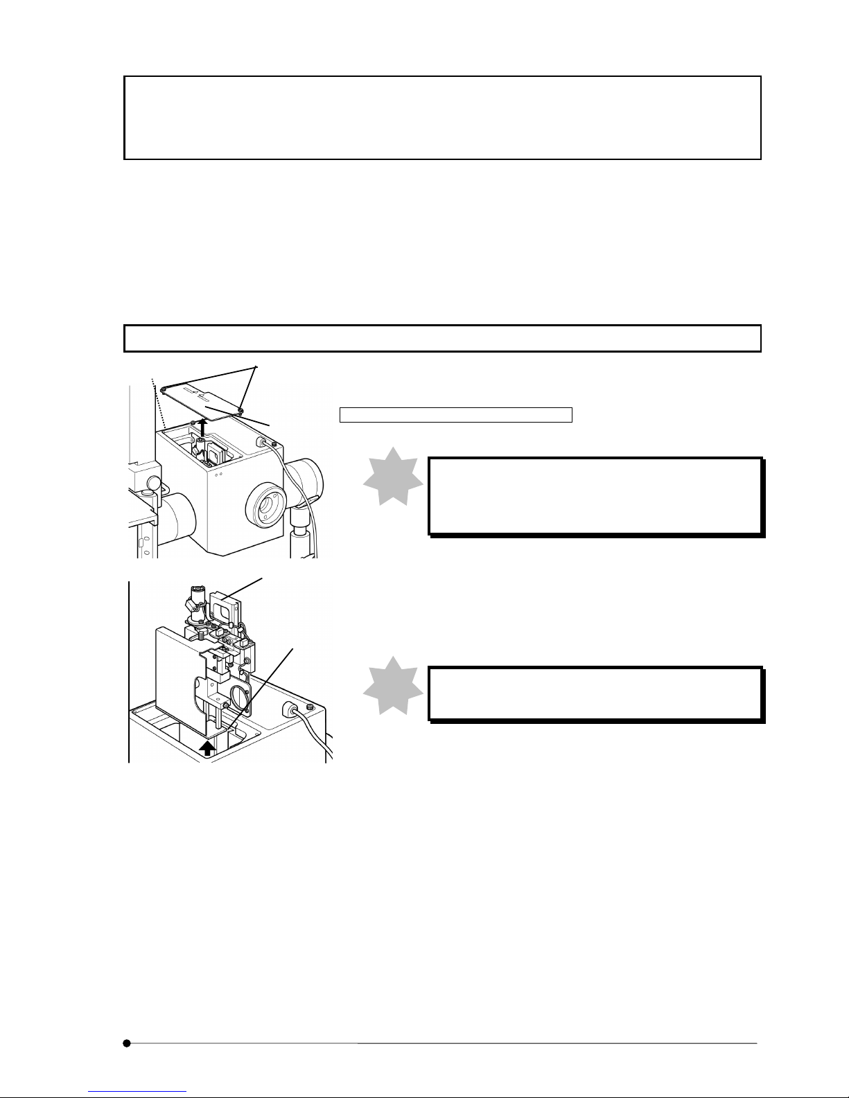
Release of transportation lock for disk unit
When powering up the control box without removing
transportation lock knob, the disk unit may be
damaged.
1. Loosen two fixing screws (2) of access panel (1) on top of disk box,
using dedicated the Allen screwdriver that comes with microscope
frame as accessory and detach the access panel (1).
2. Loosen fixing screw (3) from hole located at left side of disk box,
using the Allen screwdriver and pull up the disk unit (4).
Pull up the disk unit carefully so as not to hit it inside
wall of disk box.
Note
Note
(1)
(2)
(3)
(4)
(9)
Page 8
INTRODUCTION
2
Page
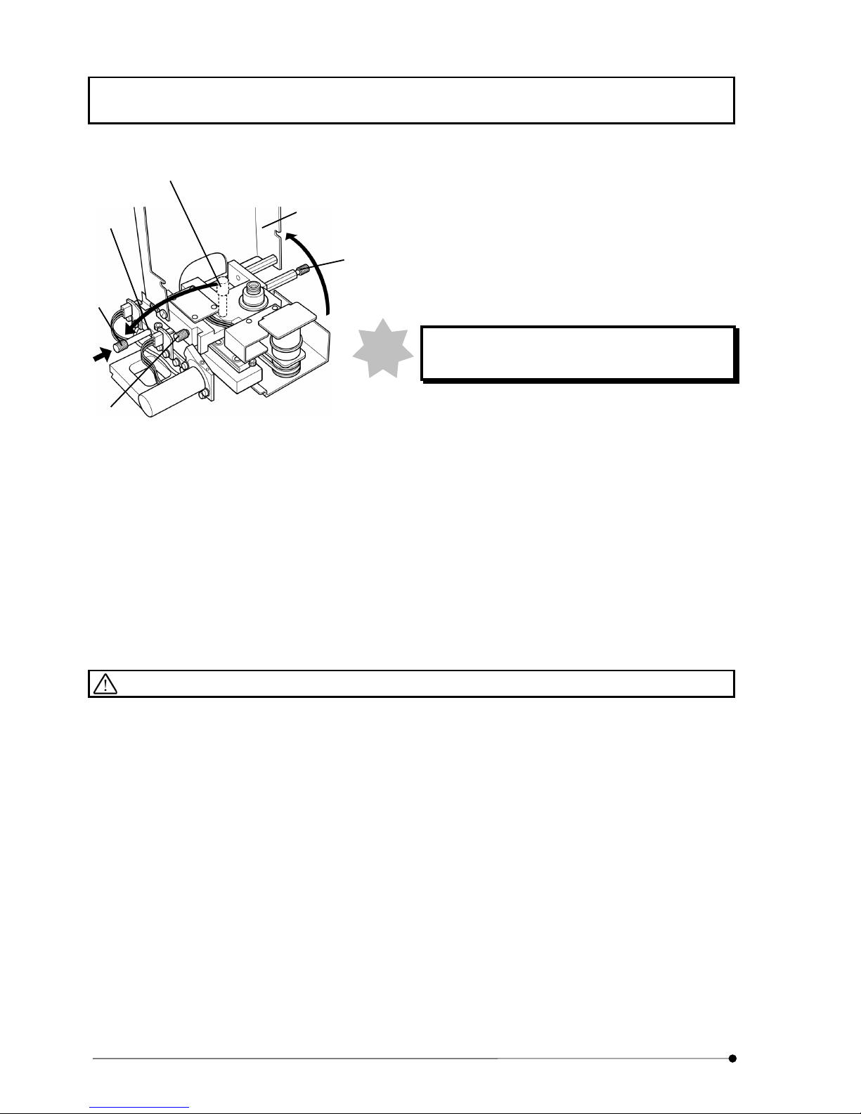
3. Loosen knob (5) of disk unit (at 2 places) and open disk protective
covers (6).
4. Loosen transportation lock knob (7) and remove it from the disk
unit (4).
Install the transportation lock knob you removed to the threaded
hole (8) of disk unit.
The transportation lock knob may be used for re-
transportation. Keep it with care.
When you continue to install disk, see Section 8-13 Disk
installation and change.
5. Return disk protective covers (6) to original position and tighten
knob (5) of disk unit (at 2 places) and fix the covers.
6. Align mount dovetail of disk unit (4) and mount dovetail (9) inside
the disk box and push the disk unit from top until it hits to dead
end.
7. Tighten fixing screw (3) with use of the Allen screwdriver and fix it.
8. Attach access panel (1) on top of disk box and tighten fixing
screws (2) (at 2 places) and fix it.
Safety Caution
l When you change disk, turn power of control box to OFF position and wait for one minute or more until the
turn of disk is completely stopped. The disk turns very rapidly so that they may be a danger to squeeze your
finger.
l When you change mirror unit for camera observation, change it after you turn the power of control box to
OFF position. During the change, it may be a danger to squeeze your finger if you accidentally touch the
changeover switch.
l Do not touch surface of disk with your hand. If the disk is blurred, observation image may be deteriorated.
l Do not touch lamp house mount adapter with your hand when the system is in use. As the adapter is
installed near the lamp house, the surface will get high temperature.
l Do not put power cord in the vicinity of lamp house. Lamp house will be of very high temperature. If power
cord touched the lamp house, the cord may be molten which would cause an electric shock.
Note
(5)
(7)
(6)
(7)
(5)
(8)
Page 9

INTRODUCTION
3
Page
l Do not turn the lamp ON without installing lamp house to microscope. Ultraviolet ray of lamp is hazardous to
your eyes. Do not look at the light from lamp house directly.
l Do not look at excited light directly. When you use microscope, attach ultraviolet ray cutting plate and see
specimen and others through ultraviolet ray cutting plate for sure.
l When you change mirror unit at front side turret and rear side turret, observe the placement to the light path
in order of 1. fluorescent mirror unit and 2. reference mirror (No.1 position at each turret). If reference mirror
were set in front side turret and rear side turret, strong light would be applied to the specimen and it is
dangerous. (Regarding method of changeover for front and rear side turret, refer to Section 3-7
Changeover of mirror unit for visual observation (front side) and 3-10 Changeover of mirror unit for camera
observation (rear side).
Symbol for safety considerations
This system comes with the following symbols.
Understand the meaning of symbol and handle it safely.
Symbol Meaning
Do not touch with your hand as the surface is very hot.
It may cause a burn.
Be careful so as not to entangle your finger with disk or mirror unit for camera
observation.
Please read instruction manual definitely before you use the system.
In case of erroneous handling, it may cause injury of user or damage to
product.
Main switch is ON.
Main switch is OFF.
Page 10
INTRODUCTION
4
Page
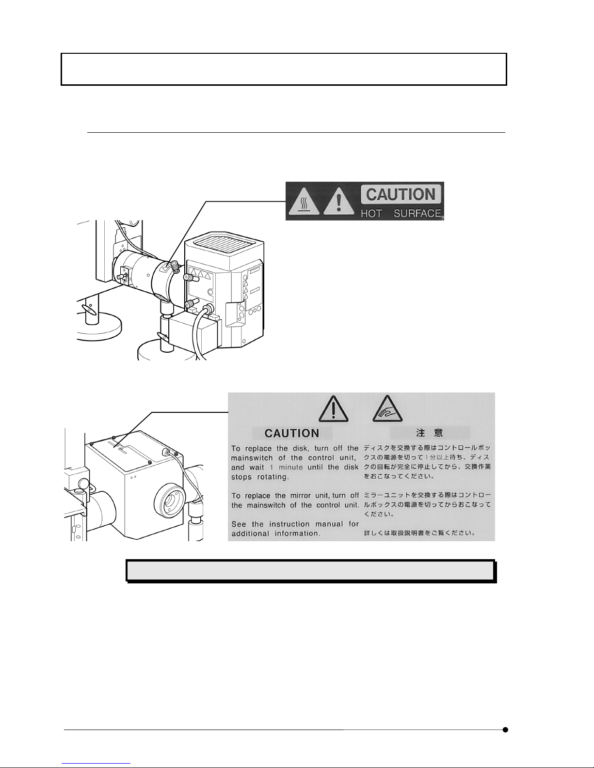
Warning labels
Warning label is attached to the place where caution is particularly required for operation. Observe the
instructions.
Lamp house mount adapter (Hot Surface caution)
Disk box (Entanglement caution)
When warning label is blurred or peeled off, contact our local sales office for change.
Page 11
INTRODUCTION
5
Page
When using the system
l Handle this system with care so as not to give a shock as it is a precision instrument.
l This system requires independent fluorescent mirror unit for visual and camera observation respectively.
Install fluorescent mirror unit for visual observation to front side turret and install fluorescent mirror unit for
camera observation to rear side turret.
l Use high performance fluorescent mirror unit (HQ type) for camera observation in order to get optimum
optical performance.
l The fluorescent mirror unit – DSU-MRFPHQ – that comes with this system as accessory is for camera
observation.
Do not install it to front side turret for visual observation.
l Environment should be of room temperature at 10~35°C with relative humidity at 30~80%.
l Do not disassemble each section in vain as it may cause failure.
l Lamp house will get very hot. When installing, acquire adequate space in vicinity of lamp house (10cm or
more), particularly on top.
Cleanup and storage
l Never put dirt or fingerprint on surface of lens and filter, etc. In case of contamination, use gauze and wipe
out lightly. In case that the dirt or fingerprint does not come off with gauze, then, use mixed liquid (alcohol 3:
ether 7) to put in gauze and wipe out gently.
Liquid like ether or alcohol is very inflammable. Care must be taken when you handle
such liquid against fire and power switch ON-OFF procedure. Particularly, when using
ether or alcohol, pay utmost attention to ventilation of the room.
l When you clean other parts of the system, use a soft cloth dipped with diluted mild detergent to wipe each
section. Do not use organic solvent as it would deteriorate plastic parts or paint.
Caution
l If this system is used in other methods than those described in this manual, the safety is not guaranteed
and it may cause a failure or damage to the system. Use this system in accordance with instruction manual.
Page 12
INTRODUCTION
6
Page
Manual conventions
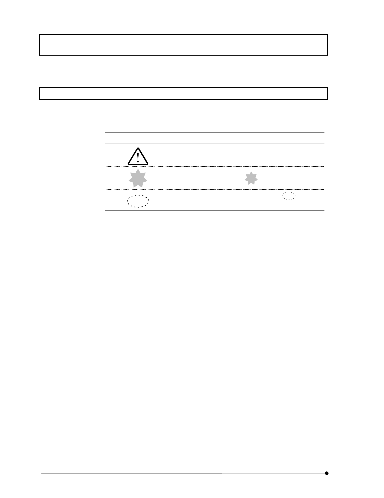
This manual describes with use of the following manual conventions.
² Conventions of note, reference and point
Conventions Description
Indicates note to prevent injury of user and damage of product
(including home furniture, etc.).
Note
Typical note is indicated with
Note
.
Tip
Advice or hint for reference is indicated with
Tip
.
Page 13
II..
Page 14

Page 15

SYSTEM OUTLINE / Principle
I.
System Outline
I.
1-1
Page
1 SYSTEM OUTLINE
Attaching this system to a microscope, it comprises a confocal microscope system without laser, but with use of
a white light source. It acquires a high contrast image through resolution enhanced in light axis direction very
rapidly.
In addition, Olympus motorized microscopes IX81, BX61WI, BX61 or BX62 and their related motorized units
may be controlled through a 3rd party software, which is designed for observation by CCD camera.
And the combination of such the software and the microscope may enable 3 dimensional observation, time-
lapse observation and so on.
The software controls changeover of confocal/non-confocal mode, ND filter synchronized to confocal or non-
confocal mode and filter cube inside the disk box in conjunction with motorized focusing control of motorized
microscope and thus, by changing wavelength through Z-drive of focusing control, it acquires images for myriad
observation.
1-1 Principle
Light emitted from light source of mercury or xenon
reflects at fluorescent mirror and enters rotary disk
in light path. The rotary disk has a pattern of linear
lines that provides the effect equivalent to pin hole
by high speed rotation. Light that passes through
the pattern further passes through objective lens
and goes to the specimen. Fluorescence emitted
from the specimen passes through the objective
lens again and forms an image on the rotary disk.
Among image formed, a portion of light that is in
focus will pass through the disk and, CCD camera
captures the image and the specimen image will be
displayed on the monitor.
Light
source
ND Filter
Objective lens
Imaging lens
Imaging lens
Rotary disk
CCD Camera
Monitor
Specimen
Light
illuminator
Fluorescent
Mirror unit
Disk box
Camera adapter
Illumination
tube
Page 16

SYSTEM OUTLINE / Features
I.
System Outline
I.
1-2
Page
1-2 Features
● Confocal disk employed enables to acquire image of confocal effect.
● As while light source such as mercury or xenon is used as a light source instead of
laser, excited light of various wavelengths can be used by combination of excitation
filter and cube.
● In case of non-confocal observation by displacing the disk from light path, an image
of deep focal point without confocal effect can be acquired. In case of confocal
observation by placing the disk in light path, a sharp image of shallow focal point
can be acquired. Changeover of confocal to non-confocal can be done very easily.
Page 17
SYSTEM OUTLINE / System Configuration
I.
System Outline
I.
1-3
Page
1-3 System Configuration
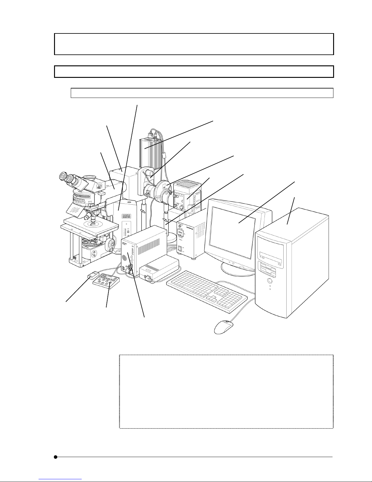
1-3-1 In case of BX series
Figure of BX series System Configuration
When you use this system in conjunction with microscope, you cannot integrate the
following units:
Motorized condenser (U-UCD8A) and motorized reflected light fluorescence (BX-RFAA
and BX-RLAA).
Motorized filter wheel (U-FWT and U-FWO)
When you integrate motorized revolving nosepiece, connect control box (IX2-UCB) with
use of connecting cable (U-REMMT).
Monitor
Computer
Cooled CCD Camera
Control box
(IX2-UCB)
DSU motor drive board
(DU-MTDRV) attached
Hand switch
(U-HSTR2)
Lamp
House
Microscope
(BX51, BX52, BX61, BX62,
BX51WI or BX61WI)
Light illuminator
for DSU BX
(DU-RFABX)
DSU Disk box
(DU-DBIX)
Motorized filter wheel
(U-FWR)
Stand for DSU BX
(DU-STBX)
DSU Hand switch
(DU-HSW)
Shutter and
Filter wheel
Page 18
SYSTEM OUTLINE / System Configuration
I.
System Outline
I.
1-4
Page
Table of Instruction Manuals for Modules to be integrated
Instruction Manual Module name
SYSTEM MICROSCOPE BX51/BX52
MOTORIZED SYSTEM
MICROSCOPE
BX61/BX62
FIXED-STAGE UPRIGHT
MICROSCOPE
BX51WI
FIXED-STAGE MOTORIZED
UPRIGHT MICROSCOPE
BX61WI
CONTROL BOX FOR IX2 HAND
SWITCH
IX2-UCB
U-HSTR2
Cooled CCD Camera Manual for Cooled CCD Camera you may use
Computer/Monitor Manual for computer you may use
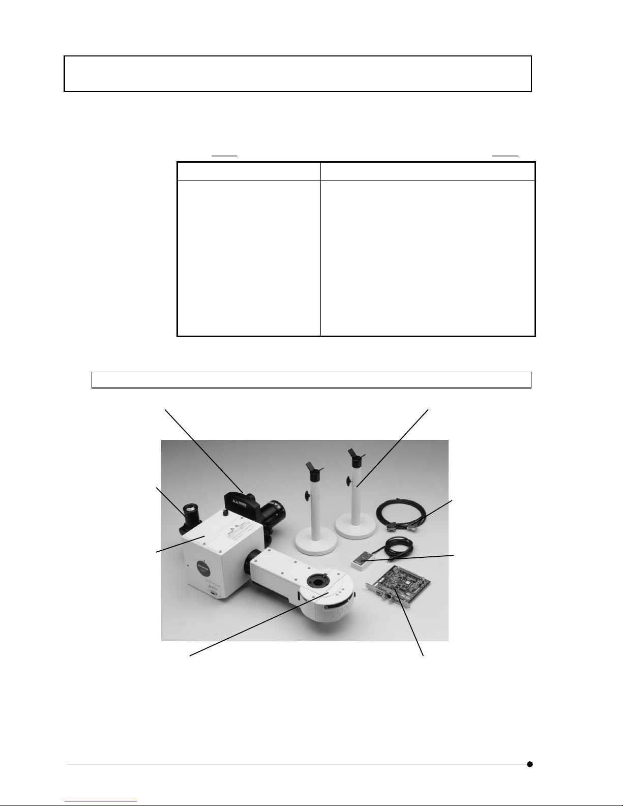
1-3-2 BX-DSU
BX-DSU includes the units, which have a mark "*" in its description on the above picture.
* DSU Hand switch
(DU-HSW)
* Disk control cable
* DSU motor drive board
(DU-MTDRV)
* DSU Disk box
(DU-DBIX)
DSU C-mount adapter
(DSU-CAD)
* Stand for DSU BX
(DU-STBX)
* Motorized filter wheel
(U-FWR)
* Light illuminator for DSU BX
(DU-RFABX)
Page 19
SYSTEM OUTLINE / System Configuration
I.
System Outline
I.
1-5
Page
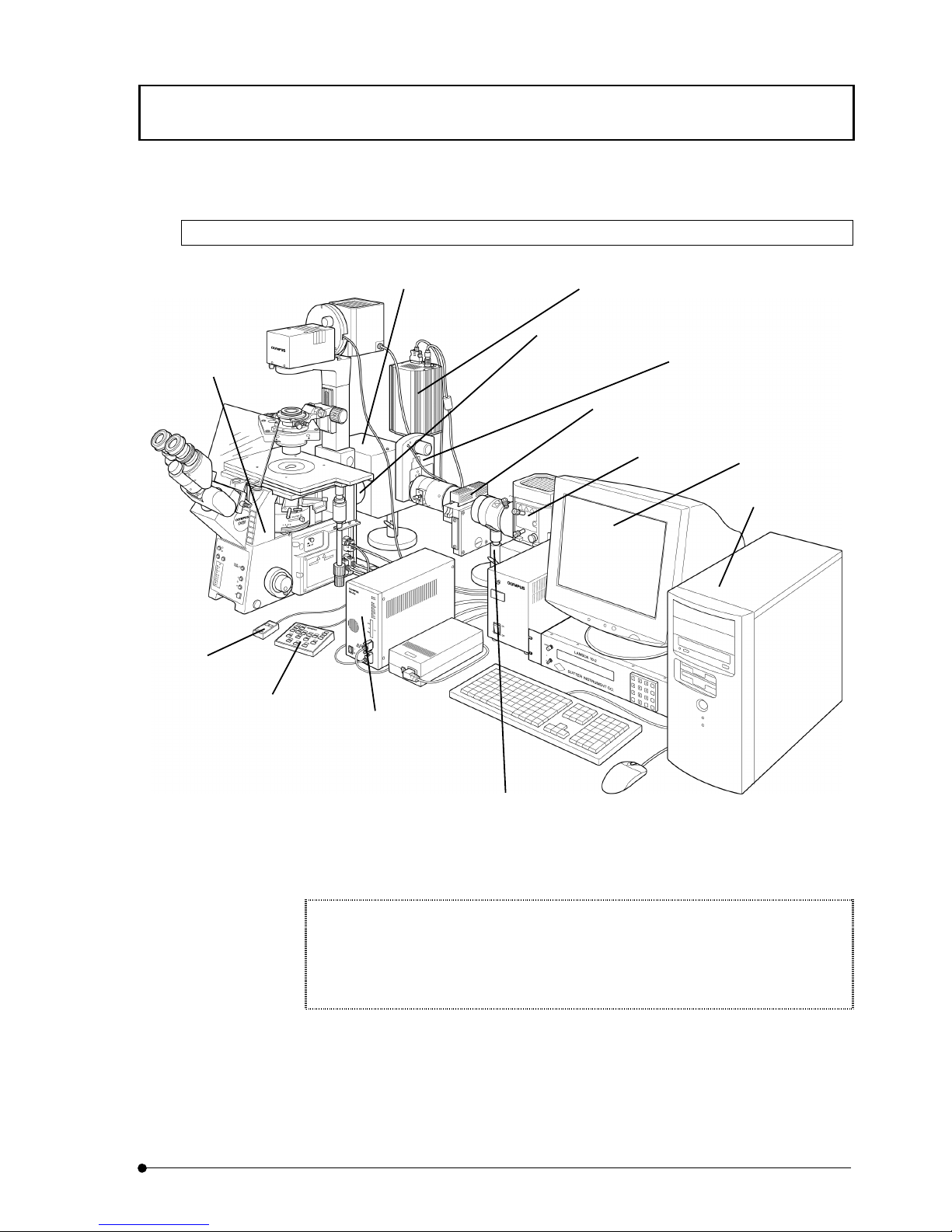
1-3-3 In case of IX series
Figure of IX Series System Configuration
When you use this system in conjunction with microscope (IX71 or IX81), you cannot
integrate with the following units:
Motorized fluorescent mirror unit cassette (IX2-RFACA) and motorized filter wheel (U-
FWT and U-FWO).
Monitor
Computer
Cooled CCD Camera
Control box
(IX2-UCB)
DSU motor drive board
(DU-MTDRV) attached
Hand switch
(U-HSTR2)
Shutter and
Filter wheel
Lamp
House
Microscope
(IX71, IX81)
Light illuminator
for DSU IX
(DU-RFAIX)
DSU Disk box
(DU-DBIX)
Motorized filter wheel
(U-FWR)
Stand for DSU IX
(DU-STIX)
DSU Hand switch
(DU-HSW)
Page 20
SYSTEM OUTLINE / System Configuration
I.
System Outline
I.
1-6
Page
Table of Instruction Manuals for Modules to be integrated
Instruction Manual Module name
INVERTED RESEARCH
MICROSCOPE
IX71
MOTORIZED INVERTED
RESEARCH MICROSCOPE
IX81
CONTROL BOX FOR IX2 HAND
SWITCH
IX2-UCB
U-HSTR2
Cooled CCD Camera Manual for Cooled CCD Camera you may use
Computer/Monitor Manual for computer you may use
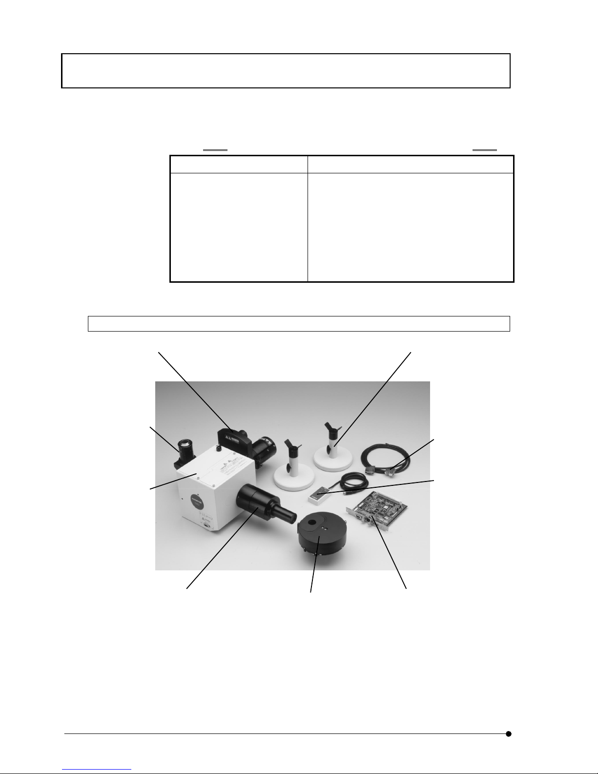
1-3-4 IX2-DSU
IX2-DSU includes the units, which have a mark "*" in its description on the above picture.
* DSU motor drive board
(DU-MTDRV)
* DSU Hand switch
(DU-HSW)
* Disk control cable
* DSU Disk box
(DU-DBIX)
DSU C-mount adapter
(DSU-CAD)
* Stand for DSU IX
(DU-STIX)
* Motorized filter wheel
(U-FWR)
* Light illuminator for DSU IX
(DU-RFAIX)
* Mirror unit cassette
Page 21

IIII..
Page 22

Page 23
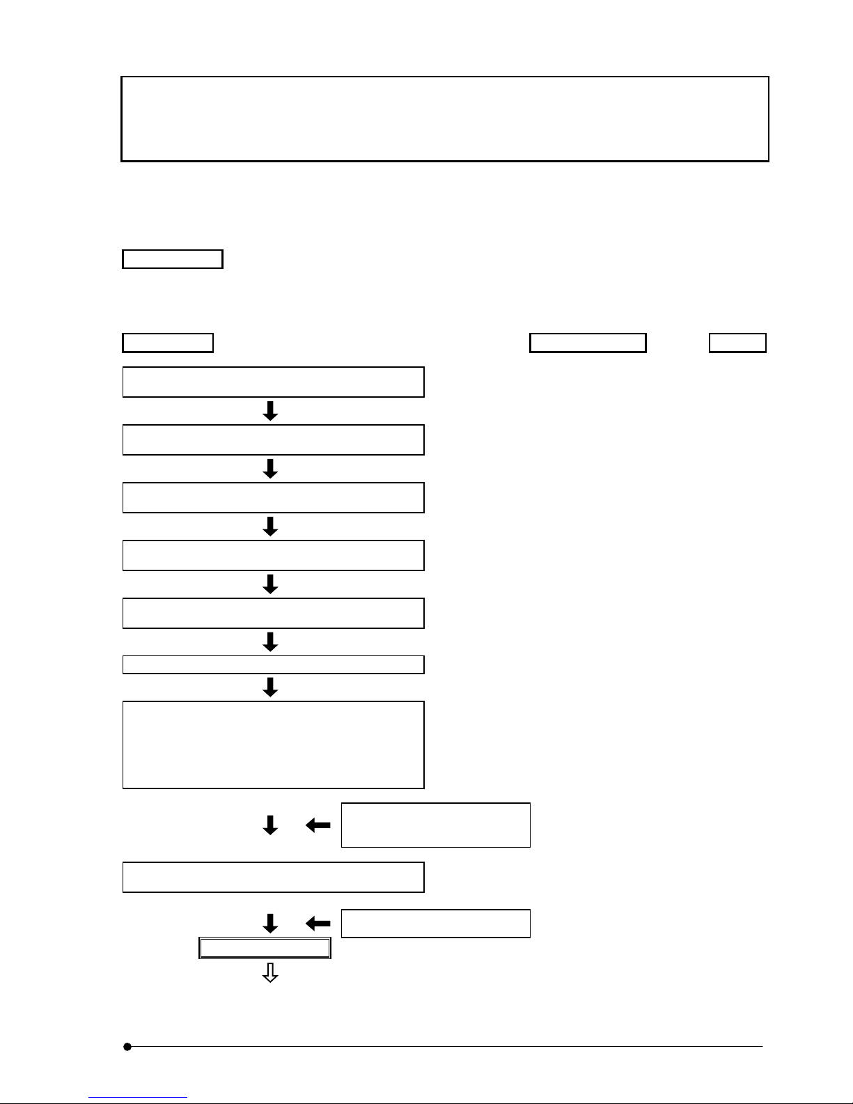
SUMMARY OF OBSERVATION PROCEDURES
II .
DSU
II .
2-1
Page
2 SUMMARY OF OBSERVATION
PROCEDURES
This section describes procedures for fluorescent observation by visual method followed by camera observation
by confocal mode.
Preparation
•Install fluorescent mirror unit and objective lens applicable to observation method.
•Do centering of mercury lamp or xenon lamp.
•Bring camera in focus.
Procedures
Where Ref.
Turn power switch of each system to ON position
and do initialization.
.......................... Power switch of each
system
3-5
Turn power switch of lamp to ON position and wait
until arc is stabilized. (5 to 10 minutes).
.......................... Main switch of lamp power 3-5
Set specimen on stage.
.......................... Lateral/Longitudinal feed
handle
-
Turn turret of front side and insert visual mirror unit
that fits to specimen into light path.
.......................... Visual mirror unit (front
side)
3-7
Turn turret of rear side and insert No.1 reference
mirror into light path
.......................... Camera mirror unit (rear
side) change button
3-10
Displace disk from light path.
.......................... Disk IN/OUT button 3-8
Put objective lens in light path and open shutter to
bring the specimen in focus.
.......................... Objective lens change
button, revolving
nosepiece, shutter
open/close knob or Electric
shutter or focusing handle
or coarse/fine handle
3-6
3-9
Adjust light intensity with use of
ND filter to put in or remove
from light path.
Filter change button 3-11
Adjust entire field of view to be uniformly bright.
.......................... Collector lens focusing
knob
3-12
Adjust field iris diaphragm.
Field iris diaphragm lever 3-12
Visual observation
(To next page)
Page 24
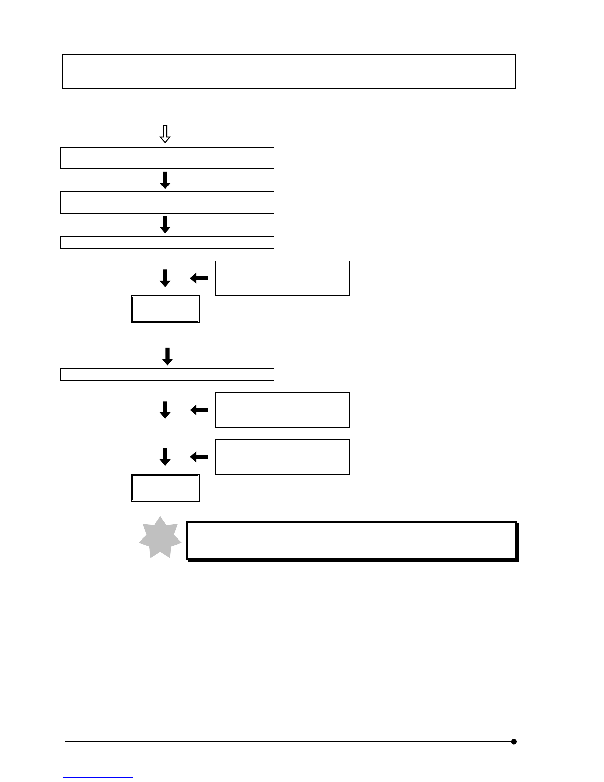
Summary of observation procedures
II .
DSU
II .
2-2
Page
(From previous page)
Turn turret of rear side and put camera mirror unit
that suits to the specimen.
.......................... Camera mirror unit (rear
side) change button
3-10
Turn turret of front side and put No.1 reference
mirror into light path
.......................... Visual mirror unit (front
side)
3-7
Set camera setting for observation.
.......................... Control of camera -
Adjust light intensity with use of
ND filter to put in or remove
from light path.
Filter change button
Camera
observation
Put disk into light path.
.......................... Disk IN/OUT button 3-8
Adjust light intensity with use of
ND filter to put in or remove
from light path.
Filter change button
If necessary, set camera setting
to meet with observation.
Control of camera
Confocal
observation
During observation, use shutter for short interruption of observation.
Note
Page 25

DETAILS OF EACH OPERATION / General Precaution for observation
II .
DSU
II .
3-1
Page
3 DETAILS OF EACH OPERATION
3-1 General Precaution for observation
1. Verify that input voltage/frequency to be used is within the range of that described
in identification plate of the system.
2. Verify that power cord as well as connecting cord is securely connected.
3. In case that transmitted light phase contrast observation or transmitted light DIC
(Differential Interference Contrast) observation only is required, make one place
where fluorescent mirror unit is not attached and do observation.
4. Use field iris diaphragm, squeezing it until it circumscribes to the filed of view and,
in case that it is out of center, adjust it with use of the Allen screwdriver.
5. Use immersion oil for objection lens of immersion type.
6. When you use objective lens of LCPlanFI series, attach a correction cap that
compensates thickness of container used for objective lens that is used for
observation. See instruction manual for IX2 series for kinds of correction caps
available.
7. Objective lens, UPlanApo40x (cover glass thickness offset 0.11~0.23), PlanApo40x
(0.11~0.23), UApo40x3/340 (0.11~0.23), UPlanApo60xW3 (0.15~0.20),
LCPlanFI40x (0~2.5) and 60x (0~2.5), all come with a correction ring; can
compensate deterioration of resolution due to variance of cover glass thickness.
Correction method
While turning correction ring, seek the position by adjusting
focus with use of fine-tuning handle and get best possible
resolution.
8. When a pause is required frequently during observation, use shutter (manual or
electric shutter).
(If mercury lamp is turned ON-OFF so frequently, it may deteriorate life of lamp).
9. Note to color deterioration on specimen
In case that observation is done with use of objective lens of high power, color
deterioration on specimen may occur earlier and contrast of fluorescent image may
be deteriorated. In such case, the color deterioration may defer if intensity of
excited light is lowered to a certain extent and a good fluorescent image may be
acquired. Use of ND filter is recommended to lower intensity of the excited light if it
does not bother the observation. Alternatively, use shutter so as not to apply light
source to specimen so often than it is necessary. Moreover, it can defer the color
deterioration if anti-color deterioration agent commercially available (DABCO) is
used. Particularly, it is recommended that anti-color deterioration agent is used with
high power observation.
Page 26
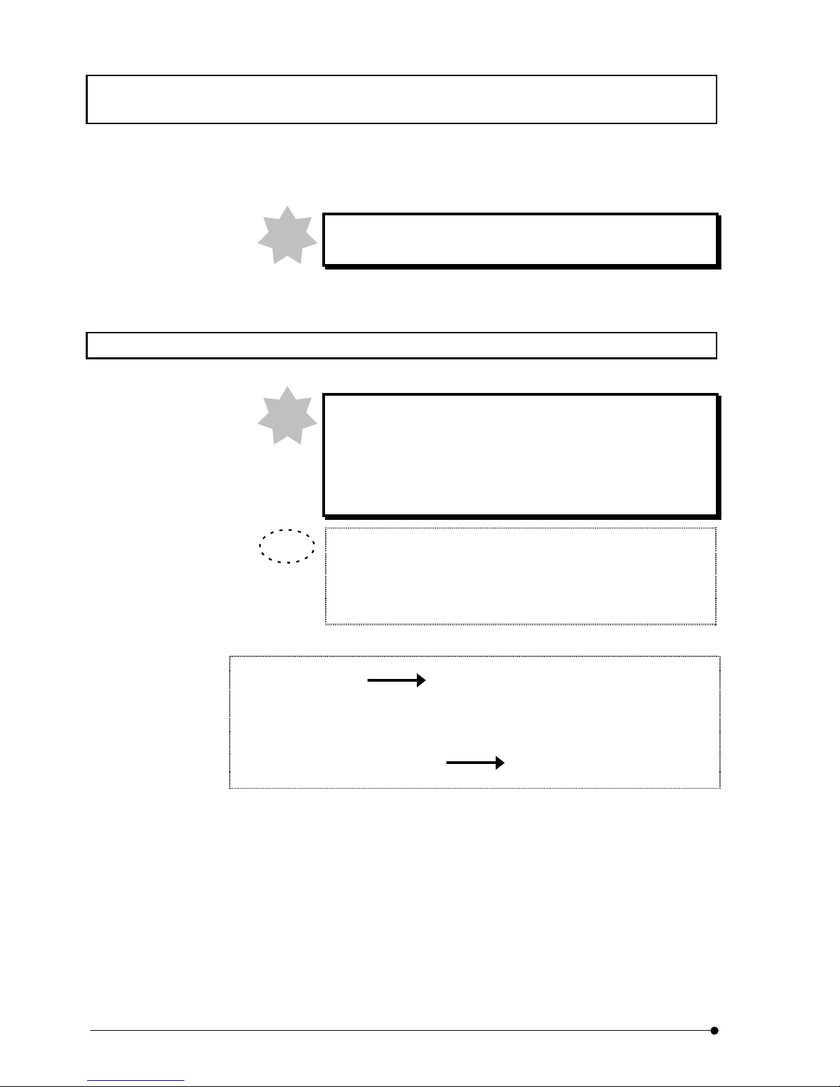
DETAILS OF EACH OPERATION / Selection of fluorescent mirror unit
II .
DSU
II .
3-2
Page
Be careful that specimen of certain kind cannot use anti-color
deterioration agent.
3-2 Selection of fluorescent mirror unit
Select fluorescent mirror unit that has excitation to meet with coloring matter.
Do not use fluorescent mirror unit in combination with brightfield
of view mirror unit (U-MBF3). U-MBF3 is very bright and it may
hurt your eyes. If for any reason the mix use of mirror units is
required, use U-MBFL3 that ND filter is built in or insert ND filter of
3%.
Note to excitation bandwidth
A few sets of excitation filters combined for different bandwidth are
available. Typically, a set of wide bandwith (W) is used but, in case of
the followings, the use of a separate set may be better.
(1) In case that brightness of fluorescence is dark
(B,G excitation only) Change to super wide bandwidth (SW)
(In case of SWB2, fluorescence that comes from
substance other than fluorescent coloring matter may
become stronger.)
(2) In case fluorescence that comes from substance other than
fluorescent coloring matter is strong Change to narrow bandwidth (N)
(Brightness of fluorescence becomes slightly darker.)
Note
TIP
Note
Page 27
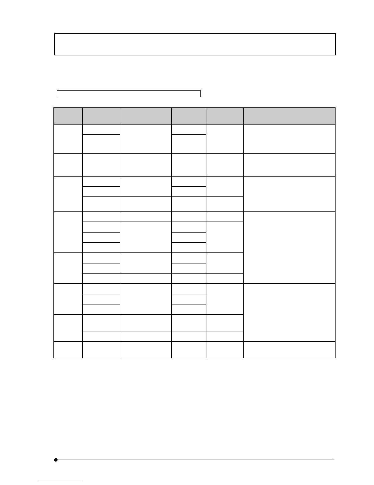
DETAILS OF EACH OPERATION / Selection of fluorescent mirror unit
II .
DSU
II .
3-3
Page
Table of combination for mirror unit and dichroic mirror filter
Excitation
Method
Mirror Unit Dichroic Mirror
Excitation
Filter
Barrier Filter Fluorochrome
U-MWU2 BP330-385
U
U-MNU2
DM400
BP360-370
BA420
• Auto fluorescence observation
• DAPI Dyeing: DNA
• Hoechest 33258, 33342 Dyeing:
Chromosome
V U-MNV2 DM455 BP400-410 BA455
• Catecholamine observation
• serotonin observation
• tetracycline Dyeing: Bone, Teeth
U-MWBV2 BP400-440
U-MNBV2
DM455
BP420-440
BA475
BV
U-MCFPHQ DM450 BP425-445 BA460-510
• quinacrine, quinacrine mustard
Dyeing: Chromosome
• thioflavine S Dyeing: lymph cell
• acriflavine Dyeing: Nucleic acid
• CFP use
U-MGFPHQ DM485 BP460-480 BA495-540
U-MWB2 BP460-490
U-MNB2 BP470-490
B
U-MSWB2
DM500
BP420-480
BA520IF
U-MWIB2 BP460-490
U-MNIB2
DM505
BP470-490
BA510IF
IB
U-MYFPHQ DM505 BP490-500 BA515-560
• FITC Dyeing: Fluorescent
antibody test
• acridine orange Dyeing:DNA, RNA
• auramine Dyeing: TB bacteria
• EGFP, S65T, RSGFP use
• YFP use
U-MWG2 BP510-550
U-MNG2 BP530-550G
U-MSWG2
DM570
BP480-550
BA590
DSU-
MRFPHQ
DM560 BP535-555 BA570-620
IG
U-MWIG2 DM565 BP520-550 BA580IF
• rhodamine, TRITC Dyeing:
Fluorescent antibody test
• propidium iodide Dyeing: DNA
• RFP use
IY U-MWIY2 DM600 BP545-580 BA610IF
texas red Dyeing: Fluorescent
antibody test
Page 28
DETAILS OF EACH OPERATION / Selection of fluorescent mirror unit
II .
DSU
II .
3-4
Page
Color Separation Filter Combinations
Excitation
Method
Mirror Unit Dichroic Mirror
Excitation
Filter
Barrier Filter Fluorochrome
U U-MNUA2 DM400 BP360-370 BA420-460
Observation of U-excited coloring
matter only when Dyeing U-excited
coloring matter and multi-Dyeing of
FITC.
U-MWIBA2 BP460-490
IB
U-MNIBA2
DM505
BP470-490
BA510-550
Observation of B-excited coloring
matter only when Dyeing B-excited
coloring matter or multi-Dyeing
TRITC or texas red.
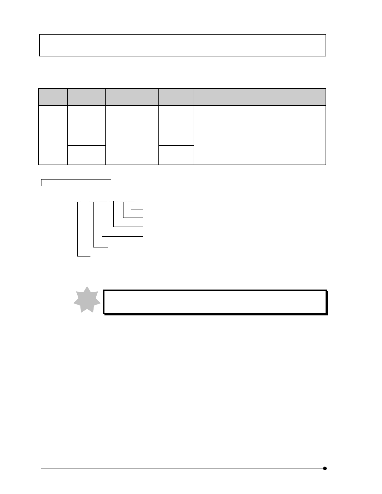
Meaning of mirror unit name (Except HQ type)
Type
A
: For Color Separation
Excitation (U, V, BV, B, IB, G, IG, IY)
Bandwidth SW: Ultra wide band W: Wide band N:
Mirror unit
Universal
U - M N IB A 2
U-MGFPHQ and DSU-MRFPHQ come with this system as standard accessories.
As fluorescent mirror unit for camera observation, use HQ type.
DSU-MRFPHQ – accessory of this system – is dedicated for camera observation.
Note
Page 29
DETAILS OF EACH OPERATION / Table of Combination – Objective lens to each observation and applicable
disk
II .
DSU
II .
3-5
Page
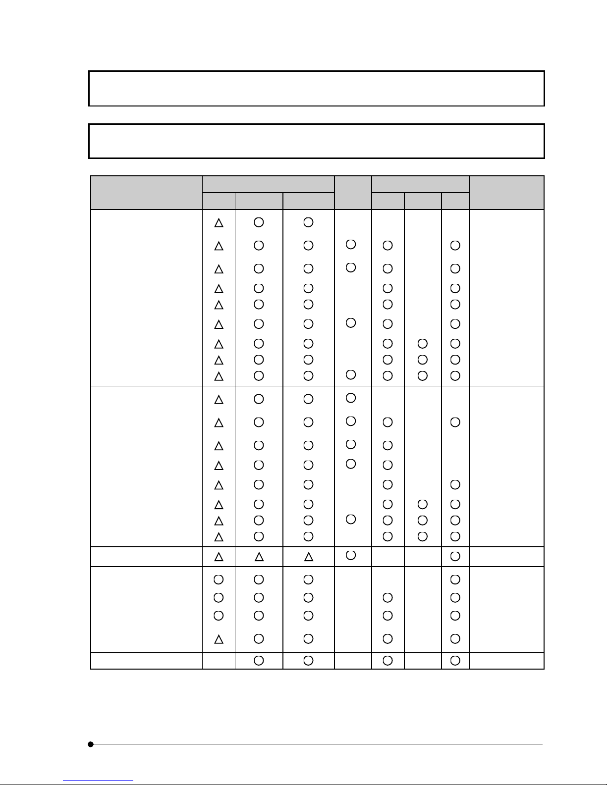
3-3 Table of Combination – Objective lens to each observation and
applicable disk
Reflected light fluorescence Differential interference
Objection lens
340 U, V, BV B, IB, G, IY
Phase
contrast
BX2 BX2WI* IX2
Applicable disk
UPlanApo 4x ––––
DSU-D1
DSU-D2
10x
*
–
DSU-D1
DSU-D2
20x
*
–
DSU-D1
DSU-D2
20xO – – DSU-D1
40x – – DSU-D3
40xOI3
*
–
DSU-D1
DSU-D2
60xW3 – DSU-D3
60xW/IR3 – DSU-D3
100xOI3
*
DSU-D4
UPlanFl 4x
*
–––
DSU-D1
DSU-D2
10x
*
–
DSU-D1
DSU-D2
20x
*
––
DSU-D1
DSU-D2
40x
*
– – DSU-D3
40xO – –
DSU-D1
DSU-D2
60xOI3 – DSU-D3
100xO3
*
DSU-D4
100xOI3 – DSU-D4
CPlanFl 10xPh
*
––
DSU-D1
UApo 20x3/340 –––
DSU-D1
DSU-D2
40x3/340 – – DSU-D3
40xOI3/340 – –
DSU-D1
DSU-D2
40xW3/340 – –
DSU-D1
DSU-D2
PlanApo 60xO3 – – – DSU-D3
Page 30
DETAILS OF EACH OPERATION / Table of Combination – Objective lens to each observation and applicable
disk
II .
DSU
II .
3-6
Page
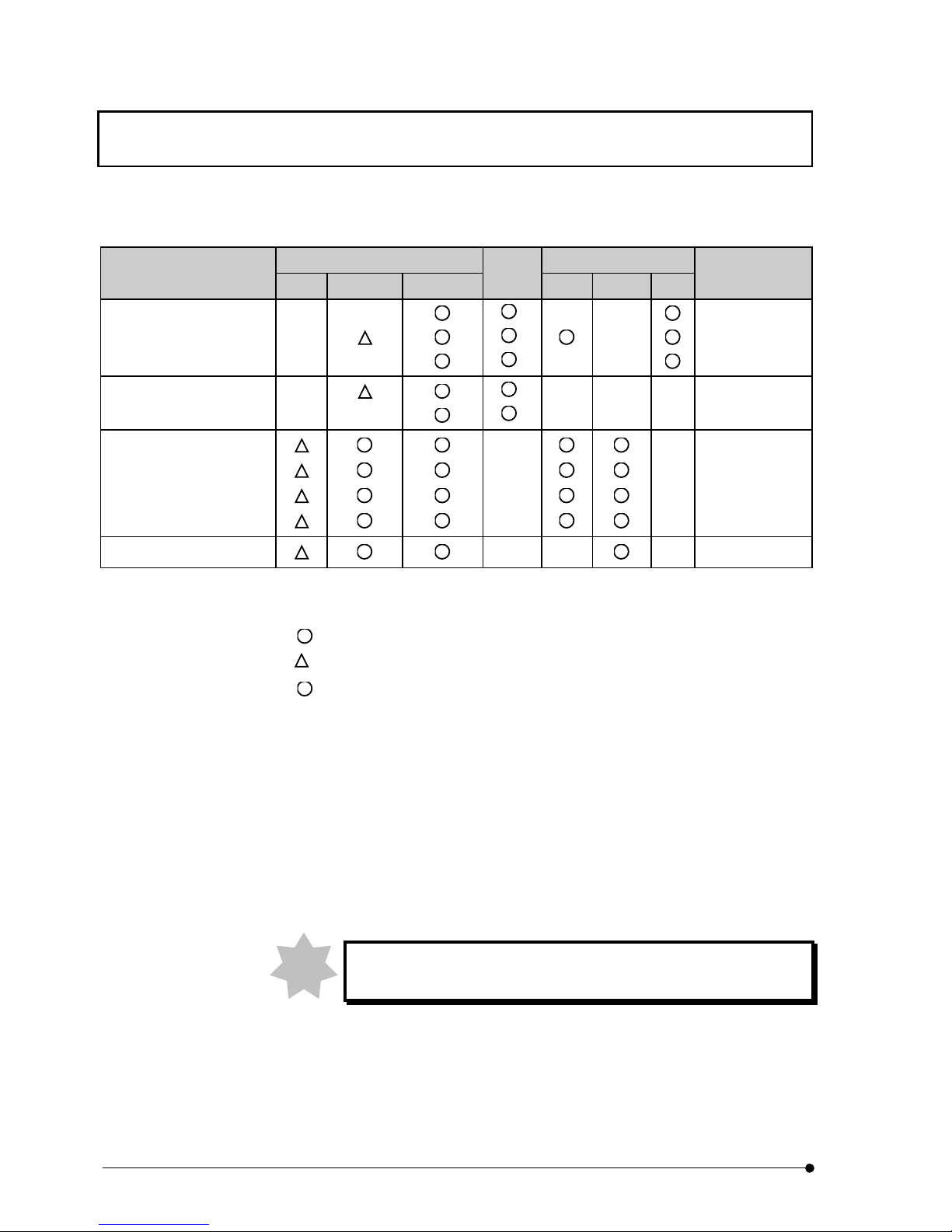
Reflected light fluorescence Differential interference
Objection lens
340 U, V, BV B, IB, G, IY
Phase
contrast
BX2 BX2WI* IX2
Applicable disk
LCPlanFl 20x – –
*
––
DSU-D3
40x –
*
– DSU-D4
60x – –
*
––
DSU-D4
LCAch 20x –
*
––– DSU-D3
40x – –
*
––– DSU-D4
LUMPLFL 40xW – –DSU-D3
40xW/IR – –DSU-D3
60xW – –DSU-D4
60xW/IR – –DSU-D4
XLUMPLFL 20xW –– –DSU-D5
* BX2WI can be used for differential interference contrast observation - the same combination as BX2 - provided
that it uses U-UCD8.
: Useable combination.
: Useable combination but it gets dark.
* : For phase contrast observation, objective lens for phase contrast is required.
– : Not useable or no applicable objective lens available.
DSU-D1 : Standard, for thick specimen
DSU-D2 : Standard, for thin specimen (comes with this system as accessory)
DSU-D3 : For WI 40x
DSU-D4 : For WI Standard 60x
DSU-D5 : For XLUMPLFL20x only
(DSU-D1/DSU-D2 should be used according to thickness of specimen.)
Plastic container (petri dish or flask) is not useful for differential
inteference observation.
Note
Page 31
DETAILS OF EACH OPERATION / Assignment of operating buttons on body (BX61, BX62 or BX61WI only)
II .
DSU
II .
3-7
Page
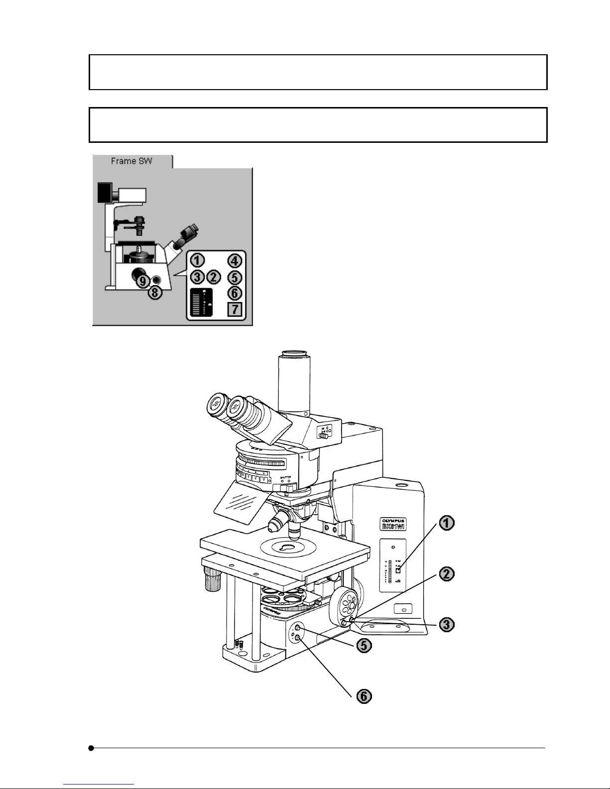
3-4 Assignment of operating buttons on body (BX61, BX62 or BX61WI
only)
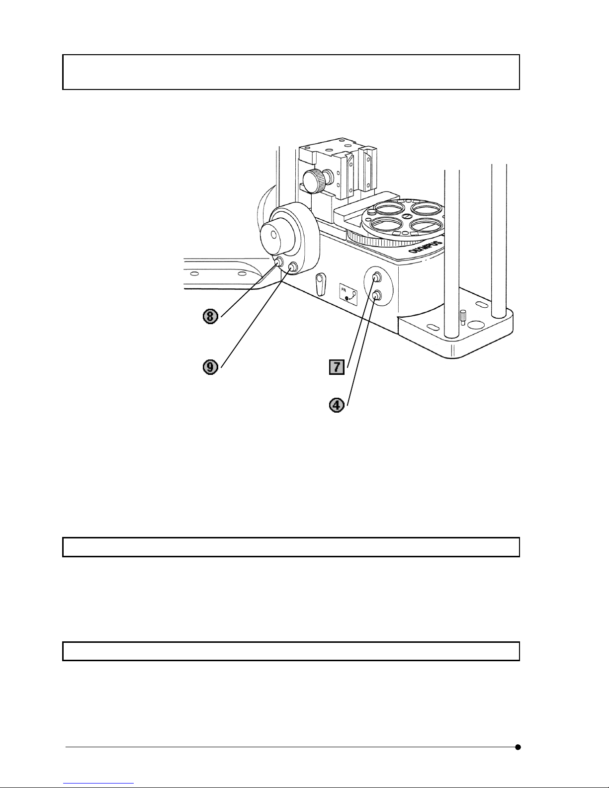
When IX2-BSW software boots up, microscope IX and its operation
buttons will be displayed on tab called [Frame SW]. When you use
BX61, BX62 or BX61WI, however, microscope does not appear.
Assignment of operating buttons for microscope – BX61, BX62 or
BX61WI as well as operating buttons on [Frame SW] tab are as
follows.
Not used
Focus UP button
Focus DOWN button
Brightness adjusting button (getting bright)
Brightness adjusting button (getting dark)
Page 32
DETAILS OF EACH OPERATION / Powering up
II .
DSU
II .
3-8
Page
*1In case that control box (IX2-UCB) is of type 1, the identifying plate indicates IX2-UCB.
*
2
In case that control box (IX2-UCB) is of type 2, the identifying plate indicates IX2-UCB-2.
3-5 Powering up
1. Switch on the control box.
2. Switch on the lamp.
3. Switch on CCD camera.
3-6 Focusing
Use coarse/fine handle to bring the specimen in focus. In case of motorized microscope,
use focus handle unit or focus operating button on body to bring the specimen in focus.
Lamp ON/OFF button
Lamp set*
1
Not used*
2
F/C Change button
Focus retreat button
Page 33
DETAILS OF EACH OPERATION / Changeover of visual mirror unit (front side)
II .
DSU
II .
3-9
Page
3-7 Changeover of visual mirror unit (front side)
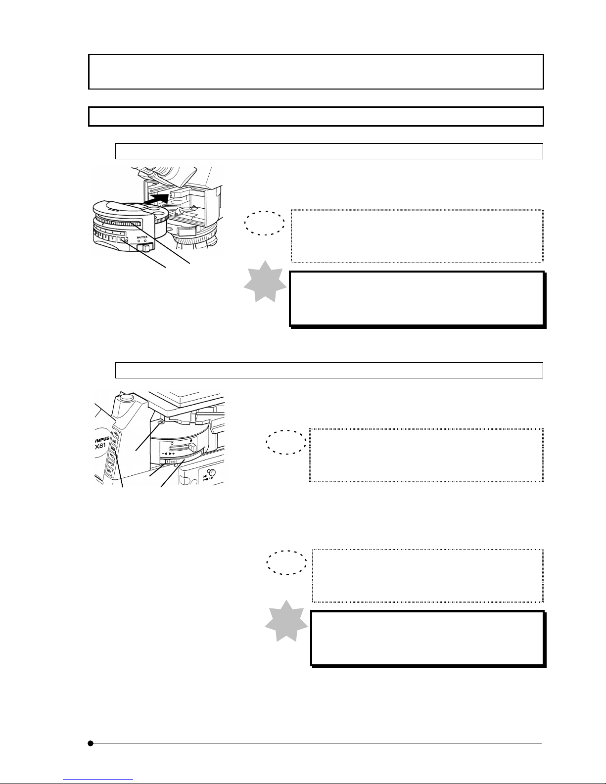
3-7-1 In case of BX
Turn turret (1) located in front of light illuminator and insert mirror unit
desired or reference mirror into light path. Reference mirror to insert into
light path is normally put in No. 1 for use of camera observation.
In case that mirror unit name is put in a pocket of identifying
plate (2) of microscope frame, you can verify the name of mirror
unit.
When you insert reference mirror put in No.1 into light
path, verify that rear side turret is set to fluorescent mirror
unit.
3-7-2 In case of IX
1. Look at mirror unit indication (1) on surface of mirror unit cassette or
look at indication (2) at right side of turret and verify mirror unit
number that is currently inserted into light path.
In case that mirror unit name is put in a pocket of
identifying plate (3) of microscope frame, you can verify
the name of mirror unit.
2. Turn turret (4) so as to bring number of mirror unit that is to be used
in indicator of mirror unit cassette (1) or (2) and fix it at click position.
Reference mirror to insert into light path is put in No. 1 for use of
camera observation.
Turning turret in [+] direction, the number changes in
order of "1→2→3→4→5→6→1", and in [−] direction, it
changes in order of "1→6→5→4→3→2→1".
When you insert reference mirror put in No.1 into light
path, verify that rear side turret is set to fluorescent
mirror unit.
(1)
TIP
TIP
(1)
(2)
(3)
(4)
TIP
(2)
Note
Note
Page 34
DETAILS OF EACH OPERATION / Disk IN/OUT
II .
DSU
II .
3-10
Page
3-8 Disk IN/OUT
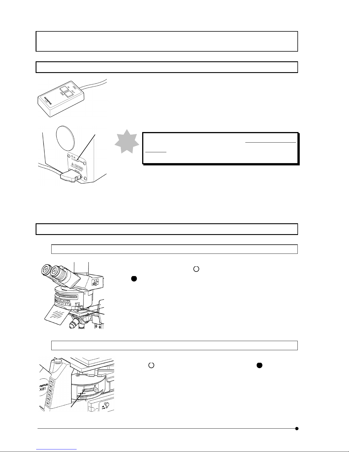
When you wish to insert disk into light path, press left IN button of DSU hand
switch. Likewise, press right OUT button so that the disk would be displaced from
light path.
When disk comes into light path, LED (1) located at left side of
disk box would light in green and, when it is displaced from
light path, the LED would go off.
3-9 Shutter OPEN/CLOSE
3-9-1 In case of BX
When shutter knob (1) located at right lower side of turret in front of light
illuminator is moved left to mark
side, the shutter would open, and right to
mark
side, it would close.
3-9-2 In case of IX
When shutter knob (1) located at right side of visual mirror unit is moved
left to
side, the shutter would open, and right to side, it would
close.
(1)
(1)
Note
(1)
Page 35
DETAILS OF EACH OPERATION / Changeover of camera mirror unit (rear side)
II .
DSU
II .
3-11
Page
3-10 Changeover of camera mirror unit (rear side)
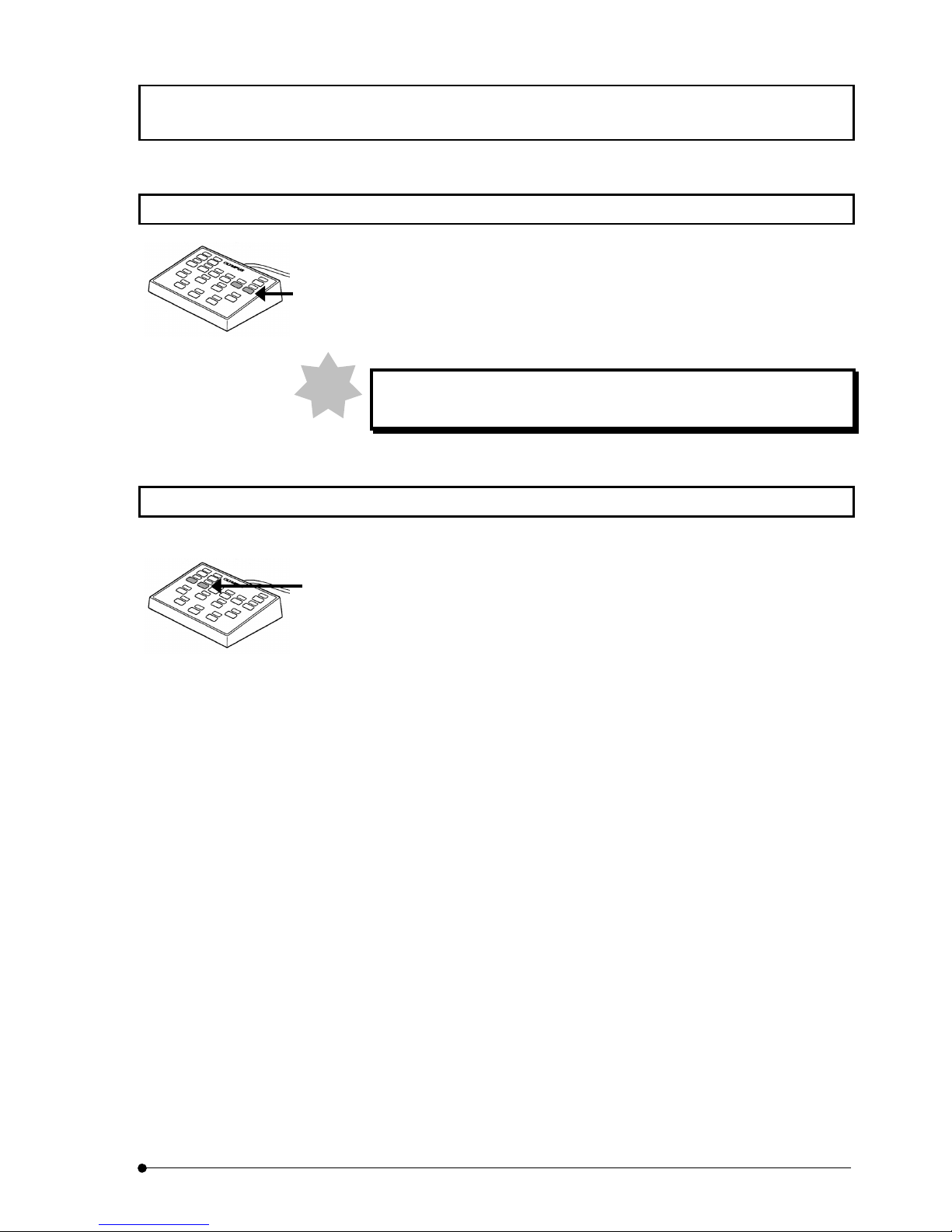
Press button on hand switch to turn the turret and insert mirror unit desired or reference
mirror into light path. Reference mirror is put in No. 1.
Buttons to designate mirror unit are assigned at ex-factory as illustrated in left figure.
(Two buttons, one is for clockwise turn and the other for counter-clockwise turn.)
When you insert reference mirror put in No.1, verify that front side turret
is set to fluorescent mirror unit.
3-11 Filter change
Press button on hand switch to turn filter wheel and insert ND filter desired into light
path.
Buttons to turn filter wheel are assigned at ex-factory as illustrated in left figure. (Two
buttons, one is for clockwise turn and the other for counter-clockwise turn.)
Note
Page 36
DETAILS OF EACH OPERATION / Adjustment of field iris diaphragm
II .
DSU
II .
3-12
Page
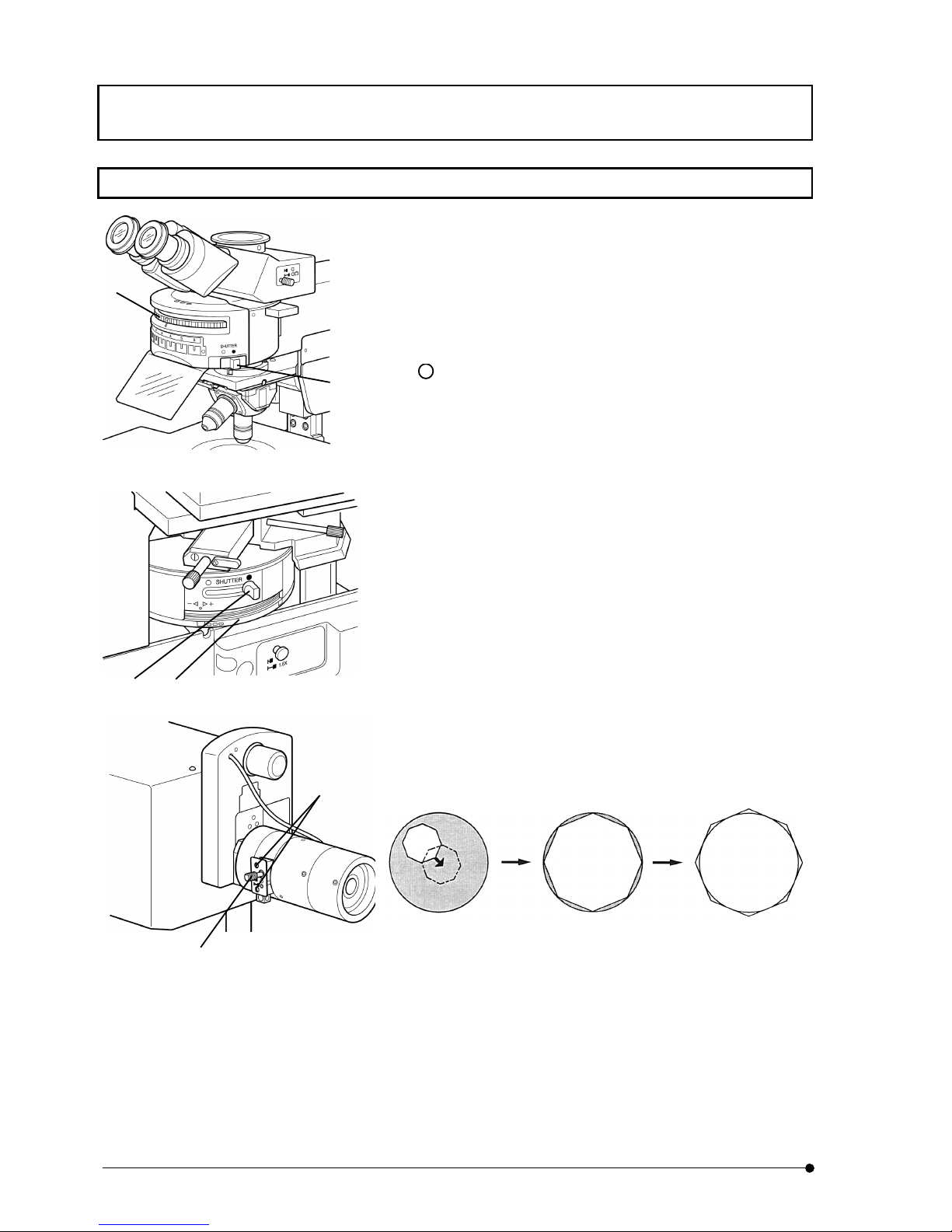
3-12 Adjustment of field iris diaphragm
1. Turn front side turret (1) and insert fluorescent mirror unit desired
into light path.
2. Turn rear side turret and insert reference mirror of No. 1 into light
path.
3. Set objective lens of 10x and set the specimen.
4. Move shutter knob (2) located at lower right side of turret to left
(
mark side) to open the shutter.
5. Use coarse/fine handle or, in case of motorized microscope, use
focus handle unit or focusing button on microscope frame to
bring the specimen in focus.
6. Pull out field iris diaphragm lever (3) located at side of
illumination tube and squeeze it to the smallest diameter.
7. Insert the Allen screwdriver that comes as accessory into
centering hole (4) of microscope frame located at side of
illumination tube (2 places) and adjust the axis of field iris
diaphragm image in a way that it comes in the same axis with the
filed of view.
8. Push in field iris diaphragm lever (3) and open field iris
diaphragm until it inscribes the field of view. In case that the axis
is out of center, do centering procedure again.
9. Push in field iris diaphragm lever (3) further and make the
aperture to circumscribe with field of view.
(In case of BX)
(In case of IX)
(1)
(1)
(2)
(3)
(4)
(2)
Page 37
DETAILS OF EACH OPERATION / Lamp centering
II .
DSU
II .
3-13
Page
3-13 Lamp centering
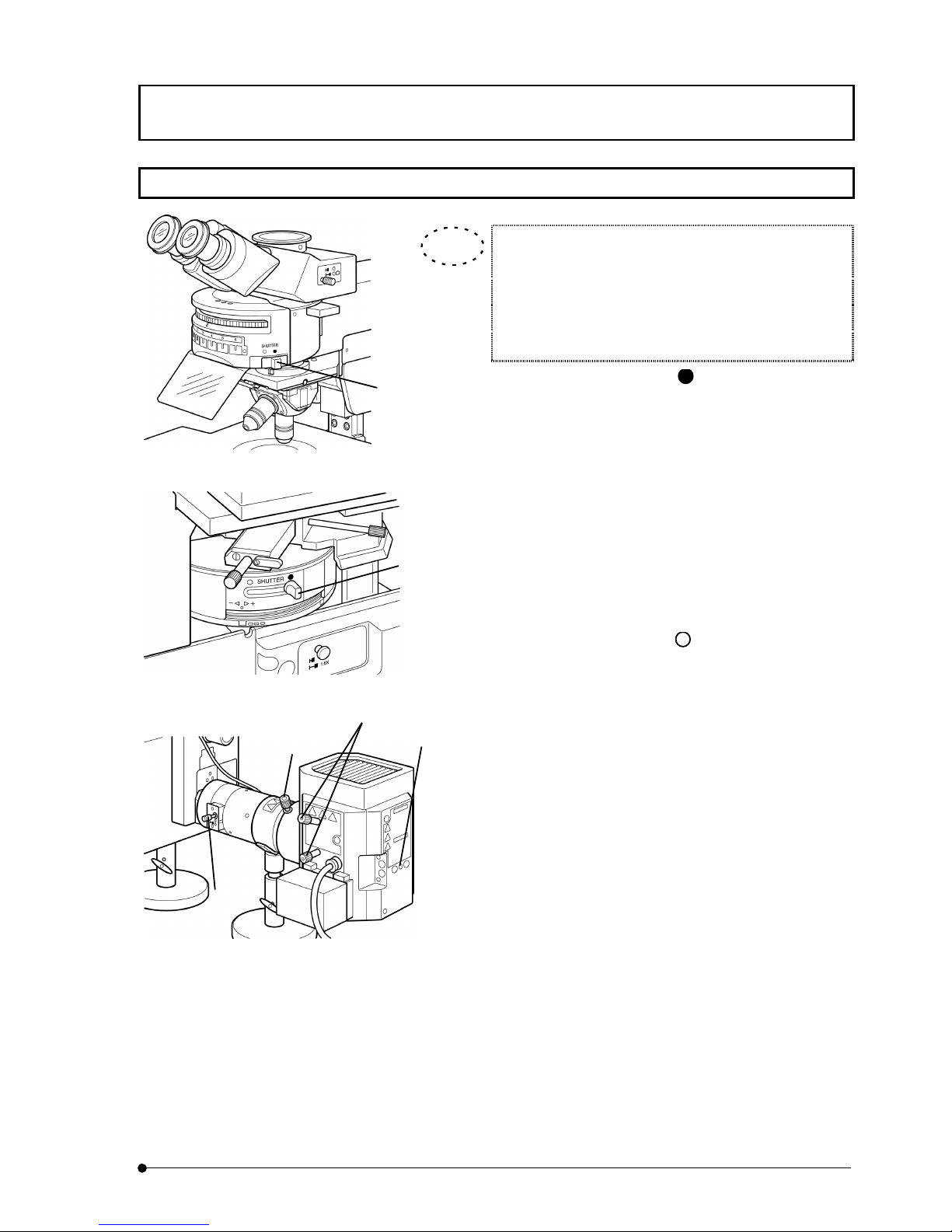
Lamp centering should be done after arc image of lamp is
stablized after main switch was turned ON (5 to 10
minitues later after lamp ON).
In case that frost filter 32FR80 is used, displace it from
light path.
1. Move shutter knob (1) to right ( mark side) to close the
shutter.
2. Turn front side turret and insert fluorescent mirror unit of B or
IB excitation for visual observation into light path.
(In case that these mirror units are not installed, use other
fluorescent mirror unit. However, in case of fluorescent
mirror unit of U excitation, it is essentially required to observe
through ultraviolet light cutting plate.)
3. Turn rear side turret and insert reference mirror of No.1 into
light path.
4. Move shutter knob (1) to left (
mark side) to open the
shutter.
5. Put objective lens 10x into light path. Put centering target U-
CST on the stage and align center of view with cross line of
U-CST.
6. Turn revolving nosepiece and bring a place where the
objective lens does not exist into light path (objective cap
should also be displaced).
7. Pull out field iris diaphragm lever (2) (to make the view
squeezed).
8. Turn collector lens focusing knob (3) to project arc image on
U-CST. (A)
In case that the image is not projected, turn lamp centering
knob (4).
9. Turn lamp centering knob (4) and move arc image to center of
right (or left) half view. (B)
10. Insert the Allen screwdriver into mirror focusing screw (5)
located at back panel of lamp house and turns it to bring
mirror arc image in focus. (C)
(In case of BX)
(In case of IX)
TIP
(1)
(1)
(2)
(3)
(4)
(5)
Page 38
DETAILS OF EACH OPERATION / Lamp centering
II .
DSU
II .
3-14
Page
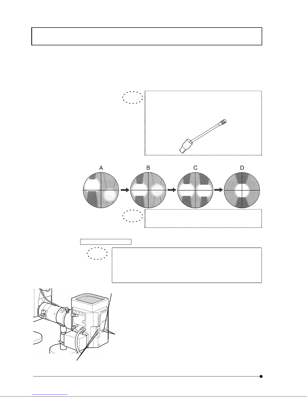
11. Turn lamp centering knob (4) and overlap arc image and
mirror arc image. (D)
When you feel that the collector lens focusing knob (3) is
hard to turn as it is located far away, insert extention
handle U-CLA (available at option) into the knob.
Lamp centering is not required until next lamp change.
Stringent mirror centering
Position of mirror is fixed after adjustment at ex-factory. When you wish
to make stringent adjustment further, excersize the following procedures
besides the procedures described in previous section. Meanwhile, note
that, after adjustment, the state at ex-factory cannot be revived.
1. Peel off blind seals (6) attached on back panel of lamp house,
using tweezers (2 places).
2. Loosen screws under the seals with use of the Allen
screwdriver. By loosening these two screws, the lock of
mirror would be released.
3. Next, peel off blind seals (7) (2 places) so that mirror
centering holes would appear.
4. Using the Allen screwdriver, adjust centering of mirror arc
image through these holes.
TIP
TIP
TIP
(6)
(7)
(5)
Page 39
DETAILS OF EACH OPERATION / Camera focus alignment
II .
DSU
II .
3-15
Page
3-14 Camera focus alignment
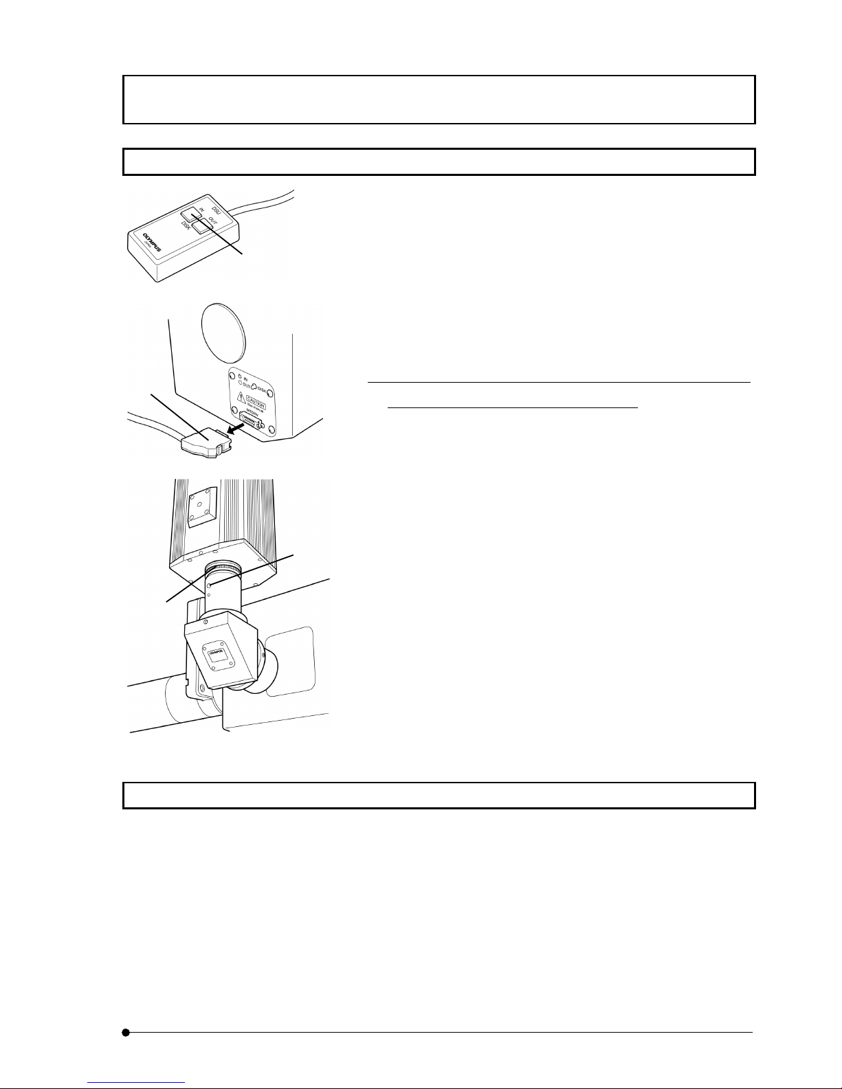
1. Bring a live image on monitor. Put objective lens 10x into light path
and displace the specimen from light path.
2. Press left IN button (1) of DSU hand switch and put the disk into light
path.
3. Stop the disk turning.
1) Switch off power of control box.
2) Pull out disk control cable (2) from disk box.
3) Switch on power of control box.
*
Upon completion of camera focus alignment, reverse the
procedures to go back to the original state.
4. Turn rear side turret and bring arbitrarily selected fluorescent mirror
unit or empty place into light path.
5. Turn front side turret and bring reference mirror of No.1 into light path.
6. Adjust transmitting light for enabling to see the strips of disk on
monitor.
7. Loosen fixing screw (3) located, using the Allen screwdriver.
8. Seeing live image on monitor, turn adjusting ring of mount adapter (4)
and bring strips of disk in focus.
9. Tighten the fixing screw (3) (at least one place) located at port, using
the Allen screwdriver.
3-15 Power shutdown
1. Switch off the lamp.
2. Switch off the control box.
3. Switch off the CCD camera.
(1)
(3)
(2)
(4)
Page 40

Page 41
VARIETIES OF OBSERVATION METHODS / Visual observation (BX)
II .
DSU
II .
4-1
Page
4 VARIETIES OF OBSERVATION
METHODS
4-1 Visual observation (BX)
This system can be used for not only reflected-light fluorescent observation but also it combines
transmitting bright-field observation, transmitted light phase contrast observation and transmitting
differential interference observation. Particularly, for specimen that color deterioration occurs earlier,
the color deterioration can be minimized by initial positioning through phase contrast observation or
differential interference observation. In addition, simultaneous observation of reflected-light
fluorescent combined with phase contrast observation or reflected-light fluorescent combined with
differential interference observation is possible, and it enables to observe which part of cell is emitting
fluorescence plainly.
4-1-1 Simultaneous observation of reflected-light fluorescent and phase
contrast
For phase contrast observation, condenser (U-PCD2) or universal condenser (U-UCD8)
dedicated for phase contrast and objective lens dedicated for phase contrast are
required.
1. Put dummy mirror unit (the place where fluorescent mirror unit is not installed) into
light path.
2. Set Ph indication equivalent to Ph indication of objective lens on phase contrast
turret.
3. Do centering between ring slit and phase plate.
4. Put mirror unit to observe excitation desired into light path and open shutter.
5. Adjust transmitting light intensity to get optimum brightness balance for fluorescent
and phase contrast and then, do the observation.
To adjust transmitting light intensity, use ND filter or brightness adjusting
button on microscope frame.
Regarding details of phase contrast observation, see instruction manual
of condenser for phase contrast or universal condenser.
TIP
TIP
TIP
Page 42
VARIETIES OF OBSERVATION METHODS / Visual observation (BX)
II .
DSU
II .
4-2
Page
4-1-2 Simultaneous observation of reflected-light fluorescent and transmitting
Nomarski differential interference
Transmitting Nomarski differential interference observation requires the following units.
(1) Universal condenser (U-UCD8)
(2) Transmitting DIC slider (U-DICT, U-DICTS, U-DICTHR or U-DICTHC)
(3) Analyzer (U-AN or U-AN360-3)
(4) Revolving nosepiece or motorized revolving nosepiece for DIC.
The analyzer (U-AN or U-AN360-3) for simultaneous observation is put in
upper insertion port above the dichroic mirror in order to use reflected-
light fluorescene effectively.
If analyzer (U-ANT) is put in transmitting DIC slider, the fluorescent image
may get dark and, also the analyzer may be burnt.
1. Put dummy mirror unit (the place where fluorescent mirror unit is not installed) into
light path.
2. Adjust polarizer of universal condenser and make it in Cross-Nicol state.
3. Insert revolving nosepiece into transmitting DIC slider.
4. Turn turret of universal condenser and select turret of Nomarski prism that meets
with objective lens to be used.
5. Put the objective lens to use into light path.
6. Set specimen on stage and bring it in focus.
7. Adjust field iris diaphragm of transmitting illumination system (built-in the
microscope) and aperture of universal condenser.
8. Turn prism knob of transmitting DIC slider and adjust contrast of differential
interference image.
9. Put mirror unit to observe excitation desired into light path and open shutter.
10. Adjust transmitting light intensity so as to get optimum brightness for fluorescent
and differential interference image.
Regarding details of transmitting differential interference observation, see
manual of Universal condenser (U-UCD8).
TIP
TIP
Page 43
VARIETIES OF OBSERVATION METHODS / Visual observation (BX)
II .
DSU
II .
4-3
Page
When change of reflected-light fluorescence and transmitting Nomarski
differential interference is frequently done and simultaneous observation
is also required, it is recommended that high abrasion-resistant analyzer
slider (U-ANH) is used instead of analyzer (U-AN).
When change of reflected-light fluorescence and transmitting Nomarski
differential interference is frequently done but simultaneous observation
is not required, it would be convenient if mirror unit (U-MDICT3) for
differential interference is attached at front side turret, instead of using
analyzer (U-AN or U-ANH).
If the fluorescent mirror unit is changed to differential interference mirror
unit, the analyzer comes into light path together so that the changeover is
easy.
TIP
Page 44
VARIETIES OF OBSERVATION METHODS / Visual observation (IX)
II .
DSU
II .
4-4
Page
4-2 Visual observation (IX)
This system can be used for not only reflected-light fluorescent observation but also it combines
transmitting bright-field observation, transmitted light phase contrast observation and transmitting
differential interference observation. Particularly, for specimen that color deterioration occurs earlier,
the color deterioration can be minimized by initial positioning through phase contrast observation or
differential interference observation. In addition, simultaneous observation of reflected-light
fluorescent combined with phase contrast observation or reflected-light fluorescent combined with
differential interference observation is possible, and it enables to observe which part of cell is emitting
fluorescence plainly.
IX81 or IX71 provides lamp ON-OFF button. Use these buttons when you change to fluorescent
observation only.
4-2-1 Simultaneous observation of reflected-light fluorescence and phase
contrast
For phase contrast observation, any one of condenser IX2-LWUCDA, IX2-
LWUCD, IX-ULWCD or U-UCD8 and objective lens for phase contrast are
required.
1. Put dummy mirror unit (the place where fluorescent mirror unit is not installed) into
light path.
2. Set Ph indication equivalent to Ph indication of objective lens on phase contrast
turret.
3. Do centering between ring slit and phase plate.
4. Put mirror unit to observe excitation desired into light path and open shutter.
5. Adjust transmitting light intensity to get optimum brightness balance for fluorescent
and phase contrast and then, do the observation.
To adjust transmitting light intensity, use ND filter or green filter.
Alternatively, adjust brightness at microscope side.
Moreover, be careful that, if halogen lamp were used at low voltage
applied at lamp off time, the lamp is susceptible to shorten its life.
TIP
TIP
TIP
TIPTIP
Page 45
VARIETIES OF OBSERVATION METHODS / Visual observation (IX)
II .
DSU
II .
4-5
Page
4-2-2 Simultaneous observation of reflected-light fluorescence and differential
interference (transmitting)
Differential interference observation requires the following units.
(1) One of condenser, IX2-LWUCDA, IX2-LWUCD or U-UCD8.
(2) One of differential interference slider, U-DICT, U-DICTS, U-DICTHC or U-DICTHR
(3) Analyzer, U-ANT or IX2-AN
The analyzer IX2-AN for simultaneous observation is put in lower
insertion port below the dichroic mirror in order to use reflected-light
fluorescene effectively.
If analyzer (U-ANT) is put in diffrential interference slider, the fluorescent
image may get dark and, also the analyzer may be burnt.
1. Put dummy mirror unit (the place where fluorescent mirror unit is not installed) into
light path.
2. Adjust polarizer of universal condenser and make it in Cross-Nicol state.
3. Insert revolving nosepiece into differential interference slider.
4. Turn turret of condenser and select turret of Nomarski prism that meets with
objective lens to be used.
5. Put the objective lens to use into light path.
6. Set specimen on stage and bring it in focus.
7. Adjust field iris diaphragm and aperture of condenser.
8. Turn prism knob of differential interference slider and adjust contrast of differential
interference image.
9. Put mirror unit to observe excitation desired into light path and open shutter.
10. Adjust transmitting light intensity so as to get optimum brightness for fluorescent
and differential interference image.
When change of reflected-light fluorescence and transmitting Nomarski
differential interference is frequently done but simultaneous observation
is not required, it would be convenient if mirror unit (IX2-MDICT) for
differential interference is attached at front side turret, instead of using
analyzer (IX2-AN). If the fluorescent mirror unit is changed to differential
interference mirror unit, the analyzer comes into light path together so that
the changeover is easy.
TIP
TIPTIP
Page 46
VARIETIES OF OBSERVATION METHODS / Camera observation (BX-IX)
II .
DSU
II .
4-6
Page
4-3 Camera observation (BX-IX)
This system provides reflected-light fluorescent observation and also, by changeover of rear side
turret, it enables camera observation for transmitting bright-field observation, transmitted light phase
contrast observation and transmitting differential inteference observation.
4-3-1 Transmitting bright-field and transmitted light phase contrast observation
To execute camera observation for each transmitting, the system should be arranged for
visual observation as described in previous section, 4-1 and 4-2.
1. Upon setting for visual observation, put dummy mirror unit of rear side turret (the
place where fluorescent mirror unit or reference mirror is not installed) into light
path.
2. Turn front side turret and put reference mirror of No.1 into light path.
3. If necessary, adjust transmitting light intensity and then, enter camera setting.
4-3-2 Transmitting differential interference observation
To execute differential interference camera observation, attach IX2-MDICT to rear side
turret in case of BX or U-MDICT3 in case of IX.
Arrange the system for visual observation as described in previous section, 4-1 and 4-2.
1. Upon setting for visual observation, put IX2-MDICT of rear side turret into light path
in case of BX or U-MDICT3 in case of IX.
2. Turn front side turret and put reference mirror of No.1 into light path.
3. If necessary, adjust transmitting light intensity and the, enter camera setting.
TIP
Page 47
TROUBLESHOOTING GUIDE
II .
DSU
II .
5-1
Page
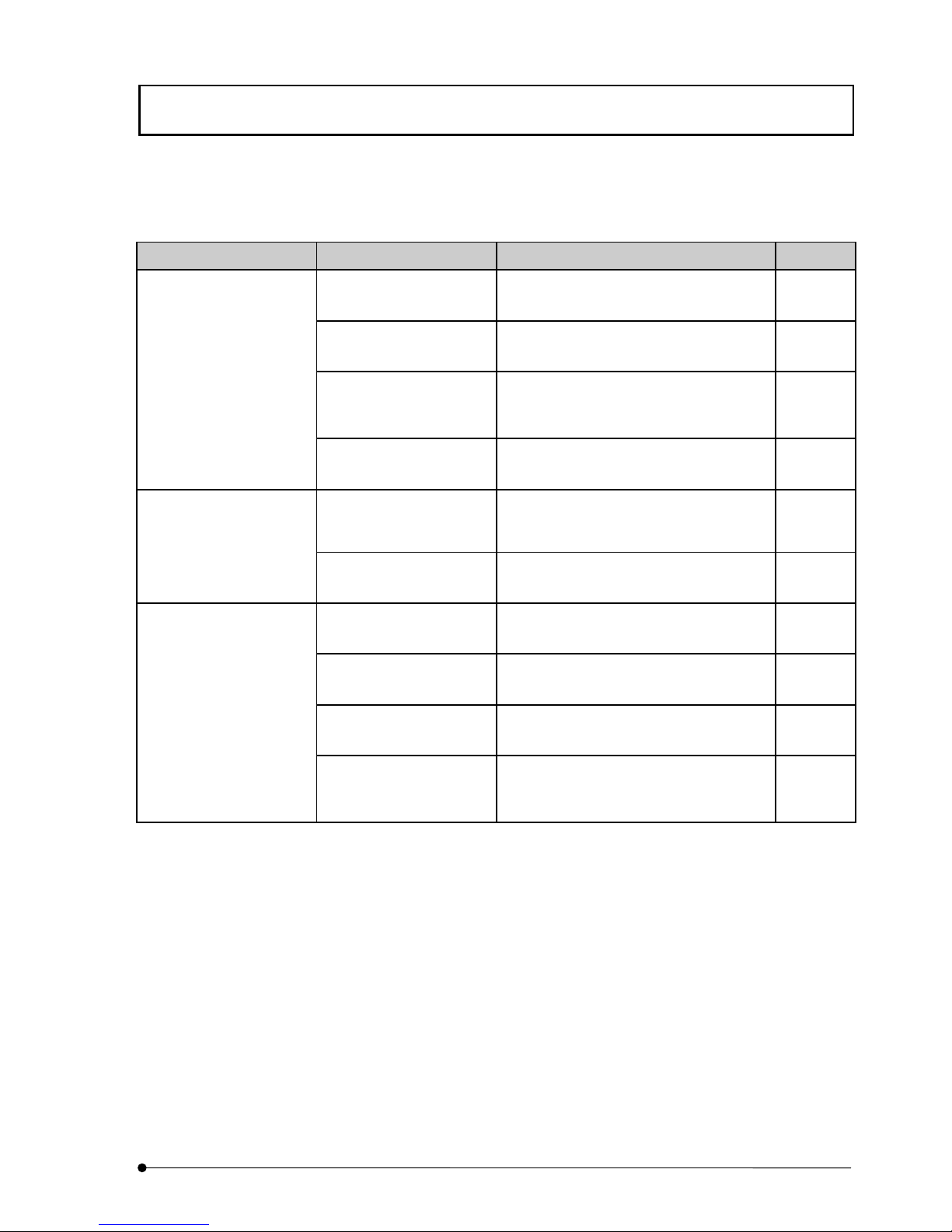
5 TROUBLESHOOTING GUIDE
Depending upon how the system is used, it may not exhibit adequate performance of the system, though it may
not be a failure. When trouble occurs, exercise adequate countermeasure with reference to the following table.
In case that trouble has not been improved, please contact local Olympus representative for assistance.
Trouble Cause Countermeasure Ref.
Cable is not connected
correctly.
Connect cable correctly. 8-1
Disk unit is not correctly
inserted into disk box.
Insert disk unit into correct position firmly. 8-13
Interlock function is
activated as access panel
is not closed correctly.
Attach access panel firmly. 8-13
Disk does not turn.
• Stripes of disk appear on
the monitor.
• Confocal effect cannot
be acquired even if disk
were put into light path.
Transport lock is left as
attached.
Remove transport lock. 8-4
Mirror unit is about to
come off the cassette.
Remove turret from mirror unit cassette and
fix it to correct position firmly.
8-12Camera mirror unit does
not turn.
Electric filter wheel does
not turn.
Cable is not connected
correctly.
Connect cable correctly. 8-1
Power of camera is not
turned ON.
Switch on power of camera. 3-5
Shutter is entering light
path.
Displace shutter from light path. 3-9
Filter like that is entering
light path.
Displace unnecessary substance from light
path.
3-11
Specimen image does not
appear on the monitor.
Combination of visual
mirror unit and camera
mirror unit is incorrect.
Set visual mirror unit (front side) to
reference mirror and set camera mirror unit
(rear side) to mirror unit.
3-10
3-7
Page 48
TROUBLESHOOTING GUIDE
II .
DSU
II .
5-2
Page
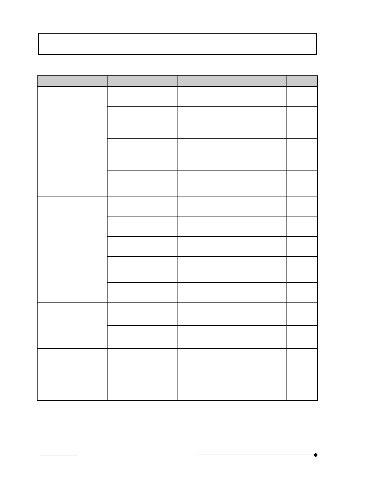
Trouble Cause Countermeasure Ref
Filter like that is entering
light path.
Displace unnecessary substance from light
path.
3-11
Exposure time of camera
is not correct.
Adjust to adequate time. Instruction
manual of
camera
used
Range of camera
brightness level is not
correct.
Adjust to adequate level. Instruction
manual of
camera
used
Confocal image is
extremely dark.
Combination of visual
mirror unit and camera
mirror unit is incorrect.
Put mirror unit that meets with purpose into
light path.
3-7
3-10
Centering of field iris
diaphragm is not done.
Do centering of field iris diaphragm
correctly.
3-12
Field iris diaphragm is
squeezed excessively.
Open aperture adequately. 3-12
Centering of lamp house is
not done.
Do centering of lamp house correctly. 3-13
Visual mirror unit is
positioned half way at
changeover.
Put mirror unit in click position firmly in
accordance with your purpose.
3-7
Field of view is obscured
or not evenly illuminated.
Shutter is positioned half
way.
Open shutter firmly. 3-9
Mirror unit is blurred. Clean adequately.
Cleanup and
Storage of
Introduction
Dust or dirt is visible in
filed of view.
Disk is dirty. Clean adequately.
Cleanup and
Storage of
Introduction
Exposure time of camera
is set to less than 200ms.
Set exposure time of camera to more than
200ms.
Instruction
manual of
camera
used
Confocal image is blinking.
Vibration at installation is
great.
Consult with our sales office. –
Page 49
TROUBLESHOOTING GUIDE
II .
DSU
II .
5-3
Page
Trouble Cause Countermeasures Ref.
Ambient light (such as
fluorescent lamp) is
entering light path.
Turn off fluorescent lamp or cut ambient
light with use of specimen cover.
–
Exposure time of camera
is not correct.
Adjust to adequate time. Instruction
manual of
camera
used
Range of camera
brightness level is not
correct.
Adjust to adequate level. Instruction
manual of
camera
used
Non-fluorescent glass is
not used.
Use non-fluorescent glass. –
Flare is remarkable.
Thickness of cover glass is
not suitable.
Use cover glass of 0.17mm thick. –
Camera focus is not
correct.
Adjust camera focus. 3-14Image is not clear.
Correct disk is not used for
objective lens.
Use suitable disk. 8-13
3-3
Page 50

Page 51
SPECTRAL CHARACTERISTICS OF FILTERS
II .
DSU
II .
6-1
Page
6 SPECTRAL CHARACTERISTICS OF
FILTERS
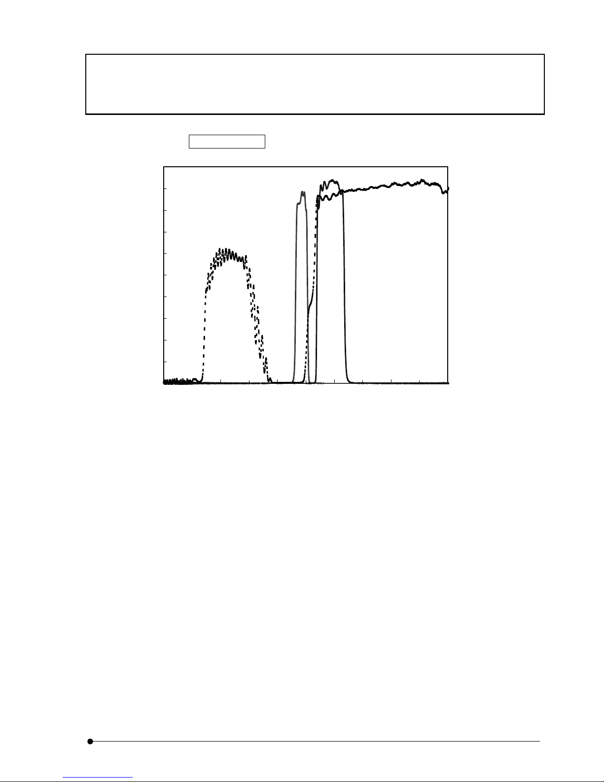
RFPHQ DSU-MRFPHQ
0%
100%
300 400 500 600 700 800
Wavelength (nm)
Transmittance (%)
DM560
BA570-620HQ
BP535-555
Page 52

Page 53
SPECIFICATIONS / BX Series
II .
DSU
II .
7-1
Page
7 SPECIFICATIONS
7-1 BX Series
Item Specifications
Lens barrel magnification 1x
Number of views Visual observation side: FN22mm (In reflected illumination, peripheral
light intensity may be insufficient if objective lens power is of 20x or less)
Camera obervation side: FN11mm
Shutter Knob at front side turret cover.
Turret coupling system
Field iris diaphragm Field iris diaphragm built-in type (with centering function)
Aperture opening: Knob push-pull method
Centering: With use of the Allen screwdriver
Slider slot AN slot: 32X7.5mm through hole, with click (dummy when not used)
PO slot: 32X7.5mm through hole, with click (dummy when not used)
Disk Belt-drive system supported by spindle
DC motor
Electrically driven IN/OUT system (with hand switch)
Filter Electric filter wheel
Electric 6-hole turret system 1: Empty hole
2: ND25
3: ND12
4: ND6
5: ND3
6: ND1.5
Front turret Manual 6-hole turret system
1-hole fixed mirror accessory (DM680)
Mirror unit turret
Rear turret Electric 6-hole turret system
1-hole fixed mirror accessory (Reference mirror)
Stand Height adjustable
2 units provided.
Observation methods Camera observation
1) Incident-light fluorescent disk confocal
2) Incident-light fluorescent
3) Transmitting
Visual observation
1) Incident-light fluorescent
2) Incident-light fluorescent + Transmitting differential interference
3) Incident-light fluorescent + phase contrast
4) Transmitting
Dimensions of main unit
567mm(W)×386mm(D) ×221mm(H)
Weight 12.5kg
This device complies with the requirements of both directive 89/336/EEC concerning electromagnetic
compatibility and directive 73/23/EEC concerning low voltage. The CE marking indicates compliance with
the above directives.
Page 54
SPECIFICATIONS / IX Series
II .
DSU
II .
7-2
Page
7-2 IX Series
Item Specifications
Lens-barrel magnification 1x
Number of views Visual observation side: FN22mm (In reflected illumination, peripheral
light intensity may be insufficient if objection lens is of 20x or less)
Camera observation side: FN11mm
Shutter Knob at front side turret cover.
Field iris diaphragm Field iris diaphragm built-in type (with centering function)
Aperture opening: Knob push-pull method
Centering: With use of the Allen screwdriver
Disk Belt-drive system supported by spindle
DC motor
Electrically driven IN/OUT system (with hand switch)
Filter Electric filter wheel
Electric 6-hole turret system 1: Empty hole
2: ND25
3: ND12
4: ND6
5: ND3
6: ND1.5
Front turret Manual 6-hole turret system
1-hole fixed mirror accessory (Reference mirror)
Mirror unit turret
Rear turret Electric 6-hole turret system
1-hole fixed mirror accessory (Reference mirror)
Stand Height adjustable
2 units provided.
Observation methods Camera observation
1) Incident-light fluorescent disk confocal
2) Incident-light fluorescent
3) Transmitting
Visual observation
1) Incident-light fluorescent
2) Incident-light fluorescent + Transmitting differential interference
3) Incident-light fluorescent + phase contrast
4) Transmitting
Dimensions of main unit
408mm(W)×386mm(D) ×221mm(H)
Weight 10kg
This device complies with the requirements of both directive 89/336/EEC concerning electromagnetic
compatibility and directive 73/23/EEC concerning low voltage. The CE marking indicates compliance with
the above directives.
Page 55
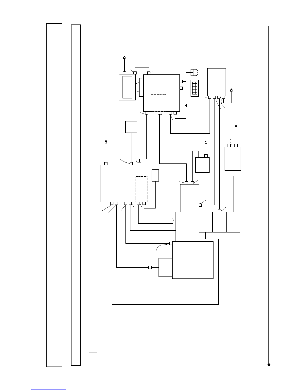
ASSEMBLY / System block diagram
II .
DSU
II .
8-1
Page
8 ASSEMBLY
8-1 System block diagram
8-1-1 In case of BX
Microscope
BX51/
BX52/
BX61/
BX62/
BX51WI/
BX61WI
Moto rize d
Filter Wheel
U-FW R
DSU Disk Box
DU-DBIX
Mercury
lamp or
Xenon lamp
Halogen
Lamp
U-LH100-3
(High speed
Filter Wheel
& Shutter)
Round type
Connector
Lamp power
cable 2m
(High speed
Filter Wheel
& Shutter
Controller)
Disk Control Cable 2m
(High
speed
Filter
Wheel)
(Camer
a unit)
Round type
5-pin
Controller Power
cable 2m
Control Box
IX2-UCB
DSU Motor
Drive Board
DU-MTDRV
50-pin half
pitch
(Computer)
Computer power
cable 2m
Microscope Communication
cable 2m
(Camera
Power
Supply)
Camera power
cable 2m
D-SUB 15 pin
Camera power cable 3m
D-SUB 15 pin
Control cable 1.7m
Control cable 1.7m
20-pin Half pitch
Halogen lamp extension cable 1.7m
Microscope control cable 2m
Turret cable 2m
D-SUB 9 pin
20-pin Half pitch
Camera signal cable 4.5m
D-SUB 25-pin
Parallel port
Serial port
Round type
4-pin
Round type 4-pin
(1 side)
Round type 8-pin
(FW3)
Round type 8-pin
(RFACA/F1)
Filter wheel cable 2m
50-pin half pitch
(MAIN2)
20-pin
Half pitch
Merc ury l amp
power supply or
Xenon lamp
power supply
Lamp cable 2m
D-SUB 15-pin (A side)
D-SUB 15-pin (B side)
(Camera
signal
processin
g board)
Controller
Communica
tion Cable
1.8m
20-pin Half pitch
Halogen lamp cable 0.3m
Mous e
Display
cable
2m
Display Output
connector
Display Input
connector
DSU Hand Switch
DU-HSW
DSU Hand Switch
Cable 2m
20-pin Half pitch
Hand Switch Cable 2m
Hand Switch
U-HSTR2
Control box Power
Cable 2m
Display P ower
cable 2m
Keyboard
(Monitor)
Page 56
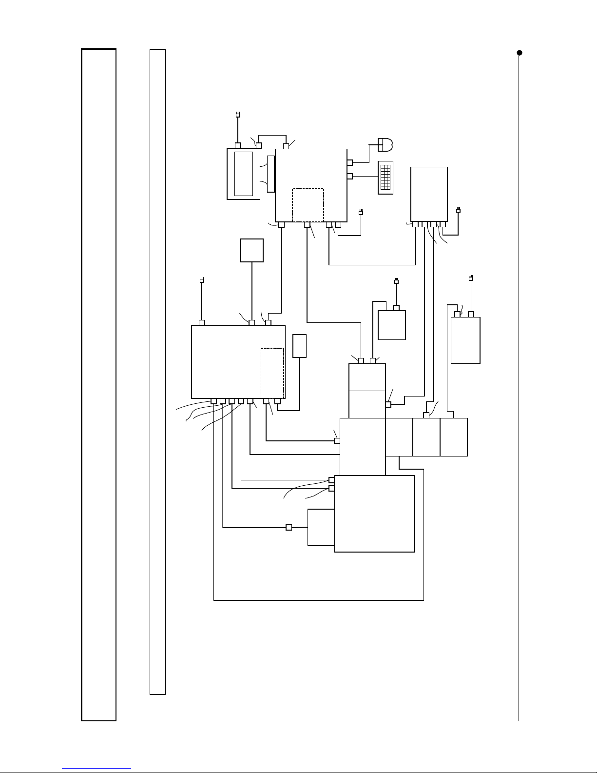
ASSEMBLY / System block diagram
II .
DSU
II .
8-2
Page
8-1-2 In case of IX
Motorized
Filter Wheel
U-FWR
DSU Disk Box
DU-DBIX
Mercury
lamp or
Xenon lamp
Halogen
Lamp
U-LH100-3
(High speed
Filter Wheel
& Shutter)
Round type
Connector
Lamp power
cable 2m
(High speed
Filter Wheel
& Shutter
Controller)
Disk Control Cable 2m
(High
speed
Filter
Wheel)
(Camer
a unit)
Round
type
5-pin
Controller Power
cable 2m
Control Box
IX2-UCB
DSU Motor
Drive Board
DU-MTDRV
50-pin
half pitch
36-pin
half pitch
(Computer)
Computer power
cable 2m
Microscope Communication
cable 2m
(Camera
Power
Supply)
Camera power
cable 2m
D-SUB 15 pin
Camera power cable 3m
D-SUB 15 pin
Control cable 1.7m
Control cable 1.7m
20-pin Half pitch
Halogen lamp extension cable 1.7m
Microscope control cable 2.2m
Turret cable 2m
D-SUB 9 pin
20-pin Half
pitch
Camera signal cable 4.5m
D-SUB 25-pin
Parallel port
Serial port
Round type
4-pin
Round type 4-pin (1 side)
Microscope control cable 1.2m
Round type 8-pin (FW3)
Round type 8-pin
(RFACA/F1)
Filter wheel cable 2m
50-pin half pitch (MAIN2)
36-pin half pitch (MAIN3)
20-pin
Half pitch
Merc ury l amp
power supply or
Xenon lamp
power supply
Lamp cable 2m
D-SUB 15-pin (A side)
D-SUB 15-pin (B side)
(Camera
signal
processin
g board)
Controller
Communication
Cable 1.8m
20-pin Half pitch
Halogen lamp cable 0.3m
Display
cable 2m
Display Output
connector
Display Input
connector
DSU Hand Switch
DU-HSW
DSU Hand Switch
Cable 2m
20-pin Half pitch
Hand Switch Cable 2m
Hand Switch
U-HSTR2
Control box Power
Cable 2m
Display P ower
cable 2m
Mouse
Keyboard
(Monitor)
Microscope
IX71/
IX81
Page 57
ASSEMBLY / Installation of light illuminator
II .
DSU
II .
8-3
Page
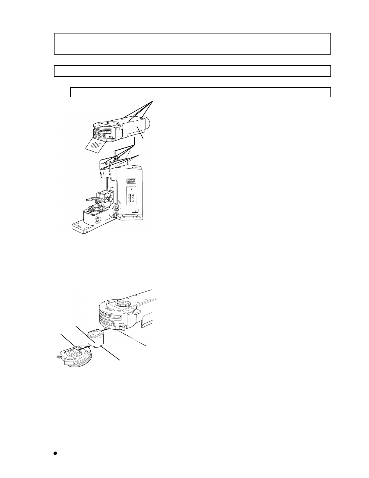
8-2 Installation of light illuminator
8-2-1 In case of BX
1. Remove caps of mounting screws (2) on top of light illuminator (1)
with use of tweezers.
2. When using BX61, BX62, BX51 or BX52, put arm lift kit (W I-
ARMAD) on the arm and fix mounting screws (3) (4 pieces) to the
light illuminator firmly, using dedicated
the Allen wrench that
comes with kit.
3. When mounting the light illuminator, put it over slightly forward
position without aligning mounting screws (2) with mounting holes
(4) of microscope body.
4. Next, pressing the light illuminator towards right side and press it
towards rear side so that it would be positioned in correct
mounting position.
5. While pressing the light illuminator towards rear side, fix mounting
screws (2) (4 pieces) to the light illuminator by turning the
dedicated
the Allen wrench that comes with kit in clockwise
direction.
6. Attach caps of mounting screws (2) to their original positions.
7. When using BX61, BX62, BX51 or BX52, revolving nosepiece
adapter (DSU-READ) must be attached as follows.
1)
Loosen fixing screw (5) of microscope frame with use of the
dedicated the Allen screwdriver.
2) Align revolving nosepiece adapter (6) with mount dovetail
from front side of microscope frame and push it and then,
tighten fixing screw (5).
3) Loosen fixing screw (7)
located at right side of revolving
nosepiece adapter, using the Allen screwdriver.
4) Align revolving nosepiece (8) with mount dovetail from front
side of microscope frame and push it and then, tighten fixing
screw (7).
(2)
(4)
(1)
(3)
(5)
(6)
(7)
(8)
Page 58
ASSEMBLY / Installation of disk box
II .
DSU
II .
8-4
Page
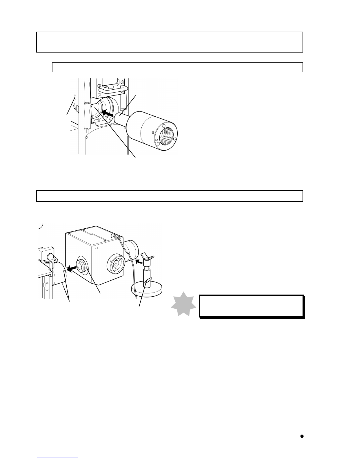
8-2-2 In case of IX
1. Loosen fixing screws (1) (2 places) that fix light
illuminator to microscope frame, using the Allen
wrench.
2. Insert light illuminator (2) into mounting hole (3).
Observe that pin at lower part of light illuminator
is aligned with mounting hole slot.
3. Tighten fixing screws (1) for light illuminator
and fix the light illuminator (2 places).
8-3 Installation of disk box
1. Loosen fixing screws (1) (2 places), using the Allen
screwdriver.
2. Insert disk box (2) into light illuminator, observing pin
position, and push it until it hits the dead end.
3. Tighten fixing screws (1) (2 places), using the Allen
screwdriver.
4. Loosen fixing screw (3) of stand that comes as
accessory and put the stand underneath the
observation tube of disk box.
Stand should be attached for sure to
prevent upside down.
5. Extend the stand to apply fixing place to observation
tube and tighten fixing screw (3).
Note
(1)
(both sides)
(3)
(2)
(2)
(3)
(1)
Page 59
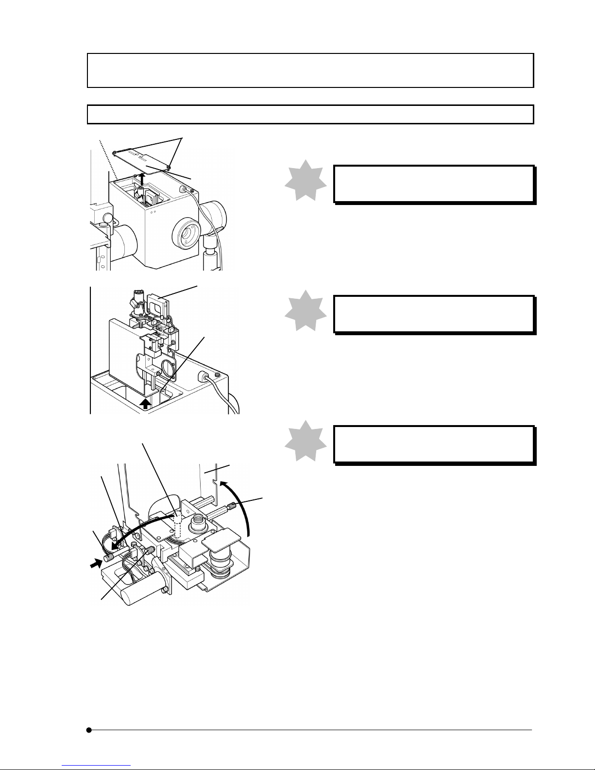
ASSEMBLY / Removal of transportation lock
II .
DSU
II .
8-5
Page
8-4 Removal of transportation lock
This work should be done before connecting
cable of disk box.
1. Loosen screws (2) (2 places) located on top of disk box to
fasten at front side of access panel to microscope frame and
detach the access panel (1).
2. Loosen fixing screw from hole (3) located at left side of disk
box and pull the disk unit (4) upward.
Pull up the disk unit carefully so as not to hit it
inside wall of disk box.
3. Loosen knobs (5) (2 places) of disk unit and open disk cover
(6).
4. Loosen transportation lock knob (7) and remove it from disk
unit (4). Attach the transportation lock knob you just removed
to threaded hole (8) of the disk unit.
Keep transportation lock knob with care as it
may be used for transportation again.
When you continue to install disk, see 8-13 Disk installation
and change.
5. Return disk cover (6) to original position and fix it by
tightening disk unit knobs (5) (2 places).
6. Align disk unit (4) with mount dovetail (9) of disk box and
push it from top to dead end.
7. Tighten fixing screw (3), using the Allen screwdriver.
8. Attach access panel (1) on top of disk box and tighten fixing
screws (2) (2 places).
Note
Note
Note
(1)
(2)
(3)
(5)
(7)
(6)
(7)
(5)
(8)
(9)
(4)
Page 60
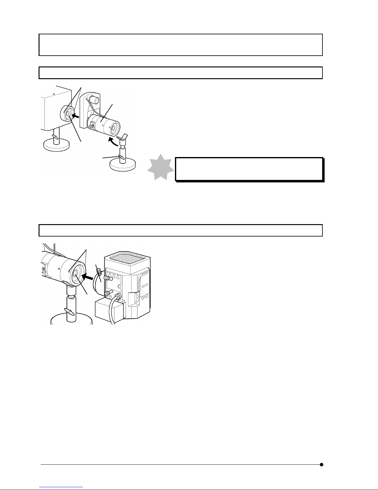
ASSEMBLY / Installation of illuminator
II .
DSU
II .
8-6
Page
8-5 Installation of illuminator
1. Loosen fixing screws (1) (2 places) that fix disk box to microscope
frame, using the Allen screwdriver.
2. Insert illuminator (2) into disk box (3) and push it to the dead end. At
this time, attach it in a way that FS unit faces towards observer.
3. Tighten fixing screws (1) (2 places), using the Allen screwdriver.
4. Loosen fixing screw (4) of stand and put stand that comes as
accessory underneath the illuminator.
Stand should be attached for sure to prevent upside
down.
5. Extend the stand to apply fixing place to illuminator and tighten fixing
screw (4).
8-6 Installation of lamp house
1. Loosen fixing screws of lamp house mount adapter (1) (2
places), using the Allen screwdriver.
2. Insert lamp house (2) into lamp house mount adapter of light
illuminator (3) and push it to the dead end.
3. Tighten fixing screws (1) (2 places), using the Allen
screwdriver.
Note
(4)
(2)
(3)
(1)
(2)
(3)
(1)
Page 61
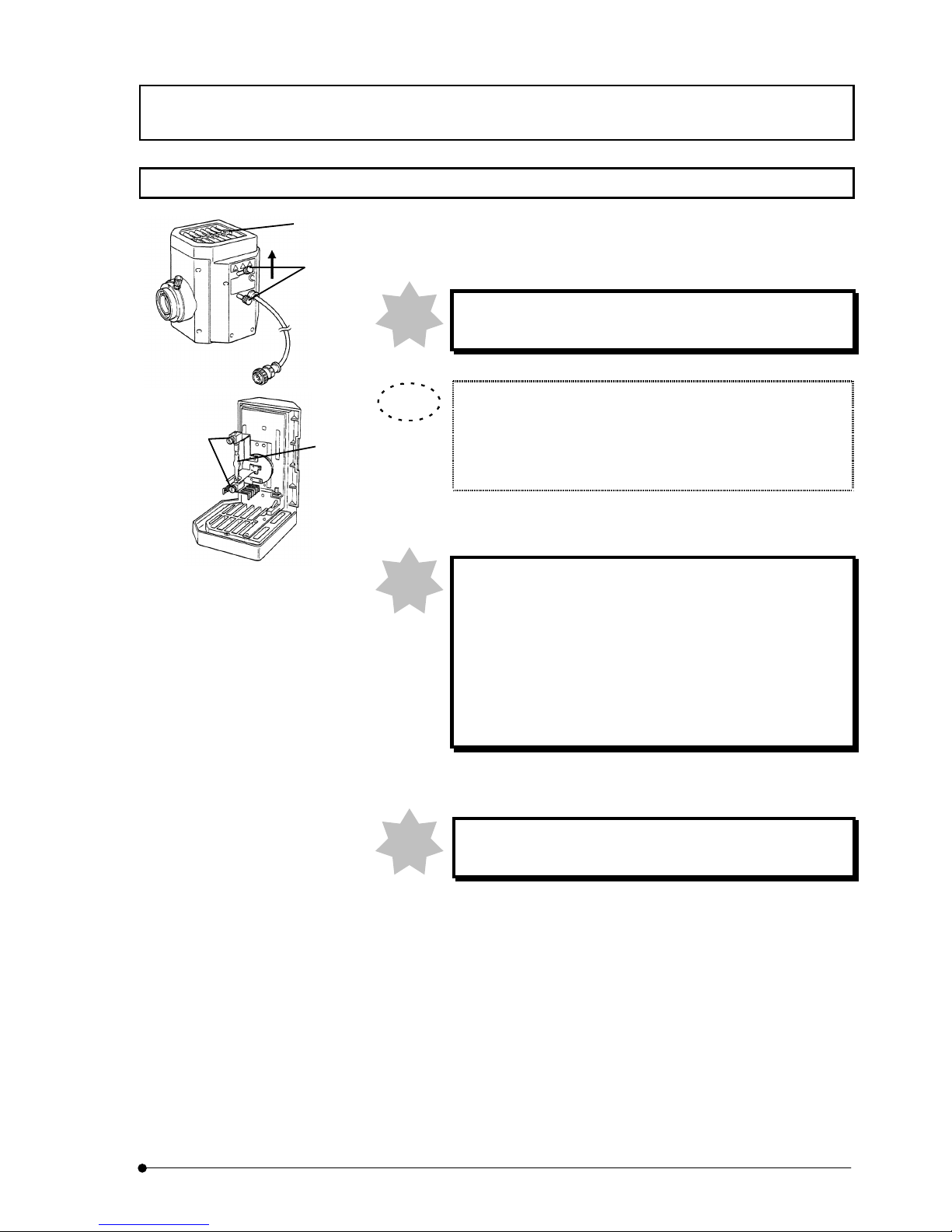
ASSEMBLY / Installation of mercury lamp
II .
DSU
II .
8-7
Page
8-7 Installation of mercury lamp
1. Loosen socket fixing screw (1), using the Allen screwdriver.
2. Hold upper part of lamp house and pull it vertically to detach socket
section.
If you hold centering knob (2), it may cause a failure.
3. Place socket section upside down as illustrated.
At ex-factory, a support is provided for transportation. When
changing lamp, old lamp is yet installed. When installing lamp
newly or changing lamp, loosen fixing screws (3) (2 places) that
hold the support or old lamp.
4. Install mercury lamp designated to mounting socket firmly, observing +
polarity to upper base and – polarity to lower base.
Lamp to use should be USH102D (made by Ushio Electric)
or HBO103W/2 (made by OSRAM).
Care must be taken so as not to attach finger mark or dirt
on lamp. If the surface of lamp is contaminated, it may burst
due to distotion of glass. If contaminated, use a cloth like
gauze dipped in mixture of alcohol (3): ether (7) and wipe
out the surface of lamp carefully.
5. Return socket section that the lamp is attached to original position and
tighten fixing screw (1).
Socket section must be lowered vertically, aligning lamp
house outer side and socket section outer side.
(1)
(2)
(3)
(4)
Note
TIP
Note
Note
Page 62
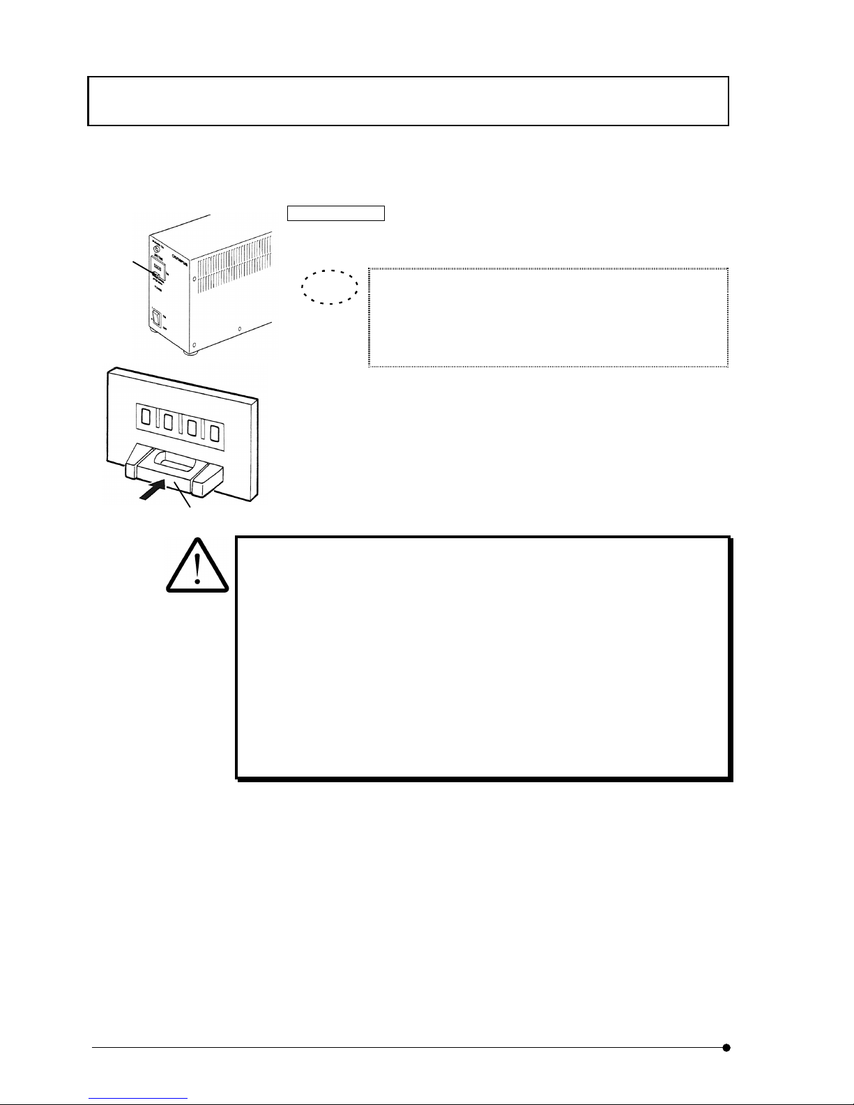
ASSEMBLY / Installation of mercury lamp
II .
DSU
II .
8-8
Page
Life meter setting
1. Reset button (1) is located at front panel. Press center part (2) of this
button and make the display to 000.0.
Display – 000.0 means time. Life of lamp – USH102D is 200
hours, while HBO103W/2 is 300 hours. When 200.0 is displayed
for USH102D, replace the lamp. Likewise, when 300.0 is
displayed for HBO103W/2, replace the lamp.
Change of mercury lamp
l
Life of mercury lamp is either 200 or 300 hours. Lamp may burst when the life
of lamp is over. When you used 200 hurs (USH102D) or 300 hours
(HBO103W/2), replace the lamp with new one for safety.
l
For safety purpose, wait about 10 minutes after power of lamp was turned off
and see if the lamp and lamp house have been duly cooled down. Then, verify
that main switch is turned OFF and, after output connector is detached from
lamp house, remove the lamp.
See 8-7 Installation of mercury lamp for method of change.
l
Upon completion of lamp change, set life meter to 000.00 as explained above.
(1)
(2)
TIP
Page 63
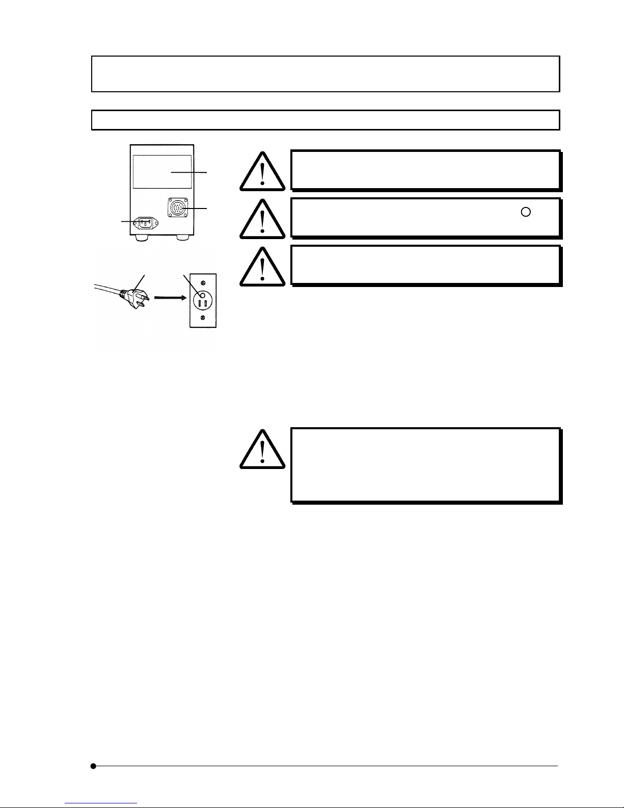
ASSEMBLY / Lamp power supply setting
II .
DSU
II .
8-9
Page
8-8 Lamp power supply setting
Cord or cable is weak against bend or twist. Care must be
taken so as not to apply excessive force.
When connecting power cord, turn main siwtch to mark
side (OFF).
Use power cord that comes our accessory for sure.
1. Verify that voltage and frequency of input power are within the range as
shown in identifying plate (1).
(The 100 V system can be used with voltages in the 100 to 120 V range
and 200 V system can be used with voltages in the 220 V to 240 V range,
both with frequencies of 50 or 60 Hz.)
2. Connect connecting cord to connector (2) of power supply unit.
3. Install power cord to input receptacle (3) of power supply unit and insert
power plug (4) into power consent (5).
Power cord should be connected to 3-core consent with
earth terminal. When the earth of consent is not connected,
the electric safety performance intended by our company
may not be acquired.
(1)
(2)
(3)
(4) (5)
Page 64
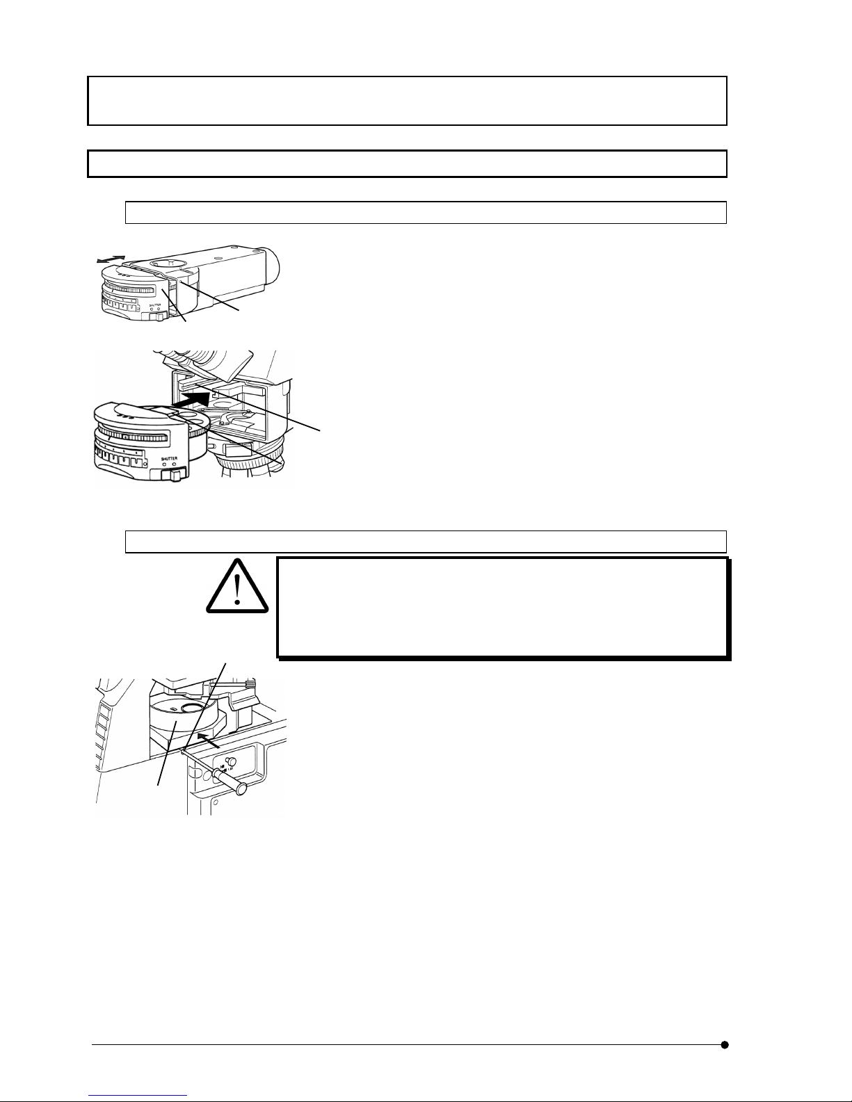
ASSEMBLY / Installation of front side turret
II .
DSU
II .
8-10
Page
8-9 Installation of front side turret
8-9-1 In case of BX
1. (Removal of turret). Loosen fixing screw (1) from hole (1) located at
right side of light illuminator and pull out turret (2) forward.
2. (Installation of turret). Align mount dovetail (3) of light illuminator and
mount dovetail (4) of turret and push the turret from front side gently
until it hits to the dead end.
3. Tighten fixing screw (1), using the Allen screwdriver.
8-9-2 In case of IX
When you remove cassette during operation, close option shutter for sure
or turn power of light source to OFF position.
If you remove mirror unit cassette while the shutter is open, it is dangerous
as the excited light would leak.
1. (Removal). Loosen fixing screw (1) of mount dovetail for cassette, using
dedicated the Allen screwdriver and push out the cassette (2) to arrow
direction.
2. (Installation). Align mount dovetail located at bottom of mirror unit
cassette and insert the cassette from left side and push it until it hits to
dead end.
3. Tighten fixing screw (1) of mount dovetail for cassette, using the Allen
screwdriver.
(1)
(2)
(1)
(2)
(3)
(4)
Page 65
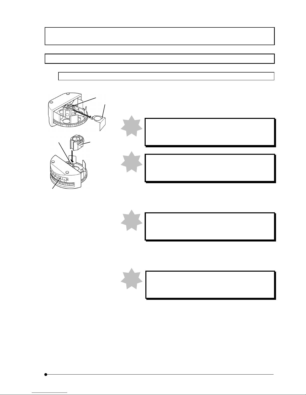
ASSEMBLY / Installation of visual mirror unit (front side)
II .
DSU
II .
8-11
Page
8-10 Installation of visual mirror unit (front side)
8-10-1 In case of BX
1. Turn turret upside down and loosen fixing screw (1), using dedicated the
Allen screwdriver and remove dummy mirror unit (2) (remove the dummy
mirror unit only where a mirror unit is to be installed from now on).
When mirror units already exist inside the cassette, be
careful so as not to touch dichroic mirror or excitation filter
with your finger.
Reference mirror of adjustment completed is attached at
No.1 position. Do not change the position of this reference
mirror.
2. Insert mirror unit (3) to be used into mount dovetail (4) of mirror unit and
push it until it hits to dead end and then, tighten fixing screw (1), using The
Allen screwdriver.
If the fixing screw (1) is loosened, it may interfere inside
turret cover and turret may not be able to turn. Tighten the
fixing screw even if mirror unit does not exist.
3. Verifying mount dovetail NO (4), insert identifying plate of mirror unit in
reverse way into the same number of display pocket (5) located at front of
turret.
In case that the identifying pocket for turret is used as
indicator for name of objective lens, it cannot be used as
indicator for mirror unit.
Note
Note
Note
Note
(1)
(3)
(4)
(5)
(2)
Page 66
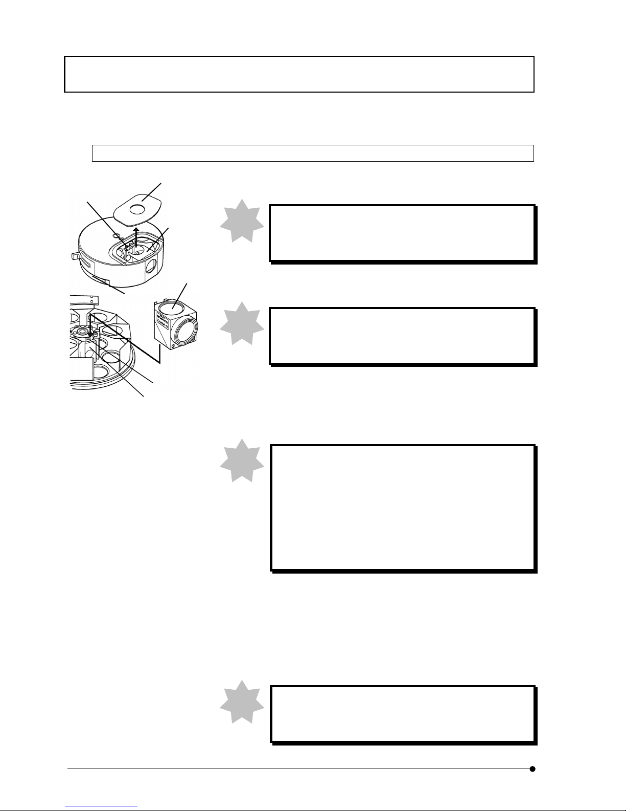
ASSEMBLY / Installation of visual mirror unit (front side)
II .
DSU
II .
8-12
Page
8-10-2 In case of IX
1. Remove cover (1) that is sucked with magnet from mirror unit cassette.
When mirror units already exist inside the cassette, be
careful so as not to touch dichroic mirror or excitation filter
with your finger.
2. Turn turret (2) of mirror unit cassette manually and align mirror unit
mounting position with mirror unit mounting hole.
Reference mirror of adjustment completed is attached at
No.1 position. Do not change the position of this reference
mirror.
3. Loosen fixing screw (3) of mirror unit mount dovetail for mirror unit cassette,
using dedicated the Allen screwdriver.
4. Displace dummy mirror unit (4) little by little circumferentially and pull it
towards outside of turret and detach it by pulling upward.
In case of reflected-light fluorescence observation, attach
dummy mirror unit for sure to the place where mirror unit is
not installed. In case of transmitting observation, dummy
mirror unit is not required. However, the fixing screw (3) for
mount dovetail should be tightened at the place where
dummy mirror unit is not installed. If this fixing screw is
loosened, head of screw may interfere when turret turns.
5. Insert mirror unit (5) into mirror unit mount dovetail (6) and push it until it
hits to dead end and then, tighten fixing screw (3), using dedicated the
Allen screwdriver.
6. Attach turret cover (1), aligning it with well of mirror unit cover.
7. Insert identifying plate for mirror unit, corresponding to number of turret
that comes into light path into display pocket of microscope frame.
When display pocket of microscope frame is used for
indicator of objective lens, it cannot be used as indicator of
mirror unit.
Note
Note
Note
(1)
(3)
(4)
(2)
(3)
(6)
(5)
Note
Page 67
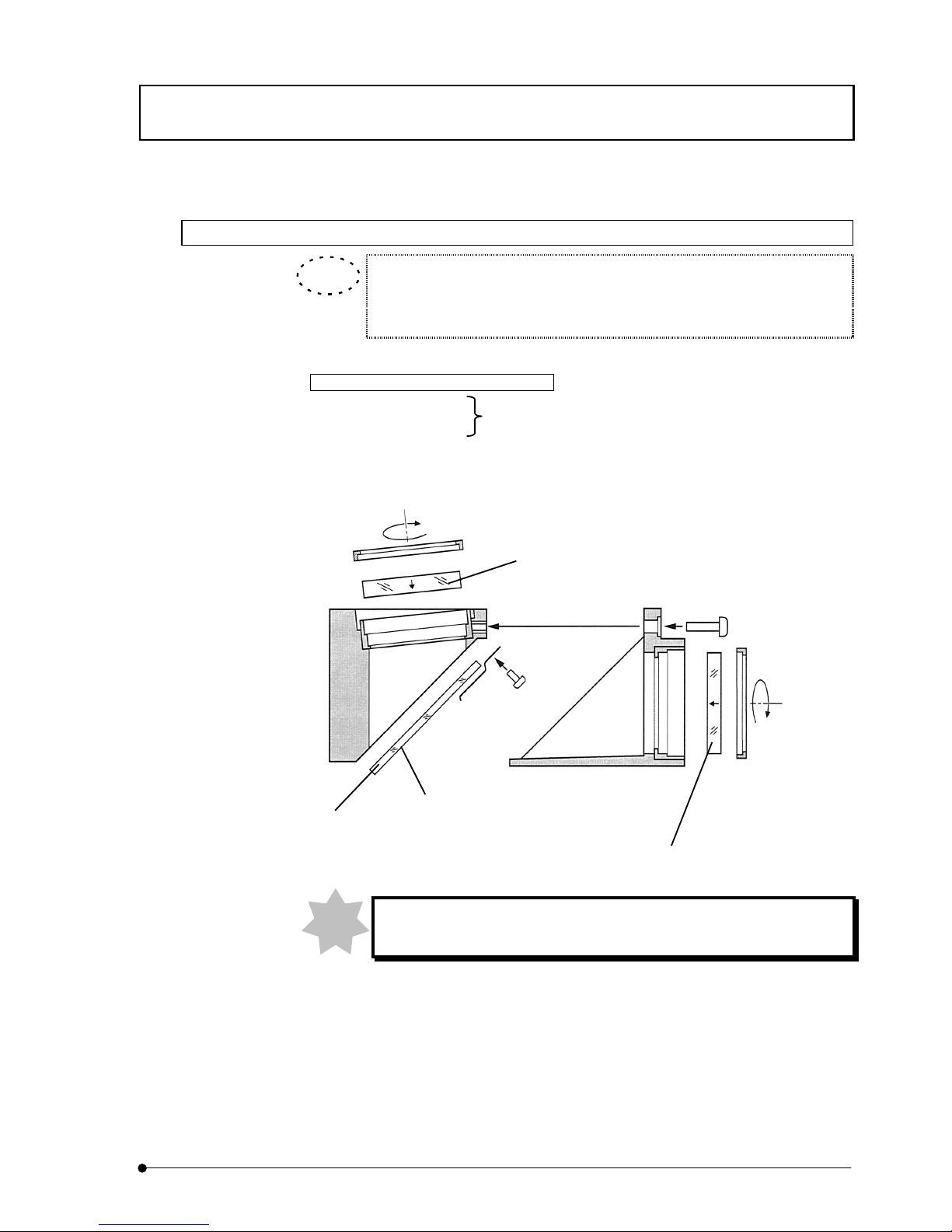
ASSEMBLY / Installation of visual mirror unit (front side)
II .
DSU
II .
8-13
Page
8-10-3 Method to make optionnal fluorescent mirror unit
You can make optional fluorescent mirror unit by attaching mirror unit frame
U-MF2 to commercially available barrier Filter, excitation filter or dichroic
mirror.
Dimensional conditions for optical parts
• Barrier Filter
• Excitation filter
mm25
0.2
0.1--
f
Max. Height 6mm
• Dichroic filter
mm3826
0.3-
-0.1
0.3
0.1
´
-
-
Thickness 1±0.05mm
When you change dichroic mirror, be careful so as not to contaminate it
with your finger print.
TIP
Barrier Filter (commercial available)
Dichroic mirror
(Commercial available)
Interference film surface
Excitation filter
(commercial available)
Note
Page 68
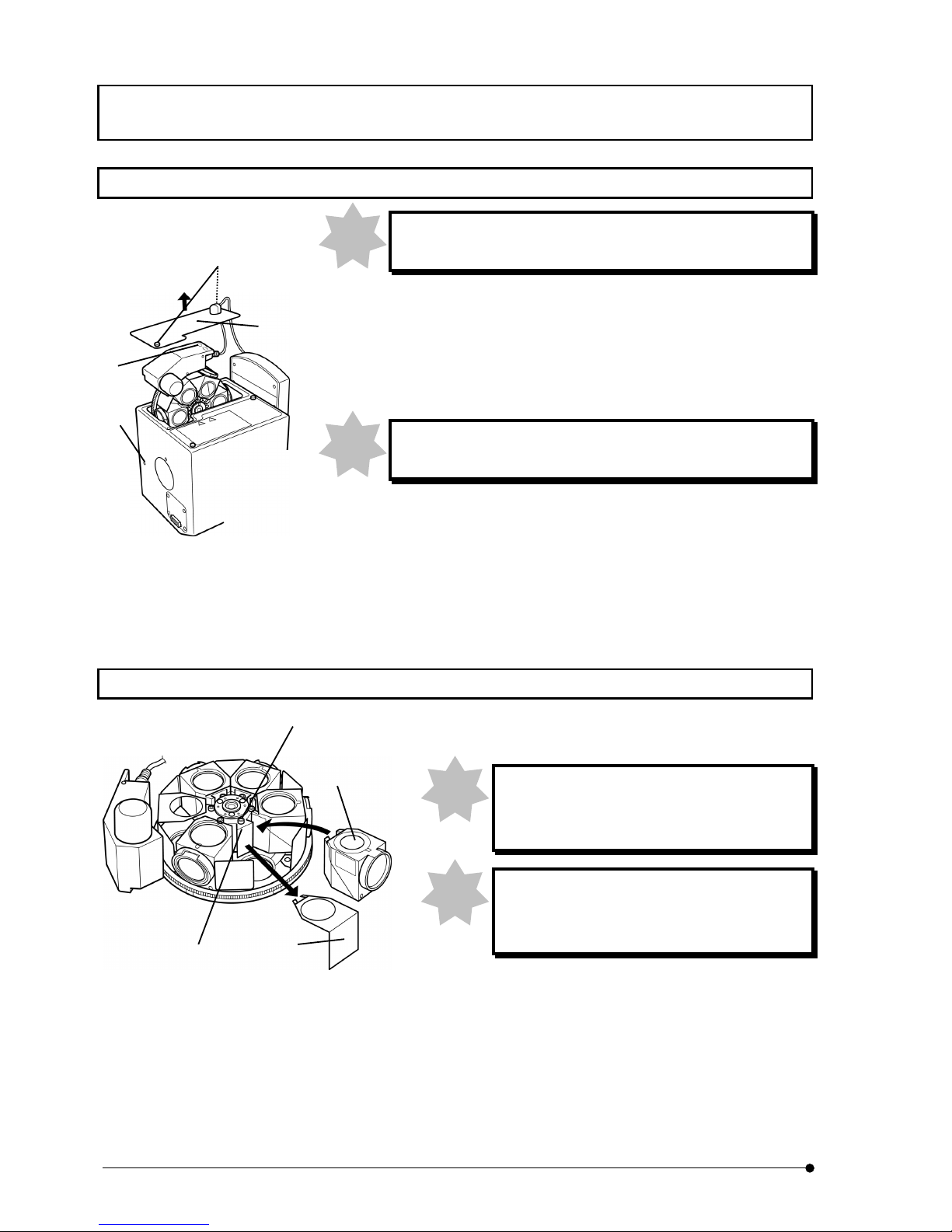
ASSEMBLY / IN/OUT of rear side turret
II .
DSU
II .
8-14
Page
8-11 IN/OUT of rear side turret
When you install or detach the turret, you must do the works
after you turn the power of control box.
1. (Removal). Loosen screws (2) (2 places) at rear side of access panel (1) on
top of disk box, using dedicated the Allen screwdriver and remove the access
panel.
2. Loosen fixing screw from hole (3) located at left side of disk box, using The
Allen screwdriver and hold the handle (4) of turret and pull it upward.
Pull out the turret gently so as not to hit mirror unit with inside
wall of disk box.
3. (Installation). Align mount dovetail of turret and mount dovetail of disk box and
push the turret from top until it hits to dead end.
4. Tighten fixing screw (3), using the Allen screwdriver.
5. Attach access panel (1) on top of disk box and tighten fixing screws (2) (2
places), using the Allen screwdriver.
8-12 Installation of camera mirror unit (rear side)
1. Loosen fixing screw (1), using the Allen screwdriver and
remove dummy mirror unit (2).
When mirror units already exist inside the
cassette, be careful so as not to touch dichroic
mirror or excitation filter with your finger.
Reference mirror of adjustment completed is
attached at No.1 position. Do not change the
position of this reference mirror.
2. Insert mirror unit (3) to be used into mount dovetail (4) of
mirror unit and push it until it hits to dead end and the, tighten
fixing screw (1), using the Allen screwdriver.
Note
Note
Note
Note
(1)
(2)
(3)
(4)
(1)
(2)
(3)
(4)
Page 69
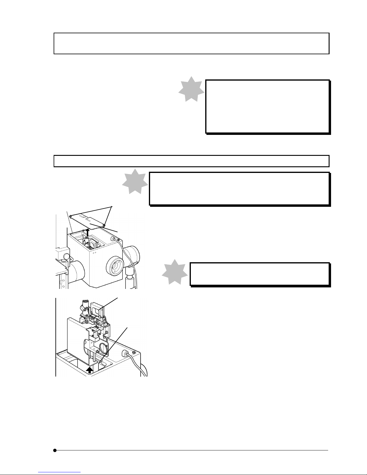
ASSEMBLY / Disk installation and change
II .
DSU
II .
8-15
Page
For camera observation, use fluorescent mirror
unit of HQ type.
The fluorescent mirror unit type DSU-MRFPHQ
– accessory of this system – is dedicated for
camera observation.
8-13 Disk installation and change
For disk installation or change, you must do the works after you
verify that the disk entered into light path and then, you turn the
power of control box.
1. Loosen screws (2) (2 places) at front side of access panel (1) located
on top of disk box, using the Allen screwdriver and remove the
access panel.
2. Loosen fixing screw from hole (3) located at left side of disk box,
using the Allen screwdriver and pull disk unit (4) upward.
Pull out disk unit gently so as not to hit disk unit with
inside wall of disk box.
3. Loosen knob of disk unit (5) (2 places) and open disk cover (6).
4. In case that transportation lock knob is attached instead of disk,
remove the transportation lock knob first. (Regarding transportation
lock knob, see 8-4 Removal of transportation lock.) Pressing the
edge of disk, turn rotary shaft (7) in clockwise direction, using the
Allen screwdriver and remove disk attached to the disk unit (4).
5. Holding edge of disk, get out the disk that you are going to install
from the package without removing wrapper.
Note
Note
(1)
(2)
(3)
Note
(8)
(4)
Page 70
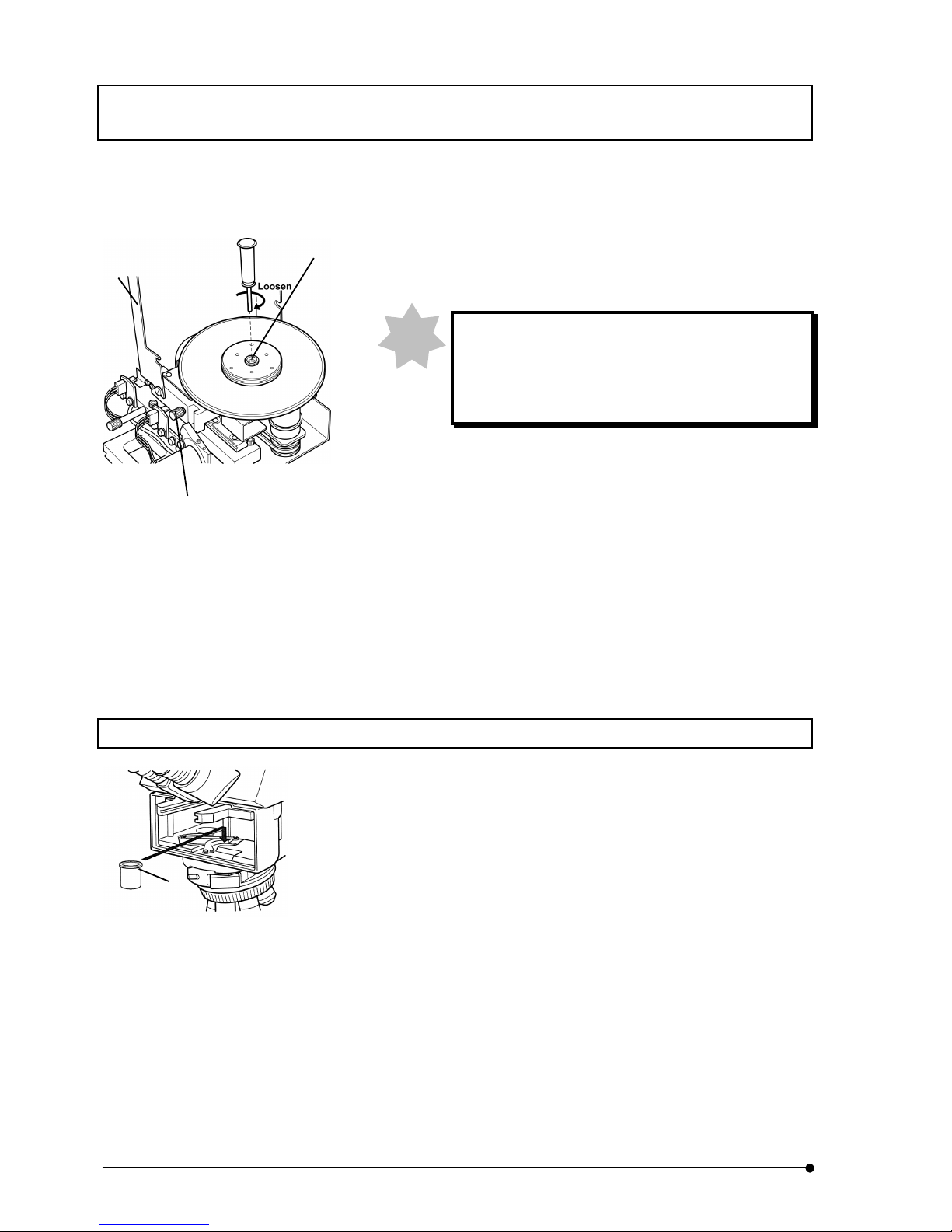
ASSEMBLY / Installation of light shielding tube (BX61, BX62, BX51 or BX52)
II .
DSU
II .
8-16
Page
6. Set the disk, putting the side attached with name seal (dark blue
side) down and, holding edge of disk, turn rotary shaft (7) in counter-
clockwise direction to screw in to the end, using the Allen screwdriver.
After fixing, remover the wrapper.
If you install disk upside down, cover (6) would not
close. If you attempt to close cover (6), it would
damage surface of disk. Therefore, attach the disk in
correct direction.
7. Return disk cover (6) to original position and tighten knob (5) of disk
unit (2 places) and fix the cover.
8. The disk removed should be kept in the packet. Transport lock knob
should be attached to the disk unit.
9. Align dovetail of disk unit (4) and dovetail of disk box (8) and push it
from top to dead end.
10. Tighten fixing screw (3), using the Allen screwdriver.
11. Attach access panel (1) on top of disk box and tighten fixing screws
(2) at two places, using the Allen screwdriver.
8-14 Installation of light shielding tube (BX61, BX62, BX51 or BX52)
1. Remove front side turret. For removal of front side turret, see 8-9
Installation of front side turret.
2. Set light shielding tube inside the light illuminator.
(1)
Note
(6)
(7)
(5)
(both sides)
Page 71
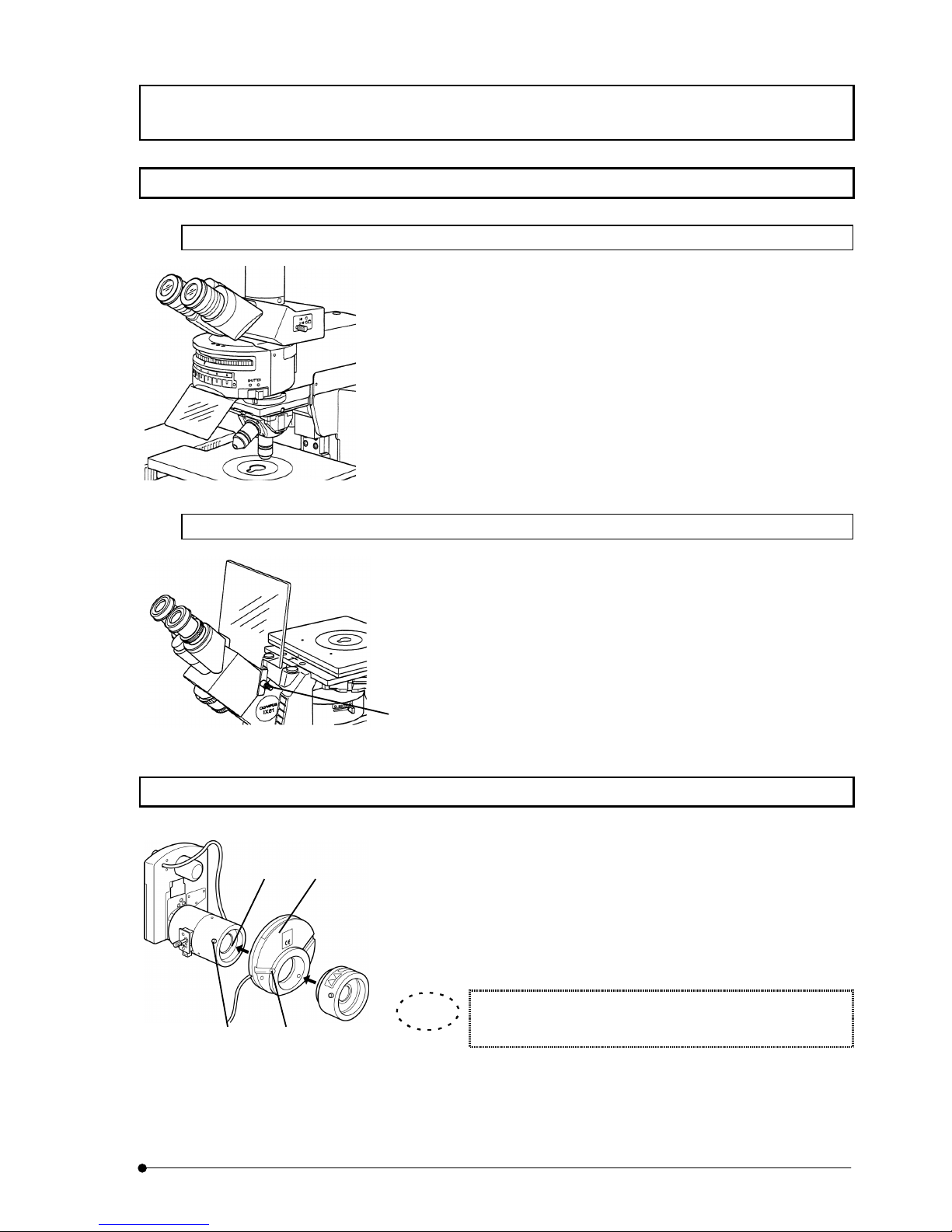
ASSEMBLY / Installation of UV-cut plate
II .
DSU
II .
8-17
Page
8-15 Installation of UV-cut plate
8-15-1 In case of BX
1. Put UV-cut plate underneath the front side mirror turret as illustrated.
8-15-2 In case of IX
1. Loosen fixing knob (1) for UV-cut plate.
2. Put the UV-cut plate in receptacle of lens barrel of microscope frame as
illustrated.
3. Turn fixing knob to fix firmly.
8-16 Installation of filter or shutter (In case of U-FWR or IX2-SHA)
1. Loosen fixing screws (1) that fix lamp house mount adapter at two
places and remove the lamp house mount adapter.
2. Insert filter or shutter (2) that you are going to use into mount (3) and
tighten fixing screws (1) at two places.
3. Insert lamp house mount adapter into filter wheel or shutter (2) that you
are going to use and then, tighten fixing screws (4) at two places.
Installation of LAMBDA 10 and Ludl filter is the same as
described above.
(2)(3)
(4)(1)
TIP
(1)
Page 72
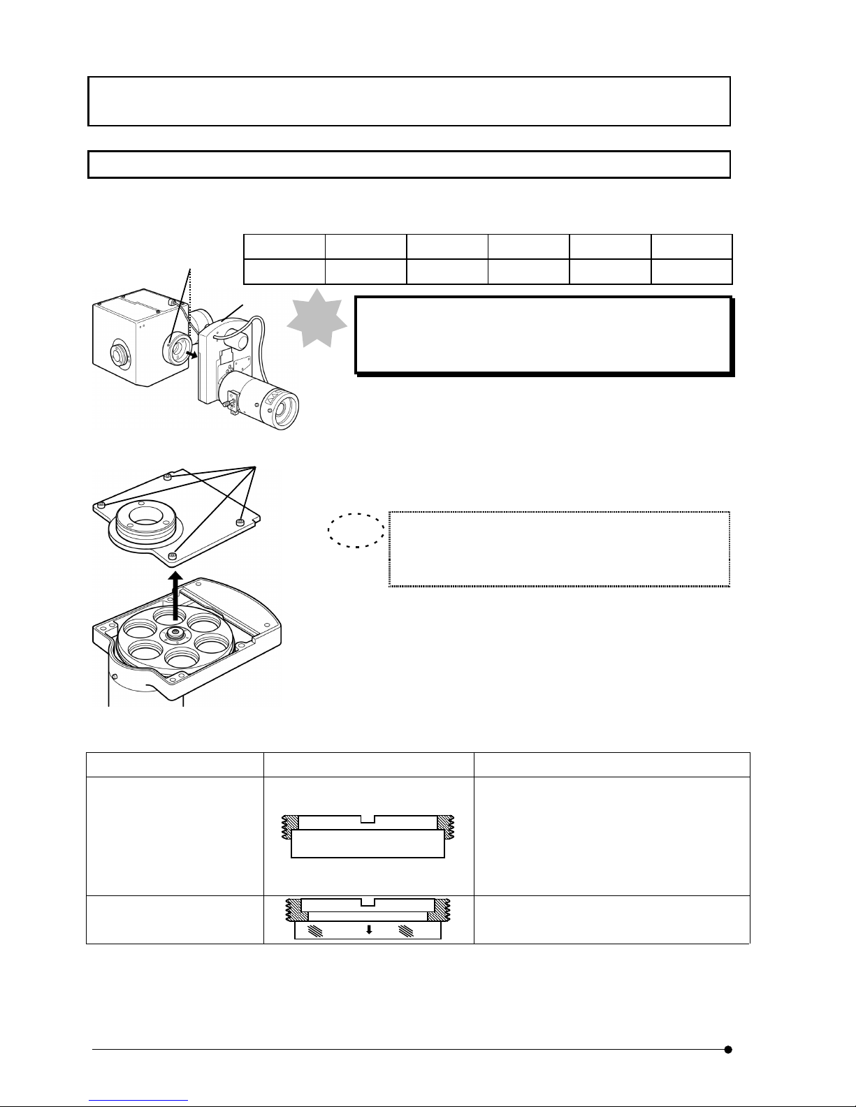
ASSEMBLY / Filter IN/OUT inside motorized filter wheel
II .
DSU
II .
8-18
Page
8-17 Filter IN/OUT inside motorized filter wheel
At ex-factory, filters are attached as shown in the following table. When you wish to
change the setting, follow to the following procedures.
No.1 No.2 No.3 No.4 No.5 No.6
Empty ND25 ND12 ND6 ND3 ND1.5
In case of installation or removal of filter, you must turn power
of control box. In addition, you must remove cable from
control box.
1. Remove lamp house and filter unit of option.
2. Loosen fixing screws (1) of mount for illuminator at two places, using
the Allen screwdriver and remove filter wheel (2).
3. Loosen fixing screws (3) of filter wheel cover at four places, using the
Allen screwdriver and remove the cover.
Filter is of 32mm diameter (25mm diameter, use conversion
adapter* ) and thickness should be up to 6mm. Direction of
presser ring is shown in the following table by the thickness.
* Conversion adapter for 25mm diamter is available at option. When
you need it, contact local sales office. (AD6921 and AB9169)
Thickness of filter Direction of presser ring Remarks
• 4mm or more, 6mm or less
• U-FWCO1.25X
• U-FW32PO
• Insert U-FWCO1.25X with 29.6mm diameter
side down
• Insert U-FW32PO into No.1 hole for sure.
(Alignment pin and slot must be matched with
each index).
• 4mm or less
• Conversion adapter
(Installation method of 25mm filter to conversion adapter is the same as described above).
Note
TIP
(2)
(3)
(1)
Page 73
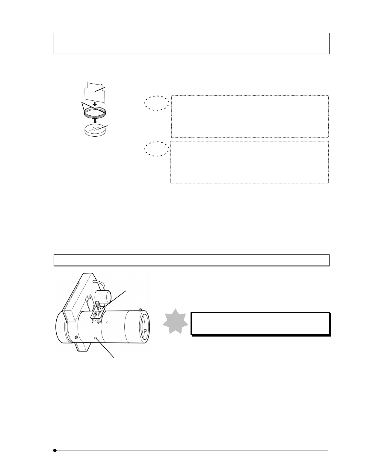
ASSEMBLY / Field iris diaphragm IN/OUT
II .
DSU
II .
8-19
Page
4. Insert presser ring driver (4) into slots (5) of presser ring and turn it in
clockwise direction to fix the filter (6).
When you attach filter of 25mm diameter to conversion adapter,
use small side of presser ring driver (4).
Be careful when you attach conversion adapter as the portion to
insert filter is slanted by 5°.
Arrow mark is provided on side of barrier Filter and excitation
filter.
Barrier Filter: Insertion must be matched with arrow.
Excitation filter: Insertion must be made in reverse with arrow.
5. When you finished installation of all filters required, return the filter wheel
cover to original position and fix it by tightening four fixing screws (3).
6. Insert filter wheel (2) into illuminator and tighten fixing screws (1) of mount
at two places, using the Allen screwdriver.
7. Attach lamp house and optional filter unit to original position respectively.
8-18 Field iris diaphragm IN/OUT
1. (Removal). Loosen fixing screw (1) located at the bottom of aperture
unit, using the Allen screwdriver.
2. Hold aperture unit (2) and pull it horizontally.
3. (Installation). Reverse procedure 1 and 2.
When you tighten fixing screw (1), tighten it lightly.
Do not tighten it too hard.
(4)
(5)
(6)
TIP
TIP
(1)
(2)
Note
Page 74
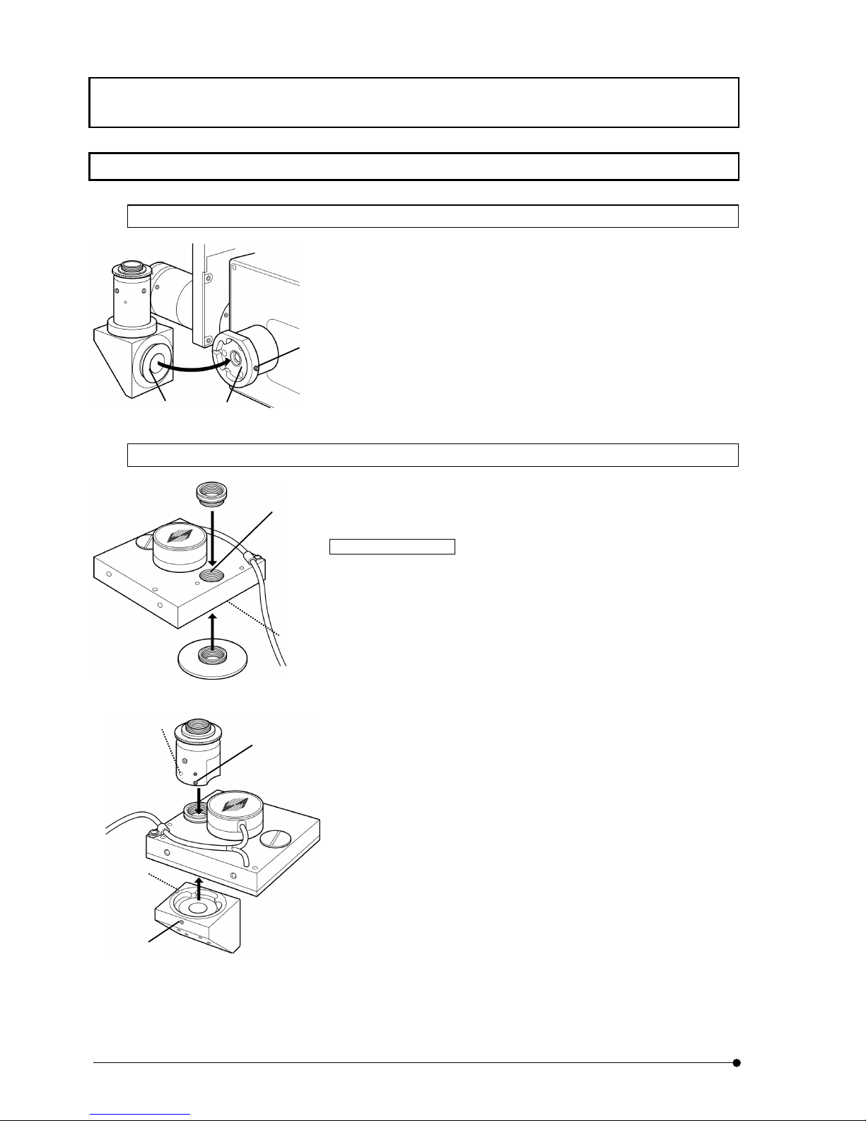
ASSEMBLY / Installation of camera adapter and filter
II .
DSU
II .
8-20
Page
8-19 Installation of camera adapter and filter
8-19-1 In case of DSU C-mount adapter
1. Loosen fixing screw (1), using the Allen screwdriver.
2. Insert C-mount adapter (3) into disk box (2).
3. Tighten fixing screw (1), using the Allen screwdriver.
8-19-2 C-mount adapter for DSULAMBDA10 / C-mount adapter for Ludl
In case of LAMBDA10
1. Screw in the upper adapter and lower adapter by turning them into
threaded holes (1) and (2) of C-mount for filter wheel and fix them
firmly as illustrated.
2. Align filter wheel with red index (3) of port as illustrated and tighten
screws (4) at three places, using tool that comes with the system as
accessory.
3. Attach filter wheel to mirror holder in a way that red index (3) of port
and red index (5) of mirror holder are aligned each other.
4. Tighten fixing screw (6), using the Allen screwdriver.
(1)
(2)(3)
(1)
(2)
(4)
(3)
(Red index)
(5)
(Red index)
(6)
Page 75
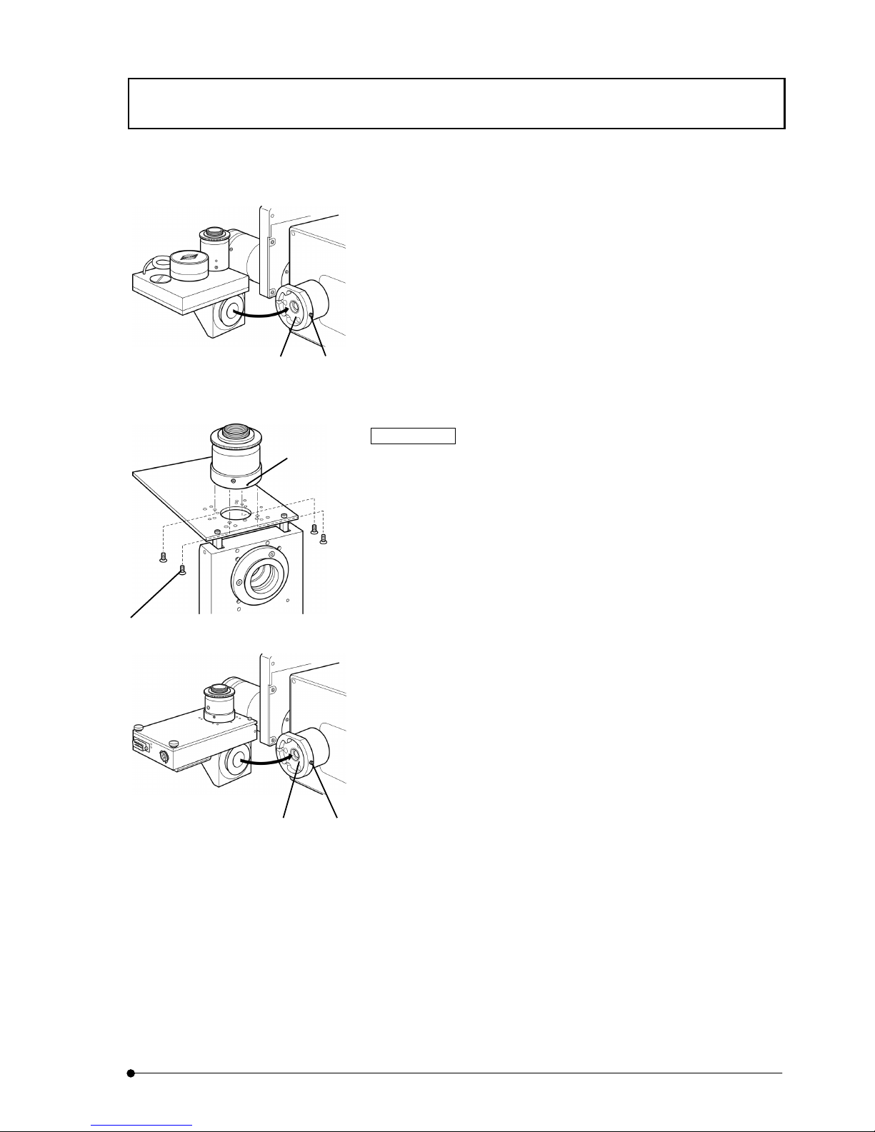
ASSEMBLY / Installation of camera adapter and filter
II .
DSU
II .
8-21
Page
5. Loosen fixing screw (7) of disk box, using the Allen screwdriver.
6. Insert C-mount adapter that is attached with filter wheel into mount
(8) of disk box.
7. Tighten fixing screw (7), using the Allen screwdriver.
In case of Ludl
1. Open lid of filter wheel and remove adapter that is attached from the
beginning, using Philips type + screwdriver.
2. Align direction with red index (9) of port as illustrated and fasten four
screws (10) that come as accessories from within, using Philips
type + screwdriver.
3. Assemble C-mount adapter as in the procedure 3 and 4 of
LAMBDA10.
4. Loosen fixing screw (11) of disk box, using the Allen screwdriver.
5. Insert C-mount adapter that is attached with filter wheel into mount
(12) of disk box.
6. Tighten fixing screw (11), using the Allen screwdriver.
(8) (7)
(9)
(10)
(11)(12)
Page 76
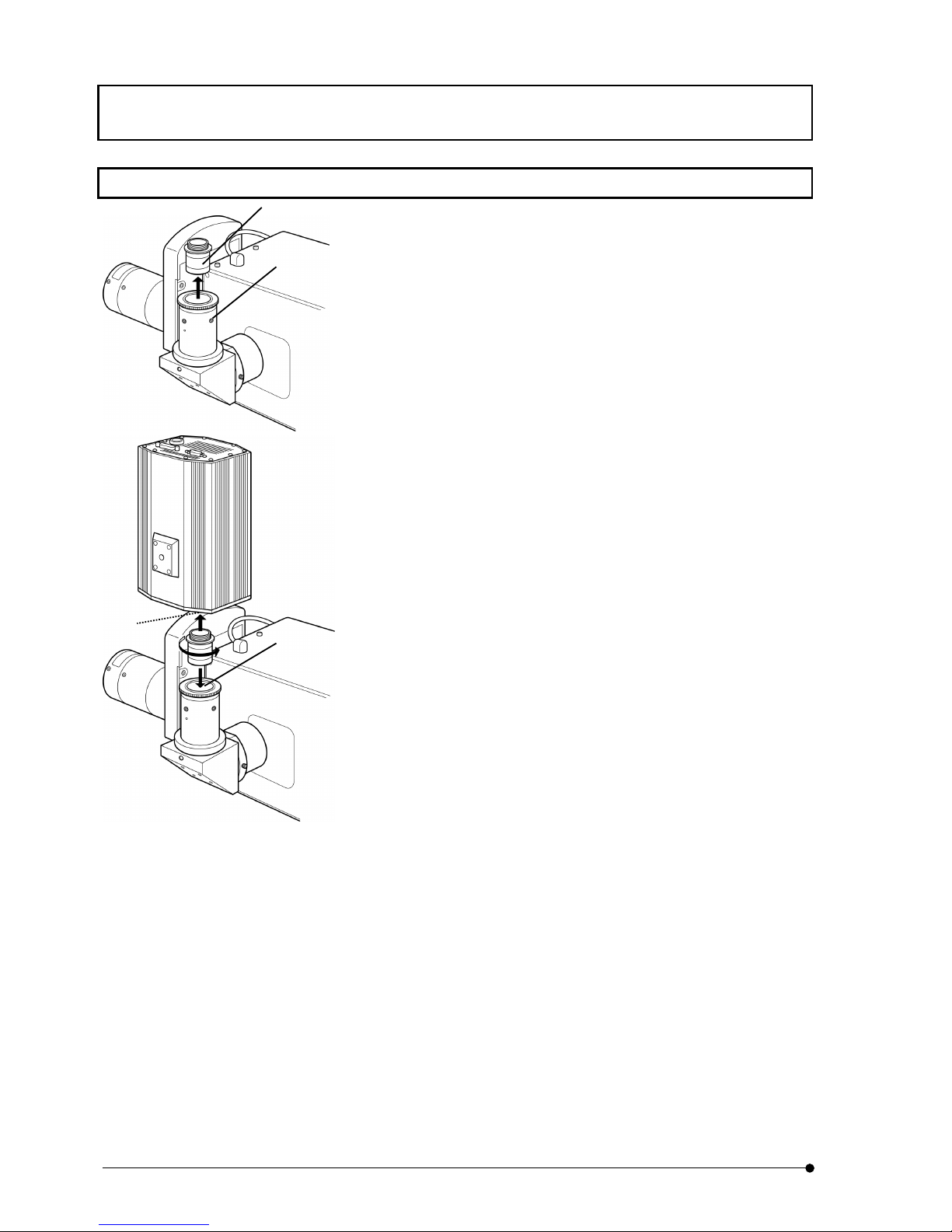
ASSEMBLY / Installation of camera
II .
DSU
II .
8-22
Page
8-20 Installation of camera
1. Loosen fixing screw (1) of port, using the Allen screwdriver that comes
as accessory for microscope frame and remove C-mount adapter (2)
inside the port.
2. Screw in and fix the C-mount adapter(2) that was removed to C-mount
section (3) of camera firmly.
3. Insert C-mount adapter that is attached with camera into port (4)
gently.
4. Tighten fixing screw (1) at least one place, using the Allen
screwdriver.
(1)
(2)
(3)
(4)
Page 77
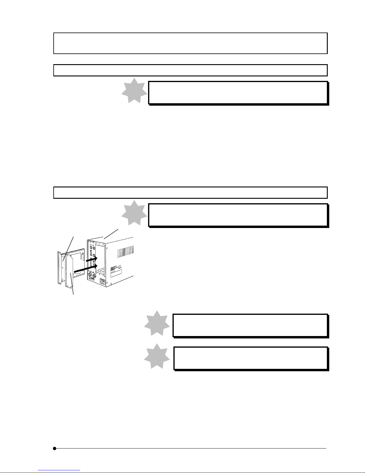
ASSEMBLY / DIP switch settings on control box (BX61, BX62 and BX61W1 only)
II .
DSU
II .
8-23
Page
8-21 DIP switch settings on control box (BX61, BX62 and BX61W1 only)
DIP switch settings should be done after power of control box is
turned OFF.
When you use BX61, BX62 or BX61W1, you must change DIP switch settings on control
box. Set in accordance with the following procedures.
1. Peel off the seal in front of SW1.
2. Change DIP switch 7 to ON.
3. Attach front seal to SW1.
8-22 Installation of motor drive board
You must install motor drive board after you turn power of control
box to OFF.
1. Loosen four fixing knobs for two option slot covers at left side of back panel
of control box (1) and remove covers and knobs.
2. Aligning direction of connector inside control box with connector (2), insert
the board along with board rails.
Push the board until connectors of motor drive board are inserted into
connectors of mother board inside the control box.
3. Using knobs you removed, fix motor drive board (2).
Likewise, attach the other cover (3).
Slot cover section must overlap. Attach cover from left side,
seen from back side.
Keep one piece of slot cover that remained with care as it
may be required for motor drive board when it is removed.
Note
(1)
(2)
(3)
Note
Note
Note
Page 78
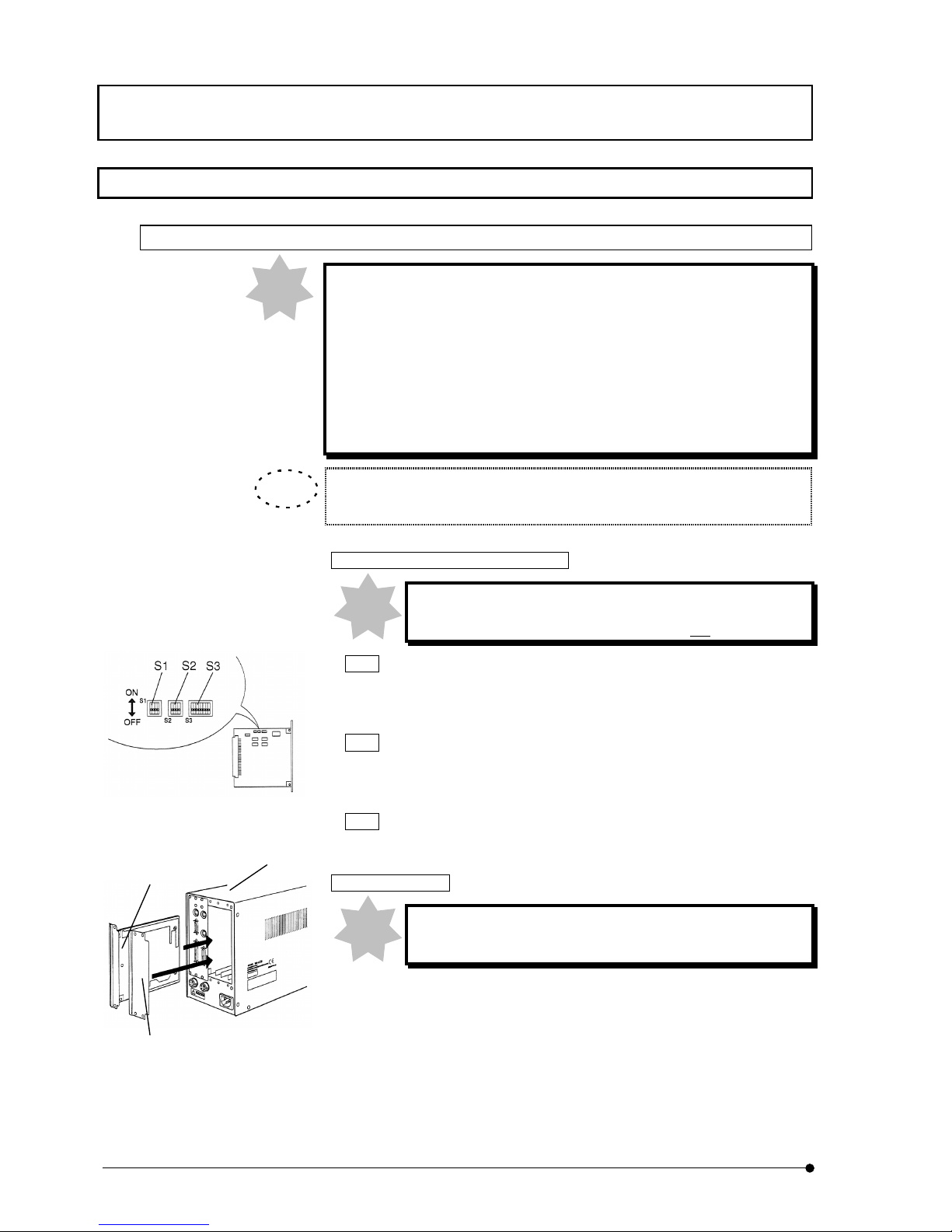
ASSEMBLY / Z board setting and installation
II .
DSU
II .
8-24
Page
8-23 Z board setting and installation
8-23-1 In case of BX61 and BX62
For Z board, use type U-ZPCB(T2) for sure.
In case that U-ZPCB(T2) or subsequent is not used, the following
troubles may occur even if correct setting was done.
●
Rotation of focusing handle and actual objective lens movement would
be reversed.
●
Focusing control may not be able to initialize, depending upon the
position. (Microscope does not boot up).
All DIP switches on Z board, S1, S2 and S3 are turned to OFF at ex-factory.
Setting change of ONBOARD DIP SW
Use DIP SW set to OFF except the following DIP SW.
Turn DIP SW that is to be changed only to ON .
S2 NO.4
• Interchanges F/C change button and Stage retreat button located at left
side of BX61/BX62 to Stage DOWN button and Stage UP button.
S3
NO.1
• Automatic initializing function is turned to OFF and default remote state
is set.
S3
NO.4
• Stroke of focusing control is changed from 15mm to 25mm.
Z board installation
You must install Z board after you turn power of control box
to OFF.
1. Loosen fixing knobs (6 pieces) for two slot covers at back side of control
box (1) and remove covers and knobs.
2. Aligning direction of connector of control box and connector of Z board
(2), insert board along with board rails. Push in until connectors are
firmly connected.
Note
(1)
(2)
(3)
TIP
Note
Note
Page 79
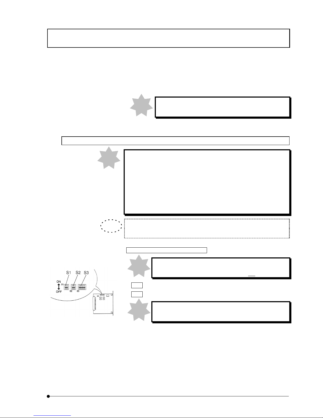
ASSEMBLY / Z board setting and installation
II .
DSU
II .
8-25
Page
3. Using knobs you removed, fix Z board (2). Likewise, attach the other
cover (3).
Keep one piece of slot cover that remained with care as it
may be required for Z board when it is removed.
8-23-2 In case of BX61W1
For Z board, use type U-ZPCB(T2) for sure.
In case that U-ZPCB(T2) or subsequent is not used, the following
troubles may occur even if correct setting was done.
●
Rotation of focusing handle and actual objective lens movement would
be reversed.
●
Focusing control may not be able to initialize, depending upon the
position. (Microscope does not boot up).
All DIP switches on Z board, S1, S2 and S3 are turned to OFF at ex-factory.
Setting change of ONBOARD DIP SW
Use DIP SW set to OFF except the following DIP SW.
Turn DIP SW that is to be changed only to ON .
S2 Changes NO.2 and NO.3 to ON.
S3
Changes NO.2, NO.4 and NO.5 to ON.
If DIP switches are not correctly set, objective lens comes
down and hits the specimen.
Note
Note
TIP
Note
Note
Page 80
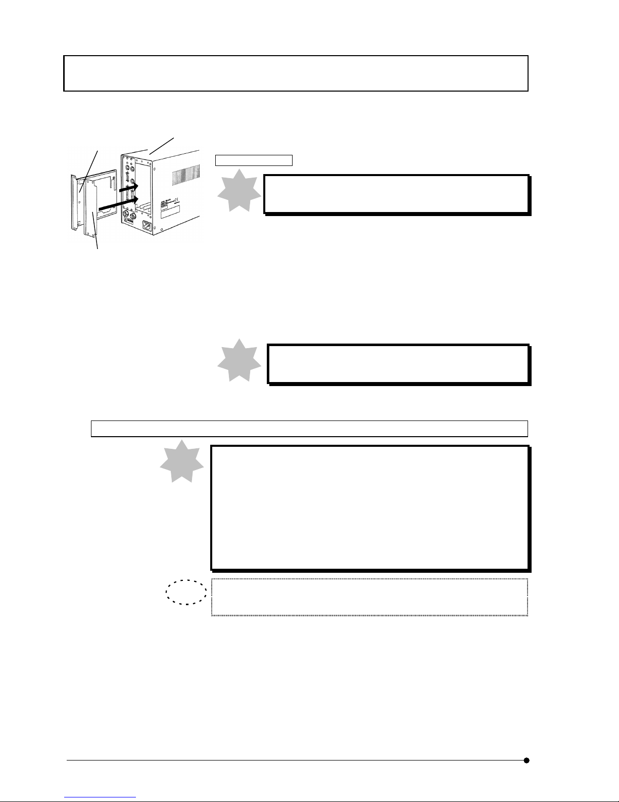
ASSEMBLY / Z board setting and installation
II .
DSU
II .
8-26
Page
Z board installation
You must install Z board after you turn power of control box
to OFF.
1. Loosen fixing knobs (6 pieces) for two slot covers at back side of control
box (1) and remove covers and knobs.
2. Aligning direction of connector of control box and connector of Z board
(2), insert board along with board rails.
Push in until connectors are firmly connected.
3. Using knobs you removed, fix Z board (2). Likewise, attach the other
cover (3).
Keep one piece of slot cover that remained with care as it
may be required for Z board when it is removed.
8-23-3 In case of IX81
For Z board, use type U-ZPCB(T2) for sure.
In case that U-ZPCB(T2) or subsequent is not used, the following
troubles may occur even if correct setting was done.
●
Rotation of focusing handle and actual objective lens movement would
be reversed.
●
Focusing control may not be able to initialize, depending upon the
position. (Microscope does not boot up).
All DIP switches on Z board, S1, S2 and S3 are turned to OFF at ex-factory.
Note
Note
Note
TIP
(1)
(2)
(3)
Page 81
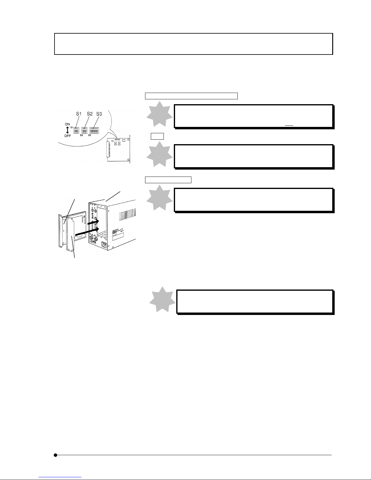
ASSEMBLY / Z board setting and installation
II .
DSU
II .
8-27
Page
Setting change of ONBOARD DIP SW
Use DIP SW set to OFF except the following DIP SW.
Turn DIP SW that is to be changed only to ON .
S3 Changes NO.4 and NO.5 to ON.
If DIP switches are not correctly set, objective lens comes
down and hits the specimen.
Z board installation
You must install Z board after you turn power of control box
to OFF.
1. Loosen fixing knobs (6 pieces) for two slot covers at back side of control
box (1) and remove covers and knobs.
2. Aligning direction of connector of control box and connector of Z board
(2), insert board along with board rails.
Push in until connectors are firmly connected.
3. Using knobs you removed, fix Z board (2). Likewise, attach the other
cover (3).
Keep one piece of slot cover that remained with care as it
may be required for Z board when it is removed.
(1)
(2)
(3)
Note
Note
Note
Note
Page 82

Page 83

Page 84

OLYMPUS CORPORATION
2-43-2,Hatagaya, Shibuya-ku, Tokyo, Japan
OLYMPUS OPTICAL CO.(EUROPA) GMBH.
Postfach 10 49 08, 20034, Hamburg, Germany
OLYMPUS AMERICA INC.
2 Corporate Center Drive, Melville, NY 11747-3157, U.S.A.
OLYMPUS SINGAPORE PTE LTD.
491B River Valley Road, #12-01/04 Valley Point Office Tower, Singapore 248373
OLYMPUS OPTICAL CO. (U.K.) LTD.
2-8 Honduras Street, London EC1Y OTX, United Kingdom.
OLYMPUS AUSTRALIA PTY. LTD.
104 Ferntree Gully Road, Oakleigh, Victoria, 3166, Australia
Printed in Japan 2003 10
1.3
 Loading...