

Page 1

E-20/E-20N/E-20P
C. ADJUSTMENT METHOD
[ 1 ] List of Adjustment Items..................................................................C-2
1-1. List .................................................................................................C-2
1-2. Adjustment Timing......................................................................C-2
2. Installation of adjustment software ..............................................C-2
3. Installation of USB port driver ......................................................C-3
[ 2 ] Adjustment method...........................................................................C-5
1. Adjustment screen.........................................................................C-5
2. Adjustment Data COPY to FLASH ROM ...................................... C-5
3. AF Illuminator Adj...........................................................................C-6
4. AF Adj...............................................................................................C-7
5. CCD defect detect Adj ...................................................................C-8
6. Adjustment Data Save ................................................................C-10
C-1 Ver.0.5
Page 2
C.ADJUSTMENT METHOD
E-20/E-20N/E-20P
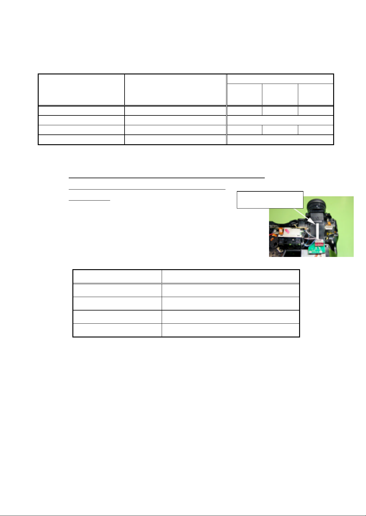
[ 1 ] List of Adjustment Items
1-1.List
Adjustment Timing for replaced parts
Adjustment Items Adjustment Operations
1)FLASH ROM Data Transfer
2)AF illuminator Adj. When an AF unit was removed.
3)AF Adj.
4)CCD defect detect Adj In the case of CCD defect
Note1) (*) When MC PWB is changed, "Adjustment Data Save." is done, and the adjustment data which are in
Flash Rom are kept in the PC. "FLASH ROM Data Transfer" is done after MC PWB is changed.
Please contact to Olympus-TSD if the data cannot be transferred from MC PWB.
Let us know the following number of bar code on finder for E-10.
We provide data.
Note2) The order of adjustment should be the following.
1) → 2)→3) →4)
Note3) (*3) You don ’t have to adjust if the data in old MC PWB is transferred to new
MC PWB.
CCD- Lens#MC PWB
#-3
○ ○(*)
○ ○(*3) ○
0013xxxxxxxxxxxxxx
AF #
1-2.Adjustment Timing
Items Adjustment Timing
1)FLASH ROM Data Transfer
2)AF illuminator Adj.
3)AF Adj.
4)CCD defect detect Adj.
2. Installation of adjustment software
2-1.PC condition
1) Pentium-equipment DOS/V computer (IBM PC/AT)
2) Windows 98 SE
3) USB port
2-2.Method of installation
Run “Set up . exe” in Floppy Disk .
(The software is installed in folder “ C:¥DI¥E-10_vb” )
2-3.Method of start
Before assembling Rear cover#
Before assembling Rear cover#
After assembling all
After assembling all
Run “E-10_VB.exe” in folder “ C:¥DI¥E-10_vb”.
C-2 Ver.0.5
Page 3
E-20/E-20N/E-20P C.ADJUSTMENT METHOD
3. Installation of USB port driver
1) The terminal (the big one) of the USB cable connects to USB port on the personal computers, and the
other terminal (the little one) connects to the camera.
2) Turns on the camera and set the mode dials to the communication mode.
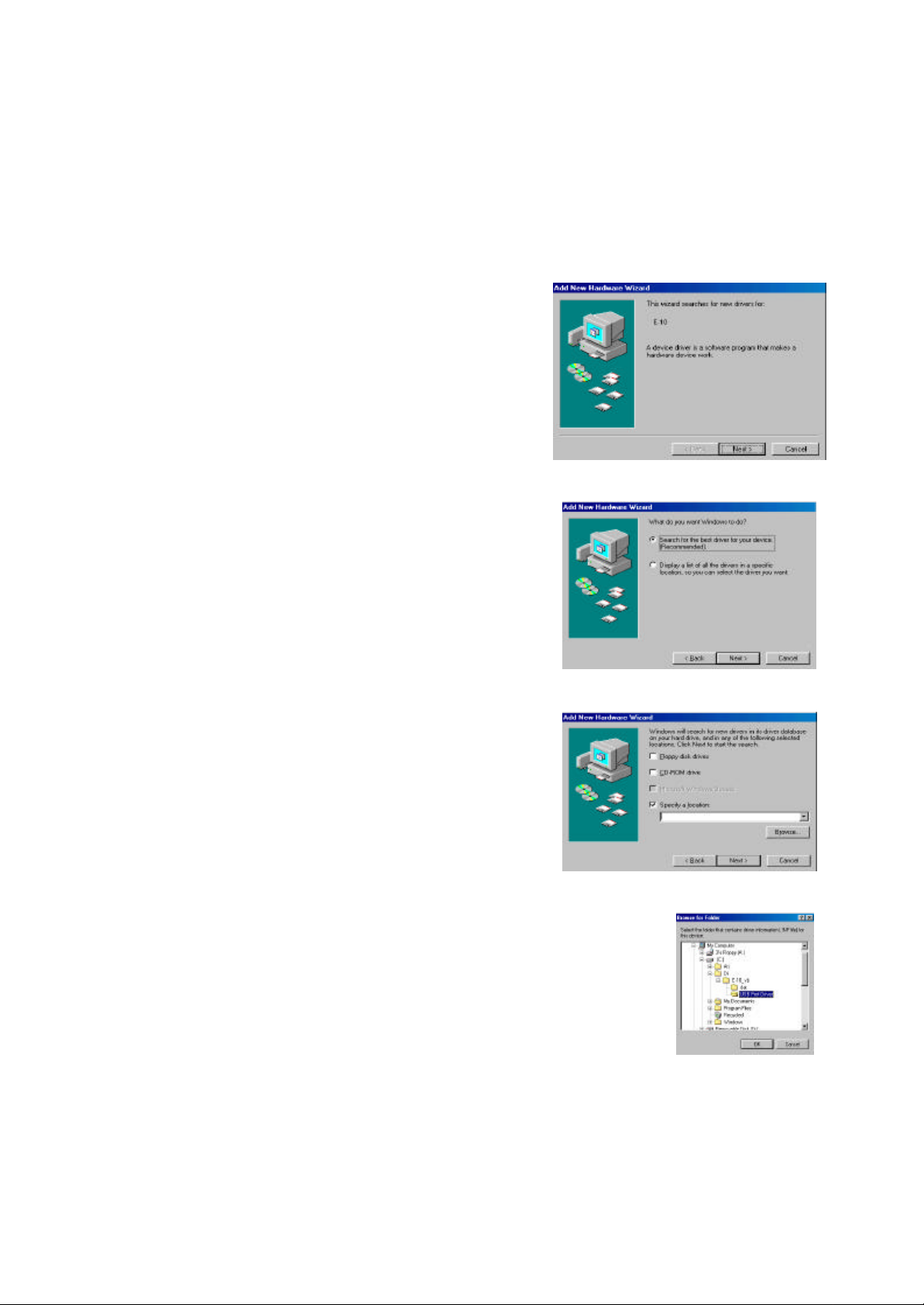
3) It is recognized as a new hardware.
Click [Next]. (Fig-1)
4) Confirms that [Search for the best driver for your
device. [Recommended]] is chosen, and clicks on
[Next]. (Fig-2)
5) Check [Specify a location].
Fig-1
Fig-2
Fig-3
Click [ Browse ] .(Fig-3)
6) [ Browse for Folder ]
Chose “C:¥DI¥E-10_vb¥USB Port Driver” on [Browse for Folder]
window.
Click [OK]. (Fig-4)
Fig-4
Ver.0.5 C-3
Page 4

C.ADJUSTMENT METHOD
E-20/E-20N/E-20P
7) Click [ Next ]. (Fig-5) (Fig-6)
Fig-5 Fig-6
8) Click [ Finish ] . The installation completion of the USB driver. (Fig-7)
Fig-7
C-4 Ver.0.5
Page 5

E-20/E-20N/E-20P C.ADJUSTMENT METHOD
[ 2 ] Adjustment Method
1. Adjustment screen
Main Menu
2. Adjustment Data COPY to FLASH ROM
(*) Power on after connecting the USB cable.
Fig-1
Adjustment Data
COPY to
FLASHROM
DATA floppy disk is
set on floppy disk
drive.
[ Data Copy ]
Click
Open Data file from
the floppy disk.
Copy Adjustment
Data
Select type
NTSC / PAL
OK ?
NO
YES
Fig-1
(*) Read the data saved into the PC. (When MC PWB was
changed.)
Folder : C:¥DI¥E-10_vb¥Data Save
File Name: "serial NO." .csv
<Select the video output NTSC / PAL>
・ Select type NTSC or PAL.
Clicks [OK]. (Fig-3)
Fig-3
END
Ver.0.5 C-5
Page 6

C.ADJUSTMENT METHOD
E-20/E-20N/E-20P
3. AF Illuminator Adj.
Servicing tools
AF Illuminator Adj Chart
(*) Power on after connecting the USB cable.
AF Illuminator
Adj
Fig-1
Fig-4
Adhesive is torn off.
(adjustment screw
and the shaft)
Fig-1
Lead line, solder
Fig-2
An adjustment screw are
turned,and the window
of the AF unit is turned
to about the front.
AF An Illuminator
Adj chart Set
[ 2.5m ]
1
The white bar of the AF
Fig-3
Illuminator Adj chart is
set lengthwise.
A zoom is made TELE,
and the square target
mark of the white square
of the AF chart and the
finder is checked.
[ AF Illuminator Adj ]
Click
A X axis adjustment
screw is turned,and
looked for peak value.
NO
Peak value?
YES
The white bar of the AF
Illuminator Adj chart is
set at the side.
A Y axis adjustment
screw is turned,and
looked for peak value.
NO
Peak value?
YES
remove the white bar
of the AF Illuminator
Adj chart .
NO
Peak value?
YES
[ Stop ]
Click
Fig-2
1
Fig-3
Fig-5
Adjustment screw
and a shaft are glued.
(super X White).
END
Fig-4
Fig-5
High Data (Reference)
Low Data (Reference)
C-6 Ver.0.5
Page 7

E-20/E-20N/E-20P C.ADJUSTMENT METHOD
4. AF Adj.
Servicing tools
Blue Chart
(*) Power on after connecting the USB cable.
Fig-1
AF Adj
[ AF Adjustment ]
Click
< AF Adjustment point and
Measurement distance Standard>
Set Zoom
[ TELE ]
Set AF chart
[ 5m ]
Adj.
Order
1. 5m 430 – 600
2. 3m 495 – 575
3. 1m 580 – 635
4. 0.6m 640 – 695
5. Infinity 0 – 20
Measurement
distance point
Standard value
AF distance
measurement
Infinity ?
NO
Set an AF chart
on the specified
distance.
Fig-1
END
Note) Cover the AF illuminator window with Black tape
when it is infinity.
YES
Ver.0.5 C-7
Page 8

E-20/E-20N/E-20P
5. Adjustment Data Save
Temperature of adjustment
15 to 35 degrees
Fig-1
CCD defect
detect Adj
[ Late CCD Defect Adj ]
Click
[ Start ]
Click
C.ADJUSTMENT METHOD
Error code
1)Connect AC adapter
and USB cable
2)Attach lens cap
and close eyepiece shutter
3)Set communication mode
and power on
[ Yes ]
Click
[ OK ]
Click
X
Judge
〇
END
Good (¡) or no good (X)
Next page shows error code.
C-8 Ver.0.5
Page 9

E-20/E-20N/E-20P C.ADJUSTMENT METHOD
When "X" was indicated in good /no good decision indication and a defect was judged.
Take the following measures referring to the error code indication.
Error code Cause (estimated cause) How to deal with it
R-1700 There is no detect for CCD defect
which occurred later
R-1025
R-1026
R-1515
R-1516
R-1510 R-1511 It has the possibility that covering
R-1603
R-1605
R-1900
〜
R-1907
R-8000
〜
Others It has possibility in the mechanism
Adjustment environment
temperature or camera inside
temperature is not suitable for the
adjustment.
such as lens cap or eyepiece is
imperfect.
There might be many CCD defects
which occurred later.
It is a defect related to the USB
communication between the host
PC-cameras.
It is the defect that relates to OS
(Windows) of the host PC.
inside the camera and so on a
trouble.
Carry out re-adjustment to five times.
The E-10 is not suitable to adjust when it becomes
the same defect even if five times are adjusted again.
Refer to ※1.
Look over a temperature condition again, and adjust it
again.
Moreover, it can think that camera inside temperature
rises when a camera was continued and made to work.
Adjust it again after you put constant time.
Reconfirm covering conditions, and adjust it again.
The E-10 is not suitable to adjust if there is no problem
in the covering condition of the camera.
Check the connection of the mode setup/cable of
the camera and so on, and adjust it again.
Do re-adjustment after the re-check such as the
setup, setting up of OS.
Stop this adjustment, and do the repair of the
trouble place.
※1: Most cases are judged a "R-1700" defect when the body which has a good
decision (「○」 indication) done once is adjusted again.
And, it is judged a "R-1700" defect in the same way when the good body doesn't
exist CCD defect which occurred later.
Therefore, contents of this treatment are available to first repair for CCD defect
detect Adj that fails.
Ver.0.5 C-9
Page 10

C.ADJUSTMENT METHOD
E-20/E-20N/E-20P
6.Adjustment Data Save
Preserve the adjustment value of FlashRom in the PC.
Folder: C:¥DI¥E-10_vb¥Data Save
File Name: “serial No.”.csv
C-10 Ver.0.5
 Loading...