

Page 1

C. ADJUSTMENT METHOD
E-100RS
C. ADJUSTMENT METHOD
[1] TABLE FOR SERVICING TOOLS........................................................................ C-2
[2] EQUIPMENT ......................................................................................................... C-2
[3] ADJUSTMENT ITEMS AND ORDER................................................................... C-2
[4] SETUP .................................................................................................................. C-2
[5] CONNECTING THE CAMERA TO THE COMPUTER .........................................C-3
[6] ADJUSTMENT ..................................................................................................... C-4
1. 15.2V(A) VOLTAGE ADJUSTMENT .............................................................. C-4
2. IC501 OSCILLATION FREQUENCY ADJUSTMENT....................................C-4
3. IC502 OSCILLATION FREQUENCY ADJUSTMENT....................................C-4
4. 13.0V(L) VOLTAGE ADJUSTMENT .............................................................. C-4
5. HALL ELEMENT ADJUSTMENT .................................................................. C-4
6. AF LED ANGLE ADJUSTMENT ................................................................... C-5
7. AWB ADJUSTMENT ..................................................................................... C-5
8. LENS ADJUSTMENT .................................................................................... C-5
9. CCD DEFECT ADJUSTMENT ...................................................................... C-5
10. EIS SHIFT LENS ADJUSTMENT ................................................................ C-6
11. LCD PANEL ADJUSTMENT .......................................................................C-6
11-1. LCD H AFC ADJUSTMENT .................................................................C-6
11-2. LCD GAIN ADJUSTMENT ................................................................... C-6
11-3. LCD RGB OFFSET ADJUSTMENT ..................................................... C-6
11-4. LCD RED BRIGHTNESS ADJUSTMENT ........................................... C-6
11-5. LCD BLUE BRIGHTNESS ADJUSTMENT .........................................C-7
11-6. LCD TINT ADJUSTMENT(FOR PAL) ..................................................C-7
12.EVF ADJUSTMENT ..................................................................................... C-7
12-1. EVF H AFC ADJUSTMENT ................................................................. C-7
12-2. EVF RGB OFFSET ADJUSTMENT ..................................................... C-7
12-3. EVF GAIN ADJUSTMENT.................................................................... C-8
12-4. EVF RED BRIGHTNESS ADJUSTMENT............................................ C-8
12-5. EVF BLUE BRIGHTNESS ADJUSTMENT ......................................... C-8
12-6. EVF TINT ADJUSTMENT(FOR PAL)...................................................C-9
[7] ADJUSTMENT VALUES ................................................................................... C-10
[8] ADJUSTMENT ITEMS ...................................................................................... C-11
TEST CHART ...................................................................................................... C-12,13
SERVER_DIS
C-1
Ver. 1
Page 2
C. ADJUSTMENT METHOD E-100RS
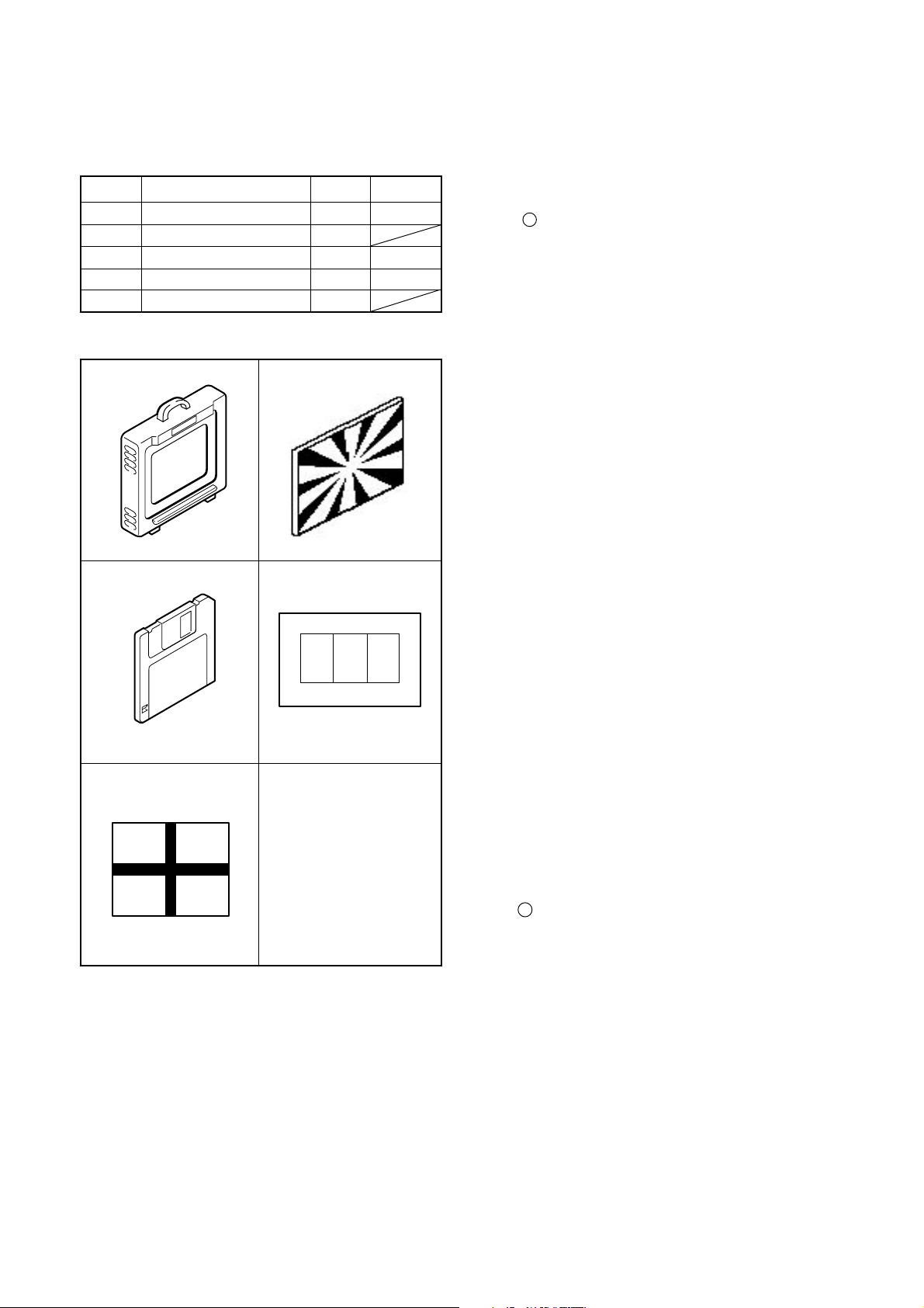
[ 1] Table for Servicing Tools
Ref. No. Name
J-1
J-2
J-3
J-4
J-5
Note: J-1 color viewer is 100 - 110 VAC only.
Color viewer 5,100 K
Siemens star chart
Calibration software
Chart for color adjustment
Shift lens adjustment chart 1
J-1 J-2
J-3
J-4
J-5
Number
1
1
1
1
Part code
VJ8-0007
VJ8-0174
VJ8-0155
[ 2 ] Equipment
1. Oscilloscope
2. Digital voltmeter
3. AC adaptor
4. IBM R -compatible PC
5. DC regulated power supply
[ 3 ] Adjustment I tems and Order
1. 15.2 V (A) Voltage Adjustment
2. IC501 Oscillation Frequency Adjustment
3. IC502 Oscillation Frequency Adjustment
4. 13.0 V (L) Voltage Adjustment
5. Hall Element Adjustment
6. AF LED Angle Adjustment
7. AWB Adjustment
8. Lens Adjustment
9. CCD Defect Detect Adjustment
10. EIS Shift Lens Adjustment
11. LCD Panel Adjustment
11-1. LCD H AFC Adjustment
11-2. LCD Gain Adjustment
11-3. LCD RGB Offset Adjustment
11-4. LCD Red Brightness Adjustment
11-5. LCD Blue Brightness Adjustment
11-6. LCD Tint Adjustment (for PAL)
12. EVF Adjustment
12-1. EVF H AFC Adjustment
12-2. EVF RGB Offset Adjustment
12-3. EVF Gain Adjustment
12-4. EVF Red Brightness Adjustment
12-5. EVF Blue Brightness Adjustment
12-6. EVF Tint Adjustment (for PAL)
Note:
1. If the lens, CCD, board and changing the part replace,
it is necessary to adjust again. Item 7-9 adjustments
should be carried out in sequence. For 9, carry out adjustment after sufficient charging has taken place.
SERVER_DIS
[4 ] Setup
1. System requirements
Windows 95 or 98
IBM R -compatible PC with Pentium processor
CD-ROM drive
3.5-inch high-density diskette drive
USB port
8 MB RAM
Hard disk drive with at least 15 MB available
VGA or SVGA monitor with at least 256-color display
2. Installing calibration software
1. Insert the calibration software installation diskette into
your diskette drive.
2. Open Explorer.
3. Copy the DSC Cal folder on the floppy disk in the FD
drive to a folder on the hard disk.
3. Installing USB drive
Install the USB drive with camera or connection kit for PC.
C-2
Ver.1
Page 3
C. ADJUSTMENT METHODE-100RS
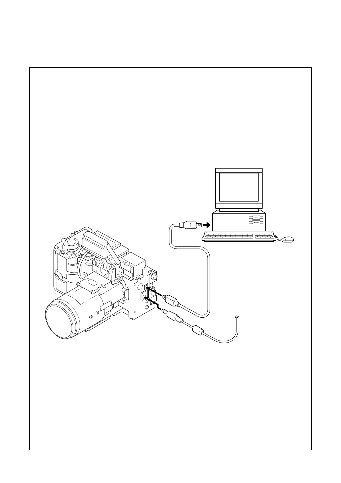
[ 5 ] Connecting the camera to the computer
1. Line up the arrow on the serial cable connector with the notch on the camera's USB port. Insert the connector.
2. Locate a USB port on the back of your computer.
To USB port
USB cable
AC adaptor
Ver.1
C-3
SERVER_DIS
Page 4
[6] Adjust Specifications
TP301
S3002
TP302
C. ADJUSTMENT METHOD E-100RS
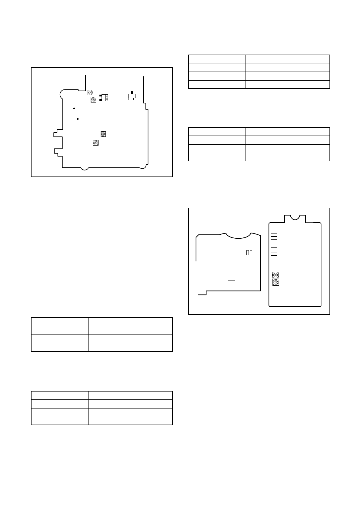
3. IC502 Oscillation Frequency Adjustment
[PW1 board (Side B)]
Q5021-
1, 2
Q5004-
collector
VR501
VR504
CL522
CL526
VR502
VR511
Note:
1. Voltage adjustment is necessary to repair in the PW1
board and replace the parts.
2. Carry out adjustment with disconnect harness for storbe.
Preparation:
1. Assemble PW1 board, CA2 board, CA4 board, SY1
board, SY2 board and TB2 board. Next, assemble holder
battery, shutter, LCD and EVF etc.
2. Connect CN304 on the SY1 board and flexible wire in
the top cabinet.
3. Insert the card.
4. Turn on the power switch, and then set the camera mode.
The lens unit will not be connected at this time, so the
camera will not display through image.
5. In case of lighting the EVF, push S1702 on the CA4 board.
Turn on the LCD.
Measuring Point
Measuring Equipment
ADJ. Location
ADJ. Value
Q5004 collector (play mode)
Frequency counter
VR511
200 ± 1 kHz
Adjustment method:
1. Adjust with VR511 to 200 ± 1 kHz.
4. 13.0 V (L) Voltage Adjustment
Measuring Point
Measuring Equipment
ADJ. Location
ADJ. Value
Adjustment method:
1.Adjust with VR504 to 13.00 ± 0.07 V.
CL522 (play mode)
Digital voltmeter
VR504
13.00 ± 0.07 V
5. Hall Element Adjustment
[SY1 board (Side B) and TC1 board (Side A)]
TP974
TP972
TP973
TP971
VR972
VR971
(Side B)
1. 15.2 V (A) Voltage Adjustment
Measuring Point
Measuring Equipment
ADJ. Location
ADJ. Value
Adjustment method:
1. Adjust with VR502 to 15.25 ± 0.05 V.
CL526 (camera mode)
Digital voltmeter
VR502
15.25 ± 0.05 V
2. IC501 Oscillation Frequency Adjustment
Measuring Point
Measuring Equipment
ADJ. Location
ADJ. Value
Adjustment method:
1. Adjust with VR501 to 200 ± 1 kHz.
Q5021-1, 2 (play mode)
Frequency counter
VR501
200 ± 1 kHz
SERVER_DIS
Adjustment condition:
1. After adjustment, the readjustment is necessary to replace the lens and the CA2 board.
Adjustment method:
1. Connect TP301 and TP302, and then turn on the power.
2. Push S3002 (push switch).
3. Connect TP974 and TP972. The iris will close and get
dark.
4. Adjust VR972 so that the voltage of TP971 is 1.0 ± 0.03
V.
5. Disconnect TP974 and TP972, and then connect TP973
and TP972. The iris will open, and display the monitor.
6. Adjust VR971 so that the voltage of TP971 is 3.0 ± 0.03
V.
C-4
Ver.1
Page 5

C. ADJUSTMENT METHODE-100RS
6. AF LED Angle Adjustment
LED
spot
Target
mark
Preparation
1.Power switch:ON, 2.Card cover:Open, 3.LCD & Menu
Button:Press same time, 4.Camera Controll:ON,
5.After completion of adjustment, camera controll :OFF
Adjustment condition:
1. This adjustment should be carried out in a fairly dark
place so that the shape of the LED spot can be checked.
2. After adjustment, the readjustment is necessary to replace except the lens, SY1 board, SY2 board and CA4
board.
Adjustment method:
1. Set the camera so that the white or gray board is at
a distance of 1 meters from LED.
2. Connect TP301 and TP302, and then turn on the power.
3. Connect the camera and computer by USB cable.
4. Double-click on the DscCalDi125.
5. Click the LCD “Test”, and select the “Monitor”. The optical axis adjustment will start.
6. Click the LCD “Test”, and select the “EIS Adj”. The
through image and the target mark will appear on the
monitor.
7. Turn the screws on TB3 board to adjust so that the center of the LED spot appears inside the circle above the
target mark on the white or gray projection surface.
7. AWB Adjustment
Serial cable
Camera
0 - 18 cm
All white pattern
Color viewer (5,100K)
Preparation:
1.Power switch:ON, 2.Card cover:Open, 3.LCD & Menu
Button:Press same time, 4.Camera Controll:ON,
5.After completion of adjustment, camera controll :OFF
Ver.1
Adjusting method:
1. When setting the camera in place, set it to an angle so
that nothing appears in any part of the color viewer except the white section. (Do not enter any light.)
2. Double-click on the DscCalDi125.
3. Click the “AWB”, and click the “Yes”.
4. AWB adjustment value will appear on the screen.
5. Click the OK.
8. Lens Adjustment
Serial cable
Camera
150cm ± 3cm
Siemens stra chartt
Preparation:
1.Power switch:ON, 2.Card cover:Open, 3.LCD & Menu
Button:Press same time, 4.Camera Controll:ON,
5.After completion of adjustment, camera controll :OFF
Adjustment condition:
Siemens star chart (A3)
Fluorescent light illumination with no flicker (incandescent
light cannot be used.)
Illumination above the subject should be 400 lux ± 10%.
Adjustment method:
1. Set the siemens star chart 150 cm ± 3 cm so that it becomes center of the screen.
2. Double-click on the DscCalDi125.
3. Click the “Focus”, and Click the “Yes”.
4. Lens adjustment value will appear on the screen.
5. Click the OK.
9. CCD Defect Detect Adjustment
Preparation:
1.Power switch:ON, 2.Card cover:Open, 3.LCD & Menu
Button:Press same time, 4.Camera Controll:ON,
5.After completion of adjustment, camera controll :OFF
Adjustment method:
1. Double-click on the DscCalDi125.
2. Select “CCD Defect Detection” on the LCD Type, and
click the “Yes”.
3. After the adjustment is completed, OK will display.
4. Click the OK.
C-5
SERVER_DIS
Page 6

C. ADJUSTMENT METHOD E-100RS
10. EIS Shift Lens Adjustment
Serial cable
Camera
Preparation:
1.Power switch:ON, 2.Card cover:Open, 3.LCD & Menu
Button:Press same time, 4.Camera Controll:ON,
5.After completion of adjustment, camera controll :OFF
Adjustment method:
1. Set the shift lens adjustment chart so that it becomes
center of the screen. (The white section of the chart
should be completely free of any contamination.)
2. Double-click on the DscCalDi125.
3. Click the LCD “Test”, and select the “EIS Adj”.
4. Adjustment value will appear on the screen.
5. Click the OK.
Approx.
100cm ± 1cm
Shift lenz
adjustment chartt
11. LCD Panel Adjustment
[CA4 board (Side B)]
LCD
LCD screen
A
FPC
adjustment
B
frame
11-2. LCD Gain Adjustment
Adjusting method:
1. Adjust LCD “Gain” so that the amplitude of the CL403
waveform is 0.9 V ± 0.1 Vp-p.
0.9V
±0.1Vp-p
CL403 waveform
11-3. LCD RGB Offset Adjustment
Adjusting method:
1. Adjust LCD “RGB Offset” so that the amplitude of the
CL403 waveform is 4.6 V ± 0.1 Vp-p.
Note:
11-2. LCD Gain adjustment should always be carried out
first.
CL402
CL408
CL409
CL407
CL404
CL403
11-1. LCD H AFC Adjustment
Preparation:
1.Power switch:ON, 2.Card cover:Open, 3.LCD & Menu
Button:Press same time, 4.Camera Controll:ON,
5.After completion of adjustment, camera controll :OFF
Adjusting method:
1. Double-click on the DscCalDi125.
2. Select 0 on the LCD “H AFC”.
3. While watching the LCD monitor, adjust “H AFC” so that
the edge of the LCD adjustment frame are the same
distance from the left and right edge of the LCD screen.
(A = B)
SERVER_DIS
4.6V
±0.1Vp-p
CL403 waveform
11-4. LCD Red Brightness Adjustment
Adjusting method:
1. Adjust LCD “R Bright” so that the amplitude of the CL404
waveform is (VG-0.1) ± 0.1 Vp-p with respect to the
CL403 (VG) waveform.
Note:
11-2. LCD Gain adjustment and 11-3. LCD RGB Offset
adjustment should always be carried out first.
C-6
Ver.1
Page 7

C. ADJUSTMENT METHODE-100RS
VG
11-6. LCD Tint Adjustment (for PAL)
Adjusting method:
1. Adjust LCD “Tint” so that the amplitude of CL403 wave
form is minimum.
Note:
11-6. LCD TINT adjustment should always be carried out
last.
CL403 waveform
(VG-0.1)
±0.1Vp-p
CL404 waveform
11-5. LCD Blue Brightness Adjustment
Adjusting method:
1. Adjust LCD “B Bright” so that the amplitude of the CL402
waveform is VG ± 0.1 V with respect to the CL403 (VG)
waveform.
Note:
11-2. LCD Gain adjustment and 11-3. LCD RGB Offset
adjustment have done.
VG
CL403 waveform
a
a
a
a
12. EVF Adjustment
12-1. EVF H AFC Adjustment
Preparation:
1.Power switch:ON, 2.Card cover:Open, 3.LCD & Menu
Button:Press same time, 4.Camera Controll:ON,
5.After completion of adjustment, camera controll :OFF
Adjusting method:
1. Double-click on the DscCalDi125.
2. Select the “EVF”.
2. Select 0 on the EVF “H AFC”.
3. While watching the LCD monitor, adjust “H AFC” so that
the edge of the LCD adjustment frame are the same
dis-tance from the left and right edge of the LCD screen.
(A = B)
Ver.1
CL402 waveform
VG
±0.1Vpp
LCD screen
A
FPC
B
12-2. EVF RGB Offset Adjustment
Adjusting method:
1. Adjust EVF “RGB Offset” so that the amplitude of the
CL408 waveform is 4.5 V ± 0.1 Vp-p.
C-7
SERVER_DIS
LCD
adjustment
frame
Page 8

C. ADJUSTMENT METHOD E-100RS
4.5V
±0.1Vp-p
CL408 waveform
12-3. EVF Gain Adjustment
Adjusting method:
1. Adjust EVF “Gain” so that the amplitude of the CL408
waveform is 7.0 V ± 0.2 Vp-p.
Note:
12-2. EVF RGB Offset adjustment should always be
carried out first.
7.0V
±0.2Vp-p
CL408 waveform
VG
CL408 waveform
(VG-0.1)
±0.1Vp-p
CL409 waveform
12-5. EVF Blue Brightness Adjustment
Adjusting method:
1. Adjust EVF “B Bright” so that the amplitude of the CL407
waveform is (VG + 0.2) ± 0.1 Vp-p with respect to the
CL408 (VG) waveform.
Note:
12-2. EVF RGB Offset adjustment and 12-3. EVF Gain
adjustment have done.
12-4. EVF Red Brightness Adjustment
Adjusting method:
1. Adjust EVF “R Bright” so that the amplitude of the CL409
waveform is (VG-0.1) ± 0.1 Vp-p with respect to the
CL408 (VG) waveform.
Note:
12-2. EVF RGB Offset adjustment and 12-3. EVF Gain
adjustment should always be carried out first.
VG
CL408 waveform
(VG+0.2)
±0.1Vp-p
CL407 waveform
SERVER_DIS
C-8
Ver.1
Page 9

C. ADJUSTMENT METHODE-100RS
12-6. EVF Tint Adjustment (for PAL)
Adjusting method:
1. Adjust EVF “Tint” so that the amplitude of CL408 wave
form is minimum.
Note:
12-6. EVF TINT adjustment should always be carried out
last.
a
a
a
a
Ver.1
C-9
SERVER_DIS
Page 10

C. ADJUSTMENT METHOD E-100RS
[ 7 ] Adjustment Values
Explanation of adjustment values
Adjustment values are values which have been estimated statistically from the distribution of adjustment values obtained
from similar machine models and prototypes. Accordingly these values should be used as a guide only.
Because these values are guides, equipment which is in good working order may still produce values which are outside
the adjustment value ranges, so that the equipment should be operated in order to determine whether it is in fact operational or defective.
Range of adjustment values
(1) AWB adjustment ranges
[Adjustment value]
Rg: Within 300 and 500
Gg: 128(fixed value)
Bg: Within 150 and 250
(3) EIS Shift Lens Adjustment ranges
[How to read a dialog of adjustment value]
“X=X1,X2”
[Adjustment value]
X1: 119 +/- 2
X2: 39 +/- 2
(2) Lens adjustment ranges
[Adjustment value]
AFPOS : Within 2200 and 2250
ZMPOS : Within 1900 and 1970
SERVER_DIS
C-10
Ver.1
Page 11

[ 8 ] Adjustment Items
C. ADJUSTMENT METHODE-100RS
Lens (Inc.
CCD)
CA1 CA2 CA3
CA4 (Inc.
LCD,EVF)
1. 15.2V(A) VOLTAGE ADJUSTMENT
2. IC501 OSCILLATION FREQUENCY ADJ.
3. IC502 OSCILLATION FREQUENCY ADJ.
4. 13.0V(L) VOLTAGE ADJUSTMENT
5. HALL ELEMENT ADJUSTMENT
6. AF LED ANGLE ADJUSTMENT
7. AWB ADJUSTMENT
8. LENS ADJUSTMENT
9. CCD DEFECT ADJUSTMENT
10. EIS SHIFT LENS ADJUSTMENT
11. LCD PANEL ADJUSTMENT
12. LCD EVF AFC ADJUSTMENT
¡
¡¡¡¡
¡¡¡
¡¡¡
¡¡¡
¡¡¡¡
¡¡
¡¡
TB2 TB3 TC1 TC2 PW1
1. 15.2V(A) VOLTAGE ADJUSTMENT ∗
2. IC501 OSCILLATION FREQUENCY ADJ. ∗
3. IC502 OSCILLATION FREQUENCY ADJ. ∗
4. 13.0V(L) VOLTAGE ADJUSTMENT ∗
5. HALL ELEMENT ADJUSTMENT
6. AF LED ANGLE ADJUSTMENT
¡¡¡¡¡
¡¡
7. AWB ADJUSTMENT
8. LENS ADJUSTMENT
9. CCD DEFECT ADJUSTMENT
10. EIS SHIFT LENS ADJUSTMENT
¡¡
11. LCD PANEL ADJUSTMENT
12. LCD EVF AFC ADJUSTMENT
¡
¡
¡
¡
¡
¡
¡
¡
¡
Ver.1
*note)There is no need that you adjust the provided ST1when changing it without changing the parts of
component level.
C-11
SERVER_DIS
Page 12

C. ADJUSTMENT METHOD E-100RS
SERVER_DIS
C-12
Ver.1
Page 13

C. ADJUSTMENT METHOD
E-100RS
SERVER_DIS
C-13
Ver. 1
 Loading...