

Page 1

MICROSCOPE DIGITAL CAMERA
This instruction manual is for the Olympus Microscope Digital Camera Model DP26.
We recommend that you study this manual thoroughly before operating the camera and familiarize
yourself fully with the use of this camera, which is important to ensure the safety, and to obtain optimum
performance.
Retain this instruction manual in an easily accessible place near the work desk for future reference.
INSTRUCTIONS
DP26
AX7970
Page 2

This device complies with the requirements of both directive 2004/108/EC concerning electromagnetic
compatibility and directive 2006/95/EC concerning low voltage.
In accordance with European Directive 2002/96/EC on Waste Electrical and Electronic
Equipment, this symbol indicates that the product must not be disposed of as unsorted
municipal waste, but should be collected separately.
Refer to your local Olympus distributor in EU for return and/or collection systems available in your
country.
NOTE: This equipment has been tested and found to comply with the limits for a Class A digital device,
pursuant to Part 15 of the FCC Rules. These limits are designed to provide reasonable protection
against harmful interference when the equipment is operated in a commercial environment. This
equipment generates, uses, and can radiate radio frequency energy and, if not installed and used in
accordance with the instruction manual, may cause harmful interference to radio communications.
Operation of this equipment in a residential area is likely to cause harmful interference in which case
the user will be required to correct the interference at his own expense.
FCC WARNING: Changes or modifications not expressly approved by the party responsible for compliance
could void the user’s authority to operate the equipment.
Page 3

CONTENTS
DP26
IMPORTANT
1 Intended Use....................................................................4
3 Conformity of the System..................................4-8
5 Maintenance and Storage....................................9
– Be sure to read this section for safe use of the equipment. –
2 PC and Software............................................................4
4 Getting Ready..................................................................8
1-10
1 SYSTEM CHART 10
2 NOMENCLATURE 11
3 INSTALLATION 12-15
4 IMAGE RECORDING PROCEDURE 16,17
4-1 Software.......................................................................................................................................................................................................................16
4-2 Image Recording Procedure.....................................................................................................................................................................17
5 SPECIFICATIONS 18,19
6 TROUBLESHOOTING GUIDE 20-24
PROPER SELECTION OF THE POWER CORD......................................................................................................................25-28
Page 4

IMPORTANT
The DP26 microscope digital camera is designed to be connected to a camera adapter mounted on an
Olympus UIS2/UIS series microscope for recording of microscopic magnified images.
When the DP26 is used with a camera adapter from other manufacturers than Olympus, the optical
performance may not be fully manifested.
Safety Precautions
1. Before connecting or disconnecting a connection cable or power cord, make sure that the main switch
of the camera or PC is set to OFF. When connecting a cable or power cord, push in the connector all the
way before pressing the main switch to ON.
2. To avoid electric shock or equipment failure, never connect or disconnect a cable while the main switch
is set to ON.
3. If the main switch of the camera is turned OFF using DP26, PC the application may malfunction. Be
sure not to turn OFF the switch during using DP26.
4. Always use the AC adapter provided by Olympus.
Using a similar but non-Olympus AC adapter does not only allow the camera to manifest its full
performance but may also cause an equipment failure as well as a burn or fire hazard due to abnormal
heating. Never use such an AC adapter.
5. The cords and cables are vulnerable to bend or twist. Do not apply excessive force to them.
Also distribute the cords and cables away from a heat-generating part such as the lamp housing of the
microscope.
1
Page 5

DP26
6. To prevent the microscope from toppling down, avoid using microscope attachments that may make the total
height of the microscope above 1 meter when they are attached.
7. The AC adapter and camera generate heat after they have been used for a long period of time.
To avoid moderate temperature burn, do not leave these parts in extended contact with your skin.
8. Connect the power cord correctly and ensure that the grounding terminals of the power supply and wall outlet
are properly connected. If the equipment is not grounded properly, Olympus can not warrant the electrical
safety performance of the equipment.
9. Sharp edges inside the computer may cut your fingers, so take extra care.
Safety and Operation Symbols
The following symbols are found on the camera. Study the meaning of the symbols and always use the
equipment in the safest possible manner.
Symbol Explanation
Indicates a non-specific general hazard. Follow the description given after this symbol
or in instruction manual.
,
Indicates “ / ” (ON) or “ \ ” (OFF) of the main switch.
Use the specified AC adapter (6 V, 2.5 A DC)
Symbol of camera cable (1394) connector.
2
Page 6
Caution
If the equipment is used in a manner not specified in this manual, the safety of the user may be imperiled. In
addition, the equipment may also be damaged. Always use the equipment as outlined in this instruction manual.
The following symbols are used to set off text in this instruction manual.
: Indicates a potentially hazardous situation which, if not avoided, may result in minor
or moderate injury or damage to the equipment or other property. It may also be
used to alert against unsafe practices.
? : Indicates commentary (for ease of operation and maintenance).
Caution on Image Data Storage
The recorded image data may be lost (destroyed) in the following cases. Note that Olympus will
not assume any liabilities for the loss (destruction) of recorded data.
The image data may also be destroyed by an unexpected cause. It is recommended to back up
the data periodically.
• When the user or a third party services or repairs the equipment.
• When the PC is shut down, the AC adapter is disconnected or the power cord is unplugged
during recording or erasure (formatting) of the PC.
• When the equipment fails.
Note on Disposal
Before disposing of this product, be sure to follow the regulations and rules of your local government.
3
Page 7

1 Intended Use
This device is intended to be used for the capture of digital images for non-clinical diagnostic purposes.
2 PC and Software
When using desktop PC or laptop PC
1. Olympus will not assume any liabilities for any damage due to the use or non-usability of this system,
including compensation for the lost data.
2. When the HDD free space reduces, the data processing speed may slow extremely or errors may occur
frequently. To prevent this, delete unnecessary data files frequently.
3 Conformity of the System
Device driver
• The 1394 driver specialized for DP26 must be installed to operate DP26. When this driver is installed,
other 1394 devices except Olympus Digital Camera for Microscope cannot be operated though
connected. (Note that DP 25 cannot be used.)
• The 1394 driver can be installed at the same time when installing DP2-TWAIN or cellSens.
• To connect other 1394 devices, the driver specialized for DP26 must be uninstalled. (When the driver
specialized for DP26 is uninstalled, DP26 cannot be operated.)
• When connecting the DP26 to the PC, connect the DP26’s camera head directly to the 1394 connector
of the PC. Connection through a commercially available 1394 hub or conversion connector may lead to
malfunction.
DP26
4
Page 8

Recommended operating environment
Common to Desktop PC/Laptop PC (except No. 7)
No. Item Operating Environment
1 PC Intel Pentium 4, Intel Xeon or Intel Core Duo (or equivalent)
2 Memory
Windows
®
7, Windows Vista® : 2 GB or more (3 GB or more recommended)
Windows®XP:1024MB RAM
3 HD space 1 GB (before installation)
4 PC monitor 1280 x 1024 recommended (1024 x 768 or more), 32-bit video card
5 Drive DVD-ROM drive
6 USB Protection key port x 1
7 1394 1394a port x 1
• Desktop PC: 9-pin 1394b port or 6-pin 1394a port
• Laptop PC: 4-pin 1394a port (The AC adapter should be connected to
the camera head)
8 PC input devices 2-button mouse or 3-button mouse, (Wheel-equipped model recommen-
ded)
Keyboard
®
9 OS Windows
7 Ultimate / Professional (32bit / 64bit)
Windows Vista® Ultimate / Business (32bitSP2)
Windows® XP Professional (SP3 or after)
10 OS languages Japanese, English
11 Web browser IE6.0 or after
The fact that the recommended operating environment above is met does not necessary guarantee the
availability of all of the operations that are usually available with the PC connection system.
5
Page 9

DP26
Trademark information
Windows® is a registered trademark of Microsoft Corporation, USA.
All of other brand names and product names mentioned in this manual are trademarks or registered trademarks
of their respective owners.
Before installation
Windows® 7, Windows Vista
Installation is impossible unless your user account is registered as a “Computer Administrator account.”
If you are registered in the “Standard user account,” please change it to the “Computer Administrator
account.” (For the user account registration, refer to the manuals for your PC.)
Windows® XP
Installation is impossible unless your user account is registered as a “Computer Administrator account.”
If you are registered in the “Restricted account,” please change it to the “Computer Administrator account.”
Restrictions in Use
1. The standard TV adapters are the U-TV1XC and U-TV0.63XC.
The U-TV0.25xC, U-TV0.35xC (or a TV adapter with magnification below 0.5X), U-TV0.5XC and GX-TV0.5XCDP cannot be used because of optical performance problems.
2. When two or more intermediate attachments are used, the peripheral part of the image may become
dark or obscured depending on the observation tube and objective in use.
3. When a fluorescent lamp illumination or an illumination stand of the SZX/SZX2 series is used, the image
may flicker.
®
6
Page 10

4. Combinations of this product and non-Olympus microscopes have not been evaluated extensively.
Non-Olympus microscopes and commercially available C-mount lenses can be used provided that
they match a CCD with a size of no less than 2/3 inch and the lens projection length from the C-mount
body attaching section is no more than 6 mm. However, problems due to optical adaptability, such as
shading, may be observed.
5. When the specimen has a low contrast (near transparent) or high reflectance (mirror status) and the
aperture iris diaphragm is stopped near the smallest aperture, spot flare may be noticeable.
6. There are some cases that red flare appears in the image of specimen which has very big differences
in luminance, and the strong luminance portion is located in the image. This results from the peripheral
surface reflection of the CCD. This flare can be minimized by adjusting the exposure for strong
luminance portion to appropriate level, or by opening the AS.
7. When the edge of a non-transmitting object is observed by transmitted illumination under the STM6
in combination with the MM6-OB3X/5X/10X objective and the MM6C-VL/MM6-ETR, flare may be
noticeable due to the difference in brightness between the transmitted sections (over-exposure) and
non-transmitting section (underexposure).
To reduce the flare, set a lower exposure using the exposure adjustment function or setting the exposure
manually.
8. The image of dark specimens under reflected light or in the darkfield (specimens that need exposure of
1/2 sec. or more at ISO 100 equivalent) cannot be recorded.
9. Specimens with a distribution that is not suitable for center averaged metering require spot metering or
exposure adjustment.
10. When electronic zoom is used for magnification display during focusing, the image may become
noticeably coarse with certain samples.
7
Page 11

11. If the exposure time is set less than 1/15 seconds, the LIVE image cannot be displayed by the frame rate
more than 15fps.
12. The traceability of auto white balance control deteriorates when the specimen contains little white area.
13. If the microscope light source is set too bright, color unevenness may occur in photographed images.
Should this be the case, adjust the brightness to an appropriate level (for example, by lowering the lamp
voltage or by inserting a neutral filter).
14. To prevent destruction of the recorded image (data), never perform the following action during recording
of a still image or movie;
• turning power OFF;
• disconnecting the AC adapter;
• disconnecting the camera cable;
15. When combining to CX or CKX, set the light volume of the microscope illumination closer to the
maximum level in order to gain the best color reproduction.
4 Getting Ready
1. The camera head uses precision components. Handle it with care and avoid subjecting it to a sudden
or severe impact. Also note that the microscope does not have a waterproof construction.
2. The image displayed on the monitor may be affected when it is used near equipment generating strong
electromagnetic waves. To avoid interference during operation, keep the system far from any source of
electromagnetic waves.
3. Do not use the camera in areas where it may be subjected to direct sunlight, high temperature and
humidity, dust or vibrations. (For the operating environment conditions, see “SPECIFICATIONS” on page
19.)
DP26
8
Page 12

5 Maintenance and Storage
1. To clean the lenses and other glass components, simply blow dirt away using a commercially available
blower and wipe gently using a piece of cleaning paper (or clean gauze).
If a lens is stained with fingerprints or oil smudges, wipe it with gauze slightly moistened with
commercially available absolute alcohol.
• Since the absolute alcohol is highly flammable, it must be handled carefully. To prevent fire
ignition, be sure to keep it away from open flames or potential sources of electric sparks -- for
example, electrical equipment that is being switched on or off.
• Also remember to always use these chemicals only in a well-ventilated room.
2. Parts other than the glass components should be cleaned by wiping with a clean cloth. Do not use
organic solvents to remove major stains. Use a soft cloth slightly moistened with a neutral detergent
solution.
3. When the system is not used, store it with the dust cover. Before storage, ensure that the main switches
of the camera head and the microscope are set to OFF and that the camera head, AC adaptor and
lamp housing is cool enough.
4. Do not disassemble any part of the camera as this could result in malfunction or reduced performance.
5. As this camera is easy to roll over, when you store it after removing it from the microscope, keep the C
Mount area down.
6. When smoking the room for cleaning, etc., move the DP26 to a place not exposed to smoke.
7. Care is required against condensation as this may sometimes cause malfunction. Condensation is the
phenomenon in which the vapor in the air is condensed into water drops, which attach to the surface of
a metallic plate, etc. It often occurs when the ambient temperature changes suddenly, for example when
a camera is brought from cold outdoors into warm indoors.
9
Page 13

DP2-DKTB
cellSens Standard
Software
1394PCIe board
IEEE1394b cable
(9pin 9pin)
IEEE1394a cable
(9pin 6pin)
IEEE1394a cable
(9pin 4pin)
AC adapter
Power cord
Laptop PC*
Desktop PC*
DP21-DKT
DP21-LPT
DP26-CU
Camera head
D26-CU
Camera adapter
DP2-TWAIN
TWAIN Driver
(provided only by
downloading from
website)
1 SYSTEM CHART
DP26
* DP26 combined with certain PCs may not be operated properly. Confirm PCs whose actions have already been
checked in Website.
10
Page 14

2 NOMENCLATURE
Camera head
Main switch
6
Pilot LED
11
Camera cable
Attached with DP2-DKTB
Attached with DP21-DKT
Attached with DP21-LPT
Camera cable connector
(9pin - 9pin)
(9pin - 6pin)
(9pin - 4pin)
C-mount thread
Page 15

22
1x
(FN 11)
0.63x
(FN 17.5)
Field number
3 INSTALLATION
2
1
Fig. 1
Fig. 2
1 Installing the Camera Head
Screw in the U-TV1XC C-mount camera adapter 1 into the mount
thread at the bottom of the camera head 2. If you use a different
C-mount camera adapter, follow its instruction manual.
As the photographed field is as shown below, use a camera
adapter having magnification of 0.63X to 1X. (Vignettings may
occur in 4 corners in the image when the camera adapter
magnification is set to 0.35, or 0.5x depending on the microscope
to be combined.)
If a C-mount TV adapter from other manufacturers than Olympus
is used, the optical performance of the system may not be fully
manifested.
• Be sure to adjust the parfocality before using a camera
adapter. Otherwise, the focusing of the camera image
will not match that of the image observed through
eyepieces. For the parfocality adjustment method, refer
to the instruction manual for the camera adapter in
use.
• Be careful in using other manufacturer’s C-mount
camera adapter or C-mount lens
length over 4.5 mm
will hit the inside of the camera head and cause
damage to it.
b
. Otherwise, the threaded section
a
having a thread
b
DP26
a
12
Page 16

Fig. 3
2
1
2 Connecting the Camera Cable
• The cords and cables are vulnerable to bend or twist.
Do not apply excessive force to them.
• Be sure to switch off the camera head and PC before
connecting.
}When connecting the cable, insert the connector plug in the
proper direction.
(Example: Camera cable)
Cable side Connector side
1. Insert the connector 1 on one end of the camera cable into
the connector 2 on the camera head.
2. Insert the connector on the other end of the camera cable
into the connector on the PC.
13
Page 17

DP26
Fig. 4
3
Fig. 5
1
2
4
3 Connecting the AC adapter (necessary only when a
laptop PC is connected)
• Always use the AC adapter provided by Olympus.
Using an other AC adapter will result in malfunction or
damage.
• The cords and cables are vulnerable to bend or twist.
Do not apply excessive force to them.
1. Insert the output connector 1 of the AC adapter into the DC
input connector 2 of the camera head.
2. Insert the connector 3 of the power cord into the input
connector 4 of the AC adapter.
• Always use the power cord provided by Olympus. If no
power cord is provided with the camera head, please
select a proper power cord by referring to chapter
“PROPER SELECTION OF THE POWER CORD” at the
end of this instruction manual (page 26).
3. Insert the power cord plug into the power outlet. Connect
the power cord correctly and ensure that the grounding
terminals of the power supply and wall outlet are properly
connected.
• If the equipment is not grounded properly, Olympus
can no longer warrant the electrical safety
performance of the equipment.
}The AC adapter generates heat after long hours of use, but
this is not malfunction.
}The AC adapter of the camera is required only when it is
connected to a laptop PC. It is not necessary when it is
connected to a desktop PC or controller.
14
Page 18

Power supply to the camera
The camera head of the DP26 has a main switch. Set this switch to ON when using the camera. The pilot LED
on the camera head lights when power is supplied to the camera head.
When a desktop PC or controller is connected
The camera is powered from the desktop PC or controller so the AC adapter is not necessary. The camera
is turned OFF automatically when the PC is shut down.
When a laptop PC is connected
Since the laptop PC cannot supply power, the AC adapter is necessary. Since the power is supplied from
the AC adapter, the camera remains ON even when the PC is shut down. To turn the camera OFF, set its
main switch to OFF.
}There is no problem in shutting down the laptop PC while leaving the camera power ON. The camera
power is left ON until the main switch is set to OFF or the AC adapter is unplugged.
15
Page 19

DP26
4 IMAGE RECORDING PROCEDURE
4-1 Software
• When DP2-TWAIN or cellSens is installed, the 1394 driver is also replaced with the dedicated
driver for the DP26. When this driver is installed, other 1394 devices except Olympus Digital
Camera for Microscope cannot be operated though connected. (Note that DP 25 cannot be
used.)
• If you want to use an IEEE1394 device other than the DP26, open the Device Manager and
update the driver software of “OLYMPUS(R) MICROSCOPE 1394 DIGITAL CAMERA SYSTEM”
under “1394 Bus Host Controllers”.
Before Installation
• Quit all running applications before installing software.
• The software cannot be installed unless the user account is registered as “computer administrator.” If the
user account is registered as a “Restricted account,” change it to the “Computer administrator” account.
(For the user account registration, refer to the instruction manuals for your computer.)
• When using a 1394PCIe board, install it in the PC before installing software.
TWAIN Driver DP2-TWAIN
DP2-TWAIN is not included in this product. Download the installer from the following URL prior to use. For
installation procedures, refer to the following URL.
[DP2-TWAIN Download Site]
• For Life Science
http://www.olympus.co.jp/jp/support/dl/bio-micro.cfm
• For Industrial Solutions
http://www.olympus.co.jp/jp/support/dl/ind-micro-software.cfm
16
Page 20

Brightfield Observation Flow
Set up the microscope.
Set the exposure mode.
Exposure mode?
Manual
Auto
Select the area (30% or 1%)
Set the exposure time.
Adjust the white balance.
Perform framing and focusing.
Exposure mode?
Manual
Auto
Fine-adjust the
exposure time.
Record an image.
Perform zooming/scrolling.
Save the image.
4-2 Image Recording Procedure
For detail use procedures, refer to the Instruction Manual or Help of Software you will use.
17
Page 21

6 SPECIFICATIONS
Item Specifications
System C-mount CCD camera unit
Image pickup
device
Camera mount C-mount
ISO speeds 100, 200, 400
Metering method Center 1%, Center 30% average metering
Exposure control AUTO / MANUAL.
Exposure time AUTO: 2 to 1/20,000 sec.
Image display speed
(Frame rate)
Size 2/3-inch color CCD
Effective pixels 5.05 megapixels (total pixels 5.24 megapixels)
Scanning
method
Color filters RGB primary color on-chip filters
Recording area 9.93(H) x 8.70(V) mm, diagonal length 11.016 mm
Max. recording
pixels
Progressive scanning
4.7 million pixels (2448 x 1920)
AE lock: Possible only during Auto Exposure.
Exposure correction: ±2EV in 1/3 EV steps, possible only during Auto Exposure.
MANUAL: 8 to 1/20,000 sec.
Live image
When using the camera cable attached with DP2-DKTB
(1394b connection)
7 fps (Displayed pixels 2448x1920)
16 fps (Displayed pixels 1224x960)
When using the camera cable attached with DP21-DKT and DP21-LPT
(1394a connection)
3.5 fps (Displayed pixels 2448x1920)
14 fps (Displayed pixels 1224x960)
DP26
18
Page 22

Item Specifications
Input/output connectors DC input: Main power supply
Camera: IEEE 1394b
Image sizes,
File formats
Applicable OS Windows
Power consumption
(Camera head)
Storage environment -20 to 60°C
Operating environment · Indoor use.
Dependent on compatible application
®
7 Ultimate / Professional (32bit / 64bit)
Windows Vista® Ultimate / Business (32bitSP2)
Windows® XP Professional (SP3 or after)
2.8W or less
10% to 90% (without condensation)
· Altitude: Max. 2000 meters
· Ambient temperature: 5° to 35°C (41° to 95° F)
· Relative humidity: 20% to 80% below 31°C (without condensation)
At 31°C or above, the operating environment humidity decreases linearly through
·
70% at 34°C (93°F), 60% at 37°C (99°F) to 50% relative humidity at 40°C (104°F).
· Supply voltage fluctuations; ±10%.
· Pollution degree: 2 (in accordance with IEC60664)
· Installation/Overvoltage category: II (in accordance with IEC60664)
19
Page 23

7 TROUBLESHOOTING GUIDE
Under certain conditions, the performance of the camera may be adversely affected by factors other than
defects. If problems occur, please review the following list and take remedial action as needed. If you cannot
solve the problem after checking the entire list, please contact Olympus for assistance.
Problem Cause Remedy Page
a) Camera head does not work. The main switch of camera head
is OFF.
The AC adapter is connected
improperly.
The camera cable is connected
improperly.
b) Nothing is displayed on the
monitor.
The monitor is not ON. Turn it ON. –
The display cable is connected
improperly.
Th e monitor res olu tio n is set
improperly.
Set the main switch of the camera
head to ON.
Connect the AC adapter correctly
to the camera head and plug the
power cord firmly into a power
outlet.
Connect the camera cable correctly.
Connect the display cable correctly.
Set the correct monitor resolution.
DP26
12,16
15
14
–
–
20
Page 24

Problem Cause Remedy Page
c) Live image is not displayed. The camera cable is connected
improperly.
The microscope illumination is off.
The microscope is not set to the
camera light path. The illumination
or specimen focusing is adjusted
improperly.
The ISO speed or exposure time is
set improperly.
d) Still images cannot be recorded. The DP2-TWAIN or cellSens is
processing recording.
The cellSens is processing file
save, etc.
T h e c o m p u t e r me m o r y is
insufficient.
Connect the camera cable correctly.
Turn on the microscope illumination,
adjust the lighting and focusing
correctly, and select the camera
light path.
Set the ISO speed, exposure mode,
exposure time and level properly.
Wait until the recording processing
completes before starting recording
of the next image. In certain cases,
it may be required to press the
Cancel button on the status bar
and record the image again.
Wait until processing completes
before starting recording of the
next image.
Exit from other software before
retrying recording.
Save the images which you did
not save.
14
–
–
–
–
–
21
Page 25

Problem Cause Remedy Page
e) Picture is too bright. Exposure correction is set in the +
direction.
The metering area is set to a dark
area outside the region of interest.
AE lock, which was set when the
exposure time was longer than the
currently required exposure time,
is active.
The input highlight level adjustment
is too low.
The microscope illumination is too
bright.
f) Picture is too dark. Exposure correction is set in
the – direction.
The metering area is set to a bright
area outside the region of interest.
AE lock, which was set when the
exposure time was shorter than the
currently required exposure time,
is active.
Th e outp u t hi g h l i g ht l e ve l
adjustment is too low.
The microscope illumination is
too dark.
Set the desired exposure correction
value.
Move the metering area to the area
where you want to obtain optimum
exposure.
Cancel AE lock.
Reset the current level adjustment
and adjust the optimum level again.
Reduce the microscope illumination
intensity or engage an ND filter to
reduce brightness.
Set the desired exposure correction
value.
Move the metering area to the area
where you want to obtain optimum
exposure.
Cancel AE lock.
Reset the current level adjustment
and adjust the optimum level again.
I n c r e a s e t h e m i c r o s c o p e
illumination intensity or disengage
the existing ND filter to increase
brightness.
DP26
–
–
–
–
–
–
–
–
–
–
22
Page 26

Problem Cause Remedy Page
g) The colors in the picture are
strange.
h) The picture is not in focus. The microscope is not focused
The area selected in white balance
adjustment was improper.
The RGB balance is adjusted
improperly in manual white balance
adjustment.
The screen color setting of the
computer is incorrect.
properly.
The parfocality is not adjusted
properly.
The aperture iris diaphragm of the
condenser is open too wide.
The field iris diaphragm is not set
properly.
L e n s c o m p o n e n t s o f t h e
microscope are contaminated or
the cover glass on the front of the
camera is stained.
The microscope and/or camera
are subjected to vibration during
recording.
Select a white area as the rectangular
white balance adjustment area.
Perform manual white balance
adjustment to adjust the RGB color
balance to obtain optimum colors.
Set the computer display color to
24-bit color or higher.
The recommended setting is 32bit color.
Adjust the focus correctly with the
fine adjustment knob.
Adjust parfocality with the camera
adapter.
Close the aperture iris diaphragm
a little.
Adjust the field iris diaphragm until
the image circumscribes the field
of view.
Clean the objective, photography
lens, condenser and/or window
lens of the microscope, or clean
the cover glass on the bottom of
the camera head.
Record images in an environment in
which the microscope and camera
are not vibrated. It is effective to use
an anti-vibration bench.
–
–
–
–
–
–
–
9
–
23
Page 27

Problem Cause Remedy Page
i) The DP2-TWAIN or cellSens
window is not displayed correctly
or the menu characters are not
displayed correctly.
j) Another 1394 device cannot be
used simultaneously.
The resolution setting of the screen
is incorrect.
The large font has been selected
for the font size of the screen.
Th e DP26-dedicated driver is
installed.
Set the resolution setting at 1280 x
1024 or more in the properties of
the screen.
Select a small font in the properties
of the screen.
When the DP26 is connected to a
PC, other 1394 devices cannot be
used on the same PC.
DP26
–
–
4,17
24
Page 28

n PROPER SELECTION OF THE POWER CORD
If no power cord is provided, please select the proper power cord for the equipment by referring to “ Specifications ” and
“ Certified Cord ” below:
In case you use a non-approved power cord for Olympus products, Olympus can not warrant the
electrical safety of the equipment.
Specifications
25
Voltage rating
Current rating
Temperature rating
Length
Fittings configuration
125V AC (for 100-120V AC area) or, 250V AC (for 220-240V AC area)
6A minimum
60˚C minimum
3.05 m maximum
Grounding type attachment plug cap. Opposite terminates in molded-on
IEC configuration appliance coupling.
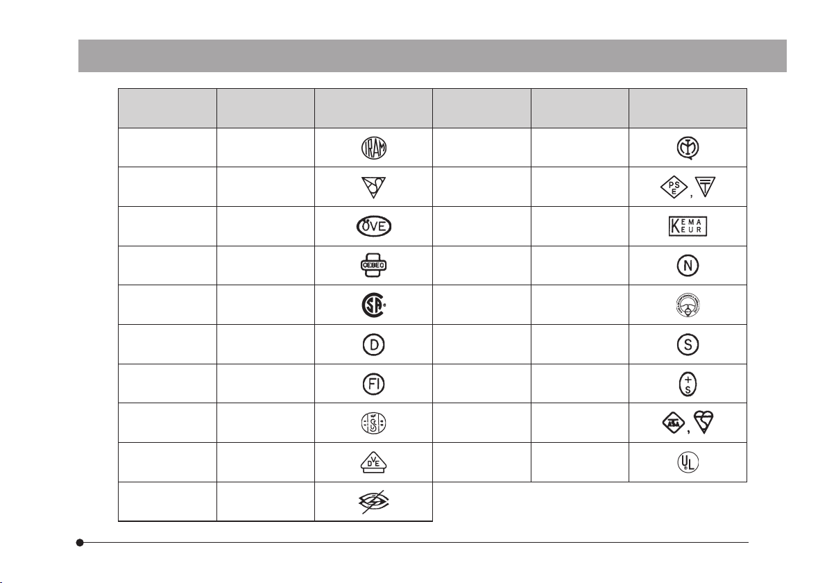
Table 1 Certified Cord
A power cord should be certified by one of the agencies listed in Table 1 , or comprised of cordage marked with
an agency marking per Table 1 or marked per Table 2. The fittings are to be marked with at least one of the
agencies listed in Table 1. In case you are unable to buy locally the power cord which is approved by one of
the agencies mentioned in Table 1, please use replacements approved by any other equivalent and authorized
agencies in your country.
Page 29
DP26
Country Agency
Argentina
Australia SAA Japan
Austria ÖVE Netherlands KEMA
Belgium CEBEC Norway NEMKO
Canada CSA Spain AEE
Denmark DEMKO Sweden SEMKO
Finland FEI Switzerland SEV
France UTE
Germany VDE U.S.A. UL
IRAM Italy IMQ
Certification
Mark
Country Agency
JET, JQA, TÜV,
UL Japan/METI
United
Kingdom
ASTA
BSI
Certification
Mark
Ireland NSAI
26
Page 30

Table 2 HAR Flexible Cord
APPROVAL ORGANIZATIONS AND CORDAGE HARMONIZATION MARKING METHODS
27
Printed or Embossed Harmoni-
Approval Organization
Comite Electrotechnique Belge
(CEBEC)
Verband Deutscher Elektrotechniker
(VDE) e.V. Prüstelle
Union Technique de I´Electricite´
(UTE)
Instituto Italiano del Marchio di
Qualita´ (IMQ)
British Approvals Service for Electric
Cables (BASEC)
N.V. KEMA KEMA-KEUR <HAR>
SEMKO AB Svenska Elektriska
Materielkontrollanstalter
zation Marking (May be located
on jacket or insulation of internal wiring)
CEBEC <HAR>
<VDE> <HAR>
USE <HAR>
IEMMEQU <HAR>
BASEC <HAR>
SEMKO <HAR>
Alternative Marking Utilizing Black-Red-Yellow Thread
(Length of color section in mm)
Black Red Yellow
10 30 10
30 10 10
30 10 30
10 30 50
10 10 30
10 30 30
10 10 50
Page 31

DP26
Österreichischer Verband für
Elektrotechnik (ÖVE)
Danmarks Elektriske Materialkontroll
(DEMKO)
National Standards Authority of
Ireland (NSAI)
Norges Elektriske Materiellkontroll
(NEMKO)
Asociacion Electrotecnica Y
Electronica Espanola (AEE)
Hellenic Organization for
Standardization (ELOT)
Instituto Portages da Qualidade
(IPQ)
Schweizerischer Elektro
Technischer Verein (SEV)
<ÖVE> <HAR>
<DEMKO> <HAR>
<NSAI> <HAR>
NEMKO <HAR>
<UNED> <HAR>
ELOT <HAR>
np <HAR>
SEV <HAR>
Elektriska Inspektoratet SETI <HAR>
Underwriters Laboratories Inc. (UL) SV, SVT, SJ or SJT, 3 X 18AWG
Canadian Standards Association (CSA) SV, SVT, SJ or SJT, 3 X 18AWG
30 10 50
30 10 30
30 30 50
10 10 70
30 10 70
30 30 70
10 10 90
10 30 90
10 30 90
28
Page 32

MEMO
Page 33

MEMO
Page 34

MEMO
Page 35

Page 36

2011 06-02
 Loading...