

Page 1

INSTRUCTIONS
DP21
MICROSCOPE DIGITAL CAMERA
This instruction manual is for the Olympus Microscope Digital Camera Model DP21.
To ensure the safety, obtain optimum performance and familiarize yourself fully with the use of this
camera, we recommend that you study this manual thoroughly before operating the camera.
Retain this instruction manual in an easily accessible place near the work desk for future reference.
A X 7 9 3 1
Page 2
Notations Used in This Manual
This system is used either in a standalone (SAL) or PC-connection (PC) configuration.
Each page of this manual carries one of notations “Common,” “SAL” and “PC” on the top right to indicate the applicable
configuration of the descriptions in it. Please read the pages applicable to your configuration.
1. Important (Common) p.1 to p.4
This chapter describes the cautions related to the safety and operation of the system.
2. Standalone System (SAL) p.5 to p.66
This chapter describes the operation of the configuration in which the camera head is connected to
the control box.
3. PC Connection System (PC) p.67 to p.81
This chapter describes the operation of the configuration in which the camera head is connected to
a desktop or laptop PC.
4. General (Common) p.82 to p.87
This chapter describes the specifications and troubleshooting information.
This device complies with the requirements of both directive 2004/108/EC concerning electromagnetic compatibility and directive 2006/95/EC concerning low voltage.
In accordance with European Directive 2002/96/EC on Waste Electrical and Electronic Equipment,
this symbol indicates that the product must not be disposed of as unsorted municipal waste, but
should be collected separately.
Refer to your local Olympus distributor in EU for return and/or collection systems available in your
country.
NOTE: This equipment has been tested and found to comply with the limits for a Class A digital device,
pursuant to Part 15 of the FCC Rules. These limits are designed to provide reasonable protection
against harmful interference when the equipment is operated in a commercial environment. This
equipment generates, uses, and can radiate radio frequency energy and, if not installed and used in
accordance with the instruction manual, may cause harmful interference to radio communications.
Operation of this equipment in a residential area is likely to cause harmful interference in which case
the user will be required to correct the interference at his own expense.
FCC WARNING: Changes or modifications not expressly approved by the party responsible for compliance
could void the user’s authority to operate the equipment.
CALIFORNIA USA ONLY
This control box uses a Lithium Battery which contains Perchlorate Material - special handling may apply,
See www.dtsc.ca.gov/hazardouswaste/perchlorate.
Page 3

CONTENTS
1 IMPORTANT (Common)
1-1 Safety Precautions ................................................................................................................................................................................. 1
1-2 Conformity of the System ............................................................................................................................................................ 2
1-3 Getting Ready ............................................................................................................................................................................................... 3
1-4 Maintenance and Storage .......................................................................................................................................................... 3
1-5 Caution ................................................................................................................................................................................................................... 4
2 Standalone System (SAL)
2-1 Operating Precautions .............................................................................................................................................................. 5,6
2-2 System Chart ................................................................................................................................................................................................. 7
2-3 Nomenclature..................................................................................................................................................................................... 8-11
2-3-1 Hardware controls.............................................................................................................................................................................................................. 8,9
2-3-2 MENU / INFO display.............................................................................................................................................................................................. 10,11
2-4 Installation ............................................................................................................................................................................................. 11- 16
2-5 Basic Image Recording Procedure ................................................................................................................. 17-24
2-5-1 Operation flow ............................................................................................................................................................................................................... 17-24
1 Turning Power ON/OFF...................................................................................................................................................................................................... 18
2 Initial Setting ....................................................................................................................................................................................................................................... 19
3 Selecting the Mode ................................................................................................................................................................................................................ 20
4 Viewing/Hiding the INFO Display....................................................................................................................................................................... 20
5 Viewing/Controlling the MENU Display .................................................................................................................................................... 21
6 Setting the Live Resolution Default: 1600 x 1200 ......................................................................................................... 22
7 OTWB (One-Touch White Balance) ................................................................................................................................................................. 22
8 Recording Still Images ...................................................................................................................................................................................................... 23
9 Recording Movies ..................................................................................................................................................................................................................... 24
1-4
5-66
2-6 Recording Function Setting/Operation (REC)................................................................................. 25-48
2-6-1 Operation using the hand switch ................................................................................................................................................... 25-48
1 Available Functions................................................................................................................................................................................................................. 25
2 Exposure Adjustment .......................................................................................................................................................................................................... 26
3 SPOT Metering Setting ...................................................................................................................................................................................................... 26
4 AE Lock Setting ............................................................................................................................................................................................................................ 27
5 Zooming/Scrolling ................................................................................................................................................................................................................... 27
6 Composite Button Operations ............................................................................................................................................................................... 28
2-6-2 Operation using the MENU display.............................................................................................................................................. 29-33
1 Viewing the MENU Display.......................................................................................................................................................................................... 29
2 Image Quality Mode Setting Default: HQ..................................................................................................................................... 30
3 ISO Speed Setting Default: 100.................................................................................................................................................................. 30
4 Sharpness Setting Default: NORMAL ................................................................................................................................................ 30
5 Save Folder Setting Default: AUTO .............................................................................................................................................. 31,32
6 White Balance (WB) Mode Setting Default: AUTO ......................................................................................................... 33
7 Folder and File Names ...................................................................................................................................................................................................... 33
2-6-3 Applied operations................................................................................................................................................................................................ 34-48
1 Manual recording ...................................................................................................................................................................................................................... 34
2 REC VIEW Setting Default: 5 sec. ............................................................................................................................................................ 34
3 Image Color Setting Default: COLOR-1 .......................................................................................................................................... 34
4 Scale Display Setting Default: OFF ........................................................................................................................................ 35-37
Page 4

5 Scale Display Range Setting Default: LIVE & SNAP .................................................................................................. 37
6 Image Orientation Setting Default: Erect ...................................................................................................................................... 37
7 Focusing indicator Setting Default: OFF ........................................................................................................................... 37,38
8 AE Area Display Setting Default: OFF ............................................................................................................................................... 39
9 Measurement Functions .................................................................................................................................................................................... 39-48
10 Cross lines display .................................................................................................................................................................................................................. 48
2-7 Playback Function Setting/Operation (PLAY) ................................................................................... 49-52
1 Selecting the Mode ................................................................................................................................................................................................................ 49
2 Viewing/Hiding the INFO Display....................................................................................................................................................................... 49
3 Selecting the Played Image ....................................................................................................................................................................................... 49
4 Selecting the Played Movie ........................................................................................................................................................................................ 50
5 Zooming/Scrolling ................................................................................................................................................................................................................... 50
6 Viewing the Index Display ............................................................................................................................................................................................. 51
7 Erasing an Image ...................................................................................................................................................................................................................... 52
8 Protecting an Image .............................................................................................................................................................................................................. 52
9 Measuring a Played Image ......................................................................................................................................................................................... 52
2-8 MENU Display Functions .............................................................................................................................................. 53-59
1 Media Setup ...................................................................................................................................................................................................................................... 53
2 Date/Time Setting ..................................................................................................................................................................................................................... 53
3 Reset ............................................................................................................................................................................................................................................................ 54
4 Recorded Folder Setting ................................................................................................................................................................................................. 54
5 Options ........................................................................................................................................................................................................................................... 54,55
6 Maintenance Setting ............................................................................................................................................................................................... 55-58
7 Operation Using Mouse and Keyboard.................................................................................................................................................... 59
2-9 Functions Interlocked with Microscope Operations............................................................. 60-66
2-9-1 System chart................................................................................................................................................................................................................................ 60
2-9-2 Connection ........................................................................................................................................................................................................................ 61-63
2-9-3 Operation............................................................................................................................................................................................................................. 64-66
3 PC Connection System (PC)
3-1 Operating Precautions ................................................................................................................................................................ 67
3-2 System Chart ............................................................................................................................................................................................. 68
3-3 Nomenclature........................................................................................................................................................................................... 69
3-4 Installation ............................................................................................................................................................................................ 70,71
3-5 DP2-TWAIN Software Installation........................................................................................................................ 72-78
3-6 Image Recording Procedure Using DP21-TWAIN ................................................................................. 79
3-7 Displayed Windows of DP2-TWAIN ........................................................................................................................... 80
3-8 DP2-TWAIN Software Uninstallation ......................................................................................................................... 81
4 GENERAL (Common)
4-1 Warning Messages .......................................................................................................................................................................... 82
4-2 Specifications ................................................................................................................................................................................. 83,84
4-3 Troubleshooting Guide .................................................................................................................................................... 85-87
4-4 Index ............................................................................................................................................................................................................ 88,89
67-81
82-87
PROPER SELECTION OF THE POWER SUPPLY CORD.................................................................... 90,91
Page 5
1
IMPORTANT (COMMON)
The DP21 microscope digital camera is designed to be connected to a camera adapter mounted on an
Olympus UIS2/UIS series microscope for use in recording of microscopic magnified image of the optical
microscope.
When the DP21 is used with a camera adapter from other manufacturer than Olympus, the optical performance may not be manifested fully.
1-1 Safety Precautions
1. Before connecting or disconnecting a connection cable or power cord, make sure that the main switch of the control box
is set to OFF.
When connecting the cable or power cord, push in the connector all the way before pressing the main switch to ON.
CAUTION
To avoid electric shock or equipment failure, never connect or disconnect a cable while the main switch is
set to ON.
2. Always use the AC adapter provided by Olympus.
Using a similar but non-Olympus AC adapter does not only allow the camera to manifest its full performance but may
also cause an equipment failure as well as a burn or fire hazard due to abnormal heating. Never use such an AC adapter.
3. The cords and cables are vulnerable to bend or twist. Do not apply excessive force to them.
Also distribute the cords and cables away from a heat-generating part such as the lamp housing of the microscope.
4. To prevent the microscope from toppling down, avoid using microscope attachments that may make the total height of
the microscope above 1 meter when they are attached.
5. The AC adapter, camera head, control box and USB memory generate heat after they have been used for a long period
of time.
To avoid moderate temperature burn, do not leave these parts in extended contact with your skin.
6. Connect the power cord correctly and ensure that the grounding terminals of the power supply and wall outlet are
properly connected. If the equipment is not grounded/earthed, Olympus can no longer warrant the electrical safety
performance of the equipment.
Common
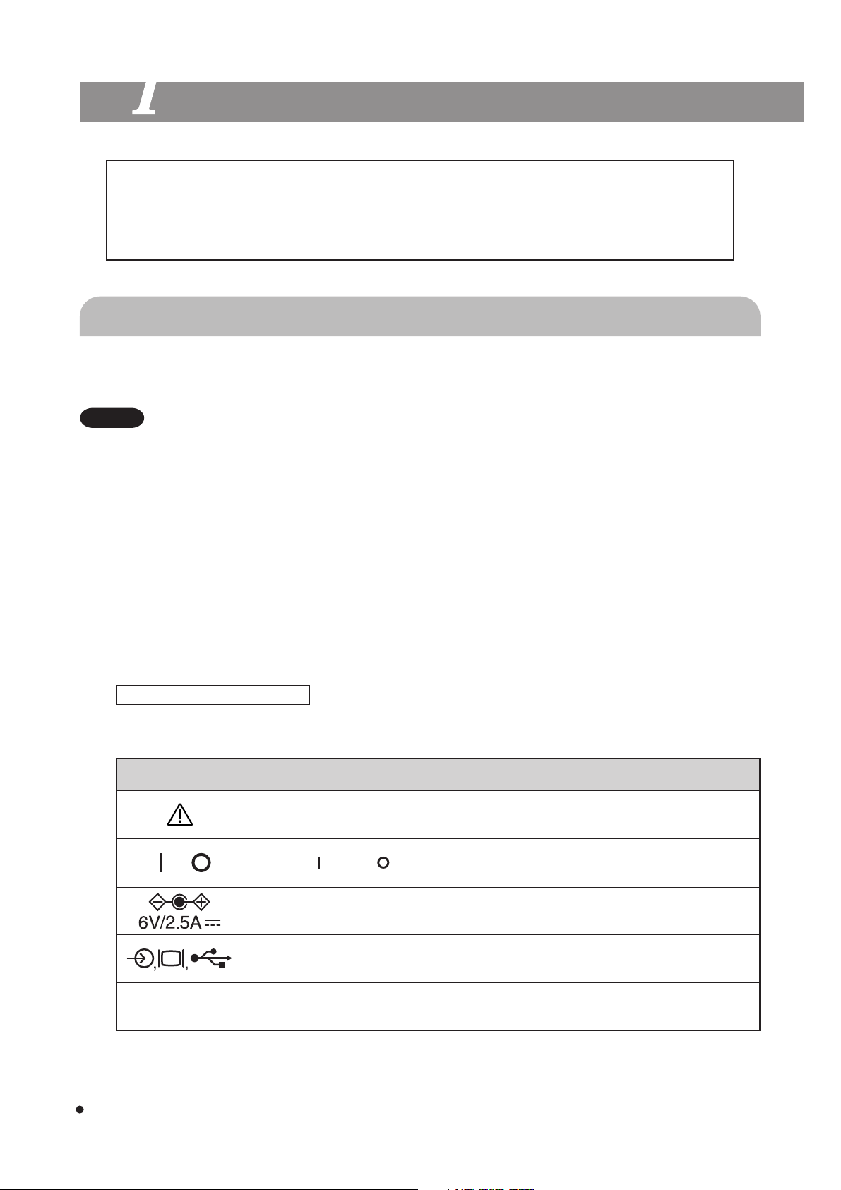
Safety and Operation Symbols
The following symbols are found on the control box, hand switch and camera head. Study the meaning of the symbols
and always use the equipment in the safest possible manner.
Symbol Explanation
Before use, carefully read the instruction manual. Improper use could result in personal injury
to the user and/or damage to the equipment.
,
1394
Indicates “ ” (ON) or “ ” (OFF) of the main switch.
Use the specified AC adapter (6 V, 2.5 A DC)
Symbols representing an input connector, display, and USB connector respectively.
Symbol of camera cable (1394) connector.
1
Page 6

1-2 Conformity of the System
Restrictions in Use
1. The standard TV adapters are the U-TV1X-2 and U-TV0.5XC-3.
The U-TV0.25xC, U-TV0.35xC (or a TV adapter with magnification below 0.5X), U-TV0.5XC and GX-TV0.5XC-DP cannot be
used because of optical performance problems.
2. When the DP21 is connected to the rear port of the U-DPT or U-MPH, the peripheral part of the recorded image may be
deteriorated due to the optical performance of the U-DPT or U-MPH.
3. When two or more intermediate attachments are used, the peripheral part of the image may become dark or obscured
depending on the observation tube and objective in use.
4. When a fluorescent lamp illumination or an illumination stand of the SZX/SZX2 series is used, the image may flicker.
5. When a non-Olympus microscope or a commercially available C-mount lens is used, problems due to the optical
adaptability such as shading may be observed. If a commercially available C-mount lens is used, the thread projection
and lens projection from the C-mount body attaching section should be no more than 4.5 mm.
6. When the specimen has a low contrast (near transparent) or high reflectance (mirror status) and the aperture iris diaphragm is stopped down near the smallest aperture, spot flare may be noticeable.
7. When the edge of a non-transmitting object is observed under the STM6 transmitted illumination, flare may be noticeable
due to the difference in brightness between the transmitted sections (over-exposure) and non-transmitting section (underexposure).
To reduce the flare, set a lower exposure using the exposure adjustment function or setting the exposure manually.
(Details of STM6 combination)
Edge observation using the MM6-OB3X/5X/10X objective in combination with the MM6C-VL/MM6-ETR
8. When the SZX16 is combined, the peripheral brightness may become insufficient with a zoom ratio of no more than 10x.
9. The image of dark specimens under reflected light or in the darkfield (specimens that need exposure of 1/2 sec. or more
at ISO 100 equivalent) cannot be recorded.
10. Specimens with a distribution that is not suitable for center averaged metering require spot metering or exposure adjustment.
11. When electronic zoom is used for magnification display during focusing, the image may become noticeably coarse with
certain samples.
12. The live image frame rate of 15 fps is possible when the exposure time is no more than 1/15 sec.
13. When the scale recording function or measurement function is used, the image capturing time becomes longer than
usual.
14. The trackability of auto white balance control deteriorates when the specimen contains little white area.
15. The measurement results are simply superimposed on the image and no text file or like is created.
16. The DP21 can handle files of the FAT and FAT32 formats only, and it is not compatible with other file formats. When using
a recording medium of an incompatible format, it is required to convert the format into FAT or FAT32 using a PC.
17. It is not possible to use a special USB memory adopting the security or password lock function.
18. To prevent destruction of the recorded image (data), never perform the following action during recording of a still image
or movie;
· turning power OFF;
· disconnecting the AC adapter;
· disconnecting the recording medium such as the USB memory or LAN cable.
2
Operating Environment
Temperature: 5 to 35°C. Humidity: 20% to 85% (without condensation).
Recommended Monitor Specifications
A monitor with the 800 x 600 or larger full-color display capability (the factory setting is WUXGA 1920 x 1200).
Compliance to the VESA DDC2B standard.
Page 7

1-3 Getting Ready
1. The camera head uses precision components. Handle it with care and avoid subjecting it to a sudden or severe impact.
2. The image displayed on the monitor may be affected when it is used near equipment generating strong electromagnetic
waves. To avoid interference during operation, keep the system far from any source of electromagnetic waves.
3. Do not use the camera in areas where it may be subjected to direct sunlight, high temperature and humidity, dust or
vibrations. (For the operating environment conditions, see “SPECIFICATIONS” on page 83.)
1-4 Maintenance and Storage
1. To clean the lenses and other glass components, simply blow dirt away using a commercially available blower and wipe
gently using a piece of cleaning paper (or clean gauze).
If a lens is stained with fingerprints or oil smudges, wipe it with gauze slightly moistened with commercially available
absolute alcohol.
CAUTION
Since the absolute alcohol is highly flammable, it must be handled carefully. To prevent fire ignition, be sure
to keep it away from open flames or potential sources of electric sparks -- for example, electrical equipment
that is being switched on or off.
Also remember to always use these chemicals only in a well-ventilated room.
2. Parts other than the glass components should be cleaned by wiping with a clean cloth. Do not use organic solvents to
remove major stains. Use a soft cloth slightly moistened with a neutral detergent solution.
3. Do not disassemble any part of the camera as this could result in malfunction or reduced performance.
4. When the system is not used, store it with the dust cover. Before storage, ensure that the main switches of the DP21’s
control box and the microscope are set to OFF and that the lamp housing is cool enough.
5. When smoking the room for cleaning, etc., move the DP21 to a place not exposed to smoke.
6. Care is required against condensation as this may sometimes cause malfunction. Condensation is the phenomenon in
which the vapor in the air is condensed into water drops, which attach to the surface of a metallic plate, etc. It often occurs
when the ambient temperature changes suddenly, for example when a camera is brought from cold outdoors into warm
indoors.
Common
3
Page 8

1-5 Caution
If the equipment is used in a manner not specified by this manual, the safety of the user may be imperiled. In addition, the
equipment may also be damaged. Always use the equipment as outlined in this instruction manual.
The following symbols are used to set off text in this instruction manual.
CAUTION
} : Indicates commentary (for ease of operation and maintenance).
The recorded image data may be lost (destroyed) in the following cases. Note that Olympus will not
assume any liabilities for the loss (destruction) of recorded data.
The image data may also be destroyed by an unexpected cause. It is recommended to back up the
data periodically.
· When the user or a third party used the USB memory in a wrong way.
· When the user or a third party services or repairs the equipment.
· When the USB memory is affected by static electricity or electromagnetic noise.
· When the USB memory is unplugged, the main switch is set to OFF, the AC adapter is disconnected
or the power cord is unplugged during recording or erasure (formatting) of the USB memory.
· When the equipment fails.
: Indicates a potentially hazardous situation which, if not avoided, may result in minor or
moderate injury or damage to the equipment or other property. It may also be used to
alert against unsafe practices.
Caution on Image Data Storage
Note on Disposal
Be sure to observe your local regulations and rules when disposing of this product. Special care is required for the control
box because it incorporates a lithium manganese coin battery (CR2032). If you have any doubt, please consult Olympus.
4
Page 9

SAL System
STANDALONE SYSTEM (SAL)
Read this chapter if you use the camera head by connecting it to the control box.
2-1 Operating Precautions
System Compatibility
· Only the following USB devices function when connected to the control box, etc.
Connectable USB devices: USB removable media such as a USB memory
USB mouse
USB keyboard
· Even when one of the USB devices is used, it cannot be connected if it needs a special driver or the Explorer function
of the PC for operation.
· When a USB device with current consumption above 200 mA (including a USB memory, mouse or keyboard) is
connected, it may not function due to insufficient power supply from the hand switch.
· The network connection requirements are as follows.
Applicable PC: DOS/V AT compatible machine
Applicable OS: Windows XP Professional/Vista Business (32-bit)/Vista Ultimate (32-bit)
Standards: IEEE802.3 (10BASE-T Ethernet),
IEEE802.3u (100BASE-TX Fast Ethernet) compliant
Applicable protocol: TCP/IP (Incompatible with IPv6)
Connector: RJ-45 type 8-pole connector
Transmission rate: 10 Mbps (10BASE-T Ethernet)/100 Mbps (100BASE-TX Fast Ethernet)
Even when the connection requirements above are met, connection and operation in any network environment is not
guaranteed.
Computer Virus Note
As a countermeasure against computer viruses, the DP21 is set to inhibit write of foreign files in the system domain.
Nevertheless, it is not capable of preventing infection by computer viruses that are evolving day by day. To prevent
penetration of computer viruses in the DP21, it is also recommended to take the following countermeasures.
· Perform virus check on the removal medium, such as a USB memory, before connecting it to the DP21. (The DP21
does not have the virus check function. Use your PC for virus checking.)
· Ensure that the network and PC to which the DP21 is connected are free of computer viruses.
· Should infection of a computer virus occur or be suspected, turn the control box of the DP21 OFF and unplug its
power cord. This clears the RAM and deletes any foreign files.
· If malfunction or a symptom of infection still persists after the above measure, please consult Olympus.
Olympus will not assume any liabilities for a malfunction of the DP21 due to computer viruses as well as any trouble or
damage of the user’s PC or network incurred due to computer viruses.
5
Page 10

Battery Life
The DP21’s control box incorporates a lithium ion coin battery (CR2032) for backing up the calendar function. The service
life of the battery is 1 to 6 years (it is widely variable because the battery power consumption is reduced during operation
connecting the AC adapter to the control box). The camera can be used even after the battery life has expired, but the
calendar is reset every time the AC adapter is unplugged.
For the battery replacement, contact Olympus.
Control Box Fan
The control box has a ventilation fan. Be careful not to block the ventilation opening. To ensure sufficient ventilation, install
the control box at a distance of 10 cm or more from an obstacle such as a wall.
Blocking the ventilation opening will result in malfunction or damage. Additional care is also required against penetration
of a foreign object through the ventilation opening because this may result in the fan damage. The rotation speed of the
control box fan varies depending on the system internal temperature. As a result, the fan noise may increase in the
following cases but this is not malfunction.
· When the ambient temperature is high in summer, etc.
· When the system temperature is high after long hours of use, etc.
· About 10 seconds after startup.
6
Page 11
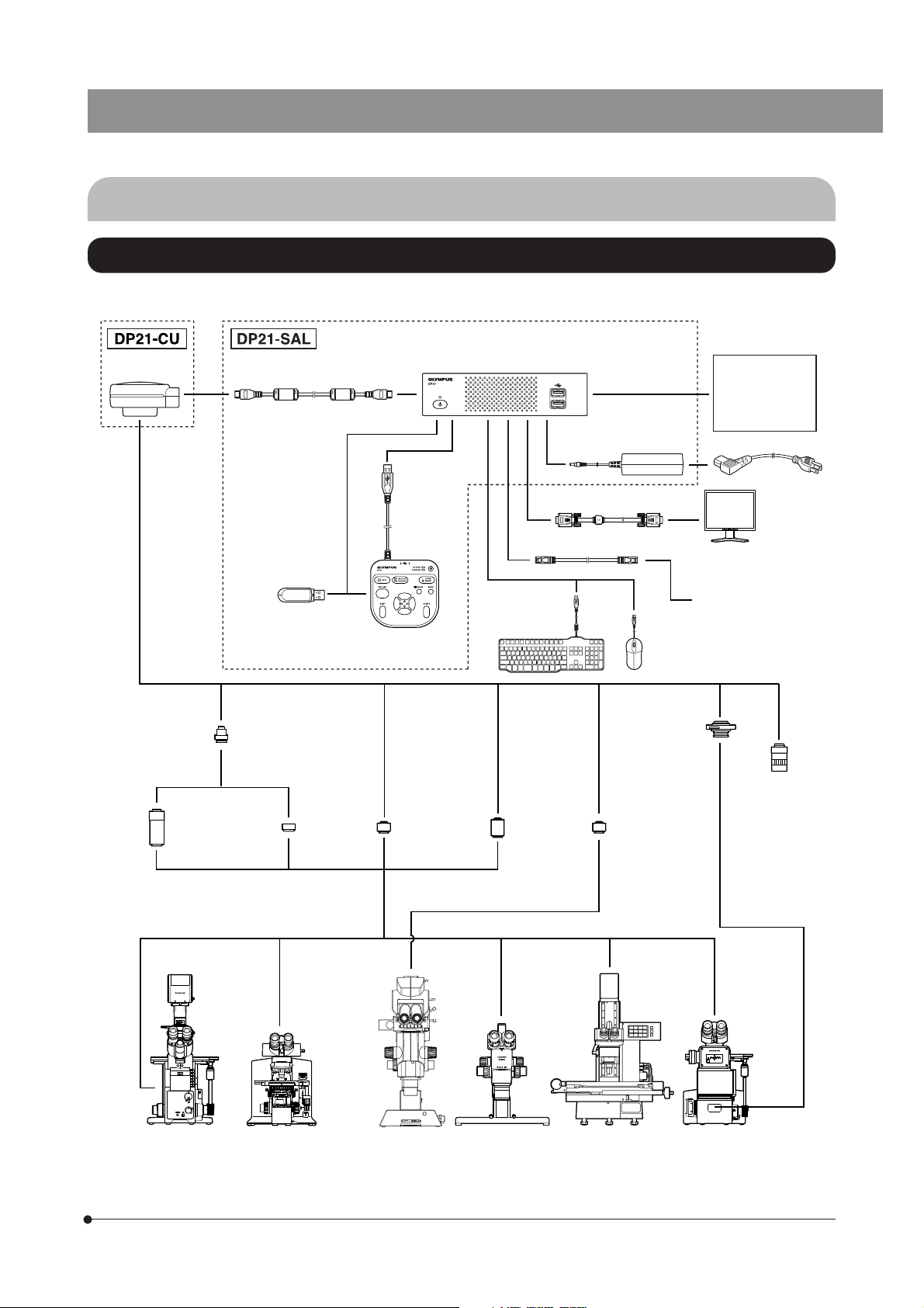
2-2 System Chart
SAL (Standalone) System
}If you use a PC (PC connection) system, read from page 67.
SAL System
Camera head
D21-CU
U-TV0.5X
Camera
Adapter
0.5X
Camera cable
USB memory
U-CMAD3
C-mount
Camera
Adapter
U-TV1X-2
Camera
Adapter
1X
Hand Switch
D21-HS
U-TV0.5XC-3
C-mount
Camera
Adapter
Control box
D21-CB
Keyboard
U-TV0.63XC
C-mount
Camera
Adapter
Display cable
LAN cable
AC adapter
Mouse
GX-TV0.5XC
C-mount
Camera
Adapter
GX-TV0.7XC
C-mount
Camera
Adapter
MVX-TV0.63XC
C-mount
Camera
Adapter
MVX-TV1XC
C-mount
Camera
Adapter
Control box for
coded units
· U-CBS
· U-CBM
· BX3-CBH
Power cord
Monitor display
To network
C-mount
lens
AX80/AX70
IX81/IX71/IX51
Inverted
Microscope
BX63/BX61
BX53/BX51
BX46/BX43/BX41
CX41/CX31
MX80/MX50/MX40
MX61L/MX61/MX51
Erected Microscope
MVX10
SZX16/SZX10
SZX12/SZX9
SZX7/SZ61
Stereo
Microscope
STM6
Measuring
Microscope
GX71/GX51
Inverted
Metallurgical
Microscope
(Note 1) Certain microscopes are also applicable even when they are not mentioned above. Please consult Olympus for
details.
(Note 2) Image color setup matching the microscope is required for faithful color reproduction (see page 34 for details).
7
Page 12
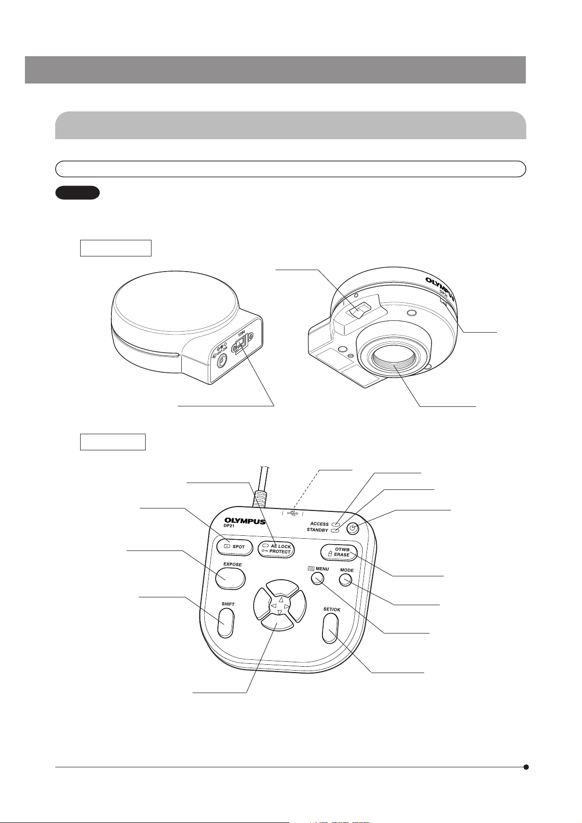
2-3 Nomenclature
2-3-1 Hardware controls
CAUTION
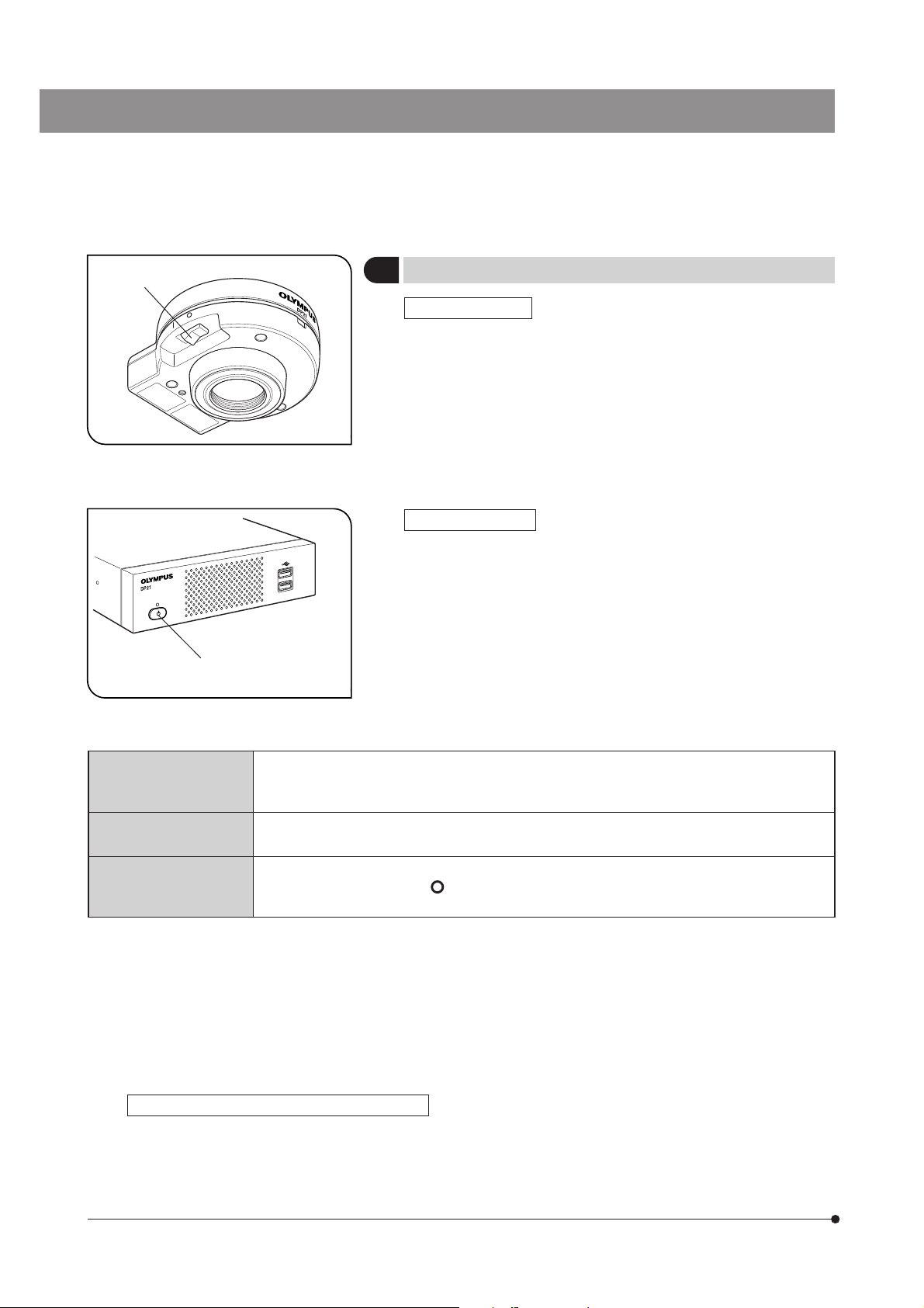
Camera Head
Hand Switch
Any equipment connected to the camera head should be an Olympus-designated product or a product in
compliance with the requirements of IEC60950 or CISPR22/24. If equipment other than these products is
connected, Olympus cannot guarantee any performance of the camera.
Main switch
Pilot LED
Camera cable connector
AE LOCK button
(PROTECT button)
USB port
ACCESS LED
STANDBY LED
C-mount thread
8
SPOT button
EXPOSE button
SHIFT button
Standby switch
OTWB button
(ERASE button)
MODE button
MENU button
SET/OK button
Cursor buttons
Page 13
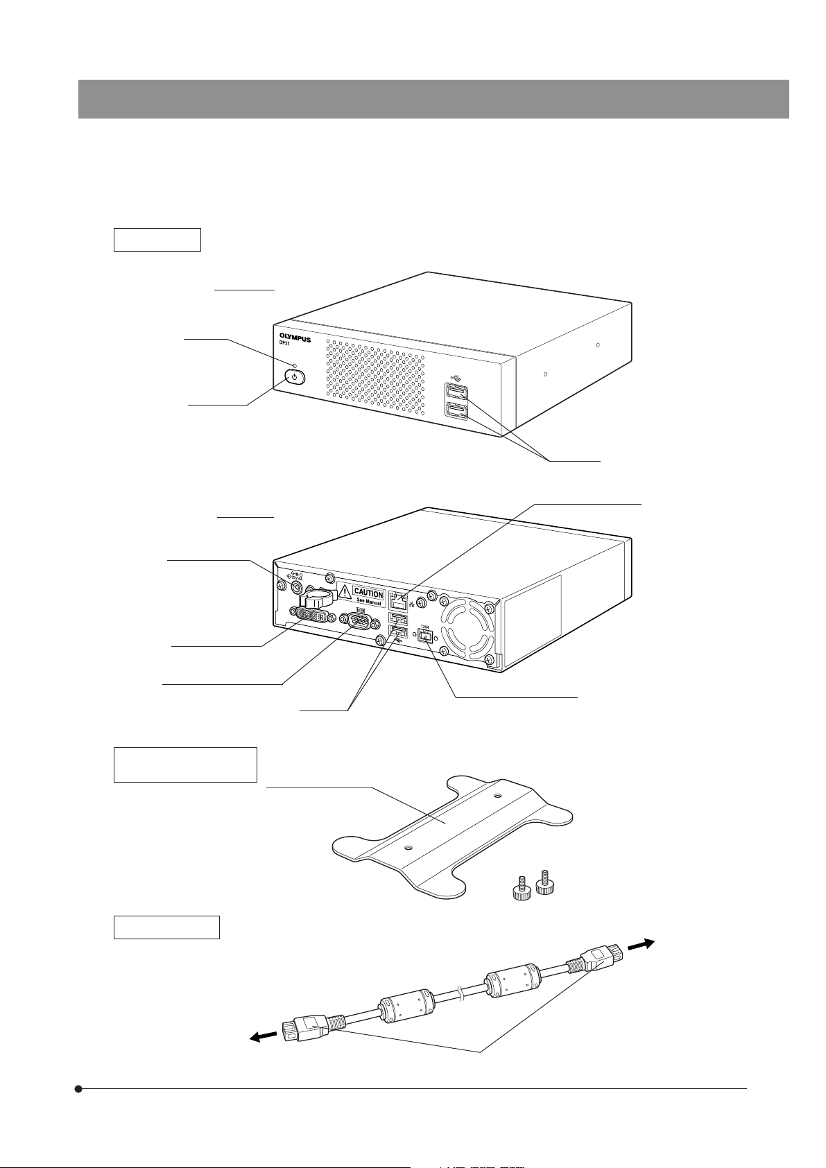
Control Box
Pilot LED
SAL System
Front view
Main switch
USB ports
Rear view
DC IN connector
Display connector
DVI-I/-D/-A
RS232C connector
For connection of the
control box (U-CBS, etc.)
Stabilizer for Vertical
Installation
LAN cable connector
Camera cable connector
USB ports
Stabilizer
With 2 clamp screws
Camera Cable
Camera head
Control box
1394b connector (9-pin)
9
Page 14
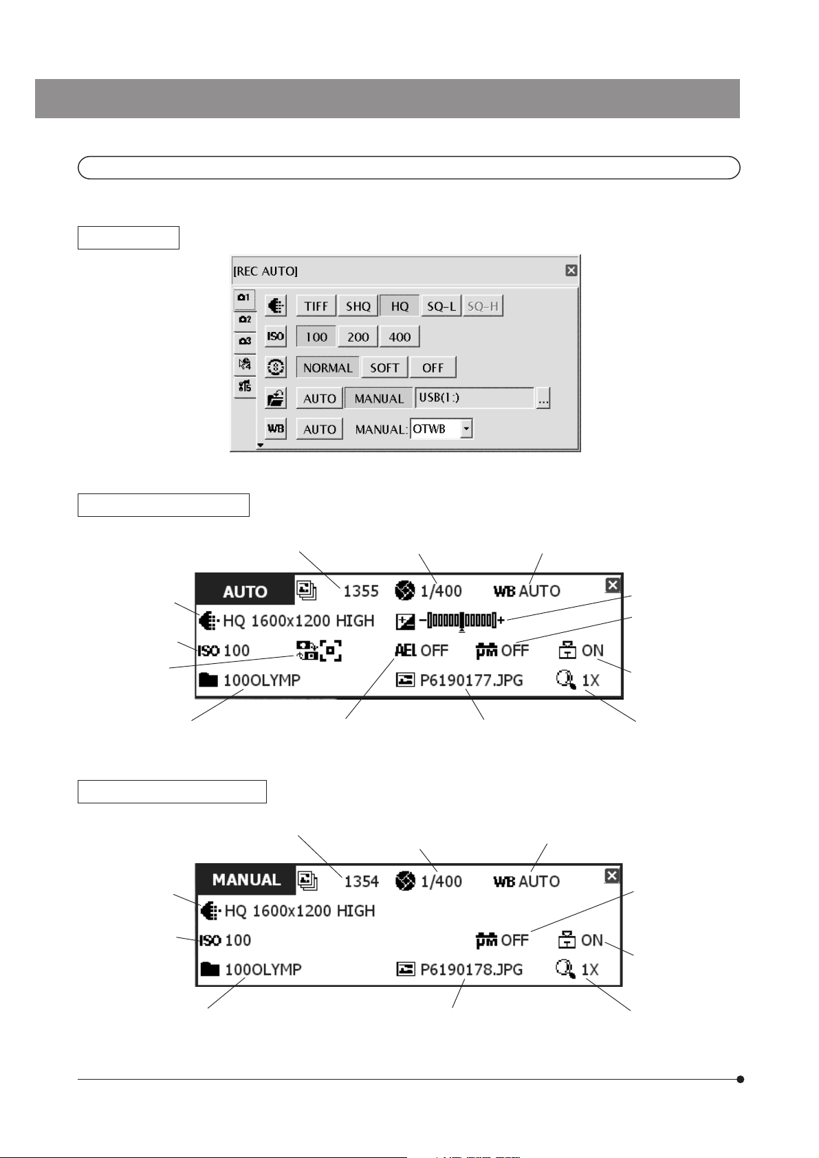
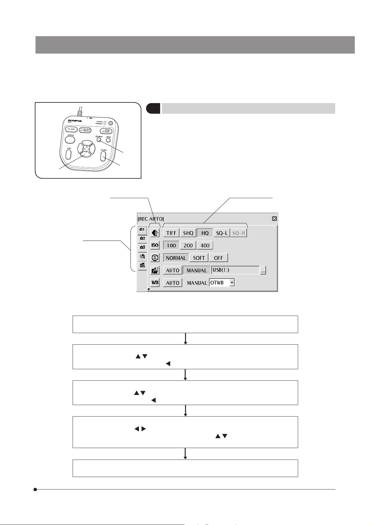
2-3-2 MENU / INFO display
MENU display
INFO display (REC AUTO)
No. of remaining image
(p. 23)
Image
quality (p. 30)
ISO speed (p. 30)
Metering
area (p. 26)
Folder name (p. 31)
INFO display (REC MANUAL)
No. of remaining image
(p. 23)
Image
quality (p. 30)
ISO speed (p. 30)
Exposure
time
Exposure
time (p. 34)
White balance (p. 33)
Exposure
adjustment (p. 26)
Scale setting
(p. 35)
Scale display area
(p. 37)
Zoom (p. 27)File name (p. 33)AE lock (p. 27)
White balance (p. 33)
Scale setting
(p. 35)
Scale display area
(p. 37)
10
Zoom (p. 27)File name (p. 33)Folder name (p. 31)
Page 15
SAL System
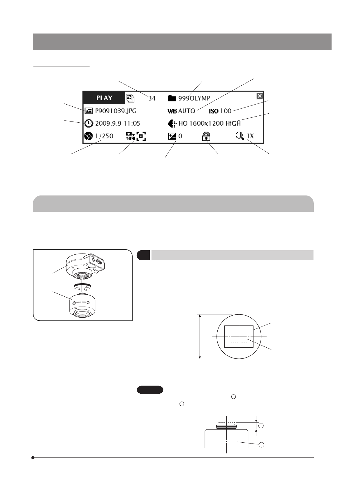
INFO display (PLAY)
File name (p. 33)
Date / Time
(p. 53)
Exposure time
(p. 34)
If the save destination is set to a network location, the INFO display may sometimes not show the number of
remaining image.
Image No.
Metering area
(p. 26)
adjustment (p. 26)
Recorded folder
name (p. 54)
White balance (p. 33)
ISO speed (p. 30)
Image quality
(p. 30)
Zoom (p. 27)Protect (p. 52)Exposure
2-4 Installation
This section pertains only to the installation of the DP21 microscope digital camera.
For the installation of the combined microscope, camera adapter, etc., refer to their instruction manuals and install carefully.
2
1
Fig. 1
Installing the Camera Head
1
Screw in the U-TV0.5XC-3 C-mount camera adapter @ into the mount
thread at the bottom of the camera head ². If you use a different Cmount TV adapter, follow its instruction manual.
· As the photographed field is as shown below, use a camera adapter
having magnification of 0.5X to 1X. (If a 0.35X camera adapter is used, the
peripheral part of the image will be obscured.)
0.5X (FN 17.6)
Field number
22
1X (FN 8.8)
· If a C-mount TV adapter from other manufacturer than Olympus is used,
the optical performance of the system may not be manifested fully.
CAUTION
Be careful in using other manufacturer’s C-mount camera
adapter or C-mount lens
b . Otherwise, the threaded section will hit the inside of the
camera head and cause damage to it.
a
having a thread length over 4.5 mm
(Fig. 1)
b
a
11
Page 16
1
2
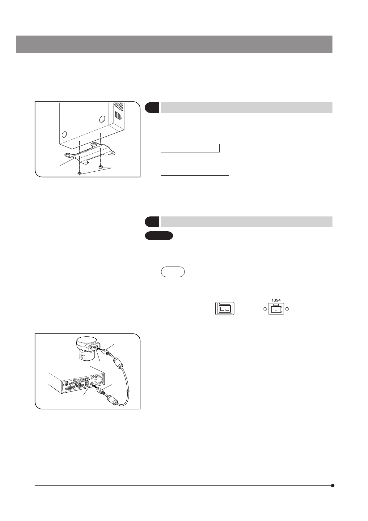
Installing the Control Box
2
}The control box can be installed either horizontally or vertically.
}Do not place a heavy object weighing over 10 kg or an object that would
make the installation unstable on the control box.
Horizontal installation
Place the control box on the desktop so that its rubber feet contact the
desktop surface.
(Fig. 2)
Fig. 2
2
1
Vertical installation (Fig. 2)
Attach the stabilizer @ provided with the control box on the side of the
control box using the provided screws ².
Always use the provided stabilizer for vertical installation.
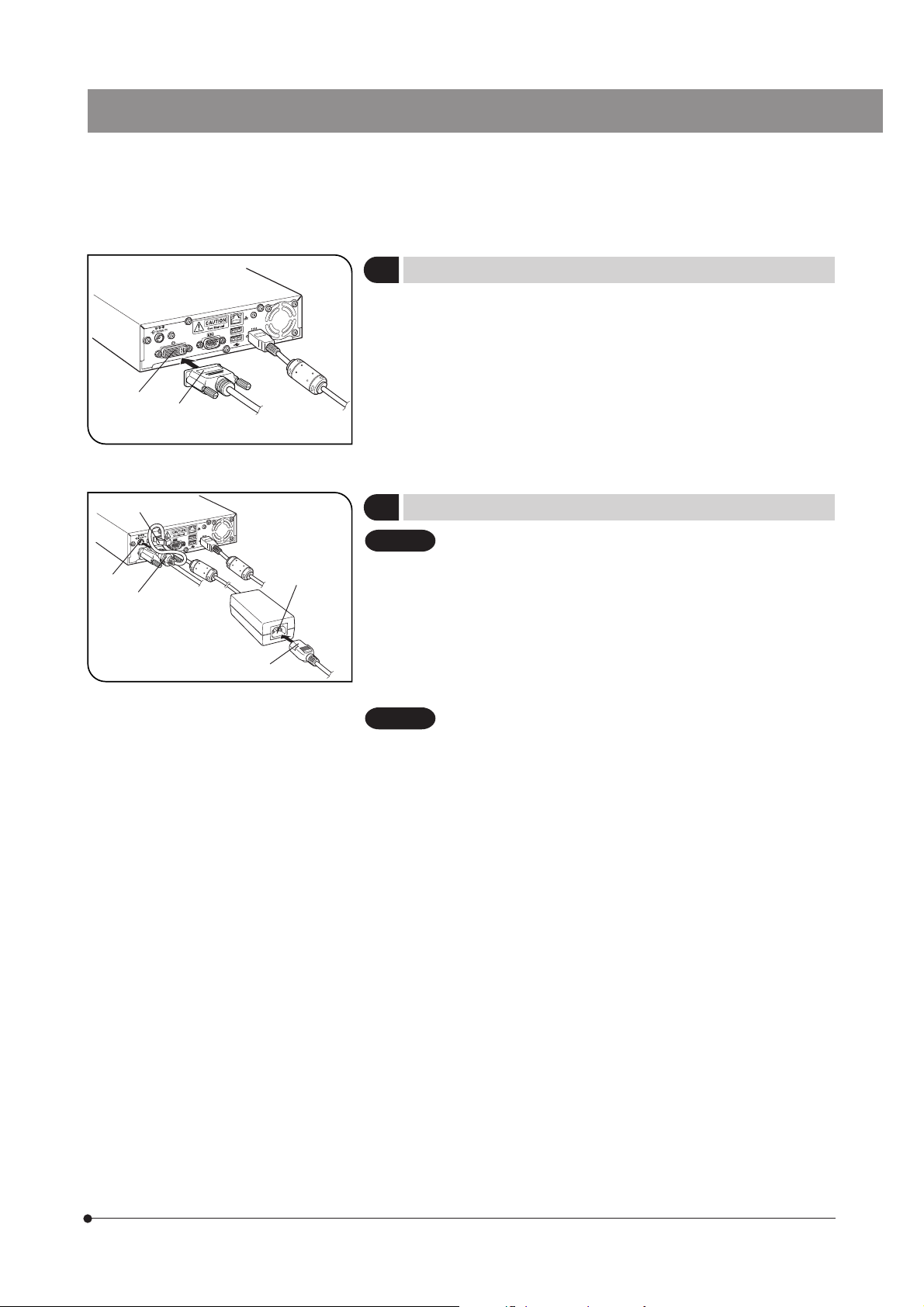
Connecting the Camera Cable
3
CAUTION
· The cords and cables are vulnerable to bend or twist. Do not
apply excessive force to them.
· Be sure to switch off the control box before proceeding to the
connection.
NOTE
1. Insert the connector @ on one end of the camera cable into the connector ² on the camera head.
2. Insert the connector ³ on the other end of the camera cable into the
connector | on the control box.
When connecting the cable, insert the connector plug in
the proper direction.
(Example: Camera cable)
Cable side Connector side
(Fig. 3)
12
³
|
Fig. 3
Page 17
SAL System
³
2
@
2
@
Fig. 4
Fig. 5
|
5
Connecting the Display Cable
4
Insert the connector @ of the cable provided with the display all the way
into the connector ² on the control box and secure the clamping screws
on both sides of the connector.
}Use a DVI cable matching the display as the display cable. The DP21 is
compatible with either the DVI-I, D or A connector.
Connecting the AC Adapter
5
CAUTION
CAUTION
· Always use the AC adapter provided by Olympus. Using other
AC adapter will result in malfunction or damage.
· The cords and cables are vulnerable to bend or twist. Do not
apply excessive force to them.
1. Pass the cable of the AC adapter through the holder @ on the control
box and close the holder @ securely. This measure is required to prevent
the cable from easily disconnecting from the control box.
2. Insert the output connector ² of the AC adapter into the DC input connector ³ of the control box.
Always use the power cord provided by Olympus. If no power
cord is provided with the camera head, please select the proper
power cord by referring to chapter “PROPER SELECTION OF
THE POWER SUPPLY CORD” at the end of this instruction
manual.
3. Insert the connector | of the power cord into the input connector 5 of
the AC adapter.
4. Insert the power cord plug into the power outlet. Connect the power cord
correctly and ensure that the grounding terminals of the power supply
and wall outlet are properly connected. If the equipment is not grounded/
earthed, Olympus can no longer warrant the electrical safety performance
of the equipment.
}The AC adapter and control box generate heat after long hours of use,
but this is not malfunction.
(Fig. 4)
(Fig. 5)
13
Page 18
2
1
Fig. 6
Disconnecting the AC Adapter
Press the main switch @ of the control box to shut down the DP21 and
confirm that the POWER LED ² is turned off completely (about 10 sec.)
before unplugging the connector of the AC adapter.
CAUTION
Unplugging the connector while POWER LED ² is lit will result
in malfunction or damage.
CAUTION
Do not use the system if the AC adapter plug is inserted incompletely.
Never plug or unplug the AC adapter plug with a wet hand.
In the case of abnormality with the AC adapter or cord, such as abnormal heat generation, scorched smell or smoke, immediately unplug the power cord from the power outlet and stop using the system. Also contact Olympus immediately.
Never use an AC adapter other than the designated AC adapter.
Otherwise, a failure of the control box, camera head or power supply,
or an incident including a fire hazard may result. Note that Olympus
will not warrant damage incurred due to the use of a non-designated
AC adapter.
Never pull, bend, twist the AC adapter cord excessively or use an
extension cord.
If the AC adapter cord is scratched, the internal conductor is disconnected or the plug has a contact failure, immediately contact Olympus.
When the system is not used, be sure to unplug the AC adapter from
the power outlet.
When connecting the power cord to a wall outlet, do not use a multioutlet extension or a table tap with multiple outlets. Otherwise, a fire
hazard may result.
14
Page 19
SAL System
2
Fig. 7
1
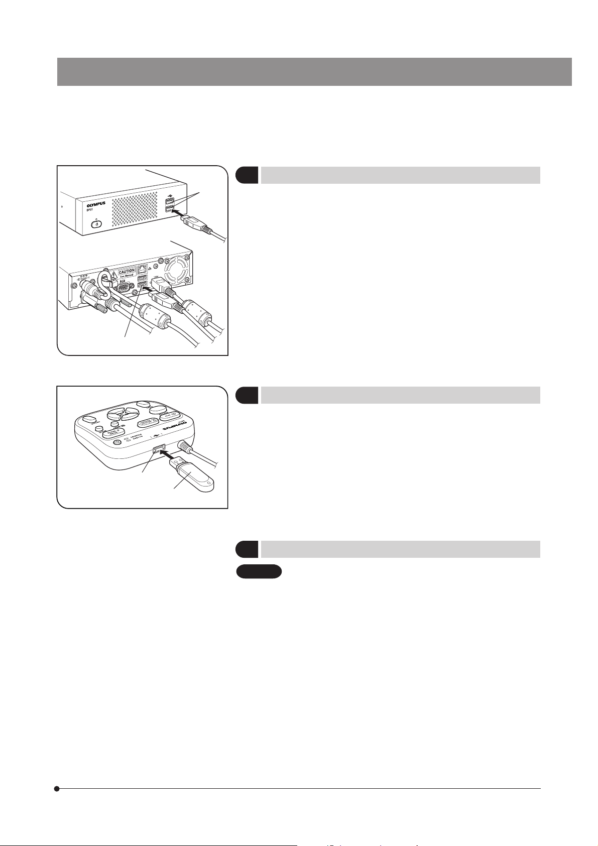
Connecting the Hand Switch
6
Insert the USB cable connector of the hand switch into one of the USB
ports @ of the control box.
}The control box has a total of four USB ports. The hand switch function is
identical regardless of the connected USB port so the user can select
any USB port as desired.
Inserting the USB memory
7
Insert the USB memory @ all the way into the USB port ² of the hand
switch.
(Fig. 7)
(Fig. 8)
2
Fig. 8
1
Applicability of USB Device
8
CAUTION
USB memory
}Do not connect a USB device other than the USB memory provided with
the DP21 into the USB port of the hand switch. Otherwise, malfunction
may result. If you use a commercially available USB memory, connect it
to a USB port of the control box. The USB memory provided with the
DP21 can also be used by inserting it into a USB port of the control box.
}The ACCESS LED of the hand switch lights or blinks during data access
(for saving the recorded image, etc.). Do not disconnect the USB memory
during this period.
}The USB memory can be disconnected without special disconnection
processing such as that required with a PC. The USB memory can be
disconnected anytime except when the ACCESS LED of the hand switch
is lighting or blinking.
}A USB memory with a special function such as the security or password
function cannot be used.
15
Page 20
CAUTION
USB mouse/keyboard
}The USB mouse and keyboard are to be purchased separately. If you
want to use them, prepare the ones that comply with the following standards or contact Olympus.
USB mouse: Should be compatible with Windows XP and USB2.0.
USB keyboard: Should be compatible with Windows XP, USB2.0 and the
alphanumeric keyboard.
For the latest information, visit the Olympus website or consult Olympus.
http://microscope.olympus-global.com/en/
}It is not possible to install a special driver for the mouse or keyboard in
the DP21. As a result, if a device requires a special driver, only the standard functions of the device are available with the DP21.
}When using a USB keyboard or mouse, connect it to a USB port of the
control box.
1
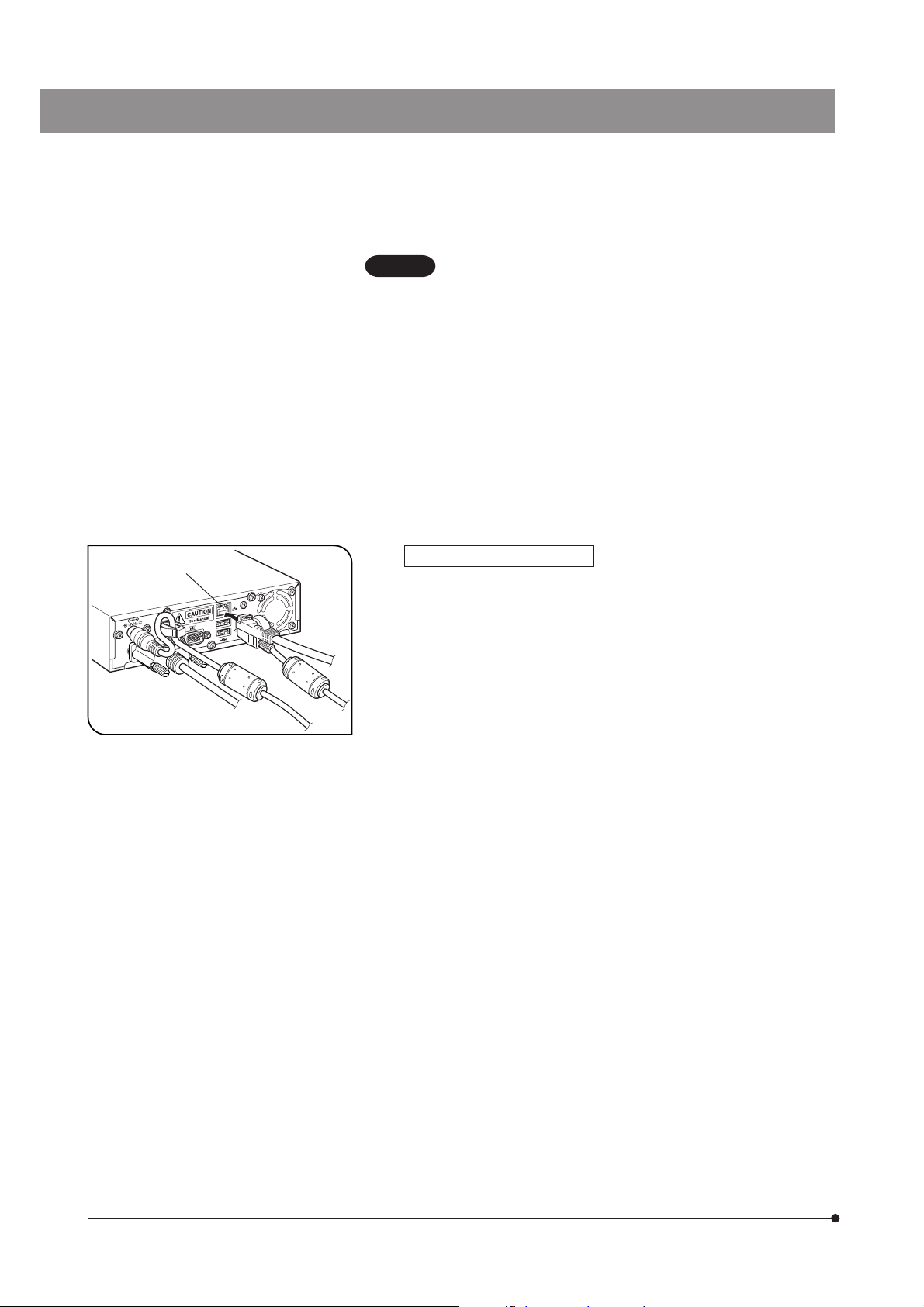
Connection to a LAN (Fig. 9)
Insert the LAN cable into the LAN connector @ on the rear of the control
box.
}The LAN connection is necessary only when the DP21 needs to access
a PC on a network. It is not necessary when saving the recorded data in
a USB memory.
}For network connection, the network setting is required in addition to the
LAN cable connection. See page 57 for details on the network setting.
Fig. 9
16
Page 21
SAL System
2-5 Basic Image Recording Procedure
This section describes the basic operating procedure of the DP21 (from turning power ON to image recording) and the
initial setting method.
The information in this section is enough for mastering the basic method for recording still images and movies.
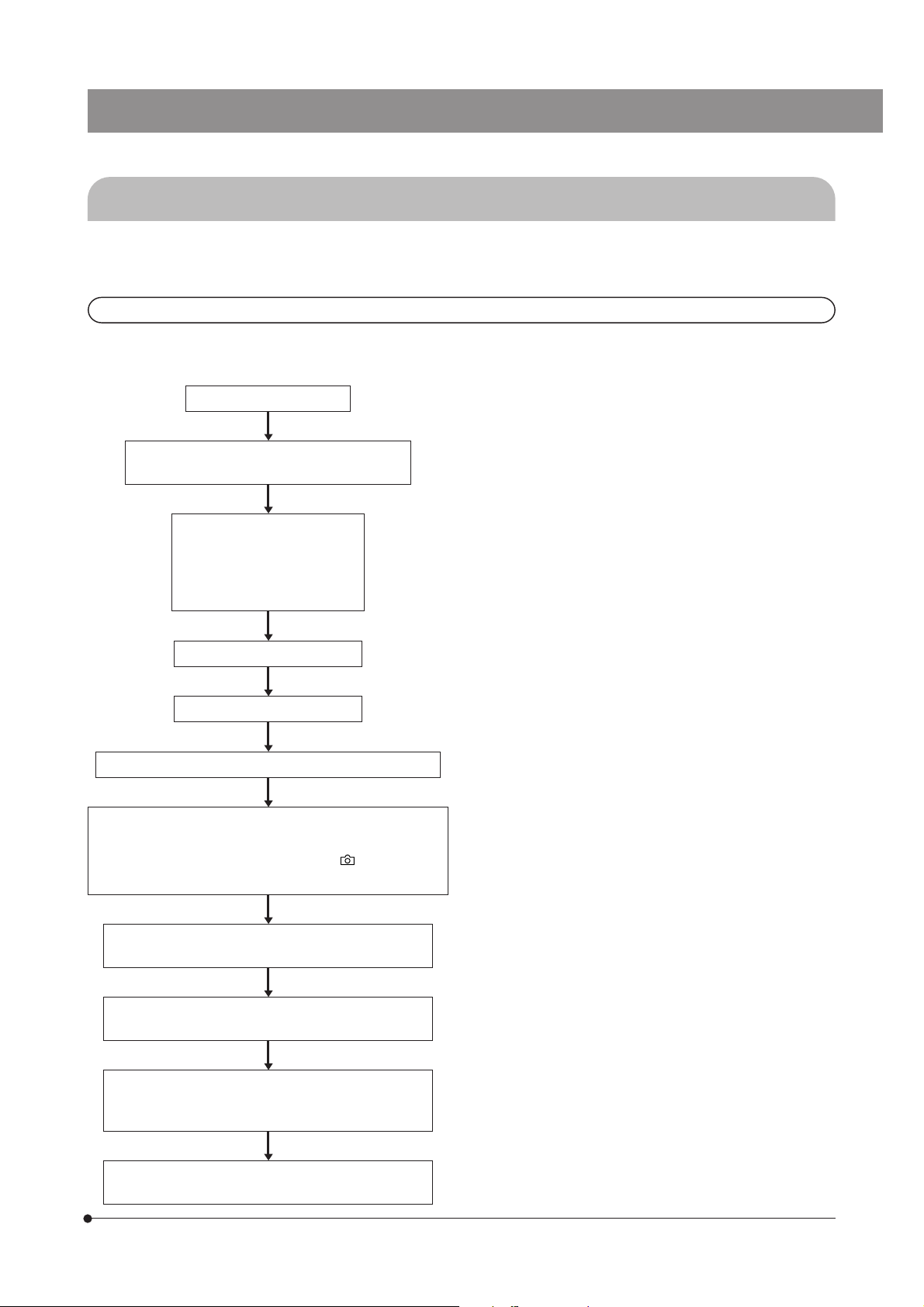
2-5-1 Operation flow
}Perform the optical adjustments sufficiently before proceeding to the following.
}Adjust the parfocality of the microscope’s eyepieces and the monitor display using the camera adapter. (For the parfocal
adjustment method, refer to the instruction manual for the camera adapter.)
Connect a USB memory.
Set the main switch of the control box and
camera head to ON.
Initial setting (First time only)
· Language setting
· Scale setting
· Date/Time setting
· Monitor resolution setting
Select the REC AUTO mode.
Set the live image resolution.
Select the recording (TV) light path on the microscope.
Adjust the microscope brightness.
· Engage an LBD filter in the microscope light path.
· Set the microscope’s control to the “
the voltage specified for photographing.
Confirm the focus and brightness of the specimen
on the monitor screen.
Perform OTWB (One-Touch White Balance) adjustment.
Check framing (recording area).
(If the live image magnification is modified, return it
to 1X.)
Press the EXPOSE button to capture and record
image.
(p. 15)
² (p. 19)
3 (p. 20)
6 (p. 22)
” marking or
@ (p. 18)
7 (p. 22)
8 (p. 23)
Note on initial setting
Before initial setting, disconnect the USB memories
(including the removable media devices such as
HDD) from the hand switch and/or control box. They
can be reconnected after completion of restarting
(auto restart) after the setting.
Tip Focusing method
· The live image magnification can be zoomed into
1x --> 2x --> 4x. Focusing will be easier at a high zoom
ratio (p. 27).
· The accurate focusing can be identified easily by
displaying the focusing indicator on the monitor
screen (p. 37).
· If the image is too bright, dim the brightness using
an ND filter(s).
(Note) If the brightness is adjusted by controlling the
voltage intensity, the color temperature of the
illumination may change and affect the recorded
image.
· Set the image quality (p. 30), SPOT metering (p. 26),
AE LOCK (p. 27) and exposure adjustment (p. 26)
as required.
· The brightness and color tone of the live image displayed on the monitor may sometimes differ from
those that are recorded actually.
17
Page 22
1
Fig. 10
2
Fig. 11
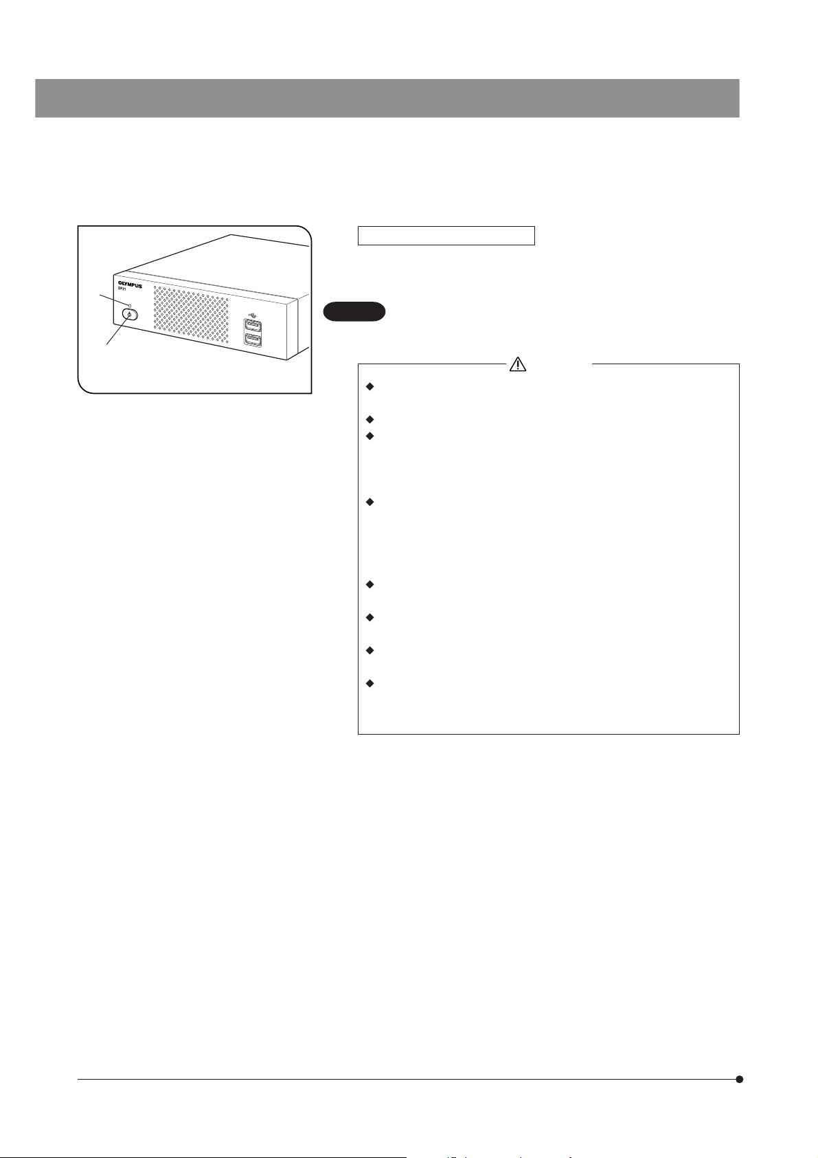
Turning Power ON/OFF
1
Turning power ON
1) Set the main switch of the camera head to “ I ” (ON).
2) Press the main switch @ of the control box to turn it ON.
Turning power OFF
Press the main switch ² of the control box to turn it OFF.
}With the DP21 system, a main switch is provided on the hand switch,
(called the standby switch), control box and camera head. The following
table shows what happens when each of these main switches are set to
OFF.
Control box Shuts down the system (approx. 30 sec. for startup and 10 sec. for shutdown).
Once the system is shut down, it cannot be started up from the hand switch. The STANDBY LED
turns off when the system is shut down.
Hand switch Set the system to standby mode (approx. 10 sec. for startup and. 3 sec. for sleep).
The STANDBY LED blinks in standby mode.
Camera head Switches only the camera OFF. The control box and hand switch are left ON. Usually, this switch
does not need to be set to “ ” (OFF).
The pilot LED on the camera head lights when it is ON.
}With the standalone system, turning the control box or hand switch OFF automatically turns the camera head OFF, so it
is not required to operate the main switch of the camera head. It is recommended to leave the camera head permanently
ON.
}To protect the system, it is recommended to use the main switch of the control box to shut down the system whenever
possible.
}If the DP21 system is used for a long period without shutting it down, the system may sometimes resets and restarts
automatically (the restart time is about 30 seconds). To protect the system, it is recommended to shut down the system
periodically at an interval of about once a week.
If the camera head is switched OFF during use
If the camera head is turned OFF during use of the DP21 by accidentally setting the main switch to OFF or disconnecting
the camera cable, the system detects that the camera head is not connected and displays an error message. If this
happens, press the main switch of the control box to shut down the system. After this, either set the main switch of the
camera head to ON or reconnect the camera cable and then press the main switch of the control box to restart the system.
18
Page 23
1
Fig. 12
2
SAL System
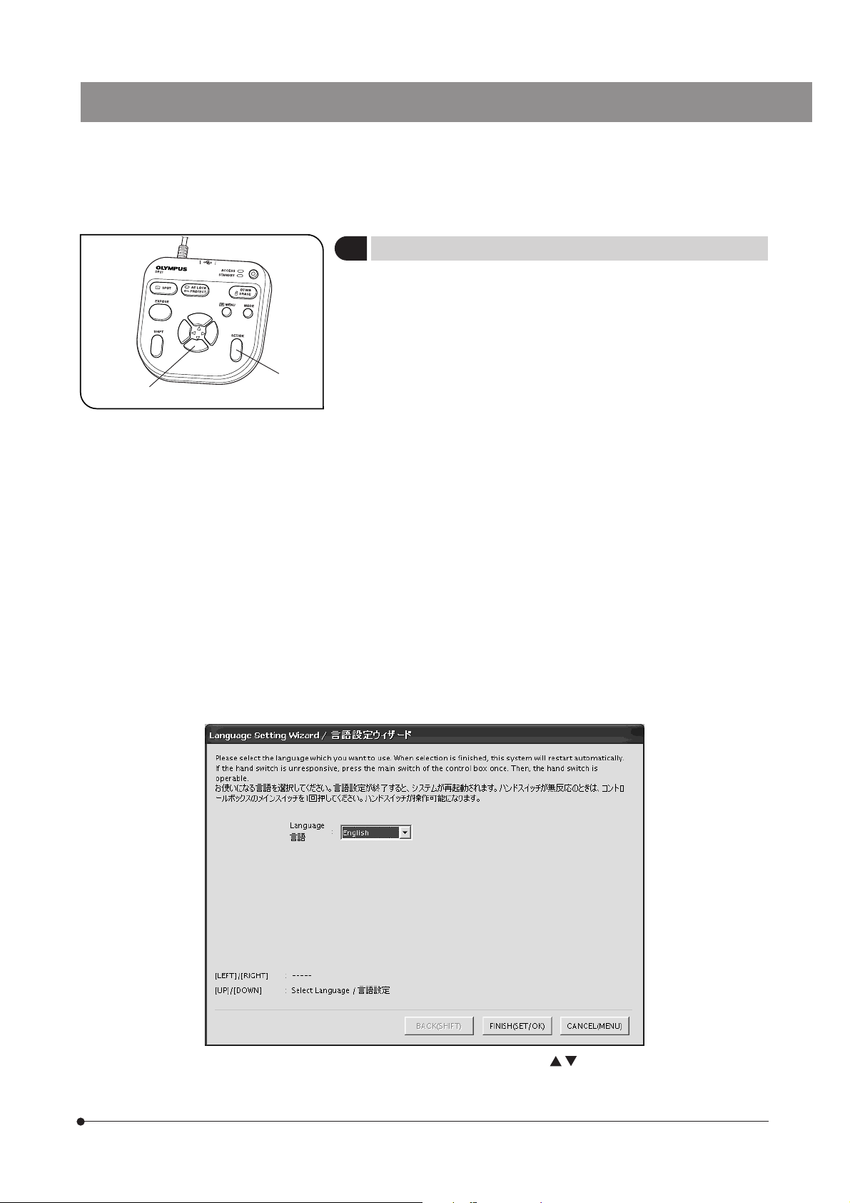
Initial Setting
2
To use the system correctly, it is required to set the language and scale
magnification at the beginning.
Set them by following the window displayed when the system is turned
ON for the first time.
}The setting window is not displayed the next time the system is turned
ON. Even when they are not set at the first time, they can be set anytime
using a menu.
1. The setting window appears when the system is turned ON.
}Before initial setting, disconnect the USB memories (including the re-
movable media devices such as HDD) from the hand switch and/or control box. They can be reconnected after completion of restarting (auto
restart) after the setting.
2. Set the language by following the wizard.
3. Also set the scale magnification (magnifications of the camera adapter
and objective in use) in the same way. The DP21 restarts after completion of the setting.
}See page 54 for the language setting and page 35 for the scale magni-
fication setting.
}The clock setting and monitor resolution setting windows are not dis-
played automatically. For their setting methods, see “Date/Time Setting
(p. 53)” and “Monitor resolution setting (p. 56).”
}Image recording is possible even when the date/time are not set, but the
date/time information in the file name of the recorded image becomes
incorrect. To prevent this, it is recommended to set the date and time
before recording an image.
}The monitor resolution is usually set automatically but may not be set
with certain monitors. To prepare for such a case, it is recommended to
set the monitor resolution in advance on this opportunity.
(Example) Language setting Default: English
Operation using the hand switch: Select the language with the cursor buttons @ and press the SET/OK button ²
to enter the selection.
Operation using the mouse: Click on the scroll button to select the language and click on [FINISH (SET/OK)] to enter the
selection.
19
Page 24
1
Fig. 13
Fig. 14
2
1
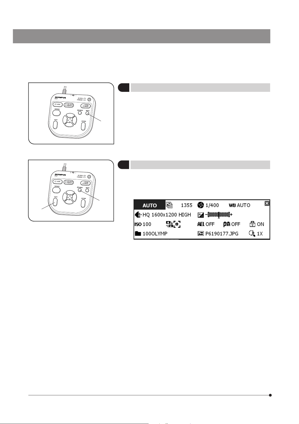
Selecting the Mode
3
The MODE button @ can be used to select the REC AUTO (auto-exposure recording), REC MANUAL (manual-exposure recording) or PLAY (playback) mode.
}When the DP21 is turned ON and the REC AUTO or REC MANUAL mode
is selected, the live image is displayed on the monitor screen.
}The default setting is REC AUTO. From the next time, the system is started
up in the mode selected when it was turned OFF the last time.
Viewing/Hiding the INFO Display
4
When the live image is displayed, the INFO display is displayed on the
upper right of the screen as shown in the following example (which shows
the display in REC AUTO mode). For details on the INFO display, see
MENU/INFO display (p. 10).
While holding the SHIFT button @, press the MENU button ² to view or
hide the INFO display alternately.
}Even when the system is turned OFF with the INFO display hidden, it is
displayed the next time the system is turned ON.
20
Page 25
1
SAL System
Viewing/Controlling the MENU Display
5
1. Press the MENU button @ to view or hide the MENU display alternately.
For details on the MENU display items, see MENU display (p. 10). The
MENU display is hidden with the default setting.
2. Press the cursor buttons ² to select an item and press the SET button ³
to enter the selection.
2
Fig. 15
Setting item tabs
Basic operation flow of the MENU display
Viewing the MENU display:
Press the MENU button to view the MENU display.
3
Setting item icon
Setting content list
Selecting a tab:
Press the cursor buttons
selection of a setting item icon. Press to return to the beginning of tab selection step.
Selecting an icon:
Press the cursor buttons
in the setting content list. Press
Selecting a setting content
Press the cursor buttons
a pull-down item (resolution, etc.), press the cursor buttons
select the desired item.
Entering the setting content:
Press the SET button to enter the selected setting content.
to select a setting item tab. After it, pressing --> enables
to select a setting item icon. After it, pressing --> enables selection
to return to the beginning of icon selection step.
to place the cursor on the desired setting content. When setting
after placing the cursor and
21
Page 26
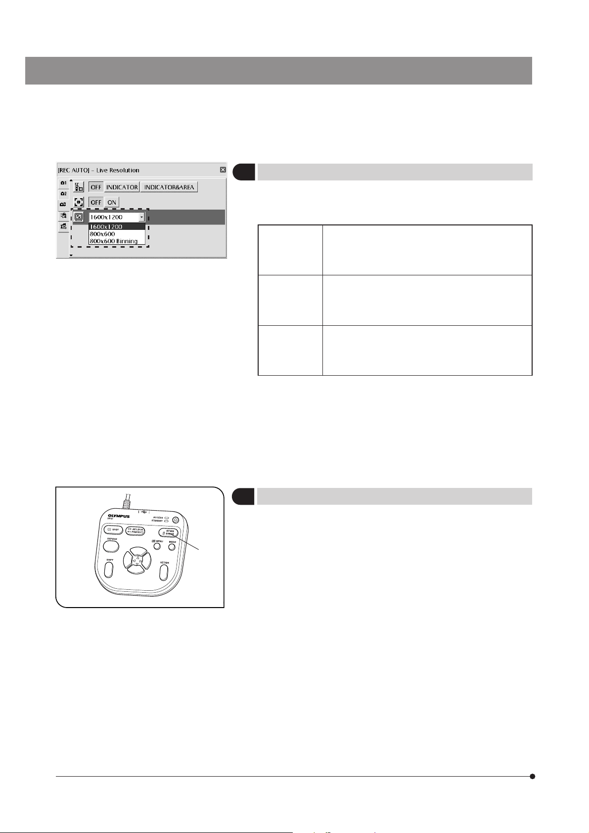
Fig. 16
Setting the Live Resolution
6
With the DP21, the resolution of the live image can be selected from three
options of UXGA:1600 x 1200, SVGA:800 x 600 and SVGA (binning) 800 x
600. The characteristics of each resolution are as follows.
1600 x 1200 High-definition image observation/recording, which is
recommended when viewing clear image on a large
monitor screen.
Frame rate: 15 fps
800 x 600 Image observation at a high frame rate displays smooth
live images even when the target moves during examination, etc.
Frame rate: 27 fps
800x 600
(Binning)
}If the set resolution differs from the resolution available with the monitor,
the image is magnified or reduced according to the monitor screen size.
When the image is magnified, the noise in it is also magnified and may
become noticeable.
}Live images are magnified according to the resolution of the monitor.
However, the optimum aspect ratio may sometimes not be achieved. To
display the images at the optimum aspect ratio, refer to “Monitor resolution setting" on page 56.
Sensitivity is 4 times higher than other modes. Observation and recording of bright image are possible even
the target is dark.
Frame rate: 27 fps
Default: 1600 x 1200
Fig. 17
1
OTWB (One-Touch White Balance)
7
Adjust the white balance before recording to record image in optimum
color tones.
1. Display an exclusively white live image.
· During transmitted light observation, remove the specimen.
· During reflected light observation, set a piece of white paper in place of
the specimen.
2. Press the OTWB button @ to adjust the white balance.
3. When the white balance is set, message “White balance setting is completed.” is displayed on the monitor and disappears automatically in 3
seconds. This message can also be switched off by pressing any button
other than the main switch.
}If the adjustment fails, message “white balance setting failed.” is displayed.
As this message does not disappear automatically, press the SET/OK
button to switch it off and retry the adjustment.
}The white balance adjustment fails when the live image is not com-
pletely white, the exposure is inappropriate (too bright or too dark), etc.
}The white balance can also be adjusted using AUTO WB and manual (by
means of direct entry of color temperature) as well as OTWB (One-Touch
White Balance), and the adjustment mode can be selected in the MENU
display. For details, see Setting the white balance (WB) mode (p. 33).
22
Page 27
1
Fig. 18
²
SAL System
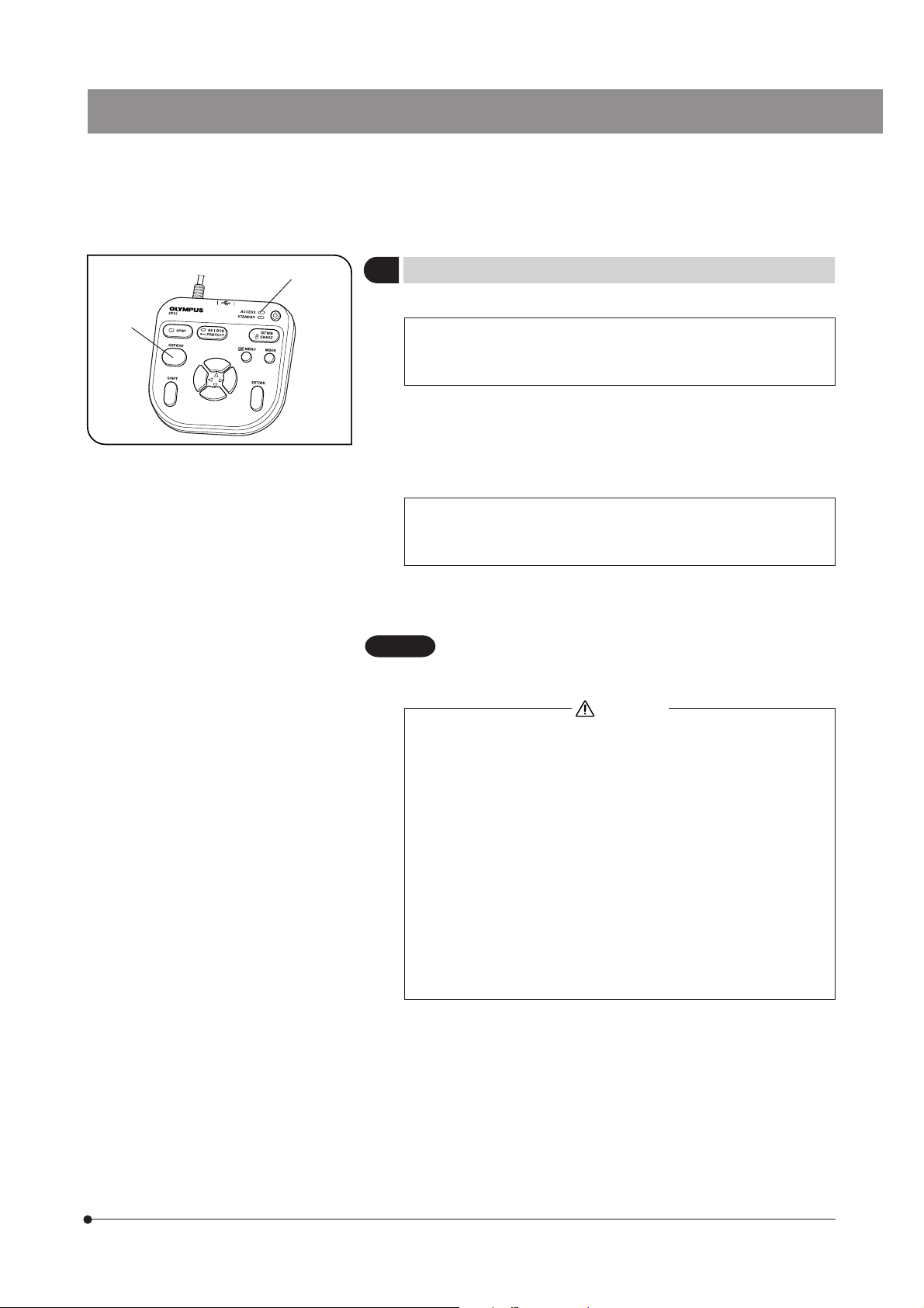
Recording Still Images
8
1. On the microscope, frame the image to be recorded and focus on it.
Tip
To facilitate focusing, use the zoom display of the live image (p. 27) or
display the focusing indicator (p. 37).
2. Press the EXPOSE button @ to record the still image, which is saved in
the USB memory connected to the control box or hand switch.
}Switching the Rec View setting (p. 34) ON displayed the recorded image
temporarily during live image display. (With the default, the recorded image is displayed for 5 second after recording.)
Tip
The image save destination can be changed (p. 31). The image can
also be saved in the networked PC by advance setting.
3. The ACCESS LED lights during recording of the image. Message “Saving
image” is also displayed on the center of the screen.
4. The INFO display shows the number of remaining image.
CAUTION
When the number of remaining image reaches 0, warning
message “MEMORY FULL” is displayed on the monitor screen.
CAUTION
· Do not disconnect the USB memory while the ACCESS LED ² is
lighting.
· As the data quantity varies depending on the recording target, more
images than the number of remaining image may sometimes be
recordable. Also, the counter may not decrement after recording or
may not increment even when an image is erased.
· The number of remaining image varies depending on the capacity
of the USB memory.
· The USB memory has its own service life. Its capacity may decrease
depending on its conditions.
· It is not possible to record more than 10,000 images even when the
USB memory has a remaining idle capacity.
· The folder and file names of the recorded images are created auto-
matically. See page 33 for details.
23
Page 28
2
1
Fig. 19
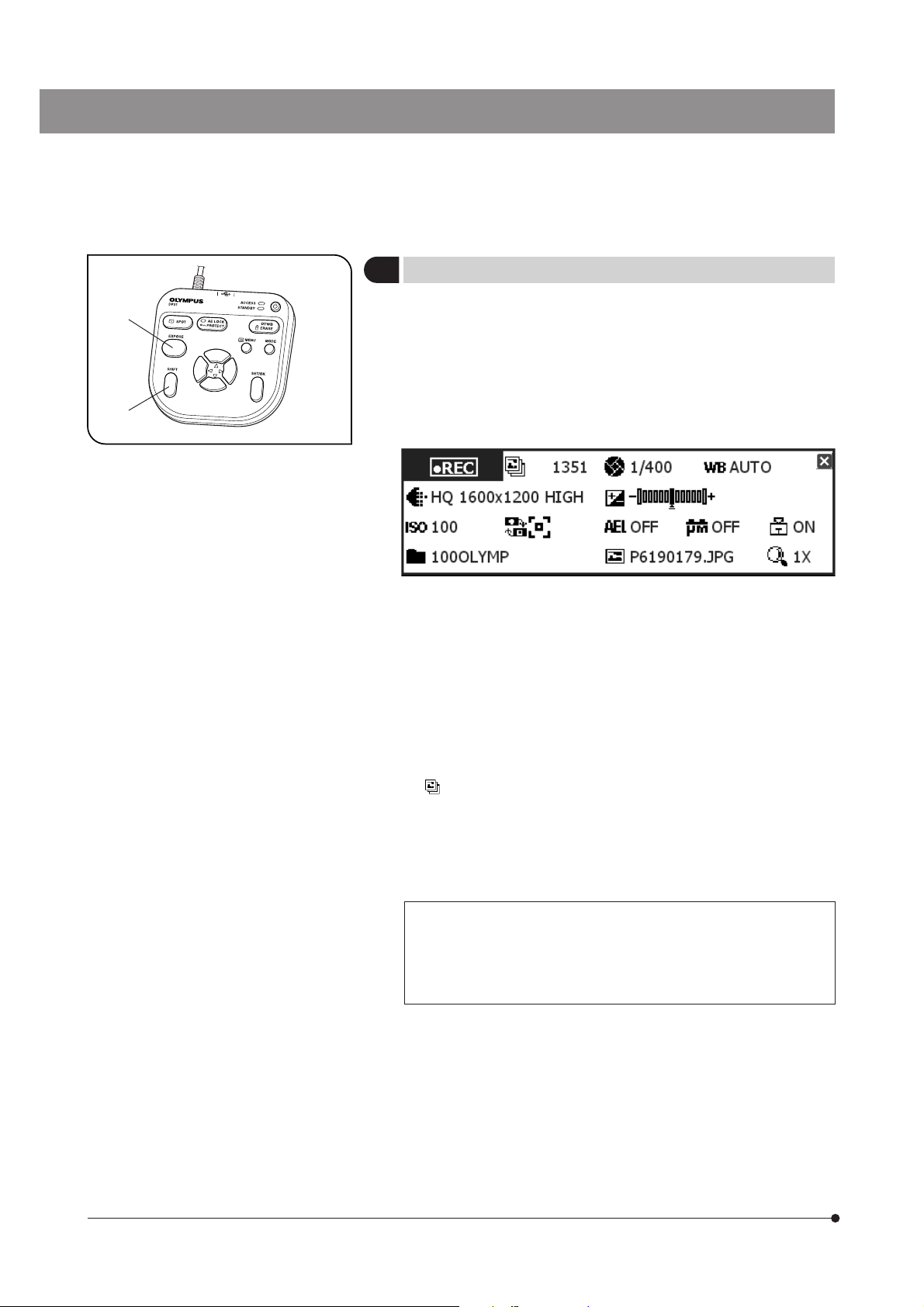
Recording Movies
9
1. On the microscope, frame the image to be recorded and focus on it.
2. While holding the SHIFT button @, press the EXPOSE button ² to start
movie recording.
3. To stop movie recording, press the EXPOSE button ². The movie is saved
in the USB memory.
}The INFO display shows the following information during movie record-
ing (the MODE display shows “REC”).
}The image size and format of the recorded movie are as follows and
cannot be modified.
Image size: 400 x 300
Format: Non-compressed AVI
}The settings cannot be changed in the middle of movie recording. They
should be changed after completing the recording.
}A movie can be recorded for up to 5 minutes (this period is variable
depending on the frame rate and storage medium capacity). Movie recording may stop anytime automatically when the maximum file size is
reached or the storage medium runs out of capacity.
}“
” on the INFO display indicates the number of recordable still-image
images, and the number of recordable movies is not displayed.
}When the system is turned OFF in the middle of movie recording, the
movie ends at that point.
}The folder and file names of the recorded movies are created automati-
cally. See page 33 for details.
24
Tip
The movie save destination can be changed (p. 31).
However, the movie frame rate may drop depending on the data write
speed of the recording medium (at the time of playback, such a movie
look like a fast-forward movie).
Page 29
SAL System
2-6 Recording Function Setting/Operation (REC)
2-6-1 Operation using the hand switch
This section describes the method of operating the basic functions using the hand switch. The hand switch has buttons
to which the functions frequently used in microscope observation are assigned to facilitate the recording of clear images.
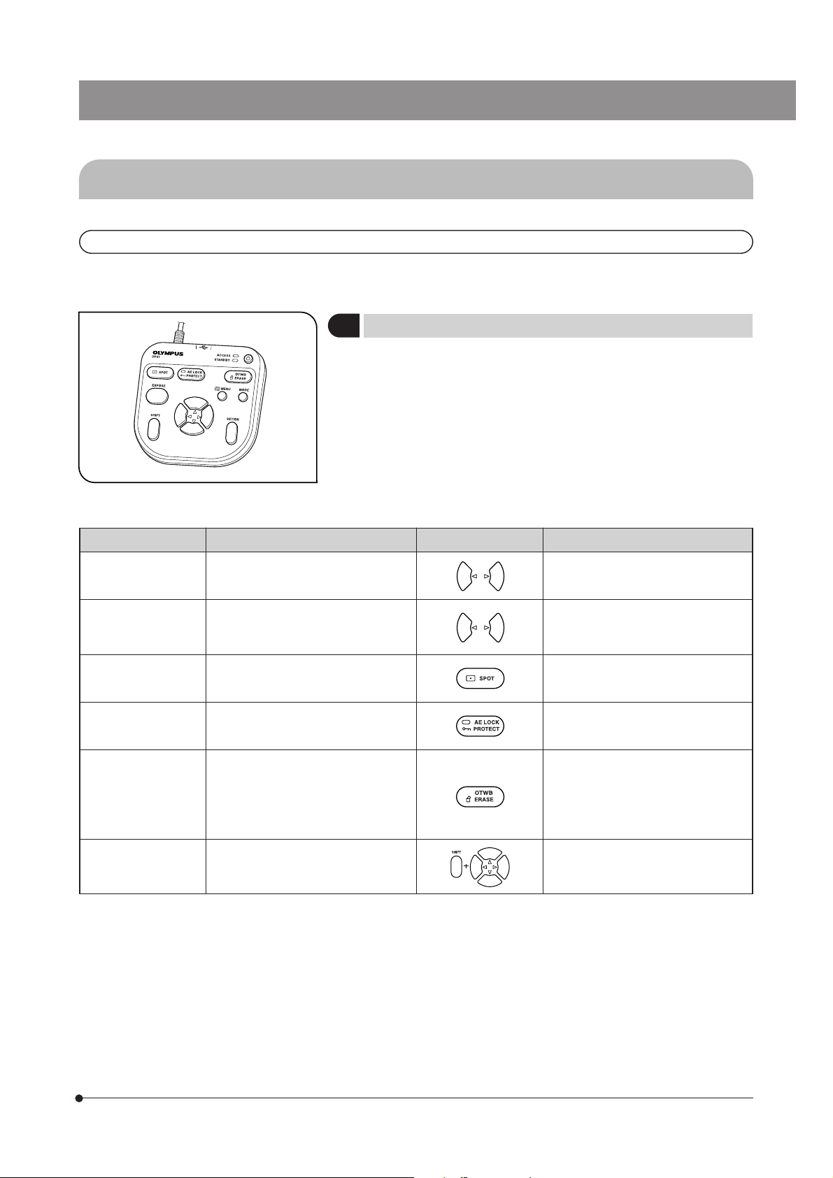
Available Functions
1
The hand switch of the DP21 incorporates the following functions. For
details of each function, see the description in the applicable pages.
Fig. 20
Name Function Buttons Remark
Exposure adjustment
(AUTO mode)
Exposure time setting
(MANUAL mode)
SPOT metering Switches the metering area between
AE lock Locks the exposure time set by AE
OTWB To reproduce optimum colors, image
Scrolling Scrolls the zoomed image. Scrolling of the image is also possible
Modifies the exposure time set by AE
(Auto Exposure).
Sets the exposure time by direct entry
of the figure.
normal (30%) and SPOT (1%).
(Auto Exposure).
a white object, measures the white
balance and stores the optimum white
balance for actual recording status in
the DP21.
To enter the exposure time directly,
press the MODE button to select the
REC MANUAL mode.
Select the metering area according to
the specimen. See p. 26 for details.
Set the entire live image white when
executing OTWB.
See p. 22 for details.
by holding the SET/OK button instead
of the SHIFT button.
25
Page 30
12
Fig. 21
1
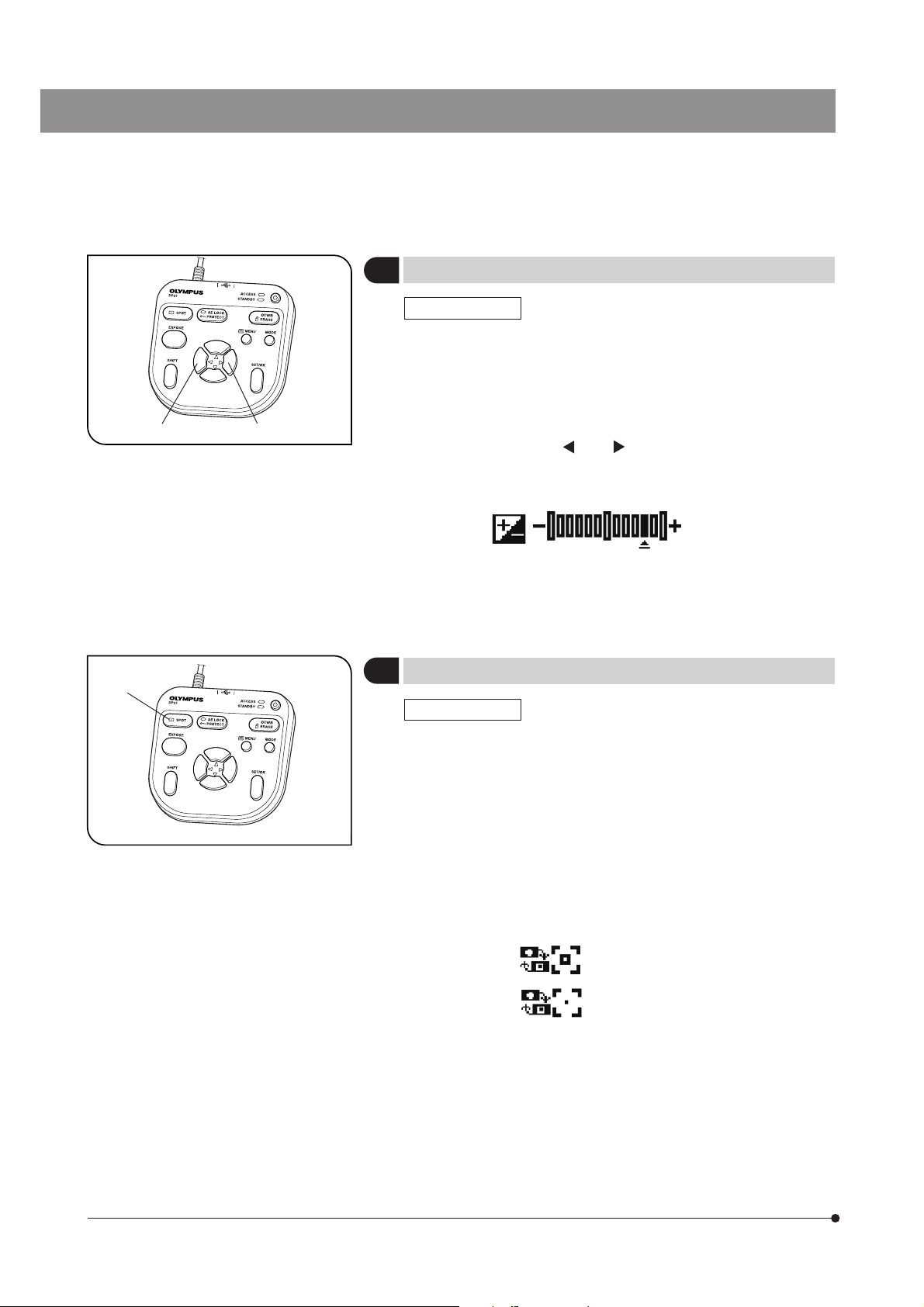
Exposure Adjustment
2
REC AUTO mode
The exposure time set by AE (Auto Exposure) can be corrected (by up to
2 EV in 1/3 EV steps).
When the specimen is dark, +EV correction will extend the exposure time
and give an over-exposure type effect. When it is bright, the -EV correction will shorten the exposure time and give an under-exposure type
effect.
Press the cursor button
value. The setting can be checked on the following scale at the bottom
of the INFO display.
}Switch off the MENU display before the exposure adjustment. If the MENU
display is shown, press the MENU button on the hand switch to hide it.
SPOT Metering Setting
3
REC AUTO mode
@ or ² to set the exposure adjustment
(Example) +4/3EV
-2EV 0 +2EV
Fig. 22
}When the observation target is dispersed in the image, the image may
become too bright or too dark due to the effect of the background. In
such a case, the problem may sometimes be improved by changing the
metering area.
}The center average metering is set normally.
· Center average metering: Photometry of the 30% area on the image
center.
· Spot metering: Photometry of the 1% area on the image center.
1. Press the SPOT button @ to switch the metering area between SPOT
and Average.
The INFO display shows the current setting.
Center average metering (30%)
Spot metering (1%)
2. The metering area can be displayed or hidden by setting in the MENU
display. When it is set to be hidden, it appears only when the SPOT
button is pressed but disappears in 3 sec.
26
Page 31

2
Fig. 23
1
SAL System
AE Lock Setting
4
REC AUTO mode only
1. Press the AE LOCK button @ to lock the current exposure time. The AE
LOCK LED ² lights and the INFO display shows the locked exposure
time.
2. Press the AE LOCK button @ again to cancel AE LOCK.
When AE LOCK is set, the metering area, ISO speed and exposure adjustment cannot be set.
}When a specimen dispersed in dots is observed using AE, moving the
stage may sometimes vary the exposure time and make the image too
bright or dark. AE LOCK is useful in such a case for observing the target
at constant brightness.
4
2
3
Fig. 24
5
1
Zooming/Scrolling
5
1. Press the MENU button @ to hide the MENU display.
2. Press the cursor button
of the live image.
4x --> 2x --> 1x.
3. Pressing one of the cursor buttons while holding the SHIFT button | or
SET/OK button 5 scrolls the image in the direction indicated by the
pressed button. The entire image area can be scrolled even during 2x
and 4x zoom display.
}A scroll arrow is displayed when the image is zoomed in. Scrolling can
be used only when Zoom (2x and 4x) is displayed.
Tip
Zooming and scrolling are not available when the MENU display is displayed.
² or ³ to change the electronic zoom ratio
² switches it to 1x --> 2x --> 4x and ³ switches it to
27
Page 32

Composite Button Operations
6
Pressing two buttons makes it possible to perform a quick setting as shown in the following table (¦: Possible / :
Impossible). To perform this, ensure that the MENU display is hidden, hold the “Held button” and press the “Switching
button.”
Composite buttons Mode
Held button Switching button REC PLAY
Shift
or
SET/OK
SET/OK
Shift
Shift
Shift EXPOSE Movie recording starting
MENU
Cursor button
MENU
or
MODE
MENU
Cursor button
Main switch
¦¦
¦
¦
¦
¦¦
¦
¦
Scrolling when the image is zoomed (2x or 4x).
(This can also be used in left/right scrolling in
the save destination window.)
Scale data setting change
INFO display view/hide switching
Available only when the index images are displayed.
Thumbnail list page switching
System startup at the resolution of the monitor
display (SVGA 800 x 600).
After about 30 seconds from the startup with
the power switched to ON, the AE lock LED
will light for about 1 second. Press only the
MENU button while the AE lock LED is on.
Setting operation
Page
27
35
20
51
24
56
28
Page 33

SAL System
2-6-2 Operation using the MENU display
This section describes the operation method of the functions that are available in the MENU display on the monitor
screen. This section pertains to the recording operation (in the REC AUTO/REC MANUAL modes). See page 21 for the
basic operations and flow of the MENU display.
Settings in the REC modes
· Use the MODE button to select the REC AUTO or REC MANUAL mode.
· Use the MENU button to view the MENU display on the monitor screen.
· Be sure to press the SET/OK button after each setting to enter it.
Viewing the MENU Display
1
1. Press the MENU button to view or hide the MENU display.
2. Press a cursor button to place the cursor on the desired item.
3. Press the SET/OK button to enter the selection.
}For applied functions and settings, see “Applied operations” (p. 34).
Page select tabs
Tab Content
Page for the camera’s basic functions
The image quality mode, ISO speed, etc. can be set in this page.
Page for the camera’s applied functions.
Rec View, Scale, etc. can be set in this page.
Page for the camera’s display functions.
The focusing indicator, AE area, etc. can be viewed or hidden in this page.
Page for the measurement functions.
Measurements of image can be started from this page.
Page for options.
Selection of the folder of the image to be played and setting of the language and date are available.
Page for the guidance on microscope.
The guidance can be displayed and manipulated.
*This page is displayed only when the conrol box (U-CBS, etc.) is connected.
29
Page 34

Image Quality Mode Setting
2
Default: HQ
}Select the quality of the recorded image.
The image quality improves as the setting is advanced from “SQ-H” -->
“SQ-L” --> “HQ” --> “SHQ” --> “TIFF.”
Image quality mode Compression rate Save format Recording pixels File capacity
TIFF No compression TIFF 1600 x 1200 Approx. 5760 KB
SHQ LOW (1/2.7) JPEG 1600 x 1200 Approx. 2140 KB
HQ HIGH (1/8) JPEG 1600 x 1200 Approx. 720 KB
SQ-L LOW (1/2.7) JPEG-LOW 800 x 600 Approx. 535 KB
SQ-H HIGH (1/8) JPEG-HIGH 800 x 600 Approx. 180 KB
}The quality is fixed at “SQ-HIGH” when the binning is set (p. 22).
}The compression rates are as follows. SHQ (TIFF): No compression; SHQ (JPEG): 1/2.7; HQ (JPEG): 1/8; SQ (JPEG-LOW):
1/2.7; SQ (JPEG-HIGH): 1/8.
ISO Speed Setting
3
}Select the sensitivity (ISO speed) in image capturing. The figures are set
based on the ISO speeds of photo films.
Three options of 100, 200 and 400 are available. The larger ISO speed
is more suitable for recording of dark specimens or quickly-moving
objects.
Image quality
Default: 100
CAUTION
4
The larger ISO speeds are suitable for recording of dark specimens, but they also increase the image noise.
Select the optimum setting according to situations.
Sharpness Setting
}Select the image sharpness. The sharpness refers to the degree of
contour enhancement of image.
Three options of “NORMAL,” “SOFT” and “OFF” are available.
The contour enhancement attenuates as the setting is changed from
“NORMAL” to “SOFT” and then to “OFF.”
“NORMAL” sharpens the image contours and is suitable for appreciation of prints, etc. “SOFT” reproduces contours in a
natural feeling. “OFF” does not apply sharpness correction and is therefore suitable for subjecting to post image processing on a PC, etc. Select the optimum setting according to situations.
Default: NORMAL
30
Page 35

SAL System
Save Folder Setting
5
When more than one DP21 unit records and saves images into the same
folder in a network PC, etc. at the same timing, an error about the impossibility of saving the recorded images may occur. Wait a while and retry
recording the images or save the image files in different folders.
AUTO
When the save destination is set to “AUTO,” the images are saved in a USB removable medium such as the USB memory
connected to the hand switch or control box. If multiple media are connected, the images are saved in the first connected
one. If a single medium is divided into multiple partitions, the images are saved in the first drive.
The recorded images are saved in the folder that is created automatically in the medium. The folder names as well as the
file names of the recorded images are created automatically. For details on the folder and file names, see “Folder and File
Names (p. 33).”
MANUAL
The user can specify the image save destination, which is shown in @. The save destination can be set using only the
hand switch, but the use of the keyboard is required if the save destination is protected by a password, etc.
1. Place the cursor on “MANUAL” and press the SET/OK button.
2. Similarly, place the cursor on ² and press the SET/OK button. The [Folder Select] window as shown below is displayed.
3. Select the save destination location.
}If the save destination folder name is turned into garbled characters due to the use of special characters, etc. malfunction
may result.
Setting the save folder ²
Default: AUTO
Save folder @
[Folder Select] window
31
Page 36

Specifying the save folder by the address
The save destination can be specified by entering the folder address. In addition, a pull-down menu is also available
listing the recently-specified addresses (up to 10 addresses) so that the user can also select the desired address from
them.
1. Place the cursor on
2. Press the cursor button
save destination address directly from the keyboard.
3. Press the SET/OK button of the hand switch to enter the save destination. If you are using the mouse, click on [OK] in the
[Folder Select ] window.
4. To cancel the operation, press the MENU button or click on [CANCEL].
5. If you want to specify the destination from the folder tree displayed below instead of the address, press the SET/OK
button. As this moves the cursor to
}The direct entry of the address is possible only when the keyboard is connected. When specifying the network PC, enter
the full paths including the PC name and folder name.
Specifying the save folder from the tree
The save destination can also be specified from a folder tree. A scroll bar is displayed if the displayed folders have long
paths. Up/down scrolling of the folder tree is possible using the up/down cursor buttons of the hand switch, and left/right
scrolling is possible using the Shift + left/right buttons.
1. Place the cursor on
2. Select the save destination from the folder tree using the cursor button of the hand switch or the mouse.
3. Press the SET/OK button of the hand switch to enter the save destination. If you are using the mouse, click on [OK] in the
[Folder Select] window.
4. To cancel the operation, press the MENU button or click on [CANCEL].
5. If you want to specify the destination by the address instead of using the folder tree, place the cursor on “RETURN” above
the folder tree and press the SET/OK button. As the cursor moves to
and press the cursor button .
to select one of the save destinations listed in the pull-down menu. Alternatively, enter the
, select again.
and press the cursor button .
, select again.
32
}The following operations are available on the hand switch.
Button Function
Moves the cursor up.
Moves the cursor down.
Collapses the expanded slave folder so that the master folder can be selected.
Expands the specified folder if it has slave folders.
SET/OK
MENU
}The setting is sometimes impossible if the save destination folder is specified in the networked PC. If this happens, wait
a while and retry the folder specification; this may sometimes make the setting possible.
The trouble mentioned above is caused because the result of the PC search of the specified folder may vary in each
search operation.
Sets the selected folder as the save folder and closes the [Folder Select]
window.
Closes the [Folder Select] window (by cancelling the save folder setting
operation).
Page 37

SAL System
White Balance (WB) Mode Setting
6
The white balance adjustment mode can be selected from the
following three options.
Mode Function/Characteristics
AUTO Identifies the white part in the live image and adjusts the white balance automatically. The white
balance adjustment is executed automatically whenever the illumination brightness changes. However, when the live image contains little white part or with certain specimen type or brightness, the
white balance cannot be adjusted properly and the optimum color tone cannot be obtained.
MANUAL Recalls the white balance value preset for each color temperature. When the user specifies a color
temperature, the color toe matching it can be obtained.
(Available color temperature settings are OTWB, 3000K, 3700K, 4000K, 4500K, 5500K and 6500K.)
}When OTWB is selected in the MANUAL mode, the white balance value set when the OTWB button on the hand switch
was last pressed is recalled. Therefore, if the lighting condition such as the brightness was different from the moment the
OTWB button was last pressed, the optimum color tone would not be obtained. If this happens, view a white image on the
live view and execute the OTWB adjustment operation again (p. 22).
}Pressing the OTWB button of the hand switch sets the OTWB mode automatically.
Folder and File Names
7
When an image is recorded, the DP21 automatically creates a folder in the image save destination and saves the image
file in it. The folder and file names are created automatically as shown below.
Default: AUTO
Folder and file names
Each image recorded with the DP21 is automatically given the folder and file names as shown below.
Folder name File name
Folder No.: 100 - 999 Month (1 - C)
Day (01 - 31)
*The “month” in the folder name is expressed with “1” to “9” for January to September, “A” for October, “B” for November and
“C” for December.
When the save folder setting is “MANUAL” and the folder is specified manually, the folder and file are named as follows.
<User-specified folder> Pmddxxxx.JPG
The file name extension is set according to the image quality mode as follows.
TIFF : .TIF
SHQ, HQ, SQ : .JPG
Movie : .AVI
File No. 0001 - 9999
33
Page 38

2-6-3 Applied operations
This section describes the applied functions of the DP21. These functions make it possible to record observed images
that match the user needs.
Manual recording
1
Manual recording makes it possible to record images by setting the exposure time manually as required.
1. Press the MODE button of the hand switch to select the REC MANUAL mode.
2. Press the cursor buttons
to set the exposure time. The setting can be confirmed on the INFO display.
Exposure time
REC VIEW Setting
2
The DP21 has the REC VIEW function, which displays the recorded
image temporarily after recording. The REC VIEW function has the following three modes, which can be selected as desired by the user.
Item Function/Content
After the EXPOSE button is pressed, the recorded image is displayed until the recording operation
finishes. The display is switched to the live image display when the recording operation has completed.
The recorded image is displayed after the EXPOSE button is pressed. In 5 seconds later, it is
switched automatically to the live image.
The REC VIEW function is switched OFF. The live image remains displayed even when an image
is recorded.
Image Color Setting
3
}The image can be displayed either in color or monochrome.
· The color setup is applied to the live image as well as the recorded
images.
· Two color modes (COLOR-1/COLOR-2) are available and offer different
color tone reproductions.
}The basic criterion for selection of COLOR-1 and COLOR-2 is deter-
mined by the microscope in use, but the color reproduction can sometimes be improved by changing it according to the specimen or the
purpose of observation. Please try and find the best color reproduction.
COLOR-1: IX81/71, IX70, BX3, BX2, BX, AX, MX, GX, SZX2 and SZX series microscopes.
COLOR-2: CX, CKX, IX51 and IX50 microscopes.
MONO: Monochrome display
Default: 5 sec.
Default: COLOR-1
34
Page 39

SAL System
Scale Display Setting
4
A scale can be displayed in the live image as well as in recorded
images.
The scale display setting can be saved and recalled later.
4-1 Displaying a Scale
1. Select the memory number @.
2. Set ON/OFF ² to ON to display the scale.
4-2 Setting a scale
1. Select setting ³. The [Scale Setting] window shown below appears.
2. Change the settings in the [Scale Setting] window. Press the SET/OK button to apply the settings and close the [Scale
Setting] window.
Scale display
orientation setting
Microscope
setting
Memory No. @
Default: OFF
ON/OFF ²
Objective power
Setting ³
Scale display orientation setting
The scale can be displayed either horizontally or vertically on the image. Select the icons in the [Scale Setting] window to switch the scale
display orientation.
35
Page 40

Microscope setting
Set the magnification information required for the scale display.
}Before microscope setting, disconnect the USB memories (including the removable media devices such as HDD) from
the hand switch and/or control box. They can be reconnected after completion of restarting (auto restart) after the setting.
}When a control box (U-CBS, etc.) is connected, the setting methods are different from those described below. Please see
page 64.
1. Select the microscope setting icon
2. Enter the camera adapter magnification, objective power, etc. following the [Microscope Setting Wizard].
Operation using the hand switch: Adjust the value with the cursor buttons
the cursor buttons
Operation using the mouse: Click on the position to be adjusted and adjust the value by means of scrolling or using the
pull-down menu. The value can also be input directly from the keyboard. Click on [Next] to advance to the next display
page.
@ Enter the camera adapter magnification.
. Press the SET/OK button to advance to the next display page.
. The [Microscope Setting Wizard] will start.
and adjust the adjustment position with
36
² Enter the number of revolving nosepiece positions.
Page 41

³ Enter the objective power and its Memory No. (enter for each revolving nosepiece position).
SAL System
Scale Display Range Setting
5
When the scale display is ON, it can be displayed in either way below.
@To display the scale in both live and recorded images.
²To display the scale only in the live image (the scale is not displayed in
the recorded images).
}This setting is also applied to the measurement-related display.
Image Orientation Setting
6
The image can be displayed in one of the four orientations. This operation is not available in the middle of recording.
Focusing indicator Setting
7
The focusing indicator and focusing area can be displayed or hidden.
@To hide both the focusing indicator and focusing area.
²To display only the focusing indicator.
³To display both the focusing indicator and focusing area.
Default: LIVE & SNAP
²
@
Default: Erect
Up/down
inverted
Left/right inverted
180° rotated
Erect
Default: OFF
³
²
@
37
Page 42

Focusing indicator
}The focusing status of the incident light can be displayed for use as a
reference for focusing.
The focusing indicator is displayed as a bar as shown below at the bottom left of the monitor screen. It is switched
automatically to the peak level display according to the specimen contrast.
Initial display
The level meter and peak level display are not show immediately after the display is turned ON.
Normal status display
The current level is indicated by the blue bar, and the maximum level by the red bar.
Current level Peak level
Adjust the focus precisely so that the current level approaches the maximum level.
Display when evaluation is impossible because the level is 0
38
Display with highest evaluation
}The current level is updated every 0.1 second.
}The peak level is updated when a higher peak level than before is detected.
Focusing area
}The focusing area can be displayed on or hidden from the monitor
screen.
The level indicated by the focusing indicator is calculated within this
area.
Page 43

SAL System
AE Area Display Setting
8
}The average or spot metering area can be displayed on or hidden from
the monitor screen.
See page 26 for the metering area setting.
Measurement Functions
9
Distances and areas in the image can be measured. The measurements are possible by using the hand switch buttons or the mouse
connected to the control box.
}The scale should be set before measurements. For the setting method, see Scale Display Setting (p. 35).
}The measurement data can be displayed either on the live image alone or on both the live and recorded images. For the
selection method, see Scale Display Range Setting (p. 37).
}If text input is required, connect the keyboard to the control box.
}The measurement functions are simplified functions based on the CCD pixels and are not suitable for precise measure-
ments. If precise measurements are required, use appropriate measuring instruments.
}The measurement result is displayed to the fourth place of significant figures with the distance, to the fifth places of
significant figures with the angle, and to the seventh places of significant figures with the area. The unit used in the
measurement result display cannot be changed.
}The display result is displayed near the drawn line or circle. It is not possible to change the display position, the font, the
line thickness and the number of displayed digits.
1. Select [START MEASUREMENT]. The MENU display is switched to the measurement menu shown below.
2. Select the desired measurement from the measurement menu. The pointer on the screen turns into “
3. Move the pointers to the measurement target positions using the cursor buttons of the hand switch, and press the Shift
button to view the measurement result on the screen. The diagram for the measurement method and the results are
displayed automatically. The digits of the measurement results are also set automatically. Now the next measurement
can be started (up to 20 measurement results, including those of previous measurements, can be displayed on the
screen).
4. To end measurements and return to the measurement menu display press the SET/OK button or MENU button (this is
also possible by right-clicking of the mouse if this is used). To cancel a measurement in the middle, press the MENU
button (or left-click on [END (MENU)] at the top right of the screen if you are using the mouse).
5. To return to the normal MENU display, display the measurement menu by ending measurement, and press the MENU
button of the hand switch (or click on
on the upper right of the MENU display if you are using the mouse).
Default: OFF
Display AE area
Hide
”.
Measurement menu
39
Page 44

Measurement function list
Icon Function Outline Remark (Restrictions) Page
Distance of
2 points
Poly-Line Measures the total sum of the distances between
Measures the distance between 2 specified points. A total of 20 measurements are
multiple specified points.
possible per image including the
functions in the range from “Distance” to “XY Distances.”
Up to 100 points can be specified
per measurement.
p. 41
p. 41
3 Points Circle Draws a circle (based on 3 specified points) and
Distance between 2 Circle
Centers
3 Points Angle Draws an angle based on 3 specified points and
4 Points Angle Draws 2 lines based on 4 specified points and
Perpendiculars
Polygon Area Draws a polygon and measures its area.
Boundary
Length
Distance of
Parallel Lines
XY Distance Specifies 2 points and measures the XY distances
Count Draws markings on the screen. Up to 50 points can be counted.
measures its diameter and area.
Draws 2 circles and measures the distance between their centers.
measures it.
measures the angle formed at their intersection.
Draws a reference line, draws a line segment perpendicular to the reference line and measures the
length of the perpendicular line.
Draws a polygon and measures the total length of
its sides.
Draws 2 parallel lines and measures the distance
between them.
and R distance between them.
Up to 10 perpendicular lines can
be drawn from the reference line.
Up to 100 corners can be specified per polygon.
Up to 100 corners can be specified per polygon.
p. 41
p. 42
p. 42
p. 43
p. 43
p. 44
p. 44
p. 45
p. 45
p. 46
40
Cross Line Specifies 1 point and measures the distance be-
Text A text can be inserted.
Arrow An arrow can be inserted.
Select
Erase
Erase All
tween the image center (origin point) and it.
Selects one of the displayed measurement results.
Erases the selected measurement result.
Erases all of the displayed measurement results.
Max. 32 characters can be entered.
This function is unavailable unless
the keyboard is connected.
p. 46
p. 47
p. 47
p. 47
p. 47
p. 48
Page 45

Distance of 2 Points
This function measures the distance between two points specified by the user.
SAL System
Measurement target
The line connecting @ and ² is
drawn and its length is displayed.
1. When is selected, pointer “ ” is displayed. The pointer can be moved
using the cursor buttons
2. Press the SHIFT button on each of the points you want to specify (or left-click the
mouse if this is in use). To measure another distance, press the SHIFT button at
each of the points to be specified newly.
3. To end measurement, press the SET/OK button or MENU button (if you are
using the mouse, right-click it or left-click it on [END (MENU)] at the top right of
the screen).
or the mouse.
Poly-Line
This function draws lines connecting the multiple points specified on the image and measures the total sum of the
distances of the drawn lines. Up to 100 points can be specified per measurement.
Measurement target
The line passing each of
the newly specified point
and the point specified
before it is drawn, and total
sum of the drawn lines is
displayed.
The point is drawn on the
specified position.
1. When
using the cursor buttons
2. Press the SHIFT button on each of the points you want to specify (or left-click the
mouse if this is in use). From the second point and on, the line connecting the
point and the previously specified point is drawn.
3. To end measurement, press the SET/OK button or MENU button (if you are
using the mouse, right-click it or left-click it on [END (MENU)] at the top right of
the screen).
is selected, pointer “ ” is displayed. The pointer can be moved
or the mouse.
3 Points Circle
This function draws a circle (based on the three points specified by the user) and measures the diameter and area of the
circle.
Measurement target
A circle passing the 3 specified
points is drawn and the diameter
and area of the circle are displayed.
1. When is selected, pointer “ ” is displayed. The pointer can be moved
using the cursor buttons
2. Press the SHIFT button on each of the points you want to specify (or left-click the
mouse if this is in use). To measure another circle, press the SHIFT button at
each of the points to be specified newly.
3. To end measurement, press the SET/OK button or MENU button (if you are
using the mouse, right-click it or left-click it on [END (MENU)] at the top right of
the screen).
or the mouse.
41
Page 46

Distance between 2 Circle Centers
This function draws two circles (each based on the three points specified by the user) and measures the distance
between their centers.
Measurement target
Another circle is drawn
based on the 3 additionally
specified points.
1. When
using the cursor buttons
2. Press the SHIFT button on each of the points you want to specify (or left-click the
mouse if this is in use). To measure another couple of circles, press the SHIFT
is selected, pointer “ ” is displayed. The pointer can be moved
or the mouse.
button at each of the points to be specified newly.
3. To end measurement, press the SET/OK button or MENU button (if you are
using the mouse, right-click it or left-click it on [END (MENU)] at the top right of
the screen).
A circle is drawn based
on the 3 specified
points.
The line connecting the centers
of the two circles is drawn and
its length is displayed.
3 Points Angle
This function draws two lines based on the three points specified by the user and measures the angle formed by them.
Measurement target
The interior angle
at the intersection
of two lines is
displayed.
1. When is selected, pointer “ ” is displayed. The pointer can be moved
using the cursor buttons
or the mouse.
2. Press the SHIFT button on each of the points you want to specify (or left-click the
mouse if this is in use). To measure another angle, press the SHIFT button at
each of the points to be specified newly.
3. To end measurement, press the SET/OK button or MENU button (if you are
using the mouse, right-click it or left-click it on [END (MENU)] at the top right of
the screen).
42
Exterior angle measurement
The exterior angle at
the intersection is
displayed.
*Interior and exterior angles
The angle of the arch formed by tracing from the first line to the second
line in the counterclockwise direction is displayed.
Page 47

4 Points Angle
This function draws two lines on the image and measures the angle at the intersection of them.
SAL System
Measurement target
The line passing @
and 2 is drawn.
The angle at the
intersection
of the two lines is
displayed.
The line passing 3
and 4 is drawn.
1. When
using the cursor buttons
2. Press the SHIFT button on the two points you want to specify to draw the reference line (line @-² in the figure on the left).
3. Similarly draw another line (line 3-4 in the figure). The angle at the intersection
of the two lines is displayed.
4. To measure another angle, press the SHIFT button at each of the points to be
specified newly
5. To return to the measurement menu, press the SET/OK button.
}If you are using the mouse, left-click it instead of pressing SHIFT and right-click
it instead of SET/OK.
}Either the interior or exterior angle of the intersection can be measured. For
details, see “3 Points Angle” above.
is selected, pointer “ ” is displayed. The pointer can be moved
or the mouse.
Perpendiculars
This function draws a line based on two points specified by the user, then draws a line perpendicular to the reference line
based on a point specified by the user, and measures the length of the perpendicular line.
Measurement target
The line orthogonal to
the reference line is
drawn from 3 and its
length is displayed.
1. When
using the cursor buttons
2. Press the SHIFT button on the desired two points to draw the reference line (line
@-² in the figure on the left).
3. Press the SET/OK button at the desired point to draw a line perpendicular to the
reference line from it.
To draw multiple perpendicular lines to the reference line, press the SHIFT
button each time. At the last point, press the SET/OK button to draw the
perpendicular line.
is selected, pointer “ ” is displayed. The pointer can be moved
or the mouse.
The line passing @ and 2
(reference line) is drawn.
4. If you want to draw another reference line and perpendicular lines to it, repeat
steps 2 and 3 above.
5. To return to the measurement menu, press the SET/OK button.
}If you are using the mouse, left-click it instead of pressing SHIFT and right-click
it instead of SET/OK.
43
Page 48

Polygon Area
This function draws a polygon and measures its area. The polygon can have up to 100 corners.
Measurement target
The point is drawn on
the specified position.
1. When is selected, pointer “ ” is displayed. The pointer can be moved
using the cursor buttons or the mouse.
2. Press the SHIFT button (or left-click the mouse if this is in use) on the points
desired for drawing a polygon.
3. Press the SET/OK button (or right-click the mouse) to draw a polygon by connecting the current point and the first point.
4. If you want to draw a new polygon, repeat steps 2 and 3.
5. To end measurement, press the SET/OK button or MENU button (if you are
using the mouse, right-click it or left-click it on [END (MENU)] at the top right of
the screen).
When the SET/OK button is pressed (or
the mouse is right-clicked), the line
connecting the current position and @ is
drawn and a polygon is drawn. The area
of the polygon is displayed.
Boundary Length
This function draws a polygon and measures the total length of its sides. The polygon can have up to 100 corners.
Measurement target
The point is drawn on
the specified position.
1. When
using the cursor buttons
2. Press the SHIFT button (or left-click the mouse if this is in use) on the points
desired for drawing a polygon.
3. Press the SET/OK button (or right-click the mouse) to draw a polygon by connecting the current point and the first point.
4. If you want to draw a new polygon, repeat steps 2 and 3.
5. To end measurement, press the SET/OK button or MENU button (if you are
using the mouse, right-click it or left-click it on [END (MENU)] at the top right of
the screen).
is selected, pointer “ ” is displayed. The pointer can be moved
or the mouse.
44
When the SET/OK button is pressed (or
the mouse is right-clicked), the line
connecting the current position and @ is
drawn and a polygon is drawn. The
boundary length of the polygon is displayed.
Page 49

Distance of Parallel Lines
This function draws a couple of parallel lines and measures the distance between them.
SAL System
Measurement target
The line connecting 1-2 is drawn.
A parallel line passing 3 is drawn and the
distance between two lines is displayed.
The drawn parallel line has the same
length as line 1-2.
1. When
using the cursor buttons
2. Press the SHIFT button (or left-click the mouse if this is in use) on the points
desired for the measurement. If you want to measure the distance of another
parallel line, press the SHIFT button on the desired point.
3. To end measurement, press the SET/OK button or MENU button (if you are
using the mouse, right-click it or left-click it on [END (MENU)] at the top right of
the screen).
is selected, pointer “ ” is displayed. The pointer can be moved
or the mouse.
XY Distance
This function measures the X-distance, Y-distance and L-distance between the 2 specified points.
Measurement target
The line connecting @ and 2 is drawn and
the X-distance, Y-distance and L-distance
between the 2 points are displayed.
1. When is selected, pointer “ ” is displayed. The pointer can be moved
using the cursor buttons or the mouse.
2. Press the SHIFT button (or left-click the mouse if this is in use) on the points
desired for the measurement. If you want to perform another XY distances measurement, press the SHIFT button on the desired points.
3. To end measurement, press the SET/OK button or MENU button (if you are
using the mouse, right-click it or left-click it on [END (MENU)] at the top right of
the screen).
45
Page 50

Count
This function draws markings and serial numbers on the specified positions. Up to 50 markings can be displayed
simultaneously.
}Even after this measurement is exited or another measurement function is performed, the markings are displayed in order
of serial numbers unless they are erased.
Measurement target
When the SET/OK button is pressed (or
the mouse is left-clicked), the markings
and serial numbers are displayed.
1. When
using the cursor buttons
2. Press the SHIFT button (or left-click the mouse if this is in use) on the points to
be counted.
3. To end measurement, press the SET/OK button or MENU button (if you are
using the mouse, right-click it or left-click it on [END (MENU)] at the top right of
the screen).
is selected, pointer “ ” is displayed. The pointer can be moved
or the mouse.
Cross Line
This function measures the distance between the specified point and the origin point (image center).
Measurement target
The line connecting the specified point and
origin point and the cross lines are drawn, and
the distance between the two points is
displayed.
1. When
using the cursor buttons
2. Press the SHIFT button (or left-click the mouse if this is in use) on the points
desired for the measurement. If you want to perform another Cross Line measurement, press the SHIFT button on the desired points.
3. To end measurement, press the SET/OK button or MENU button (if you are
using the mouse, right-click it or left-click it on [END (MENU)] at the top right of
the screen).
is selected, pointer “ ” is displayed. The pointer can be moved
or the mouse.
46
Page 51

Tex t
This function inputs a text in the image. The keyboard and mouse are required for the text input.
SAL System
Measurement target
Press the SET/OK button (or left click the
mouse) to display the edit dialog box for
text. Enter text and press the SET/OK
button (or left click the mouse) to write the
text.
Arrow
An arrow can be drawn on the image.
Measurement target
An arrow is drawn from @ toward 2.
1. When
using the mouse.
2. Left-click the mouse on the position you want to display the text.
3. When the [Edit Text] dialog box appears, enter text from the keyboard.
4. Left-click the mouse on the [OK] button in the [Edit Text] dialog box to draw the
text in the area specified in step 2. To input another text, left-click the mouse on
the position you want to input it.
5. To end the text input, right-click the mouse or left-click it on [END (MENU)] at the
top right of the screen.
1. When
using the cursor buttons
2. Press the SHIFT button (or left-click the mouse if this is in use) on the points
desired for the measurement. If you want to draw a new arrow, press the SHIFT
button on the desired points.
3. To end the arrow display, press the SET/OK button or MENU button (if you are
using the mouse, right-click it or left-click it on [END (MENU)] at the top right of
the screen).
is selected, pointer “ ” is displayed. The pointer can be moved
is selected, pointer “ ” is displayed. The pointer can be moved
or the mouse.
Erase
This function erases a measurement result displayed on the screen.
1. When is selected, pointer “ ” is displayed.
2. Place the cursor on the measurement result to be erased, and press the SHIFT button (or left-click the mouse if this is in
use).
3. Select
}This function cannot erase more than one measurement result at a time.
to erase the specified measurement result.
47
Page 52

Erase All Files
This function erases all of the measurements results displayed on the screen simultaneously.
Select to erase all of the measurement results.
Line/text color setup
This function displays the measurement lines and texts (measured values) in the color specified by the user.
1. In the measurement menu, place the cursor on [LINE].
2. Press the cursor button
press the SET/OK button. If you are using the mouse, click on
}The color of texts can also be specified in the same way.
}The colors of the measurement results drawn in the image cannot be changed. Select the desired color before perform-
ing each measurement.
of the hand switch to open a pull-down menu listing colors. Select the desired color and
and select the color.
10 Cross lines display
Cross lines can be displayed on the image center.
1. Select the color and thickness of the lines.
2. Select “
}The cross lines can be displayed either in the live image only or in both
the live and recorded images. For the selection method, see “Scale Display Range Setting (p. 37).”
}The color setting of the cross lines may sometimes not be displayed correctly due to the block noise. Should this be the
case, record images in the TIFF format to display them correctly.
” in the MENU display to display cross lines on the image.
Color Thickness
48
Page 53

SAL System
2-7 Playback Function Setting/Operation (PLAY)
This section describes the method of image playback using the hand switch. The recorded images can be played back
and viewed using the hand switch buttons.
Selecting the Mode
1
The MODE button @ can be used to select the REC AUTO (auto-exposure recording), REC MANUAL (manual-exposure recording) or PLAY (playback) mode.
Select PLAY.
1
Fig. 25
1
Fig. 26
Fig. 27
Viewing/Hiding the INFO Display
2
The INFO display shows the information on the played image (recording
settings, etc.). It can be displayed or hidden by the user.
2
While holding the SHIFT button @, press the MENU button ² to view or
hide the INFO display alternately.
Selecting the Played Image
3
The image to be played can be selected as described below.
1. When the PLAY mode is selected, the last recorded image in the folder
currently set as the save folder is displayed.
2. Press the cursor button
press of the button displays the previous or next image. The speed of
playback is variable depending on the image size.
}The folder and file names are displayed on the INFO display.
21
}To change the folder to be browsed, see page 54.
When the folder is changed, the first recorded image in the folder is
displayed.
@ or ² to select the played image. Each
49
Page 54

Selecting the Played Movie
4
When the image selected in “ 3 Selecting the Played Image” is a movie, the display becomes as shown below. Press
the SET/OK button to start playing the movie. To let the movie pause temporarily, press the MENU button. The playback
can be resumed by pressing SET/OK.
The following operations are not available in movie playback:
Skip / Cue / Fast Forward / Fast Reverse.
During movie playback, other operations including the mode selection and menu operations are not available.
2
4
3
Fig. 28
5
1
Zooming/Scrolling
5
The still image being played can be magnified by zooming. Scrolling
allows viewing the desired part in the image.
1. Press the MENU button @ to hide the MENU display.
2. Press the cursor button
of the image.
--> 2x --> 1x --> Index display. To switch the index display to the 1x display,
press the SET/OK button.
3. Pressing one of the cursor buttons while holding the SHIFT button | or
SET/OK button 5 scrolls the image in the direction indicated by the
pressed button. The entire image area can be scrolled even during 2x
and 4x zoom display.
}Zooming and scrolling are not available when the MENU display is dis-
played. Before performing zooming/scrolling, press the MENU button to
hide the MENU display.
}Zooming and scrolling are not available with movies.
² switches it to 1x --> 2x --> 4x and ³ switches it to 4x
² or ³ to change the electronic zoom ratio
50
Page 55

2
1
Fig. 29
3
SAL System
Viewing the Index Display
6
The index display shows the thumbnails of images in a folder. The played
image can be selected from the thumbnails.
1. Press the cursor button @
to the index display.
2. The cursor can be moved across the thumbnails using the cursor buttons @.
3. The image in the current cursor position is displayed on the center of the
screen.
4. While holding the SHIFT button ², press
display page.
5. Press the SET/OK button ³ to view the image in the current cursor position by canceling the index display.
during image playback to switch the image
or to update the thumbnail
Icons displayed on the played image
Icon Function Remark
Image protection See “Protecting an Image” (p. 52) for details.
Movie file See “Selecting the Played Image” (p. 50) for details.
51
Page 56

Fig. 30
3
2
4
1
Erasing an Image
7
An unnecessary image can be erased.
It is also possible erase all of the images simultaneously (p. 53).
1. Display the image to be erased. If the index display is being viewed,
place the blue frame cursor on the image to be erased (using the cursor
buttons).
2. Press the ERASE button @. A confirmation message (YES/NO) is displayed.
3. Press the SET/OK button ². The ACCESS LED ³ lights and the displayed
image is cleared.
}Press the MENU button | to cancel the erasure operation.
CAUTION
It is not possible to erase the protected image described in the
next item.
3
1
2
Fig. 31
Measurement of played image
9
Measurement is also possible with played images. The operating procedures are identical to those with the live image. See “Measurement
Functions (p. 39).”
To record the measurement result in the played image, press the EXPOSE
button while the measurement result is displayed on the played image.
}The image data is overwritten when the measurement result is recorded. Once the measurement result has been
recorded, the original cannot be restored. So be careful.
}The use of played image means that the correct measurement data cannot be obtained unless the scale display was set
(by entering the recording magnification, etc.) at the time of recording. For the scale display setting, see page 35.
}The measurement functions cannot be used when index images are displayed.
}Measurement is not available with the following images.
· Moving images
· Images which have been edited with PC
· Images recorded with a camera other than the DP21
Protecting an Image
8
Important recorded images can be protected to avoid accidental erasure.
1. Press the MODE button @ to select the PLAY mode.
2. Press the cursor button ²
3. Press the PROTECT button ³. The image being displayed is protected
and the INFO display shows the protect symbol.
}To unprotect an image, select a protected image and press the PRO-
TECT button ³ again.
or to select the image to be protected.
52
Page 57

SAL System
2-8 MENU Display Functions
The MENU display has the functions for use in various settings. To execute a setting function, place the cursor on the
applicable item and press the SET/OK button. If you are using the mouse, click it on the applicable item.
Media Setup
1
All of the files in the current save folder can be erased with this function.
It is also capable of formatting a connected medium.
1-1 Erasing all files in the folder
1. Select [ERASE ALL FILES] @ and press the SET/OK button.
2. When the confirmation message is displayed, press the SET/OK button to erase the files. To cancel the operation, press
the MENU button.
}Once [YES] is selected, the all-file erasure operation can no longer be canceled. Confirm well before executing the all-file
erasure.
}The protected images (see p. 52) are not erased.
@ 2
ERASE ALL FILES
FORMAT
1-2 Formatting a medium
1. Select [FORMAT] ² and press the SET/OK button.
2. When the confirmation message is displayed, press the SET/OK button to format the medium. To cancel the operation,
press the MENU button.
}Target of formatting
When multiple USB memories are connected, this operation formats only the first connected one. If a single USB memory
is divided into multiple partitions, it formats only the first drive.
}Once [YES] is selected, the formatting operation can no longer be canceled. Confirm well before executing formatting.
}Formatting erases all of the files in the USB file including the protected images as well as document files.
Date/Time Setting
2
This function sets the date and time of the camera.
The date and time of recording are recorded in the recorded
images.
1. Select the date display format using the cursor buttons.
2. After the above, move the cursor to the date field using the
cursor buttons
3. Set the date using the cursor buttons
in the format selected in step 1.
4. Similarly, set the time of the day using the cursor buttons
}The date and time are applied to the system at the moment they are changed using the cursor buttons
figures on the MENU display are not updated automatically. To check the latest date and time, hide the MENU display
once and display it again.
.
and press the SET/OK button. The year, month and date should be arranged
.
Date format setting
Date/Time
, but their
53
Page 58

Reset
3
This function resets the recording-related settings. It is used when you
have forgotten the settings you made, etc.
3-1 Resetting the recording-related settings
Select [RESET: and press the SET/OK button.
Reset items and their factory defaults
· Exposure adjustment: ±0 · Image quality: HQ · ISO: 100
· Sharpness: NORMAL · WB: AUTO · Rec View setting: 5 sec
· Focusing: OFF · Metering mode: 30% average · Resolution setting: UXGA 1600 x 1200
· Manual exposure time: 1/400 · AE lock: OFF · Image color: COLOR-1
· Scale display range: LIVE & SNAP · Image display orientation: Erected · Zoom magnification: 1X
· Cross-line display: OFF · Measurement line color: Red · Measurement text color: Blue
3-2 Resetting the camera to the factory default settings
Select [FACTORY RESET] and press the SET/OK button.
Be careful in using this function because it resets all of the camera settings including those of the network, scale
(including magnification settings of objectives, etc.), language and monitor resolution to the factory-set defaults.
When resetting, it restarts automatically. It takes several minutes as it restarts twice. Do not turn the power OFF or draw out
AC adapter until it completes restarting.
Recorded Folder Setting
4
The save folder used in recording or the load source folder used in
playback can be set, Select the [FOLDER] button to open the file selection window.
For the operation in the file selection window, see “Save Folder Setting”
(p. 31). The images in the folder selected in this window can be played
back.
}The save folder for the recorded image can be set as described in “Save Folder Setting” (p. 31).
}When an image is recorded, the same folder as the save folder is set automatically as the play folder.
RESET
FACTORY RESET
54
Options
5
This function changes the following settings for use in operation of the
DP21.
Sleep setting
5-1 Language setting Default: English
The language used in the operation can be selected from English and Japanese. When the
[Language Setting Wizard] shown below appears. Select the desired language by following this wizard. The settings are
completed by restarting the device by clicking [OK] button. It takes several minutes as it restarts twice. Do not turn the
power OFF or draw out AC adapter until it completes restarting.
Even when the Japanese language is selected, some terms in the menus, etc. remain in English, the items that are
displayed in Japanese are as follows:
· Notification/warning/confirmation/error messages;
· Balloons and helps displayed with the INFO and MENU display icons when the mouse is placed on them
}Before language setting, disconnect the USB memories (including the removable media devices such as HDD) from the
hand switch and/or control box. They can be reconnected after completion of restarting (auto restart) after the setting.
Language setting
button is selected, the
Maintenance
Page 59

SAL System
5-2 Sleep setting Default: OFF
It is possible to turn off the display temporarily when the DP21 has not
been controlled for a certain period.
The display is turned on when any button is pressed.
The period until the display power off can be selected from OFF, 1 minute, 5 minutes and 10 minutes.
The sleep mode is canceled when the hand switch, mouse or keyboard is controlled.
}A certain time may be required before the setting change is applied.
Maintenance Setting
6
This function performs maintenance settings including the version
information checking and network settings.
Place the cursor on [MAINTENANCE] @ in the MENU display and
press the [OK] button. The following window appears.
OFF
1 min.
5 min.
10 min.
@
55
Page 60

Monitor resolution setting
Set the resolution value of the monitor in use.
The resolution values that cannot be displayed on the connected monitor are not listed.
The following resolution values can be selected.
1920 x 1200 WUXGA (image display area 1600 x 1200)
1680 x 1050 WSXGA+ (image display area 1280 x 960)
1280 x 854 WSXGA (image display area 1024 x 768)
1280 x 768 WXGA (image display area 1024 x 768)
1024 x 600 WSVGA (image display area 800 x 600)
1600 x 1200 UXGA
1280 x 1024 SXGA (image display area 1280 x 960)
1280 x 960 SXGA
1024 x 768 XGA
800 x 600 SVGA
}If nothing is displayed due to inappropriate resolution, set the main switch to OFF then ON again. In about 30 seconds
after the instrument is started up, the AE Lock LED lights up for about 1 second. Press the MENU button while the AE Lock
LED is lit. This will start up the instrument with the SVGA 800 x 600 resolution.
Version infomation
The version information of the camera can be displayed.
Select the [VER] icon in the MENU display and press the [OK] button. The following version information will be displayed.
GUI application version (DPE-BSW)
Library versions (CamDriver.dll, DP1394API.dll, DPEOSif.dll)
Camera firmware version (Camera Firm)
Camera FPGA version (Camera FPGA)
System version (OS)
BIOS version (BIOS)
56
Page 61

SAL System
Network setting
The DP21 can access PCs on a network when the control box is connected to a LAN.
}The network setting should be performed by the network administrator.
}The keyboard and mouse should be connected for the network setting.
The network setting makes the following operations possible.
· Direct saving of recorded images in a networked PC.
· Playback of recorded images saved in a networked PC on the DP21. (Only the images recorded using the DP21
can be played back on it. Even when an image is recoded using the DP21, it may sometimes be unable to be
played if it has been edited on the PC.)
Network connection method
1
Fig. 32
1. Connect a LAN cable to the LAN cable connector @ of the control box.
2. Click on the [NETWORK] icon in the [Maintenance] window. The following [Network Connection Setting] window will appear.
3. Enter the setting items (Member, IP address, DNS server name) by following the
instructions in the [Network Connection Setting] window.
}Enter the setting items according to the connection environment being used.
For details, consult your network administrator.
}The settings are not applied to the system unless the LAN cable is connected.
}It is not permitted to change the computer name (system name) of the DP21.
}When setting the network, it restarts automatically in order to reflect the setting
items to the system. It takes several minutes as it restarts twice. Do not turn the
power OFF or draw out AC adapter until it completes restarting.
}If the power is turned OFF by operating the control box (including restarting
when setting the network, etc.), you may not access to the network for first several minutes after DP21 restarts.
This is due to that the network-related system settings are being continued after
DP21 starts. In this case, after DP21 starts, please wait for a few minutes prior to
using.
57
Page 62

58
For the network requirements (including precautions), see page 5.
Update
This function can update the items related to the DP21 system such as the camera
firmware (items listed in the version information shown on page 56). It is usually not used. Updating is performed to
improve the system functions as well as to solve the vulnerability problems.
For the latest update information, please visit the following website:
http://microscope.olympus-global.com/en/
Copy system information
This function copies the system information of the DP21 in the USB memory.
It is usually not used. It is intended to be used when the user forwards the version information to Olympus in case of a
trouble with the system, etc.
Select the [COPY INFO] button to copy the system information in the USB memory.
Page 63

SAL System
Operation Using Mouse and Keyboard
7
When the USB mouse is connected to the control box, the DP21 can be controlled using the mouse. However, the
functions available with the dedicated buttons on the hand switch, such as OTWB cannot be controlled from the mouse.
These functions should be controlled using the hand switch buttons even when the mouse is connected.
Mouse/keyboard connection method
Connect the mouse and keyboard to the desired USB ports of the control box.
}If the mouse or keyboard is connected to the USB port of the hand switch, the mouse or keyboard may sometimes be
unable to work due to the insufficient power supply. To prevent this, always connect the mouse and keyboard to the USB
ports of the control box.
}For the compatibility of the mouse and keyboard, see page 15.
Functions available using the mouse
1. Functions that can be executed with the mouse
· Pop-up menu:
A pop-up menu is opened when the mouse is right-clicked on a
window other than the MENU/INFO display. The pop-up menus can
be used to control the following functions.
· MODE switching
· MENU/INFO display/hiding
· Zoom setting (Index/1x/2x/4x)
· Settings of MENU display items: Move the cursor with the mouse, place the cursor on the desired function
(icon) on the MENU display and left-click the mouse.
· Selection of played image thumbnails: Move the cursor in the index menu with the mouse, place the cursor
on the thumbnail to be viewed, and left-click the mouse.
· Hiding the MENU/INFO display: Place the cursor on “
click the mouse.
· Still image recording: Double-click the mouse when the MENU is not displayed. Note that this cannot start movie
recording.
2. Functions that can be simplified by the mouse
· Measurement (The measurement points can be specified directly using the mouse.)
3. Functions that can be used only when the mouse and keyboard are connected
· Text input
· Network setting
· When the save destination on the network has an ID or password set to it
· Save folder setting by direct input of the folder address
” on the top right of the MENU/INFO display and left-
59
Page 64

2-9 Functions Interlock ed with Microscope Operations
When the DP21 is connected to a microscope (BX43, BX53 or BX63) through a control box (U-CBS, etc.), the following
functions interlocked with the microscope are available.
Function Description Required units
Auto scale
switching
Shutter switch The camera shutter switch can be installed on the microscope to facilitate
Guidance The guidance on the operating procedures of the microscope and cam-
When the objective in the revolving nosepiece of the microscope is
switched, the displayed scale is automatically switched according to the
newly selected observation magnification.
*It is necessary to input the magnifications of the objectives in use in
advance. For the input method, see “Auto scale switching (page 64).”
image recording during observation through the microscope.
era can be displayed.
· Control box
(U-CBS/U-CBM/BX3-CBH)
· Revolving nosepiece
(U-D7RES/U-D7REA)
· Control box
(U-CBS/U-CBM/BX3-CBH)
· Revolving nosepiece
(U-D7RES/U-D7REA)
· Hand switch for exposure
(U-HSEXP)
· Control box
(U-CBS/U-CBM/BX3-CBH)
· Revolving nosepiece
(U-D7RES/U-D7REA)
2-9-1 System chart
Control box
U-CBS
DP21-CB
U-CBM
U-CBS
BX3-CBH
Revolving nosepiece/
Hand switch for Exposure
U-D7RES
U-HSEXP
U-D7REA
U-D7RES
U-HSEXP
U-D7REA
U-D7RES
For connection to the U-CBS. (P. 61)
For connection to the U-CBM. (P. 62)
When using the U-D7RES, the U-CBS should
be used.
For details, read the instruction manual for the
U-CBM.
For connection to the BX3-CBH. (P. 62)
60
}It is also possible to connect the camera to the microscope without using the U-HSEXP. In this case, the shutter switch
function cannot be used.
Page 65

2-9-2 Connection
The following units are required for the connection of the microscope.
1. Control box (One of the following units is required.)
U-CBS/U-CBM/BX3-CBH
2. Revolving nosepiece (One of the following units is required.)
U-D7RES/U-D7REA
3. Hand switch for exposure
U-HSEXP
For how to connect the control box to the microscope, read the instruction manual for the control box in use.
SAL System
CAUTION
· Remove the dust cover only from the areas used for the connections.
· Be sure to connect each connector to the module designated by Olympus. Olympus cannot guarantee any
of the system performance if a non-designated module is used.
· Be sure to set the POWER switch of the control box for coded units (U-CBS) to “
before connecting cables.
· When connecting each connector, align the orientation of the male connector with the female connector
and insert all the way. If a connector has the lock screws, also tighten them firmly.
· Do not insert a male connector that does not match the female connector, as this may damage them.
Connection of U-CBS
U-CBS
U-D7RES connector*
02
+..
POWER
” (OFF in the high position)
DP21-CB
RS232C connectors
RS232C cable
(provided with
the U-CBS)
1
Fig. 1
U-HSEXP connector
AC adapter for U-CBS
*Connecting the U-D7RES connector
Align the
markings @ on the male and female connector and insert. (Fig. 1)
61
Page 66

Connection of U-CBM
OUT 1 to 4 connectors*
RS232C connector
(U-D7REA)
U-CBM
DP21-CB
AC adapter for
U-CBM
*The OUT 1 to 4 connectors are universal type connectors. The U-D7REA can be connected to any of them.
RS232C cable
RS232C connector
Connection of BX3-CBH
BX3-CBH
RS232C connector
DP21-CB
62
RS232C connector
RS232C cable
Page 67

SAL System
Installation of U-HSEXP
}The U-HSEXP is composed of the U-HSEXP switch (fixed by magnet) and circular iron plates (adhesive). Two circular
plates are provided, with one of them intended for use as the spare.
2
3
1
1. Attach the switch @ on the center of the circular plate ² by means of
magnet.
Do not remove the backing sheet of the circular plate until the final fixing
position is decided.
2. Decide the final fixing position that is most convenient for controlling the
switch from the area 3 (indicated by
adjustment knob on the left or right.
}Please note that if the attaching position of U-HSEXP is too close to the
coarse adjustment knob, it may touch the pre-focusing lever.
3. Clean the final fixing position with absolute alcohol, remove the backing
sheet from the round plate and apply it securely on the final fixing position.
CAUTION
If there is an article with magnetic field near the U-HSEXP,
equipment failure or malfunction may result. So do not let such
an article as listed below come close to the U-HSEXP.
·PC
· Mobile phone
· Clock/watch
· Credit card
· Bank card
· Floppy disk, etc.
}Unless the U-D7RES is connected to the U-CBS, the U-HSEXP does not
function. So be careful.
}It cannot be recorded by the shutter switch. Use the DP21 hand switch to
start/finish recording. (p.24)
in the figure) near the coarse
63
Page 68

2-9-3 Operation
This section describes the functions available when the DP21 is connected to a microscope through a control box.
}The power switches should be set to ON in order of; 1) control box; 2) DP21-CB. Otherwise, the control box cannot be
recognized.
}If the revolving nosepiece (U-D7RES or U-D7REA) is not connected to the control box (U-CBS, etc.), the control box cannot
be recognized.
Auto scale switching
When the objective in the revolving nosepiece of the microscope is switched, the displayed scale is automatically
switched according to the newly selected observation magnification.
To use this function, It is necessary to input the magnifications of the objectives in use in the DP21 in advance. This input
can be done by following the Microscope Setting Wizard that is displayed the first time the power is switched ON. If you
have already started up the DP21, the objective magnifications can be input with the following procedure.
Displaying the scale
³
1
²
Set [ON/OFF] @ in the Menu window to [ON] to display the scale.
Setting the scale magnification
1. Select the scale setting button ² in the Menu window to open the scale
setting window.
2. Select the microscope setting button 3. The Microscope Setting Wizard
starts.
Operation using the hand switch
Adjust the scale value by pressing cursor buttons
adjusted position by pressing cursor buttons
button to advance to the next window.
Operation using the mouse
Click on the position to be adjusted and adjust its value by means of
scrolling of a pull-down menu. The value can also be input directly from
the keyboard. Click on [Next] to advance to the next window.
, and change the
. Press the SET/OK
64
Page 69

3. Input the camera adapter magnification.
SAL System
4. Input the objective magnification and memory number for each revolving nosepiece position.
@Input the magnification and memory number of the objective that is being engaged in the light path.
²Rotate the revolving nosepiece to engage the objective in the adjacent position in the light path.
3Input the magnifications and memory numbers of all of the objectives in the nosepiece positions by repeating steps @
and ² for each of them.
|It is not necessary to input the magnifications and memory numbers for the positions in which objectives are not
mounted. Just rotate the revolving nosepiece and input the magnifications and memory numbers of the objectives that
are present.
5When the information of all of the revolving nosepiece positions has been input, press the SET/OK button of the hand
switch (or click on [NEXT] if you are using the mouse).
}The information on the current revolving nosepiece position is automatically acquired and displayed inside the frame
shown in the figure above.
}The memory numbers can be set arbitrarily. If you input the figures of objective magnifications as the memory numbers,
It would be convenient when re-setting the magnifications.
}The default magnification value (1X) is set for the positions for which the magnifications are not input. When an additional
objective is mounted, be sure to change the default to the actual magnification.
65
Page 70

5. The window for confirmation of the input magnifications is displayed. Check the input information and, if there is no
problem, press the SET/OK button of the hand switch (or click on [NEXT] if you are using the mouse). To modify information, press the MENU button of the hand switch (or click on [CANCEL] if you are using the mouse).
Shutter switch
The shutter switch can be installed on the microscope by connecting the U-HSEXP to the U-CBS. This makes it possible
to record images while manipulating the microscope.
The shutter switch has the same function as the EXPOSE button of the DP21 hand switch. Pressing the shutter switch
executes recording and saving of an image.
}See page 61 for the method of connection to the U-CBS.
}See page 63 for the method of installation on the microscope.
}The shutter switch cannot be used unless the control box (U-CBS, etc.) and revolving nosepiece (U-D7RES or U-D7REA)
are connected.
It cannot be recorded by the shutter switch. Use the DP21 hand switch to start/finish recording.
66
Guidance function
This function displays the “Guidance for Shooting Neat Photomicrographs.” The Guidance includes the adjustment
procedures of the microscope and camera as well as applied functions that would be convenient for the reader.
1
|
² ³
1. Open the Menu window.
2. Select the microscope guidance display button @.
3. The Guidance window is displayed on the top left of the screen.
4. The Guidance is composed of 19 pages. Select ² to return to the previous page or 3 to advance to the next page.
5. Select | to close the Guidance.
}Other functions can be used as usual even when the Guidance is dis-
played.
}The Guidance cannot be displayed unless the control box (U-CBS, etc.)
and revolving nosepiece (U-D7RES or U-D7REA) are connected.
Page 71

PC System
PC CONNECTION SYSTEM (PC)
This chapter describes the operation when the DP21-CU camera head is connected directly to a personal computer.
3-1 Operating Precautions
CAUTION
Never set the main switch of the camera to “ ” (OFF) or unplug the camera cable or AC adapter during use
of the DP21. Otherwise, the PC application may malfunction.
System Compatibility
· To control the DP21, it is required to install a dedicated 1394 driver for the DP21. When this driver is installed, other 1394
devices cannot be used even when they are connected. The DP21-dedicated driver should be uninstalled before connecting another 1394 device (the DP21 cannot be controlled after the DP21-dedicated driver is uninstalled).
· When connecting the DP21 to the PC. connect the DP21’s camera head directly to the 1394 connector of the PC.
Connection through a commercially available 1394 hub or conversion connector may lead to malfunction.
Recommended operating environment
· Common to Desktop PC/Laptop PC (except No. 7)
No. Item Operating Environment
1 PC Intel Pentium 4, Intel Xeon or Intel Core Duo (or equivalent)
2 Memory Vista: 2 GB or more (3 GB or more recommended)
XP: 1024 MB RAM
3 HD space 1 GB (before installation)
4 PC monitor 1280 x 1024 recommended (1024 x 768 or more), 32-bit video card
5 Drive DVD-ROM drive
6 USB Protection key port x 1 (Unnecessary with DP2-TWAIN)
7 1394 1394a port x 1
· Desktop PC: 6-pin 1394a port
· Laptop PC: 4-pin 1394a port (The AC adapter should be connected to the camera head)
8 PC input devices 2-button mouse or 3-button mouse, (Wheel-equipped model recommended)
Keyboard
9 OS Windows Vista Ultimate 32-bit SP2, Windows Vista Business 32-bit SP2 or
Windows XP Professional (SP3 or after)
10 OS languages Japanese, English
11 Web browser IE6.0 or after
The fact that the recommended operating environment above is met does not necessary guarantee the availability of all
of the operations that are usually available with the PC connection system.
Trademark information
Windows is a registered trademark of Microsoft Corporation, USA.
All of other brand names and product names mentioned in this manual are trademarks or registered trademarks of their
respective owners.
Before installation
Windows
Installation is impossible unless your user account is registered as an “Computer Administrator account.”
If you are registered in the “Standard user account,” please change it to the “Computer Administrator account.” (For the
user account registration, refer to the manuals for your PC.)
Windows
Installation is impossible unless your user account is registered as a “Computer Administrator. account.”
If you are registered in the “Restricted account,” please change it to the “Computer Administrator account.”
R
Vista
R
XP
67
Page 72

3-2 System Chart
}If you use a SAL (Standalone) System, read from page 5.
PC (Computer connection) System
68
AX80/AX70
BX63/BX61
BX53/BX51
BX46/BX43/BX41
CX41/CX31
MX80/MX50/MX40
MX61L/MX61/MX51
Erected Microscope
(Note 1) Microscopes that are not listed in the above may also be applicable. For details, please consult Olympus.
Page 73

3-3 Nomenclature
Camera Head
PC System
Main switch
Pilot LED
Camera Cable
Desktop PC cable
Laptop PC cable
Driver CD
Camera cable connector
DP2-TWAIN
C-mount thread
9-pin -- 6-pin, without lock
9-pin -- 4-pin, without lock
69
Page 74

3-4 Installation
2
1
Fig. 33
1
Installing the Camera Head
Screw in the U-TV0.5XC-3 C-mount camera adapter @ into the mount
thread at the bottom of the camera head ². If you use a different Cmount TV adapter, follow its instruction manual.
· As the photographed field is as shown below, use a camera adapter
having magnification of 0.5X to 1X. (If a 0.35X camera adapter is used, the
peripheral part of the image will be obscured.)
0.5X (FN 17.6)
Field number
22
1X (FN 8.8)
· If a C-mount TV adapter from other manufacturer than Olympus is used,
the optical performance of the system may not be manifested fully.
CAUTION
If the C-mount camera adapter or C-mount lens
length over 4.5 mm
and cause damage to it.
b
, it will hit the inside of the camera head
b
a
has a thread
(Fig. 33)
Fig. 34
2
1
a
2
Connecting the Camera Cable
CAUTION
· The cords and cables are vulnerable to bend or twist. Do not
apply excessive force to them.
· Be sure to switch off the camera head and PC before proceeding
to the connection.
NOTE
1. Insert the connector @ on one end of the camera cable into the connector ² on the camera head.
2. Insert the connector on the other end of the camera cable into the connector on the PC.
When connecting the cable, insert the connector plug
in the proper direction.
(Example: Camera cable)
Cable side Connector side
(Fig. 34)
70
Page 75

2
Connecting the AC Adapter (Necessary only
3
when a laptop PC is connected)
PC System
1
Fig. 35
3
Fig. 36
4
CAUTION
CAUTION
· Always use the AC adapter provided by Olympus. Using other
AC adapter will result in malfunction or damage.
· The cords and cables are vulnerable to bend or twist. Do not
apply excessive force to them.
1. Insert the output connector @ of the AC adapter into the DC input connector ² of the camera head.
Always use the power cord provided by Olympus. If no power
cord is provided with the camera head, please select the proper
power cord by referring to chapter “PROPER SELECTION OF
THE POWER SUPPLY CORD” at the end of this instruction
manual.
2. Insert the connector ³ of the power cord into the input connector | of the AC adapter.
3. Insert the power cord plug into the power outlet. Connect the power cord
correctly and ensure that the grounding terminals of the power supply
and wall outlet are properly connected. If the equipment is not grounded/
earthed, Olympus can no longer warrant the electrical safety performance
of the equipment.
}The AC adapter generates heat after long hours of use, but this is not
malfunction.
}The AC adapter of the camera is required only when it is connected to a
laptop PC. It is not necessary when it is connected to a desktop PC.
Power supply to the camera
The camera head of the DP21 has the main switch on it. Set this switch to ON when using the camera. The pilot LED on the
camera head lights when power is supplied to the camera head.
When a desktop PC is connected
The camera is powered from the desktop PC so the AC adapter is not necessary. The camera is turned OFF automatically when
the PC is shut down.
When a laptop PC is connected
Since the laptop PC cannot supply power, the AC adapter is necessary. Since the power is supplied from the AC adapter, the
camera remains ON even when the PC is shut down. To turn the camera OFF, set its main switch to OFF.
}There is no problem in shutting down the laptop PC while leaving the camera power ON. The camera power is left ON until the
main switch is set to OFF or the AC adapter is unplugged.
71
Page 76

3-5 DP2-TWAIN Software Installation
CAUTION
Before Installation
· Quit all running applications before installing DP2-TWAIN.
· The software cannot be installed unless the user account is registered as “computer administrator.”
If the user account is registered as a “Restricted account,” change it to the “Computer administrator” account.
(For the user account registration, refer to the instruction manuals for your computer.)
When using a commercially available IEEE1394 board, install it in the PC before installing DP2-TWAIN.
Trademark Information
Windows is a registered trademark of Microsoft Corporation.
All other brand and product names are trademarks or registered trademarks of their respective owners.
1. Start Windows Vista. (Log on with the Computer Administrator account.)
2. Insert the CD-ROM in the CD-ROM drive.
3. When the [AutoPlay] window appears, click on [Run
setup.exe].
When the DP2-TWAIN is installed, the 1394 driver is also replaced with the dedicated driver for the
DP21. This makes it impossible to use other IEEE1394 devices. If you want to use an IEEE1394 device
other than the DP21, see “DP-21 TWAIN Software Uninstallation (p. 81).”
1. WindowsR Vista
4. When the [User Account Control] window appears, click on
the [Allow].
72
Page 77

PC System
5. Wait a while until the preparation for installation completes
and the following window appears.
6. Read the displayed Licensing Agreement, check “Yes, I
accept all the terms of the Licensing Agreement.” and then
click on the [Next] button.
8. Check [DP21] in the Device column.
When [DP21] has been checked, the dialogue box shown
below appears. Click on the [OK] button to close the box
and click on the [Next] button shown above.
7. Enter the user information (User Name/Company Name)
and click on the [Next] button.
9. The [Choose Destination Location] window appears. If you
want to change the destination location, click on the [Browse]
button to find a new location. Click on the [Next] button.
73
Page 78

10. The [Select Additional Tasks] window appears. Check the
task to be used and click on the [Next] button.
11. The [Start Copying Files] window appears.
Click on the [Next] button.
12. When [Windows Security] screen is displayed, click [Install].
13. When the installation completes, the window below appears.
Then click on the [Finish] button.
14. Take out the CD-ROM
15. To check that the installation is completed successfully, click
on [Control Panel].
74
Page 79

PC System
16. Click on [System and Maintenance].
Make sure not to click on [Get started with Windows] or
[Back up your computer].
17. Click on [System].
19. When the [User Account Control] dialog box appears, click
on the [Continue] button.
20. If there is [OLYMPUS(R) MICROSCOPE 1394 DIGITAL CAMERA SYSTEM] under [1394 Bus Host Controllers], it means
the installation has been executed correctly. After confirming it, clock on the [
When multiple 1394 connectors are in PC, DP21 cannot be
operated if [OLYMPUS (R) MICROSCOPE 1394 DIGITAL
CAMERA SYSTEM] has not been installed to 1394 connector of PC connected to DP21. If DP21 is not operable, please
confirm 1394 connector prior to using, and connect DP21
again to 1394 connector to which [OLYMPUS (R) MICROSCOPE 1394 DIGITAL CAMERA SYSTEM] has been installed.
] button.
18. Click on [Device Manager].
75
Page 80

2. WindowsR XP
1. Start Windows XP. (Log on with the Computer Administrator
account.)
2. When the following dialog box appears in a while, click on
the [Cancel] button to close it.
3. Insert the CD-ROM in the CD-ROM drive.
Skip to step 7 if the window shown in 6 appears automatically. If not, continue to step 4.
4. Click on the [Start] button and then click on [Run].
5. Select “setup.exe” in the CD-ROM drive folder and click on
the [OK] button.
6. Wait a while until the preparation for installation completes
and the following window appears.
7. Read the displayed Licensing Agreement, check “Yes, I
accept all the terms of the Licensing Agreement.” and then
click on the [Next] button.
8. Enter the user information (User Name/Company Name)
and click on the [Next] button.
76
9. Check [DP21] in the Device column.
Page 81

PC System
When [DP21] has been checked, the dialogue box shown
below appears. Click on the [OK] button to close the box
and click on the [Next] button shown above.
10. The [Choose Destination Location] window appears. If you
want to change the destination location, click on the [Browse]
button to find a new location. Click on the [Next] button.
12. The [Start Copying Files] window appears.
Click on the [Next] button.
11. The [Select Additional Tasks] window appears. Check the
task to be used and click on the [Next] button.
13. When the installation completes, the window below appears.
Then click on the [Finish] button.
77
Page 82

14. Take out the CD-ROM.
15. To check that the installation is completed successfully, click
on the [Start] button and then click on [Control Panel].
16. Click on [Performance and Maintenance].
18. When the [System Properties] dialog box appears, click on
[Hardware] and then on [Device Manager].
19. If there is [OLYMPUS(R) MICROSCOPE 1394 DIGITAL CAMERA SYSTEM] under [1394 Bus Host Controllers], it means
the installation has been executed correctly. After confirming it, clock on the [
} If your PC has multiple 1394 connectors, the DP21 cannot
operate unless “OLYMPUS
CAMERA SYSTEM” is installed for the PC’s 1394 connector
to which the DP21 is connected. If the DP21 does not run,
check the connected 1394 connector and make sure to
connect the DP21 is to a connector for which “OLYMPUS
MICROSCOPE 1394 DIGITAL CAMERA SYSTEM” is installed.
] button.
R
MICROSCOPE 1394 DIGITAL
R
17. Click on [System].
78
Page 83

3-6 Image Recording Procedure Using DP21-TWAIN
(Notes) For detailed operating procedures, refer to the instruction manual for the DP2-TRAIN.
*1. For zooming, scrolling and image saving, refer to the manual for the TWAIN-compatible application.
Brightfield Observation Flow
Set up the microscope.
@ Set the exposure mode.
PC System
Exposure mode?
Auto
³ Select the area (30% or 1%)
| Adjust the white balance.
Perform framing and focusing.
Exposure mode?
Auto
5 Record an image.
Manual
² Set the exposure time.
Manual
² Fine-adjust the
exposure time.
*1
*1
Perform zooming/scrolling.
Save the image.
79
Page 84

3-7 Displayed Windo ws of DP2-TWAIN
Image Record Window
}This window is displayed at the startup and used to record still images and movies. For details, refer to the DP2-TWAIN instruction
manual.
Image capturing
Exposure mode setting
Exposure time setting
(Only when the exposure
mode is Manual)
AE lock
Metering area selection
ISO speed selection
Exposure adjustment
Live image resolution
Recorded image resolution
One-Touch White Balance
White balance mode setting
80
Page 85

PC System
3-8 DP2-TWAIN Software Uninstallation
1. WindowsR Vista
1. Click on the [Start] button and select [Control Panel].
2. Click on [Uninstall a Program] under [Programs].
3. When the [Uninstall or change a program] window appears, select [OLYMPUS DP2-TWAIN] and click on the [Uninstall] button.
4. The [User Account control] dialog box appears to ask you “Windows needs your permission to continue”. Click on the [Continue]
button.
5. The [Question] dialog box appears to ask you “Do you really want to uninstall OLYMPUS DP2-TWAIN?”. Click on the [Yes] button.
Uninstalling will start.
6. The [Question] dialog box appears again to ask you “Do you want to retain the application’s user specific settings?”. Click on the
[Yes] button to retain the settings. If you do not want to retain the settings, click on the [No] button.
7. When the [Maintenance Complete] dialog box appears, click on the [Finish] button. Now the application is deleted.
2. WindowsR XP
1. Click on the [Start] button and select [Control Panel].
2. Click on [Add or Remove Programs].
3. When the [Add or Remove Programs] window appears, select [OLYMPUS DP2-TWAIN] under [Currently installed programs] and
click on the [Remove] button.
4. The [Question] dialog box appears to ask you “Do you really want to uninstall OLYMPUS DP2-TWAIN?”. Click on the [Yes] button.
Uninstalling will start.
5. The [Question] dialog box appears again to ask you “Do you want to retain the application’s user specific settings?”. Click on the
[Yes] button to retain the settings. If you do not want to retain the settings, click on the [No] button.
6. When the [Maintenance Complete] dialog box appears, click on the [Finish] button. Now the application is deleted.
Even when OLYMPUS DP2-TWAIN is uninstalled, the 1394 driver is not uninstalled, which means that an IEEE1394 device other
than the DP21 is still unusable. If you want to use an IEEE1394 device other than the DP21, open the Device Manager and
update the driver software of “OLYMPUS(R) MICROSCOPE 1394 DIGITAL CAMERA SYSTEM” under “1394 Bus Host Controllers”.
81
Page 86

GENERAL (Common)
4-1 Warning Messages
The DP21 sometimes displays a message according to the camera status and operation.
Type Content Example
Notification Notification of information on the camera status, end
of processing, etc. The message disappears in 3 seconds after it is displayed or when any button is pressed.
Warning Displayed in case of an error with low severity (when
the operation can be continued by redoing, etc.). The
message is kept displayed until [OK (ANY KEY)] is
clicked.
Confirm Confirmation of an operation such as image erasure.
The user is requested to select either [Yes] or [No] (leftclicking of the mouse can be used).
Error Displayed in case of an error with high severity. The
error details and countermeasures are also displayed
so the user should manipulate the camera as instructed by the message.
82
Page 87

4-2 Specifications
Common
Item Specifications
Size 1/1.8-inch color CCD
Effective pixels 2.01 megapixels (total pixels 2.11 megapixels)
Image pickup
device
Camera mount C-mount
ISO speeds 100, 200, 400
Metering method Center 1%, Center 30% average metering
Exposure control AUTO / MANUAL.
Exposure time AUTO: 2 to 1/20,000 sec.
Storage environment -20 to 60°C
Operating environment · Indoor use.
Scanning Progressive scanning
method
Color filters RGB primary color on-chip filters
Recording area 7.04(H) x 5.28(V) mm, diagonal length 8.8 mm
Max. recording pixels 1.92 million pixels (1600 x 1200)
AE lock: Possible only during Auto Exposure.
Exposure correction: ±2EV in 1/3 EV steps, possible only during Auto Exposure.
MANUAL: 8 to 1/20,000 sec.
10% to 90% (without condensation)
· Altitude: Max. 2000 meters
· Ambient temperature: 5° to 35°C (41° to 95° F)
· Relative humidity: 20% to 80% below 31°C (without condensation)
· At 31°C or above, the operating environment humidity decreases linearly through
70% at 34°C (93°F), 60% at 37°C (99°F) to 50% relative humidity at 40°C (104°F).
· Supply voltage fluctuations; ±10%.
· Pollution degree: 2 (in accordance with IEC60664)
· Installation/Overvoltage category: II (in accordance with IEC60664)
Common
Standalone configuration
Item Specifications
System
Image sizes,
File formats
Compatible monitor
C-mount CCD camera unit / Control box / Hand switch configuration
Recording pixels TIFF (TIFF) 1600 x 1200 (5760 kB)
SHQ (JPEG) 1600 x 1200 (Approx. 2140 kB or less)
HQ (JPEG) 1600 x 1200 (Approx. 720 kB or less)
SQ-L (JPEG) 800 x 600 (Approx. 535kKB or less)
SQ-H(JPEG) 800 x 600 (Approx. 180 kB or less)
Resolution 1920 x 1200 WUXGA (Image display area 1600 x 1200)
1680 x 1050 WSXGA+ (Image area 1280 x 960)
1280 x 854 WSXGA (Image area 1024 x 768)
1280 x 768 WXGA (Image display area 1024 x 768)
1024 x 600 WSVGA (Image display area 800 x 600)
800 x 480 WVGA (Image display area 640 x 480)
1600 x 1200 UXGA
1280x1024 (Display area 1280 x 960) SXGA
1280x960 SXGA
1024x768 XGA
800x600 SVGA
}Pressing the MENU button when the AE lock LED lights during startup resets
the resolution to 800 x 600 (SVGA).
83
Page 88

Item Specifications
Recording media USB memories, networked PC
Image display speed
(Frame rate)
Input/output connectors DC input: Main power supply
Scale display View scale/Hide scale
Measurement functions Distance of 2 Points, , Poly-Line, 3 Points Circle, Distance between 2 Circle Centers,
Power consumption
(Control Box)
Live image: 15 fps (Displayed pixels 1600 x 1200),
27 fps (Displayed pixels 800 x 600)
Display magnifications: 1x, 2x (electronic zoom), 4x (electronic zoom)
Played image magnification: Index display, 1x, 2x, 4x
Camera: IEEE 1394b
Interface: USB2.0
Monitor output: DVI-I Digital/Analog RGB)
Wired LAN: 100Base-TX/10Base-T
Serial ports: RS-232C, D-SUB 9-pin
Available microscope total magnification: 00.01x to 9999.99x
}Up to 8 total magnifications can be set
3 Points Angle, 4 Points Angle, Perpendiculars, Polygon Area, Boundary Length,
Distance of Parallel Lines, XY Distance, Count, Cross Line
}The following conditions are required to enable the measurement functions.
· Scale display: ON
· Scale setting: Entry of objective power
· Image file format: TIFF (Applicable to still image measurement in PLAY mode)
Max. consumption: 24.2 W
During shutdown: 0 W (Apparent power: Approx. 2.0 VA)
Standby mode: 1.4 W or less
PC connection configuration
Item Specifications
System C-mount CCD camera unit
Image display speed
(Frame rate)
Input/output connectors DC input: Main power supply
Image sizes,
File formats
Applicable OS Windows Vista Ultimate 32-bit SP2, Windows Vista Business 32-bit SP2,
Power consumption
(Camera head)
Live image: 7.5 fps (Displayed pixels 1600 x 1200),
27 fps (Displayed pixels 800 x 600)
Camera: IEEE 1394b
Dependent on compatible application
Windows XP Professional (SP3 or after)
Max. consumption: 2.6 W
When the camera head is switched OFF: 0.1 W or less
84
Page 89

Common
4-3 Troubleshooting Guide
Under certain conditions, the performance of the camera may be adversely affected by factors other than defects. If
problems occur, please review the following list and take remedial action as needed. If you cannot solve the problem after
checking the entire list, please contact Olympus for assistance.
Problem Cause Remedy Page
a) The hand switch buttons do not
work.
b) Pressing the EXPOSE button
cannot record an image.
c) The played image is not dis-
played on the monitor.
The system is OFF or in standby mode. Press the main switch of the control
box to ON.
The AC adapter is connected improperly.
The hand switch is connected improperly.
Data is being written in memory. Release the EXPOSE button, wait for
The USB memory is full. Use another USB memory, erase un-
The USB memory is connected improperly.
The LAN cable is connected improperly (applicable only when the save
destination is a networked PC).
The save destination PC cannot be
accessed due to a network trouble, etc.
(applicable only when the save destination is a networked PC).
The save folder is protected by password (applicable only when the save
destination is a networked PC).
The camera operation is affected due
to a connected USB device or a problem in the network.
The system is OFF or in sleep mode. Press the main switch of the control
The system is not in the PLAY mode. Press the MODE switch of the hand
The USB memory does not contain a
recording.
Connect the AC adapter correctly to
the control box and plug the power
cord firmly into a power outlet.
Connect the USB cable correctly.
more than 1 sec., and press the EXPOSE button again.
necessary images, or transfer image
data into a PC and then erase all image files.
Insert all the way into the connector.
Connect the LAN cable correctly.
Contact the network administrator of
the save destination PC.
Connect the keyboard to the control
box and enter the password. Alternatively, contact the network administrator of the save destination PC.
Remove USB devices other than those
provided with the DP21, and also disconnect the LAN.
box to ON.
switch to select the PLAY mode.
Check the number of remaining image.
18
13
15
23
52,53
15
16
5,57
9
11
55
49
10
85
Page 90

Problem Cause Remedy Page
d) Nothing is displayed on the
monitor.
The monitor is not ON. Turn it ON.
The display cable is connected improperly.
The monitor resolution is set improperly.
The system is in the sleep mode. Set the display power OFF setting cor-
Connect the display cable correctly.
Set the correct monitor resolution.
rectly.
---
13
15
15
e) The image is not in focus. The microscope is not focused prop-
erly.
The parfocality is not adjusted properly.
The aperture iris diaphragm of the
condenser is open too wide.
The field iris diaphragm is not set properly.
Lens components of the microscope
are contaminated or the cover glass
on the front of the camera is stained.
f ) The recorded image is too dark
or too bright.
g) The colors in the image are
strange.
h) Another 1394 device cannot be
used simultaneously.
i ) The played movie is fast for-
warded spontaneously.
j ) The calendar is reset every time. The built-in battery is exhausted. The battery can be replaced only by
The AE LOCK, exposure adjustment
and/or metering area are set improperly.
The brightness is adjusted insufficiently. Adjust the brightness again.
A fluorescent lamp is used. Use a light source other than a fluo-
The white balance is erroneous because of a wrong color temperature
setting.
The screen color setup is incorrect. Correct to the optimum color setup.
The DP21-dedicated driver is installed. When the DP21 is connected to a PC,
The save folder is located on the network so the frame rate is slow.
Press any button or key of the hand
switch, mouse or keyboard.
Adjust parfocality with the TV adapter.
Close the aperture iris diaphragm a
little.
Adjust the field iris diaphragm until the
image circumscribes the field of view.
Clean the objective, photography lens,
condenser and/or window lens of the
microscope, or clean the cover glass
on the bottom of the camera head.
Set them correctly.
rescent light.
Set the color temperature correctly.
other 1394 devices cannot be used on
the same PC.
The movie files should be saved in the
USB memory.
the manufacturer’s personnel (paid
service). Please contact Olympus.
---
---
---
---
---
26,27
---
---
33
34
65
31
6
86
Page 91

Problem Cause Remedy Page
k) Functions interlocked with micro-
scope operations do not work.
Common
Cables are connected improperly. Connect the cables of the microscope,
control box for coded units and DP21
correctly.
The control box for coded units is not
recognized.
The code revolving nosepiece is not
connected to the control box for coded
units.
Set the main switches of the control
box for coded units and DP21-CB, and
set the switches to ON in order of: 1)
control box; 2) DP21-CB.
Connect the coded revolving nosepiece to the control box for coded units.
61,62
64
64
i ) Auto scale switching does not
work.
The objective magnifications are not
input or set erroneously.
Input the magnifications of the objectives in use.
64
87
Page 92

4-4 Index
Numerics
1394 cable ............................................................................ p.9
3 Points Angle measurement ................... p.41
4 Points Angle measurement .................. p.43
A
AC adapter ........................................................................... p.7
Cautions on AC adapter .......................... p.1,14
Connection of AC adapter ................ p.13,71
AE
AE LOCK ................................................................. p.25,27
View/hide AE area .............................................. p.39
Changing AE area .............................................. p.26
Auto White Balance .............................................. p.33
Arrow .......................................................................................... p.47
B
Binning .................................................................................. p.22
Boundary Length ...................................................... p.44
C
Camera cable ........................................... p.9,12,69,70
Camera head ............................................................ p.8,69
Camera head installation .................... p.11,70
Camera head’s main switch ...... p.8,18,69
Count ....................................................................................... p.46
Cross Line...........................................................................p.47
Control box ........................................................................... p.9
Control box installation.................................. p.12
Control box’s main switch ......................... p.18
Composite button operations ................. p.28
Computer viruses......................................................... p.5
Copy system information............................... p.58
Cursor buttons .........................................................p.8,25
D
Date/time setting ...................................................... p.53
Desktop PC...................................................................... p.68
Connection method ................................. p.68,70
Recommended specifications ........... p.67
Disposal method .......................................................... p.4
Distance between 2 Circle Centers .......
Distance of 2 Points measurement ....
DP2-TWAIN
DP2-TWAIN uninstallation ..........................p.81
DP2-TWAIN installation ..................................p.72
DP2-TWAIN operating procedure .... p.79
p.42
p.41
E
ERASE ................................................................................p.8,52
EXPOSE ............................................................................p.8,27
Exposure adjustment..........................p.10,25,26
Exposure time .......................p.10,11,34,79,80,83
Exposure time locking (AE LOCK)......
Exposure time setting ................... p.34,79,80
p.25,27
F
Fan................................................................................................... p.6
Field number ............................................................ p.11,70
File name ............................................................................ p.33
Focus
Focusing area........................................................... p.37
Focusing indicator .............................................. p.37
Folder name ................................................................... p.33
Formatting .......................................................................... p.53
Frame rate.......................................................................... p.84
H
Hand switch ..................................................................... p.7,8
Hand switch connection method ... p.15
Hand switch functions .................................. p.25
I
Image
Image size ................................................... p.22,30,83
Image playback ..................................................... p.49
Image erasure .................................................. p.52,53
Image orientation ................................................. p.37
Image protect.............................................p.51,52,53
Image measurement .............................. p.39,52
Image color setting................................................ p.34
Image pickup device .......................................... p.83
Image quality ......................................................... p.10,30
Index display ........................................................... p.51,59
INFO display .......................................... p.10,24,34,49
View/hide INFO display .............. p.20,49,59
ISO speed .................................................................. p.10,30
K
Keyboard.......................................................................... p.7,16
Keyboard connection ..................................... p.59
Operation using keyboard ........................ p.16
L
LAN connection .......................................................... p.16
Language setting ....................................... p.17,19,54
Laptop PC
Connection method ......................... p.68,70,71
Recommended specifications ........... p.67
Live image .........................................................p.20,22,73
M
Main switch .............................................p.8,9,18,69,71
Maintenance .................................................................. p.55
Manual exposure ..................................................... p.34
Manual recording .................................................... p.34
Manual white balance ...................................... p.33
Measurement functions .................................. p.39
Media setup .................................................................... p.53
MENU display ...................................................... p.10,29
View MENU display ........................................... p.21
MENU button ................................................ p.8,21,28
Metering
Metering area....................................................p.26,39
SPOT metering........................................................ p.26
Center average metering .......................... p.26
Microscope ................................................................ p.17,34
Microscope Setup Wizard ........................ p.36
Microscope magnification correction ...
MODE
MODE button .......................................... p.8,20,28,49
MODE selection ................................................p.20,49
Monitor ........................................................................ p.7,13,83
Monitor connection ............................................ p.13
Monitor resolution ............................................... p.56
Mouse .................................................................................. p.7, 16
Mouse connection .............................................. p.16
Operation using mouse .............................. p.59
Monochrome ................................................................. p.34
p.36,37
N
Network ......................................................... p.5,7,16,31,57
Network connection method ............... p.57
Network connection requirements ... p.5
Network setting....................................................... p.57
O
Operating environment ................................ p.3,83
OTWB ........................................................... p.8,17,22,25,33
88
Page 93

Common
P
Perpendiculars measurement................. p.43
PLAY mode ....................................................................... p.49
Polygon Area measurement...................... p.44
Power supply .......................................................... p.18,71
Power ON/OFF ......................................................... p.18
R
REC AUTO mode ....................................... p.10,17,20
REC MANUAL mode ..........................p.10,20,34
Rec View setting ....................................................... p.34
Recording folder setting.................................. p.54
Recording ......................................................... p.23,24,79
Basic operation flow for recording .......
Recording mode setting .................... p.20,34
Still image recording................................ p.23,79
Movie recording ..................................................... p.24
Reset ........................................................................................ p.54
Resolution .......................................... p.17,22,28,30,83
Live Resolution setting.................................. p.22
Monitor resolution ............................................... p.56
p.17
S
Save folder setting ................................................... p.31
Save format .............................................................. p.30,83
Scale ................................................................................... p.10,17
Scale display ............................................................. p.35
Scale display area setting ........................ p.37
Scale setting ....................................................... p.35,36
Scroll ...................................................................p.17,27,28,50
Live image scrolling ......................................... p.27
Played image scrolling ................................. p.50
SET/OK button ........................................................p.8,28
Sharpness.......................................................................... p.30
SHIFT button ............................................................... p.8,28
Sleep ......................................................................................... p.55
Specifications ................................................................ p.83
SPOT
SPOT metering................................................ p.26,39
SPOT button .................................................. p.8,25,26
Stabilizer ............................................................................ p.9,12
Standby .............................................................................. p.8,18
Standby switch ................................................................ p.8
Storage environment ....................................... p.3,83
System chart
PC system chart .................................................... p.68
SAL system chart ..................................................... p.7
T
Text .............................................................................................. p.46
Thumbnails ............................................................... p.51,59
TIFF ............................................................................................. p.30
Troubleshooting
--> Troubleshooting guide ............................ p.85
U
USB ............................................................................p.5,8,15,59
USB device compatibility ...............................p.15
USB memory connection ..............................p.15
Update setting ............................................................. p.58
V
Version display ............................................................ p.56
W
Warning message .................................................. p.82
White balance ............................................... p.17,22,33
Auto white balance ........................................... p.33
Manual white balance .................................. p.33
One-Touch White Balance ........
White balance mode setting ................ p.33
p.8,17,22,33
X
XY Distance ..................................................................... p.45
Z
Zoom .................................................................. p.17,27,28,50
Live image zooming ........................................ p.27
Played image zooming ............................... p.50
Zoom ratio..................................................................... p.84
89
Page 94

PROPER SELECTION OF THE POWER SUPPLY CORD
If no power supply cord is provided, please select the proper power supply cord for the equipment by referring to “ Specifications ” and
“ Certified Cord ” below:
CAUTION:
In case you use a non-approved power supply cord for Olympus products, Olympus can no longer warrant the
electrical safety of the equipment.
Specifications
Voltage Rating
Current Rating
Temperature Rating
Length
Fittings Configuration
125V AC (for 100-120V AC area) or, 250V AC (for 220-240V AC area)
6A minimum
60°C minimum
3.05 m maximum
Grounding type attachment plug cap. Opposite terminates in molded-on IEC configuration appliance coupling.
Table 1 Certified Cord
A power supply cord should be certified by one of the agencies listed in Table 1 , or comprised of cordage marked with an
agency marking per Table 1 or marked per Table 2. The fittings are to be marked with at least one of agencies listed in
Table 1. In case you are unable to buy locally in your country the power supply cord which is approved by one of the
agencies mentioned in Table 1, please use replacements approved by any other equivalent and authorized agencies in
your country.
Country Agency
Argentina
Australia
IRAM
SAA
Certification
Mark
Country Agency
Italy
Japan
IMQ
JET, JQA, TÜV,
UL-APEX / MITI
Certification
Mark
90
Austria
Belgium
Canada
Denmark
Finland
France
Germany
Ireland
ÖVE
CEBEC
CSA
DEMKO
FEI
UTE
VDE
NSAI
Netherlands
Norway
Spain
Sweden
Switzerland
United
Kingdom
U.S.A.
KEMA
NEMKO
AEE
SEMKO
SEV
ASTA
BSI
UL
Page 95

Table 2 HAR Flexible Cord
APPROVAL ORGANIZATIONS AND CORDAGE HARMONIZATION MARKING METHODS
Common
Approval Organization
Comite Electrotechnique Belge
(CEBEC)
Verband Deutscher Elektrotechniker
(VDE) e.V. Prüfstelle
Union Technique de l´Electricite´
(UTE)
Instituto Italiano del Marchio di
Qualita´ (IMQ)
British Approvals Service for Electric
Cables (BASEC)
N.V. KEMA
SEMKO AB Svenska Elektriska
Materielkontrollanstalter
Österreichischer Verband für
Elektrotechnik (ÖVE)
Danmarks Elektriske Materialkontroll
(DEMKO)
Printed or Embossed Harmonization Marking (May be located on
jacket or insulation of internal wiring)
CEBEC <HAR>
<VDE> <HAR>
USE <HAR>
IEMMEQU <HAR>
BASEC <HAR>
KEMA-KEUR <HAR>
SEMKO <HAR>
<ÖVE> <HAR>
<DEMKO> <HAR>
Alternative Marking Utilizing
Black-Red-Yellow Thread (Length
of color section in mm)
Black Red Yellow
10 30 10
30 10 10
30 10 30
10 30 50
10 10 30
10 30 30
10 10 50
30 10 50
30 10 30
National Standards Authority of Ireland
(NSAI)
Norges Elektriske Materiellkontroll
(NEMKO)
Asociacion Electrotecnica Y
Electronica Espanola (AEE)
Hellenic Organization for
Standardization (ELOT)
Instituto Portages da Qualidade
(IPQ)
Schweizerischer Elektro
Technischer Verein (SEV)
Elektriska Inspektoratet
Underwriters Laboratories Inc. (UL) SV, SVT, SJ or SJT, 3 X 18AWG
Canadian Standards Association (CSA) SV, SVT, SJ or SJT, 3 X 18AWG
<NSAI> <HAR>
NEMKO <HAR>
<UNED> <HAR>
ELOT <HAR>
np <HAR>
SEV <HAR>
SETI <HAR>
30 30 50
10 10 70
30 10 70
30 30 70
10 10 90
10 30 90
10 30 90
91
Page 96

MEMO
Page 97

Page 98

Shinjuku Monolith, 3-1, Nishi Shinjuku 2-chome, Shinjuku-ku, Tokyo, Japan
Wendenstrasse 14-18, 20097 Hamburg, Germany
3500 Corporate Parkway, Center Valley, Pennsylvania 18034-0610, U.S.A.
491B River Valley Road, #12-01/04 Valley Point Office Tower, Singapore 248373
31 Gilby Road, Mount Waverley, VIC., 3149, Melbourne, Australia
Blue Lagoon Drive, Suite 290 Miami, FL 33126, U.S.A.
5301
Printed in Japan on June 11, 2010 M 046–03
 Loading...