

Page 1

C. ADJUSTMENT METHOD
C-990ZOOM/D-490ZOOM
C. ADJUSTMENT METHOD
C-990ZOOM/D-490ZOOM
[1] TABLE FOR SERVICING TOOLS .......................................................................... C-2
[2] EQUIPMENT ........................................................................................................... C-2
[3] ADJUSTMENT ITEMS AND ORDER ..................................................................... C-2
[4] SETUP ....................................................................................................................C-2
[5] CONNECTING THE CAMERA TO THE COMPUTER ............................................ C-3
[6] ADJUSTMENT ........................................................................................................C-4
1. IC501 OSCILLATION FREQUENCY ADJUSTMENT ....................................... C-4
2. 5.0 V (A) VOLTAGE ADJUSTMENT.................................................................. C-4
3. 7.5 V (L) VOLTAGE ADJUSTMENT 1 ............................................................... C-4
4. 7.5 V (L) VOLTAGE ADJUSTMENT 2 ............................................................... C-4
5. AWB ADJUSTMENT .........................................................................................C-4
6. COLOR MATRIX ADJUSTMENT ......................................................................C-5
7. LENS ADJUSTMENT .......................................................................................C-5
8. CCD DEFECT DETECT ADJUSTMENT .......................................................... C-5
9. LCD PANEL ADJUSTMENT............................................................................. C-5
9-1. LCD H AFC ADJUSTMENT .......................................................................C-5
9-2. LCD RGB ADJUSTMENT .........................................................................C-6
9-3. LCD GAIN OFFSET ADJUSTMENT ..........................................................C-6
9-4. LCD BLUE BRIGHTNESS ADJUSTMENT ...............................................C-6
9-5. LCD RED BRIGHTNESS ADJUSTMENT ................................................. C-6
9-6. LCD VcomPP ADJUSTMENT ................................................................... C-6
[7] ADJUSTMENT ITEMS ............................................................................................C-7
SIEMENS STAR CHART ................................................................................................C-8
CHECKING OF LENS UNIT .........................................................................................C-15
SERVER_DIS
C-1-1
Ver.2/Rev.5
Page 2

C. ADJUSTMENT METHOD
C-990ZS/C-990ZOOM2/D-490ZOOM2
C. ADJUSTMENT METHOD
C-990ZS/C-990ZOOM2/D-490ZOOM2
[1] TABLE FOR SERVICING TOOLS .......................................................................... C-9
[2] EQUIPMENT ........................................................................................................... C-9
[3] ADJUSTMENT ITEMS AND ORDER ..................................................................... C-9
[4] SETUP ....................................................................................................................C-9
[5] CONNECTING THE CAMERA TO THE COMPUTER ..........................................C-10
[6] ADJUSTMENT ...................................................................................................... C-11
1. IC501 OSCILLATION FREQUENCY ADJUSTMENT ..................................... C-11
2. 5.0 V (A) VOLTAGE ADJUSTMENT ................................................................ C-11
3. 12.4 V (L) VOLTAGE ADJUSTMENT .............................................................. C-11
4. 9.0 V (L) VOLTAGE ADJUSTMENT ................................................................ C-11
5. AWB ADJUSTMENT ....................................................................................... C-11
6. COLOR MATRIX ADJUSTMENT .................................................................... C-12
7. LENS ADJUSTMENT .....................................................................................C-12
8. CCD DEFECT DETECT ADJUSTMENT ........................................................ C-12
9. LCD PANEL ADJUSTMENT...........................................................................C-12
9-1. LCD H AFC ADJUSTMENT .....................................................................C-12
9-2. LCD RGB OFFSET ADJUSTMENT ........................................................ C-12
9-3. LCD GAIN ADJUSTMENT ....................................................................... C-13
9-4. LCD BLUE BRIGHTNESS ADJUSTMENT .............................................C-13
9-5. LCD RED BRIGHTNESS ADJUSTMENT ............................................... C-13
[7] ADJUSTMENT ITEMS ..........................................................................................C-14
SIEMENS STAR CHART ................................................................................................C-8
CHECKING OF LENS UNIT .........................................................................................C-15
SERVER_DIS
C-1-2
Ver.2/Rev.5
Page 3
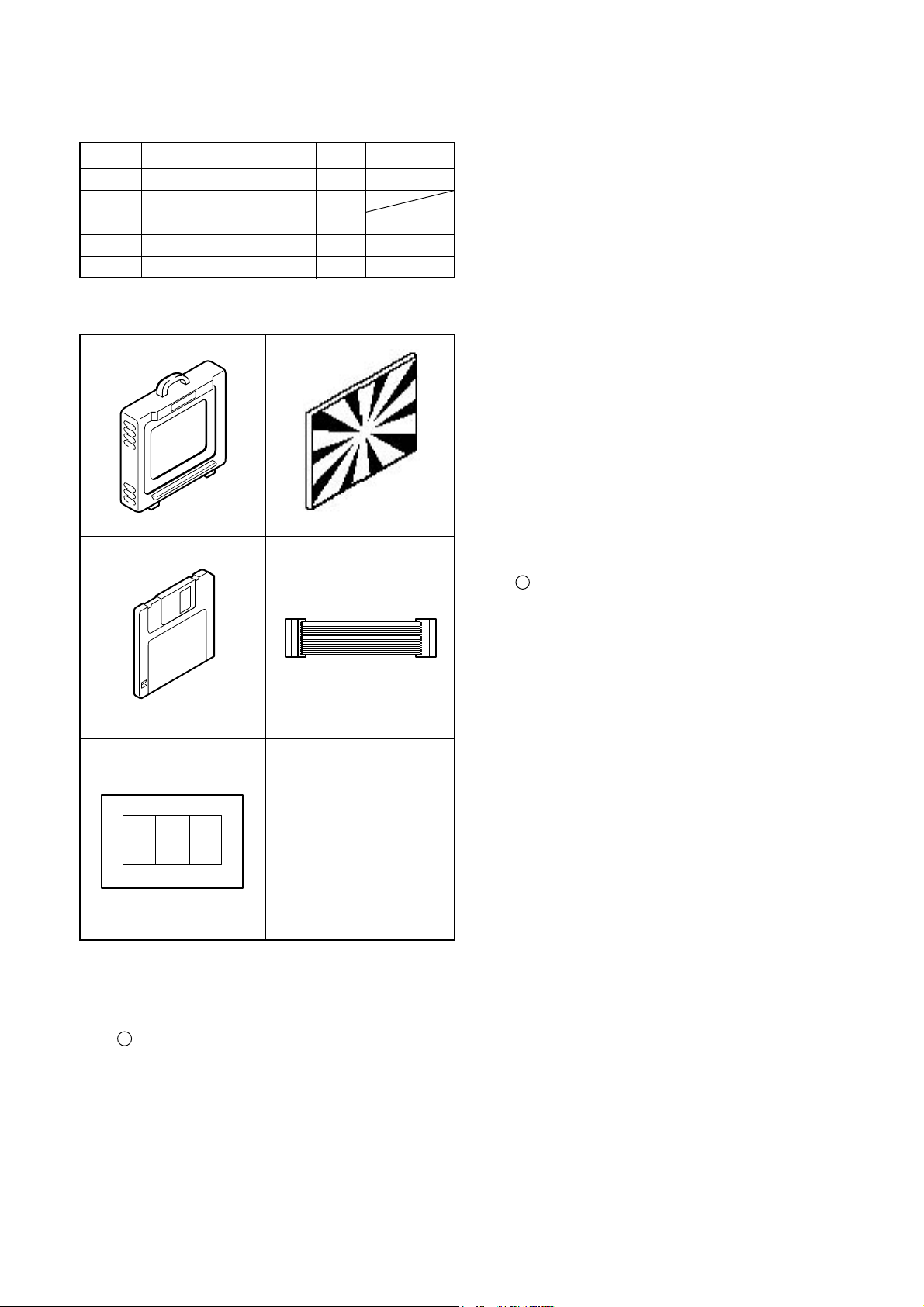
[ 1 ] Table for Servicing Tools
Ref. No. Name
J-1
J-2
J-3
J-4
J-5
Note: J-1 color viewer is 100 - 110 VAC only.
Color viewer 5,100 K
Siemens star chart
Calibration software
Extension cord
Chart for color adjustment
Qt’y
1
1
1
1
1
J-1 J-2
J-3
J-4
C. ADJUSTMENT METHOD C-990ZOOM/D-490ZOOM
[ 3 ] Adjustment Items and Order
1. IC501 Oscillation Frequency Adjustment
Part code
VJ8-0007
VJ8-0167
VJ8-0157
VJ8-0155
2. 5.0 V (A) Voltage Adjustment
3. 7.5 V (L) Voltage Adjustment 1
4. 7.5 V (L) Voltage Adjustment 2
5. AWB Adjustment
6. Color Matrix Adjustment
7. Lens Adjustment
8. CCD Defect Detect Adjustment
9. LCD Panel Adjustment
9-1. LCD H AFC Adjustment
9-2. LCD RGB Offset Adjustment
9-3. LCD Gain Adjustment
9-4. LCD Blue Brightness Adjustment
9-5. LCD Red Brightness Adjustment
9-6. LCD VcomPP Adjustment
Note:
1. If the lens, CCD, optical filter, board, changing the part
and disassemble around the lens in item 5-8 replace, it is
necessary to adjust again. 5-8 adjustments should be carried out in sequence.
[ 4 ] Setup
1. System requirements
Windows 95 or 98
IBM R -compatible PC with 486 or higher processor
CD-ROM drive
3.5-inch high-density diskette drive
Serial port with standard RS-232C interface
8 MB RAM
Hard disk drive with at least 15 MB available
VGA or SVGA monitor with at least 256-color display
J-5
3-2. Equipment
1. Oscilloscope
2. Digital voltmeter
3. AC adaptor
4. IBM R -compatible PC
5. DC regulated power supply
2. Installing calibration software
1. Insert the calibration software installation diskette into your
diskette drive.
2. Open Explorer.
3. Copy the DSC Cal folder on the floppy disk in the FD drive
to a folder on the hard disk.
4. Create a shortcut for the file DscCal_v123c.exe by drag-
ging and dropping it from the copied DscCal folder to the
Desktop or to another folder.
5. Right-click the shortcut icon to specify the command line
options.
6. Click Properties, and then click the Shortcut tab. Type a
space and then the numeral “3” (in single-byte charac
ters) at the end of the link destination. (*****.exe 3)
7. Click the OK button in the dialog box to finish.
3. Color Viewer
Turn on the switch and wait for 30 minutes for aging to take
place before using Color Pure.
C-2 Ver.2SERVER_DIS
Page 4
C. ADJUSTMENT METHODC-990ZOOM/D-490ZOOM
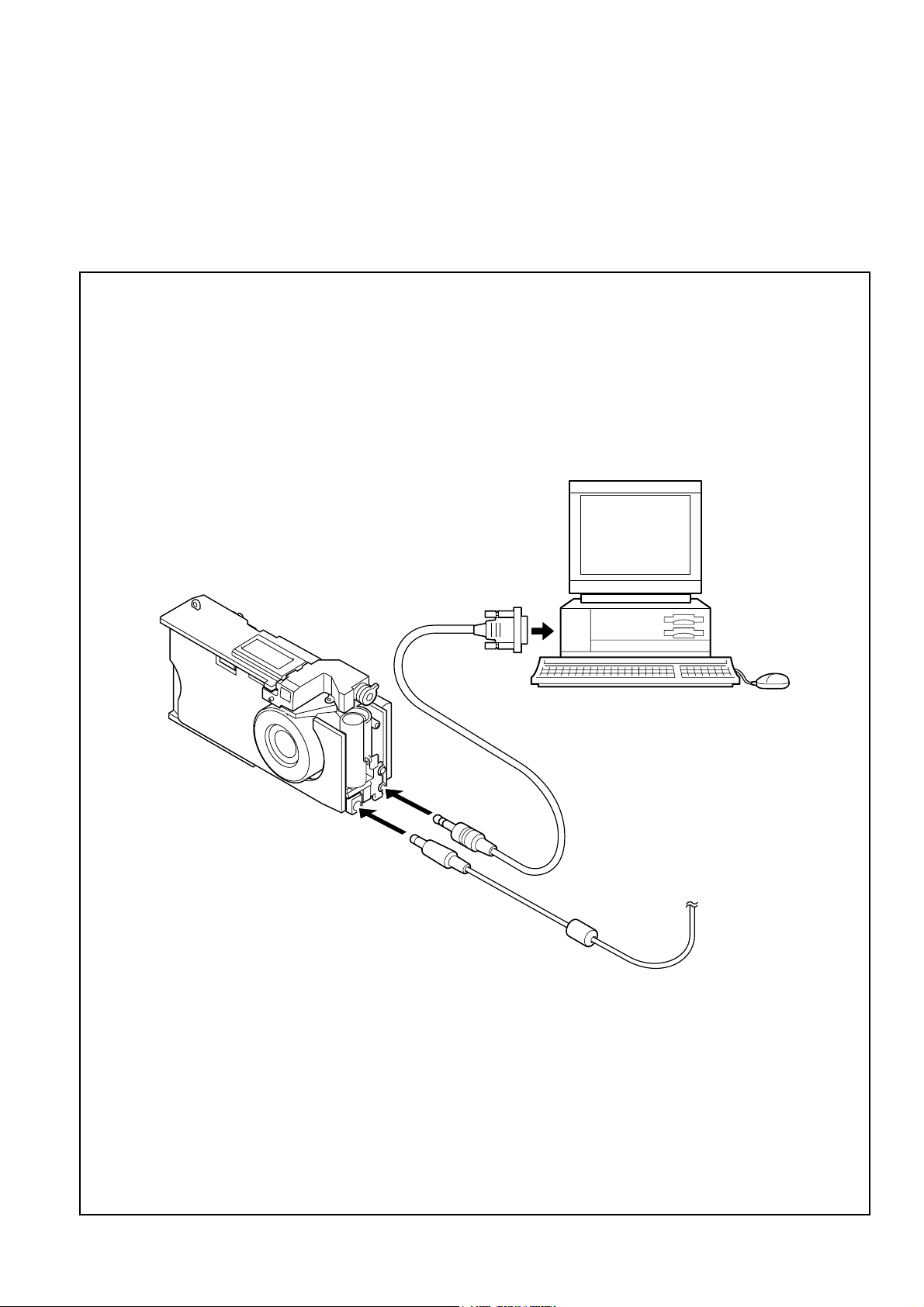
[ 5 ] Connecting the camera to the computer
1. Turn off both camera and computer.
2. Locate the port cover on the side of the camera. Press on the arrows and slide the cover down to open it.
3. Line up the arrow on the cable connector with the notch on the camera's serial port. Insert the connector.
4. Locate a serial port on the back of your computer. You may have two serial ports labeled COM1 and COM2, or the ports may
be labeled with icons. If you have two serial ports available, use port 1 to connect your camera.
5. Line up the serial connector on the cable with one of the serial ports on your computer, and insert the connector.
6. Turn on the camera and your computer system.
To COM1 or COM2 serial port
Serial cable
AC adaptor
C-3Ver.2 SERVER_DIS
Page 5
[ 6 ] Adjust Specifications
[ST1 board (Side B)]
C. ADJUSTMENT METHOD C-990ZOOM/D-490ZOOM
Adjustment method:
1. Adjust with VR503 to 7.50 ± 0.10 V.
4. 7.5 V (L) Voltage Adjustment 2
Note:
Voltage adjustment is necessary to repair in the ST1 board
and replace the parts.
Preparation:
1. Short Pins 1 and 2 of the S1401 card switch on the ST1
circuit board.
2. Connect the ST1 board and the CA1 board with two
extension cords.
3. Connect LCD panel.
4. Insert the card.
5. Turn on the power switch, and then set the camera mode.
6. Turn on the LCD monitor switch.
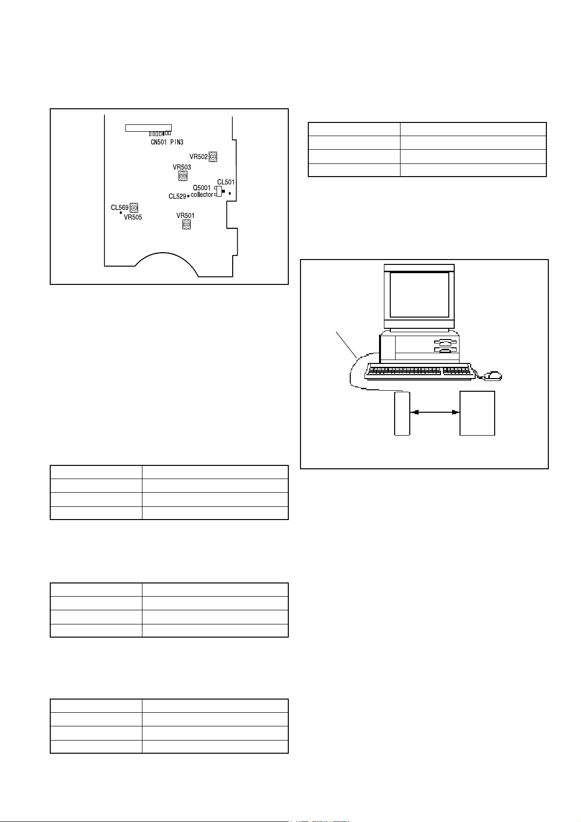
1. IC501 Oscillation Frequency Adjustment
Measuring Point
Measuring Equipment
ADJ. Location
ADJ. Value
CL569
Digital voltmeter
VR505
7.50 ± 0.10 V
Adjustment method:
1. Because the voltage is 8.7 V for the first second after
turing on, turn VR505 to adjust the voltage to
7.50 ± 0.10 V after 1 second has passed.
5. AWB Adjustment
Serial cable
Camera
0-18cm
All wite pattern
Color view (5,100K)
Measuring Point
Measuring Equipment
ADJ. Location
ADJ. Value
Q5001 Collector (CL501)
Frequency counter
VR501
200 ± 1 kHz
Adjustment method:
1. Adjust with VR501 to 200 ± 1 kHz.
2. 5.0 V (A) Voltage Adjustment
Measuring Point
Measuring Equipment
ADJ. Location
ADJ. Value
Adjustment method:
1. Adjust with VR502 to 5.03 ± 0.05 V.
CL529
Digital voltmeter
VR502
5.03 ± 0.05 V
3. 7.5 V (L) Voltage Adjustment 1
Measuring Point
Measuring Equipment
ADJ. Location
ADJ. Value
CN501 PIN3
Digital voltmeter
VR503
7.50 ± 0.10 V
Preparation:
POWER switch: ON
Adjusting method:
1. When setting the camera in place, set it to an angle so that
nothing appears in any part of the color viewer except the
white section. (Do not enter any light.)
2. Double-click on the DscCalDi123c.
3. Click the AWB, and click the Yes.
4. AWB adjustment value will appear on the screen.
5. Click the OK.
C-4 Ver.2SERVER_DIS
Page 6
6. Color Matrix Adjustment
Serial cable
C. ADJUSTMENT METHODC-990ZOOM/D-490ZOOM
Adjustment method:
1. Set the siemens star chart 150 cm ± 3 cm so that it becomes center of the screen.
2. Double-click on the DscCalDi123c.
3. Click the Focus, and Click the Yes.
4. Lens adjustment value will appear on the screen.
5. Click the OK.
8. CCD Defect Detect Adjustment
Adjustment method:
1. Double-click on the DscCalDi123c.
2. Select the Test “CCD Defect “,and then the adjustment starts.
3. After adjustment, OK will appear on the screen.
4. Click the OK.
Camera
15cm±1cm
All wite pattern Color
view (5,100K) and
color matrix adjustment chart
Preparation:
POWER switch: ON
Adjustment method:
1. Set the color adjustment chart to the color viewer.
(Do not enter any light.)
2. Set the color adjustment chart so that it becomes center of
the screen.
3. Double-click on the DscCalDi123c.
4. Click the UV Matrix adjustment values will appear on the
screen.
6. Click the OK.
7. Lens Adjustment
Serial cable
9. LCD Panel Adjustment
[CA1 board (Side B)]
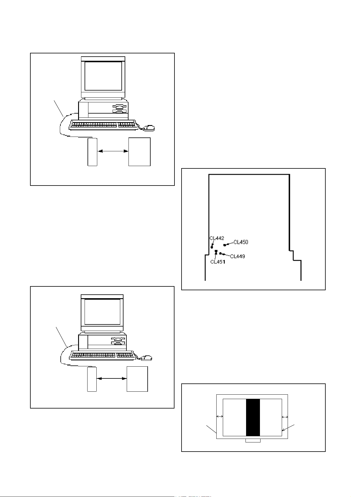
9-1. LCD H AFC Adjustment
Preparation:
POWER switch: ON
Adjusting method:
1. Double-click the DscCalDi123c shortcut icon.
2. Select LCD3 on the “LCD Type”.
3. Select 0 on the LCD “H_AFC”.
4. While watching the LCD monitor, adjust H_AFC so that the
edge of the LCD adjustment frame are the same distance
from the left and right edge of the LCD screen. (A = B)
Camera
150cm ± 3cm
Siemens stra chartt
Preparation:
POWER switch: ON
Adjustment condition:
Siemens star chart (A3)
Fluorescent light illumination with no flicker (incandescent light
cannot be used.)
Illumination above the subject should be 400 lux +/-10%.
LCD
adjustment
B
frame
LCD screen
A
FPC
C-5Ver.2 SERVER_DIS
Page 7

C. ADJUSTMENT METHOD C-990ZOOM/D-490ZOOM
9-2. LCD RGB Offset Adjustment
Adjusting method:
1. Adjust LCD “RGB offset”so that the amplitude of the CL450
waveform is 3.0 V ± 0.1 Vp-p.
3.0 V
± 0.1 Vp-p
9-5. LCD Red Brightness Adjustment
Adjusting method:
1. Adjust LCD “R Bright” so that the amplitude of the CL449
waveform is (VG-0.15) ±0.05 Vp-p with respect to the
CL450 (VG) waveform.
Note:
9-2. LCD RGB Offset adjustment and 9-3. LCD Gain adjustment should always be carried out first.
CL450 waveform
9-3. LCD Gain Adjustment
Adjusting method:
1. Adjust LCD “Gain” so that the amplitude of the CL450 waveform is 1.6 V ±0.1 Vp-p.
Note:
9-2. LCD RGB Offset adjustment should always be carried
out first.
1.6 V
±0.1 Vp-p
CL450 waveform
9-4. LCD Blue Brightness Adjustment
Adjusting method:
1. Adjust LCD “B Bright” so that the amplitude of the CL451
waveform is (VG+0.1) ±0.05 Vp-p with respect to the
CL450 (VG) waveform.
Note:
9-2. LCD RGB Offset adjustment and 9-3. LCD Gain adjustment should always be carried out first.
VG
CL450 waveform
a) VG>0.15 V
(VG-0.15)
±0.05 Vp-p
CL449 waveform
b) VG<0.15 V
(VG-0.15)
±0.05 Vp-p
CL449 waveform
9-6. LCD VcomPP Adjustment
Adjusting method:
1. Adjust LCD “VCOMPP”so that the amplitude of the CL442
waveform is 5.0 V ± 0.25 Vp-p.
CL450 waveform
CL451 waveform
VG
(VG+0.1)
±0.05 Vp-p
5.0 V
± 0.25 Vp-p
CL442 waveform
C-6 Ver.2SERVER_DIS
Page 8

C. ADJUSTMENT METHODC-990ZOOM/D-490ZOOM
[7] Adjustment Items
Changed repair parts
Adjustment items
1 IC501 Oscillation Frequency Adjustment
2 5.0V(A) Voltage Adjustment
3 7.5V(L) Voltage Adjustment 1
4 7.5V(L) Voltage Adjustment 1
5 AWB Adjustment
6 Color Matrix Adjustmen
7 Lens Adjustment
8 CCD Defect Detect Adjustment
9-1 LCD H AFC Adjustment
9-2 LCD RGB Offset Adjustm ent
9-3 LCD Gain Adjustment
9-4 LCD Blue Brightness Adjustment
9-5 LCD Red Brightness Adjustment
9-6 LCD VcomPP Adjustment
*1) There is no need that you adjust the provided ST1when changing it without changing the parts of component level.
CCD LENS ST1 CA1
※1○
※1○
※1○
※1○
○○ ○
○○ ○
○○ ○
○○ ○
○
○
○
○
○
○
C-7Ver.2 SERVER_DIS
Page 9

C. ADJUSTMENT METHOD
C-990ZOOM/D-490ZOOM
C-8 Ver. 2
Page 10

C. ADJUSTMENT METHOD
C-990ZS/C-990ZOOM2/D-490ZOOM2
[1] Table for Servicing Tools
Ref. No. Name
J-1
J-2
J-3
J-4
J-5
Note: J-1 color viewer is 100 - 110 VAC only.
Color viewer 5,100 K
Siemens star chart
Calibration software
Extension cord
Chart for color adjustment
Number
1
1
1
1
1
J-1 J-2
J-3
J-4
Part code
VJ8-0007
VJ8-0167
VJ8-0157
VJ8-0155
[3] Adjustment Items and Order
1. IC501 Oscillation Frequency Adjustment
2. 5.0 V (A) Voltage Adjustment
3. 12.4 V (L) Voltage Adjustment
4. 9.0 V (L) Voltage Adjustment
5. AWB Adjustment
6. Color Matrix Adjustment
7. Lens Adjustment
8. CCD Defect Detect Adjustment
9. LCD Panel Adjustment
9-1. LCD H AFC Adjustment
9-2. LCD RGB Offset Adjustment
9-3. LCD Gain Adjustment
9-4. LCD Blue Brightness Adjustment
9-5. LCD Red Brightness Adjustment
Note:
1. If the lens, CCD, optical filter, board, changing the part
and disassemble around the lens in item 5-8 replace, it is
necessary to adjust again. 5-8 adjustments should be carried out in sequence.
[4] Setup
1. System requirements
Windows 95 or 98
IBM R -compatible PC with 486 or higher processor
CD-ROM drive
3.5-inch high-density diskette drive
Serial port with standard RS-232C interface
8 MB RAM
Hard disk drive with at least 15 MB available
VGA or SVGA monitor with at least 256-color display
J-5
[2] Equipment
1. Oscilloscope
2. Digital voltmeter
3. AC adaptor
4. IBM R -compatible PC
5. DC regulated power supply
2. Color Viewer
Turn on the switch and wait for 30 minutes for aging to take
place before using Color Pure.
C-9 Ver.2SERVER_DIS
Page 11

C-990ZS/C-990ZOOM2/D-490ZOOM2
C. ADJUSTMENT METHOD
[5] Connecting the camera to the computer
1. Turn off both camera and computer.
2. Locate the port cover on the side of the camera. Press on the arrows and slide the cover down to open it.
3. Line up the arrow on the cable connector with the notch on the camera's serial port. Insert the connector.
4. Locate a serial port on the back of your computer. You may have two serial ports labeled COM1 and COM2, or the ports
may be labeled with icons. If you have two serial ports available, use port 1 to connect your camera.
5. Line up the serial connector on the cable with one of the serial ports on your computer, and insert the connector.
6. Turn on the camera and your computer system.
To COM1 or COM2 serial port
Serial cable
AC adaptor
C-10Ver.2 SERVER_DIS
Page 12

C. ADJUSTMENT METHOD
[6] Adjust Specifications
[ST1 board (Side B)]
CL526
(Side A)
VR503
VR502
CL501
CL569
VR505
CL529
VR501
Q5001
collector
Note:
Voltage adjustment is necessary to repair in the ST1 board
and replace the parts.
Preparation:
1. Short Pins 1 and 2 of the S1401 card switch on the ST1
circuit board.
2. Connect the ST1 board and the CA1 board with extension cord.
3. Connect LCD panel.
4. Insert the card.
5. Turn on the power switch, and then set the camera mode.
6. Turn on the LCD monitor switch.
1. IC501 Oscillation Frequency Adjustment
Measuring Point
Measuring Equipment
ADJ. Location
ADJ. Value
Adjustment method:
1. Adjust with VR501 to 200 ± 1 kHz.
Q5001 Collector (CL501)
Frequency counter
VR501
200 ± 1 kHz
2. 5.0 V (A) Voltage Adjustment
C-990ZS/C-990ZOOM2/D-490ZOOM2
Adjustment method:
1. Adjust with VR503 to 12.40 ± 0.05 V.
4. 9.0 V (L) Voltage Adjustment
Measuring Point
Measuring Equipment
ADJ. Location
ADJ. Value
Adjustment method:
1. Adjust with VR505 to 9.00 ± 0.05 V.
CL569
Digital voltmeter
VR505
9.00 ± 0.05 V
5. AWB Adjustment
Serial cable
Camera
Preparation:
POWER switch: ON
Adjusting method:
1. When setting the camera in place, set it to an angle so
that nothing appears in any part of the color viewer except the white section. (Do not enter any light.)
2. Double-click on the DscCalDi125.
3. Click the AWB, and click the Yes.
4. AWB adjustment value will appear on the screen.
5. Click the OK.
0-18cm
All wite pattern
Color view (5,100K)
Measuring Point
Measuring Equipment
ADJ. Location
ADJ. Value
CL529
Digital voltmeter
VR502
5.03 ± 0.05 V
Adjustment method:
1. Adjust with VR502 to 5.03 ± 0.05 V.
3. 12.4 V (L) Voltage Adjustment
Measuring Point
Measuring Equipment
ADJ. Location
ADJ. Value
CL562
Digital voltmeter
VR503
12.40 ± 0.05 V
C-11 Ver.2SERVER_DIS
Page 13

C-990ZS/C-990ZOOM2/D-490ZOOM2
C. ADJUSTMENT METHOD
6. Color Matrix Adjustment
Serial cable
Camera
15cm±1cm
All wite pattern Color
view (5,100K) and
color matrix adjustment chart
Preparation:
POWER switch: ON
Adjustment method:
1. Set the color adjustment chart to the color viewer.
(Do not enter any light.)
2. Set the color adjustment chart so that it becomes center
of the screen.
3. Double-click on the DscCalDi125.
4. Click the UV Matrix adjustment values will appear on the
screen.
6. Click the OK.
Adjustment method:
1. Set the siemens star chart 150 cm ± 3 cm so that it becomes center of the screen.
2. Double-click on the DscCalDi125.
3. Click the Focus, and Click the Yes.
4. Lens adjustment value will appear on the screen.
5. Click the OK.
8. CCD Defect Detect Adjustment
Adjustment method:
1. Double-click on the DscCalDi125.
2.Select “CCD Defect” on the LCD “Test”, and click the
“Yes”.
3. After the adjustment is completed, OK will display.
4. Click the OK.
9. LCD Panel Adjustment
[CA1 board (Side B)]
CL483
CL481
CL482
7. Lens Adjustment
Serial cable
Camera
150cm ± 3cm
Siemens stra chartt
Preparation:
POWER switch: ON
Adjustment condition:
Siemens star chart (A3)
Fluorescent light illumination with no flicker (incandescent
light cannot be used.)
Illumination above the subject should be 400 lux ± 10%.
9-1. LCD H AFC Adjustment
Preparation:
POWER switch: ON
Adjusting method:
1. Double-click on the DscCalDi125.
2. Select 0 on the LCD “H AFC”.
3. While watching the LCD monitor, adjust “H AFC” so that
the edge of the LCD adjustment frame are the same distance from the left and right edge of the LCD screen. (A
=B)
LCD
LCD screen
A
adjustment
B
frame
FPC
9-2. LCD RGB Offset Adjustment
Adjusting method:
1. Adjust LCD “RGB Offset” so that the amplitude of the
CL483 waveform is 6.8 V ± 0.15 Vp-p.
C-12Ver.2 SERVER_DIS
Page 14

C. ADJUSTMENT METHOD
C-990ZS/C-990ZOOM2/D-490ZOOM2
6.8 V±
0.15 Vp-p
CL483 waveform
9-3. LCD Gain Adjustment
Adjusting method:
1. Adjust LCD “Gain” so that the amplitude of the CL483
waveform is 3.9 V ± 0.1 Vp-p.
Note:
9-2. LCD RGB Offset adjustment should always be carried
out first.
3.9 V±
0.1 Vp-p
CL483 waveform
VG
CL483 waveform
VG±0.1 Vp-p
CL481 waveform
9-5. LCD Red Brightness Adjustment
Adjusting method:
1. Adjust LCD “R Bright” so that the amplitude of the CL482
waveform is VG ± 0.1 Vp-p with respect to the CL483
(VG) waveform.
Note:
9-2. LCD RGB Offset adjustment and 9-3. LCD Gain adjustment have done.
9-4. LCD Blue Brightness Adjustment
Adjusting method:
1. Adjust LCD “B Bright” so that the amplitude of the CL481
waveform is VG ± 0.1 Vp-p with respect to the CL483
(VG) waveform.
Note:
9-2. LCD RGB Offset adjustment and 9-3. LCD Gain adjustment should always be carried out first.
VG
CL483 waveform
VG±0.1 Vp-p
CL482 waveform
C-13 Ver.2SERVER_DIS
Page 15

C-990ZS/C-990ZOOM2/D-490ZOOM2
C. ADJUSTMENT METHOD
[7] Adjustment Items
Changed repair parts
Adjustment items
1 IC501 Oscillation Frequency Adjustment
2 5.0V(A) Voltage Adjustment
3 12.4V(L) Voltage Adjustment
4 9.0V(L) Voltage Adjustment
5 AWB Adjustment
6 Color Matrix Adjustmen
7 Lens Adjustment
8 CCD Defect Detect Adjustment
9-1 LCD H AFC Adjustment
9-2 LCD RGB Offset Adjustm ent
9-3 LCD Gain Adjustment
9-4 LCD Blue Brightness Adjustment
9-5 LCD Red Brightness Adjustment
*1) There is no need that you adjust the provided ST1when changing it without changing the parts of component level.
CCD LENS ST1 CA1
※1○
※1○
※1○
※1○
○○ ○
○○ ○
○○ ○
○○ ○
○
○
○
○
○
C-14Ver.2 SERVER_DIS
Page 16

CHECKING OF LENS UNIT
1. Check Item
1)Backlash Pulse of LD
2)LD ERROR Pulse
3)Basklash Pulse of ZOOM
4)ZOOM ERROR Pulse
2. Tools
Part No.
1
2
3
4
5
KC0331
KC0333
KC0338
FPC-Adaptor
FPC-Adaptor
C.ADJUSTMENT METHOD
Description
Lens Checker LCK1
Connector Cable P4
Clip Connector 17
12-PINS for K-FPC
10-PINS for S-FPC
Q’ty
1
1
2
1
1
FPC-Adaptor 12
PINS for K-FPC
FPC-Adaptor 10
PINS for S-FPC
The last 2 digits are mean-
ing the number of Pin.
080-10
3. Checking Prosedure
Fi x 2 FPC-Adaptors (10 and 12 PINS) to ClipConnector
17.
Connect Connector Cable P4, Clip Connector 17
and Lens Checker LCK-1
1) AUTO
I. Tum on Lens Checker LCK-1
Ex.) 080-10 :10PINS
Lens Checker LCK-1
Connector Cable P4
Initial Setting
II. Set AUTO / MANU SW at AUTO
III.Set Dial SW at 0
IV. Set CW / CCW SW at CW
LCK-1 Ver.1 0 Auto
PUSH START SW
(0 : Number of Dial SW 0-5)
V. Connect the both FPCs (K-FPC and S-FPC) to
Clip Connectors. Hold a lens unit by hand, and keep
it horizontally.
VI. Push START SW. (More than 0.2 sec.)
LCK-1 Ver.1 0 Auto
ZOOM RESET
Clip Connector 17
C-15Ver. 2/Rev.5
Page 17

C.ADJUSTMENT METHOD
When an error occurs, an error is indicated, and it stops.
LCK-1 Ver.1 0 Auto
LD RESET
LCK-1 Ver.1 0 Auto
LD BACKLASH CHK
LB*
* is BACKLASH PULSE of LD
LCK-1 Ver.1 0 Auto
LD D CHK
LB1 D *
* is LD ERROR PULSE
LCK-1 Ver.1 0 Auto
ZOOM BACKLASH CHK
LB1 D1 ZB *
* is BACKLASH PLUSE of ZOOM
In case of GOOD
LCK-1 Ver.1 0 Auto
PUSH START SW
LB1 D1 ZB1 D12
GOOD
In case of NG :
LCK-1 Ver.1 0 Auto
PUSH START SW
LB D6
NO GOOD ZM D Err
ERROR is indicated
(The indication which isn’t being explained is the condition
of PR and PI.)
When CW/CCW SW is set at CCW, the automatic check of
the motor chosen with a LD/ZOOM SW is done.
2) Manual
I. Set AUTO/MANU SW at MANU
LCK-1 Ver.1 0 Manu
LD CW
LCK-1 Ver.1 0 Auto
ZOOM D CHK
LB1 D1 ZB1 D * *
* * is ZOOM ERROR PULSE (ZOOM AREA : SET-UP AREA)
The contents chosen with the LD/ZOOM SW and the CW/
CCW SW indicated in LCD.
II. Push START SW (More than 0.2 sec.)
LCK- Ver.1 0 Manu
LD CW
MOVE
When a motor works, “MOVE” is indicated in LCD.
C-16 Ver. 2/Rev.5
Page 18

C.ADJUSTMENT METHOD
LD Motor
When PI signal 500 pulses (500pps) are changed,LD motor
stops
CW : Turn Out CCW : Tum In
ZOOM Motor
When PI signal 2200 pulses (300pps) are changed, ZOOM
motor stops
CW : W to T CCW : T to W
4. Others
Turn off LCK-1 promptly if something is wrong.
5, ERROR Indication
PI, PR Err : PI or PR Pulse does not change.
LD BK Err : LD BACKLASH PULSE is out of standard.
LD D Err : LD Pulse Error
ZD BK Err : ZOOM BACKLASH PULSE is out of
standard
ZD D Err : ZOOM Pulse Error
C-17Ver. 2/Rev.5
 Loading...