

Page 1

B. DISASSEMBL Y AND ASSEMBLY PROCEDURE
C-4040ZOOM
B. DISASSEMBLY AND ASSEMBLY
PROCEDURE
[1] REMOVAL OF CABINET TOP ASSEMBLY, CABINET FRONT ASSEMBLY
AND CABINET BACK ASSEMBLY ....................................................................B-2
[2] REMOVAL OF LENS VF AND FLEXIBLY PWB.....................................................B-3
[3] REMOVAL OF LENS ASSEMBLY AND CA1 BOARD ...........................................B-4
[4] REMOVAL OF SY1 BOARD, CA2 BOARD AND ST1 BOARD ..............................B-4
[5] BOARD LOCATION ................................................................................................B-5
B-1 Ver.1
Page 2
B. DISASSEMBLY AND ASSEMBLY PROCEDURE C-4040ZOOM
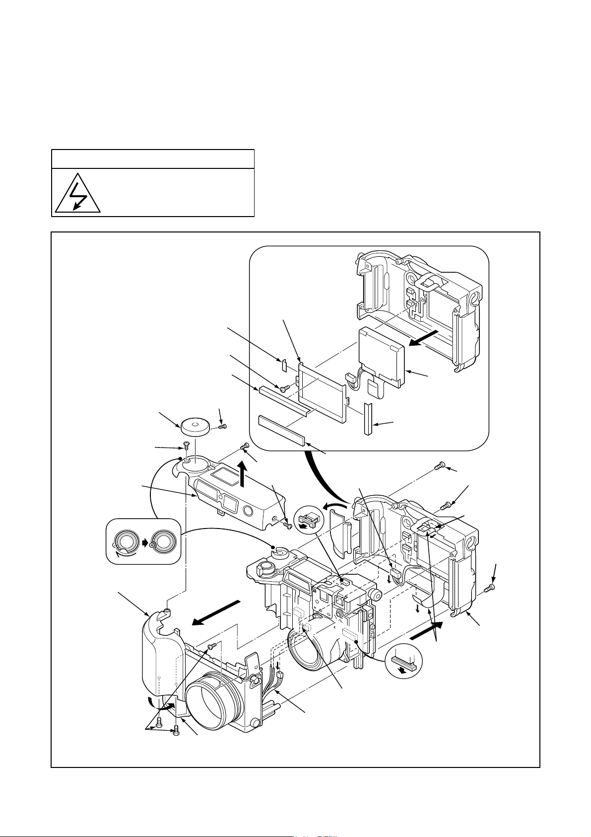
[1] REMOVAL OF CABINET TOP ASSEMBLY, CABINET FRONT ASSEMBLY AND CABINET BACK ASSEMBLY
Disassembly perform as follows and assembly perform by reversing the disassembly steps.
Be sure to discharge the main capacitor, then continue to disassembling.
! Beware of electric shock
Danger of electric shock.
Use a discharging tool to remove
the electrical charge before working.
When assembling, attach the
spacers to the holder monitor
in the order 20, 19, 18 and 21.
22. Holder monitor
20. Spacer monitor
light C
17. Screw 1.7 x 4
3. Cover dial
4. Screw
1.7 x 3.5
5. Cabinet top
10. Cabinet front
18. Spacer monitor
light
2. Screw
1.4 x 4
1. Two screws
1.7 x 3.5
8. Cover
card
21. Spacer shield
monitor
16. Connector
23. LCD
19. Spacer monitor
light B
9. Two screws
1.7 x 8
13. FPC
9. Screw
1.7 x 4
14. Cabinet back
15. FPC
7. Three screws
1.7 x 4
11. Discharge both ends of C5412.
(ST1 board side A)
12. Connector
6. Open the cover battery.
B-2 Ver. 1
Page 3

B. DISASSEMBLY AND ASSEMBLY PROCEDUREC-4040ZOOM
[2] REMOVAL OF LENS VF AND FLEXIBL E PWB
6. Screw 1.7 x 4
7. Holder
mode
5. Spacer
chassis
4. Spacer
sheet
1. LCD
2. Screw 1.7 x 4
3. Reflector
9. Two screws 1.7 x 4
12. FPC
8. Screw 1.4 x 3.5
11. Flexible PWB
13. Two screws
1.7 x 4
10. Connector
14. Lens VF
17. Connector
When installing
1. Gear 1 should be positioned correctly.
2. The lens VF should be in the extended position.
16. Holder LED
15. Screw 1.7 x 4
18. Microphone
B-3 Ver. 1
Page 4

B. DISASSEMBLY AND ASSEMBLY PROCEDURE C-4040ZOOM
[3] REMOVAL OF LENS ASSEMBLY AND CA1 BOARD
When assembling, the lens VF and the
gear 1 should be positioned correctly before installing the lens assembly.
6. CA1 board
5. Two screws
2 x 6
B
A
B
C
3. Two FPCs
A
Lens
CCD
4. PFC
Install so that it is
perpendicular.
2. Screw 1.7 x 6
1. Three screws 1.7 x 4
[4] REMOVAL OF SY1 BOARD, CA2 BOARD AND ST1 BOARD
5. Holder BRKT SY
4. SY1 board
6. Two screws
1.7 x 4
7. Connector
C
1. Screw 1.7 x 4
3. Connector
2. Screw
1.7 x 4
10. Connector
E
E
D
8. CA2 circuit
D
11. ST1 board
9. Two screws
1.7 x 4
B-4 Ver. 1
Page 5

[5] BOARD LOCATION
B. DISASSEMBLY AND ASSEMBLY PROCEDUREC-4040ZOOM
SY1 board
CA2 board
ST1 board
CA1 board
B-5 Ver. 1
 Loading...