

Page 1

C. ADJUSTMENT METHOD
C-300 ZOOM/D-550 ZOOM
C. ADJUSTMENT METHOD
[1] TABLE FOR SERVICING TOOLS .......................................................................... C-2
[2] EQUIPMENT ........................................................................................................... C-2
[3] ADJUSTMENT ITEMS AND ORDER ..................................................................... C-2
[4] SETUP ....................................................................................................................C-2
[5] CONNECTING THE CAMERA TO THE COMPUTER ............................................ C-3
[6] USB STORAGE INFORMATION REGISTRATION ................................................. C-4
[7] ADJUST SPECIFICATIONS.................................................................................... C-4
1. IC501 OSCILLATION FREQUENCY ADJUSTMENT ...........................................C-4
2. 5.1 V (A) VOLTAGE ADJUSTMENT .....................................................................C-5
3. 12.0 (L) VOLTAGE ADJUSTMENT ........................................................................ C-5
4. LENS ADJUSTMENT ........................................................................................... C-5
5. AWB ADJUSTMENT ............................................................................................. C-5
6. CCD WHITE POINT DEFECT DETECT ADJUSTMENT ...................................... C-5
7. CCD BLACK POINT AND WHITE POINT DEFECT DETECT ADJUSTMENT ... C-6
8. LCD PANEL ADJUSTMENT ................................................................................ C-6
8-1 LCD RGB OFFSET ADJUSTMENT ............................................................ C-6
8-2 LCD GAIN ADJUSTMENT .......................................................................... C-6
8-3. LCD BLUE BRIGHTNESS ADJUSTMENT ...............................................C-7
8-4. LCD RED BRIGHTNESS ADJUSTMENT.................................................. C-7
8-5. LCD VCOM PP ADJUSTMENT .................................................................. C-7
[8] ADJUSTMENT ITEMS ............................................................................................C-8
SIMENS STAR CHART ................................................................................................... C-9
[9] VIEWER LUMINOSITY MEASUREMENT PROCEDURE .................................... C-10
CHECKING OF LENS UNIT .........................................................................................C-12
C-1 Ver.1/Rev.4
Page 2
C. ADJUSTMENT METHOD C-300 ZOOM / D-550 ZOOM
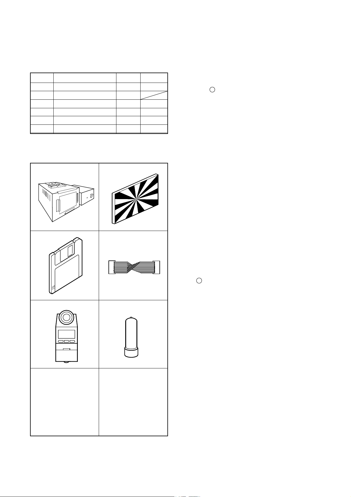
[1] T able for Servicing Tools
Ref. No. Name Part code
J-1
J-2
J-3
J-4
J-5 1
J-6
Note: J-1 color viewer is 100 ± 10 VAC only.
Pattern box (color viewer)
Siemens star chart
Calibration software
Extension cord
Chroma meter
Spare lump
Number
1
1
1
1
1
KC0336
VJ8-0189
VJ8-0180
KC0337
KC0339
J-1 J-2
J-3
J-4
[2] Equipment
1. Oscilloscope
2. Digital voltmeter
3. AC adaptor
4. PC (IBM R -compatible PC, Pentium processor, Window
98 or Me or 2000)
[3] Adjustment Items and Order
1. IC501 Oscillation Frequency Adjustment
2. 5.1 V (A) Voltage Adjustment
3. 12.0 V (L) Voltage Adjustment
4. Lens Adjustment
5. AWB Adjustment
6. CCD White Point Defect Detect Adjustment
7. CCD Black Point And White Point Defect Detect Adjust-
ment in Lighted
8. LCD Panel Adjustment
8-1. LCD RGB Offset Adjustment
8-2. LCD Gain Adjustment
8-3. LCD Blue Brightness Adjustment
8-4. LCD Red Brightness Adjustment
8-5. LCD VcomPP Adjustment
Note:
1. If the lens, CCD, board and changing the part in item 4-
7 replace, it is necessary to adjust again. 4-6 adjustments
other than these should be carried out in sequence. Item
7 adjustment should be carried out after item 5.
J-5
J-6
[4]. Setup
1. System requirements
Windows 98 or Me or 2000
IBM R -compatible PC with pentium processor
CD-ROM drive
3.5-inch high-density diskette drive
USB port
40 MB RAM
Hard disk drive with at least 15 MB available
VGA or SVGA monitor with at least 256-color display
2. Installing calibration software
1. Insert the calibration software installation diskette into
your diskette drive.
2. Open Explorer.
3. Copy the DscCalDI_128c folder on the floppy disk in the
FD drive to a folder on the hard disk.
3. Installing USB drive
Install the USB drive with camera or connection kit for PC.
4. Pattern box (color viewer)
Turn on the switch and wait for 30 minutes for aging to take
place before using Color Pure. It is used after adjusting the
chroma meter (KC0337) adjust color temperature to 3100
± 20 K and luminosity to 900 ± 20 cd/m
handling the lump and its circumference are high temperature during use and after power off for a while.
2
. Be careful of
C-2 Ver . 1/Rev .1
Page 3
C. ADJUSTMENT METHODC-300 ZOOM / D-550 ZOOM
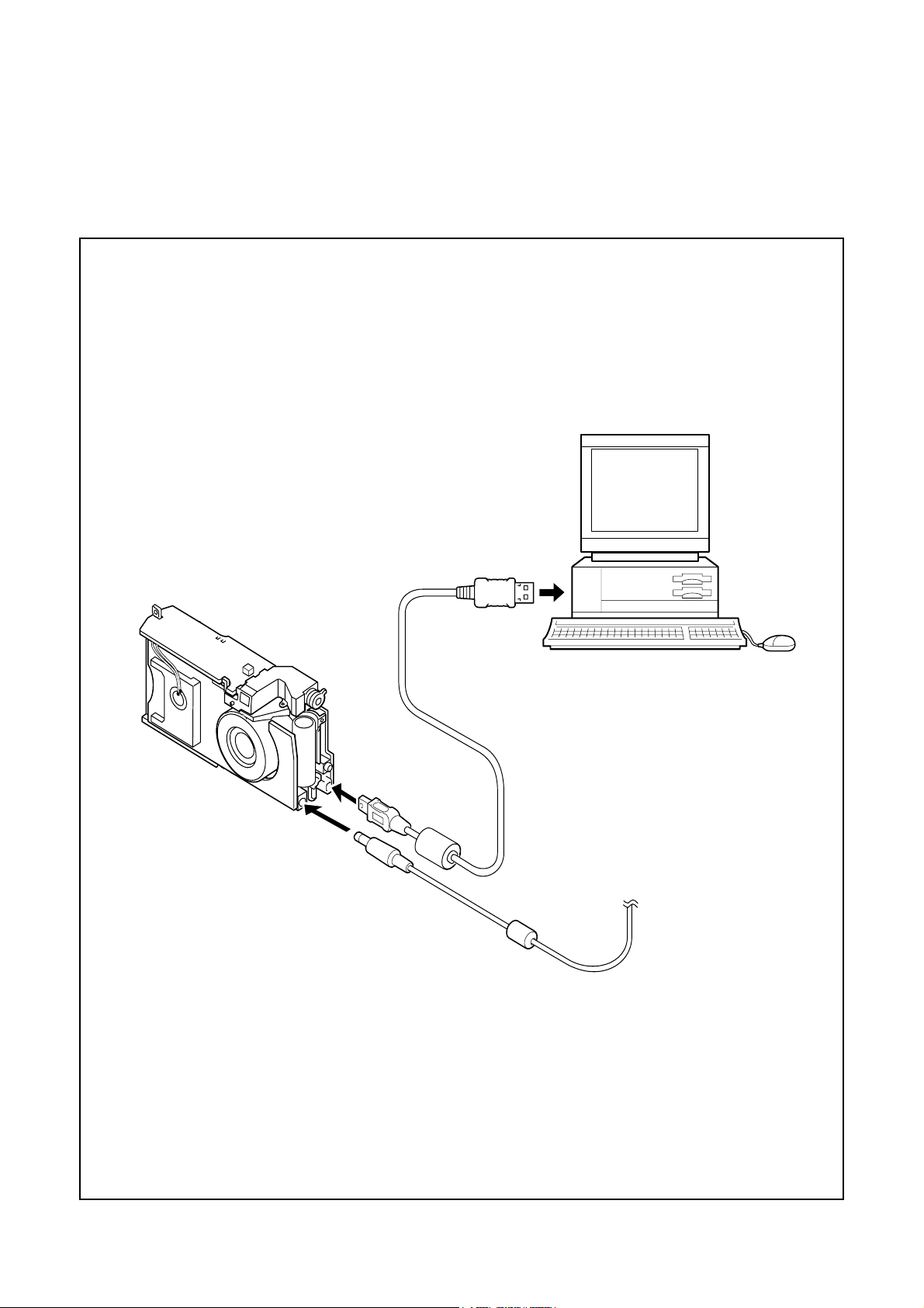
[5] Connecting the camera to the computer
1. Line up the arrow on the cable connector with the notch on the camera's USB port. Insert the connector.
2. Insert the SmartMedia in the camera.
3. Locate a USB port on your computer.
To USB port
Ver. 1
USB cable
AC adaptor
C-3
Page 4
C. ADJUSTMENT METHOD C-300 ZOOM / D-550 ZOOM
VR504
VR501
VR502
CL528
CL571
[6] USB Storage Information Registration
USB storage data is important for when the camera is connected to a computer via a USB connection.
If there are any errors in the USB storage data, or if it has
not been saved, the USB specification conditions will not be
satisfied, so always check and save the USB storage data.
Preparation:
POWER switch: ON
Adjustment method:
1. Connect the camera to a computer. (Refer to [5] Connecting the camera to the computer on the page C-3.)
2. Double-click on the DscCalDi128c.
3. Click on the Get button in the USB storage window and
check the USB storage data.
VID: OLYMPUS
PID: C-300Z/D-550Z
Serial:
Rev. : 1.00
4. Check the “Serial” in the above USB storage data. If the
displayed value is different from the serial number printed
on the base of the camera, enter the number on the
base of the camera. Then click the Set button.
5. Next, check VID, PID and Rev. entries in the USB storage data. If any of them are different from the values in
3. above, make the changes and then click the corresponding Set button.
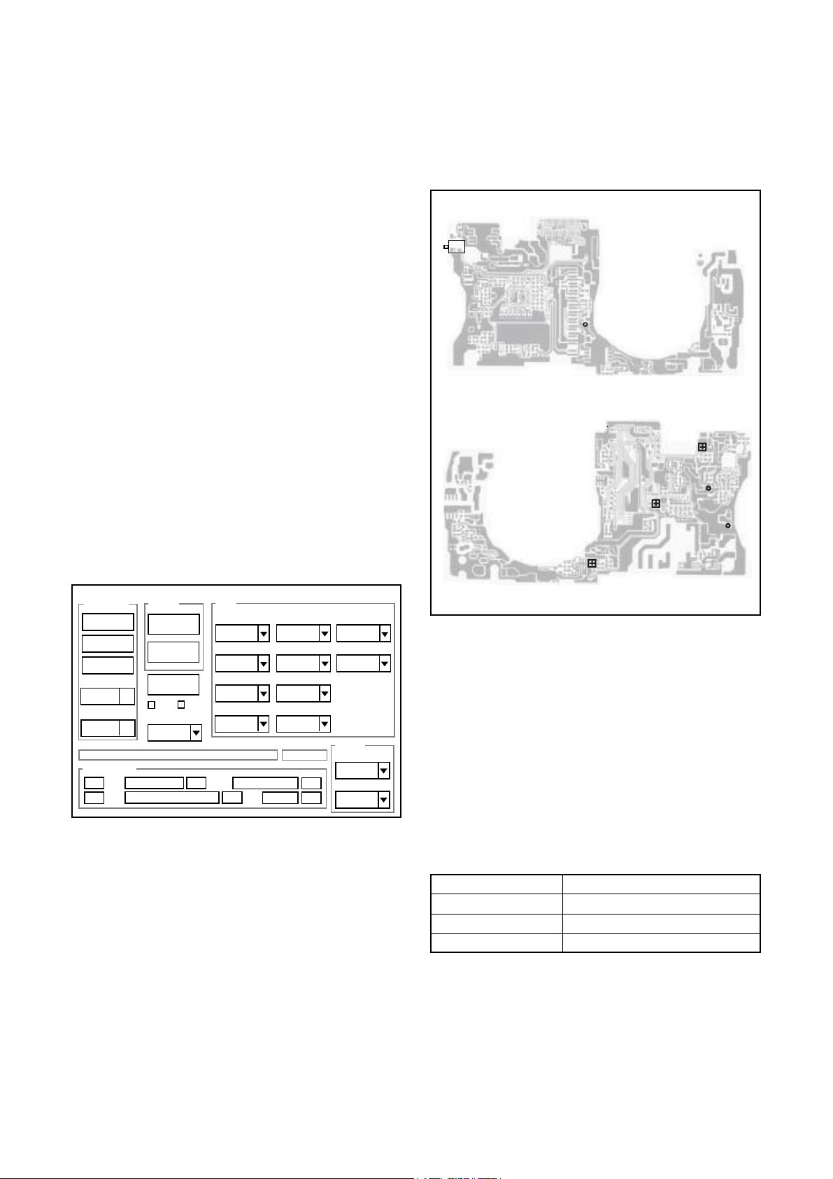
[7] Adjust Specifications
[ST1 board (Side B/A)]
S1401
CL558
Side A
Calibration
AWB
Focus
UV Matrix
Cal Mode
OK
Cal Data
OK
USB storage
VID
Get
PID
Set
Upload
Firmware
Image
Initialize
EVF
LCD Type
LCD
R Bright
RGB Offset
Tint
VCO
H AFC Test
Set
Serial
Set
Rev.
B Bright
Gain
Phase
Set
Set
VCOMDC
VCOMPP
Setting
Language
Video Mode
Side B
Note:
Voltage adjustment is necessary to repair in the ST1 board
and replace the parts.
Preparation:
1. Short Pins 1 and 2 of the S1401 card switch on the ST1
circuit board.
2. Connect the ST1 board and the SY1 board with extension cord (VJ8-0180).
3. Connect the lead wire of LCD backlight.
4. Insert the card.
5. Turn on the power switch, and then set the camera mode.
6. Turn on the LCD monitor switch.
1. IC501 Oscillation Frequency Adjustment
Measuring Point
Measuring Equipment
ADJ. Location
ADJ. Value
Adjustment method:
1. Adjust with VR501 to 504.0 ± 1 kHz.
CL571
Frequency counter
VR501
504.0 ± 1 kHz
C-4 Ver. 1
Page 5
C. ADJUSTMENT METHODC-300 ZOOM / D-550 ZOOM
2. 5.1 V (A) Voltage Adjustment
Measuring Point
Measuring Equipment
ADJ. Location
ADJ. Value
Adjustment method:
1. Adjust with VR502 to 5.10 ± 0.05 V.
CL528
Digital voltmeter
VR502
5.10 ± 0.05 V
3. 12.0 V (L) Voltage Adjustment
Measuring Point
Measuring Equipment
ADJ. Location
ADJ. Value
Adjustment method:
1.Adjust with VR504 to 12.0 ± 0.05 V.
CL558
Digital voltmeter
VR504
12.0 ± 0.05 V
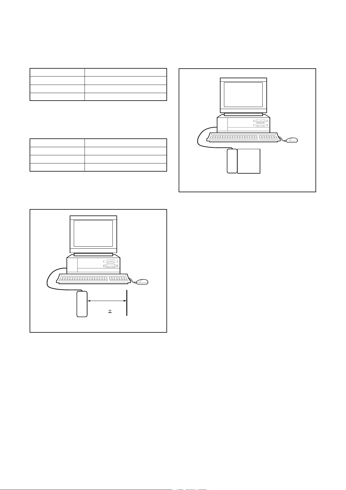
4. Lens Adjustment
5. AWB Adjustment
Camera
Pattern box
(color viewer)
Preparation:
POWER switch: ON
Setting of pattern box:
Color temperature: 3100 ± 20 (K)
Luminance: 900 ± 20 (cd/m
Adjusting method:
1. Set the camera 0 cm from the pattern box. (Do not enter
any light.)
2. Double-click on the DscCalDi128c.
3. Click the “AWB”, and click the “Yes”.
4. AWB adjustment value will appear on the screen.
5. Click the OK.
2
)
Camera
Approx.
150 cm 3 cm
Siemens
star chart
Preparation:
POWER switch: ON
Adjustment condition:
Siemens star chart (A3)
Fluorescent light illumination with no flicker (incandescent
light cannot be used.)
Illumination above the subject should be 400 lux ± 10%.
Adjustment method:
1. Set the siemens star chart 150 cm ± 3 cm so that it becomes center of the screen.
2. Double-click on the DscCalDi128c.
3. Click the “Focus”, and Click the “Yes”.
4. Lens adjustment value will appear on the screen.
5. Click the OK.
Ver. 1
6. CCD White Point Defect Detect Adjustment
Preparation:
POWER switch: ON
Adjustment method:
1. Double-click on the DscCalDi128c.
2. Select “CCD Defect”on the LCD “Test”, and click the “Yes”.
3. After the adjustment is completed, the number of defect
will appear.
C-5
Page 6

C. ADJUSTMENT METHOD C-300 ZOOM / D-550 ZOOM
7. CCD Black Point And White Point Defect Detect
Adjustment In Lighted
Camera
Pattern box
(color viewer)
Preparation:
POWER switch: ON
Setting of pattern box:
Color temperature: 3100 ± 20 (K)
Luminance: 900 ± 20 (cd/m
Adjusting method:
1. Set the camera 0 cm from the pattern box. (Do not enter
any light.)
2. Double-click on the DscCalDi128c.
3. Select “CCD Black” on the LCD “Test”, and click the “Yes”.
4. After the adjustment is completed, the number of defect
will appear.
2
)
8. LCD Panel Adjustment
[CP1 board (Side B)]
CL416
(VCOM)
CL426 (R)
CL424 (B)
CL425 (G)
8-1. LCD RGB Offset Adjustment
Adjusting method:
1. Adjust LCD “RGB Offset” so that the amplitude of the
CL425 waveform is 2.5 V ± 0.1 Vp-p.
2.5V
± 0.1Vp-p
CL425 waveform
8-2. LCD Gain Adjustment
Adjusting method:
1. Adjust LCD “Gain” so that the amplitude of theCL425
waveform is 1.45 V ± 0.1 Vp-p.
Note:
8-1. LCD RGB Offset adjustment should always be carried
out first.
C-6 Ver. 1
Page 7

C. ADJUSTMENT METHODC-300 ZOOM / D-550 ZOOM
1.45V
± 0.1Vp-p
VG
CL425 waveform
8-3. LCD Blue Brightness Adjustment
Adjusting method:
1. Adjust LCD “B Bright” so that the amplitude of the CL424
waveform is VG ± 0.1 Vp-p with respect to the CL425
(VG) waveform.
Note:
8-1. LCD RGB Offset adjustment and 8-2. LCD Gain adjustment should always be carried out first.
VG
CL425 waveform
CL425 waveform
VG ±
0.1 Vp-p
CL426 waveform
8-5. LCD VcomPP Adjustment
Adjusting method:
1. Adjust LCD “VCOMPP” so that the amplitude of the CL416
waveform is 4.95 V ± 0.1 Vp-p.
4.95 V
±0.1 Vp-p
VG ±
0.1 Vp-p
CL424 waveform
8-4. LCD Red Brightness Adjustment
Adjusting method:
1. Adjust LCD “R Bright” so that the amplitude of the CL426
waveform is VG ± 0.1 Vp-p with respect to the CL425
(VG) waveform.
Note:
8-1. LCD RGB Offset adjustment and 8-2. LCD Gain adjustment have done.
Ver. 1
CL416 waveform
C-7
Page 8

[8] Adjustment items
j
C. ADJUSTMENT METHOD C-300 ZOOM / D-550 ZOOM
Adjustment items
Changed repair parts
CCD LENS CA1 ST1
1. IC501 Oscillation Frequency Adjustment
2. 5.1V(A) Voltage Adjustment
3. 12.0 V (L) Voltage Adjustment
4. Lens Adjustment
5. AWB Adjustment
6. CCD White Point Defect Detect Adjustment
○○○
○○○
○○○
7. CCD Back Point And White Point Defect
Detect Ad
ustment
8-1. LCD RGB Offset Adjustment
8-2. LCD Gain Adjustment
8-3. LCD Blue Brightness Adjustment
8-4. LCD Red Brightness Adjustment
8-5. LCD VcomPP Adjustment
*1)There is no need that you adjust the provided ST1 when changing it without changing the parts of component
level.
○○○
○
○
○
○
○
*1○
*1○
*1○
C-8 Ver. 1
Page 9

C. ADJUSTMENT METHOD C-300 ZOOM / D-550 ZOOM
C-9 Ver. 1
Page 10

Viewer luminosity measurement procedure
[Tools]
COLOR VIEWER (KC0336)
C. ADJUSTMENT METHOD C-300ZOOM/D-550ZOOM
CHROMA METER
(KC0337)
VIEWER MASK
[Measurement time]
1. When using the color viewer for the first time.
Attach a cover on the volume to do not change the value.
[Attention]
1. The value for changing illumination to luminosity is inputted into the CHROMA METER.
Do not change the value. If you changed the value, you must send the CHROMA
METER for Tatsuno Repair Center to input the value.
// The method which does not eliminate a value. //
Before the battery is coming empty, please exchange promptly. (The value is kept for
several minutes at the time of battery exchange.)
Do not push the set button recklessly. If it is pushed, that will go into the value change
menu.
[Procedure]
PowerSW
1.
2.
1. Turn on the color viewer
and wait for 30 minutes.
2. Insert the viewer mask to
the color viewer.
3. Attach the hood to the
CHROMA METER
without inclination.
Attention:
Do not change a
combination of the
CHROMA METER and
C-10Ver.1/Rev.4
the hood.
Page 11

C-300ZOOM/D-550ZOOMC. ADJUSTMENT METHOD
CF
4. Turn on the CHROMA
METER. And check that
“CF” and “T xxxx K” are
displayed on LCD.
5. If “CF” is not displayed,
push the CF button that
is in the slide cover. And
check that “CF” is
displayed on LCD.
6. If the color temperature
is not displayed, push
the Tcp button. And
check that “T xxxx K” is
displayed on LCD.
7. Insert the tip of the hood
to the circle of the
viewer mask. And stick
the CHROMA METER to
the color viewer.
Attention:
Do not make a space
between the hood and
the color viewer.
8. Push the holed button.
Attention:
Do measure 3 times or
more in order to lessen
an error.
The color temperature volume
Min Max
Min Max
The luminosity volume
Ver.1/Rev.4C-11
9. Operate the color
temperature volume and
set up the color
temperature to 3100K
+/-20K.
10. Operate the luminosity
volume and set up the
luminosity to EV900lx
+/-20lx.
Attention:
Operate the volume in
order of the color
temperature and
luminosity.
Page 12

CHECKING OF LENS UNIT
1. Check Item
1)Backlash Pulse of LD
2)LD ERROR Pulse
3)Basklash Pulse of ZOOM
4)ZOOM ERROR Pulse
2. Tools
Part No.
1
2
3
4
5
KC0331
KC0333
KC0338
FPC-Adaptor
FPC-Adaptor
C.ADJUSTMENT METHOD
Description
Lens Checker LCK1
Connector Cable P4
Clip Connector 17
12-PINS for K-FPC
10-PINS for S-FPC
Q’ty
1
1
2
1
1
C-300ZOOM / D-550ZOOM
FPC-Adaptor 12
PINS for K-FPC
FPC-Adaptor 10
PINS for S-FPC
The last 2 digits are mean-
ing the number of Pin.
080-10
3. Checking Prosedure
Fi x 2 FPC-Adaptors (10 and 12 PINS) to ClipConnector
17.
Connect Connector Cable P4, Clip Connector 17
and Lens Checker LCK-1
1) AUTO
I. Tum on Lens Checker LCK-1
Ex.) 080-10 :10PINS
Lens Checker LCK-1
Connector Cable P4
Initial Setting
II. Set AUTO / MANU SW at AUTO
III.Set Dial SW at 1
IV. Set CW / CCW SW at CW
LCK-1 Ver.1 0 Auto
PUSH START SW
(0 : Number of Dial SW 0-5)
V. Connect the both FPCs (K-FPC and S-FPC) to
Clip Connectors. Hold a lens unit by hand, and keep
it horizontally.
VI. Push START SW. (More than 0.2 sec.)
LCK-1 Ver.1 0 Auto
ZOOM RESET
Clip Connector 17
C-12 Ver. 1/Rev.4
Page 13

C-300ZOOM / D-550ZOOM C.ADJUSTMENT METHOD
When an error occurs, an error is indicated, and it stops.
LCK-1 Ver.1 0 Auto
LD RESET
LCK-1 Ver.1 0 Auto
LD BACKLASH CHK
LB*
* is BACKLASH PULSE of LD
LCK-1 Ver.1 0 Auto
LD D CHK
LB1 D *
* is LD ERROR PULSE
LCK-1 Ver.1 0 Auto
ZOOM BACKLASH CHK
LB1 D1 ZB *
* is BACKLASH PLUSE of ZOOM
In case of GOOD
LCK-1 Ver.1 0 Auto
PUSH START SW
LB1 D1 ZB1 D12
GOOD
In case of NG :
LCK-1 Ver.1 0 Auto
PUSH START SW
LB D6
NO GOOD ZM D Err
ERROR is indicated
(The indication which isn’t being explained is the condition
of PR and PI.)
When CW/CCW SW is set at CCW, the automatic check of
the motor chosen with a LD/ZOOM SW is done.
2) Manual
I. Set AUTO/MANU SW at MANU
LCK-1 Ver.1 0 Manu
LD CW
LCK-1 Ver.1 0 Auto
ZOOM D CHK
LB1 D1 ZB1 D * *
* * is ZOOM ERROR PULSE (ZOOM AREA : SET-UP AREA)
The contents chosen with the LD/ZOOM SW and the CW/
CCW SW indicated in LCD.
II. Push START SW (More than 0.2 sec.)
LCK- Ver.1 0 Manu
LD CW
MOVE
When a motor works, “MOVE” is indicated in LCD.
C-13Ver. 1/Rev.4
Page 14

C.ADJUSTMENT METHOD
LD Motor
When PI signal 500 pulses (500pps) are changed,LD motor
stops
CW : Turn Out CCW : Tum In
ZOOM Motor
When PI signal 2200 pulses (300pps) are changed, ZOOM
motor stops
CW : W to T CCW : T to W
4. Others
Turn off LCK-1 promptly if something is wrong.
5, ERROR Indication
PI, PR Err : PI or PR Pulse does not change.
LD BK Err : LD BACKLASH PULSE is out of standard.
LD D Err : LD Pulse Error
ZD BK Err : ZOOM BACKLASH PULSE is out of
standard
ZD D Err : ZOOM Pulse Error
C-300ZOOM / D-550ZOOM
C-14 Ver. 1/Rev.4
 Loading...