


INSTRUCTIONS
BX-RLA2
REFLECTED LIGHT BRIGHTFIELD/
DARKFIELD ILLUMINATOR
This instruction manual is for the Olympus Reflected Light Brightfield/Darkfield Illuminator Model BX-RLA2.
The BX-RLA2 is capable of brightfield and darkfield observations under the reflected light when it is
installed on the BX51RF/BX51TRF system microscope frame together with the BXFM focusing unit. To
ensure the safety, obtain optimum performance and to familiarize yourself fully with the use of this unit, we
recommend that you study this manual thoroughly before operating the microscope. Retain this instruction manual in an easily accessible place near the work desk for future reference.
A X 7 6 2 1


1 Selecting the Light Path 2 Centering the Field Iris Diameter (FS)
3 Centering the Aperture Iris Diaphragm (AS)
4 Using the ND Filter Knob 5 Using the Filters
BX-RLA2
CONTENTS
Correct assembly* and adjustments are critical for the microscope to exhibit its full performance. If you are going to assemble the
microscope yourself, please read Chapter 9, “ASSEMBLY” (pages 26 to 27) carefully.
IMPORTANT — Be sure to read this chapter for safe use of the equipment. — 1-2
1 SYSTEM DIAGRAM 3
2 NOMENCLATURE OF BX-RLA2 4
3 REFLECTED LIGHT BRIGHTFIELD/DARKFIELD OBSERVATION PROCEDURE 5-6
4 USING THE CONTROLS OF BX-RLA2 7-11
5 STAGE FOR METALLURGICAL SPECIMENS 12-13
1 Placing the Specimen 2 Using the Y-Axis Lock Lever
6 OBSERVATION METHODS 14-19
6-1 Reflected Light Brightfield/Darkfiled Observation ....................................................................................................................................14
6-2 Reflected Light Nomarski DIC Observation ............................................................................................................................................. 14-19
6-3 Reflected Light Simplified Polarized Light Observation ................................................................................................................. 19
7 SPECIFICATIONS 20
8 OPTICAL CHARACTERISTICS <<UIS2 (UIS) Series>> 21-25
9 ASSEMBLY 26-27

1
IMPORTANT
1
Getting Ready
1. A microscope is a precision instrument. Handle it with care and avoid subjecting it to sudden or severe impact.
2. Do not use the microscope where it is subjected to direct sunlight, high temperature and humidity, dust or vibrations.
3. This unit can be used with an intermediate attachment such as a U-CA magnification changer or U-EPA2 eyepoint
adjuster.
2
Maintenance and Storage
1. To clean the lenses and other glass components, simply blow dirty away using a commercially available blower and wipe
gently using a piece of cleaning paper (or clean gauze).
If a lens is stained with fingerprints or oil smudges, wipe it gauze slightly moistened with commercially available absolute
alcohol.
!Since the absolute alcohol is highly flammable, it must be handled carefully.
Be sure to keep it away from open flames or potential sources of electrical sparks —— for example, electrical
equipment that is being switched on or off.
Also remember to always use it only in a well-ventilated room.
2. Do not attempt to use organic solvents to clean the components other than the glass components. To clean them, use a
lint-free, soft cloth slightly moistened with a diluted neutral detergent.
3. Never attempt to disassemble any part of the microscope.
4. When not using the microscope, set the main switch to “ ” (OFF), wait until the lamp housing has cooled down, and
keep the microscope covered with a dust cover.
5. When disposing of this product, check the regulations and rules of your local government and be sure to observe them.

BX-RLA2
2
3
Caution
If this unit is used in a manner not specified by this manual, the safety of the user may be imperiled. In addition, the
equipment may also be damaged. Always use the equipment as outlined in this instruction manual.
The following symbols are used to set off text in this instruction manual.
! : Indicates that failure to follow the instructions in the warning could result in bodily harm to the
user and/or damage to equipment (including objects in the vicinity of the equipment).
# : Indicates that failure to follow the instructions could result in damage to equipment.
} : Indicates commentary (for ease of operation and maintenance).
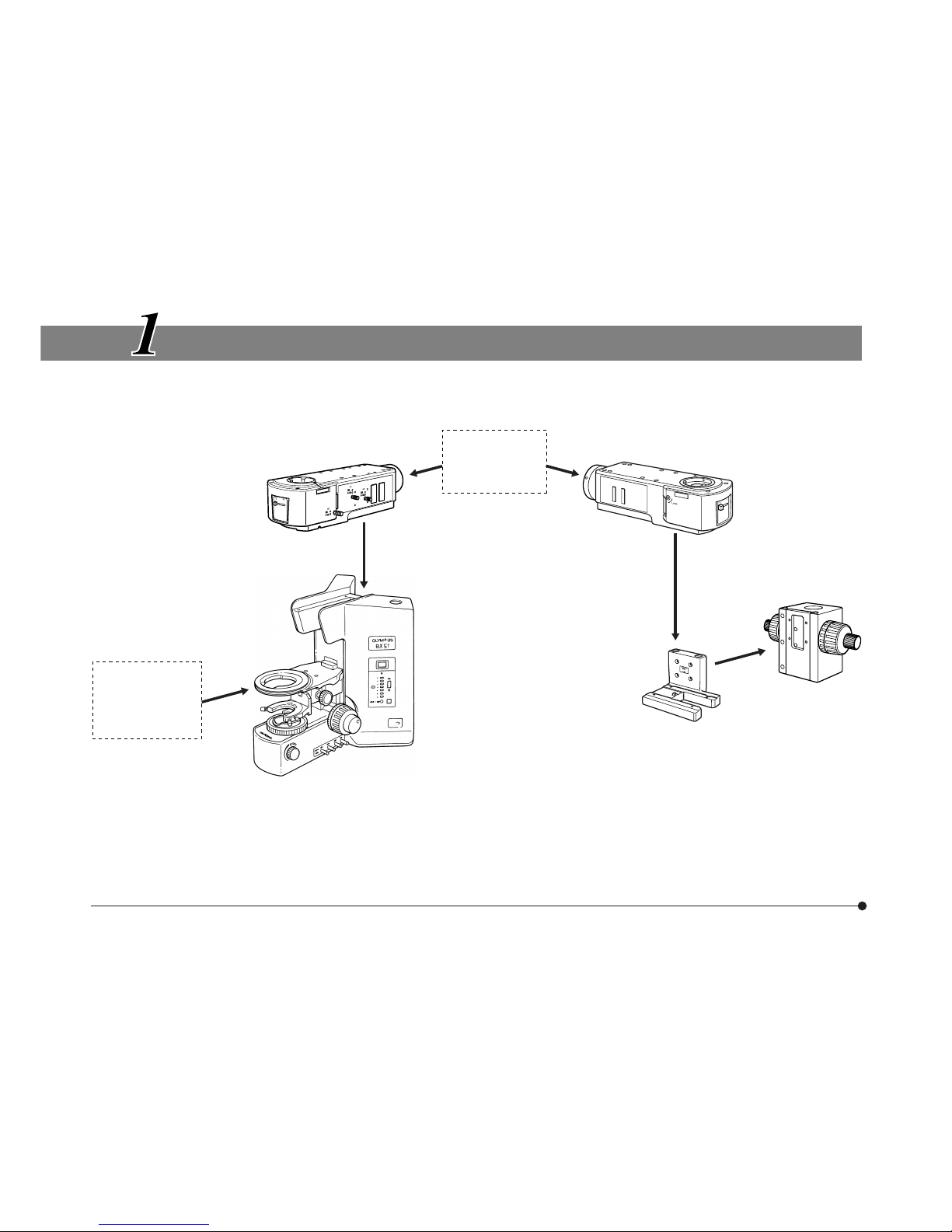
3
SYSTEM DIAGRAM
Reflected Light Brightfield/Darkfield
Illuminator
BX-RLA2
* Replace the standard stage with the stage for metallurgic specimens or the specimen
holder with the stage plate for edsier operation.
Reflected Light
Lamp Housing
Module
Reflected Light Brightfield/Darkfield
Illuminator
BX-RLA2
Stage for
Metallurgic
Specimens
or Stage
Plate*
Microscope frame
BX51RF
BX51TRF
Illuminator Holder
BXFM-ILH
Focusing Unit
BXFM-F
BX-RLA2
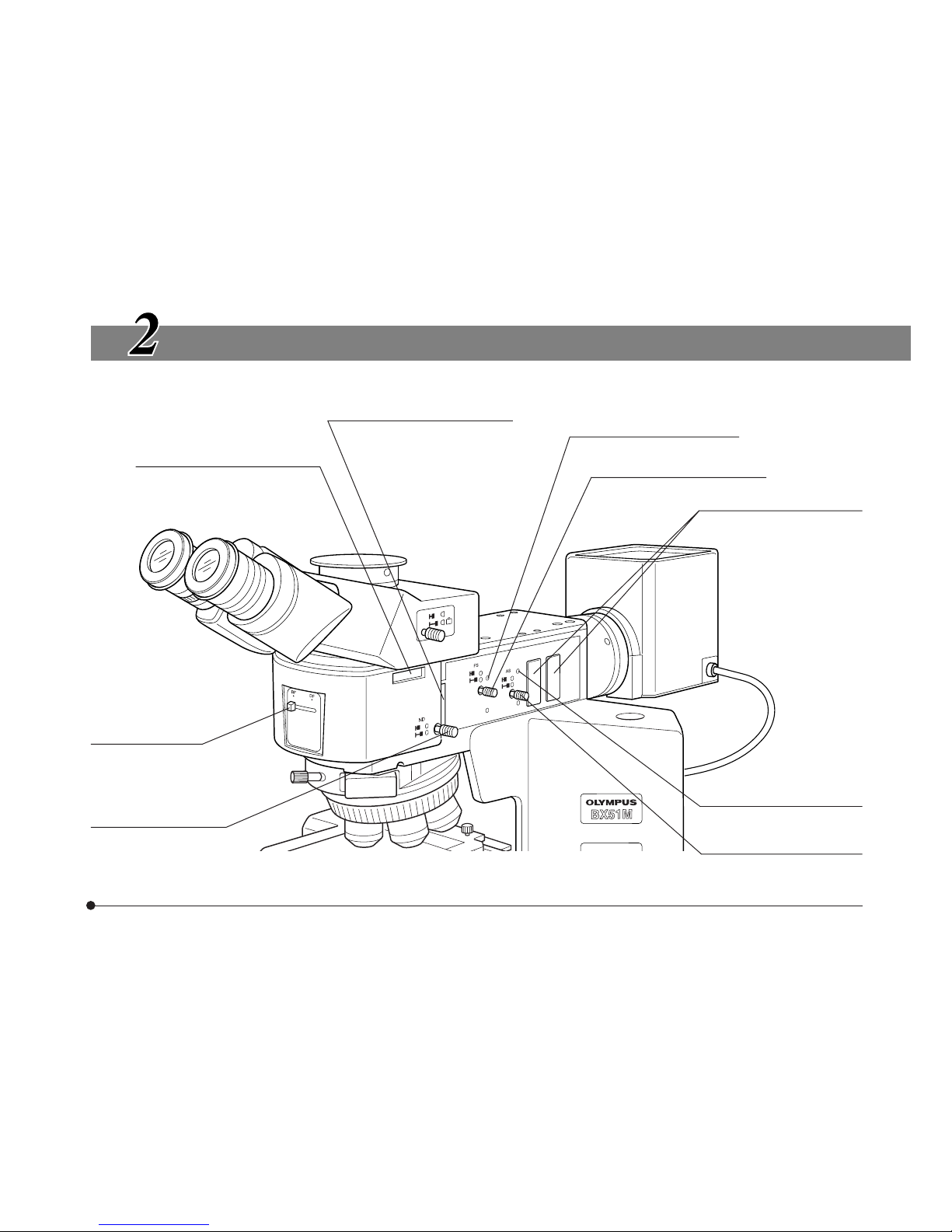
4
NOMENCLATURE OF BX-RLA2
Polarizer insertion slot (Page 14)
Analyzer insertion slot (Page 14)
Mirror selector lever
(Page 7)
ND filter knob (Page 10)
FS centering screws (Page 7)
Field iris diaphragm (FS) knob
(Page 7)
Filter insertion slot (Page 11)
#Always insert filters from
the left side!
AS centering screw (Page 9)
Aperture iris diaphragm (AS)
knob (Page 9)
5
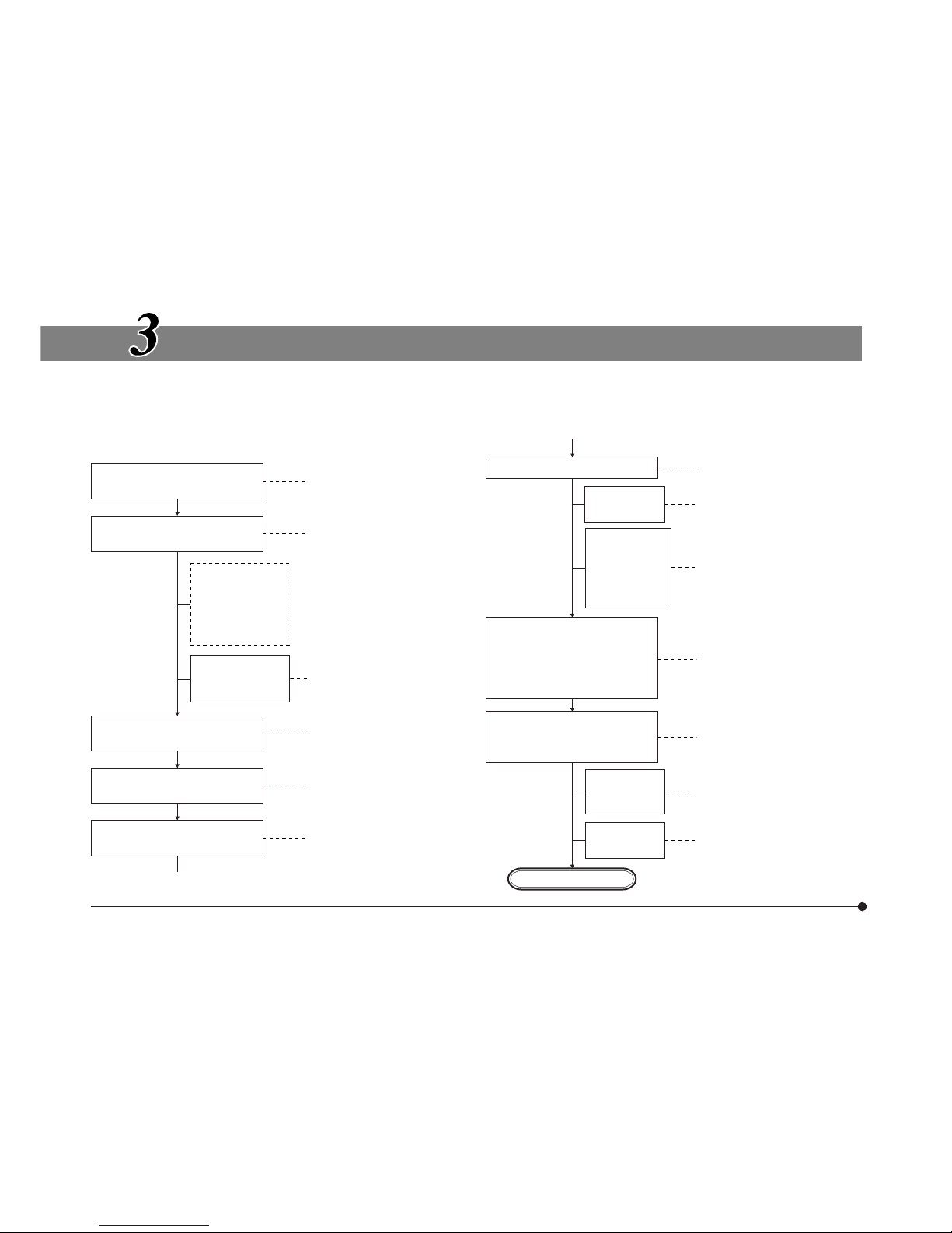
REFLECTED LIGHT BRIGHTFIELD/DARKFIELD OBSERVATION PROCEDURE
}The following flow shows the basic operating procedure for reflected light brightfield or darkfield observation. The operating
procedures for polarized light and Nomarski DIC observations will be described separately in their descriptions. (The microscope frame used is the BX51TRF.)
(Controls Used) (Page)
Select the brightfield (BF) or
darkfield (DF) observation.
@ Mirror selector lever (P. 7)
Set the main switch to “ I ”
(ON).
² Main switch
Disengage the
analyzer,
polarizer, filter,
etc. from the
light path.
Check
interlocking of
the ND filter.
³ ND filter knob (P. 10)
Select the light path
(trinocular tube only).
| Light path selector knob
Place the specimen on the
stage.
ƒ Stage plate
… X/Y-axis knobs
Engage the 10X objective in
the light path.
† Revolving nosepiece
Bring the specimen in focus.
‡ Coarse/fine adjustment
knobs
Adjust the
brightness.
Š Brightness control knob
Adjust the
interpupillary
distance.
Adjust the
diopter.
(Controls Used) (Page)
‰ Binocular tube
‹ Diopter adjustment ring
Adjust the aperture iris diaphragm and field iris diaphragm.
} Open both iris diaphragms
in case of DF observation.
ΠAS knob (P. 9)
™ FS knob (P. 7/8)
Engage the desired objective
in the light path and bring the
specimen in focus.
† Revolving nosepiece
‡ Coarse/fine adjustment
knobs
Insert the
required
filters.
š Filter insertion slot (P. 11)
Adjust the
brightness.
Š Brightness control knob
Start observation.
BX-RLA2
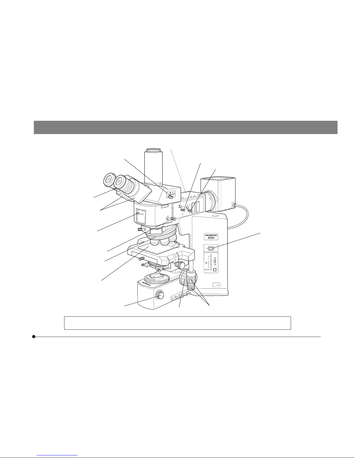
6
}Make a photocopy of the observation procedure page and post it near your microscope.
|
³
@
ƒ
²
Š
‡
…
‰
†
š
™
‹
Œ
Insertion from the left
7
USING THE CONTROLS OF BX-RLA2
1
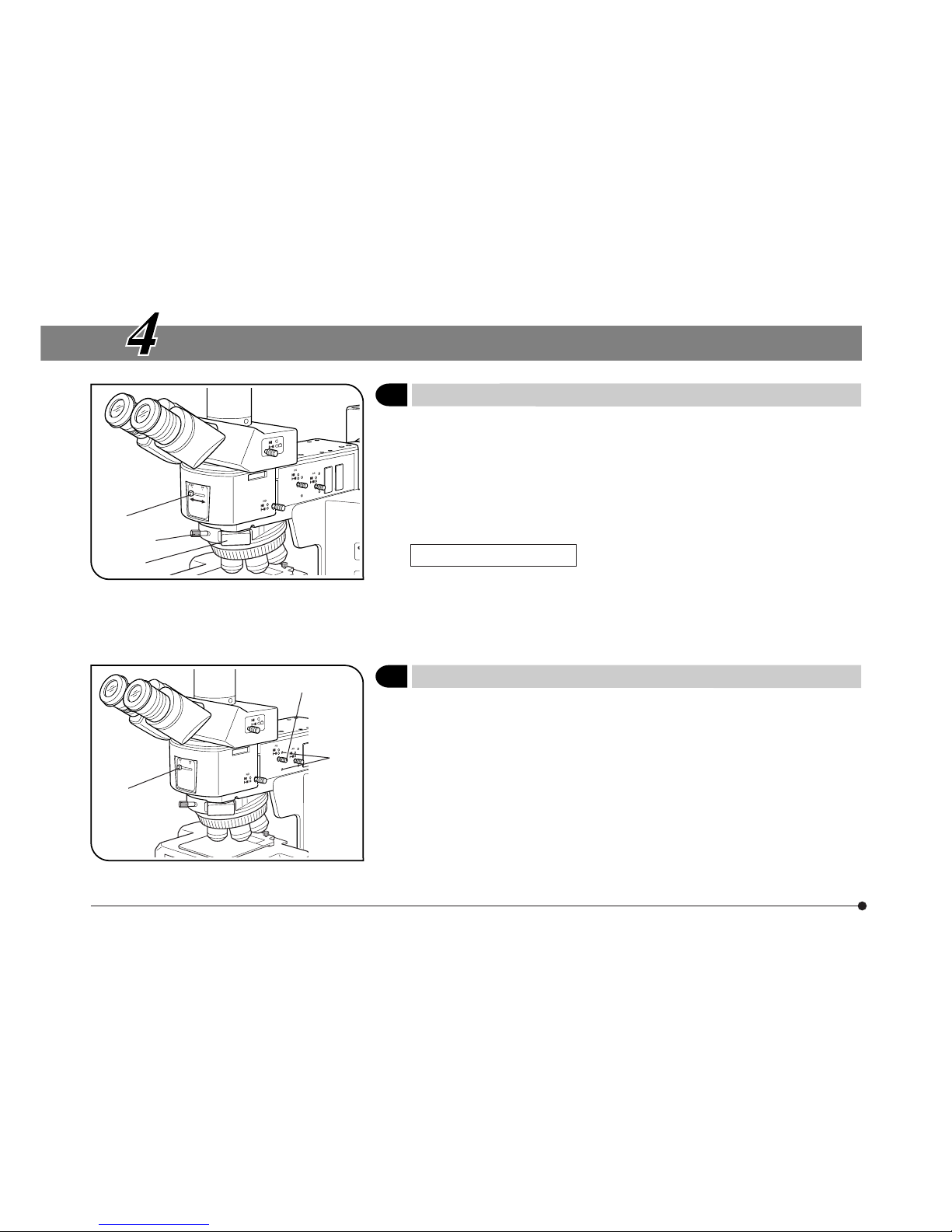
Selecting the Light Path
(Fig. 1)
Slide the mirror selector lever @ toward the indication of the mirror for the
desired observation method.
BF: Reflected light brightfield observation
DF: Reflected light darkfield observation
# Be sure to slide the mirror selector lever until it contacts the stopper
position.
Fig. 1
Effects of Dummy Slider
The dummy slider ² has been installed on the revolving nosepiece at the
factory. It can be replaced by loosening the clamping knob ³ when a DIC
prism is to be used. However, in observations other than DIC, be sure to
push in the dummy slider in order to prevent flare.
Fig. 2
2
Centering the Field Iris Diaphragm (FS)
(Fig. 2)
1. Slide the mirror selector lever @ to “BF”.
2. Engage the 10X objective by rotating the revolving nosepiece, place the
specimen on the stage and adjust approximate focusing.
3. Pull out the FS knob ² on the reflected light illuminator to reduce the
aperture iris stop a little.
4. Rotate the two FS centering screws ³ using the Allen screwdriver to adjust so that the field iris image becomes concentric with the field of view.
5. While pushing in the FS knob ², open the field iris diaphragm until the
field iris image inscribes the field of view. If the image is found to be
eccentric, adjust the centering again.
³
²
@
³
²
@
 Loading...