

Olympus IX2-DSU, BX-DSU Instruction Manual
DISK SCANNING BIOLOGICAL MICROSCOPE
Petition
Thank you for your adoption of OLYMPUS microscope, this time.
Please read this manual carefully in order to get optimum performance of this microscope
and for safety considerations.
When using microscope, please have this manual by you and keep it with care.
A
X6608


CONTENTS
Correct assembly and adjustments are critical for this system to manifest its full performance. If you are going to
assemble the microscope yourself, please read section 8, “ASSEMBLY” carefully.
INTRODUCTION - Be sure to read this section for safe
use of the equipment. -......................................................1
Caution ............................................................................................................... 1
Suggestions to unpacking ....................................................................... 1
Safety Caution ..................................................................................... 2
Symbol for safety considerations..............................................................................3
Warning labels .........................................................................................................4
When using the system ............................................................................ 5
Cleanup and storage................................................................................. 5
Caution....................................................................................................... 5
Manual conventions.................................................................................. 6
I. System Outline
1 SYSTEM OUTLINE....................................................... 1-1
1-1 Principle............................................................................................1-1
1-2 Features ............................................................................................ 1-2
1-3 System Configuration...................................................................... 1-3
1-3-1 In case of BX series.....................................................................................1-3
1-3-2 BX-DSU.......................................................................................................1-4
1-3-3 In case of IX series ......................................................................................1-5
1-3-4 IX2-DSU.......................................................................................................1-6

CONTENTS
II. DSU
2 SUMMARY OF OBSERVATION PROCEDURES ........ 2-1
3 DETAILS OF EACH OPERATION................................ 3-1
3-1 General Precaution for observation............................................... 3-1
3-2 Selection of fluorescent mirror unit............................................... 3-2
3-3 Table of Combination – Objective lens to each observation and
applicable disk ................................................................................. 3-5
3-4 Assignment of operating buttons on body (BX61, BX62 or BX61WI
only)................................................................................................... 3-7
3-5 Powering up ..................................................................................... 3-8
3-6 Focusing........................................................................................... 3-8
3-7 Changeover of visual mirror unit (front side)................................ 3-9
3-7-1 In case of BX ...............................................................................................3-9
3-7-2 In case of IX.................................................................................................3-9
3-8 Disk IN/OUT .................................................................................... 3-10
3-9 Shutter OPEN/CLOSE.................................................................... 3-10
3-9-1 In case of BX .............................................................................................3-10
3-9-2 In case of IX...............................................................................................3-10
3-10 Changeover of camera mirror unit (rear side)........................... 3-11
3-11 Filter change................................................................................. 3-11
3-12 Adjustment of field iris diaphragm.............................................3-12
3-13 Lamp centering ............................................................................ 3-13
3-14 Camera focus alignment ............................................................. 3-15
3-15 Power shutdown .......................................................................... 3-15
4 VARIETIES OF OBSERVATION METHODS ............... 4-1
4-1 Visual observation (BX)................................................................... 4-1
4-1-1 Simultaneous observation of reflected-light fluorescent and phase contrast 4-1

CONTENTS
4-1-2 Simultaneous observation of reflected-light fluorescent and transmitting
Nomarski differential interference.................................................................4-2
4-2 Visual observation (IX) ....................................................................4-4
4-2-1 Simultaneous observation of reflected-light fluorescence and phase contrast4-4
4-2-2 Simultaneous observation of reflected-light fluorescence and differential
interference (transmitting) ............................................................................4-5
4-3 Camera observation (BX-IX) ...........................................................4-6
4-3-1 Transmitting bright-field and transmitted light phase contrast observation ...4-6
4-3-2 Transmitting differential interference observation.........................................4-6
5 TROUBLESHOOTING GUIDE ..................................... 5-1
6 SPECTRAL CHARACTERISTICS OF FILTERS ......... 6-1
7 SPECIFICATIONS ........................................................ 7-1
7-1 BX Series ..........................................................................................7-1
7-2 IX Series............................................................................................ 7-2
8 ASSEMBLY................................................................... 8-1
8-1 System block diagram..................................................................... 8-1
8-1-1 In case of BX ...............................................................................................8-1
8-1-2 In case of IX.................................................................................................8-2
8-2 Installation of light illuminator........................................................ 8-3
8-2-1 In case of BX ...............................................................................................8-3
8-2-2 In case of IX.................................................................................................8-4
8-3 Installation of disk box .................................................................... 8-4
8-4 Removal of transportation lock ......................................................8-5
8-5 Installation of illuminator ................................................................8-6
8-6 Installation of lamp house............................................................... 8-6
8-7 Installation of mercury lamp ...........................................................8-7
8-8 Lamp power supply setting ............................................................8-9

CONTENTS
8-9 Installation of front side turret...................................................... 8-10
8-9-1 In case of BX .............................................................................................8-10
8-9-2 In case of IX...............................................................................................8-10
8-10 Installation of visual mirror unit (front side) ............................. 8-11
8-10-1 In case of BX ...........................................................................................8-11
8-10-2 In case of IX.............................................................................................8-12
8-10-3 Method to make optionnal fluorescent mirror unit.....................................8-13
8-11 IN/OUT of rear side turret ............................................................ 8-14
8-12 Installation of camera mirror unit (rear side) ............................ 8-14
8-13 Disk installation and change ...................................................... 8-15
8-14 Installation of light shielding tube (BX61, BX62, BX51 or BX52)8-16
8-15 Installation of UV-cut plate.......................................................... 8-17
8-15-1 In case of BX ...........................................................................................8-17
8-15-2 In case of IX.............................................................................................8-17
8-16 Installation of filter or shutter (In case of U-FWR or IX2-SHA) 8-17
8-17 Filter IN/OUT inside motorized filter wheel ............................... 8-18
8-18 Field iris diaphragm IN/OUT ....................................................... 8-19
8-19 Installation of camera adapter and filter.................................... 8-20
8-19-1 In case of DSU C-mount adapter.............................................................8-20
8-19-2 C-mount adapter for DSULAMBDA10 / C-mount adapter for Ludl............8-20
8-20 Installation of camera.................................................................. 8-22
8-21 DIP switch settings on control box (BX61, BX62 and BX61W1
only)................................................................................................. 8-23
8-22 Installation of motor drive board................................................ 8-23
8-23 Z board setting and installation.................................................. 8-24
8-23-1 In case of BX61 and BX62 .......................................................................8-24
8-23-2 In case of BX61W1 ..................................................................................8-25
8-23-3 In case of IX81.........................................................................................8-26
INTRODUCTION
1
Page
INTRODUCTION
-
Be sure to read this section for safe use of the equipment.
-
Caution
This manual – part or whole, shall not be used or reproduced without permission.
Suggestions to unpacking
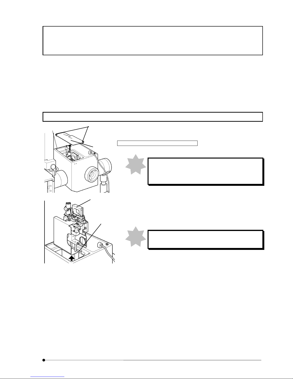
Release of transportation lock for disk unit
When powering up the control box without removing
transportation lock knob, the disk unit may be
damaged.
1. Loosen two fixing screws (2) of access panel (1) on top of disk box,
using dedicated the Allen screwdriver that comes with microscope
frame as accessory and detach the access panel (1).
2. Loosen fixing screw (3) from hole located at left side of disk box,
using the Allen screwdriver and pull up the disk unit (4).
Pull up the disk unit carefully so as not to hit it inside
wall of disk box.
Note
Note
(1)
(2)
(3)
(4)
(9)
INTRODUCTION
2
Page
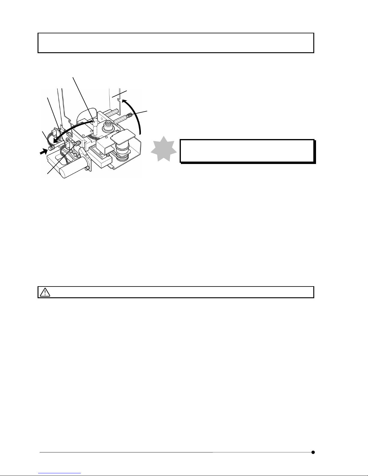
3. Loosen knob (5) of disk unit (at 2 places) and open disk protective
covers (6).
4. Loosen transportation lock knob (7) and remove it from the disk
unit (4).
Install the transportation lock knob you removed to the threaded
hole (8) of disk unit.
The transportation lock knob may be used for re-
transportation. Keep it with care.
When you continue to install disk, see Section 8-13 Disk
installation and change.
5. Return disk protective covers (6) to original position and tighten
knob (5) of disk unit (at 2 places) and fix the covers.
6. Align mount dovetail of disk unit (4) and mount dovetail (9) inside
the disk box and push the disk unit from top until it hits to dead
end.
7. Tighten fixing screw (3) with use of the Allen screwdriver and fix it.
8. Attach access panel (1) on top of disk box and tighten fixing
screws (2) (at 2 places) and fix it.
Safety Caution
l When you change disk, turn power of control box to OFF position and wait for one minute or more until the
turn of disk is completely stopped. The disk turns very rapidly so that they may be a danger to squeeze your
finger.
l When you change mirror unit for camera observation, change it after you turn the power of control box to
OFF position. During the change, it may be a danger to squeeze your finger if you accidentally touch the
changeover switch.
l Do not touch surface of disk with your hand. If the disk is blurred, observation image may be deteriorated.
l Do not touch lamp house mount adapter with your hand when the system is in use. As the adapter is
installed near the lamp house, the surface will get high temperature.
l Do not put power cord in the vicinity of lamp house. Lamp house will be of very high temperature. If power
cord touched the lamp house, the cord may be molten which would cause an electric shock.
Note
(5)
(7)
(6)
(7)
(5)
(8)

INTRODUCTION
3
Page
l Do not turn the lamp ON without installing lamp house to microscope. Ultraviolet ray of lamp is hazardous to
your eyes. Do not look at the light from lamp house directly.
l Do not look at excited light directly. When you use microscope, attach ultraviolet ray cutting plate and see
specimen and others through ultraviolet ray cutting plate for sure.
l When you change mirror unit at front side turret and rear side turret, observe the placement to the light path
in order of 1. fluorescent mirror unit and 2. reference mirror (No.1 position at each turret). If reference mirror
were set in front side turret and rear side turret, strong light would be applied to the specimen and it is
dangerous. (Regarding method of changeover for front and rear side turret, refer to Section 3-7
Changeover of mirror unit for visual observation (front side) and 3-10 Changeover of mirror unit for camera
observation (rear side).
Symbol for safety considerations
This system comes with the following symbols.
Understand the meaning of symbol and handle it safely.
Symbol Meaning
Do not touch with your hand as the surface is very hot.
It may cause a burn.
Be careful so as not to entangle your finger with disk or mirror unit for camera
observation.
Please read instruction manual definitely before you use the system.
In case of erroneous handling, it may cause injury of user or damage to
product.
Main switch is ON.
Main switch is OFF.
INTRODUCTION
4
Page
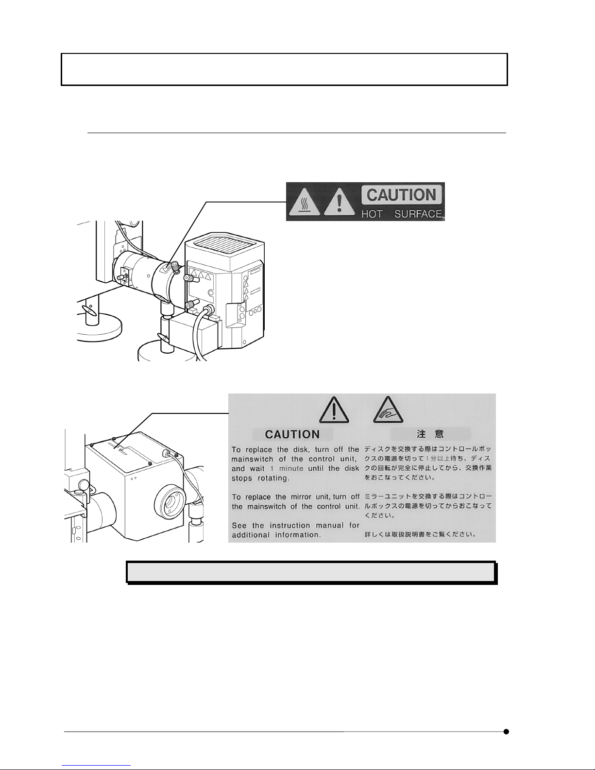
Warning labels
Warning label is attached to the place where caution is particularly required for operation. Observe the
instructions.
Lamp house mount adapter (Hot Surface caution)
Disk box (Entanglement caution)
When warning label is blurred or peeled off, contact our local sales office for change.
INTRODUCTION
5
Page
When using the system
l Handle this system with care so as not to give a shock as it is a precision instrument.
l This system requires independent fluorescent mirror unit for visual and camera observation respectively.
Install fluorescent mirror unit for visual observation to front side turret and install fluorescent mirror unit for
camera observation to rear side turret.
l Use high performance fluorescent mirror unit (HQ type) for camera observation in order to get optimum
optical performance.
l The fluorescent mirror unit – DSU-MRFPHQ – that comes with this system as accessory is for camera
observation.
Do not install it to front side turret for visual observation.
l Environment should be of room temperature at 10~35°C with relative humidity at 30~80%.
l Do not disassemble each section in vain as it may cause failure.
l Lamp house will get very hot. When installing, acquire adequate space in vicinity of lamp house (10cm or
more), particularly on top.
Cleanup and storage
l Never put dirt or fingerprint on surface of lens and filter, etc. In case of contamination, use gauze and wipe
out lightly. In case that the dirt or fingerprint does not come off with gauze, then, use mixed liquid (alcohol 3:
ether 7) to put in gauze and wipe out gently.
Liquid like ether or alcohol is very inflammable. Care must be taken when you handle
such liquid against fire and power switch ON-OFF procedure. Particularly, when using
ether or alcohol, pay utmost attention to ventilation of the room.
l When you clean other parts of the system, use a soft cloth dipped with diluted mild detergent to wipe each
section. Do not use organic solvent as it would deteriorate plastic parts or paint.
Caution
l If this system is used in other methods than those described in this manual, the safety is not guaranteed
and it may cause a failure or damage to the system. Use this system in accordance with instruction manual.
INTRODUCTION
6
Page
Manual conventions
This manual describes with use of the following manual conventions.
² Conventions of note, reference and point
Conventions Description
Indicates note to prevent injury of user and damage of product
(including home furniture, etc.).
Note
Typical note is indicated with
Note
.
Tip
Advice or hint for reference is indicated with
Tip
.
II..

SYSTEM OUTLINE / Principle
I.
System Outline
I.
1-1
Page
1 SYSTEM OUTLINE
Attaching this system to a microscope, it comprises a confocal microscope system without laser, but with use of
a white light source. It acquires a high contrast image through resolution enhanced in light axis direction very
rapidly.
In addition, Olympus motorized microscopes IX81, BX61WI, BX61 or BX62 and their related motorized units
may be controlled through a 3rd party software, which is designed for observation by CCD camera.
And the combination of such the software and the microscope may enable 3 dimensional observation, time-
lapse observation and so on.
The software controls changeover of confocal/non-confocal mode, ND filter synchronized to confocal or non-
confocal mode and filter cube inside the disk box in conjunction with motorized focusing control of motorized
microscope and thus, by changing wavelength through Z-drive of focusing control, it acquires images for myriad
observation.
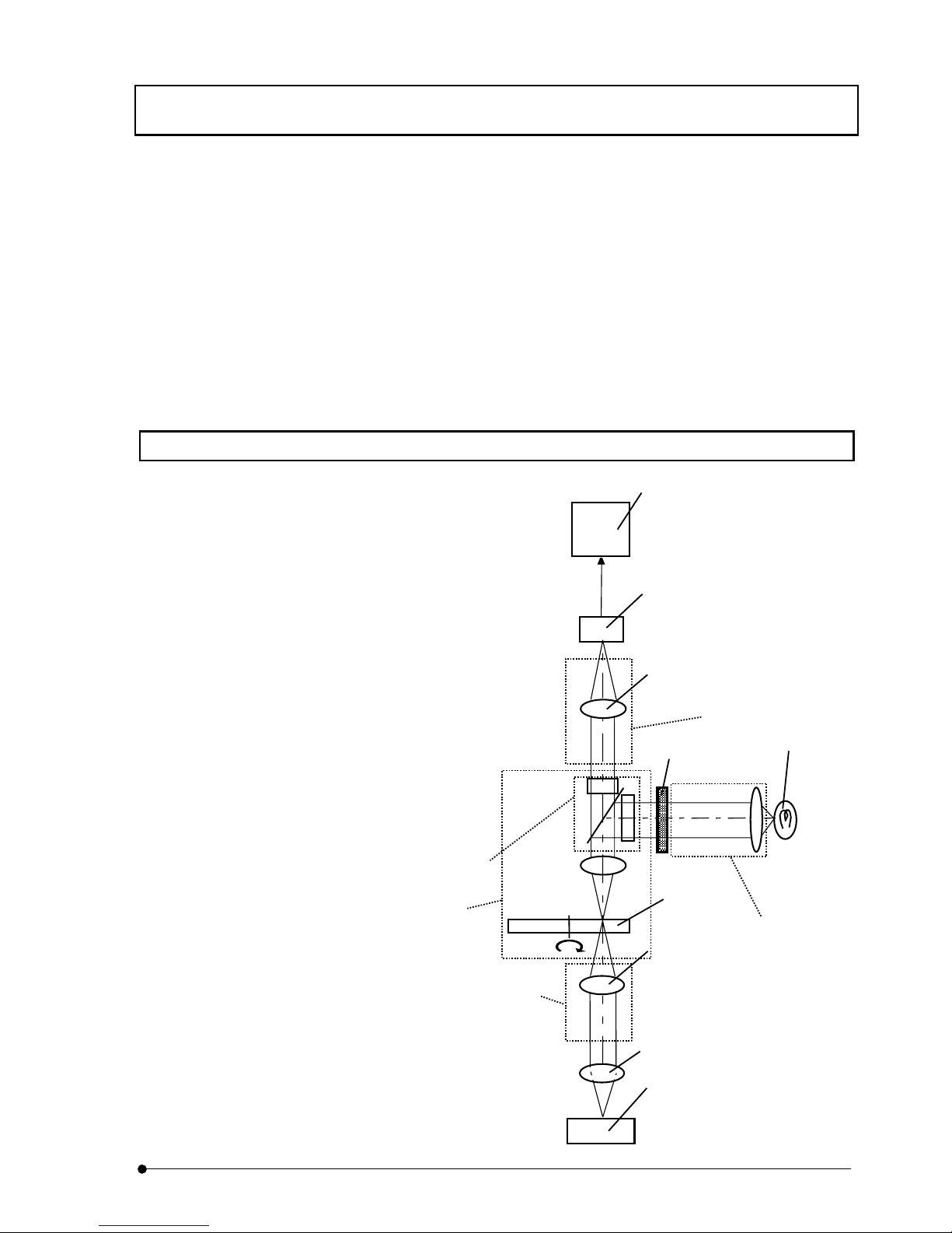
1-1 Principle
Light emitted from light source of mercury or xenon
reflects at fluorescent mirror and enters rotary disk
in light path. The rotary disk has a pattern of linear
lines that provides the effect equivalent to pin hole
by high speed rotation. Light that passes through
the pattern further passes through objective lens
and goes to the specimen. Fluorescence emitted
from the specimen passes through the objective
lens again and forms an image on the rotary disk.
Among image formed, a portion of light that is in
focus will pass through the disk and, CCD camera
captures the image and the specimen image will be
displayed on the monitor.
Light
source
ND Filter
Objective lens
Imaging lens
Imaging lens
Rotary disk
CCD Camera
Monitor
Specimen
Light
illuminator
Fluorescent
Mirror unit
Disk box
Camera adapter
Illumination
tube

SYSTEM OUTLINE / Features
I.
System Outline
I.
1-2
Page
1-2 Features
● Confocal disk employed enables to acquire image of confocal effect.
● As while light source such as mercury or xenon is used as a light source instead of
laser, excited light of various wavelengths can be used by combination of excitation
filter and cube.
● In case of non-confocal observation by displacing the disk from light path, an image
of deep focal point without confocal effect can be acquired. In case of confocal
observation by placing the disk in light path, a sharp image of shallow focal point
can be acquired. Changeover of confocal to non-confocal can be done very easily.
SYSTEM OUTLINE / System Configuration
I.
System Outline
I.
1-3
Page
1-3 System Configuration
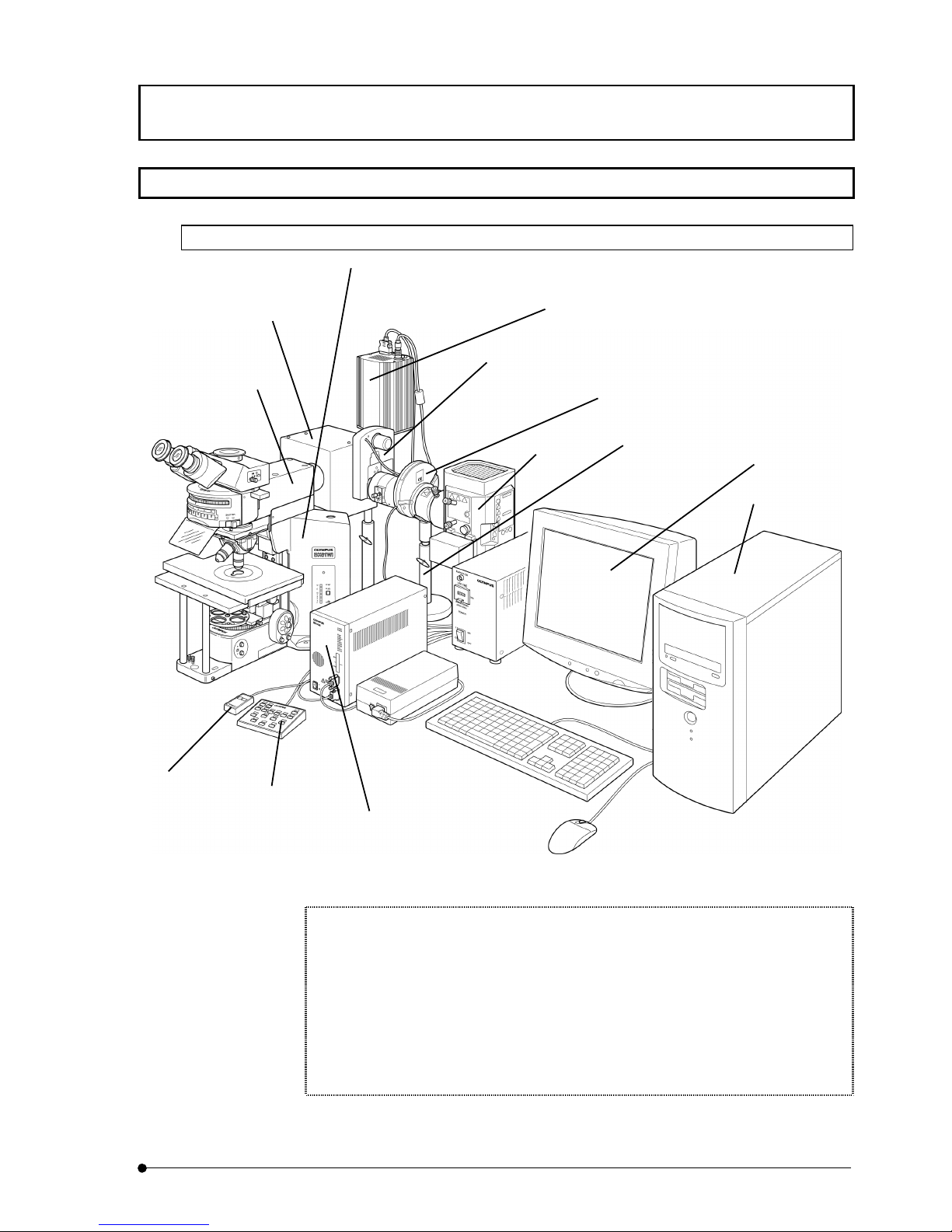
1-3-1 In case of BX series
Figure of BX series System Configuration
When you use this system in conjunction with microscope, you cannot integrate the
following units:
Motorized condenser (U-UCD8A) and motorized reflected light fluorescence (BX-RFAA
and BX-RLAA).
Motorized filter wheel (U-FWT and U-FWO)
When you integrate motorized revolving nosepiece, connect control box (IX2-UCB) with
use of connecting cable (U-REMMT).
Monitor
Computer
Cooled CCD Camera
Control box
(IX2-UCB)
DSU motor drive board
(DU-MTDRV) attached
Hand switch
(U-HSTR2)
Lamp
House
Microscope
(BX51, BX52, BX61, BX62,
BX51WI or BX61WI)
Light illuminator
for DSU BX
(DU-RFABX)
DSU Disk box
(DU-DBIX)
Motorized filter wheel
(U-FWR)
Stand for DSU BX
(DU-STBX)
DSU Hand switch
(DU-HSW)
Shutter and
Filter wheel
SYSTEM OUTLINE / System Configuration
I.
System Outline
I.
1-4
Page
Table of Instruction Manuals for Modules to be integrated
Instruction Manual Module name
SYSTEM MICROSCOPE BX51/BX52
MOTORIZED SYSTEM
MICROSCOPE
BX61/BX62
FIXED-STAGE UPRIGHT
MICROSCOPE
BX51WI
FIXED-STAGE MOTORIZED
UPRIGHT MICROSCOPE
BX61WI
CONTROL BOX FOR IX2 HAND
SWITCH
IX2-UCB
U-HSTR2
Cooled CCD Camera Manual for Cooled CCD Camera you may use
Computer/Monitor Manual for computer you may use
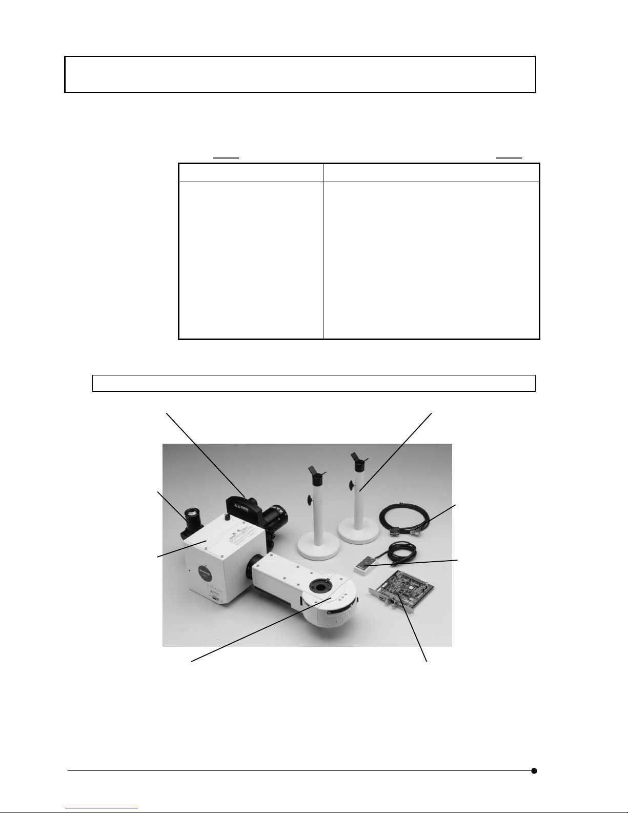
1-3-2 BX-DSU
BX-DSU includes the units, which have a mark "*" in its description on the above picture.
* DSU Hand switch
(DU-HSW)
* Disk control cable
* DSU motor drive board
(DU-MTDRV)
* DSU Disk box
(DU-DBIX)
DSU C-mount adapter
(DSU-CAD)
* Stand for DSU BX
(DU-STBX)
* Motorized filter wheel
(U-FWR)
* Light illuminator for DSU BX
(DU-RFABX)
SYSTEM OUTLINE / System Configuration
I.
System Outline
I.
1-5
Page
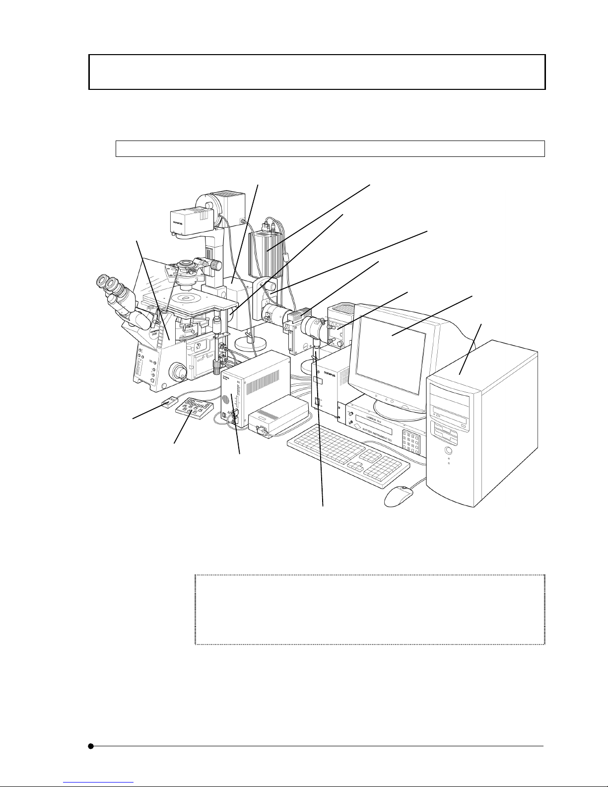
1-3-3 In case of IX series
Figure of IX Series System Configuration
When you use this system in conjunction with microscope (IX71 or IX81), you cannot
integrate with the following units:
Motorized fluorescent mirror unit cassette (IX2-RFACA) and motorized filter wheel (U-
FWT and U-FWO).
Monitor
Computer
Cooled CCD Camera
Control box
(IX2-UCB)
DSU motor drive board
(DU-MTDRV) attached
Hand switch
(U-HSTR2)
Shutter and
Filter wheel
Lamp
House
Microscope
(IX71, IX81)
Light illuminator
for DSU IX
(DU-RFAIX)
DSU Disk box
(DU-DBIX)
Motorized filter wheel
(U-FWR)
Stand for DSU IX
(DU-STIX)
DSU Hand switch
(DU-HSW)
SYSTEM OUTLINE / System Configuration
I.
System Outline
I.
1-6
Page
Table of Instruction Manuals for Modules to be integrated
Instruction Manual Module name
INVERTED RESEARCH
MICROSCOPE
IX71
MOTORIZED INVERTED
RESEARCH MICROSCOPE
IX81
CONTROL BOX FOR IX2 HAND
SWITCH
IX2-UCB
U-HSTR2
Cooled CCD Camera Manual for Cooled CCD Camera you may use
Computer/Monitor Manual for computer you may use
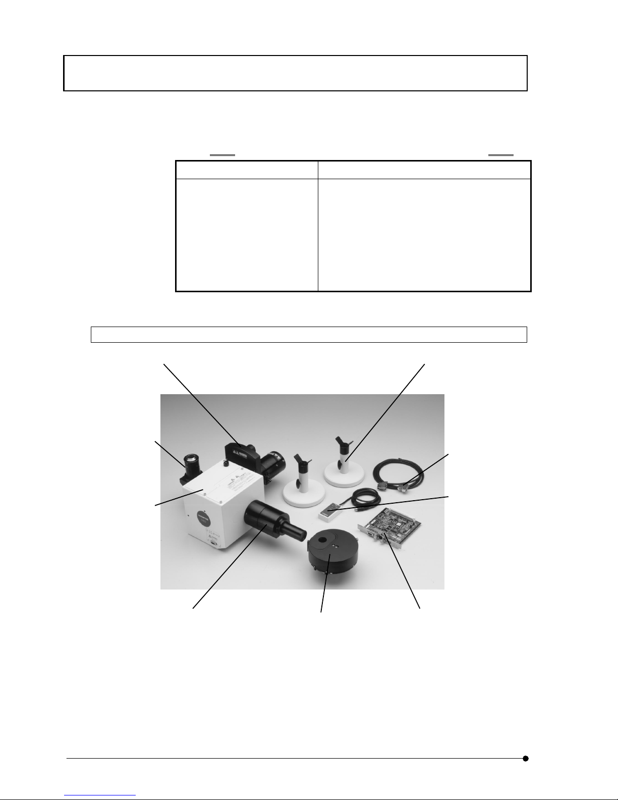
1-3-4 IX2-DSU
IX2-DSU includes the units, which have a mark "*" in its description on the above picture.
* DSU motor drive board
(DU-MTDRV)
* DSU Hand switch
(DU-HSW)
* Disk control cable
* DSU Disk box
(DU-DBIX)
DSU C-mount adapter
(DSU-CAD)
* Stand for DSU IX
(DU-STIX)
* Motorized filter wheel
(U-FWR)
* Light illuminator for DSU IX
(DU-RFAIX)
* Mirror unit cassette

IIII..

SUMMARY OF OBSERVATION PROCEDURES
II .
DSU
II .
2-1
Page
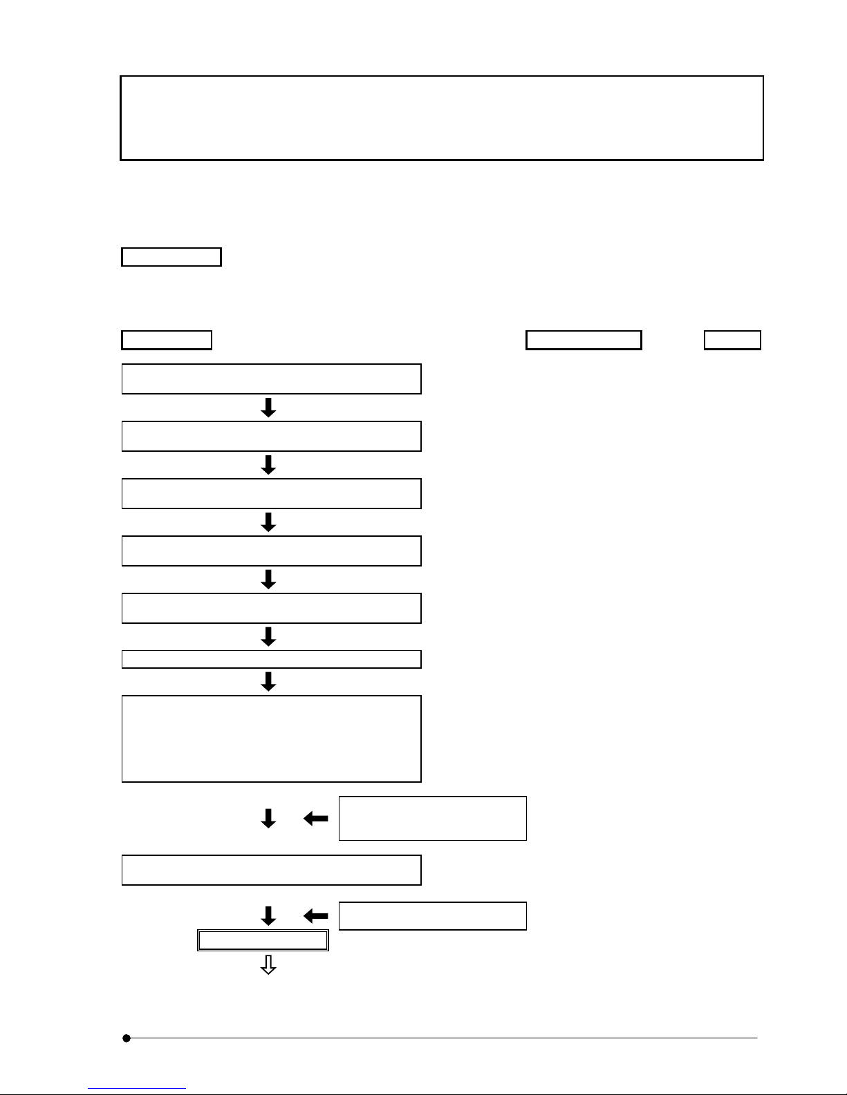
2 SUMMARY OF OBSERVATION
PROCEDURES
This section describes procedures for fluorescent observation by visual method followed by camera observation
by confocal mode.
Preparation
•Install fluorescent mirror unit and objective lens applicable to observation method.
•Do centering of mercury lamp or xenon lamp.
•Bring camera in focus.
Procedures
Where Ref.
Turn power switch of each system to ON position
and do initialization.
.......................... Power switch of each
system
3-5
Turn power switch of lamp to ON position and wait
until arc is stabilized. (5 to 10 minutes).
.......................... Main switch of lamp power 3-5
Set specimen on stage.
.......................... Lateral/Longitudinal feed
handle
-
Turn turret of front side and insert visual mirror unit
that fits to specimen into light path.
.......................... Visual mirror unit (front
side)
3-7
Turn turret of rear side and insert No.1 reference
mirror into light path
.......................... Camera mirror unit (rear
side) change button
3-10
Displace disk from light path.
.......................... Disk IN/OUT button 3-8
Put objective lens in light path and open shutter to
bring the specimen in focus.
.......................... Objective lens change
button, revolving
nosepiece, shutter
open/close knob or Electric
shutter or focusing handle
or coarse/fine handle
3-6
3-9
Adjust light intensity with use of
ND filter to put in or remove
from light path.
Filter change button 3-11
Adjust entire field of view to be uniformly bright.
.......................... Collector lens focusing
knob
3-12
Adjust field iris diaphragm.
Field iris diaphragm lever 3-12
Visual observation
(To next page)
Summary of observation procedures
II .
DSU
II .
2-2
Page
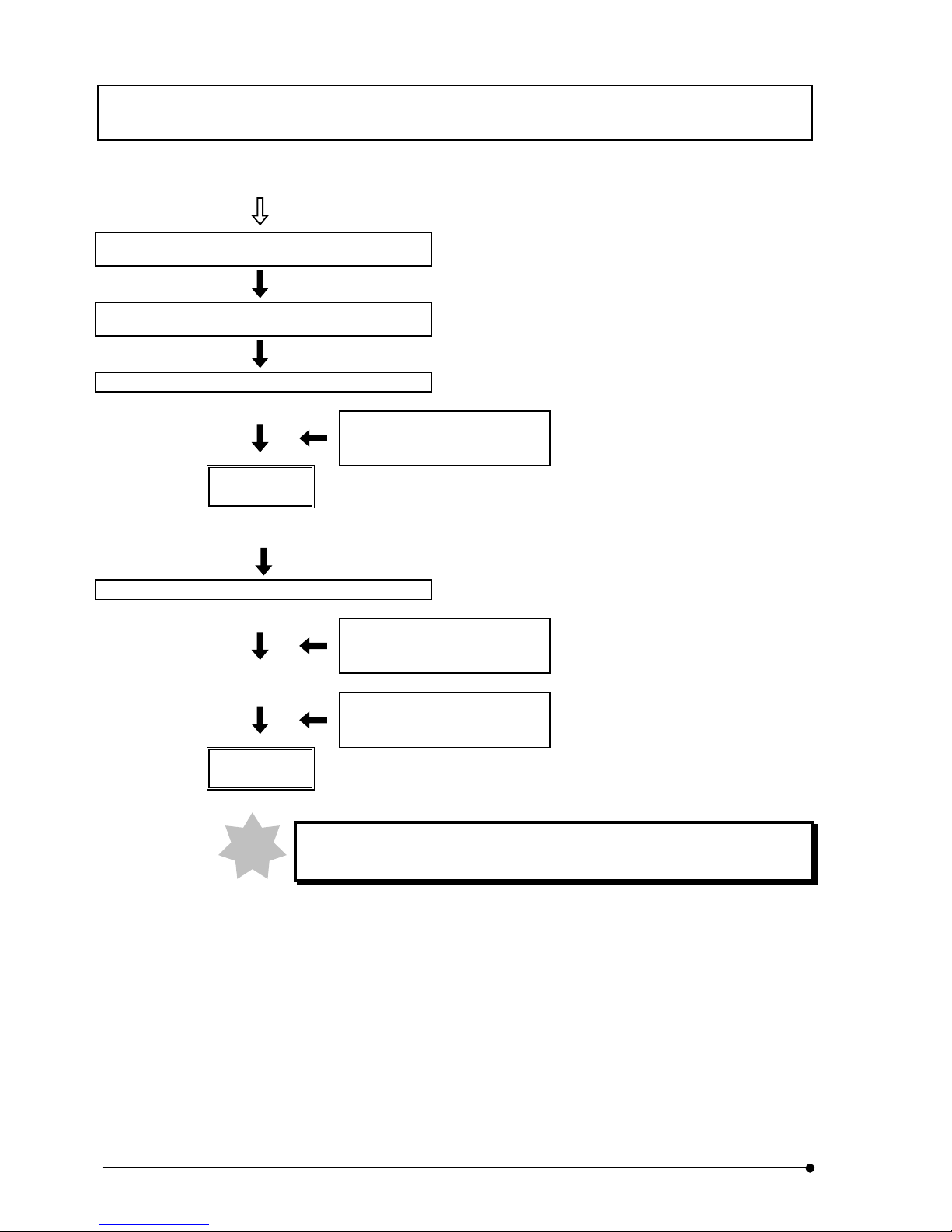
(From previous page)
Turn turret of rear side and put camera mirror unit
that suits to the specimen.
.......................... Camera mirror unit (rear
side) change button
3-10
Turn turret of front side and put No.1 reference
mirror into light path
.......................... Visual mirror unit (front
side)
3-7
Set camera setting for observation.
.......................... Control of camera -
Adjust light intensity with use of
ND filter to put in or remove
from light path.
Filter change button
Camera
observation
Put disk into light path.
.......................... Disk IN/OUT button 3-8
Adjust light intensity with use of
ND filter to put in or remove
from light path.
Filter change button
If necessary, set camera setting
to meet with observation.
Control of camera
Confocal
observation
During observation, use shutter for short interruption of observation.
Note

DETAILS OF EACH OPERATION / General Precaution for observation
II .
DSU
II .
3-1
Page
3 DETAILS OF EACH OPERATION
3-1 General Precaution for observation
1. Verify that input voltage/frequency to be used is within the range of that described
in identification plate of the system.
2. Verify that power cord as well as connecting cord is securely connected.
3. In case that transmitted light phase contrast observation or transmitted light DIC
(Differential Interference Contrast) observation only is required, make one place
where fluorescent mirror unit is not attached and do observation.
4. Use field iris diaphragm, squeezing it until it circumscribes to the filed of view and,
in case that it is out of center, adjust it with use of the Allen screwdriver.
5. Use immersion oil for objection lens of immersion type.
6. When you use objective lens of LCPlanFI series, attach a correction cap that
compensates thickness of container used for objective lens that is used for
observation. See instruction manual for IX2 series for kinds of correction caps
available.
7. Objective lens, UPlanApo40x (cover glass thickness offset 0.11~0.23), PlanApo40x
(0.11~0.23), UApo40x3/340 (0.11~0.23), UPlanApo60xW3 (0.15~0.20),
LCPlanFI40x (0~2.5) and 60x (0~2.5), all come with a correction ring; can
compensate deterioration of resolution due to variance of cover glass thickness.
Correction method
While turning correction ring, seek the position by adjusting
focus with use of fine-tuning handle and get best possible
resolution.
8. When a pause is required frequently during observation, use shutter (manual or
electric shutter).
(If mercury lamp is turned ON-OFF so frequently, it may deteriorate life of lamp).
9. Note to color deterioration on specimen
In case that observation is done with use of objective lens of high power, color
deterioration on specimen may occur earlier and contrast of fluorescent image may
be deteriorated. In such case, the color deterioration may defer if intensity of
excited light is lowered to a certain extent and a good fluorescent image may be
acquired. Use of ND filter is recommended to lower intensity of the excited light if it
does not bother the observation. Alternatively, use shutter so as not to apply light
source to specimen so often than it is necessary. Moreover, it can defer the color
deterioration if anti-color deterioration agent commercially available (DABCO) is
used. Particularly, it is recommended that anti-color deterioration agent is used with
high power observation.
DETAILS OF EACH OPERATION / Selection of fluorescent mirror unit
II .
DSU
II .
3-2
Page
Be careful that specimen of certain kind cannot use anti-color
deterioration agent.
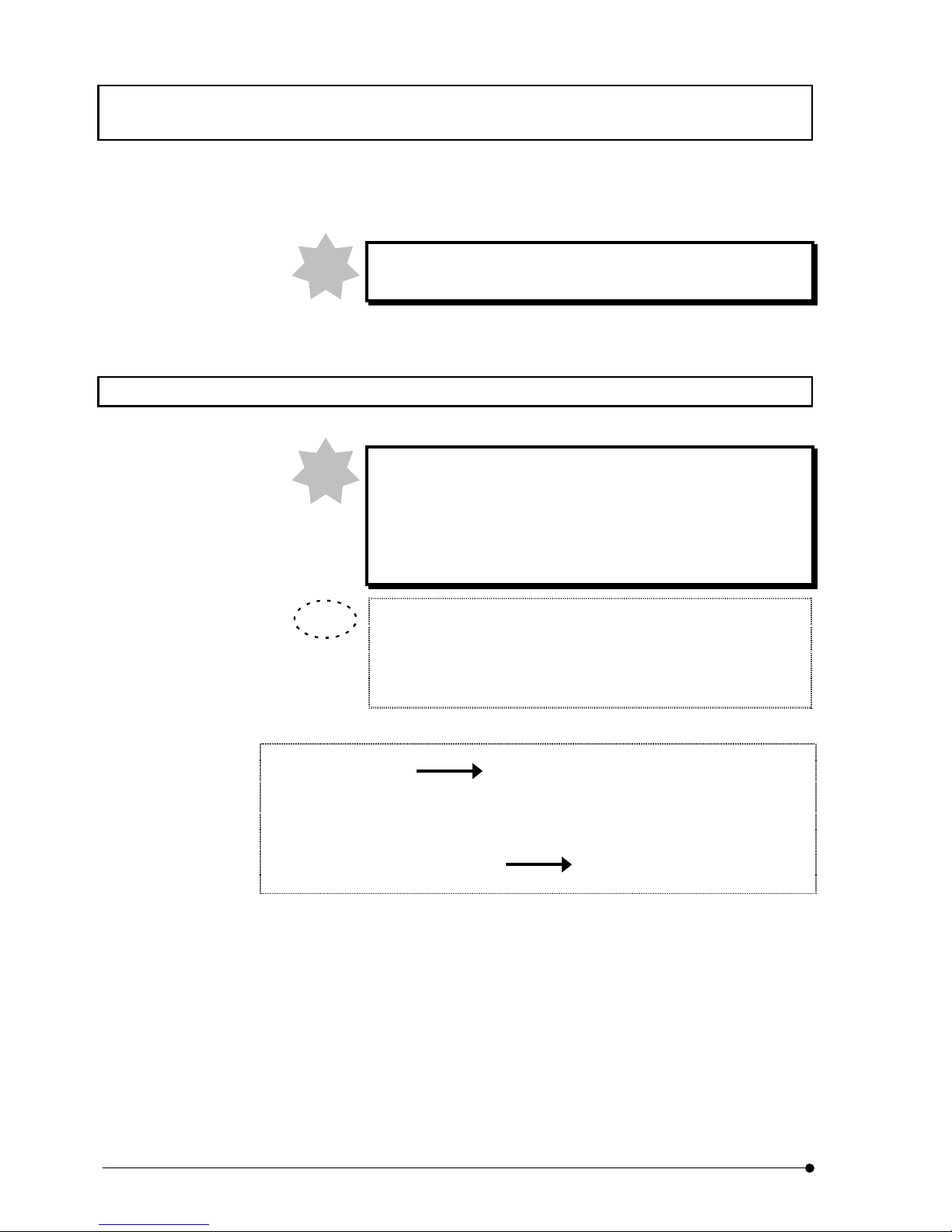
3-2 Selection of fluorescent mirror unit
Select fluorescent mirror unit that has excitation to meet with coloring matter.
Do not use fluorescent mirror unit in combination with brightfield
of view mirror unit (U-MBF3). U-MBF3 is very bright and it may
hurt your eyes. If for any reason the mix use of mirror units is
required, use U-MBFL3 that ND filter is built in or insert ND filter of
3%.
Note to excitation bandwidth
A few sets of excitation filters combined for different bandwidth are
available. Typically, a set of wide bandwith (W) is used but, in case of
the followings, the use of a separate set may be better.
(1) In case that brightness of fluorescence is dark
(B,G excitation only) Change to super wide bandwidth (SW)
(In case of SWB2, fluorescence that comes from
substance other than fluorescent coloring matter may
become stronger.)
(2) In case fluorescence that comes from substance other than
fluorescent coloring matter is strong Change to narrow bandwidth (N)
(Brightness of fluorescence becomes slightly darker.)
Note
TIP
Note
 Loading...