

Olympus BX51-P, BX52-P, BX41-P Instructions Manual

INSTRUCTIONS
BX51/52-P,BX41-P
POLARIZING MICROSCOPE
This instruction manual is for the Olympus Polarizing Microscope Model BX51/52-P, BX41-P. To obtain
optimum performance and to familiarize yourself fully with the use of your microscope, we recommend
that you read this manual together with the instruction manual for the BX51/BX52, BX41 microscope
thoroughly before use. Retain this instruction manual in an easily accessible place near the work desk
for future reference.
A X 7 3 4 4


IMPORTANT — Be sure to read this chapter for safe use of the equipment. — 1
BX51/52-P,BX41-P
CONTENTS
1 NOMENCLATURE
2
2 ASSEMBLY
3-9
2-1 Assembly Diagram ......................................................................................................................................................................................................................................... 3
2-2 Detailed Assembly Procedure ................................................................................................................................................................................................ 4-9
3 CONTROLS
10-11
4 USING THE CONTROLS
12-15
4-1 Stage ......................................................................................................................................................................................................................................................................... 12 -14
4-2 Intermediate Polarizing Attachment...................................................................................................................................................................................... 15
5 POLARIZED LIGHT OBSERVATION
16-26
5-1 Adjustments Before Observation .................................................................................................................................................................................... 16-24
5-2 Orthoscopic Observation ..................................................................................................................................................................................................................... 25
5-3 Conoscopic Observation ...................................................................................................................................................................................................................... 26
6 SPECIFICATIONS
27-28
7 OPTICAL CHARACTERISTICS
29
8 TROUBLESHOOTING GUIDE
30
1
IMPORTANT
1. A microscope is a precision instrument. Handle it with care and avoid subjecting it to sudden or severe impact.
2. The BX51/52, BX41 series microscope can be used with up to two additional intermediate attachments (e.g., U-DO3 dualviewing attachment, U-CA or U-ECA magnification changer, etc.). When using an additional intermediate attachment,
please make sure with your Olympus representative or the latest brochure.
3. Do not use the microscope where it is subjected to direct sunlight, high temperature and humidity, dust or vibrations.
Install it on stable, level bench. For operation environment conditions, see SPECIFICATIONS on page 28.
If the microscope is used in a manner not specified by this manual, the safety of the user may be imperiled. In addition, the
equipment may also be damaged. Always use the equipment as outlined in this instruction manual.
1
Getting Ready
2
Caution
The following symbols are used to set off text in this instruction manual.
: Indicates that failure to follow the instructions in the warning could result in bodily harm to the
user and/or damage to equipment (including objects in the vicinity of the equipment).
# : Indicates that failure to follow the instructions could result in damage to equipment.
} : Indicates commentary (for ease of operation and maintenance).
The BX51/52-P and BX41-P have different combinations of microscope frames and stages.
Module BX51/52-P BX41-P
Microscope frame BX51TF/BX52TF BX41TF
Stage U-SRP U-SRG2
2
BX51/52-P,BX41-P
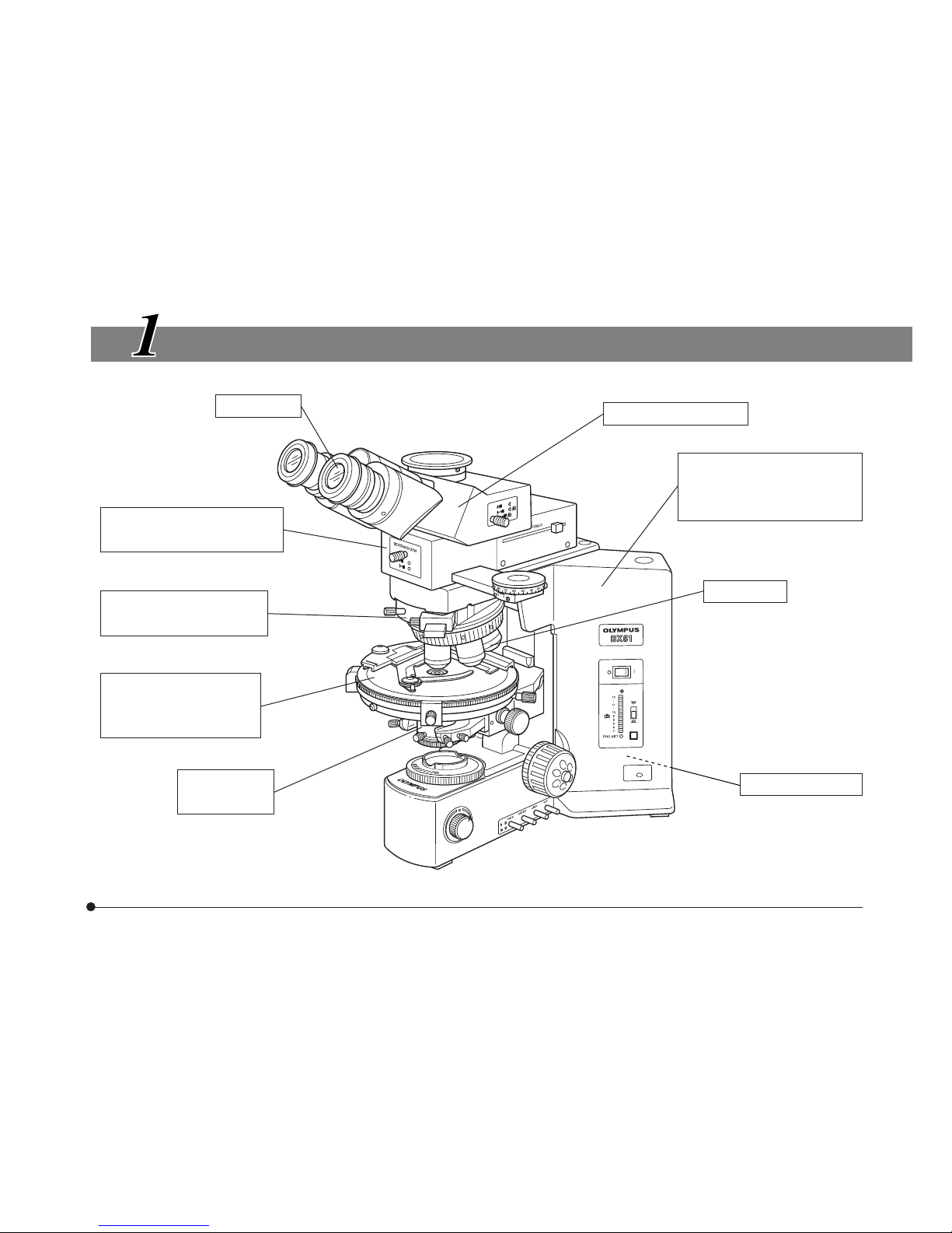
NOMENCLATURE
Eyepiece
* Polarizing intermediate
attachment
* Centerable revolving
eyepiece
* Polarizing rotatable
stage, or
Rotatable stage
Observation tube
BX51/52 Microscope
frame, or
BX41Microscope frame
*
Objective
(Strain-free objective series)
Lamp housing
*Components for polarized light observation
* Strain-free
condenser
3
ASSEMBLY
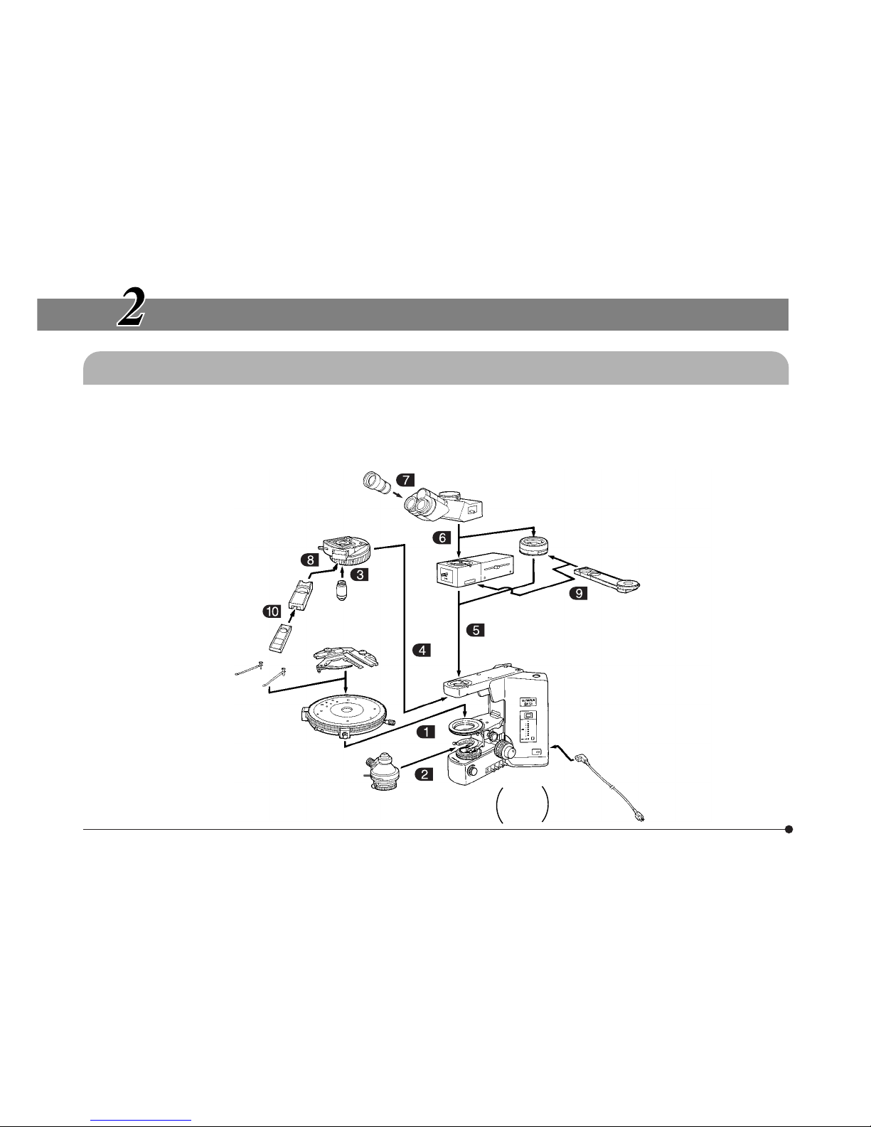
The diagram below shows how to assemble the various components. The numbers indicate the order of assembly.
}For details on the BX51/52, BX41 microscope frame, consult the BX51/52, BX41 manual.
#When assembling the components, make sure that all parts are free of dust and dirt, and avoid scratching any
parts or touching glass surfaces.
2-1 Assembly Diagram
Eyepiece
Centerable revolving
nosepiece (U-P4RE)
Test plate adapter
(U-TAD)
Sensitive tint plate
(U-TP530)
Quarter wave plate
(U-TP137)
Strain-free
objective
Mechanical stage
(U-FMP)
Stage clips
Polarizing
rotatable stage
(U-SRP)
Rotatable stage
(U-SRG2)
Polarizing
intermediate
attachment
(U-CPA)
Observation tube
Intermediate attachment
for AN360P (U-OPA)
Rotatable analyzer
(U-AN360P-2)
Power cord
Microscope frame
BX51TF
BX52TF
BX41TF
Strain-free condenser
(U-POC-2)
*6 types of compensators available
*
4
BX51/52-P,BX41-P
Fig. 2
…
2-2 Detailed Assembly Procedure
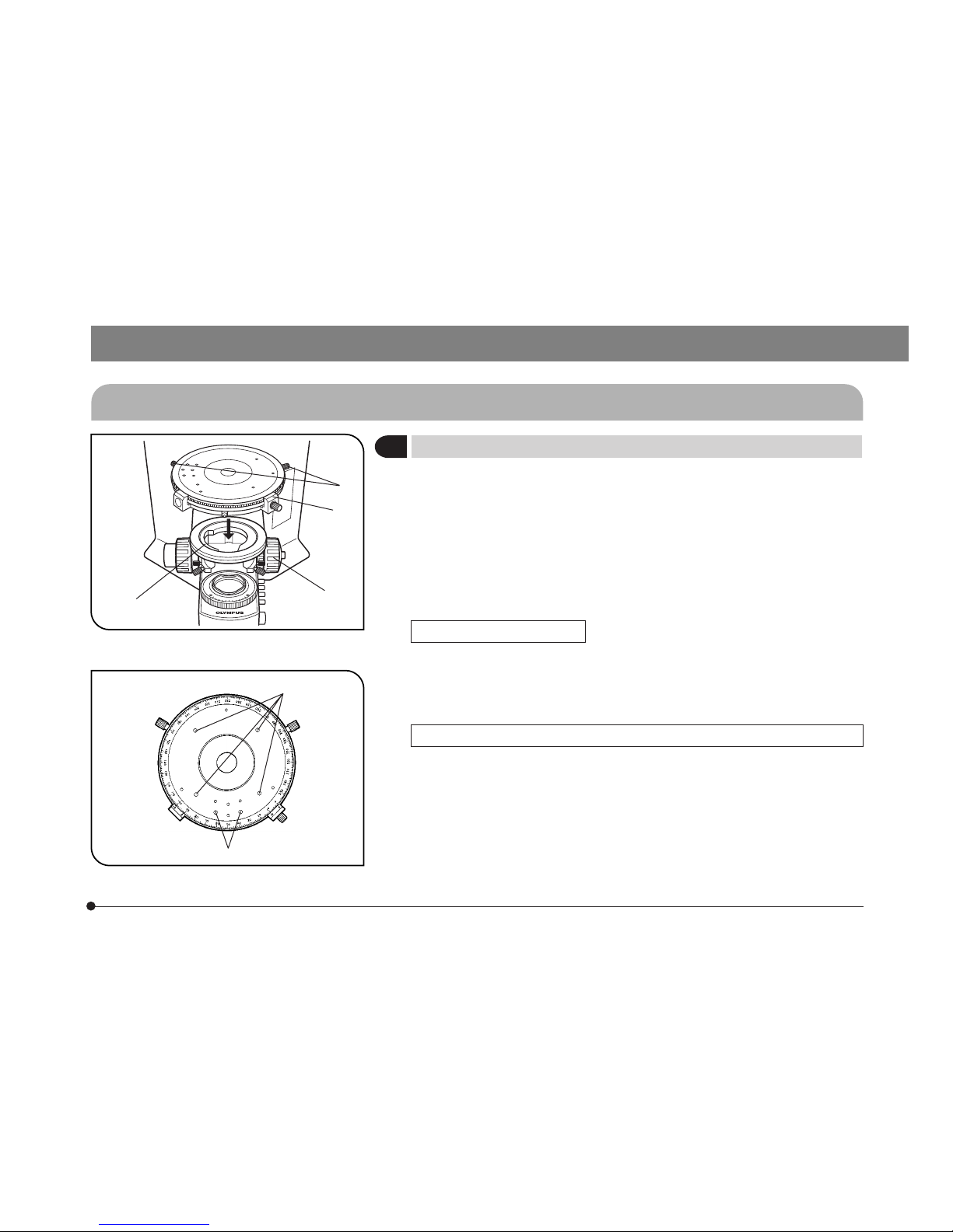
1
Attaching the Stage (U-SRP)
(Fig. 1)
1. Turn the coarse adjustment knob @ to lower the substage assembly ² to
its lower limit.
2. Loosen the centering knobs ³.
3. Position the stage with the vernier scale | in front, and carefully lower the
stage onto the round dovetail on the stage bracket ² with the positioning
pin on the stage aligned with the groove on the front of the stage bracket,
then loosely tighten the centering knobs.
When using the U-SRG2
· Using the Allen screwdriver provided with the microscope frame, loosen
the clamping screw on the front of the stage. Then, after lowering the
stage onto the stage bracket, tighten the clamping screw.
Mounting Stage Clips and Mechanical Stage (U-FMP) (Fig. 2)
· Insert the stage clips securely into any two holes ƒ on the stage top
surface.
· Mount the mechanical stage so that the positioning pins on the underside fit into the positioning holes … on the stage top surface. Using the
Allen screwdriver provided with the microscope frame, tighten the clamping
screw.
ƒ
Fig. 1
@
²
³
|
5
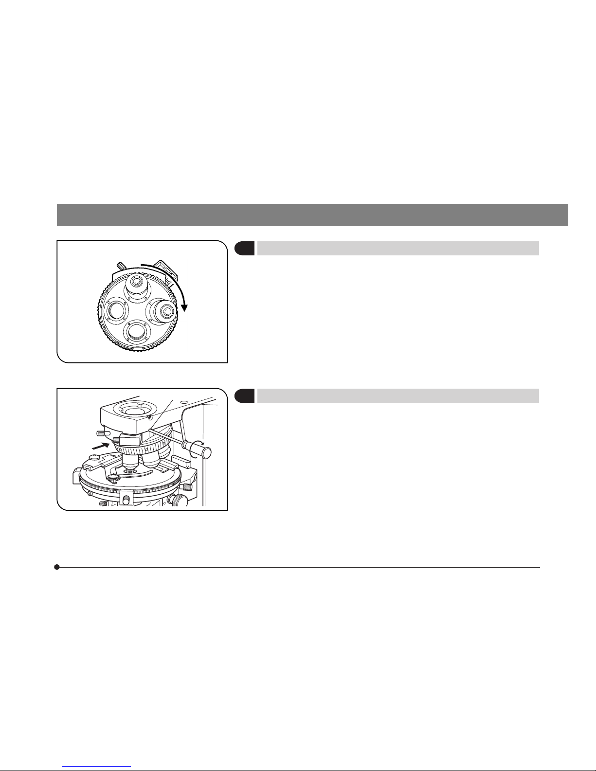
1. Turn the coarse adjustment knob @ to raise the stage to its upper limit.
2. Turn the condenser height adjustment knob ² to lower the condenser
holder to its lower limit.
3. Loosen the condenser clamping screw ³.
4. Position the condenser with the scale markings in front, insert it into the
substage fork as far as it will go.
Align the positioning pin at the back of the condenser with the groove in
the substage fork. Swing the top lens out of the way before inserting the
condenser.
5. Tighten the condenser clamping screw, then raise the condenser to its
upper limit.
2
Mounting the Condenser (U-POC-2)
(Fig. 3)
²
Fig. 3
³
@
6
BX51/52-P,BX41-P
# Insert the 10X or 20X objective into the primary hole (position where
black rubber plugs are inserted into the centering holes on the nosepiece).
Mount the other objectives in such a manner, that the magnification increases from low to high power in a clock-wise direction from the primary
hole.
4
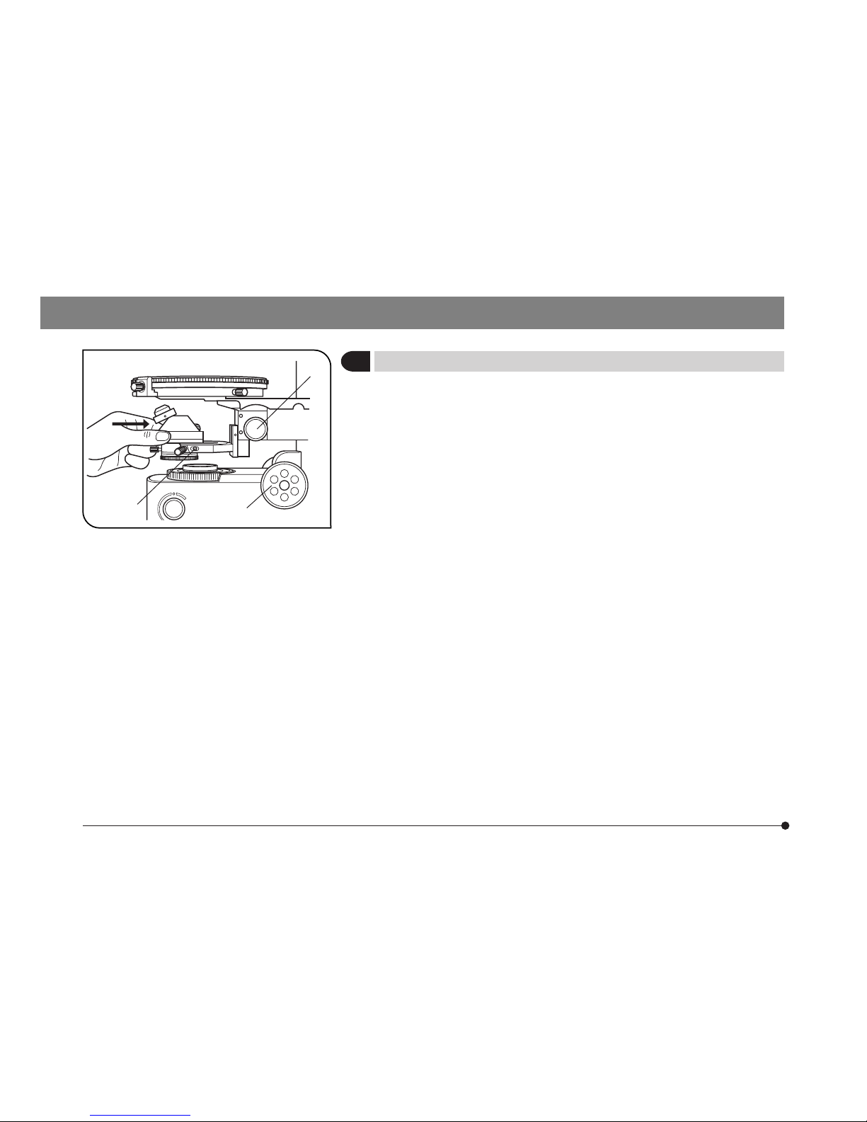
Mounting the Revolving Nosepiece (U-P4RE) (Fig. 5)
1. Turn the coarse adjustment knob to lower the stage all the way.
2. Using the Allen screwdriver, loosen the nosepiece clamping screw @ on
the microscope frame.
3. Carefully slide the nosepiece along the dovetail to its limit, in the direction
of the arrow.
4. Clamp the nosepiece by tightening the nosepiece clamping screw.
Fig. 4
Low
High
Fig. 5
3
Mounting the Objectives (Fig. 4)
@
7
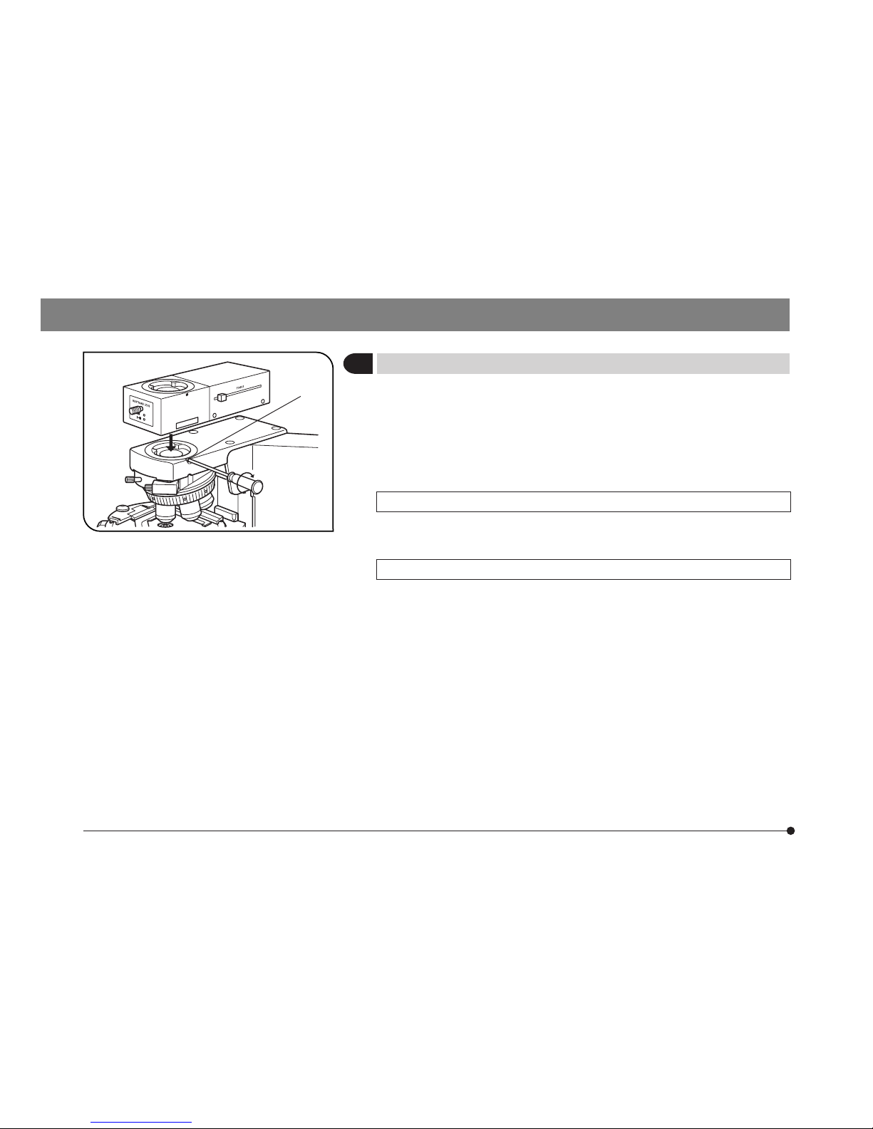
When Using Polarizing Intermediate Attachment (U-CPA)
#Always make sure to mount this unit in such a manner, that it is
parallel to the arm.
Intermediate Attachment for AN360P (U-OPA)
# The position of this intermediate tube can be adjusted later. At this
point, place the tube so the nameplate is toward the rear.
1. Using the Allen screwdriver, loosen the observation tube clamping screw
@ on the microscope frame.
2. Insert the circular dovetail mount at the bottom of the intermediate
attachments into the opening on the microscope frame and clamp
by tightening the clamping screw @.
@
Fig. 6
5
Mounting the Intermediate Attachments (Fig. 6)
8
BX51/52-P,BX41-P
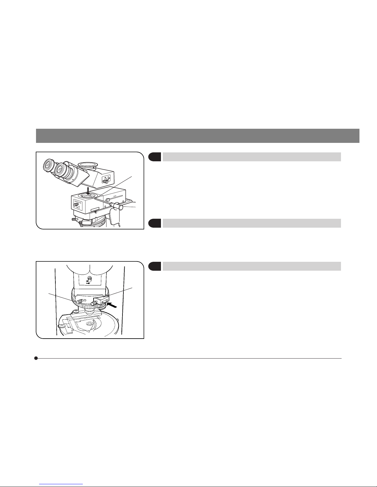
1. Using the Allen screwdriver, fully loosen the observation tube clamping
screw @ on the intermediate attachment.
2. Insert the circular dovetail mount at the bottom of the observation tube
into the opening on the intermediate attachment, placing the observation
tube to point the binocular eyepieces towards the front. Fasten the
observation tube by tightening the clamping screw.
7
Mounting the Eyepieces
Insert the eyepiece with cross lines into the right hand eyepiece sleeve.
Make sure the eyepiece is inserted so that the positioning pin on the
eyepiece is inserted into the groove at the lower end of the sleeve.
1. Loosen the revolving nosepiece clamping knob @ and remove the
dummy slider.
2. Insert the test plate adapter ² and securely tighten the clamping knob
@.
@
@
²
6
Mounting the Observation Tube
(Fig. 7)
8
Mounting the Test Plate Adapter (U-TAD)
(Fig. 8)
Fig. 7
Fig. 8
 Loading...