

Page 1
INSTRUCTIONS
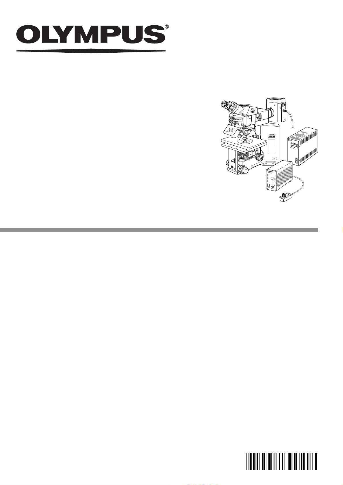
BX51WI
FIXED-STAGE UPRIGHT
MICROSCOPE
This instruction manual is for the Olympus Fixed-Stage Upright Microscope Model BX51WI. To
ensure the safety, obtain optimum performance and to familiarize yourself fully with the use of
this microscope, we recommend that you study this manual thoroughly before operating the
microscope. Retain this instruction manual in an easily accessible place near the work desk for
future reference.
A X 7 6 5 7
Page 2

Page 3

BX51WI
CONTENTS
Correct assembly and adjustments are critical for the microscope to exhibit its full performance. If you are going to
assemble the microscope yourself, please read Chapter 9, “ASSEMBLY” (pages 36 to 42) carefully. For the modules
provided with instruction manuals, also read the assembly procedures in their instruction manuals.
IMPORTANT — Be sure to read this section for safe use of the equipment. —
1 MODULE NOMENCLATURE
2 CONTROLS
TRANSMITTED LIGHT BRIGHTFIELD OBSERVATION PROCEDURE
3
4 USING THE CONTROLS
4-1 Microscope Base, Power Supply Unit (TH4)................................................................................................ 10
1 Controlling the Light Intensity (TH4) 2 Using the Filter Turret
4-2 Focusing Block........................................................................................................................................................................................ 11
1 Using the Pre-focusing Lever 2 Using the Fine Adjustment Fast-Feed Knob
3 Using the Frost Switching Lever
4 Adjusting the Coarse Adjustment Knob Rotation Tension
4-3 Stage (IX-SVL2) ............................................................................................................................................................................. 12, 13
1 Placing the Specimen 2 Moving the Specimen
3 Setting the Grounding 4
5 Using the Light Shield Sheet 6 Lowering the Stage Height
4-4 Revolving Nosepiece .................................................................................................................................................................... 13
1 Switching the Objectives (U-SLRE, WI-SRE3)
4-5 Observation Tube ..................................................................................................................................................................... 14, 15
1 Adjusting the Interpupillary Distance 2 Adjusting the Diopter
3 Using the Eye Shades 4 Using Eyepiece Micrometer Disks
5 Selecting the Light Path of Trinocular Tube
4-6 Condenser .......................................................................................................................................................................................... 16, 17
1 Centering the Condenser (Field Iris Diaphragm, Aperture Iris Diaphragm)
2 Oblique Illumination (WI-OBCD)
4-7 Immersion Objectives .................................................................................................................................................................. 18
1 Using Water Immersion Objectives (Water Immersion Cap for XL Objectives XL-CAP)
Adjusting the X-Axis/Y-Axis Knob Rotation Tension
1-2
3
4-7
8, 9
10-18
Page 4
5 OTHER OBSERVATION METHODS
5-1 Differential Interference Contrast Observation............................................................................... 19-23
1 Attaching the Analyzer 2 Attaching the Polarizer
3 Attaching the DIC Prisms (for Revolving Nosepiece)
4 Attaching the DIC Prisms (for Condenser)
5 Adjusting the Polarizer Position (except the U-UCD8)
6 Observation Method
5-2 Reflected Light Fluorescence Observation................................................................................................... 24
5-3
Infrared Light (IR)/Differential Interference Contrast (DIC) Observation
1 Introduction 2 Attaching the IR Modules
3 DIC Observation Using IR
5-4 Macro Reflected Light Fluorescence Observation ................................................................. 28-30
1 Introduction 2 Attaching the Modules
3 Filter Characteristics of Fluorescence Mirror Units
4 Fabricating Optional Mirror Unit
19-30
............... 24-27
6 TROUBLESHOOTING GUIDE
7 SPECIFICATIONS
8 OPTICAL CHARACTERISTICS
9
ASSEMBLY
PROPER SELECTION OF THE POWER SUPPLY CORD ...................................................................
—
See this section for the replacement of the light bulb. —
10 LAMP HOUSING INSPECTION SHEET
This device complies with the requirements of directive 98/79/EC concerning in vitro diagnostic medical devices. CE marking means the conformity to the directive.
NOTE: This equipment has been tested and found to comply with the limits for a Class A digital device,
pursuant to Part 15 of the FCC Rules. These limits are designed to provide reasonable protection
against harmful interference when the equipment is operated in a commercial environment. This
equipment generates, uses, and can radiate radio frequency energy and, if not installed and used in
accordance with the instruction manual, may cause harmful interference to radio communications.
Operation of this equipment in a residential area is likely to cause harmful interference in which case
the user will be required to correct the interference at his own expense.
31-33
34
35
36-42
43, 44
45
FCC WARNING: Changes or modifications not expressly approved by the party responsible for compliance
could void the user’s authority to operate the equipment.
Page 5
IMPORTANT
This microscope employs a UIS2 (UIS) (Universal Infinity System) optical design, and should be used only
with UIS2 (UIS) eyepieces, objectives and condensers for the BX2 series. (Some of the modules designed
for the BX series are also usable. For details, please consult Olympus or the latest catalogues.)
To obtain comprehensive understanding on the operating procedures, please also read the separately
provided instruction manuals.
Instruction manual
BX51WI
TH4
BX-URA2/BX-RFA
WI-DPMC
WI-XYM/XYS
WI-SSNP
Explanation of transmitted brightfield observation, differential
interference contrast observation and infrared observation
Explanation of the external halogen bulb power supply unit
Explanation of reflected light fluorescence observation
Explanation of the variable-magnification dual-port observation tube
Explanation of the XY mover/bridge stage
Explanation of the swinging-sliding revolving nosepiece
SAFETY PRECAUTIONS
Contents
BX51WI
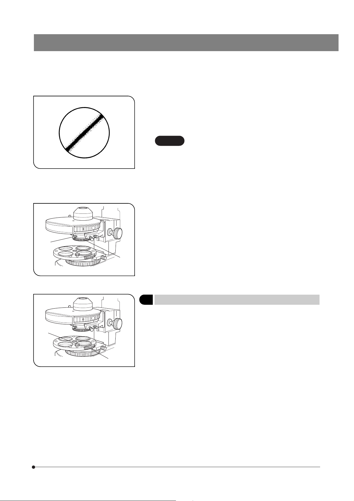
1. After the equipment has been used in an observation of a specimen
²
@
Fig. 1
that is accompanied with a potential of infection, clean the parts
coming in contact with the specimen to prevent infection.
· Moving this product is accompanied with the risk of dropping the
specimen. Be sure to remove the specimen before moving this
product.
· In case the specimen is damaged by erroneous operation, promptly
take the infection prevention measures.
2. Culture liquid or water spilt on the stage, condenser or microscope may
damage the equipment. Immediately wipe the liquid or water off if it is
spilt on them.
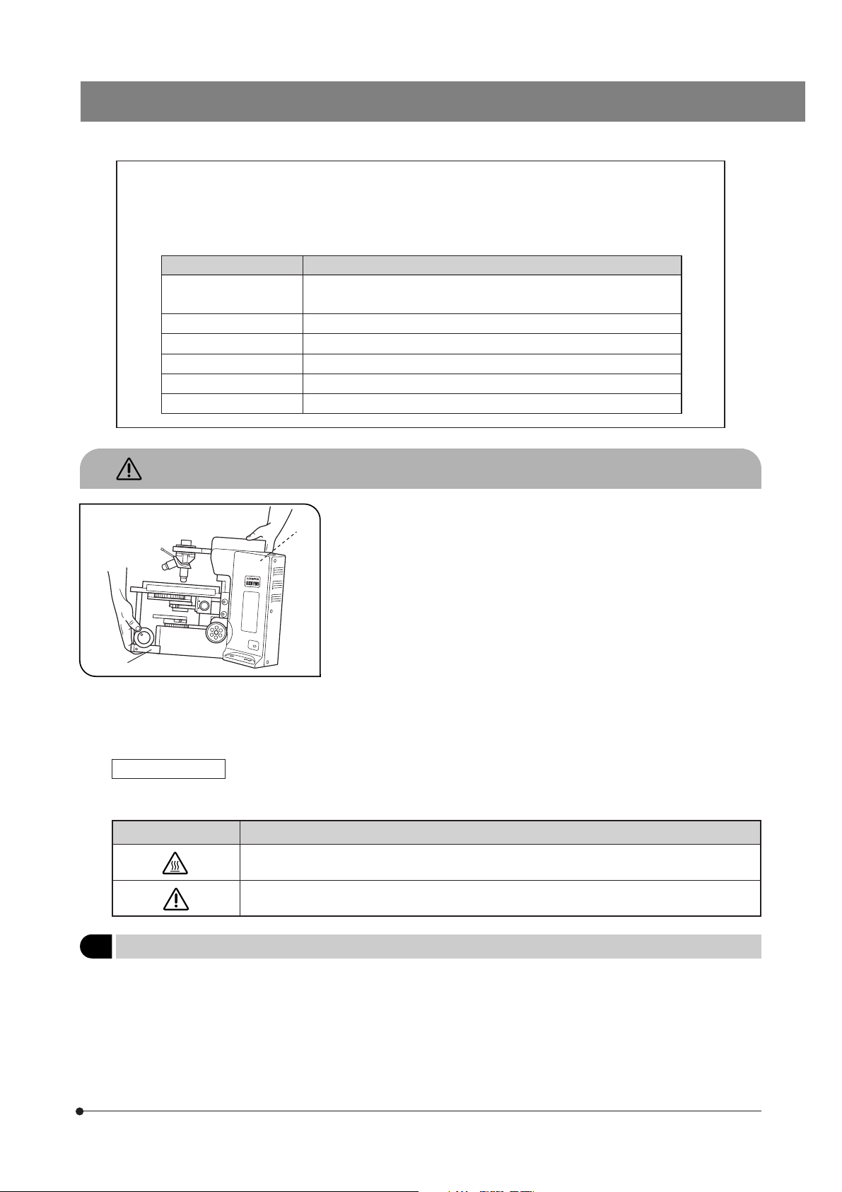
3. When moving the microscope, disconnect the reflected light illuminator,
observation tube and transmitted light lamp housing and carefully carry
the microscope by the base (front edge) @ and the grasping part on the
rear of the arm ² as shown in Fig. 1. (Weight: approx. 15 kg.)
Also be careful against slipping of hands during carrying.
# Damage to the microscope will occur if you grasp it by other parts
including the stage, coarse/fine adjustment knob, etc.
Safety Symbols
The following symbols are found on the microscope. Study the meaning of the symbols and always use the equipment
in the safest possible manner.
Symbol Explanation
Indicates that the surface becomes hot, and should not be touched with bare hands.
Before use, carefully read the instruction manual. Improper use could result in personal injury to
the user and/or damage to the equipment.
1 Getting Ready
1. A microscope is a precision instrument. Handle it with care and avoid subjecting it to sudden or severe impact.
2. The U-SWTR-3 super-widefield observation tube (FN 26.5) cannot be used with the BX51WI microscope.
3. The BX51WI microscope can be used with an intermediate attachment (such as a BX-URA2 or BX-RFA reflected light
illuminator, U-ECA or U-CA magnification changer, etc.).
Two intermediate attachments can be used only in the following conditions:
· The U-CA or U-ECA magnification changer or U-FWO filter wheel can be mounted as the second attachment.
· When a TV adapter with 1X or higher power is used, 2/3-inch CCD TV observation is possible.
· The peripheral areas of the field of view may be obscured or cut off in binocular observation using the U-TR30-2, U-ETR
or U-TR30IR (FN 22) super-widefield observation tube.
1
Page 6
4. In IR (infrared) observation, the U-CA or U-ECA magnification changer can be used only when the U-ETR3 or U-TR30IR
observation is used.
5. In photomicrography with visible light, correct exposure may be impossible if the microscope is set for IR observation.
Be sure to engage the provided IR cut filter (light blue) before photomicrography.
6. When the XLUMPlanFl20XW objective is used, only the U-TV1X-2, U-TVCAC, U-PMTVC2XIR or U-PMTVC4XIR TV adapter
can be used.
7. Do not attempt to remove or loosen the click springs and screws. Otherwise, Olympus can no longer warrant the
performance of the microscope.
The clicking force of the revolving nosepiece has been set weak in order to reduce vibrations during objective switching.
To reproduce the correct click position, switch the objectives gently by operating the lever.
8. Caution for use of the U-ETR3 upright trinocular tube:
When the aperture stop of the condenser is reduced using a reflected light fluorescence illuminator and the LUMPlanFl60XW
objective, part of the observed field of view may be obscured slightly. This is due to the reduction of the light intensity in
the field of view due to the narrow aperture and is not due to a defective optical adjustment of the microscope.
This phenomenon does not affect the photomicrography or TV camera light path.
2 Maintenance and Storage
1. To clean the lenses and other glass components, simply blow dirty away using a commercially available blower and
wipe gently using a piece of cleaning paper (or clean gauze).
If a lens is stained with fingerprints or oil smudges, wipe it gauze slightly moistened with commercially available absolute
alcohol.
Since the absolute alcohol is highly flammable, it must be handled carefully.
Be sure to keep it away from open flames or potential sources of electrical sparks –– for example, electrical
equipment that is being switched on or off.
Also remember to always use it only in a well-ventilated room.
2. Do not attempt to use organic solvents to clean the microscope components other than the glass components. To clean
them, use a lint-free, soft cloth slightly moistened with a diluted neutral detergent.
3. Never attempt to disassemble any part of the microscope.
4. When not using the microscope, make sure to set the main switch to “ ” (OFF), confirm that the lamp housing is cool
enough and cover the microscope with the provided dust cover.
5. When disposing of this unit, check the regulations and rules of your local government and be sure to observe them.
3 Warning Indication
A warning sticker is attached to a part where special precaution is required when handling and using the system. Always
heed the warning.
Warning indication
position
Lamp housing (U-LH100-3/U-LH100IR)
(Warning against high temperature)
4 Caution
If the microscope is used in a manner not specified by this manual, the safety of the user may be imperiled. In addition,
the equipment may also be damaged. Always use the equipment as outlined in this instruction manual.
The following symbols are used to set off text in this instruction manual.
: Indicates that failure to follow the instructions in the warning could result in bodily harm to the
user and/or damage to equipment (including objects in the vicinity of the equipment).
# : Indicates that failure to follow the instructions could result in damage to equipment.
} : Indicates commentary (for ease of operation and maintenance).
Intended use
5
This instrument has been designed to be used to observe magnified images of specimens in routine and research
applications.
Do not use this instrument for any purpose other than its intended use.
2
Page 7
BX51WI
MODULE NOMENCLATURE
}The modules shown below are only the representative modules. As there are other modules which can be combined with
the microscope but are not shown below, please also refer to the latest Olympus catalogues or your dealer.
Transmitted Arm BX-ARM
or Reflected Light Fluorescence Illuminator
· BX-URA2
· BX-RFA
Trinocular Observation Tube
· U-TR30-2 (FN 22)
· U-TR30IR (FN 22)
· U-ETR3 (FN 22)
Revolving Nosepiece
· WI-SRE3
· WI-SNPXLU2
· U-SLRE
Revolving Arm
WI-NPA
Cross Stage
IX-SVL2
or commercially
available bridge
stage
Fixed-Stage Adapter
WI-FSH
Reflected Light Mercury Lamp Housing
· U-LH100HG
· U-LH100HGAPO
Microscope Frame BX51WIF
Power Supply Unit
U-RFL-T
Transmitted Light Lamp Housing
· U-LH100-3
· U-LH100IR
Condenser
· WI-UCD
· WI-DICD
· WI-OBCD
· U-UCD8
· U-SC3
· U-AAC
· U-AC2
Power Supply Unit (for Halogen Bulb)
TH4
Hand Switch TH4-HS
Objective
· MPLN5X
· UMPlanFLN10XW/20XW
· LUMPlanFLN40XW/60XW
· LUMFLN60XW
· LUMPlanFl100XW
· XLUMPlanFI20XW
(exclusively for use with the WI-SNPXLU2)
· XLFluor2X/340
(exclusively for use with the U-SLRE)
· XLFluor4X/340
(exclusively for use with the U-SLRE)
3
Page 8
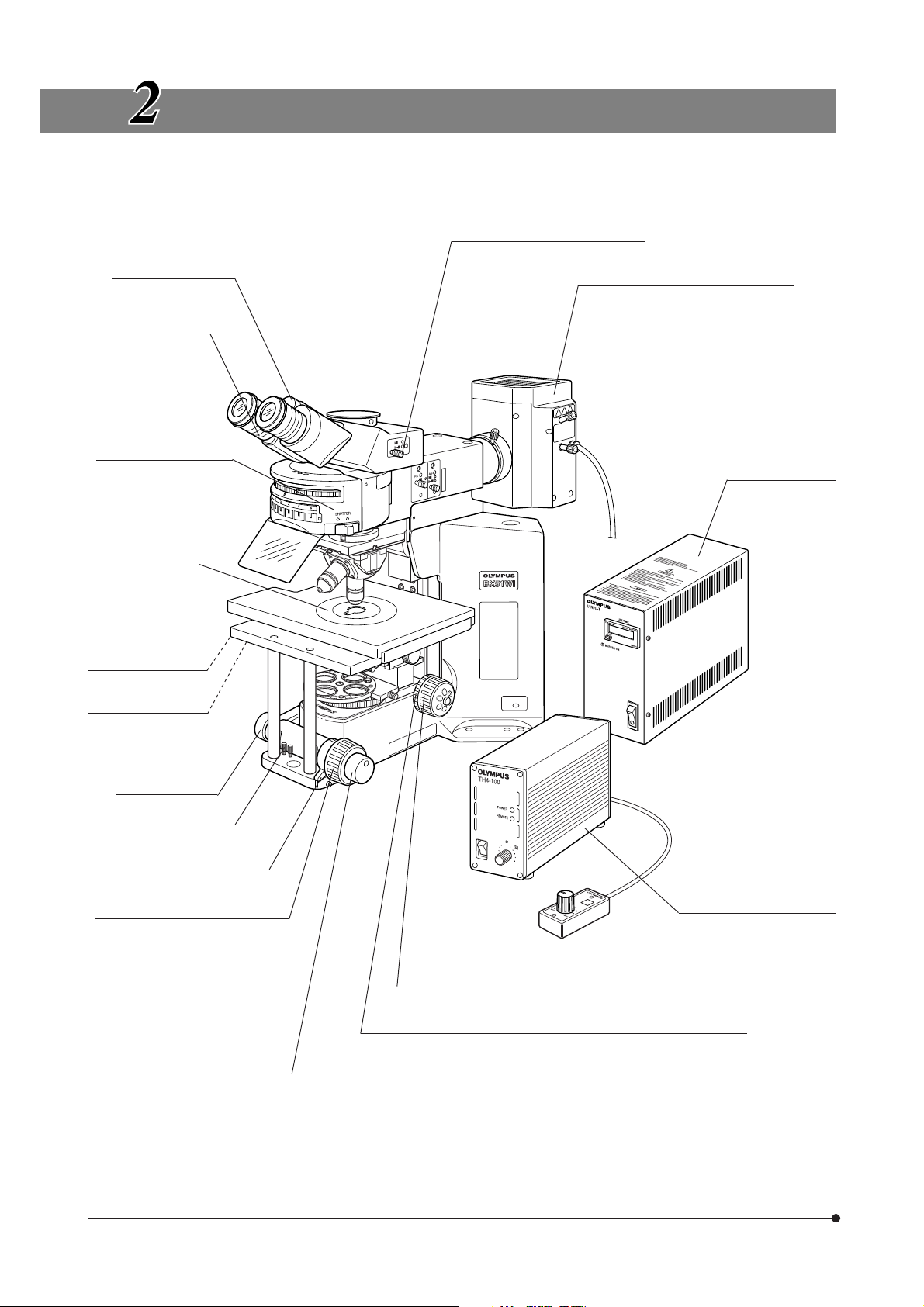
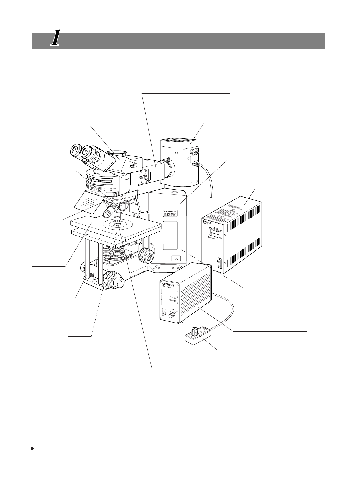
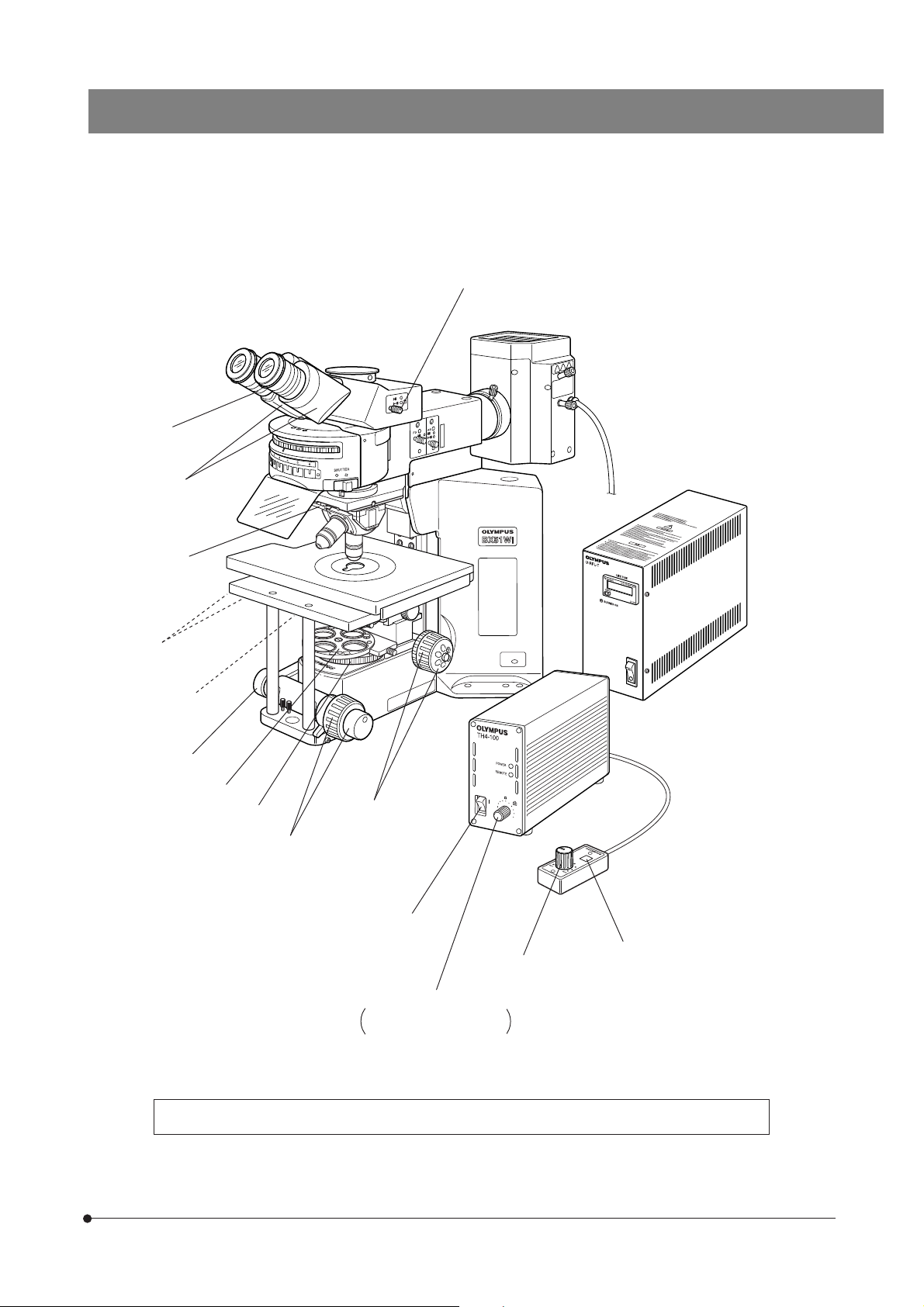
CONTROLS
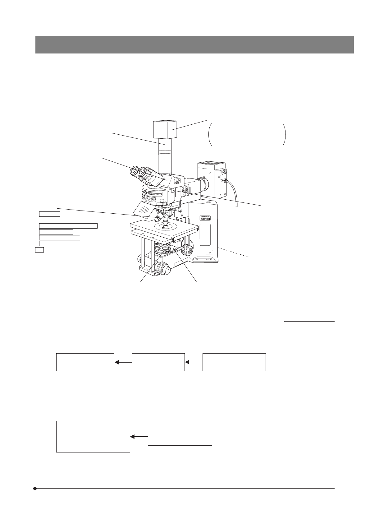
}If you have not yet assembled the microscope, read Chapter 9, “ASSEMBLY” (pages 36 to 42).
Light path selector knob (Page 15)
Interpupillary distance
scale (Page 14)
Diopter adjustment
ring (Page 14)
Reflected light
fluorescence illuminator
(See the separately
provided instruction
manual.)
Stage center plate
Reflected light mercury lamp housing
(See the separately provided instruction
manual.)
Power supply unit
(See the separately
provided instruction
manual.)
Y-axis knob (Page 12)
X-axis knob (Page 12)
Rubber cap for fine
adjustment knob
(Page 11)
Centering knob
(Accommodation position)
Pre-focusing lever (Page 11)
Coarse adjustment knob (Page 11)
Power supply unit
(See the separately provided
instruction manual.)
Coarse adjustment knob (Page 11)
Coarse adjustment knob rotation tension adjustment ring (Page 11)
Fine adjustment knob (Page 11)
4
}The descriptions on the filter turret, revolving nosepiece, condenser, etc. will be given in the subsequent pages.
Page 9
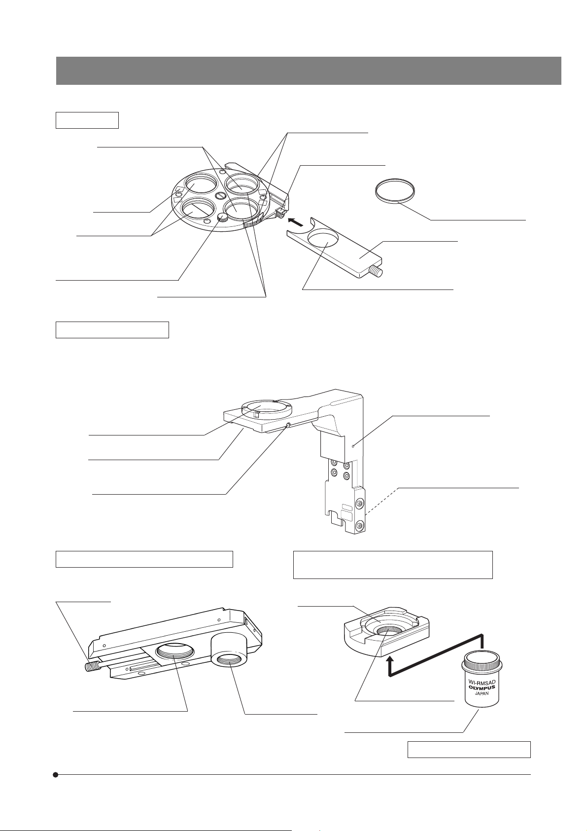
BX51WI
Filter Turret
Polarizer positions (Page 19)*
Accepts the 32PO or 32POIR.
Indication label
attaching frame
Filter positions
Accepts 32 mm filters
with thickness of no
more than 6 mm.
Polarizer clamping knob (Page 19)
Polarizer push ring (Page 10)
Made of white plastic
Polarizer rotating dials
(Page 23)
Slider insertion/removal
stopper (Page 10)
IR filter insertion position
Accepts the 32BP775, 32IR900 or a 32 mm
filter with thickness of no more than 5.3 mm.
* Accepts the combination of a
polarizer push ring and a 32 mm
filter. The thickness should be no
more than 6 mm.
Filter frame reinforcing ring
Filter slider (Page 10)
Revolving Arm WI-NPA
# Note that the revolving arm can be mounted only before the reflected light illuminator is mounted or before the
transmitted light arm and IX-SVL2 stage are mounted (page 38).
}This revolving arm accepts the U-SLRE, WI-SNPXLU2 or WI-SRE3 revolving nosepiece.
(Page 38)
Light shield tube retaining screw
Revolving nosepiece mount dovetail
Revolving nosepiece clamping screw
Sliding Revolving Nosepiece U-SLRE
Switching lever
XLFluor objective mount screw
M 34 mm, pitch 1 mm
Single-Position Revolving Nosepiece XLU
WI-SNPXLU2
DIC mount hole
UIS2 (UIS) objective
mount screw
Grounding screw hole (M3)
Microscope frame mount dovetail
(Page 20)
XLU objective mount screw
M 25 mm, pitch 0.75 mm
UIS2 (UIS) objective mount screw
RMS Adapter WI-RMSAD
5
Page 10
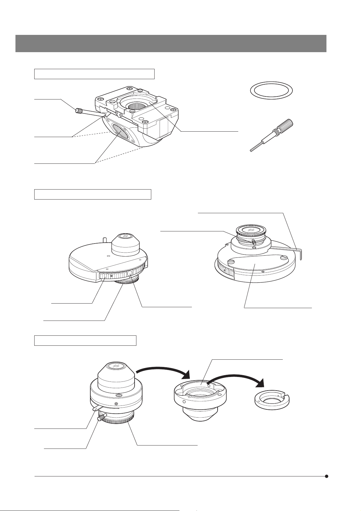
Swinging Revolving Nosepiece WI-SRE3
Swing lever
Confocality correction washers
(Kinds of thickness: 10, 30 and
50 μm; three washers per kind)
Centering screw
UIS2 (UIS) objective mount
screws
Long-WD Universal Condenser WI-UCD
Turret (4 positions)
Quarter-wave plate rotation
ring (Page 23)
DIC mount hole (Page 20)
Quarter-wave plate clamping
knob
Optical element index
mount (Page 21)
Centering knob
Aperture iris diaphragm lever (Page 17)
DIC prism replacement cover
Long-WD DIC Condenser WI-DICD
Aperture iris diaphragm
lever (Page 17)
Quarter-wave plate
clamping knob
6
DIC prism (large) mount position
DIC prism (small) adapter
Quarter-wave plate rotation
ring (Page 23)
Page 11
BX51WI
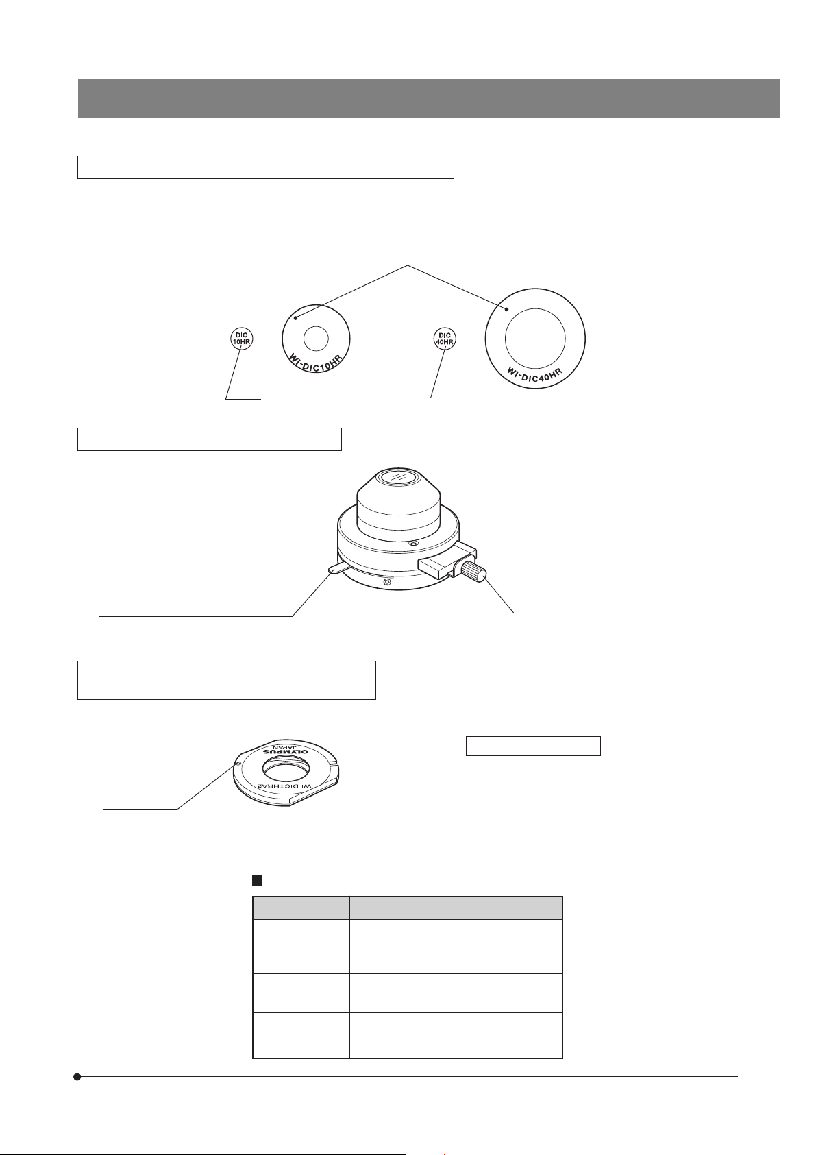
Differential Interference Contrast Prisms (For Condenser)
}The WI-UCD condenser accepts two large and two small DIC prisms while the WI-DICD condenser accepts one large or
small DIC prism.
When selecting the brightfield (BF) light path using the WI-UCD, leave one DIC prism (large) mount position empty.
Positioning indices
· WI-DIC10HR
· WI-DIC20HR
Index
Long-WD Oblique Condenser WI-OBCD
Aperture iris diaphragm lever (Page 17)
High-Resolution DIC Prism A WI-DICTHRA2
DIC Prism WI-DICT2
· WI-DIC40HR
· WI-DIC60HR
· U-LDPXLU20HR
Index
Oblique iris insertion/removal knob (Page 17)
}This prism can be mounted in the DIC prism position
of the WI-SNPXLU2 or WI-SRE3.
Positioning pin
Applicable condensers
WI-DICTHRA2: WI-UCD, WI-DICD
WI-DICT2: U-UCD8
Condensers and Applicable Objective Magnifications
Condenser
WI-UCD
WI-DICD
WI-OBCD
U-UCD8
U-SC3
U-AAC 10X or more
U-AC2 5X or more
Applicable Objective Magnification
5X or more
2X or more
7
Page 12
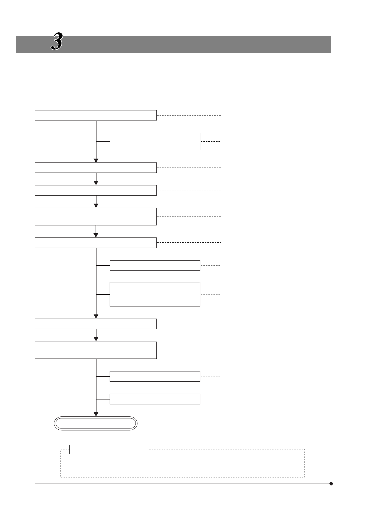
TRANSMITTED LIGHT BRIGHTFIELD
OBSERVATION PROCEDURE
}The following flow shows the operating procedure for the transmitted light brightfield observation which is the basic obser-
vation method of this microscope. The operating procedures for DIC observation, fluorescence DIC observation and IR DIC
observation will be described separately in Chapter 5, “OTHER OBSERVATION METHODS” on page 19.
Set the main switch to “ I ” (ON).
Disengage the filter from the light
path.
Select the binocular light path.
Place the specimen on the stage.
Engage a low-magnification objective in the
light path.
Bring the specimen in focus.
Adjust the brightness.
(Controls Used)
@Main switch (P. 10)
²Lamp ON-OFF switch (P. 10)
(Only when the hand switch is used)
³Filter turret (P. 10)
|Light path selector knob (P. 15)
ƒX-axis and Y-axis knobs (P. 12)
…Swing lever (P. 13)
†Coarse/fine adjustment knobs (P. 11)
‡Light intensity control knob (P. 10)
(Page)
Adjust the interpupillary distance.
Adjust the diopter.
Adjust the light axis.
Adjust the aperture iris and field iris diaphragms.
Engage the objective to be used in the light
path and bring the specimen in focus.
Engage the required filters.
Adjust the brightness.
Start observation.
Tip for microscope operation
ŠBinocular tube (P. 14)
‰Diopter adjustment ring (P. 14)
‹Condenser height adjustment knob (P. 16)
ŒCondenser centering knob (P. 16)
™Aperture iris diaphragm lever (P. 17)
šField iris diaphragm ring (P. 16)
…Swing lever (P. 13)
†Coarse/fine adjustment knobs (P. 11)
³Filter turret (P. 10)
‡Light intensity control knob (P. 10)
8
In patch-clamp testing, switch the microscope controls cautiously and gently so that the patch
electrodes do not slip off.
Page 13
‰
BX51WI
|
Š
…
ƒ
‹Œ™
†
³
š
†
†
@
²
‡
‡
Used only when the hand
switch is not connected
} Make a photocopy of the observation procedure pages and post it near your microscope.
9
Page 14
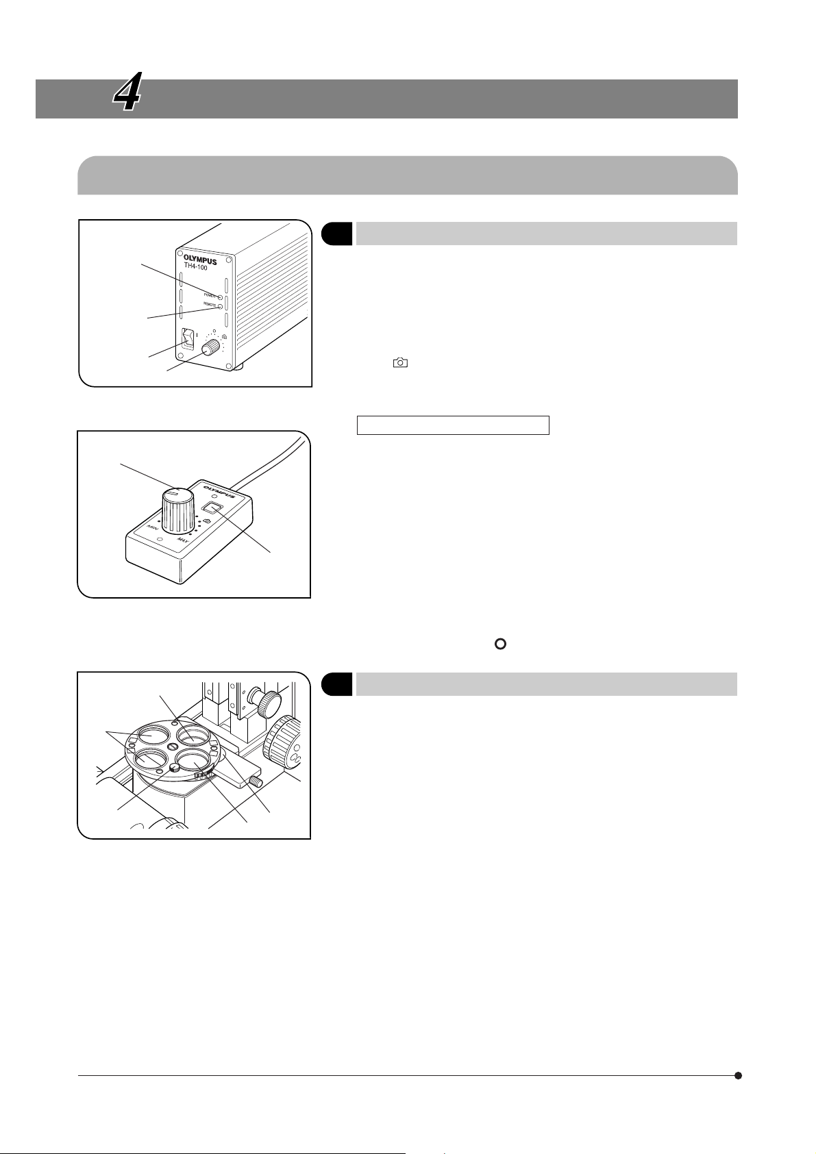
USING THE CONTROLS
4-1 Microscope Base, Power Supply Unit (TH4)
ƒ
³
|
²
@
Fig. 2
Fig. 3
…
1 Controlling the Light Intensity (TH4)
}See the separately provided instruction manual for details.
1. Make sure that the light intensity control knob @ is set to MIN (minimum
voltage), then set the main switch ² to “ I ” (ON). (The POWER LED ³
should light up.)
2. Turn the knob @ clockwise toward MAX (maximum voltage) to increase
the intensity and brightness.
}The marking indicates the position where the optimum daylight for
color photography is obtained when the LBD filter is engaged in the light
path.
Operation Using the Hand Switch
}When the hand switch is connected (when the REMOTE LED | is lit), the
light intensity control knob @ is defeated and only the light intensity
control knob ƒ of the hand switch can be used.
The hand switch is provided with double-side adhesive tape so that it
can be attached onto a convenient position for operation.
1. After setting the main switch ² to “ I ” (ON), press the lamp ON-OFF switch
… to ON and adjust the brightness with the intensity control knob ƒ.
2. To turn the lamp OFF, press the lap ON/OFF switch … again to OFF.
#The lighting of the REMOTE LED | indicates that the hand switch is
standing by. The hand switch consumes a power of about 2.5 W
when it stands by.
When the system is not to be used for a lone period, be sure to set
the main switch ² to “ ” (OFF).
(Figs. 2 & 3)
³
ƒ
@
Fig. 4
²
|
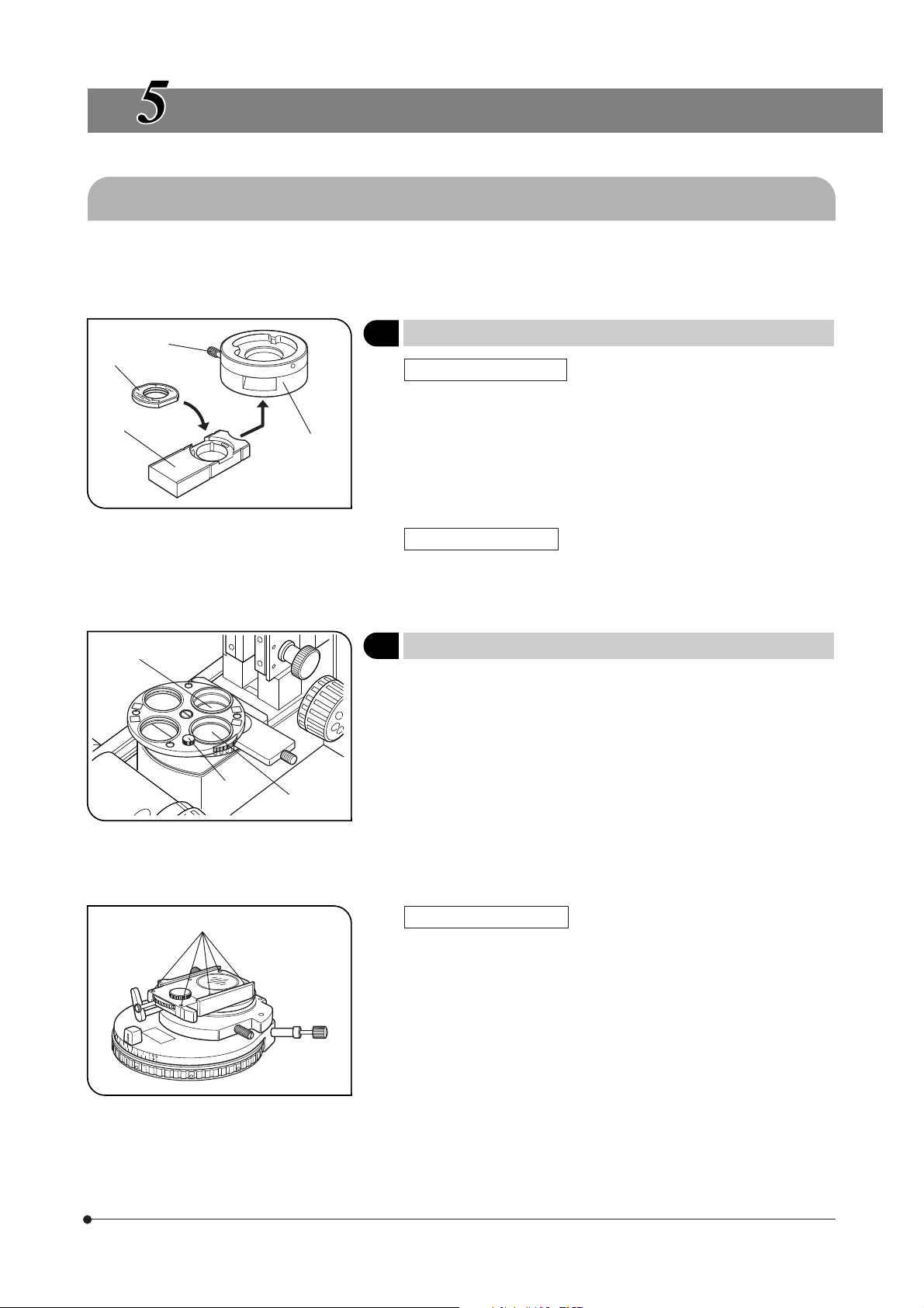
2 Using the Filter Turret
}Filters with a diameter of 32 mm can be inserted in positions @ to |.
1. Filter positions @ and ² are rotatable. When the 32PO polarizer or 32POIR
polarizer is placed in either position, the polarizer or filter can be fixed by
using the push ring (made of white plastic).
}When filter position @ is engaged in the light path, the rotation fixing
knob ƒ comes at the front where the operation is easy.
2. Filter position ³ accepts any type of 32 mm filter.
#When using two filters together, the thickness of the lower filter should
be no more than 2 mm. Otherwise, the upper filter may drop during
rotation.
3. Filter position | accepts the 32BP775 or 32IR900 filter. As the filter cannot be inserted unless the filter slider is removed, remove it by releasing
the insertion/removal stopper below the slider and loosening the slider
clamping screw using the provided Allen screwdriver.
(Fig. 4)
10
Page 15
4-2 Focusing Block
BX51WI
@
²
@
Fig. 5
Fig. 6
²
³
1 Using the Pre-focusing Lever
}The pre-focusing lever prevents collision between the specimen and
objective and simplifies the focusing operation. After bringing the
specimen into approximate focus with the coarse adjustment knob, turn
the pre-focusing lever @ in the direction of the arrow to lock it. Hereafter,
the lower limit of the coarse adjustment will be limited at the position
where the lever is locked. When bringing a specimen in focus, approximate
focus can be obtained by simply lowering the coarse adjustment to the
stopper position so all you have to do more is control the fine adjustment
knob.
}The up/down movement using the fine adjustment knob is not limited.
# When the pre-focusing lever is locked, the coarse adjustment stroke
is limited by the mechanism and it cannot reach the previous upper
limit. If you want to control the coarse adjustment knob to the previous
upper limit, unlock the pre-focusing lever.
2 Using the Fine Adjustment Fast-Feed Knob
}Fine focusing is usually possible while the rubber cap @ is attached.
However, when it is desirable to allow the fine adjustment knob to vary
focusing by a large amount, though this is not be as large as with the
coarse adjustment knob, the rubber cap can be removed and the provided fine adjustment fast-feed knob attached in place.
}If you remove the knob by loosening the screw clamping the fine adjust-
ment knob ³ from the opposite side, the fine adjustment can be controlled using the tip or thick of your finger.
(Fig. 5)
(Fig. 6)
@
Fig. 7
3 Using the Frost Switching Lever
}Low observation light can be brightened by turning the frost switching
lever @ which controls the built-in frost filter, in the direction of the arrow.
However, although the brightness is increased, irregularity in lighting may
also increase.
4
Adjusting the Coarse Adjustment Knob Rotation Tension
# Do not adjust the coarse adjustment knob rotation tension adjust-
ment ring (² in Fig. 5) because the belt interlocking of the ring with
the coarse adjustment knob on the front has been adjusted at the
factory. If the tension is varied, the accuracy of the pre-focusing lever
will deteriorate.
(Fig. 7)
(Fig. 5)
11
Page 16
4-3 Stage (IX-SVL2)
@
²
Fig. 8
Fig. 9
1 Placing the Specimen
1. Place the specimen on the center of the stage.
}The optional stage center plate (IX-CP50) makes it possible to observe a
wide range of a big petri dish, etc. (Central hole diameter: 50 mm)
2 Moving the Specimen
1. The specimen can be moved by turning the X-axis knob @ and Y-axis
knob ².
The movement strokes are 50 mm (X-axis) x 43 mm (Y-axis).
(Fig. 8)
(Fig. 9)
Fig. 10
Fig. 11
@
@
²
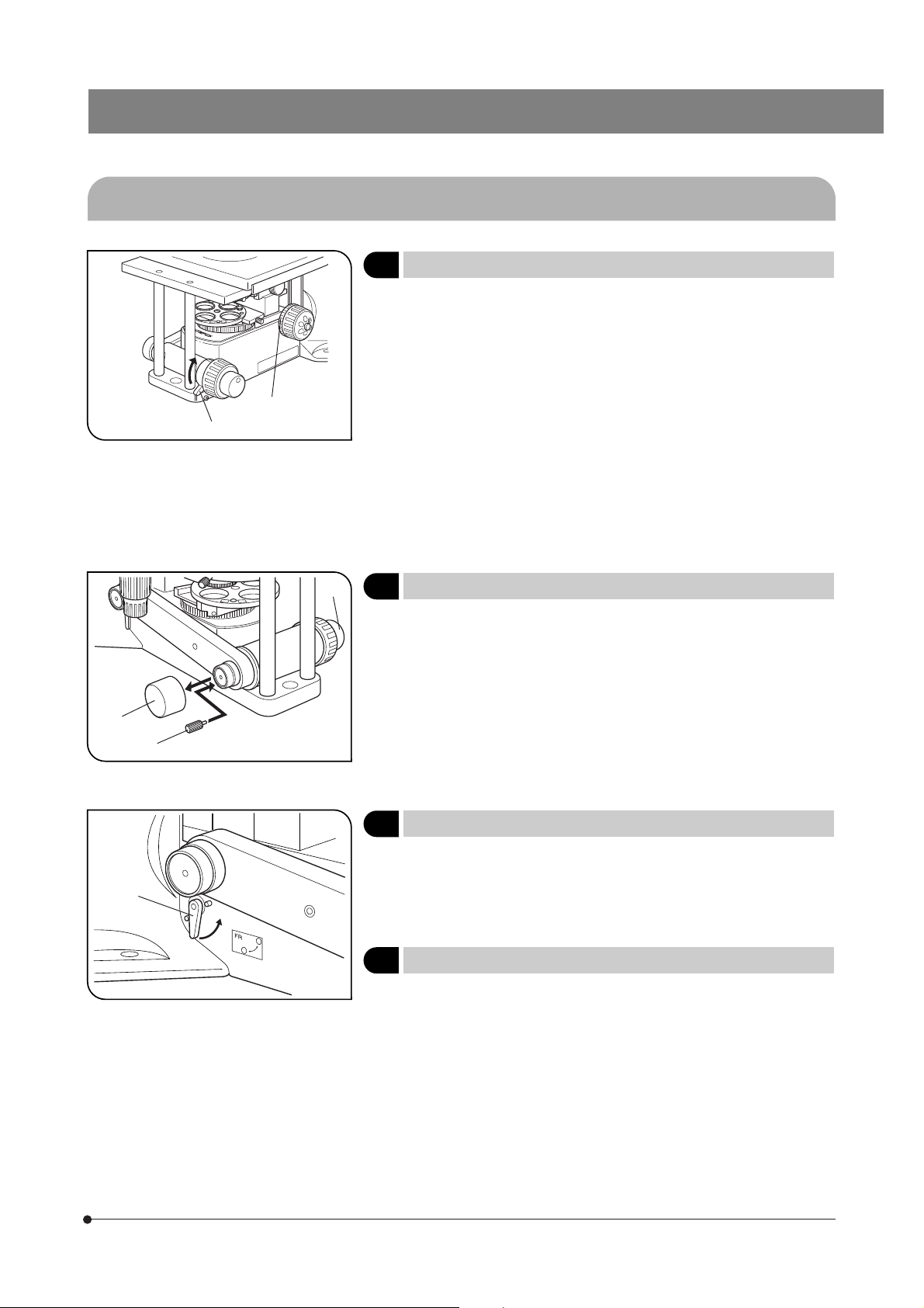
3 Setting the Grounding
}In case of electrical physiological experiment, etc., the specimen can be
grounded from the stage.
Prepare a grounding wire @ and M4 screw ² and attach grounding as
shown in Fig. 10.
# The screw hole may sometimes be stuck by paint, etc. In such a case,
screw in the M4 screw a few times to expose the metallic thread
inside the screw hole and improve the contact before attaching the
grounding wire firmly.
4
Adjusting the X-Axis/Y-Axis Knob Rotation Tension
}The rotation tension of the X-axis and Y-axis knobs can be adjusted
independently.
1. Loosen the 2 set screws @ of a knob using the provided Allen wrench,
hold the stage so that it will not move, then turn the knob to adjust the
tension. Turning it in the direction of the arrow increases the tension and
turning in the opposite direction decreases the tension.
2. After adjustment, tighten the set screws firmly.
# If the tension of a knob is too heavy or too light, skipping or returning of
image may occur during the stage movement.
(Fig. 10)
(Fig. 11)
12
Page 17

BX51WI
(Fig. 12)
Fig. 12
@
5 Using the Light Shield Sheet
# The light shield sheet provided with the reflected light fluorescence
illuminator is too small to be used with the BX51WI. Always use the
light shield sheet provided with the BX51WI microscope frame.
}During fluorescence observation using a low-magnification objective, the
fluorescence image may be deteriorated due to light reflected from the
condenser or the surroundings. In this case, use the light shield sheet.
1. Lower the condenser to the lower limit position using the condenser
height adjustment knob.
2. Insert the light shied sheet all the way into the gap between the upper
and lower stages on the side of the stage (IX-SVL2).
# If the condenser is lowered insufficiently, the sheet cannot be in-
serted into the normal position and the light shielding effect cannot
be obtained.
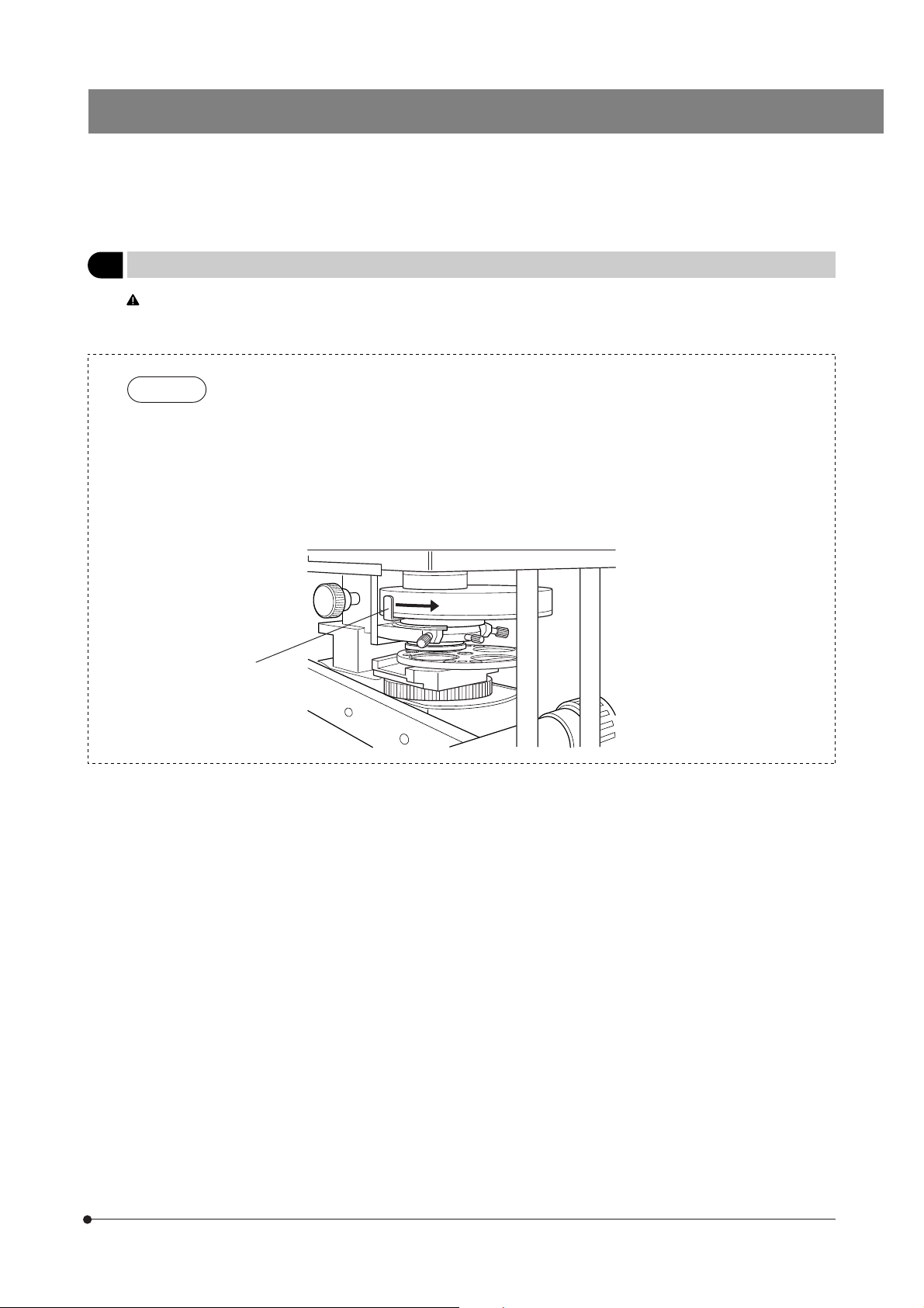
6 Lowering the Stage Height
}The stage can be lowered by 50 mm by removing the condenser holder.
See page 42 for details.
4-4 Revolving Nosepiece
If the petri dish in use is filled with liquid, it may splash when the objective is switched. As such liquids are sometimes
toxic, be sure to move the revolving nosepiece away from the petri dish before switching the objective.
Even after the revolving nosepiece has been moved, re-focusing is easy by making use of the pre-focusing lever (page 11).
@
@
Fig. 13
Fig. 14
1
Switching the Objectives (U-SLRE, WI-SRE3)
}The clicking force of the revolving nosepiece has been set weak in order
to reduce vibrations during objective switching.
To reproduce the correct click position, switch the objectives gently by
operating the lever.
Sliding Revolving Nosepiece U-SLRE
Switch the objective by holding the objective switching lever @ and
gently moving it back and forth.
}By attaching the objective switching lever @ on the opposite side, a UIS
objective can be positioned on the front side of the microscope.
Sliding Revolving Nosepiece WI-SRE3
Switch objectives by gently puling up or pushing down the swing
lever @.
Pull up or push down the swing lever gently until it hits the revolving
nosepiece’s stopper.
(Figs. 13 & 14)
13
Page 18

4-5 Observation Tube
²
Fig. 15
Fig. 16
@
1 Adjusting the Interpupillary Distance
While looking through the eyepieces, adjust for binocular vision until the
left and right fields of view coincide completely. The index dot · indicates
the interpupillary distance.
}Note your interpupillary distance so that it can be quickly duplicated.
2 Adjusting the Diopter
1. Looking through the eyepiece without the diopter adjustment ring, rotate
the coarse and fine adjustment knobs to bring the specimen into focus.
2. Looking through the eyepiece sleeve with the diopter adjustment ring @,
turn only the ring to focus on the specimen. (Fig. 16)
(Figs. 16 & 17)
(Fig. 15)
Fig. 17
Fig. 18
Using a Finder Eyepiece
1. Looking through the right eyepiece with your right eye, turn the top of the
eyepiece ² until a clearly defined double crosslines can be seen in the
field of view. (Figs. 16 & 17)
2. Looking through the right eyepiece, rotate the coarse and fine adjustment knobs to bring the specimen and double crosslines into simultaneous focus.
3. Looking through the left eyepiece with your left eye, turn the diopter
adjustment ring @ to focus on the specimen.
3 Using the Eye Shades
When Wearing Eyeglasses
Use with the eye shades in the normal, folded-down position. This will
prevent the eyeglasses from being scratched.
When Not Wearing Eyeglasses
Extend the folded eye shades in the direction of the arrow to prevent
extraneous light from entering between the eyepieces and eyes.
(Fig. 18)
14
Page 19
BX51WI
Fig. 19
Fig. 20
@
²
@
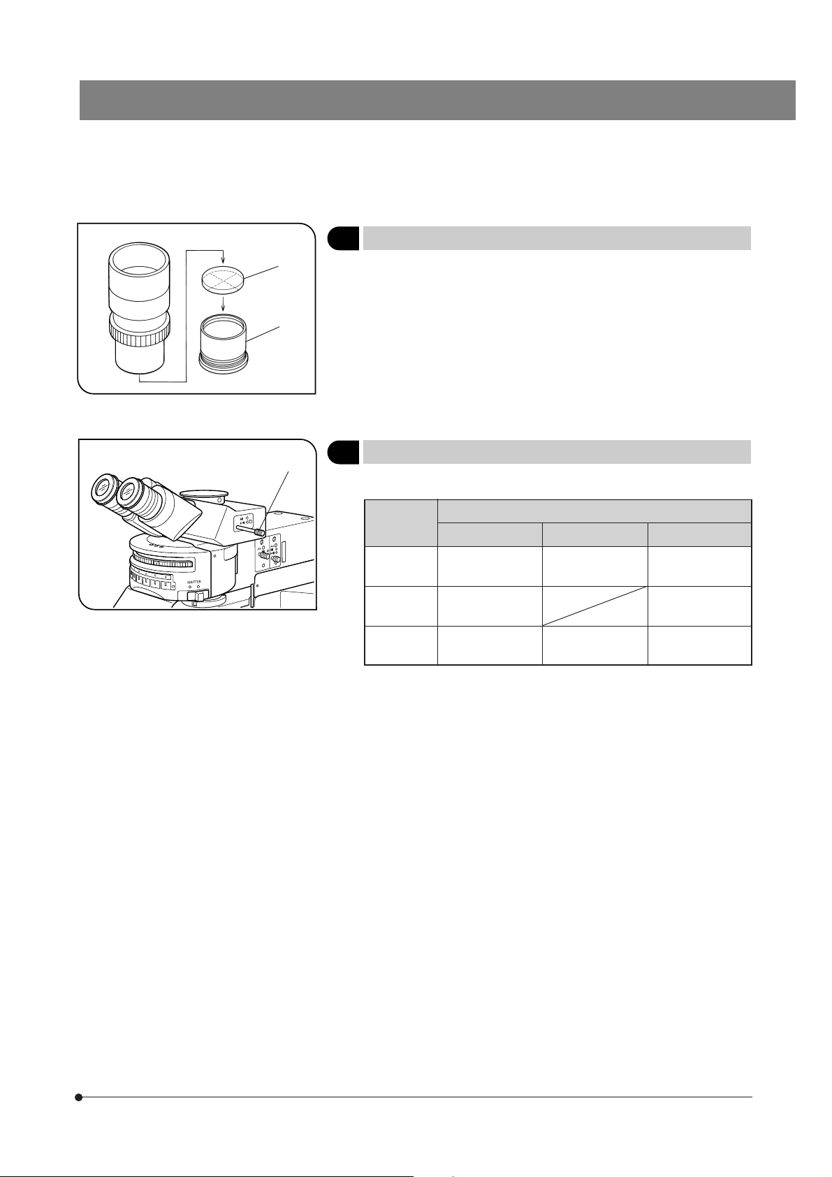
4 Using Eyepiece Micrometer Disks
Eyepiece micrometer disks can be inserted into the WHN10X-H (or
WHN10X) eyepieces.
However, if the eyepiece does not have the helicoid adjustment facility
and your eyesight is poor, you may have difficulties in focusing on the
eyepiece micrometer disk. In this case, it is recommended to look into
the eyepiece through your eyeglasses.
Use 24 mm dia. x 1.5 mm micrometer disks.
Following Fig. 19, remove the micrometer mounting frame ² from the
eyepiece and place a micrometer disk @ into the mounting frame.
Re-attach the micrometer mounting frame in the original position.
5
Selecting the Light Path of Trinocular Tube
Slide the light path selector knob @ to select the desired light path.
Trinocular
Tube
U-TR30-2 Binocular 100% TV, photo 100%
U-ETR3 Binocular 100% TV, photo 100%
Pushed In Intermediate Pulled Out
Light Path Selector Position
Binocular 20%,
TV, photo 80%
(Fig. 19)
(Fig. 20)
U-TR30IR Binocular 100% Shutter TV, photo 100%
15
Page 20
4-6 Condenser
@
|
Fig. 21
Fig. 22
²
³
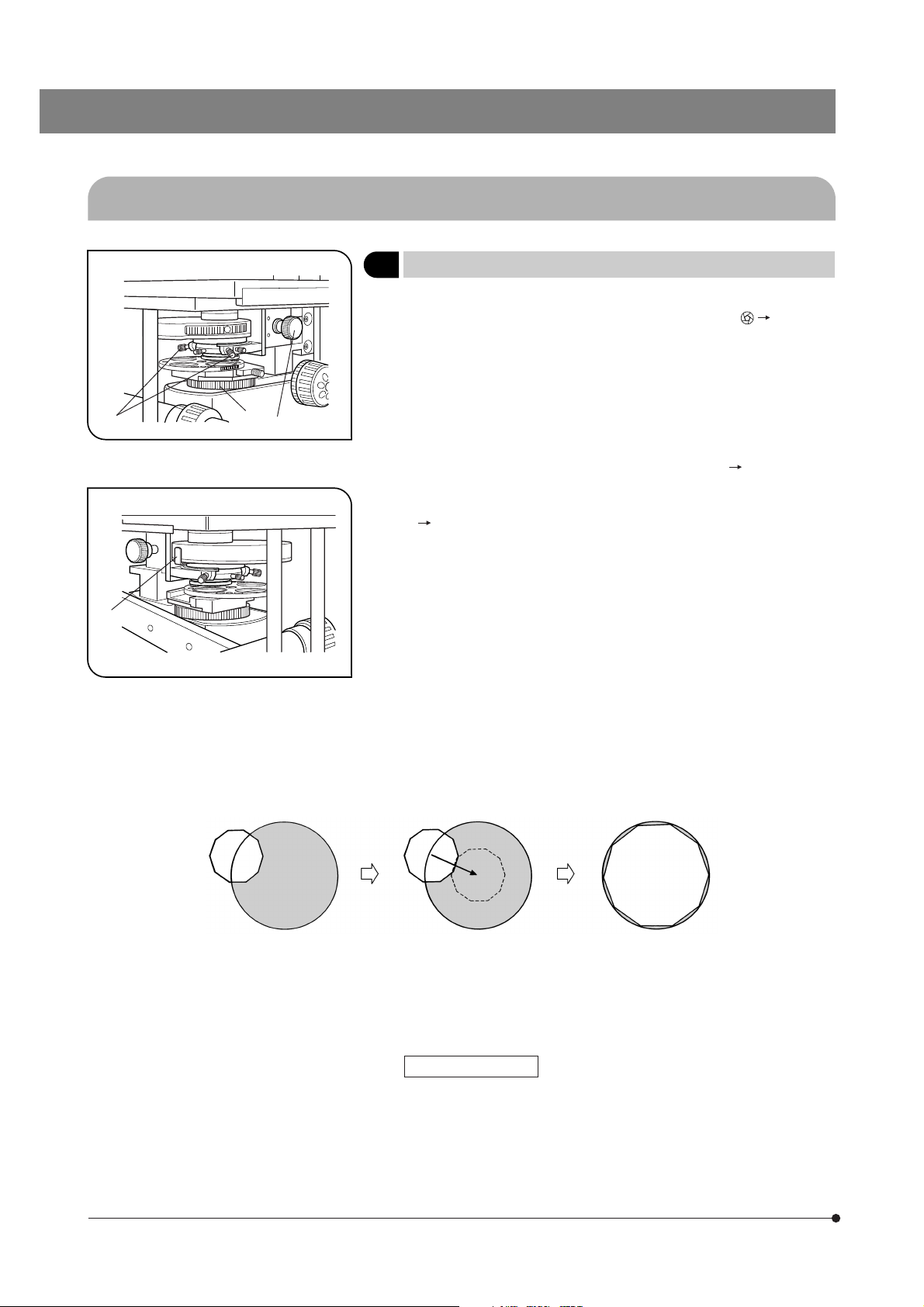
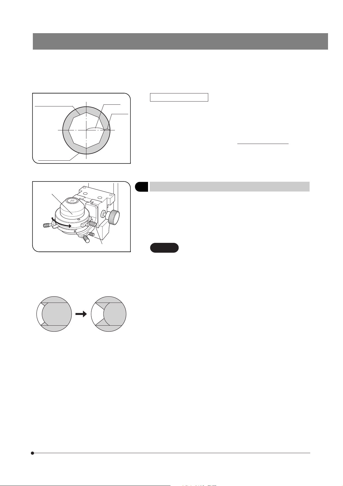
1 Centering the Condenser
1. Set the aperture iris diaphragm lever @ to the open position. (Fig. 22)
2. Set the field iris diaphragm ring ² to the open position ( ¦). (Fig. 21)
3. Focus on the specimen using the 10X objective.
4. Close the field iris diaphragm ring ² so that the diaphragm image comes
inside the field of view.
5. Manipulate the condenser height adjustment knob ³ to focus on the
diaphragm image.
6. While opening the field iris diaphragm gradually, turn the two condenser
centering screws | on the condenser holder to move the iris diaphragm
image to the center of the field of view. (Fig. 21, Fig. A Fig. B).
7. Gradually open the field iris diaphragm. The condenser is properly centered if the iris image is centered and inscribed in the field of view (Fig. B
Fig. C).
}During actual use, open the field diaphragm slightly until its image cir-
cumscribes the field of view.
(Figs. 21 & 22)
16
Fig. A Fig. B Fig. C
Field Iris Diaphragm
The field iris diaphragm restricts the diameter of the beam of light entering the objective and thus excludes extraneous light, improving image
contrast. The diameter of the field iris should be adjusted for objective
magnification to the extent that it just circumscribes the field of view.
Page 21
BX51WI
Aperture iris
diaphragm image
Objective pupil
²
Fig. 23
Fig. 24
70-80%
@
30-20%
Aperture Iris Diaphragm
· The aperture iris diaphragm determines the numerical aperture of the
illumination system. Matching the numerical aperture of the illumination
system with that of the objective provides better image resolution and
contrast, and also increases the depth of focus.
· Since the contrast of microscope specimens is ordinarily low, setting the
condenser aperture iris diaphragm to between 70% and 80% of the NA
of the objective in use is usually recommended. If necessary, adjust the
ratio by removing the eyepieces and looking into the eyepiece sleeve
while adjusting the aperture iris diaphragm lever @ until the image shown
in Fig. 23 is seen. (Fig. 22)
2 Oblique Illumination (WI-OBCD)
}The shading and 3D feeling of the specimen can be adjusted by varying
the width and orientation of the area subjected to oblique illumination.
This is possible with objectives from 5X to 100X.
# When the XLUMPlanFI20XW objective is used, the effects of oblique
illumination cannot be manifested fully due to the high NA (0.95) of
the objective.
Important
The oblique illumination presupposes that the field iris
image is focused correctly.
Before proceeding to the following, pull out the oblique
iris insertion/removal knob @ and bring the field iris
image in focus (this is the same operation as that described on page 16).
(Figs. 24 & 25)
Fig. 25
1. Push in the oblique iris insertion/removal knob @.
2. Turn the knob @ to adjust the width of the area illuminated by oblique
illumination. (Fig. 25)
3. Adjust the orientation of the oblique illumination by turning the top part
² of the condenser.
}Pull out the oblique iris insertion/removal knob when using the condenser
as usual.
The width of the oblique illumination area is maintained even after the
insertion/removal knob @ has been pulled out, so the same condition
can be reproduced the next time the knob is pushed in.
17
Page 22

4-7 Immersion Objectives
²
Fig. 26
Fig. 27
@
²
@
1 Using Water Immersion Objectives
}When the UMPlanFLN series, LUMPlanFLN series or XLUMPlanFl20XW
objective is used, cultured tissue specimens which are often very thick
can be observed by immersing the specimen, objective front lens and
manipulator extremity in a medium with the same refractive index (water).
#The electrically insulated area and immersion depth of the objective
@ are shown by the range of ².
CAUTION
Water Immersion Cap for XL Objectives XL-CAP
In photometering with a film potential-sensitive fluorochrome, the water
surface fluctuations can be reduced and S/N can be improved by fitting
this cap ² onto the top of the objective @ (XLFuor2X/340 or XLFluor4X/
340).
Do not immerse the entire objective, for this will cause
malfunction.
After every immersed use, be sure to clean the front
lens with neutral detergent.
(Figs. 26 & 27)
18
Page 23
BX51WI
OTHER OBSERVATION METHODS
5-1 Differential Interference Contrast Observation
# The normal optical performance of DIC observation cannot be manifested if a plastic petri dish is used.
}DIC prisms (for revolving nosepiece and condenser), an analyzer and a polarizer are required for DIC observation.
When the reflected light fluorescence illuminator is not used, the U-KPA intermediate tube is required to attach the analyzer.
@
²
@
|
Fig. 28
³
Fig. 29
²
³
1 Attaching the Analyzer
With the U-ANT Analyzer
}Drop the U-ANT analyzer in the dummy slider of the U-KPA intermediate
tube.
1. Place the U-ANT @ with the side with indications facing up, align the
indices and drop the analyzer into the dummy slider ² (the analyzer will
be absorbed by magnet).
2. Set the dummy slider ² back into the U-KPA ³ and tighten the clamping knob |.
With the U-AN Analyzer
}Insert the U-AN into the analyzer insertion slot of the reflected light fluores-
cence illuminator. (Refer also to the instruction manual of your reflected
light fluorescence illuminator.)
2 Attaching the Polarizer
}The performance of polarizer drops after it has been subjected to light for
long hours. Replace it after about 500 hours of continuous use.
Drop the polarizer into the filter insertion position @ or ² with a push ring,
and clamp with the push ring.
}It is recommended to insert the polarizer in insertion position @. This is
because the polarizer rotation clamping knob ³ comes on the front of
the microscope when the insertion position @ is engaged in the light
path.
}If you use the 32PO polarizer, the adjustment will be easier than with the
32POIR because the 32PO is brighter.
Also, the adjustment for IR reservation can be conducted under brighter
light if you remove the IR filter (32BP775 or 32IR900) during adjustment.
(Fig. 28)
(Fig. 29)
@
Fig. 30
When Using the U-UCD8
# The polarizer built into the U-UCD8 is not necessary with this micro-
scope. Remove it as described below.
1. Using a Phillips precision screwdriver, remove the 6 clamping screws @
retaining the polarizer cover at the bottom side of the condenser.
2. Remove the cover to expose the polarizer and remove it together with
the frame. (Retain the removed polarizer carefully for future use with a
microscope other than the BX51WI.
3. Attach the polarizer cover to the original position.
19
Page 24

³
²
3
Attaching the DIC Prisms (for Revolving Nosepiece)
(Fig. 31)
|
@
Fig. 31
}The DIC prisms for use in the revolving nosepiece include the WI-DICTHRA2
(high-resolution type) and WI-DICT2 (middle-contrast type). The revolving
nosepieces in which a DIC prism can be inserted are the WI-SRE3 and
WI-SNPXLU2.
The DIC prisms (WI-DICT or WI-DICTHRA) cannot be attached to the revolving nosepieces (WI-SRE3 or WI-SNPXLU2) because of their shapes
and sizes.
1. Remove the revolving nosepiece from the revolving arm.
Sufficiently loosen the drop prevention screw @ with a Phillips precision
screwdriver.
2. Hold a DIC prism ² with the side with indications facing up, and insert in
by aligning the positioning pin ³ with the groove | on the revolving
nosepiece.
After the insertion, fully tighten the drop prevention screw @.
3. Attach the revolving nosepiece onto the revolving arm.
4 Attaching the DIC Prisms (for Condenser)
}DIC prisms can be inserted in three types of condensers including the WI-UCD, WI-DICD and U-UCD8*.
* Do not use the U-UCDTP530 one-wave plate for the U-UCD8 but use the exclusive WI-TP137 quarter-wave plate.
List of DIC System Combinations
Shearing Amount
Small (High resolution) Medium (Middle contrast)
Condenser
DIC prism
(for revolving nosepiece)
Objective
10X WI-DIC10HR (small) U-DIC10
WI-UCD
WI-DICD
WI-DICTHRA2 WI-DICT2
DIC prism (for condenser)
U-UCD8
(with WI-TP137)*
(Figs. 32-35)
20
20X WI-DIC20HR (small)
Magnification
CCD observation
Application
**The actual view is equivalent to the middle-contrast type because of lower magnification and higher NA than usual.
(Surface to deep)
Binocular observation
(Surface layer only)
40X WI-DIC40HR (large) U-DIC40
60X U-DIC60
100X U-DIC100
XLU20X **U-LDPXLU20HR (large)
Observation of relatively shallow area
Optimum for surface layer observation.
WI-DIC60HR (large)
(0 to 100 μm)
Observation of relatively deep area
(50 to 150 μm)
Less suitable for surface layer observation than the high-resolution type.
Page 25
BX51WI
†
|
@
³
²
Fig. 32
ƒ
…
‡
Fig. 33
B
With the WI-UCD Condenser (Figs. 32-34)
}When selecting the brightfield (BF) light path using the WI-UCD, leave
one DIC prism (large) mount position empty.
1. Remove the WI-UCD condenser from the microscope frame.
2. Remove the condenser cover @ by loosening the retaining screws ²
using a coin, etc.
3. Attach the suitable DIC prism for the objective in use as described below.
· Using the knob provided with the condenser, loosen the two DIC prism
clamping screws ³ until the rotatable limits.
· Rotate the turret by 90° counterclockwise, and drop in the DIC prism by
aligning its positioning pin ƒ with the positioning groove … in the hole of
the turret |. (Fig. 33)
# Be careful not to touch the prism inside the frame.
A. Rotate the turret | by 90° clockwise (Fig. 34) and tighten the two DIC
prism clamping screws ³ uniformly using the dedicated knob provided
with the condenser. (Figs. 33 & 34)
# Do not tighten the screws too much, or the prism frame may be
deformed.
B. Rotate the turret | by 90° clockwise (Fig. 34), and attach the index sticker
† provided with the DIC prism onto the side ‡ of the condenser turret |
so that the index sticker is upside down. (Figs. 33 & 34)
4. After attaching all of the required DIC prisms, attach the cover @ and
tighten the retaining screws ². (Fig. 32)
5. Attach the condenser back onto the microscope frame.
A
Fig. 34
21
Page 26
@
|
Fig. 35
³
²
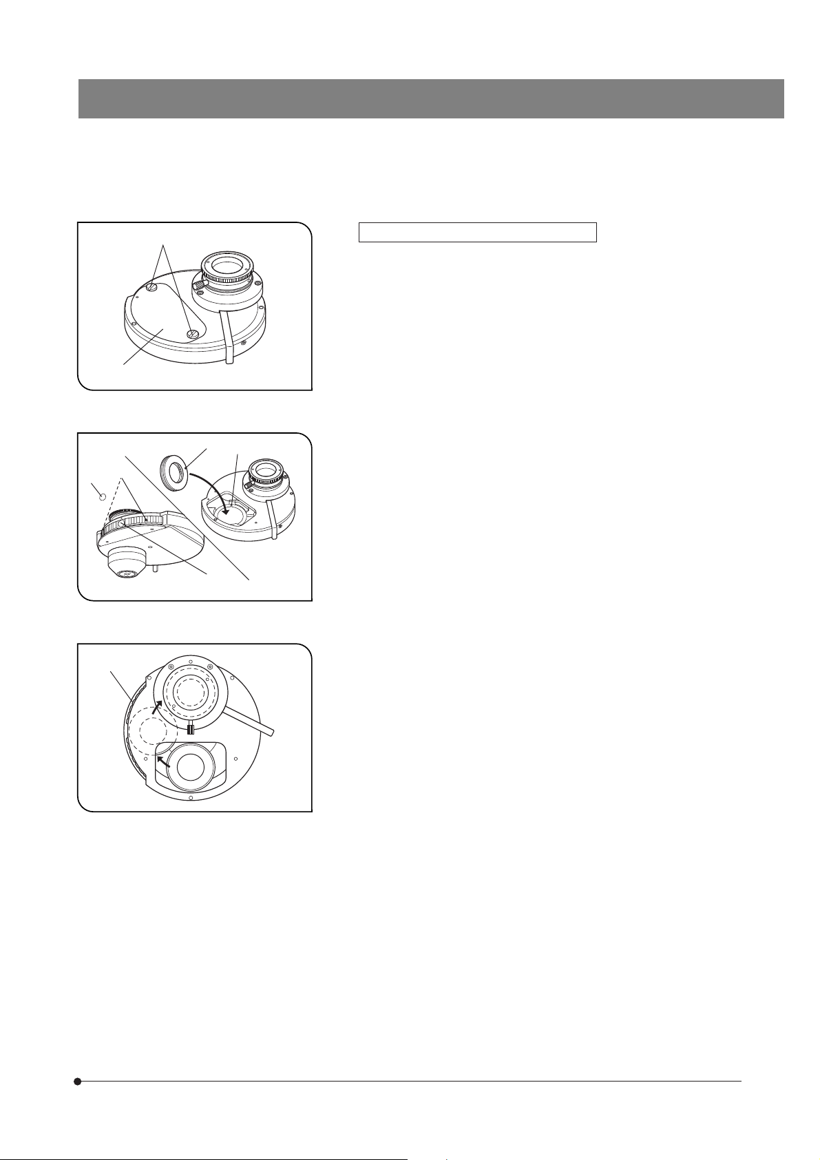
With the WI-DICD Condenser (Fig. 35)
}The WI-DICD should be attached after completing the polarizer position
as described in item
1. Remove the WI-DICD condenser from the microscope frame.
2. Remove the two clamping screws @ using the Allen screwdriver provided
with the microscope, then place the top of the condenser upside down.
3. When the DIC prism for use with the objective in use is a small DIC
prism, drop it in by aligning the positioning groove ² on the adapter
located on the inner side with the pin ³ of the prism.
When the DIC prism for use with the objective is a large DIC prism, remove the adapter and drop in the DIC prism.
}Retain the adapter for future possible use.
4. Tighten the clamping screws | with the knob provided with the condenser.
5. Attach the condenser on the microscope again.
With the U-UCD8
}Attach the DIC prism by referring to the instruction manual provided with
the U-UCD8.
5 .
³
Fig. 36
²
@
Adjusting the Polarizer Position
5
(except the U-UCD8)
#This adjustment is not necessary when the U-UCD8 is used. How-
ever, be sure to insert the WI-TP137 quarter-wave plate in a position
where the U-UCDTP530 one-wave plate for the U-UCD8 is otherwise
inserted.
}This adjustment is possible without removing the DIC prism (for revolving
nosepiece). However, it is not possible if a DIC prism for condenser is
engaged in the light path. Remove or disengage the DIC prism for condenser as described below.
· WI-DICD: Remove the DIC prism.
· WI-UCD: Rotate the turret to engage a position without DIC prism.
When the U-LH100IR Lamp Housing Is Used
Be sure to take the following measure to protect your eyes from
the IR rays.
}Insert the IR cut filter (light blue) provided with the microscope into
the filter slider @, then push it in to engage it. (See page 10.)
1. Remove the condenser from the microscope.
2. Remove an objective and engage the position without the objective in
the light path.
3. Engage the polarizer and analyzer in the light path (page 19) and turn the
transmitted light on.
(Figs. 36-38)
22
Page 27
4. Remove the eyepiece from the eyepiece sleeve, look into the sleeve, turn
the polarizer rotation dial ² so that the black interference stripe (Fig. 37)
is darkest, and tighten the clamping knob ³.
5. Engage an objective (as low-magnification as possible) in the light path,
attach the condenser and bring the specimen surface into focus.
²
Fig. 37
Fig. 38
@
Important
}With the WI-DICD, do not attach the DIC prism.
With the WI-UCD engage a position without DIC prism in the light path.
6. If the condenser has not been centered yet, center it (page 16).
}The interference stripe is not visible clearly if the field iris is focused insuf-
ficiently.
7. Turn the quarter-wave plate rotation ring @ so that the black interference
stripe seen at the center of the eyepiece sleeve’s field of view, then tighten
the clamping knob ². Ignore the short interference stripes in the surroundings in this adjustment.
Since this adjustment renders the field of view dark, observation cannot
be started unless the observation method described in the next item is
employed.
Now the adjustment is complete.
· Attach the eyepiece and objective again to the microscope frame.
· With the WI-DICD, remove it and mount the required DIC prism.
· When an IR cut filter is used, remove it and mount the required filter.
The interference stripe is less clearly visible when the
specimen is thick. In this case, it is recommended to
bring a scratch or like on the bottom of the petri dish to
facilitate the subsequent adjustment operation.
6 Observation Method
(Fig. 39)
²
Fig. 39
@
1. Engage the objective to be used in the light path.
2. When the WI-UCD or U-UCD8 condenser is used, engage the DIC prism
matching the objective in the light path by rotating the turret.
3. Place the specimen on the stage and bring the specimen into focus.
}The contrast may be improved by stopping down the aperture iris dia-
phragm to an optimum aperture.
4. Rotate the polarizer dial @ on the filter turret to obtain optimum contrast
for the specimen. Tighten the clamping knob ² if required.
Page 28

5-2 Reflected Light Fluorescence Observation
}Refer to the instruction manual of your reflected light fluorescence system.
Illuminator Shutter WI-RSH
}The shock during observation can be reduced by using this optional shutter in place of using the shutter built into the
BX-URA2 or BX-RFA reflected light illuminator.
Idle hole
Shutter position
To be used by inserting in the 6-position filter/polarizer
insertion slot of the reflected light illuminator.
5-3 Infrared Light (IR)/Differential Interference Contrast (DIC) Observation
}The IR rays (775 or 900 nm) transmit the specimen by about 4 or 5 times more than visible light (550 nm). Therefore, the IR
observation is suitable for observing deep areas of a thick brain slice or optic nerve specimen.
1 Introduction
1. Since the IR wavelength used is 775 to 900 nm, the TV camera in use should be sensitive in the wavelength used
(Example: C2741-79 CCD camera mfd. by Hamamatsu Photonics).
The IR light is harmful to your eyes. Avoid visual observation and use the TV monitor whenever possible. Should
visual observation be used, mount the IR cut filter (light blue) provided with the filter turret and engage the IR cut
filter in the light path. (See pages 10 and 22.)
2. To reduce the influence of heat on the specimen, stop down the field iris diaphragm of the BX51WI microscope as small
as possible. However, note also that the contrast may sometimes be improved by circumscribing the field iris image with
the field of view.
24
Page 29
3. To enable IR observation, the following modules should be replaced with those based on the IR specifications.
IR TV camera
TV adapter
Trinocular tune
U-TR30IR
U-ETR3
U-TR30-2
(Note)
Video contrast device such as
the ARGUS10, 20 by Hamamatsu
Photonics, monochrome video
monitor
BX51WI
Objective
· MPLN5X
· UMPlanFLN10XW/20XW
· LUMPlanFLN40XW/60XW
· LUMFLN60XW
· LUMPlanFl100XW
· XLUMPlanFl20XW
Usable with IR900nm.
Polarizer
32POIR
IR filter
32BP775 or 32IR900
Analyzer
WI-ANIR or
WI-ANTIR (+ U-KPA)
Lamp housing
U-LH100IR
Thermal reflection filter
45SCF
(Note) Notes for combination of the TV adapter, intermediate attachment and observation tube
When an observation tube other than the U-TR30IR is used, select the TV adapter by referring to combinations a) to c)
below.
# With IR observation, the combination with the U-PMTVC or U-DPT cannot manifest full performance.
a) Combination for observing a wide field (direct image 1X)
Direct image adapter
U-TV1X
Mount adapter
One of 3 models*
* The mount adapter should be one of: 1) U-CMAD3 mount adapter; 2) U-BMAD bayonet mount adapter; 3) U-SMAD Sony
camera mount adapter.
Note) When the contrast is enhanced rather excessively by an image processor, the central area of the monitored image
may be made bright and noticeable.
TV camera
(IR specification model)
b) Combination using C-mount adapter IR system (visible light to 1000 nm)
C-mount adapter IR system
U-TVCAC
U-PMTVC2XIR
C-mount TV camera
(IR specification model)
U-PMTVC4XIR
c) Combination using U-CA or U-ECA intermediate tube
One of these intermediate tubes can be used only in combination with the U-ETR3 or U-TR30IR trinocular tube. The TV
adapter used in this combination should be one of that used in a) or b).
25
Page 30

²
@
|
³
Fig. 40
Fig. 41
2 Attaching the IR Modules
Thermal Reflection Filter 45SCF
1. Remove the collector lens of the U-LH100IR lamp housing @ by loosening the 3 clamping screws ² with an Allen wrench (width across flats of
2.5 mm).
2. While positioning the 45SCF filter ³ so that the arrow on its frame points
in the opposite direction of the lamp housing, insert the filter in the lamp
housing, and clamp by tightening the ring spring | provided with the
filter.
3. Attach the collector lens to the original position.
(Figs. 40 & 41)
IR Filter 32BP775 or 32IR900
}Be sure to insert the 32BP775 or 32IR900 IR filter in the filter slider below
the filter turret. (For the mounting method, see page 10.)
#If the IR filter is inserted above the polarizer in the filter turret, the
polarizer will be burnt.
Other IR Modules
Also replace other required modules with the IR modules (see page 25).
26
Page 31
3 DIC Observation Using IR
Since IR light is harmful to your eyes, use the monitor observation whenever possible even in adjustments.
1. First, perform adjustments for DIC observation without using IR.
}Do not mount the IR filter and see Section 5-1, “Differential Interference Contrast Observation” on page 19.
BX51WI
Important
· Focus the field iris diaphragm image (page 16).
Be sure to perform this adjustment accurately because it determines the visual performance
using the IR light.
· With DIC observation using IR, do not stop down the aperture iris diaphragm lever @ but leave
the diaphragm open.
As the contrast can be enhanced using the video enhancement function of the CCD controller,
the diaphragm should be left open in this adjustment so that the optical performance can be
manifested fully.
@
2. Then engage the IR filter (32BP775 to 32IR900) in the light path by pushing in the filter slider.
3. While observing the monitor, perform DIC observation using IR.
a) Turn the condenser turret to select the DIC prism matching the objective to be used (except the WI-DICD).
b) Turn the revolving nosepiece to engage the objective to be used in the light path.
# Penetration of air bubbles inside the front lens of objective will deteriorate the view. To prevent this by removing
the bubbles, turn the revolving nosepiece slightly to move the immersed objective to the left and right for a few
times.
c) Bring the specimen into focus by moving the objective up and down using the coarse and fine adjustment knobs.
4. Turning the 32POIR polarizer varies the density of the background. Set the polarizer to obtain optimum contrast for the
specimen.
27
Page 32

5-4 Macro Reflected Light Fluorescence Observation
}The macro reflected light fluorescence observation makes possible bright, low-magnification fluorescence observation by
combining low-magnification fluorescence mirror units and fluorescence objective.
1 Introduction
1. For the low-magnification fluorescence observation, use a low-magnification fluorescence mirror units.
The increased observation beam diameter of the fluorescence mirror units brightens the fluorescence by about 25%.
However, due to the large size of the fluorescence mirror units, they can be mounted only in every other position when the
BX-URA2 or BX-RFA reflected fluorescence illuminator is used (a total of 3 units can be mounted on each illuminator).
2. When performing transmitted light brightfield observation using a low-magnification fluorescence objective (2X or 4X),
also use the U-SC3 or U-UCD8 swinging condenser. If other condenser is combined, it will not be possible to illuminate
the entire field of view.
3. During low-magnification fluorescence observation, objective switching or stage movement, be careful so that the UIS2
(UIS) objective does not interfere with the specimen or culture container.
4. The low-magnification fluorescence objectives have been designed to manifest performances with no-covered dry specimens to specimens located 5 mm below water surface level.
As a result, with water immersed specimens, the focused positions of these objectives are different from UIS2 (UIS)
objectives.
5. To enable macro reflected light fluorescence observation, the following modules should be replaced.
Low-magnification fluorescence
mirror units
U-MGFP/XL
U-MGFPA/XL
U-MF/XL
Sliding revolving nosepiece
U-SLRE
Low-magnification fluorescence objective
XLFluor2X/340
XLFluor4X/340
Water immersion cap for XL objective
XL-CAP
UIS2 objective
UMPlanFLN-W series
LUMPlanFLN-W series
LUMFLN60XW
UPlanSApo10X to 40X
UPlanFLN10X to 40X only
Condenser
U-SC3
U-UCD8
28
Page 33
BX51WI
…
@
³
ƒ
²
Fig. 42
Fig. 43
|
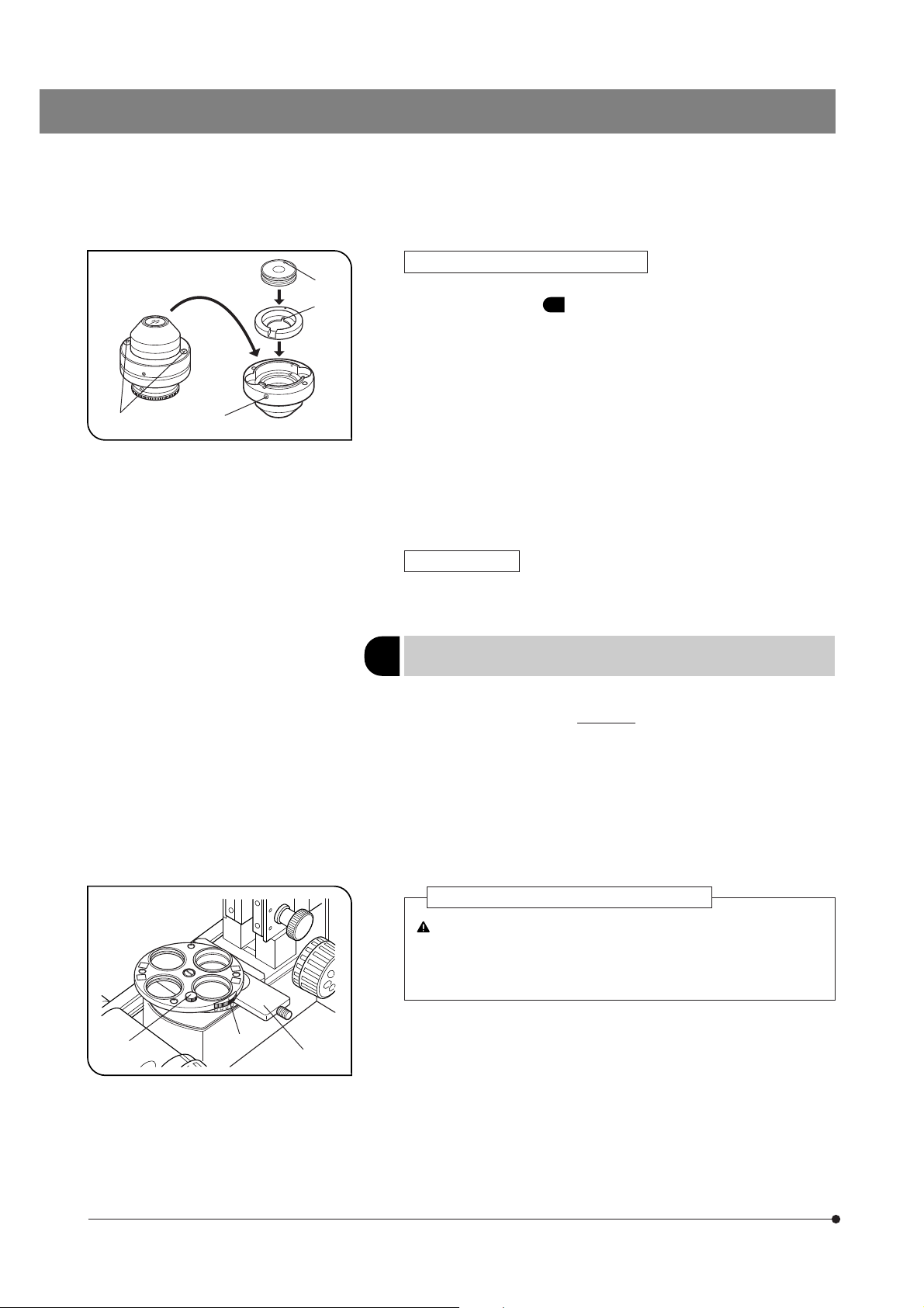
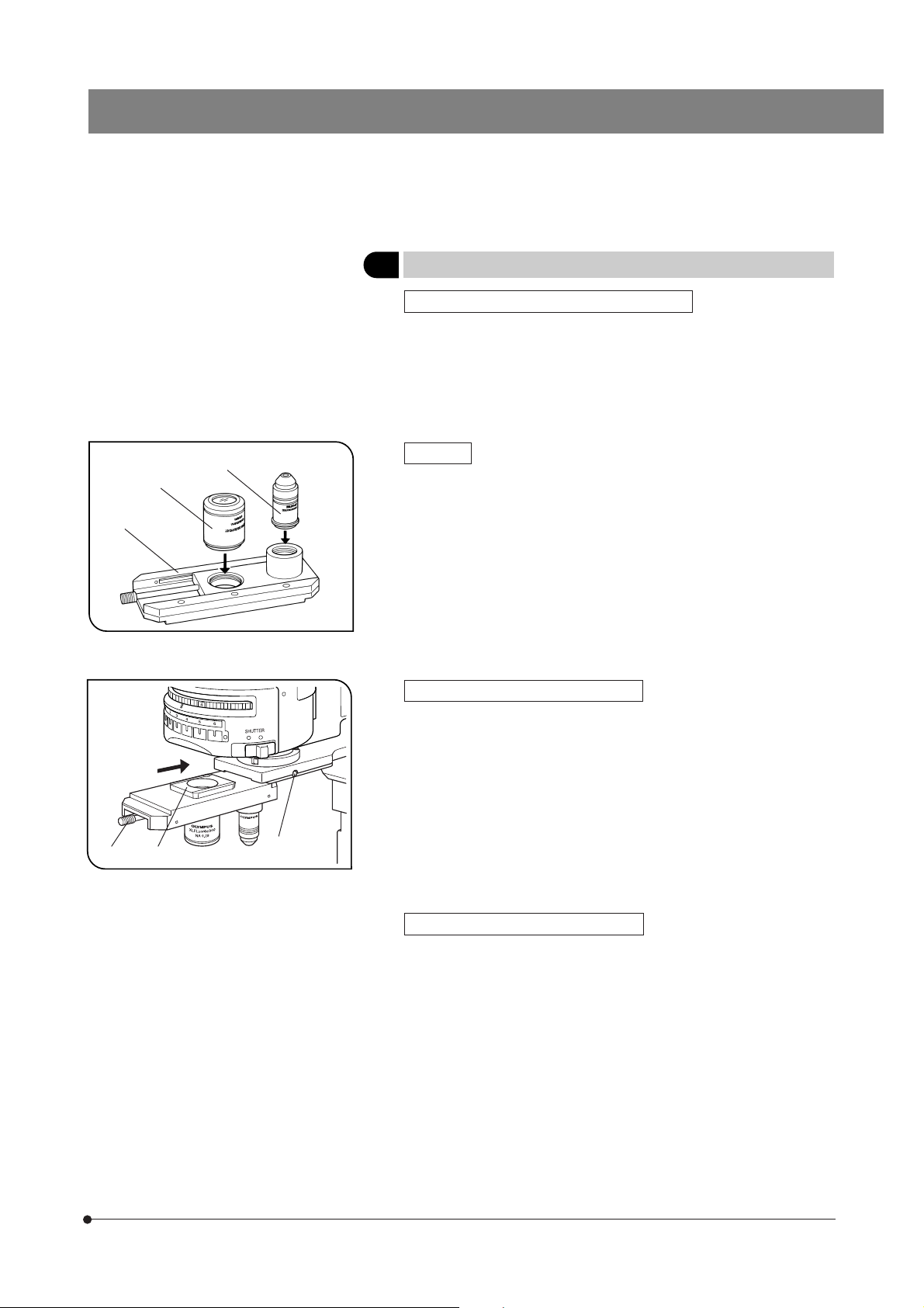
2 Attaching the Modules
Low-Magnification Fluorescence Mirror Units
}Select the suitable mirror units for purpose of observation by referring to
page 30.
}If you want to fabricate optional mirror units, see page 30.
· Mount the mirror units as indicated in the instruction manual of your
reflected light fluorescence system.
Note that mirror units can be mounted only in every other positions.
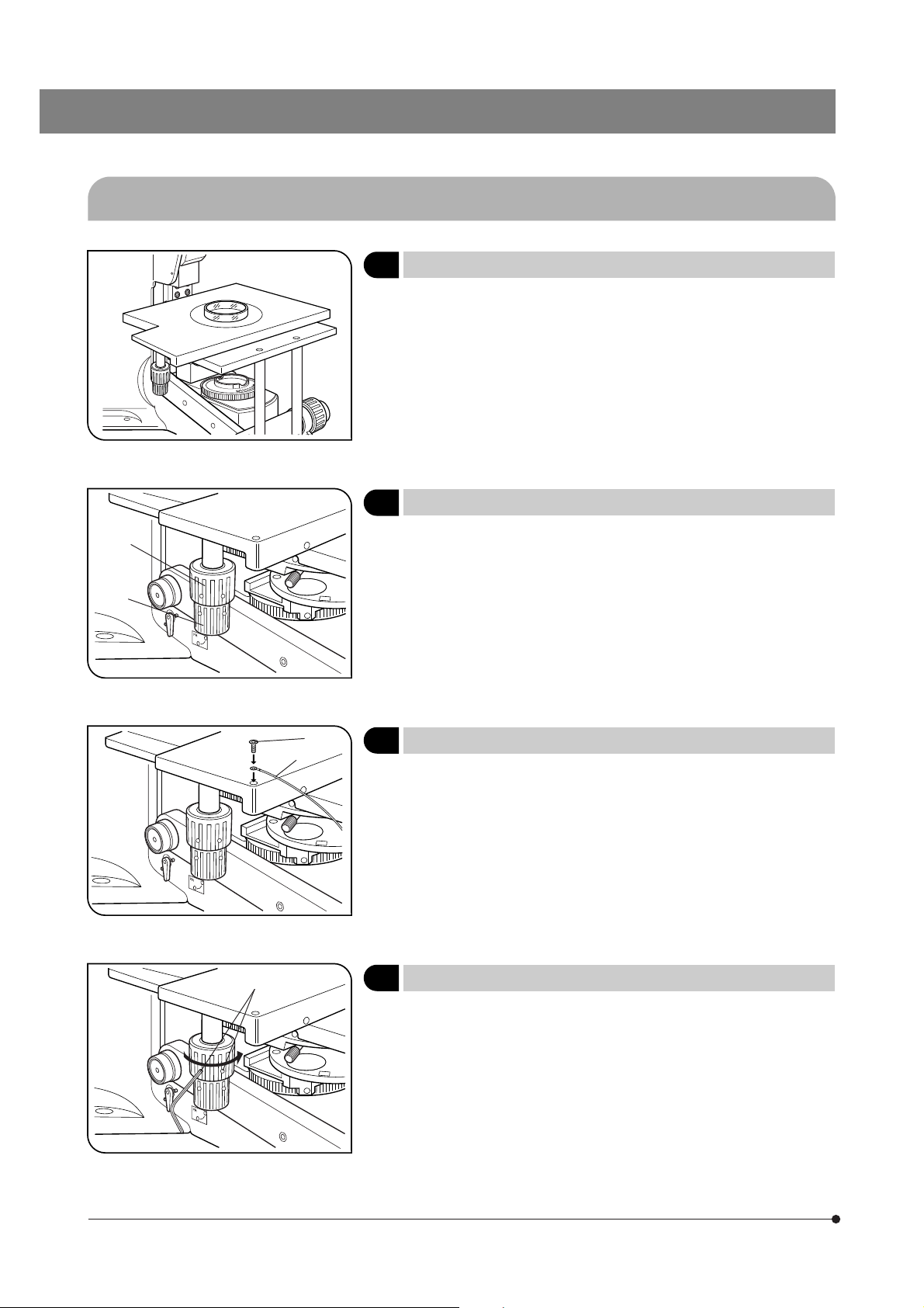
Objective
1. Screw a UIS2 objective ² into the position on the deeper side of the U-SLRE
sliding revolving nosepiece @.
2. Screw a XLFluor2X/340 or XLFluor4X/340 low-magnification fluorescence
objective ³ into the position on the shallower side of the U-SLRE.
Sliding Revolving Nosepiece U-SLRE
1. Raise the revolving nosepiece mount fully by rotating the coarse adjustment knob of the microscope frame.
2. Loosen the revolving nosepiece mount screw | on the microscope frame
using the Allen screwdriver provided with it.
3. Align the mount dovetail ƒ of the sliding revolving nosepiece with the
revolving nosepiece mount dovetail and gently slide the sliding revolving
nosepiece all the way in from the front as shown in the figure.
4. Clamp the revolving nosepiece by tightening the revolving nosepiece
mount screw |.
(Figs. 42 & 43)
Swinging Condenser U-SC3/U-UCD8
# Attach the U-SC3 with the top lens swung out.
The condenser top lens should be swung out when using the 2X or
4X objective.
29
Page 34
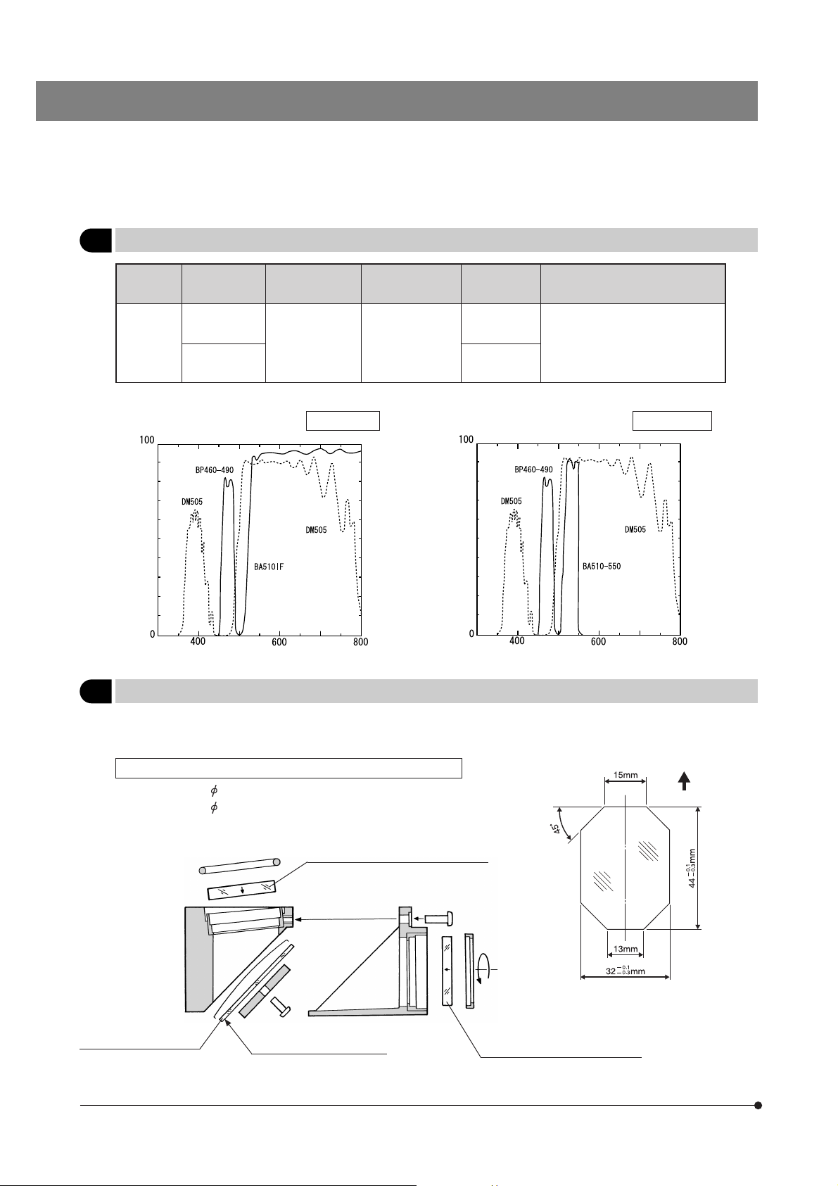
3 Filter Characteristics of Fluorescence Mirror Units
Excitation
Method
IB
1. IB excitation (wide bandwidth) U-MGFP/XL 2. IB excitation (wide bandwidth) U-MGFPA/XL
Transmittance (%)
Mirror Unit Dichroic Mirror Excitation Filter Barrier Filter Application
U-MGFP/XL
DM505 BP460-490
U-MGFPA/XL
Wavelength (nm) Wavelength (nm)
BA510IF
BA510-550
Transmittance (%)
For EGFP, S65T, RSGFP.
(U-MGFPA/XL is for fluorochrome
separation.)
4 Fabricating Optional Mirror Unit
}An optional mirror unit can be fabricated by attaching the custom-order barrier filter, excitation filter and dichroic mirror to
the U-MF/XL.
Dimension Conditions of Optical Components of Mirror Unit
· Barrier filter: 32
· Excitation filter: 25
· Dichroic mirror: See figure on the right.
Dichroic mirror
(made to custom order)
# When replacing the dichroic mirror, take special care not to stain it by leaving fingerprints, etc.
-0.1/-0.2
mm, max. thickness 4 mm
-0.1/-0.2
mm, max. thickness 6 mm
Barrier filter (made to custom order)
Interference mirror surface
Thickness: 1.5 ±0.05 mm
Excitation filter
(made to custom order or
ommercially marketed product)
UP
30
Page 35
BX51WI
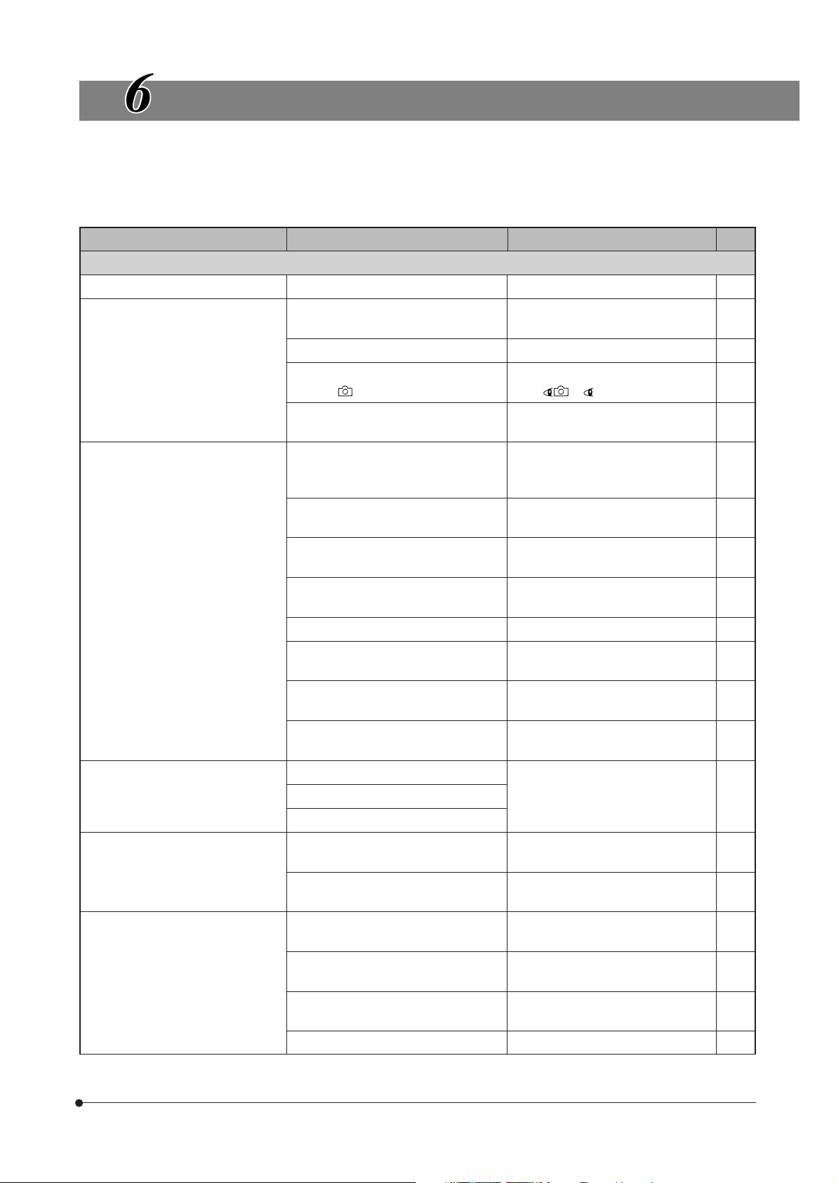
TROUBLESHOOTING GUIDE
Under certain conditions, performance of the microscope may be adversely affected by factors other than defects. If problems
occur, please review the following list and take remedial action as needed.
If you cannot solve the problem after checking the entire list, please contact your local Olympus representative for assistance.
Problem
1. Optical System
a) The bulb does not light. The bulb is burned out. Replace the bulb. 41
b) The bulb lights but the field of view
is dark.
c) Field of view is obscured or not
evenly illuminated.
The aperture or field iris diaphragm is
opened in sufficiently.
The condenser is in too low a position. Adjust the condenser height. 16
The light path selector knob of is set to
position .
The voltage selector knob is set to a low
voltage position.
The light path selector knob is in an intermediate position.
The revolving nosepiece is not in a click
position.
The revolving nosepiece is installed incorrectly.
The filter turret or filter slider is incorrectly
engaged in the light path.
The condenser is not centered. Adjust the centering. 16
Cause Remedy Page
Open the aperture and field iris diaphragms.
Set the light path selector knob to position or .
Set it to the high voltage position.
Set the light path selector knob to a
click position according to the purpose.
Set it in a click position.
Secure it by pushing in the sliding
dovetail all the way until the stopper.
Engage them correctly in the light path.
16
15
10
15
13
38
10
d) Dirt or dust is visible in the field of
view.
e) Image glares.
f ) Visibility of observed image is poor.
· Image is not sharp.
· Contrast is poor.
· Details are poorly visible.
The frost switching lever is set to an intermediate position or OUT.
The field iris diaphragm is closed too
much.
The lamp bulb is not installed correctly. Push the halogen bulb terminals all
Dirt/dust on eyepiece. Clean thoroughly.
Dirt/dust on condenser top lens.
Dirt/dust on specimen.
The condenser is set to too low a position.
The aperture iris diaphragm is closed too
much.
The objective in use is not designed for
UIS2 (UIS) series.
The revolving nosepiece is installed incorrectly.
The objective is engaged incorrectly in
the light path.
Air in the objective front lens. Remove the air. –
Engage the frost filter correctly in the
light path.
Open it sufficiently.
the way into stop position.
Adjust the condenser height.
Open it sufficiently.
Replace with a specified objective for
UIS2 (UIS) series.
Secure it by pushing in the sliding
dovetail all the way until the stopper.
Make sure that revolving nosepiece
clicks into place correctly.
11
16
41
2
16
17
35
38
13
31
Page 36

Problem
f ) Visibility of observed image is poor.
· Image is not sharp.
· Contrast is poor.
· Details are poorly visible.
g) One side of image is blurred. The revolving nosepiece is installed in-
The specimen such as a brain slice is
fixed poorly.
Bubbles attached to the objective front
lens.
Too small quantity of solution in the petri
dish.
The petri dish is tilted. Place the petri dish correctly on the
Dirt/dust on the objective front lens. Clean it thoroughly using neutral de-
Dust/dirt on the condenser.
correctly.
The objective is engaged incorrectly in
the light path.
The objective is placed incorrectly (may
be loose) in the revolving nosepiece
position.
The stage center plate is tilted. Correct the tilt. –
Cause Remedy Page
Fix it correctly.
Remove the bubbles.
Supply sufficient solution in the petri
dish.
stage.
tergent.
Clean it thoroughly. 2
Secure it by pushing in the sliding
dovetail all the way until the stopper.
Make sure that revolving nosepiece
clicks into place correctly.
Insert the objective all the way into the
revolving nosepiece position until it is
stopped.
–
–
–
12
–
38
13
–
h) Image appears to waver. The revolving nosepiece is installed in-
correctly.
The objective is engaged incorrectly in
the light path.
The objective is placed incorrectly (may
be loose) in the revolving nosepiece
position.
The condenser is centered incorrectly. Center it correctly. 16
i ) The field of view becomes brighter
only slightly although the voltage is
increased.
2. Electrical System
a) The bulb intermittently lights and
goes out.
b) The lamp bulb burns out soon after
lighting.
c) The brightness cannot be varied
with the light intensity control.
The condenser is centered incorrectly. Center it correctly. 16
The condenser is in too low a position. Adjust the condenser height. 16
The bulb is nearly burnt out. Replace the bulb. 41
A cord or connector is not properly connected.
The bulb in use is not the specified lamp. Replace with a standard bulb.
No lamp bulb is installed. Attach a lamp bulb. 41
The lamp bulb is burnt out. Replace the lamp bulb. 41
The lamp housing output connector is
unplugged.
Secure it by pushing in the sliding
dovetail all the way until the stopper.
Make sure that revolving nosepiece
clicks into place correctly.
Insert the objective all the way into the
revolving nosepiece position until it is
stopped.
Connect cords and plugs securely.
Plug the lamp housing output connector.
38
13
–
–
41
–
32
Page 37

BX51WI
Problem
3. Coarse/Fine Adjustment Knobs
a) Coarse adjustment knob is too
heavy to rotate.
b) The objective cannot be lowered
enough.
c) Objective confocality is not
achieved with the WI-SRE3.
4. Observation Tube
a) The field of view of one eye does
not match that of the other.
5. Stage
Cause Remedy Page
The rotation tension adjustment ring is
secured tightly.
The pre-focusing lever is locked. Release the pre-focusing lever. 11
The pre-focusing lever is functioning. Release the pre-focusing lever.
Adjustment is not correct. Adjust correctly.
The interpupillary distance is incorrect. Adjust interpupillary distance. 14
Incorrect diopter adjustment. Adjust diopter. 14
Different eyepieces are used on the left
and right.
You are not accustomed to parallel optical axis.
Fully loosen the ring by turning it counterclockwise.
Change one eyepiece to match the
other so that both sides are of the
same type.
When looking into eyepieces, do not
stare at image from the beginning but
see the overall field of view. It is sometimes recommended to turn your eyes
away from eyepieces, look far off and
look into eyepieces again.
11
11
38,39
–
–
a) Stage travel in the horizontal (X-axis)
direction stops in the middle.
b)The X-axis and/or Y-axis stage
knobs are too light or too heavy to
rotate.
The specimen is set incorrectly. Place the specimen correctly.
The X-axis and/or Y-axis rotation tension
is not adjusted properly.
Adjust the knobs to optimum tension.
12
12
33
Page 38

SPECIFICATIONS
Item Specification
1. Optical system UIS2 (UIS) (Universal Infinity System) optical system (Infinity correction)
2. Illumination system Transmitted Kohler illumination built in (FN 22)
12 V, 100 W long-life halogen bulb (pre-centered)
Average life time: Approximately 2000 hr. when used as directed.
Light intensity voltage range: 2.5 12.6 V DC (continuously variable), 8.4 A max.
Power consumption: 140 W
3. Focusing system Revolving nosepiece height movement by roller guide (rack & pinion)
Stroke per rotation: 0.1 mm (fine), 15 mm (coarse)
Full stroke range: 25 mm
Pre-focusing lever
Coarse adjustment knob: Tension adjustment possible
4. Revolving nosepiece Model
Attachable modules
WI-SRE3
Swinging Revolving
Nosepiece
DIC prisms mountable DIC prisms mountable
U-SLRE
Sliding Revolving
Nosepiece
WI-SNPXLU2
Single-Position
Revolving Nosepiece
5. Observation tube Model U-TR30-2
Widefield Trinocular
Field number 22
Tube tilting 30° 25°
Interpupillary
distance adjustment
Light path
selection
6. Stage Model
X/Y movement
mechanism
7. Long-WD condenser Model
N.A. 0.8
Working distance
Aperture iris Variable aperture iris diaphragm
Turret 4-position
3-step switching: @Binocular 100%
²Binocular 80%
TV/photo 20%
³TV/photo 100%
X-axis/Y-axis knob tension adjustable
Movement range: 50 mm (X-axis) x 45 mm (Y-axis)
WI-UCD
Universal Condenser
Widefield, Upright-Image Trinocular
50 mm to 76 mm
2-step switching: @ Binocular 100%
IX-SVL2
Stage with Bottom-Side Knobs
WI-DICD
DIC Condenser
5.7 mm
U-ETR3
²TV/photo 100%
WI-OBCD
Oblique Condenser
34
DIC prisms
Other Quarter-wave plate built in
8. Operating environment · Indoor use
· Altitude: Max. 2000 m
· Ambient temperature: 10° to 40°C (50° to 104°F)
· Maximum relative humidity: 80% for temperatures up to 31°C (88°F), decreasing linearly
through 70% at 34°C (93°F), 60% at 37°C (99°F), to 50% relative humidity at 40°C (104°F)
· Supply voltage fluctuations: ±10%
· Pollution degree: 2 (in accordance with IEC60664)
· Installation (overvoltage) category: II (in accordance with IEC60664)
Max. 4 prisms can be mounted.
Only 1 prism can be mounted.
Variable oblique iris built in
Page 39
BX51WI
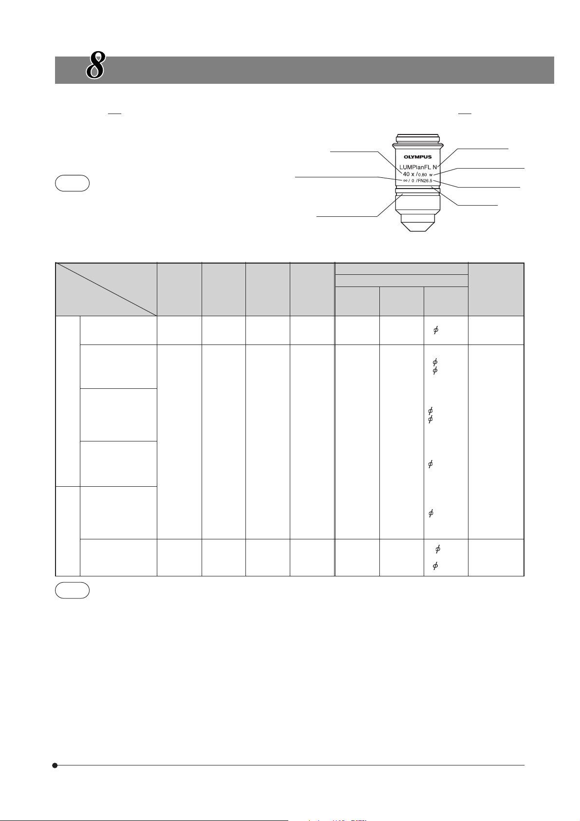
OPTICAL CHARACTERISTICS
UIS series objectives not listed here can also be combined with this microscope.
The following table shows the optical characteristics of combinations of eyepieces and objectives. The figure on the right shows
the performance data engraved on the objectives.
Magnification
Objective type
NOTE
Refer to the latest catalogue or consult your local Olympus
representative for the updated information on the eyepieces
and objectives that can be combined with this microscope.
Optical
Objective
MPLN
UIS2
Plan Achromat
series
(FN 22)
UMPlanFLN-W
Water Immersion
Universal Plan SemiApochromat
(FN 26.5)
LUMPlanFLN-W
Long-WD Water
Immersion Universal
Plan SemiApochromat
(FN 26.5)
LUMFLN-W
Long-WD Water
Immersion Universal
Semi-Apochromat
(FN 26.5)
LUMPlanFl-W
UIS
Long-WD Water
series
Immersion Universal
Plan SemiApochromat
(FN 26.5)
XLFluor
Low-Power
Fluorescence
(FN 22)
character
Power
5X 0.1 20.0 3.36 50X 98 4.4
10XW 0.30 3.50 1.10 100X 20 2.2
20XW 0.50 3.50 0.67 200X 6.1 1.1
40XW* 0.80 3.30 0.42 400X 2.0 0.55
60XW* 1.00 2.00 0.34 600X 1.3 0.37
60XW* 1.10 1.50 0.31 600X 0.7 0.37
100XW* 1.00 1.50 0.34 1000X 0.83 0.22
2X/340 0.14 20.0 2.40 20X 132 11
4X/340 0.28 28.4 1..20 40X 33.0 5.5
N.A.
W.D.
(mm)
Mechanical tube length
Water immersion
indicator (white)
Resolution
(μm)
Total
Power
Eyepiece
WHN10X (FN22)
Focal
Depth
(μm)
Number of aperture
FN (Field number)
Color band
Actual
Field
Water immersion
impossible
*Usable with IR
Correction
collar
Water immersion
impossible
Water immersion
impossible
Remark
900 nm.
NOTE
After using a water immersed objective, be sure to clean the extremity using neutral detergent. If the extremity is
left without cleaning, contamination remains and the objective performance will deteriorate.
35
Page 40

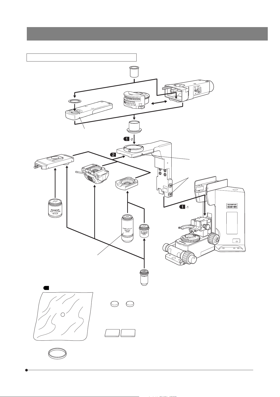
ASSEMBLY
9-1 Assembly Diagram
The diagram below shows the sequence of assembly of the modules. The numbers indicate the order of assembly.
The module numbers shown in the following diagram are merely the typical examples. For the modules with which the
module numbers are not given, please consult your Olympus representative or the latest catalogues.
# When assembling the microscope, make sure that all parts are free of dust and dirt, and avoid scratching any parts
or touching glass surfaces.
Assembly steps enclosed in will be detailed on the subsequent pages.
}All assembly operations are possible by using the Allen screwdriver ( ) provided with the microscope frame.
However, the reflected light illuminator or transmitted light arm should be attached using the Allen wrench provided with the
illuminator or arm to tighten the clamping screws. (To assure the performance, please have your dealer assemble the
illuminator or arm.)
The filter turret and cross stage are to be cleaned respectively using the special tools provided with them.
(Note) For the detailed assembly procedures of the reflected light fluorescence system and the TH4 power supply unit, refer to
their instruction manuals.
Eyepieces
WHN10X (FN 22)
35WHN10X (FN 22)
Revolving arm
Revolving
nosepiece
Objectives
(See next page.)
Intermediate
attachment
U-ECA
U-FWO
U-KPA, etc.
Trinocular tube
U-TR30-2 (FN 22)
U-ETR3 (FN 22)
Transmitted light arm
BX-ARM
Reflected light fluorescence illuminator
BX-URA2
BX-RFA
Power supply unit
U-RFL-T
Reflected light mercury bulb
lamp housing
U-LH100HG
U-LH100HGAPO
Cross stage
IX-SVL2
Fixed stage
adapter
WI-FSH
Stage center plate
Condenser
WI-UCD
WI-DICD
WI-OBCD
U-UCD8
U-SC3
Microscope frame
BX51WIF
Lamp socket clamping screw
Condenser clamping knob
Filter turret
Filter frame
reinforcing ring
Power supply unit
TH4
Halogen lamp housing
U-LH100-3
U-LH100IR
Extension cord
U-RMT
Hand switch
TH4-HS
36
Page 41
Revolving Arm, Revolving Nosepiece, Objectives
BX51WI
Light shielding tube
Light shielding tube
(transmitted light arm adapter)
Transmitted light arm
BX-ARM
Sliding revolving nosepiece
U-SLRE
Objective
XLFluor2X/340
XLFluor4X/340
The revolving nosepiece
clamping screw is not used.
Swinging
revolving
nosepiece
WI-SRE3
Light shielding tube
XLU single-position
revolving nosepiece
WI-SNPXLU2
RMS adapter
WI-RMSAD
Reflected light fluorescence
illuminator
BX-URA2
BX-RFA
Revolving arm
WI-NPA
Revolving nosepiece
clamping screw
Clamping screws
Objective
XLUMPlanFl20XW
UIS2 (UIS) objective
5 Waterproof cover (x 3) : Antimicrobial polyethylene
Magnets
Magnet support plates
(with double-side adhesive tape)
Clamping band
Microscope frame
BX51WIF
37
Page 42
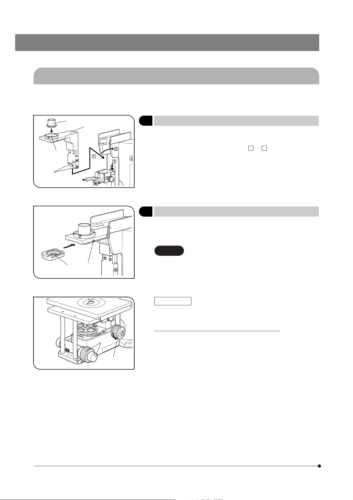
9-2 Detailed Assembly Procedures
}When performing observation on a desktop, attach the provided rubber feet (x 4) to the front (x 2) and rear (x 2) parts on the
bottom of the base.
²
|
³
²
@
Fig. 44
@
Fig. 45
1 Attaching the Revolving Arm
1. Loosen the 2 clamping screws ² of the revolving arm @ using an Allen
screwdriver and fit the arm into the mount dovetail on the microscope
frame along the direction of arrow from to .
2. Push the revolving arm all the way until it is stopped, then tighten the
clamping screws.
3. Screw in the light shielding tube ³ into the retaining screw |.
1 3
2 Attaching the Revolving Nosepiece
}The attaching procedure is common for the U-SLRE, WI-SRE3 and WI-
SNPXLU2 revolving nosepieces, except that the WI-SNPXLU2 should be
inserted so that the round end comes on the front.
CAUTION
1. Loosen the revolving nosepiece clamping screw @ using an Allen screwdriver, and slide in the revolving nosepiece ² along the mount dovetail.
2. Push the revolving nosepiece all the way in and tighten the clamping
screw.
In DIC observation using the WI-SRE3 or WI-SNPXLU2
revolving nosepiece, attach the DIC prisms before attaching the revolving nosepiece (see page 20).
(Fig. 44)
(Fig. 45)
38
Fig. 46
@
²
WI-SRE3 Only
}When the microscope has been assembled, the confocality adjustment
and centering of the two objectives can be performed.
Adjusting the Confocality of Objective (Figs. 46 & 47)
}To maintain the accurate focusing even after the objective is switched,
the height of the objective with the higher focal point is corrected by
attaching a washer.
Nine washers with three kinds of thickness (10, 30 and 50 μm), three per
kind, are provided with the microscope.
1. Engage the objective on the front side in the light path. Use the coarse/
fine adjustment knobs on the front side to adjust focusing.
}Accurate focus cannot be achieved if the coarse/fine adjustment knobs
on the back side are used.
2. To find the confocality difference, read the scale indication of the fine
adjustment dial ² (1 scale graduation: 1 μm).
Page 43
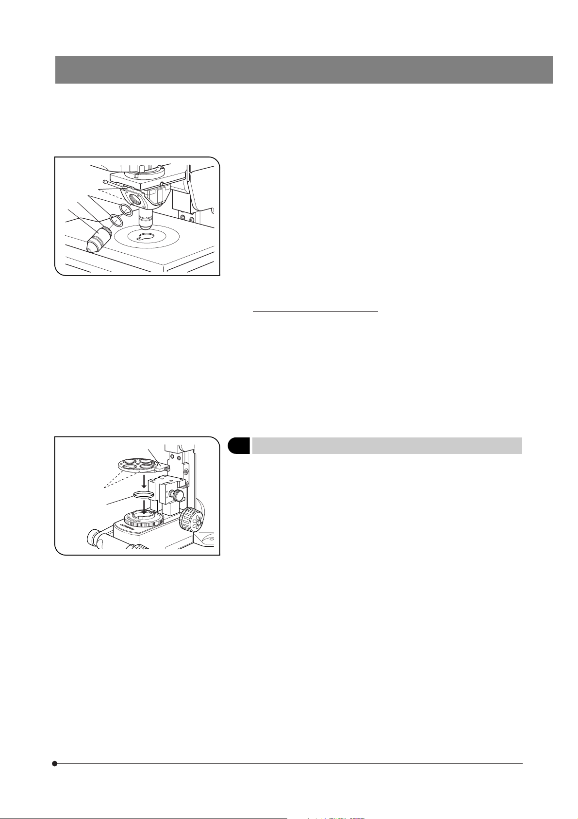
³
|
ƒ
…
Fig. 47
BX51WI
3. Engage the objective on the back side in the light path.
Adjust focusing, read the scale indication of the fine adjustment knob
and obtain the difference from the value read in step 2 above.
4. The objective to use the washer is determined by the rotation direction of
the fine adjustment dial ². (Fig. 46)
· Direction of the arrow: Objective on the back side.
· Opposite direction to the arrow: Objective on the front side.
5. Remove the objective ³, fit the washer ƒ with the required thickness on
the screw |, then attach the objective again.
6. Switch the objective and confirm that confocality is implemented.
# The confocality adjustment may sometimes be unable to implement
perfect confocality.
Centering the Objective (Fig. 47)
}The centering mechanism is provided only for the objective on the front
side.
1. Adjust focusing using the objective on the back side, then move the
target region in the specimen on the center of the field.
2. Switch the objective to that on the front side.
3. Insert the centering knobs into the threaded holes … and turn them to
move the target in the objective on the center.
}After completing centering, store the centering knobs in the accommo-
dation position on the front side of the microscope (page 4) so as not to
lose them.
³
²
@
Fig. 48
3 Attaching the Filter Turret
}When a bridge stage or a stage with similar design is used, the filter slider
@ can be attached so that it faces toward the front of the microscope.
1. Drop in the filter frame reinforcing ring ² into the filter holder on the
microscope base.
2. Loosen the 3 filter turret clamping screws ³ using the provided Allen
wrench.
3. Fit the filter turret on the filter holder and tighten the clamping screws ³.
4. For the insertion of the polarizer and filters, see page 10.
(Fig. 48)
39
Page 44
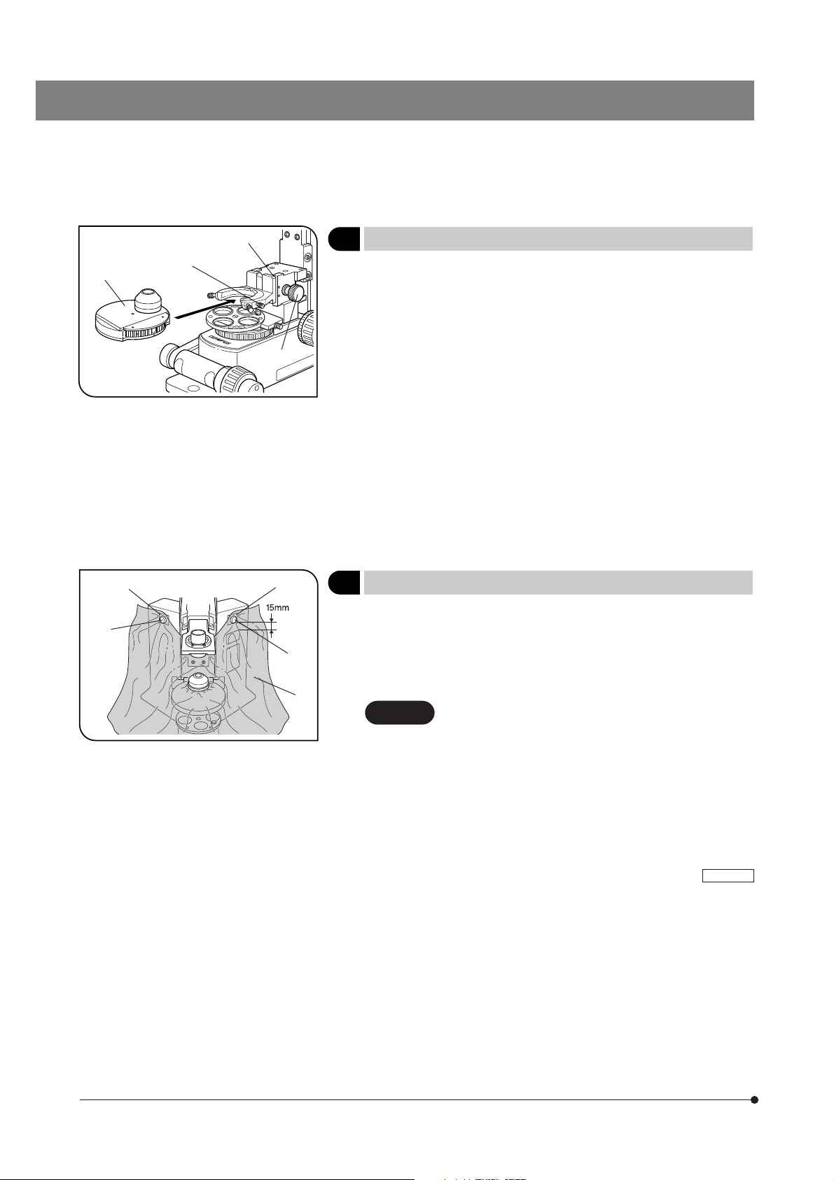
|
³
Fig. 49
@
²
4 Attaching the Condenser
#When attaching a condenser other than the WI-UCD, remove the
upper limit stopper screw @ of the condenser holder with an Allen
screwdriver.
}In DIC observation, attach the DIC prism (for condenser) before attaching
the condenser onto the microscope frame (page 20). However, with the
WI-DICD condenser, the DIC prism should be attached after adjusting the
polarizer position.
1. Rotate the condenser height adjustment knob ² to raise the condenser
holder to an optimum height.
2. Fully loosen the condenser clamping knob ³.
3. Slide in the condenser | from the front along the mount dovetail all the
way until it is stopped.
# When the microscope frame has a positioning pin on the rear position
of the condenser, align the condenser with the groove on the condenser holder.
4. Tighten the condenser clamping knob and lower the condenser holder
to the lowest limit position.
(Fig. 49)
³
²
Fig. 50
²
³
@
5 Attaching the Waterproof Cover
}Attach the waterproof cover onto the condenser if required.
The waterproof cover is applicable only to the WI-UCD, WI-DICD and WIOBCD condensers.
1. Fit the hole of the waterproof cover @ in the extremity of the condenser
and clamp with the clamping band.
CAUTION
2. To fix the skirt of the waterproof cover, attach the double-side adhesive
tape of the magnetic support plates ² to both sides of the microscope
frame.
}The magnetic support plates ² are most effective when they are at-
tached symmetrically at positions by about 15 mm above the
indications.
3. Fix the waterproof cover using magnets ³.
}When the cross stage is used, the stage mounting screw holes (x 4 on
the front and rear) are hidden by the waterproof cover. However, this does
not pose problem because the screws can later be attached by passing
through the waterproof cover.
In DIC observation, the condenser has to be removed
and attached during adjustments. Therefore, in this case,
do not attach the clamping band but just fit the hole of
the waterproof cover in the extremity of the condenser
and attach the clamping band after completing the adjustments.
(Fig. 50)
BX51WI
40
Page 45
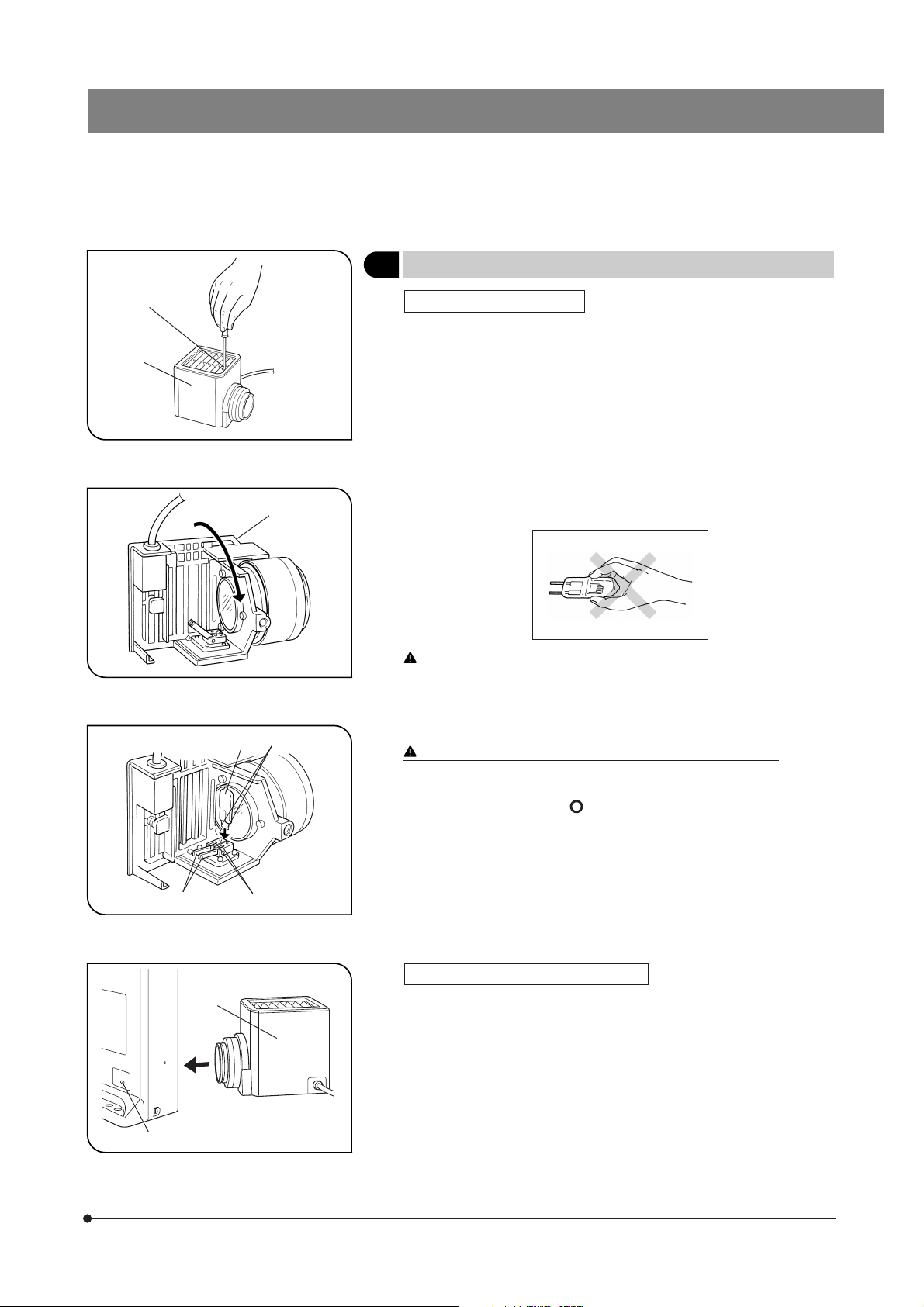
BX51WI
²
@
Fig. 51
Fig. 52
ƒ
³
…
6 Attaching the Halogen Lamp Housing
Attaching the Halogen Bulb
}The applicable lamp bulb model is the 12V100WHAL-L (PHILIPS 7724) or
the 12V50WHAL-L (LIFE JC).
1. Fully loosen the clamping screw @ at the top of the lamp housing using
the Allen screwdriver provided with the microscope frame.
2. Remove the lamp housing ² by lifting it up.
3. Tilt the bulb socket ³ by 90° in the direction of the arrow.
4. While pushing down the bulb clamping lever | down, hold the halogen
bulb ƒ with gloves or a piece of gauze, insert the bulb pins … straight
and fully into the sections † on the lamp socket.
Then return the lamp clamping lever gently back to the original position
to clamp the bulb.
To prevent reduced bulb life or cracking, do not touch the bulb with
bare hands. If fingerprints are accidentally left on the bulb, wipe the
bulb with a soft cloth.
5. Fit the lamp housing from up and tighten the clamping screw @ by
applying downward pressure. (Fig. 51)
Caution for Bulb Replacement During or Right after Use
The bulb, lamp housing and areas near these will be extremely hot
during and right after use.
Set the main switch to “ ” (OFF), disconnect the power cord from
the wall outlet, then allow the old bulb and lamp socket to cool before replacing the bulb with a new of the designated type.
(Figs. 51-54)
@
|
Fig. 53
²
Fig. 54
†
Attaching the Halogen Lamp Housing
1. Loosen the bulb socket clamping screw @ using the Allen screwdriver.
2. Push in the halogen lamp housing ² with bulb and tighten the clamping
screw @.
41
Page 46
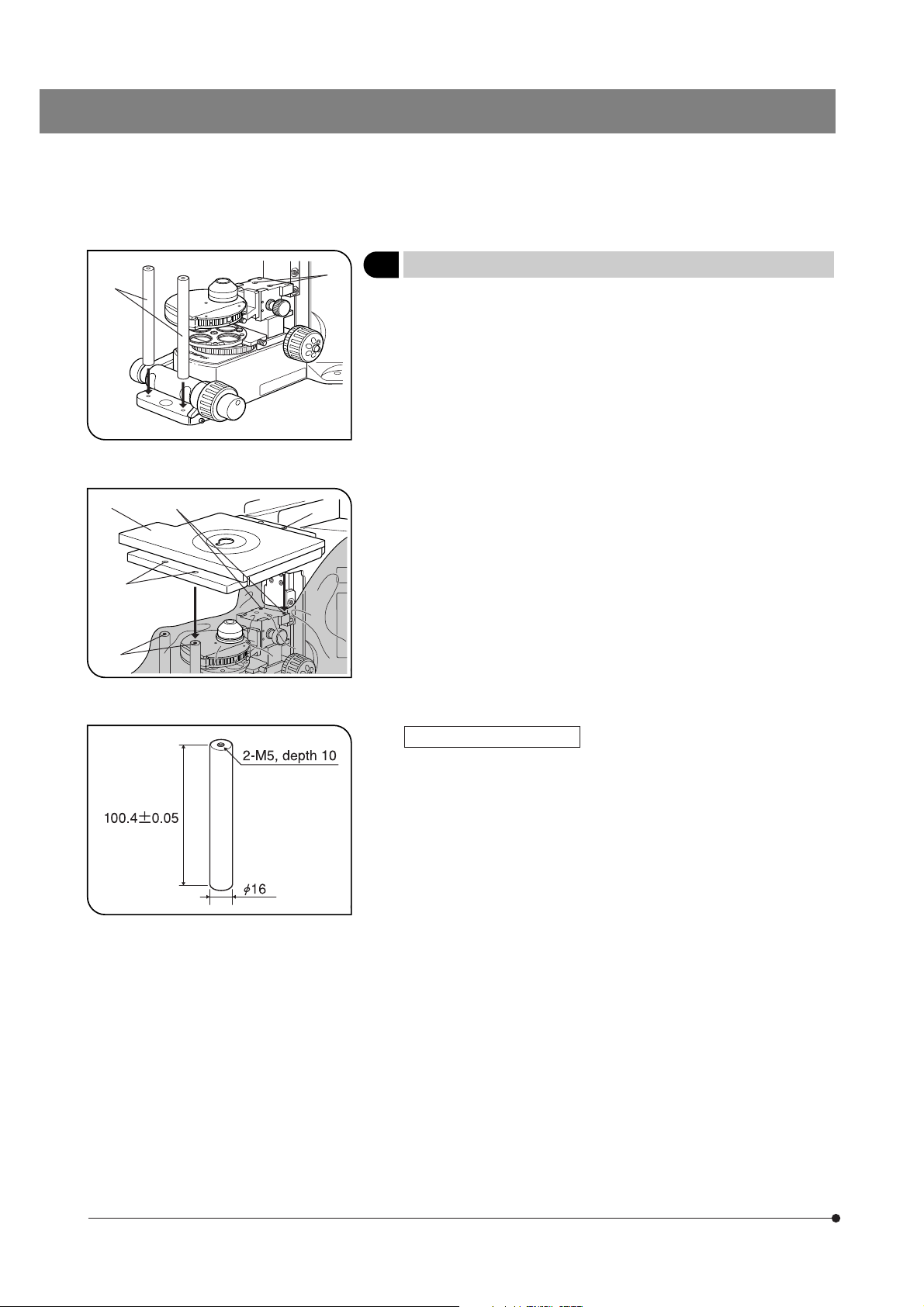
@
²
|
³
…
Fig. 55
Fig. 56
ƒ
†
7 Attaching the Cross Stage
}When using a commercially marketed bridge stage, attach it by referring
to its instruction manual.
1. Align the two WI-FSH fixed stage adapters @ with the front of the microscope base and clamp the adapters by tightening the hex-socket screws
from the bottom side using the Allen wrench provided with the microscope frame.
2. Lower the condenser, align the mounting holes ³ and ƒ of the IX-SVL2
cross stage ² with the mounting screw holes | and …, and clamp the
cross stage by tightening the hex-socket screws with the Allen wrench
provided with the microscope frame.
}When the waterproof cover is used, attach hex-socket screws to the screw
holes | and … by passing through the waterproof cover.
(Figs. 55 & 56)
Fig. 57
Lowering the Stage Height
When no condenser is used, the stage height can be lowered by 50 mm
by loosening the 2 condenser holder clamping screws († in Fig. 55) and
removing the holder.
In this case, however, the length of the WI-FSH fixed stage adapter becomes excessive. To deal with this, order custom fabrication of two support
pillars as shown in Fig. 57 or fabricate them by yourself.
42
Page 47

BX51WI
PROPER SELECTION OF THE POWER SUPPLY CORD
If no power supply cord is provided, please select the proper power supply cord for the equipment by referring to “ Specifications ” and
“ Certified Cord ” below:
CAUTION:
In case you use a non-approved power supply cord for Olympus products, Olympus can no longer warrant the
electrical safety of the equipment.
Specifications
Voltage Rating
Current Rating
Temperature Rating
Length
Fittings Configuration
125V AC (for 100-120V AC area) or, 250V AC (for 220-240V AC area)
6A minimum
60°C minimum
3.05 m maximum
Grounding type attachment plug cap. Opposite terminates in molded-on IEC configuration appliance coupling.
Table 1 Certified Cord
A power supply cord should be certified by one of the agencies listed in Table 1 , or comprised of cordage marked with an
agency marking per Table 1 or marked per Table 2. The fittings are to be marked with at least one of agencies listed in
Table 1. In case you are unable to buy locally in your country the power supply cord which is approved by one of the
agencies mentioned in Table 1, please use replacements approved by any other equivalent and authorized agencies in
your country.
Country Agency
Argentina
Australia
IRAM
SAA
Certification
Mark
Country Agency
Italy
Japan
IMQ
JET, JQA, TÜV,
UL-APEX / MITI
Certification
Mark
Austria
Belgium
Canada
Denmark
Finland
France
Germany
Ireland
ÖVE
CEBEC
CSA
DEMKO
FEI
UTE
VDE
NSAI
Netherlands
Norway
Spain
Sweden
Switzerland
United
Kingdom
U.S.A.
KEMA
NEMKO
AEE
SEMKO
SEV
ASTA
BSI
UL
43
Page 48

Table 2 HAR Flexible Cord
APPROVAL ORGANIZATIONS AND CORDAGE HARMONIZATION MARKING METHODS
Approval Organization
Comite Electrotechnique Belge
(CEBEC)
Verband Deutscher Elektrotechniker
(VDE) e.V. Prüfstelle
Union Technique de l´Electricite´
(UTE)
Instituto Italiano del Marchio di
Qualita´ (IMQ)
British Approvals Service for Electric
Cables (BASEC)
N.V. KEMA
SEMKO AB Svenska Elektriska
Materielkontrollanstalter
Österreichischer Verband für
Elektrotechnik (ÖVE)
Danmarks Elektriske Materialkontroll
(DEMKO)
Printed or Embossed Harmonization Marking (May be located on
jacket or insulation of internal wiring)
CEBEC <HAR>
<VDE> <HAR>
USE <HAR>
IEMMEQU <HAR>
BASEC <HAR>
KEMA-KEUR <HAR>
SEMKO <HAR>
<ÖVE> <HAR>
<DEMKO> <HAR>
Alternative Marking Utilizing
Black-Red-Yellow Thread (Length
of color section in mm)
Black Red Yellow
10 30 10
30 10 10
30 10 30
10 30 50
10 10 30
10 30 30
10 10 50
30 10 50
30 10 30
National Standards Authority of Ireland
(NSAI)
Norges Elektriske Materiellkontroll
(NEMKO)
Asociacion Electrotecnica Y
Electronica Espanola (AEE)
Hellenic Organization for
Standardization (ELOT)
Instituto Portages da Qualidade
(IPQ)
Schweizerischer Elektro
Technischer Verein (SEV)
Elektriska Inspektoratet
Underwriters Laboratories Inc. (UL) SV, SVT, SJ or SJT, 3 X 18AWG
Canadian Standards Association (CSA) SV, SVT, SJ or SJT, 3 X 18AWG
<NSAI> <HAR>
NEMKO <HAR>
<UNED> <HAR>
ELOT <HAR>
np <HAR>
SEV <HAR>
SETI <HAR>
30 30 50
10 10 70
30 10 70
30 30 70
10 10 90
10 30 90
10 30 90
44
Page 49

BX51WI
10
{Study the instruction manual for the lamp housing before inspection.
{For safe use of the lamp housing, we recommend performing the following inspection periodically (every time you replace
the lamp bulb and at least every 6 months).
{The table below identifies the check items to be observed. Put (X) if not applicable or ( ) if applicable.
{If there is any ( ) mark noted, immediately stop use of the product, and contact Olympus for detailed inspections or replace
the lamp housing.
{If you detect an abnormality other than that listed below or with other Olympus product, also stop the use of the product and
contact Olympus for detailed inspections.
{Note that the service, replacement and detailed inspections are charged after expiration of the warranty period.
1. More than 8 years have passed since original purchase or the total power ON
time has exceeded 20,000 hours.
2. Lamp does not light sometimes even though the main switch is set to on.
(Except discharge burners*
3. Illumination flickers when you move the lamp cable or lamp housing.
4. Lamp cable is unusually hot to the touch.
5. Scorching or burning odor is produced during use.
6. Illumination still flickers after replacement with a new lamp bulb.
(Except discharge burners*
7. Deformation, backlash, or looseness, etc. when you assemble the lamp housing. (Impossibility of removing the top section of lamp housing when you attempt to replace the lamp bulb, etc.)
8. Extreme discoloration of the lamp housing connection terminal or lamp
socket. Uneven discoloration of the left and right sections of these parts.
(Except discharge burners*
9. Discoloration, deformation or cracking of the lamp housing.
10. Melting, crack, deformation or solidification of the lamp cable or a wiring part.
11. Increased frequency of servicing compared to similar devices put into use at
the same time as the lamp housing.
LAMP HOUSING INSPECTION SHEET
If you have any questions, please contact Olympus.
Check results (Date)
Check items // / /
1
.)
1
.)
1
.)
* When the Check Result columns become insufficient, copy this sheet.
1
*
Discharge burners: Mercury burner / Xenon burner / Metall halide burner
45
Page 50

MEMO
Page 51

Page 52

EC REP
Shinjuku Monolith, 3-1, Nishi Shinjuku 2-chome, Shinjuku-ku, Tokyo, Japan
Wendenstraße 14-18, 20097 Hamburg, Germany
3500 Corporate Parkway, P.O. Box 610, Center Valley, PA 18034-0610, U.S.A.
One Corporate Drive, Orangeburg, NY 10962, U.S.A.
491B River Valley Road, #12-01/04 Valley Point Office Tower, Singapore 248373
31 Gilby Road, Mount Waverley, VIC., 3149, Australia
Blue Lagoon Drive, Suite 290 Miami, FL 33126, U.S.A.
5301
01/10
 Loading...