

Olympus BX51M Instructions Manual
INSTRUCTIONS
BX51M
SYSTEM METALLURGICAL
MICROSCOPE
This instruction manual is for the Olympus System Metallurgical Microscope Model BX51M. To
ensure the safety, obtain optimum performance and to familiarize yourself fully with the use of this
microscope, we recommend that you study this manual thoroughly before operating the microscope. Retain this instruction manual in an easily accessible place near the work desk for future
reference.
This publication is printed on 100% recycled paper
A X 7 6 0 9

NOTE: This equipment has been tested and found to comply with the limits for a Class A digital device,
pursuant to Part 15 of the FCC Rules. These limits are designed to provide reasonable protection
against harmful interference when the equipment is operated in a commercial environment. This
equipment generates, uses, and can radiate radio frequency energy and, if not installed and used in
accordance with the instruction manual, may cause harmful interference to radio communications.
Operation of this equipment in a residential area is likely to cause harmful interference in which case
the user will be required to correct the interference at his own expense.
FCC WARNING: Changes or modifications not expressly approved by the party responsible for compliance
could void the user’s authority to operate the equipment.

CONTENTS
Correct assembly and adjustments are critical for the microscope to exhibit its full performance. If you are going to
assemble the microscope yourself, please read chapter 8, “ASSEMBLY” (pages 27 to 29) carefully.
BX51M
IMPORTANT — Be sure to read this section for safe use of the equipment. —
1 NOMENCLATURE
2
REFLECTED LIGHT BRIGHTFIELD/DARKFIELD OBSERVATION PROCEDURE
3 USING THE CONTROLS
3-1 Base ........................................................................................................................................................................................................................... 7
1 Voltage Indication 2 Using the Light Intensity Preset Switch
3-2 Focusing Block ................................................................................................................................................................................... 8-9
1 Adjusting the Focus 2 Replacing the Fine Adjustment Knob
3 Adjusting the Coarse Adjustment Knob Tension 4 Pre-focusing Lever
3-3 Reflected Light Brightfield/Darkfield Illuminator (BX-RLA2)............................................ 9-11
1 Selecting the Light Path 2 Centering the Field Iris Diaphragm (FS)
3 Centering the Aperture Iris Diaphragm (AS) 4 Using the ND Filter Knob
5 Using the Filters
3-4 Stage............................................................................................................................................................................................................ 12-14
1 Placing the Specimen 2 Adjusting the X/Y-Axis Knob Tension
3 Using the Y-Axis Lock Lever 4 Rotating the Stage
5 Adjusting the Stage Height
3-5 Observation Tube ..................................................................................................................................................................... 15-16
1 Adjusting the Interpupillar Distance 2 Adjusting the Dioper
3 Using the Eye Shades 4 Using Eyepiece Micrometer Disks
5
Selecting the Light Path of the Tinocular Tube
6
Adjusting the Tilt (with the U-TBI3/SWETTR2)
1-3
4
5-6
7-16
4 OBSERVATION METHODS (Using BX-RLA2)
4-1 Reflected Light Brightfield/Darkfield Observation.............................................................................. 17
Reflected Light Nomarski DIC (Differential Interference Contrast) Observation
4-2
4-3 Reflected Light Simplified Polarized Light Observation ............................................................ 19
5 TROUBLESHOOTING GUIDE
6 SPECIFICATIONS
7 OPTICAL CHARACTERISTICS <<UIS2 (UIS) Series>>
ASSEMBLY
8
PROPER SELECTION OF THE POWER SUPPLY CORD .......................................................................
—
See this section for the replacement of the light bulb. —
17- 19
.............. 17- 1 9
20-22
23
24-26
27-29
30-31
IMPORTANT
This microscope employs a UIS2 (UIS) (Universal Infinity System) optical design, and should be used only
with UIS2 (UIS) eyepieces, objectives and condensers for the BX2 series. (Some of the modules designed for the BX series are also usable. For details, please consult Olympus or the latest catalogue.)
SAFETY PRECAUTIONS
1. Install the microscope on a sturdy, level table or bench so as not to
block the air vents on the underside of the base.
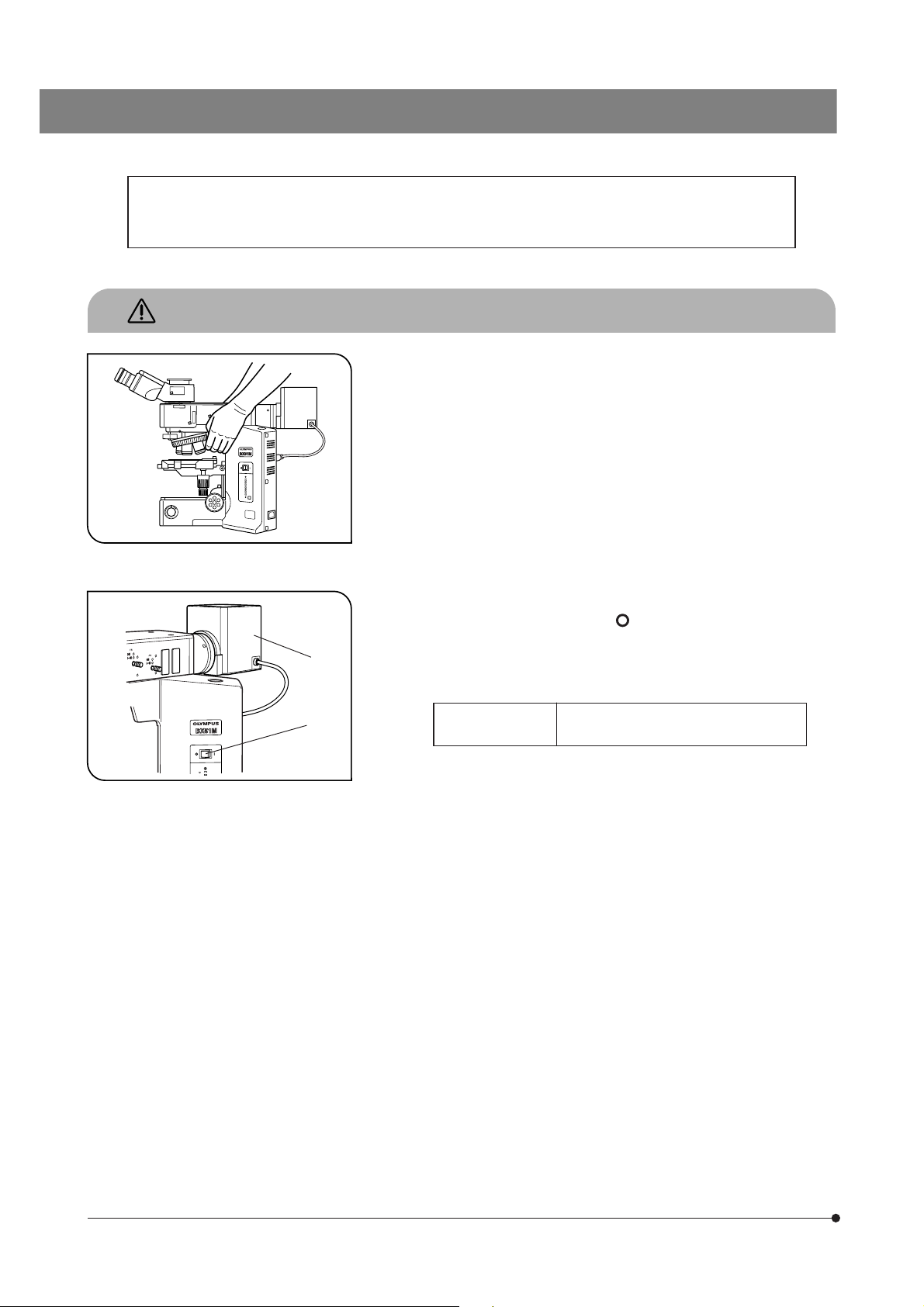
2. When moving the microscope, carefully carry it with the grasping part on
the arm as shown in Fig. 1 (Weight: approx. 15 kg).
#Damage to the microscope will occur if you grasp it by other parts
including the stage, lamp socket or tube.
#Before transporting the microscope, be sure to remove the speci-
men and eyepieces so that they will not drop. Also remove other
modules attached to the microscope because they increase the
system weight.
Fig. 1
@
3. The surface of the lamp housing @ becomes very hot during operation.
Before installing the lamp housing, be sure to reserve enough space
around, particularly above, the lamp housing.
4. To avoid potential shock hazards and burns when replacing the light
bulb, set the main switch ² to “ ” (OFF) then disconnect the power
cord from the wall outlet in advance. Whenever you replace the bulb
during use or right after use, allow the lamp housing @ and bulb to cool
before touching (Fig. 2).
Fig. 2
²
Designated
halogen bulbs
#The microscope also incorporates a fuse (this should be replaced
by the manufacturer or authorized agent).
5. Always use the power cord provided by Olympus. If no power cord is
provided, please select the proper power cord by referring to the chapter
“PROPER SELECTION OF THE POWER SUPPLY CORD” at the end of
this instruction manual. If the proper power cord is not used, product
safety and performance cannot be guaranteed.
6. Always ensure that the grounding terminal of the microscope and that
of the wall outlet are properly connected. If the equipment is not grounded,
Olympus can no longer warrant the electrical safety and performance of
the equipment.
7. Never insert metal objects, etc. into the air vents of the microscope frame
as this could result in electrical shock and personal injury.
8. The microscope system will be unstable when its height is increased by
attached accessories. Take proper measures so that the system will not
topple down.
12V100WHAL-L (PHILIPS 7724)
12V50WHAL-L (LIFE JC)
1
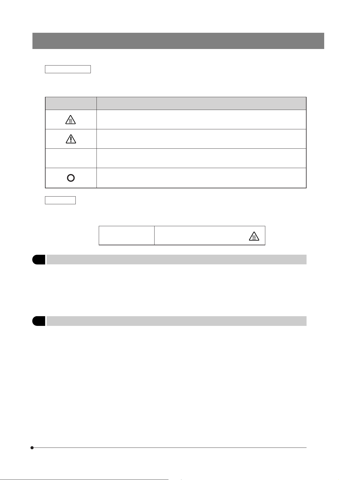
Safety Symbols
The following symbols are found on the microscope. Study the meaning of the symbols and always use the equipment in the safest possible manner.
Symbol Explanation
Indicates that the surface becomes hot, and should not be touched with bare hands.
Before use, carefully read the instruction manual. Improper use could result in personal injury to
the user and/or damage to the equipment.
BX51M
l
Warnings
Warning engraving/stickers are placed at parts where special precaution is required when handling and using the
microscope. Always heed the warnings.
Indicates that the main switch is ON.
Indicates that the main switch is OFF.
Warning engraving
position
Lamp housing (U-LH100-3)
(Warning against high temperature)
1 Getting Ready
1. A microscope is a precision instrument. Handle it with care and avoid subjecting it to sudden or severe impact.
2. Do not use the microscope where it is subjected to direct sunlight, high temperature and humidity, dust or vibrations. (For
the operating conditions, refer to chapter 6, “SPECIFICATIONS”.)
3. The BX51M can be used with an intermediate attachment such as a U-CA magnification changer or U-EPA2 eyepoint
adjuster.
2 Maintenance and Storage
1. To clean the lenses and other glass components, simply blow dirty away using a commercially available blower and wipe
gently using a piece of cleaning paper (or clean gauze).
If a lens is stained with fingerprints or oil smudges, wipe it gauze slightly moistened with commercially available absolute
alcohol.
!Since the absolute alcohol is highly flammable, it must be handled carefully.
Be sure to keep it away from open flames or potential sources of electrical sparks –– for example, electrical
equipment that is being switched on or off.
Also remember to always use it only in a well-ventilated room.
2. Do not attempt to use organic solvents to clean the microscope components other than the glass components. To clean
them, use a lint-free, soft cloth slightly moistened with a diluted neutral detergent.
3. Never attempt to disassemble any part of the microscope.
4. When not using the microscope, make sure that the lamp socket has cooled down sufficiently and then cover the
microscope with a dust cover.
5. When disposing of the microscope, check the ordinances and rules of your local authority and follow them.
2

3 Caution
If the microscope is used in a manner not specified by this manual, the safety of the user may be imperiled. In addition,
the equipment may also be damaged. Always use the equipment as outlined in this instruction manual.
The following symbols are used to set off text in this instruction manual.
! : Indicates that failure to follow the instructions in the warning could result in bodily harm to the
user and/or damage to equipment (including objects in the vicinity of the equipment).
# : Indicates that failure to follow the instructions could result in damage to equipment.
} : Indicates commentary (for ease of operation and maintenance).
3
BX51M
1
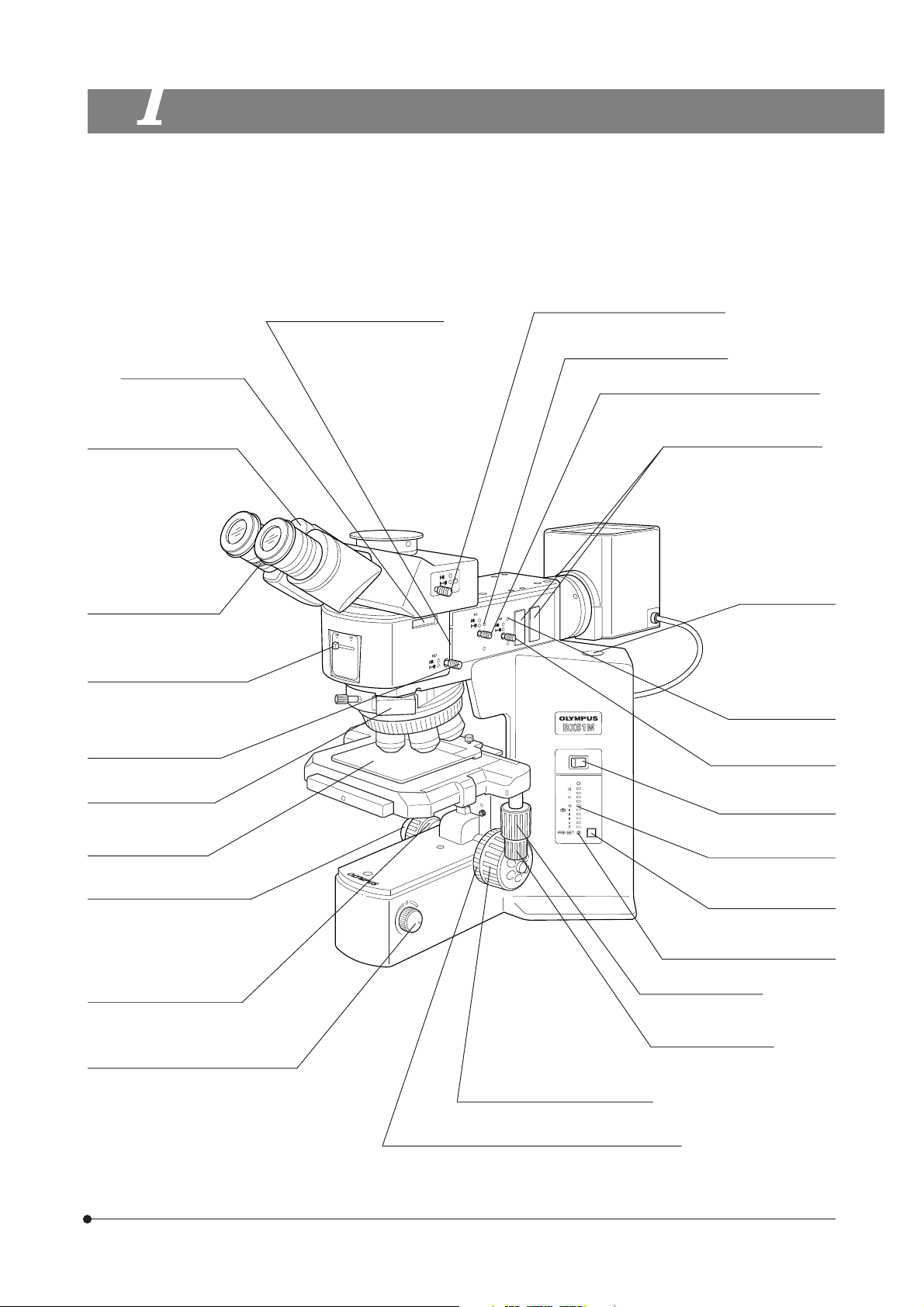
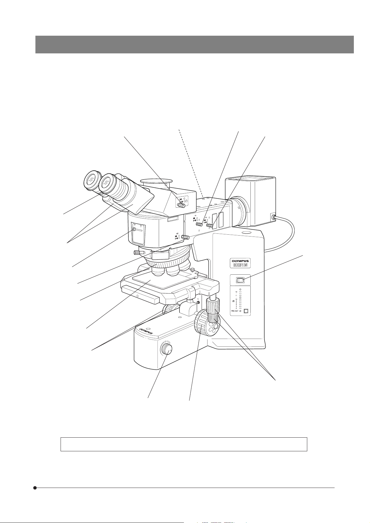
NOMENCLATURE
}If you have not yet assembled the microscope, read chapter 8, “ASSEMBLY” (pages 27 to 29).
}This illustration shows the BX-51RF microscope frame with the BX-RLA2 reflected light brightfield/darkfield illuminator in-
stalled on it. For the nomenclature of the BX-URS2 universal illuminator, please refer to its instruction manual.
Analyzer insertion slot
(Page 17)
Interpupillary distance
adjustment scale (Page 15)
Diopter adjustment ring
(Page 15)
Mirror selector lever (Page 9)
ND filter knob (Page 11)
DIC slider insertion slot
(Page 18)
Polarizer insertion slot (Page 17)
Light path selector knob (Page 16)
FS centering screw (Page 10)
Field iris diaphragm (FS) knob (Page 10)
Filter insertion slot (Page 11)
#The filter should be inserted
from the left.
Aperture iris diaphragm
I
O
(AS) knob (Page 10)
Allen screwdriver
(accommodation
position)
AS centering screw
(Page 10)
Main switch (Page 1)
Stage plate (Page 12)
Fine adjustment knob (Page 8)
(Detachable)
Pre-focusing lever (Page 9)
Brightness adjustment knob (Page 7)
(Lamp voltage adjustment knob)
Lamp voltage indicator
(Page 7)
Light intensity preset
switch (Page 7)
Light intensity preset adjustment
screw (Page 7)
Y-axis knob (Page 13)
X-axis knob (Page 13)
Coarse adjustment knob (Page 8)
Coarse adjustment tension adjustment ring (Page 8)
4

REFLECTED LIGHT BRIGHTFIELD/DARKFIELD
OBSERVATION PROCEDURE
}The following flow shows the basic operating procedure for reflected light brightfield or darkfield observation. The operating
procedures for polarized light and Nomarski DIC observations will be described separately in their descriptions.
(Controls Used) (Page)
Select the brightfield (BF) or darkfield (DF) observation.
Set the main switch to “ I ” (ON).
Disengage the analyzer, polarizer,
filter, etc. from the light path.
Check interlocking of the ND filter.
Select the light path (trinocular tube only).
Place the specimen on the stage.
Engage the 10X objective in the light path.
Bring the specimen in focus.
@ Mirror selector lever (P. 9)
² Main switch
³ ND filter knob (P. 11)
| Light path selector knob (P. 16)
ƒ Stage plate (P. 12)
… X/Y-axis knobs (P. 13)
† Revolving nosepiece
‡ Coarse/fine adjustment knobs (P. 8)
Adjust the brightness.
Adjust the interpupillary distance.
Adjust the diopter.
Adjust the aperture iris diaphragm and field iris
diaphragm.
} Open both iris diaphragms in case of DF ob-
servation.
Engage the desired objective in the light path
and bring the specimen in focus.
Insert the required filters.
Adjust the brightness.
Start observation.
Š Brightness adjustment knob (P. 7)
‰ Binocular tube (P. 15)
‹ Diopter adjustment ring (P. 15)
ΠAS knob (P. 10)
™ FS knob (P. 10)
† Revolving nosepiece
‡ Coarse/fine adjustment knobs (P. 8)
š Filter insertion slot (P. 11)
Š Brightness adjustment knob (P. 7)
5
|
Insertion from the left
š
BX51M
™
Œ
‹
‰
@
³
†
ƒ
‡
²
I
O
…
Š
} Make a photocopy of the observation procedure pages and post it near your microscope.
‡
6
USING THE CONTROLS
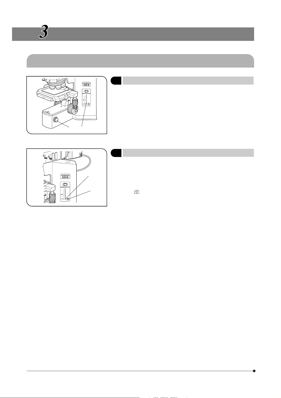
3-1 Base
Fig. 3
Fig. 4
@
²
²
@
1 Voltage Indication
1. Turn the brightness adjustment knob @ clockwise to increase the voltage and make illumination brighter.
2. The numerals on the left of the lamp voltage LEDs ² indicate the approximate voltage.
2 Using the Light Intensity Preset Switch
}The light intensity preset switch @ makes it possible to limit the light
intensity to a preselected level regardless of the position of the brightness adjustment knob. The light intensity preset switch has been preset
before factory shipment to a position which can provide optimum color
reproduction when the U-25LBD filter is engaged in the light path (approx.
9 V mark).
1. Press the light intensity preset switch @ to the ON position. (The switch
lights when it is ON.)
2. Using a small flat-blade screwdriver, turn the preset adjustment screw ²
to obtain the required light intensity. Turning the screw clockwise increases
brightness.
3. When the light intensity preset switch is set to OFF, the brightness returns
to the level set by the brightness adjustment knob.
}While the light intensity preset switch is ON, turning the brightness ad-
justment knob does not affect brightness.
(Fig. 3)
(Fig. 4)
7
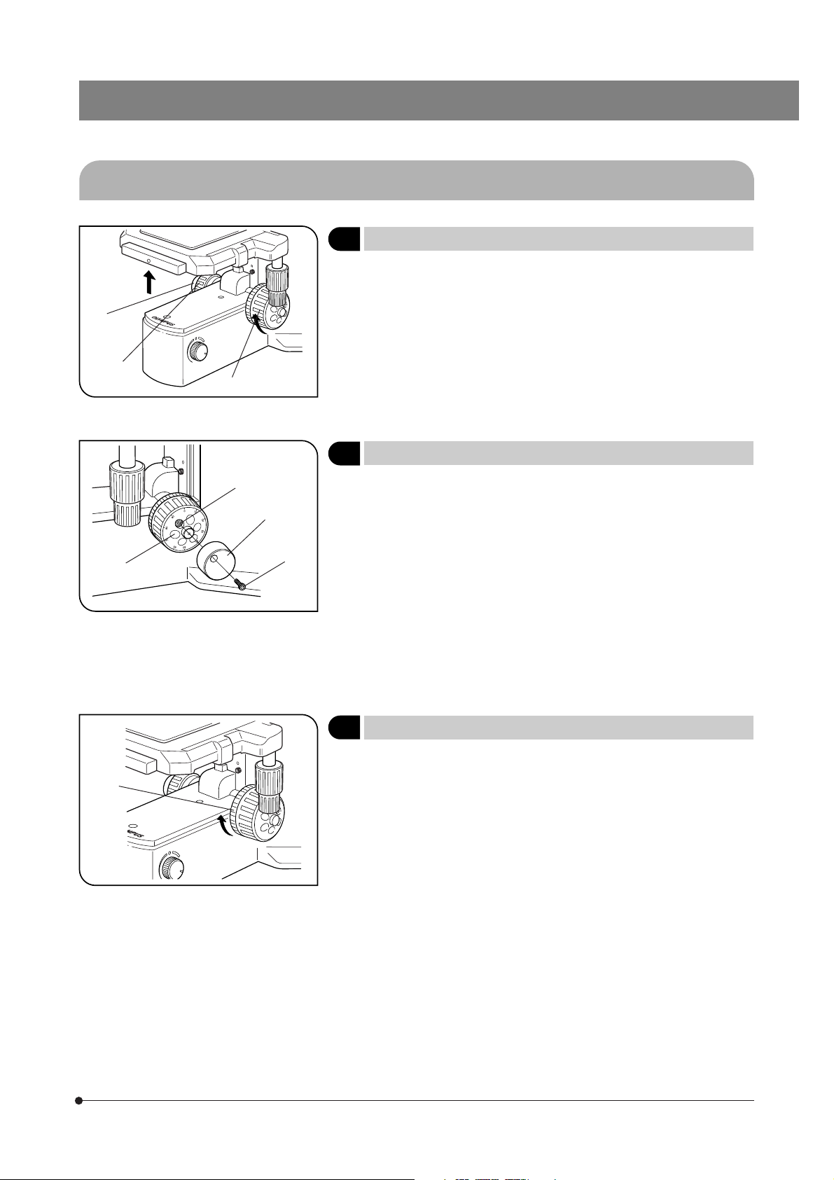
3-2 Focusing Block
BX51M
²
@
³
Fig. 5
Fig. 6
@
|
²
@
1 Adjusting the Focus
The coarse adjustment knob @ and fine adjustment knob ² are designed to raise the stage (i.e. to let the specimen approach the objective)
when they are rotated in the direction of the arrows.
2 Replacing the Fine Adjustment Knob
#The fine adjustment knob has been attached on the right side at the
factory.
}The fine adjustment knob is designed detachable to prevent interference
with hand during manipulation of the stage feed knobs. Usually attach
the knob on the opposite side to the stage feed knobs.
1. Loosen the clamping screw @ using the Allen screwdriver, and remove
the fine adjustment knob ².
2. Remove the seal from the fine adjustment knob screw hole on the other
side and attach the knob by reversing the removal procedure.
3. Attach one of the provided seals on the screw hole | of the removed
fine adjustment knob.
}The fine adjustment dial ³ can be operated with your fingertip or finger
surface.
(Fig. 5)
(Fig. 6)
@
Fig. 7
3
Adjusting the Coarse Adjustment Knob Tension
#The rotation tension of the coarse adjustment knob should be ad-
justed using the tension adjustment ring.
The coarse adjustment knob tension is preadjusted for easy use. However, if desired, you can change the tension using the tension adjustment ring @. Turning the ring in the direction of the arrow increases
tension, and vice versa.
The tension is too low if the objective drops by itself or focus is quickly
lost after adjustment with the fine adjustment knob. In this case, turn the
ring in the direction of the arrow to increase tension.
(Fig. 7)
8
 Loading...