

Page 1
INSTRUCTIONS
BX51/BX52
SYSTEM MICROSCOPE
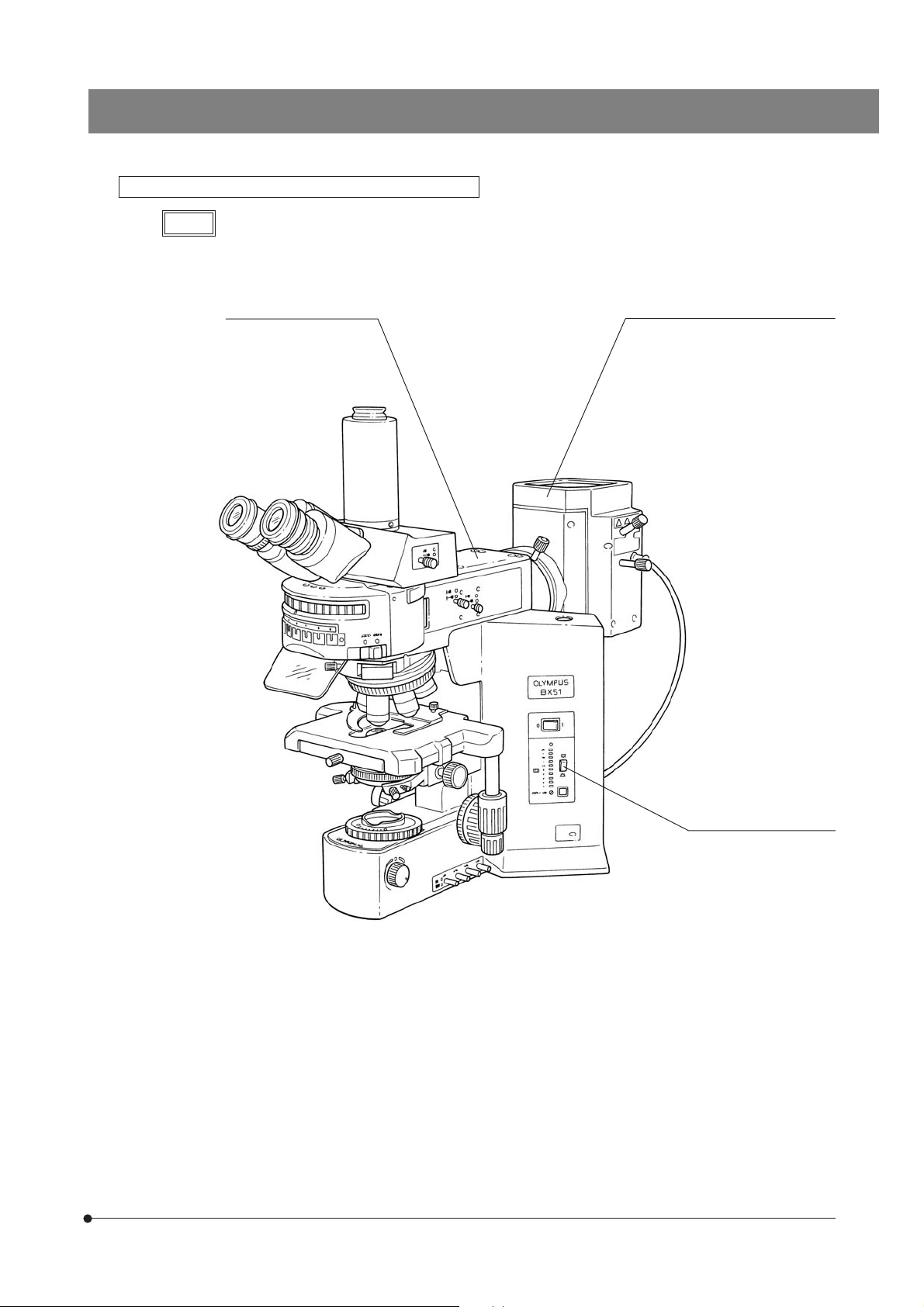
This instruction manual is for the Olympus System Microscopes Models BX51 and BX52. To ensure
the safety, obtain optimum performance and to familiarize yourself fully with the use of this microscope, we recommend that you study this manual thoroughly before operating the microscope.
Retain this instruction manual in an easily accessible place near the work desk for future reference.
This publication is printed on 100% recycled paper
A X 7 3 4 0
Page 2

Page 3

BX51/BX52
CONTENTS
Correct assembly and adjustments are critical for the microscope to exhibit its full performance. If you are going to assemble
the microscope yourself, please read section 7, “ASSEMBLY” (pages 28 to 30) carefully.
IMPORTANT — Be sure to read this section for safe use of the equipment. —
1 NOMENCLATURE
TRANSMITTED LIGHT BRIGHTFIELD OBSERVATION PROCEDURE
2
3 USING THE CONTROLS
3-1 Base ................................................................................................................................................................................................................. 8-10
1 Voltage Indication 2 Using the Light Intensity Preset Switch 3 Using the Filters
3-2 Focusing Block ...................................................................................................................................................................................... 11
1 Replacing the Fine Adjustment Knob
2 Adjusting the Coarse Adjustment Knob Tension 3 Pre-focusing Lever
3-3 Stage............................................................................................................................................................................................................ 12-14
1 Placing the Specimen 2 Adjusting the X- and Y-Axis Knob Tension
3 Rotating the Stage 4 Adjusting the Stage Height
3-4 Observation Tube ...................................................................................................................................................................... 15-17
1 Adjusting the Interpupillar Distance 2 Adjusting the Diopter
3 Using the Eye Shades 4 Using the Eyepiece Micrometer Disk
5 Selecting the Light Path of the Trinocular Tube
6 Adjusting the Tilt
3-5 Condenser.......................................................................................................................................................................................... 18-19
1 Centering the Condenser 2 Compatibility of Objectives and Condensers
3-6 Immersion Objectives................................................................................................................................................................. 20
1 Using Immersion Objectives
3-7 Objectives with Correction Collar ............................................................................................................................. 20
1-3
4-5
6-7
8-20
4 TROUBLESHOOTING GUIDE
5 SPECIFICATIONS
6 OPTICAL CHARACTERISTICS
7 ASSEMBLY
PROPER SELECTION OF THE POWER SUPPLY CORD....................................................................
— See this section for the replacement of the light bulb. —
(UIS2/UIS Series)
21-23
24-25
26-27
28-30
31-32
Page 4

Page 5
BX51/BX52
IMPORTANT
This microscope employs a UIS2/UIS (Universal Infinity System) optical design, and should be used
only with UIS2/UIS eyepieces, objectives and condensers for the BX2 series. (Some of the modules
designed for the BX series and objectives/eyepieces for the UIS series are also usable. For details,
please consult Olympus or the catalogues.) Less than optimum performance may result if inappropriate
accessories are used.
SAFETY PRECAUTIONS
@
(Fig. 1)
1. After the equipment has been used in an observation of a specimen that
is accompanied with a potential of infection, clean the parts coming in
contact with the specimen to prevent infection.
· Moving this product is accompanied with the risk of dropping the
specimen. Be sure to remove the specimen before moving this
product.
· In case the specimen is damaged by erroneous operation, promptly
take the infection prevention measures.
· The product becomes unstable if its height is increased by an accessory
mounted on it. In this case, take anti-toppling measures to prevent the
specimen from being dropped when the product topples down.
2. Install the microscope on a sturdy, level table or bench so as not to block
the air vents on the underside of the base.
Do not place the microscope on a flexible surface, as this could result in
blocking the air vents and cause overheating or a fire.
3. The surfaces of the lamp housing on the rear of the microscope will
become extremely hot during operation. When installing the microscope,
make sure to allow ample free space (10 cm or more) around and in
particular above the lamp housing.
4. When installing the microscope, route the power cord away from the
lamp housing. Should the power cord come in contact with the hot lamp
housing, the power cord could melt and cause electric shock.
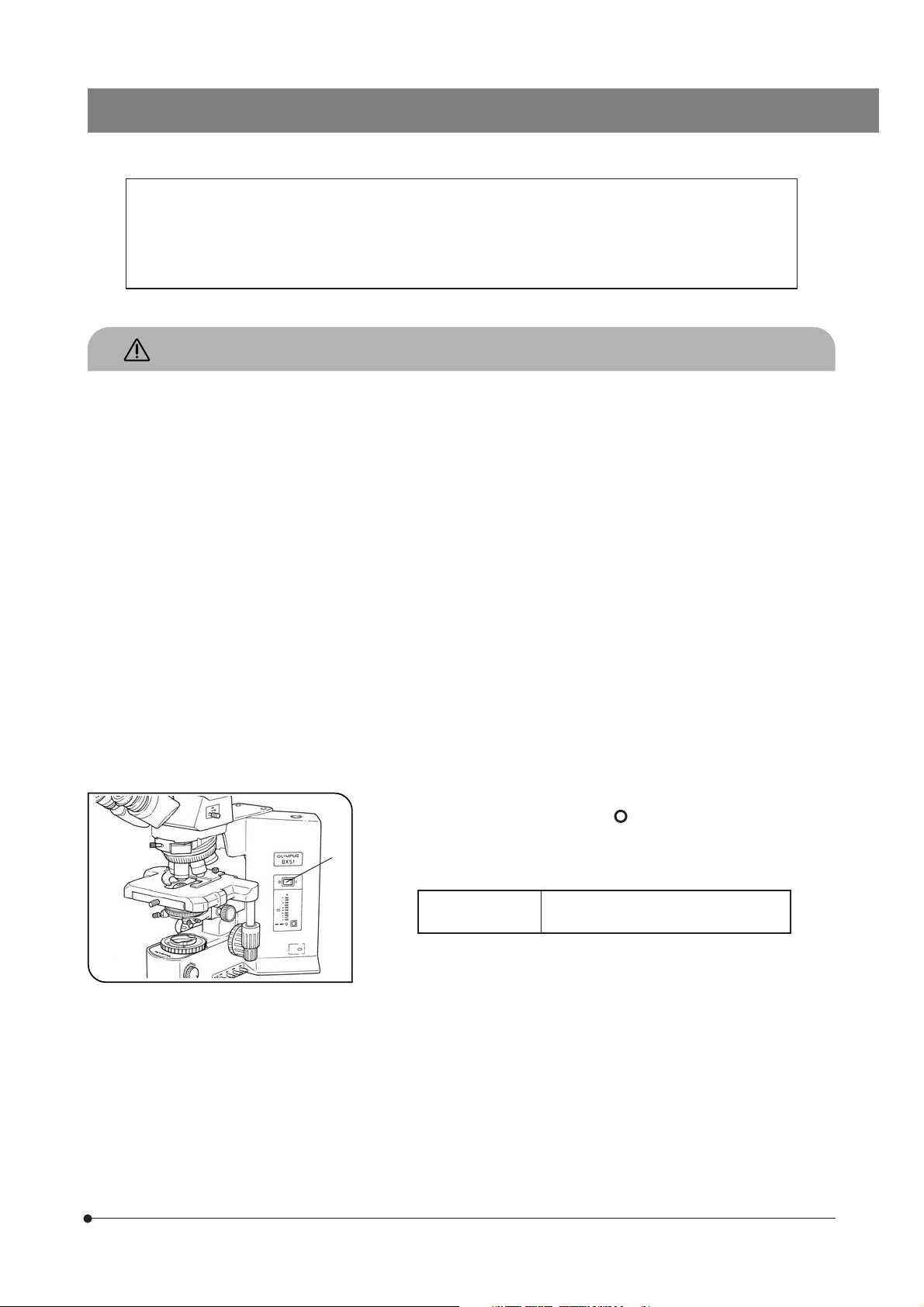
5. To avoid potential shock hazards and burns when replacing the light
bulb, set the main switch @ to “
cord from the wall outlet in advance. Whenever you replace the bulb
during use or right after use, allow the lamp housing‚ and bulb to cool
before touching. (Fig. 1)
” (OFF) then disconnect the power
Fig. 1
Designated bulb
#The microscope also incorporate a fuse (this should be replaced by
the manufacturer or an authorized agent).
6. Always use the power cord provided by Olympus. If no power cord is
provided, please select the proper power cord by referring to the section
“PROPER SELECTION OF THE POWER SUPPLY CORD” at the end of
this instruction manual. If the proper power cord is not used, product
safety performance cannot be warranted.
7. Always ensure that the grounding terminal of the microscope and that
of the wall outlet are properly connected. If the equipment is not grounded,
Olympus can no longer warrant the electrical safety performance of the
equipment.
8. Never insert metallic objects into the air vents of the microscope frame
as this could result in electrical shock, personal injury and equipment
damage.
12V100WHAL (PHILIPS 7724)
12V50WHAL-L (LIFE JC)
1
Page 6
Safety Symbols
The following symbols are found on the microscope. Study the meaning of the symbols and always use the equipment
in the safest possible manner.
Symbol Explanation
Indicates that the surface becomes hot, and should not be touched with bare hands.
Before use, carefully read the instruction manual. Improper use could result in personal injury to
the user and/or damage to the equipment.
l
Indicates that the main switch is ON.
Indicates that the main switch is OFF.
Warnings
Warning engraving is placed at parts where special precaution is required when handling and using the microscope.
Always heed the warnings.
Warning engraving
position
Lamp housing
(Warning against high temperature)
1 Getting Ready
1. A microscope is a precision instrument. Handle it with care and avoid
subjecting it to sudden or severe impact.
2. Do not use the microscope where it is subjected to direct sunlight, high
temperature and humidity, dust or vibrations. (For the operating conditions, refer to section 5, “SPECIFICATIONS”.)
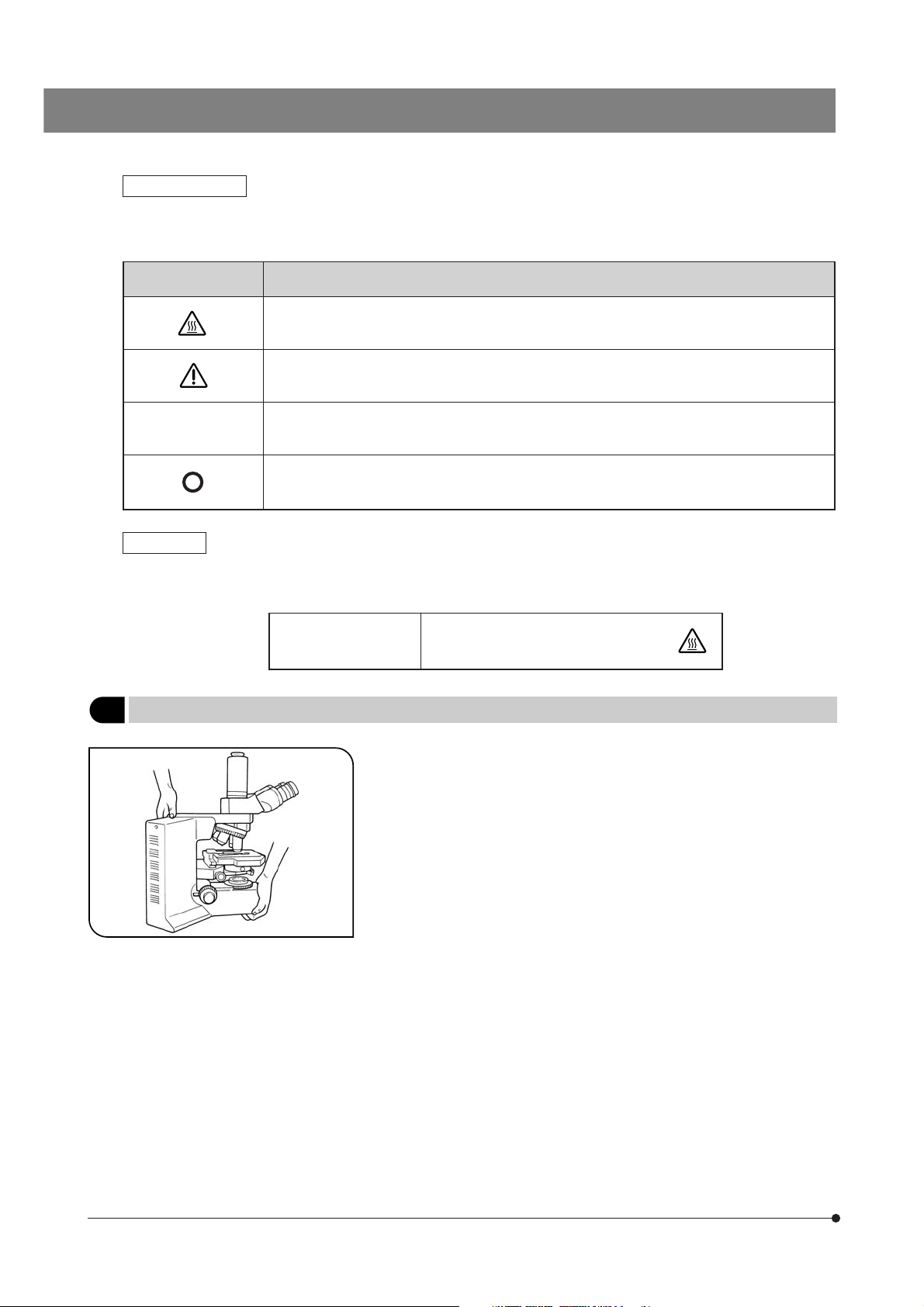
3. When moving the microscope, remove the specimen and modules that
may drop during transport and carefully carry it with the grasping part
on the rear of the arm and the base as shown in Fig. 2 (Weight: approx.
16 kg).
#If a module such as a photographic device is installed, the micro-
Fig. 2
scope system will be very heavy. Remove the intermediate attachment before carrying.
#Damage to the microscope will occur if you grasp it by the stage,
coarse/fine adjustment knob or binocular section of the observation tube.
4. The BX51/52 series can be used with up to two intermediate attachments (e.g. a U-CA magnification changer, U-EPA2 eyepoint adjuster, etc.).
For restrictions when using two intermediate attachments, make sure to
read the instruction manual provided with the respective intermediate
attachments.
# The microscope may become unstable when its height is increased
by mounting certain modules on it. In such a circumstance, take
measures to prevent the microscope from toppling down and
dropping the specimen.
2
Page 7

BX51/BX52
2 Maintenance and Storage
1. Clean all glass components by wiping gently with gauze. To remove fingerprints or oil smudges, wipe with gauze slightly
moistened with a mixture of ether (70%) and alcohol (30%).
Since solvents such as ether and alcohol are highly flammable, they must be handled carefully. Be sure to keep
these chemicals away from open flames or potential sources of electrical sparks –– for example, electrical equipment that is being switched on or off. Also remember to always use these chemicals only in a well-ventilated
room.
2. Do not attempt to use organic solvents to clean the microscope components other than the glass components. To clean
them, use a lint-free, soft cloth slightly moistened with a diluted neutral detergent.
3. Do not disassemble any part of the microscope as this could result in malfunction or reduced performance.
4. When not using the microscope, keep it covered with a dust cover.
3 Caution
If the microscope is used in a manner not specified by this manual, the safety of the user may be imperiled. In addition, the
equipment may also be damaged. Always use the equipment as outlined in this instruction manual.
The following symbols are used to set off text in this instruction manual.
: Indicates that failure to follow the instructions in the warning could result in bodily harm to the
user and/or damage to equipment (including objects in the vicinity of the equipment).
# : Indicates that failure to follow the instructions could result in damage to equipment.
} : Indicates commentary (for ease of operation and maintenance).
This device complies with the requirements of directive 98/79/EC concerning in vitro diagnostic
medical devices. CE marking means the conformity to the directive.
NOTE: This equipment has been tested and found to comply with the limits for a Class A digital device,
pursuant to Part 15 of the FCC Rules. These limits are designed to provide reasonable protection
against harmful interference when the equipment is operated in a commercial environment. This
equipment generates, uses, and can radiate radio frequency energy and, if not installed and used in
accordance with the instruction manual, may cause harmful interference to radio communications.
Operation of this equipment in a residential area is likely to cause harmful interference in which case
the user will be required to correct the interference at his own expense.
FCC WARNING: Changes or modifications not expressly approved by the party responsible for compliance
could void the user’s authority to operate the equipment.
3
Page 8
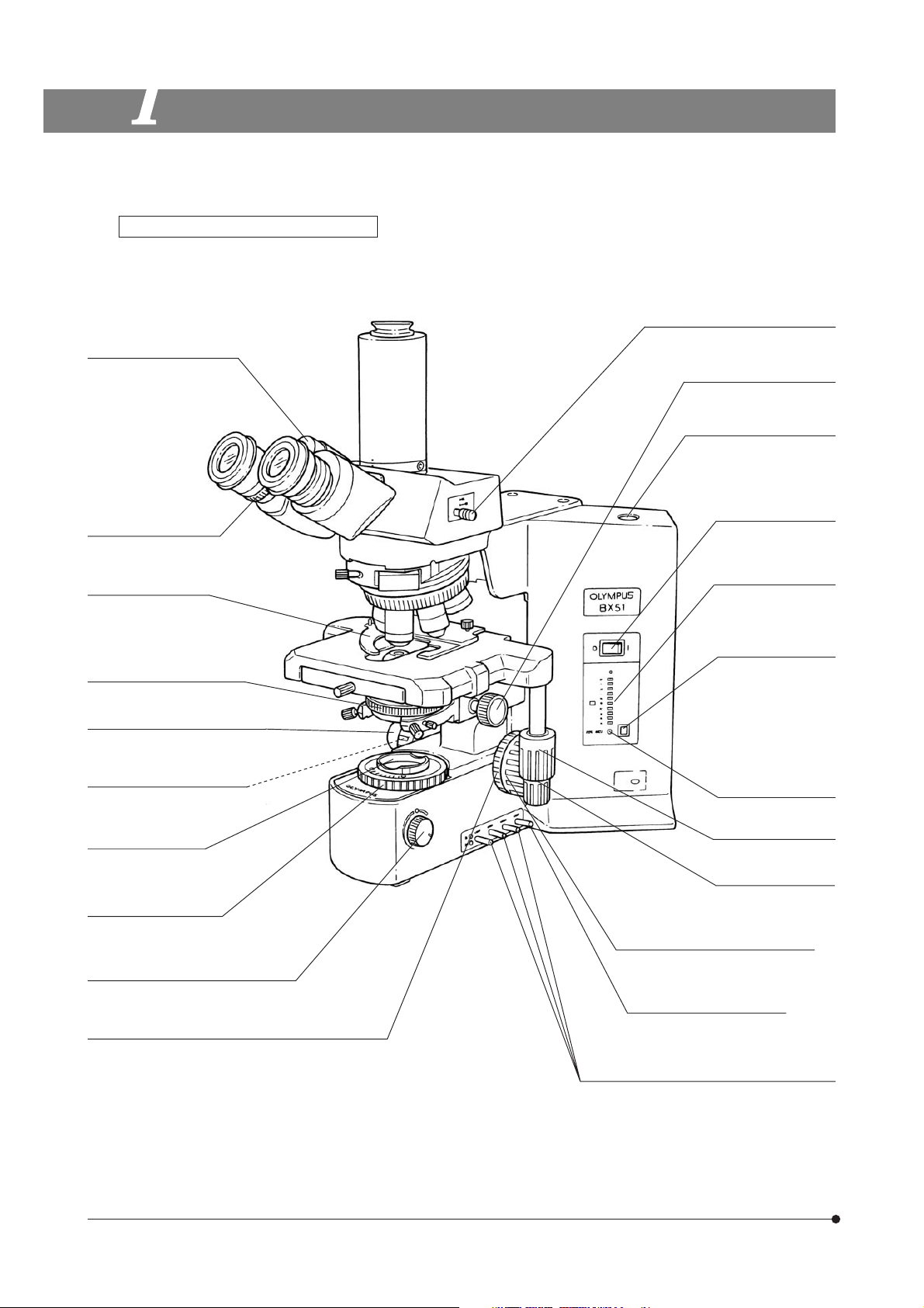
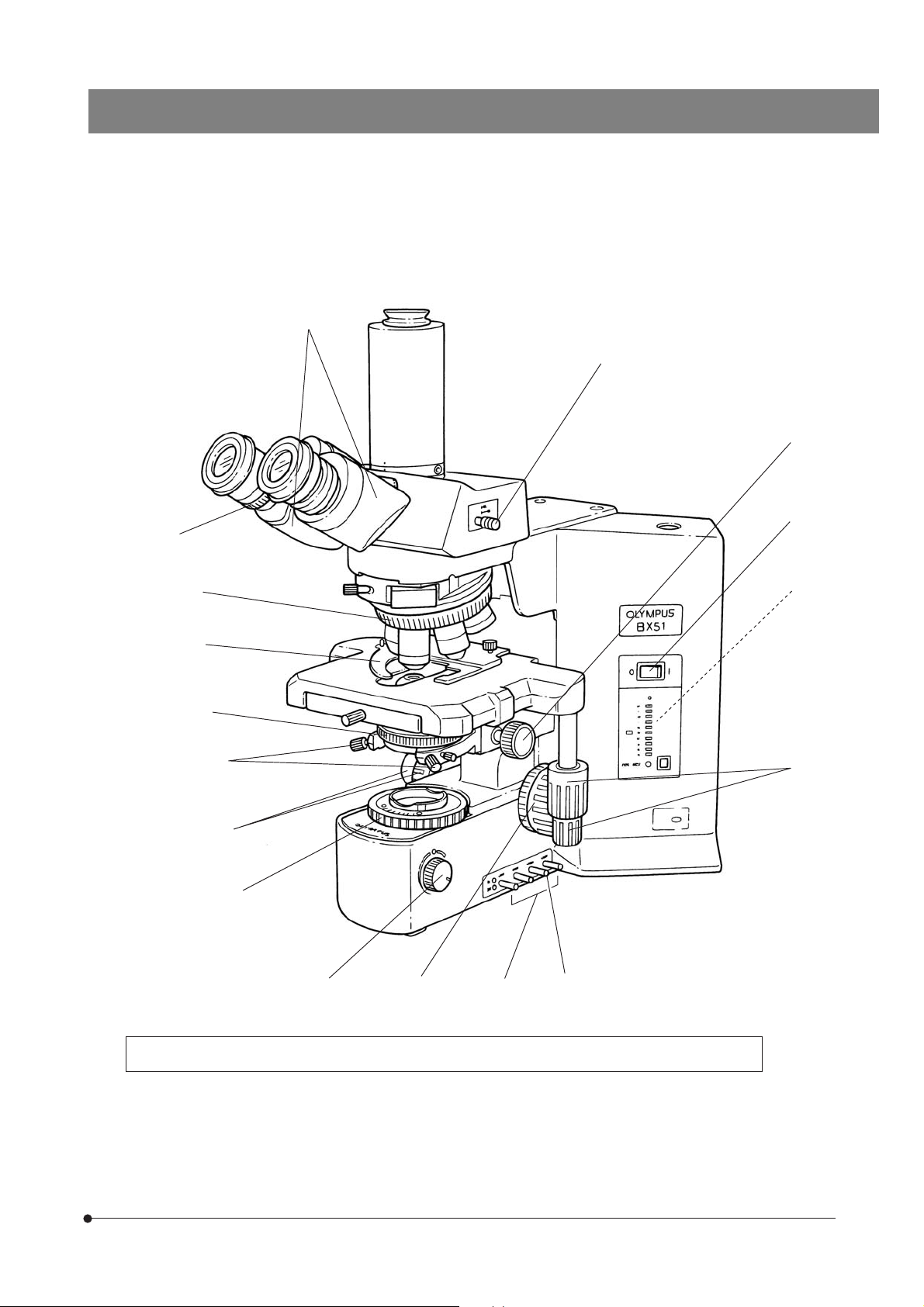
NOMENCLATURE
1
} If you have not yet assembled the microscope, read section 7, “ASSEMBLY” (pages 28 to 30).
Transmitted light specification models
Interpupillary distance
adjustment scale (Page 15)
Diopter adjustment ring
(Page 15)
Slide holder (Page 12)
Aperture iris diaphragm ring
(Page 19)
BX51TF or BX52TF microscope frame
Light path selector knob (Page 16)
Condenser height
adjustment knob (Page 18)
Allen screwdriver
(accommodation position)
Main switch (Page 1)
Voltage indicator LED
Light intensity preset
switch (Page 8)
Fine adjustment knob (Page 11)
(Detachable)
Pre-focusing Lever (Page 11)
Filter mount (Page 9)
Field iris diaphragm ring
(Page 18)
Brightness adjustment knob (Page 8)
(Lamp voltage adjustment knob)
Coarse adjustment tension adjustment ring (Page 11)
Light intensity preset
adjustment screw
(Page 8)
Y-axis knob (Page 13)
X-axis knob (Page 13)
Coarse adjustment knob (Page 11)
Optional filter knob (Page 9)
Filter knobs (Page 9)
ND6, ND25 and LBD from the front to the rear
4
Page 9
Transmitted light/reflected light specification models BX51TRF and BX52TRF microscope frames
BX51/BX52
NOTE
The controls are identical to those of the transmitted light specification models except for the transmitted/
reflected light switch and the reflected light system (vertical illuminator, reflected lamp housing).
Reflected light illuminator*
· Universal illuminator
(BX-URA2)
· Fluorescence illuminator
(BX-RFA)
· Vertical illuminator
(BX-RLA2)
· 100 W mercury burner housing
(U-LH100HG)
· 100 W mercury apo-burner housing
(U-LH100HGAPO)
· 75 W xenon lamp housing
(U-LH75XEAPO)
· 100 W halogen lamp housing
(U-LH100-3)
· System lamp housing
(U-ULH, halogen bulb specification)
Reflected lamp housing*
Transmitted/reflected light
switch
(for exclusive use with
the halogen light source)
* For the reflected illuminators and reflected lamp housings, please also refer to their instruction manuals.
5
Page 10
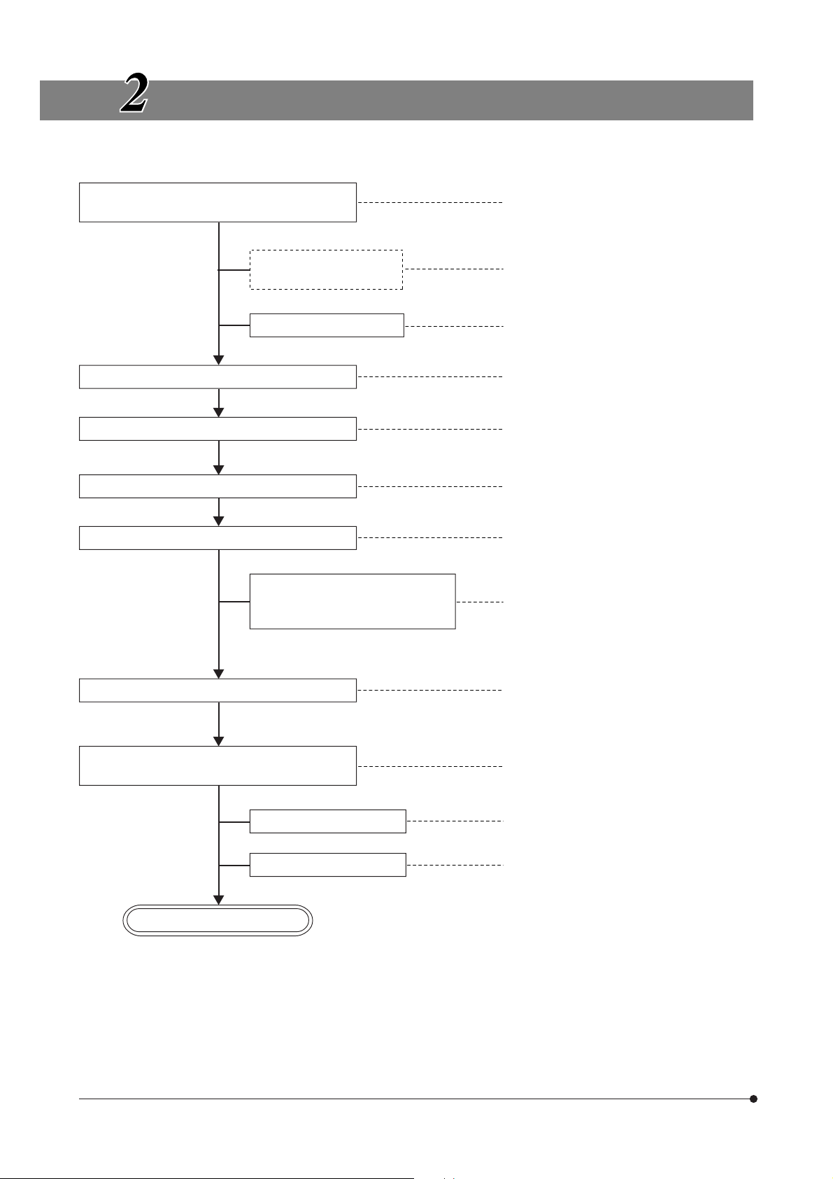
TRANSMITTED LIGHT BRIGHTFIELD OBSERVATION PROCEDURE
(Controls Used)
Set the main switch to “ I ” (ON) and adjust the
brightness.
Set the transmitted light
(BX51TRF/BX52TRF only)
Engage only the LBD filter.
Select the light path (trinocular tube).
Place the specimen on the stage.
Engage the 10X objective in the light path. ‡Revolving nosepiece
Bring the specimen in focus.
@Main switch
²Brightness adjustment knob
³Transmitted/reflected light
switch
|LBD filter knob
ƒLight path selector knob
…Slide holder
†X-/Y-axis knobs
ŠCoarse/fine adjustment knobs
(Page)
(P. 8)
(P. 5)
(P. 9)
(P. 16)
(P. 12)
(P. 13)
(P. 11)
Adjust the interpupillary distance.
Adjust the diopter.
Adjust the light axis.
Adjust the aperture iris and field iris diaphragms.
Engage the objective to be used in the light path
and bring the specimen in focus.
Engage the required filters. œFilters
Adjust the brightness. ²Brightness adjustment knob
Start observation.
‰Binocular tube
‹Diopter adjustment ring
ŒCondenser height adjustment
knob
™Condenser centering knob
šAperture iris diaphragm ring
›Field iris diaphragm ring
‡Revolving nosepiece
ŠCoarse/fine adjustment knobs
(P. 15)
(P. 15)
(P. 18)
(P. 18)
(P. 19)
(P. 18)
(P. 11)
(P. 9)
(P. 8)
6
Page 11
‹
BX51/BX52
‰
ƒ
Œ
@
‡
…
š
™
Š
›
²
Š
œ
³
†
|
} Copy the observation procedure pages on separate sheets and post it near your microscope.
7
Page 12
USING THE CONTROLS
3-1 Base
@
Fig. 3
Fig. 4
²
²
@
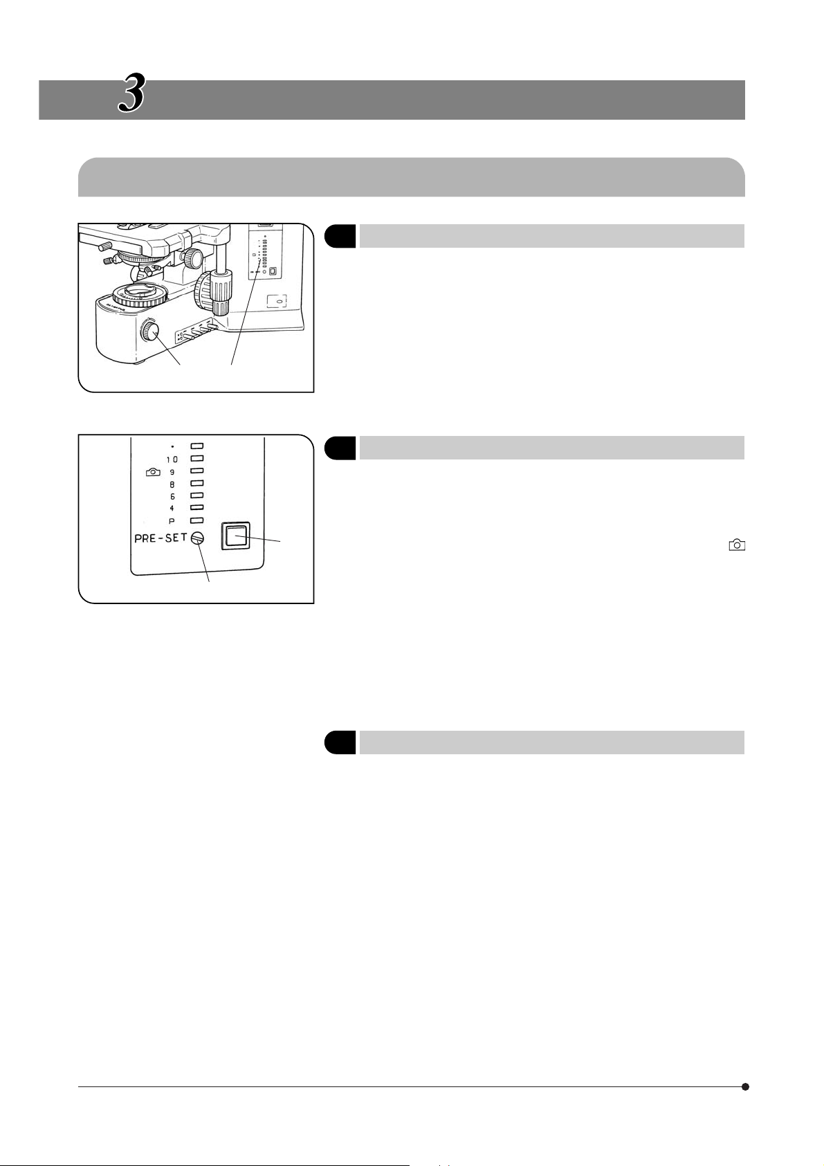
1 Voltage Indication
1. Turn the brightness adjustment knob @ clockwise to increase the voltage and make illumination brighter.
2. The numerals to the right of the lamp voltage indicator LEDs ² indicate
the voltage.
2 Using the Light Intensity Preset Switch
}The light intensity preset switch @ makes it possible to limit the light
intensity to a preselected level regardless of the position of the brightness adjustment knob.
The light intensity preset has been preset to optimum brightness for
photography when the built-in LBD filter is engaged (approx. 9 V with
marking).
1. Press the light intensity preset switch @ to the ON position. (The face of
the switch lights when it is ON.)
2. Using a small flat-blade screwdriver, turn the preset adjustment screw ²
to obtain the required light intensity. Turning the screw clockwise increases
brightness.
3. When the light intensity preset switch is set to OFF, the brightness returns
to the level set by the brightness adjustment knob.
#While the light intensity preset switch is ON, turning the light bright-
ness adjustment knob does not affect brightness.
(Fig. 3)
(Fig. 4)
8
3 Using the Filters
}You can place a filter in the light path with one of the following methods.
· Push in the knob of the desired built-in filter to engage it in the light path.
· Place a filter on the filter mount on the base and engage in the light path.
· Insert a filter in the U-FC filter cassette, attach it on the filter mount and
engage it in the light path by sliding the filter lever. (Page 9)
(Figs. 5 - 10)
(Page 9)
(Page 9)
Page 13

BX51/BX52
Using Built-In Filters (Fig. 5)
Each of filter knobs @ to | can be engaged into the light path by pressing the knob in. Pressing the button again disengages the filter from the
light path.
Filter Type/Purpose
@²³|
Fig. 5
ƒ
Fig. 6
Fig. 7
…
@ ND6
²
³
|
* Ask your Olympus representative to mount the filters.
Mounting a Single Filter (Fig. 6)
A filter with a diameter of 45 mm ƒ can be placed on the filter mount on
the base. If you need to place multiple filters, please purchase the U-FC
filter cassette.
# Even when a filter cassette is used, a filter with thickness of no more
than 3 mm can still be placed on the filter mount.
Using the Filter Cassette (Figs. 7 - 10)
Loading Filters into Filter Cassette
}The filter cassette accommodates filters with a diameter of 45 mm and
thickness of 2.7 mm or less.
}The filter cassette has two filter levels on the right side and one on the left
side.
1. Move all filter levers to the OUT position except for the one belonging to
the slot into which the filter is to be inserted.
2. Slide the lever … to the IN position. Make sure that it clicks securely into
place. (Fig. 7)
3. Holding the lever in the position shown in Fig. 7, put the filter into the
cassette by inserting it in the direction indicated by the arrow.
4. Insert the other two filters in the same manner.
(Neutral Density filter for light adjustment, transmittance 6%)
ND25
(Neutral Density filter for light adjustment, transmittance 25%)
LBD (for color balancing, daylight filter)
OP (optional) filter set*
9
Page 14

‰
‡
Fig. 8
Fig. 9
†
Š
Mounting the Filter Cassette
1. Fully loosen the filter cassette clamping screw †. (Fig. 8)
2. Align the key ‡ on the bottom surface of the filter cassette with the
positioning slot Š on the filter mount, then snap the filter cassette into
place from above.
3. Rotate the filter cassette to align its sides with the base. (Fig. 9)
4. Align the clamping screw † with the positioning hole ‰ on the filter
mount, then tighten the screw to fasten the filter cassette.
#When the filter cassette is installed, the stage may hit it when low-
ered. Therefore, exercise caution when lowering the stage with the
filter cassette installed.
Fig. 10
‹
Using the Filter Cassette (Fig. 10)
Usable Filters Applications
45ND-6, 45ND-25 Neutral density filter
45G-530, 45G-533, 45IF550 Green
45Y-48 Yellow
45O-560 Orange
Up to three of the above filters can be loaded in the filter cassette. Moving the levers ‹ on the left and right sides of the cassette to the IN
position brings the corresponding filter into the light path.
B&W contrast filter
10
Page 15

3-2 Focusing Block
BX51/BX52
@
Fig. 11
Fig. 12
1 Replacing the Fine Adjustment Knob
|
@²³
#The fine adjustment knob has been attached on the right side at the
factory.
}The fine adjustment knob is designed detachable to prevent interference
with hand during manipulation of the fine adjustment knob or X-/Y-axis
knobs.
Usually attach the knob on the opposite side to the X- and Y-axis knobs.
1. Using the Allen screwdriver, loosen the clamping screw @ and remove
the fine adjustment knob ².
2. Remove the seal from the fine adjustment knob screw hole on the other
side and attach the knob by reversing the removal procedure.
3. Attach a provided seal on the screw hole | of the removed fine adjustment knob.
}The fine adjustment dial ³ can be operated with your fingertip or finger
surface at the same time as manipulating the X- or Y-axis knob.
Adjusting the Coarse Adjustment
2
Knob Tension
#Adjust the coarse adjustment knob tension using the tension ad-
justment ring @.
The coarse adjustment knob tension is preadjusted for easy use. However, if desired, you can change the tension using the tension adjustment ring @. Turning the ring in the direction of the arrow increases
tension, and vice versa.
The tension is too low if the stage drops by itself of focus is quickly lost
after adjustment with the fine adjustment knob. In this case, turn the ring
in the direction of the arrow to increase tension.
(Fig. 11)
(Fig. 12)
@
Fig. 13
3 Pre-focusing Lever
}The pre-focusing lever ensures that the objective does not come in con-
tact with the specimen and simplifies focusing.
After focusing on the specimen with the coarse adjustment knob, turn
this lever @ in the direction of the arrow and lock; the upper limit on
coarse adjustment movement is set at the locked position.
After changing a specimen, refocusing is easily accomplished by rotating the coarse adjustment knob to reach the pre-focused position, then
making fine adjustments with the fine adjustment knob.
}Stage movement with the fine adjustment knob is not locked.
#When the pre-focusing lever is locked, a coarse movement stroke is
reduced due to the microscope’s mechanism, causing the stage
not to be able to be lowered to the lower limit. To lower the stage to
the lower limit, release the pre-focusing lever.
(Fig. 13)
11
Page 16

3-3 Stage
²
Fig. 14
Fig. 15
@
1 Placing the Specimen
#The dimensions of the slide glass should be 26 x 76 mm with thick-
ness of 0.9 to 1.2 mm, and the cover glass should have thickness of
0.17 mm.
#When observing very large specimens, remove the slide holder and
place the specimen directly on the stage.
Microscopy with Double-Slide Holder (Fig. 14)
1. Turn the coarse adjustment knob @ to lower the stage.
2. Open the spring-loaded curved finger ² on the slide holder and place
one or two specimen slides on the stage from the front.
3. After placing the sides as far as they will go, gently release the curved
finger.
Microscopy with Single-Slide Holder (Fig. 15)
The specimen side can easily be placed by sliding it into the slide holder
from the front.
Fig. 16
³
Using an Oil Immersion Objective
Adsorption of immersion oil can cause the specimen to drift. In such
cases, it is recommended to use the optional BH2-SCB-3 specimen clip
³ for oil immersion objectives. (Fig. 16)
Using an Oil Immersion Condenser
It may be effective to use the optional U-SVRO (right-hand knob) or USVLO (left-hand knob) slotted stage which prevents close contact between the specimen and stage.
12
Page 17

BX51/BX52
²
|
³
@
Fig. 17
2 Adjusting the X- and Y-Axis Knob Tension
1. Hold the X-axis knob @ and slide up the Y-axis knob ² up to expose the
adjustment knobs.
2. Turning the X-axis adjustment knob ³ or Y-axis adjustment knob | clockwise (in the direction of the arrow) increases the tension and counterclockwise decreases it.
#If the tension is adjusted to tight, a creaking sound may be heard
during stage travel, and the stage stopping accuracy may be imperiled.
CAUTION
[Treatment]
Horizontal direction: Hold the specimen holder and move the stage guide
Vertical direction: Hold the upper stage and move it to the front and rear
Stage Feed Knob Rubber Caps (Optional)
}When the X- and Y-axis knobs are fitted with the rubber caps, the knobs
can be adjusted without slipping and fine adjustment is possible by
holding the knobs with a very light force. The knob rubber caps also
reduce fatigue after long hours of operation.
The U-SHGT thick type (thickness 5 mm) and U-SHG thin type (thickness
2 mm) knob rubbers are available.
To attach the knob rubbers:
First fit the larger knob rubber to the Y-axis (upper) knob from below it,
then fit the smaller knob rubber to the X-axis (lower) knob from below it.
After long hours of use, the stage guide may be deviated and the stage travel range may be decreased.
However, this is not malfunction and can be corrected
easily as described below.
to the left and right so that it hits the stoppers.
so that it hits the stoppers.
(Fig. 17)
13
Page 18

@
Fig. 18
3 Rotating the Stage
1. Slightly loosen the stage clamping screw @.
2. The stage can be rotated both clockwise and counterclockwise by the
stage clamping screw.
#A click may be heard and felt during rotation. However, this is due to
the construction of the substage and does not indicate a malfunction.
}The angle of rotation varies depending on the positions of the X- and Y-
axis knobs.
Angle of Rotation
Clockwise Counterclockwise
Right hand knobs 230° 20°
Left hand knobs 20° 230°
(Fig. 18)
²
Fig. 19
Fig. 20
@
³
4 Adjusting the Stage Height
}By lowering the position of the substage, the microscope will accommo-
date specimens with maximum height of 35 mm. This is useful when
observing metallurgical specimens and other thick objects.
1 Lower the stage to the lower limit, then remove the stage from the micro-
scope.
2 Using the Allen screwdriver, loosen the substage bracket clamping screw
@ and remove the substage.
3. Turn the coarse adjustment knob and raise the focusing block ³ to
where the stopper screw ² on the arm becomes visible.
4. Using the Allen screwdriver, loosen and remove the upper stopper screw
².
5. Reattach substage bracket and stage.
(Figs. 19 & 20)
14
Page 19

3-4 Observation Tube
BX51/BX52
Fig. 21
²
Fig. 22
@
1 Adjusting the Interpupillar Distance
While looking through the eyepieces, adjust for binocular vision until the
left and right fields of view coincide completely. The index dot · indicates
the interpupillary distance.
}Note your interpupillary distance so that it can be quickly duplicated.
2 Adjusting the Diopter
1. Looking through the eyepiece without the diopter adjustment ring, rotate
the coarse and fine adjustment knobs to bring the specimen into focus.
2. Looking through the eyepiece with the diopter adjustment ring, turn only
the diopter adjustment ring @ to focus on the specimen. (Fig. 22)
(Figs 22 & 23)
(Fig. 21)
Fig. 23
Fig. 24
Using a Finder Eyepiece
1. Looking through the right eyepiece with your right eye, turn the top of the
eyepiece ² until a clearly defined double crossline can be seen in the
field of view. (Figs. 22 & 23)
2. Looking through the right eyepiece, rotate the coarse and fine adjustment knobs to bring the specimen and double crossline into simultaneous focus.
3. Looking through the left eyepiece with your left eye, turn the diopter adjustment ring @ to focus on the specimen.
Using a Super Widefield Observation Tube
Adjust the diopter as instructed above.
However, since no diopter adjustment ring is provided, turn the top of
the eyepiece instead.
3 Using the Eye Shades
When Wearing Eyeglasses
Use with the eye shades in the normal, folded-down position. This will
prevent the eyeglasses from being scratched.
When Not Wearing Eyeglasses
Extend the folded eye shades in the direction of the arrow to prevent
extraneous light from entering between the eyepieces and eyes.
(Fig. 24)
15
Page 20

Fig. 25
@
²
4 Using the Eyepiece Micrometer Disk
When the WHN10X-H (or WHN10X) eyepieces are used, an eyepiece
micrometer disk can be inserted in one of them. When the eyepiece
does not have a diopter adjustment mechanism, however, it is hard to
focus on the micrometer disk if the operator has poor eyesight. Should
that be the case, adjust the focus with eyeglasses on.
Use 24 mm dia. x 1.5 mm thick micrometer disks.
Following Fig. 25, turn the built-in micrometer-mounting frame ² counterclockwise to remove it from the eyepiece and place a micrometer disk.
Screw the micrometer mounting frame back into the eyepiece sleeve.
(Fig. 25)
Fig. 26
@
Selecting the Light Path of the
5
Trinocular Tube
Slide the light path selector knob @ to select the desired light path.
Trinocular tube
U-TR30-2
U-SWTR-3
U-TR30NIR
* With the infrared trinocular tube, infrared observation up to 1000 nm is
possible. For details, consult your Olympus representative.
100% for binocular eyepieces
*
Light path selector knob position
Pushed in
Middle position
20% for binocular
eyepieces, 80% for
TV/photography
50% for binocular
eyepieces, 50% for
TV/photography
Pulled out
100% for TV/
photography
(Fig. 26)
16
Page 21

BX51/BX52
Fig. 27
Fig. 28
6 Adjusting the Tilt (with the U-TBI3)
}Adjust the height and tilt of the observation tube to obtain the most com-
fortable viewing position.
Holding the binocular section with both hands, raise or lower it to the
desired position.
#Never attempt to force the binocular section past the upper or lower
stop position. Applying excessive force could destroy the limiting
mechanism.
}The U-TBI3 can be used in combination with only one intermediate at-
tachment.
}If you need photography using the U-TBI3, use the U-TRU trinocular tube.
With the U-ETBI/U-TTBI (Fig. 28)
The U-ETBI and U-TTBI are ergonomic observation tubes with normal
field, capable of the tilting adjustment as well as the adjustment of the
eyepiece position toward the front and rear (by 45 mm). The U-ETBI is the
erect image model and the U-TTBI is the inverted image model, and
both models are of the same size.
#The intermediate attachments that can be combined with the
U-TTBI are limited. For details, please contact Olympus.
(Fig. 27)
17
Page 22

3-5 Condenser
³
²
Fig. 29
@
1 Centering the Condenser
1. Turn the condenser height adjustment knob @ to raise the condenser to
its upper limit.
2. Focus on the specimen using the 10X objective.
#When using the U-SC3 swing-out condenser, move the top lens into
the light path.
3. Rotate the field iris diaphragm ring ² in the direction of the arrow so that
the diaphragm image comes inside the field of view.
4. Manipulate the condenser height adjustment knob @ to focus on the
diaphragm image.
5. Turn the two condenser centering screws ³ to move the iris diaphragm
image to the center of the field of view.
6. Gradually open the field iris diaphragm. The condenser is properly centered if the iris image is centered and inscribed in the field of view.
7. During actual use, open the field diaphragm slightly until its image circumscribes the field of view.
(Figs. 29 & 30)
18
Effects of Field Iris Diaphragm (Fig. 30)
The field iris diaphragm restricts the diameter of the beam of light entering the objective and thus excludes extraneous light, improving image
contrast. The diameter of the field iris should e adjusted for objective
power to the extent that it just circumscribes the field of view. (See “Compatibility of Objectives and Condensers” on the next page.)
Fig. 30
Page 23

BX51/BX52
Aperture iris
diaphragm image
Objective pupil
@
Fig. 32
Fig. 31
70-80%
²
N.A. scale
30-20%
Aperture Iris Diaphragm (Figs. 31 & 32)
· The aperture iris diaphragm determines the numerical aperture of the
illumination system. It has an effect of adjusting image resolution and
contrast. Stopping down the aperture iris diaphragm increases the depth
of focus.
· Since the contrast of microscope specimens is ordinarily low, setting the
condenser aperture iris diaphragm to between 70 and 80% of the N.A. ²
of the objective in use is usually recommended.
Adjust the ratio by removing the eyepiece and looking into the eyepiece
sleeve while adjusting the aperture iris diaphragm ring @ until the image
shown in Fig. 31 is seen.
}Using the numerical aperture scale:
You can use the condenser numerical aperture scale by adjusting the
aperture iris diaphragm ring @. (Fig. 32)
2 Compatibility of Objectives and Condensers
Objective
Magnification
1.25X
2X
4X
10-60X
100X
* When using the U-SC3 swing-out condenser together with a 1.25X to 4X objective, fully open the condenser aperture iris
diaphragm and use the field iris diaphragm in the base as aperture diaphragm. With the 1.25X to 2X objectives, the
surroundings of the field of view may become dark.
}To obtain better illumination in photomicrography using a 1.25X to 4X objective, use of the U-ULC-2 is recommended.
Abbe
U-AC2
Applicable to FN 22
Applicable
(FN 26.5)
Achromat/aplanat
U-AAC
Applicable
(FN 26.5)
Condenser
Applicable to FN 22
Applicable (FN 26.5) by
moving top lens out of
the light path* (FN 26.5)
Engage top lens in
light path (FN 26.5)
Swing-out
U-SC3
Ultralow magnification
U-ULC-2
Applicable
(FN 26.5)
19
Page 24

3-6 Immersion Objectives
#Be sure to use the provided Olympus Immersion oil.
Fig. 33
1 Using Immersion Objectives
1. Focus on the specimen with objectives in the order of lower-power to
higher-power ones.
2. Before engaging the immersion objective, place a drop of provided
immersion oil onto the specimen at the area to be observed.
3. Turn the revolving nosepiece to engage the immersion objective, then
focus using the fine adjustment knob.
#Since air bubbles in the oil will affect the image quality, make sure
that the oil is free of bubbles.
a. To check for bubbles, remove the eyepiece and fully open the field and
aperture iris diaphragms, then look at the exit pupil of the objective inside
the observation tube. (The pupil should appear round and bright.)
b. To remove bubbles, turn the revolving nosepiece to repeatedly defocus
and refocus the oil immersion objective.
}If the condenser engraving shows a numerical aperture (NA) of 1.0 or
higher, the number applies only when oil is applied between the slide
glass and the top surface of the condenser. When oil is not present, the
NA is about 0.9.
4. After use, remove oil from the objective front lens by wiping with gauze
slightly moistened with an ether (70%)/alcohol (30%) mixture.
Caution in use of immersion oil
If immersion oil enters your eyes or contacts with your skin, immediately
take the following treatment.
Eyes: Rinse with fresh water (for 15 minutes or more).
Skin: Rinse with water and soap.
If the appearance of the eyes or skin is altered or pain persists, immediately see your doctor.
(Fig. 33)
20
3-7 Objectives with Correction Collar
}If the cover glass thickness is not 0.17 mm, the objectives cannot mani-
fest their performances. If a correction collar equipped objective is used
in this case, the difference in thickness can be compensated for by adjusting the collar.
Adjustment Procedure
· If the cover glass thickness is known, set the correction collar @ to that
@
Fig. 34
value. (Fig. 34)
· If the cover glass thickness is unknown, adjust the correction collar @
and fine adjustment knob alternately until the positioning with the highest resolution is obtained.
#Be careful not to touch the correction collar @ when turning the
revolving nosepiece.
Page 25

BX51/BX52
TROUBLESHOOTING GUIDE
Under certain conditions, performance of the unit may be adversely affected by factors other than defects. If problems occur,
please review the following list and take remedial action as needed. If you cannot solve the problem after checking the
entire list, please contact your local Olympus representative for assistance.
Problem
1. Optical System
a) Bulb does not light. Bulb is burned out. Replace bulb.
Power cord is unplugged. Plug power cord into the power outlet.
Transmitted/reflected light switch is set
to (reflected light). (TRF models only)
b) Bulb operates, but field of view re-
mains dark.
c) Field of view is obscured or not
evenly illuminated.
Aperture and field iris diaphragms are not
opened wide enough.
Condenser is lowered too much.
Light path selector knob is set to the
position.
Light path selector knob is in an intermediate position.
Revolving nosepiece is not correctly engaged.
Condenser is not attached properly. Re-attach it.
Revolving nosepiece is not attached
properly.
An objective that falls outside of the
condenser’s illumination range is used.
Condenser is not properly centered.
Cause Remedy Page
Set the switch to (transmitted light
illumination).
Adjust them to proper sizes.
Adjust the condenser height position.
Move the knob to the or
tion.
Set the knob according to the observation method.
Make sure that the revolving nosepiece
clicks properly into place.
Push the side dovetail all the way until
it is stopped.
Use a condenser to match the purpose.
Center the condenser.
posi-
29
30
5
18/19
18
16
16
––
29
––
19
18
d) Dirt or dust is visible in the field of
view.
e) Visibility is poor.
· Image is not poor.
· Contrast is poor.
· Details are indistinct.
· Image glares.
Field iris diaphragm is stopped down too
far.
Bulb is not mounted correctly.
Dirt/dust on the eyepiece.
Dirt or the to surface of the condenser.
Dirt/dust on the specimen.
A non-UIS2/UIS objective is used.
Condenser is lowered too far. Adjust the condenser height position.
Aperture iris diaphragm is stopped down
too far.
Revolving nosepiece is not mounted
properly.
Correction collar on correction collar
equipped objective is not properly adjusted.
Front lens of objective is dirty. Clean objective.
Immersion oil is not being used with an
oil immersion objective.
Open the field iris diaphragm until it
circumscribes the field.
Push the pins of halogen bulb all the
way until the stop position.
Clean thoroughly.
Use only UIS2/UIS series objectives
with this microscope.
Open aperture iris diaphragm.
Push the slide dovetail all the way until
it is stopped.
While focusing, turn the correction
collar to find the best position.
Use immersion oil.
18
29
3
26/27
18
19
––
20
3
20
21
Page 26

Problem
e) Visibility is poor.
· Image is not poor.
· Contrast is poor.
· Details are indistinct.
· Image glares.
f ) One side of image is blurred. Objective is not correctly engaged in light
Immersion oil contains bubbles. 20
Recommended immersion oil is not
used.
Dirt/dust on specimen. Clean it.
Dirt/dust on condenser.
Inappropriate object side or cover glass
thickness.
path.
Revolving nosepiece is not correctly
mounted.
Stage is not correctly mounted.
Cause Remedy Page
Remove the bubbles.
Use the provided immersion oil.
Replace with glass of recommended
thickness.
Make sure that revolving nosepiece
clicks into place correctly.
Push slide dovetail all the way until it
is stopped.
Re-attach it.
20
3
12
––
––
––
g) Image appears to waver.
h) Field of view becomes only slightly
brighter when the voltage is raised.
2. Electrical System
a) Bulb intermittently lights and goes
out.
b) Bulb burns out almost immediately.
c) Brightness does not change when
you turn light intensity adjustment
knob.
d) All voltage indicator LEDs light and
voltage cannot be varied with light
intensity adjustment knob.
e) Lamp voltage cannot be varied
with light intensity adjustment
knob.
3. Coarse/Fine Adjustment
a) Coarse adjustment knob is hard
to turn.
Specimen is not correctly mounted on
stage.
Revolving nosepiece is not corrected
mounted.
Objective is not correctly engaged in
light path.
Condenser is not properly centered. Center the condenser.
Condenser is not properly centered. Center the condenser.
Condenser is lowered too far.
Bulb is nearly burned out. Replace bulb.
A connector is not properly connected. Check all connectors.
Wrong type of bulb is being used. Use correct bulb type.
Light intensity preset button is set to ON. Press button to OFF.
Bulb is not installed. Install bulb.
Bulb is burned out.
Lamp socket is not connected. Connect lamp socket correctly.
Bulb is burned out.
Tension adjustment ring is tightened excessively.
Place specimen correctly on top of
stage and secure it with slide holder.
Push slide dovetail all the way until it
is stopped.
Make sure that revolving nosepiece
clicks into place correctly.
Adjust the condenser height position.
Replace bulb.
Replace bulb.
Loose ring.
12
––
––
18
18
18
29
––
29
8
29
29
29
29
11
22
b) Stage drifts down by itself or focus
is lost during observation.
You are trying to raise stage without
coarse adjustment knob while pre-focusing lever is kept locked.
Tension adjustment ring is too loose. Tighten ring.
Unlock pre-focusing lever.
11
11
Page 27

BX51/BX52
Problem
c) Image cannot be focused.
d) Coarse adjustment will not go all
the way up.
e) Coarse adjustment will not go all
the way down.
f ) Objective makes contact with
specimen before focus is obtained.
4. Observation Tube
a) Field of view of one eye does not
match that of the other.
5. Stage
a) Image shifts when you touch stage.
b) Specimen stops midway on the X-
axis traverse.
c) Horizontal and/or X- and Y-axis
knobs are too tight or too loose.
d) Stroke has reduced.
Cause Remedy Page
When adjusting stage height, you forgot
to reattach upper stopper screw.
Pre-focusing lever is locked at a too low
height.
Condenser holder is too low. Raise condenser holder.
Specimen is mounted upside down.
Interpupillary distance is incorrect. Adjust interpupillary distance.
Incorrect diopter adjustment.
Different eyepieces are used on left and
right.
Your view is not accustomed to microscope observation.
Stage is not properly mounted. Clamp stage.
Specimen is not correctly positioned. Place specimen correctly.
Tension of horizontal and/or X- and Yaxis knobs is too high or too low.
Stage guide is deviated.
Reattach upper stopper screw.
Unlock pre-focusing lever.
Mount specimen correctly.
Adjust diopter.
Change on eyepiece to match the
other so that both sides are the same
type.
Upon looking into eyepieces, try looking at overall field before concentrating on specimen range. You may also
find it helpful to look up and into distance for a moment before looking
back into microscope.
Adjust tension.
Use treatment method described on
page 13.
14
11
18
––
15
15
––
––
14
12
13
13
23
Page 28

SPECIFICATIONS
Item
1. Optical system
2. Illumination Built-in transmitted Koehler illumination
3. Focusing Stage height movement by roller guide (rack & pinion)
4. Revolving nosepiece Type
5. Observation tube
6. Stage Type U-SVRB-4 U-SVLB-4
UIS2/UIS (Universal Infinity System) optical system (featuring infinity correction)
12V, 100W long-life halogen bulb (pre-centered) 12V100WHAL-L (PHILIPS 5761) or 12 V, 50 W
long-life halogen bulb (pre-centered) 12V50WHAL-L (LIFE JC)
(Average life time: Approximately 2,000 hr. when used as directed)
Light intensity voltage range: 2 V or less to 12.0 V DC (continuous)
Light intensity preset button (voltage adjustment range: 2 V or less to 12.0 V DC)
Rated voltage: 100-120/220-240 V , 1.8/0.8 A, 50/60 Hz
Power consumption: 140 W
Stroke per rotation: 0.1 mm (fine), 17.8 mm (coarse)
Full stroke range: 25 mm
Upper limit stopper
Tension adjustment on coarse focus adjustment knob
U-5RE-2
5-position revolving nosepiece
Installable modules
Type U-BI30-2 U-TBI3
Field No. 22 26.5
Tube inclination
Interpupillary
distance adjustment
Light path selector
None
Widefield binocular tube
30°
Common-axis knobs on bottom right Common-axis knobs on bottom left
Specification
U-D6RE
Universal 6-position revolving
nosepiece
Widefield tilting
binocular
5°-35°
continuous
None
U-D7RE U-P6RE
Universal 7-position revolving
nosepiece
Transmitted DIC prism,
transmitted light analyzer
U-TR30-2
Widefield trinocular tube
50 mm to 76 mm
3 steps: @ BI 100%
Universal 6-position centered
revolving nosepiece
U-TR30NIR
Super widefield
trinocular
30°
² BI 20%, Photo 80%
BI 50%, Photo 50%
for U-TR30NIR only
³ Photo 100%
U-SWTR-3
24
Rectangular ceramic-coated, wire-driven stage
Size 156 mm (D) x 191 mm (W)
Movement
mechanism
Specimen holders (single slide
holder)
Specimen holders (double slide
holder)
X- and Y-axis knobs with adjustable tension
Movement range: 52 mm in vertical (Y) direction, 76 mm in horizontal (X)
direction
U-HLS4
U-HLST4
U-HLD4
U-HLDT4
U-HRS4
U-HRST4
U-HRD4
U-HRDT4
Page 29

BX51/BX52
Item
7. Condenser
8. Operating environment · Indoor use
Type U-AC2 U-SC3
N.A. 1.10 0.9 - 0.1
Aperture iris diaphragm
Objective range
· Altitude: Max. 2000 meters
· Ambient temperature: 5° to 40°C (41° to 104° F)
· Maximum relative humidity: 80% for temperatures up to 31°C (88°F), decreasing linearly
through 70% at 34°C (93°F), 60% at 37°C (99°F), to 50% relative humidity at 40°C (104°F)
· Supply voltage fluctuations; Not to exceed ±10% of the normal voltage
· Pollution degree: 2 (in accordance with IEC60664)
· Installation/Overvoltage category: II (in accordance with IEC60664)
Abbe Swing-out
4X (for FN 22 widefield),
10X - 100X
(for FN 26.5 super
widefield)
Specification
With numerical aperture scale
1.25X (for FN 22
widefield),
2X - 100X (for FN 26.5
super widefield)
U-AAC
Achromat/ Aplanat
1.40
10X - 100X (for FN 26.5
super widefield)
25
Page 30

OPTICAL CHARACTERISTICS (UIS2/UIS Series)
UIS series objectives not listed here can also be combined with this microscope.
The following table shows the optical characteristics of combinations of eyepieces and objectives. The figure on the right
shows the performance data engraved on the objectives.
NOTE
Refer to the latest catalogue or consult your local Olympus
representative for the updated information on the eyepieces
and objectives that can be combined with this microscope.
Optical
Objective
UIS2
Series
character
PlanN-P Plan
Achromat for
polarized light
(FN22)
AchN-P Achromat
for polarized light
(FN22)
PlanN Plan
Achromat (FN22)
UPlanFLN Plan
Semi
Apochromat
(FN26.5)
UPlanSApo Plan
Apochromat
(FN26.5)
PlanApoN Plan
Apochromat
(FN26.5)
Magnifi-
cation
4X 0.1 18.5
10X 0.25 6.0
20X 0.4 3.0 0.17 0.84 200X 9.3 1.1
40X 0.65 0.45 0.17 0.52 400X 2.0 0.55
100XO 1.25 0.13 0.17 0.27 1000X 0.69 0.22
2X 0.06 5.8
4X 0.1 18.5
10X 0.25 10.6
20X 0.4 1.2 0.17 0.84 200X 9.27 1.1
40X 0.65 0.6 0.17 0.52 400X 3.04 0.55
50XOI 0.5-0.9 0.2 0.17 0.37 500X 1.7 0.44
100XO 1.25 0.15 0.17 0.27 1000X 0.69 0.22
4X 0.13 17.0
10X 0.3 10.0
20X 0.5 2.1 0.17 0.67 200X 7.0 1.1
40X 0.75 0.51 0.17 0.45 400X 2.52 0.55
40XO 1.3 0.2 0.17 0.26 400X 1.27 0.55
60X 0.9 0.2 0.17 0.37 600X 1.5 0.37
60XOI 0.65-1.25 0.12 0.17 0.27 600X 0.98 0.37
100XO 1.30 0.2 0.17 0.26 1000X 0.66 0.22
100XOI 0.6-1.30 0.2 0.17 0.26 1000X 0.66 0.22
4X 0.16 13.0
10X 0.4 3.1 0.17 0.84 100X 15.9 2.2
20X 0.75 0.6 0.17 0.45 200X 4.29 1.1
40X 0.9 0.18 0.17 0.37 400X 2.0 0.55
60XW 1.2 0.28 0.17 0.28 600X 1.03 0.37
60XO 1.35 0.15 0.17 0.25 600X 0.89 0.37
100XO 1.4 0.13 0.17 0.24 1000X 0.59 0.22
1.25X 0.04 5.0
2X 0.08 6.2
60XO 1.42 0.15 0.17 0.24 600X 0.83 0.37
N.A.
W.D.
(mm)
Cover
glass
thick-
ness
—
—
—
—
—
—
—
—
—
—
Magnification
Mechanical tube
length
Color band
Reso-
lution
(µm)
Total mag.
3.40 40X 180.0 5.5
1.30 100X 28.0 2.2
5.59 20X 560.1 11.0
3.36 40X 175.0 5.5
1.34 100X 28.0 2.2
2.58 40X 127.2 5.5
1.12 100X 22.4 2.2
2.10 40X 99.6 5.5
8.39 12.5X 1326.8 17.6
4.19 20X 398.3 11.0
Eyepiece
WHN10X (FN22)
Depth of
focus
(µm)
Objective type
Number of aperture
Oil: Oil immersion
Iris: Iris diaphragm
Field number (FN)
Cover glass thickness
Field of
view
Remark
Oil immersion/Iris
Oil immersion
Oil immersion
Correction collar
Oil immersion/Iris
Oil immersion
Oil immersion/Iris
Correction collar
Water immersion
Oil immersion
Oil immersion
Oil immersion
26
Page 31

BX51/BX52
Objective
UIS
Series
Optical
character
UMPlanFl
No Cover Plan
Semi Apochromat
(FN26.5)
MPlanApo
No Cover Plan
Apochromat
(FN26.5)
PlanFl
Plan Semi
Apochromat
(FN26.5)
UApo
Apochromat
(FN22)
Magnifi-
cation
40X 0.75 0.63 0 0.45 400X 1.66 0.55
100XO 1.40 0.10 0 0.24 1000X 0.59 0.22
100X 0.95 0.20 0.14-0.20 0.35 1000X 1.0 0.22
20X3/340 0.75 0.55 0.17 0.45 200X 4.3 1.1
20XW3/340
40X3/340 0.90 0.20 0.11-0.23 0.37 400X 2.0 0.55
40XW3/340
40XOI3/340
N.A.
0.70 0.40 0.17 0.48 200X 4.08 1.1
1.15 0.26 0.13-0.25 0.29 400X 1.29 0.55
0.65-1.35 0.10 0.17 0.25 400X 1.2 0.55
W.D.
(mm)
Cover
glass
thick-
ness
Reso-
lution
(µm)
Total mag.
Eyepiece
WH10X (FN22)
Depth of
focus
(µm)
Field of
view
Remark
Oil immersion
Correction collar
Correction collar
Correction collar
Oil immersion/Iris
27
Page 32

ASSEMBLY
7-1 Assembly Diagram
The diagram below shows the sequence of assembly of the various modules. The numbers indicate the order of
assembly.
The BX51TRF and BX52TRF microscope frames are assembled in the same procedures as the BX51TF and BX52TF
frames.
The module numbers shown in the following diagram are merely the typical examples. For the modules with which the
module numbers are not given, please consult your Olympus representative or the catalogues.
#When assembling the microscope, make sure that all parts are free of dust and dirt, and avoid scratching any
parts or touching glass surfaces.
Assembly steps enclosed in will be detailed on the subsequent pages.
}Most assembly operations are possible by using the Allen screwdriver ( ) provided with the microscope.
However, the assembly of the reflected light illuminator requires the use of the provided Allen wrench (
the internal screws (to ensure the performance, we recommend that you have your Olympus representative assemble or
remove this module).
Reflected light illuminator
BX-URA2
BX-RFA
BX-RLA2
Microscope frame
BX51TRF
BX52TRF
Specimen holder
U-HLD-4
U-HRD-4
U-HLS-4
U-HRS-4
Stage clamping
knob
Eyepiece
WHN10X (FN 22)
WHN10X-H (FN 22)
35WHN10X (FN 22)
SWH10X-H (FN 26.5)
35SWH10X (FN 26.5)
Revolving nosepiece
U-5RE-2
U-D6RE
U-D7RE
U-P6RE
UIS2/UIS
series
objective
Specimen holder
clamping knobs
Observation tube
U-BI30-2 (FN 22)
U-TR30-2 (FN 22)
U-TR30NIR (FN 22)
U-TBI3 (FN 22)
U-SWTR-3 (FN 26.5)
U-ETBI (FN 22)
U-TTBI (FN 22)
Intermediate
attachment
U-EPA2
U-DO3
U-TRU, etc.
Tube clamping
screw
Revolving nosepiece
clamping screw
) for clamping
Reflected
lamp
housing
Power cord
28
Stage
U-SVRB-4
U-SVLB-4
U-SRG
Condenser
U-AC2
U-SC3
U-AAC
U-ULC-2
U-UCD8
Microscope frame
BX51TF
BX52TF
Condenser clamping
knob
100 W halogen
lamp housing
U-LH100-3
Lamp socket
clamping screw
100 W halogen bulb
12V100WHAL-L
12V50WHAL-L
Page 33

7-2 Detailed Assembly Procedures
BX51/BX52
@
²
Fig. 35
Fig. 36
³
1 Installing the Bulb
}Use only the designated bulb 12V100WHAL-L (PHILIPS 7724) or
12V50WHAL-L (LIFE JC).
1. Fully loosen the lamp housing clamping screw @ on to of the lamp
housing cover with the provided Allen screwdriver.
2. Lift the lamp housing cover ²upward to remove it.
3. Turn the lamp socket ³ by 90° in the direction indicated by the arrow.
4. Holding the bulb ƒ with gloves or a piece of gauze, depress the bulb
clamping lever | and insert the bulb pins … fully into the pin holes † on
the lamp socket. Gently release the bulb clamping lever to the original
position to secure the bulb.
To prevent reduced bulb life or cracking, do not touch the bulb with
bare hands. If fingerprints are accidentally left on the bulb, wipe the
bulb with a soft cloth.
5. Side the lamp housing cover onto the housing base from the above.
Tighten the clamping screw @ while pressing downward on the cover.
(Figs. 35 - 37)
(Fig. 35)
|
Fig. 37
Fig. 38
†
³
@
…ƒ
²
Caution for Bulb Replacement During Use or Right After Use
The bulb and the lamp socket are areas near these will be extremely
hot during and right after use.
Set the main switch to “
the wall outlet, then allow the old bulb and lamp housing to cool
before replacing the bulb with a new of the designated type.
” (OFF), disconnect the power cord from
8 Attaching the Condenser
1. Turn the coarse adjustment knob @ to raise the stage to its upper limit.
2. Turn the condenser height adjustment knob ² to lower the condenser
holder to its lowest position.
3. Fully loosen the condenser clamping knob ³.
4. Position the condenser so that the aperture scale is located in front.
Gently slide the condenser along the dovetail all the way until it is stopped.
}When attaching the U-SC3 swing-out condenser, align the positioning
pin at the back of the condenser with the groove in the condenser sleeve.
#When attaching a condenser with swing-out top lens, swing out the
top lens out of the way before inserting the condenser.
5. Tighten the condenser clamping knob and gently raise the condenser
holder to its highest position.
(Fig. 38)
29
Page 34

Fig. 39
@
²
9 Attaching the Eyepiece
#When using the U-BI30-2 binocular tube, eyepieces with built-in mi-
crometer disk cannot be attached.
#When using a finder eyepiece or an eyepiece with micrometer disk,
attach it to the right-hand eyepiece sleeve.
When doing so, make sure that the eyepiece positioning pin @ fits
into the notch ² on the eyepiece sleeve.
#The super-widefield trinocular observation tube is equipped with a
positioning notch on both eyepiece sleeves. Make sure that the
positioning pins on both eyepieces fits into the respective notches.
(Fig. 39)
@
Fig. 40
6
Fig. 41
³
7
²
5
|
Attaching the Lamp Housing Cable
10
and Power Cord
Cables and cords are vulnerable when bent or twisted. Never subject them to excessive force.
Make sure that the main switch @ is set to “ ” (OFF) before connecting the power cord.
1. Connect the lamp housing cable connector ² into the connector ³ on
the rear of the microscope.
(The BX51TRF/BX52TRF have two connectors on the rear panel. With
these models, the connector from the transmitted light lamp housing
should be connected to the connector marked and that from the
reflected light lamp housing to the connector marked .)
Always use the power cord provided by Olympus. If no power cord
is provided with the microscope, please select the proper power
cord by referring to section “ PROPER SELECTION OF THE POWER
SUPPLY CORD ” at the end of this instruction manual.
2. Connect the power cord plug | to the AC receptacle 5.
The power cord should be connected to a grounded/earthed ,3conductor power outlet. If the power outlet is not grounded/earthed
properly, Olympus can no longer warrant the electrical safety performance of the equipment.
3. Plug the power cord plug 6 into the wall outlet 7.
Should the power cord come in contact with the hot lamp housing,
the power cord could melt and cause electric shock. Be sure to
route the power cord away from the lamp housing.
(Figs. 40 & 41)
30
Page 35

BX51/BX52
PROPER SELECTION OF THE POWER SUPPLY CORD
If no power supply cord is provided, please select the proper power supply cord for the equipment by referring to “ Specifications ” and
“ Certified Cord ” below:
CAUTION:
In case you use a non-approved power supply cord for Olympus products, Olympus can no longer warrant the
electrical safety of the equipment.
Specifications
Voltage Rating
Current Rating
Temperature Rating
Length
Fittings Configuration
125V AC (for 100-120V AC area) or, 250V AC (for 220-240V AC area)
6A minimum
60°C minimum
3.05 m maximum
Grounding type attachment plug cap. Opposite terminates in molded-on IEC configuration appliance coupling.
Table 1 Certified Cord
A power supply cord should be certified by one of the agencies listed in Table 1 , or comprised of cordage marked with an
agency marking per Table 1 or marked per Table 2. The fittings are to be marked with at least one of agencies listed in
Table 1. In case you are unable to buy locally in your country the power supply cord which is approved by one of the
agencies mentioned in Table 1, please use replacements approved by any other equivalent and authorized agencies in
your country.
Country Agency
Argentina
Australia
IRAM
SAA
Certification
Mark
Country Agency
Italy
Japan
IMQ
JET, JQA, TÜV,
UL-APEX / MITI
Certification
Mark
Austria
Belgium
Canada
Denmark
Finland
France
Germany
Ireland
ÖVE
CEBEC
CSA
DEMKO
FEI
UTE
VDE
NSAI
Netherlands
Norway
Spain
Sweden
Switzerland
United
Kingdom
U.S.A.
KEMA
NEMKO
AEE
SEMKO
SEV
ASTA
BSI
UL
31
Page 36

Table 2 HAR Flexible Cord
APPROVAL ORGANIZATIONS AND CORDAGE HARMONIZATION MARKING METHODS
Approval Organization
Comite Electrotechnique Belge
(CEBEC)
Verband Deutscher Elektrotechniker
(VDE) e.V. Prüfstelle
Union Technique de l´Electricite´
(UTE)
Instituto Italiano del Marchio di
Qualita´ (IMQ)
British Approvals Service for Electric
Cables (BASEC)
N.V. KEMA
SEMKO AB Svenska Elektriska
Materielkontrollanstalter
Österreichischer Verband für
Elektrotechnik (ÖVE)
Danmarks Elektriske Materialkontroll
(DEMKO)
Printed or Embossed Harmonization Marking (May be located on
jacket or insulation of internal wiring)
CEBEC <HAR>
<VDE> <HAR>
USE <HAR>
IEMMEQU <HAR>
BASEC <HAR>
KEMA-KEUR <HAR>
SEMKO <HAR>
<ÖVE> <HAR>
<DEMKO> <HAR>
Alternative Marking Utilizing
Black-Red-Yellow Thread (Length
of color section in mm)
Black Red Yellow
10 30 10
30 10 10
30 10 30
10 30 50
10 10 30
10 30 30
10 10 50
30 10 50
30 10 30
National Standards Authority of Ireland
(NSAI)
Norges Elektriske Materiellkontroll
(NEMKO)
Asociacion Electrotecnica Y
Electronica Espanola (AEE)
Hellenic Organization for
Standardization (ELOT)
Instituto Portages da Qualidade
(IPQ)
Schweizerischer Elektro
Technischer Verein (SEV)
Elektriska Inspektoratet
Underwriters Laboratories Inc. (UL) SV, SVT, SJ or SJT, 3 X 18AWG
Canadian Standards Association (CSA) SV, SVT, SJ or SJT, 3 X 18AWG
<NSAI> <HAR>
NEMKO <HAR>
<UNED> <HAR>
ELOT <HAR>
np <HAR>
SEV <HAR>
SETI <HAR>
30 30 50
10 10 70
30 10 70
30 30 70
10 10 90
10 30 90
10 30 90
32
Page 37

MEMO
Page 38

MEMO
Page 39

Page 40

Shinjuku Monolith, 3-1, Nishi Shinjuku 2-chome, Shinjuku-ku, Tokyo, Japan
Postfach 10 49 08, 20034, Hamburg, Germany
2 Corporate Center Drive, Melville, NY 11747-3157, U.S.A.
491B River Valley Road, #12-01/04 Valley Point Office Tower, Singapore 248373
2-8 Honduras Street, London EC1Y OTX, United Kingdom.
31 Gilby Road, Mt. Waverley, VIC 3149, Melbourne, Australia.
6100 Blue Lagoon Drive, Suite 390 Miami, FL 33126-2087, U.S.A.
 Loading...