

Olympus BX45 Instructions Manual
INSTRUCTIONS
BX45
ERGONOMIC MICROSCOPE
A X 7 4 8 3
This instruction manual is for the Olympus Ergonomic Microscope Model BX45. To ensure the
safety, obtain optimum performance and to familiarize yourself fully with the use of this microscope,
we recommend that you study this manual thoroughly before operating the microscope. Retain this
instruction manual in an easily accessible place near the work desk for future reference.
This publication is printed on 100% recycled paper


BX45
CONTENTS
4-5
TRANSMITTED LIGHT BRIGHTFIELD OBSERVATION PROCEDURE
Correct assembly and adjustments are critical for the microscope to exhibit its full performance. If you are going to assemble
the microscope yourself, please read section 8, “ASSEMBLY” (pages 28 to 30) carefully.
IMPORTANT — Be sure to read this section for safe use of the equipment. —
1 NOMENCLATURE
2
3 USING THE CONTROLS
3-1 Base .................................................................................................................................................................................................................... 8-9
3-2 Focusing Block ...................................................................................................................................................................................... 10
3-3 Stage............................................................................................................................................................................................................ 11- 12
3-4 Observation Tube ...................................................................................................................................................................... 13 -14
1 Placing the Specimen; 2 Adjusting the X- and Y-Axis Knob Tension;
3 Rotating the Stage
3-5 Condenser .......................................................................................................................................................................................... 15- 16
1 Centering the Condenser; 2 Compatibility of Objectives and Condensers
3-6 Immersion Objectives .................................................................................................................................................................. 17
1 Using Immersion Objectives
3-7 Objectives with Correction Collar .............................................................................................................................. 17
3-8 Marker (U-MARKER)........................................................................................................................................................................ 18
4 OBSERVATION METHODS
4-1 Transmitted Light Phase Contrast Observation .......................................................................... 18-19
4-2 Transmitted Light Darkfield Observation ......................................................................................................... 20
4-3 Transmitted Light Simple Polarization Observation......................................................................... 21
5 TROUBLESHOOTING GUIDE
6 SPECIFICATIONS
6-7
8-18
18-21
22-24
25-26
1 Voltage Indication; 2 Using the Light Intensity Preset Switch; 3 Using the Filters
1 Replacing the Fine Adjustment Knob;
2 Adjusting the Coarse Adjustment Knob Tension;
3 Pre-focusing Lever
1 Adjusting the Interpupillar Distance; 2 Adjusting the Diopter;
3 Using the Eye Shades; 4 Using Eyepiece Micrometer Disks;
5 Adjusting the Tilt
1-3

7 OPTICAL CHARACTERISTICS
27
8 ASSEMBLY
— See this section for the replacement of the light bulb. —
28-30
■
PROPER SELECTION OF THE POWER SUPPLY CORD ...................................................................
31-32
BX45
1
1. After the equipment has been used in an observation of a specimen that
is accompanied with a potential of infection, clean the parts coming in
contact with the specimen to prevent infection.
· Moving this product is accompanied with the risk of dropping the speci-
men. Be sure to remove the specimen before moving this product.
· In case the specimen is damaged by erroneous operation, promptly
take the infection prevention measures.
2. Install the microscope on a sturdy, level table or bench so as not to block
the air vents on the underside of the base.
Do not place the microscope on a flexible surface, as this could result in
blocking the air vents and cause overheating or a fire.
3. To prevent obstruction of the natural convection-based air cooling of the
microscope, make sure to leave at least 10 cm of free space between
walls or other objects, and the left, right and rear sides of the microscope
and the lamp socket when installing the microscope.
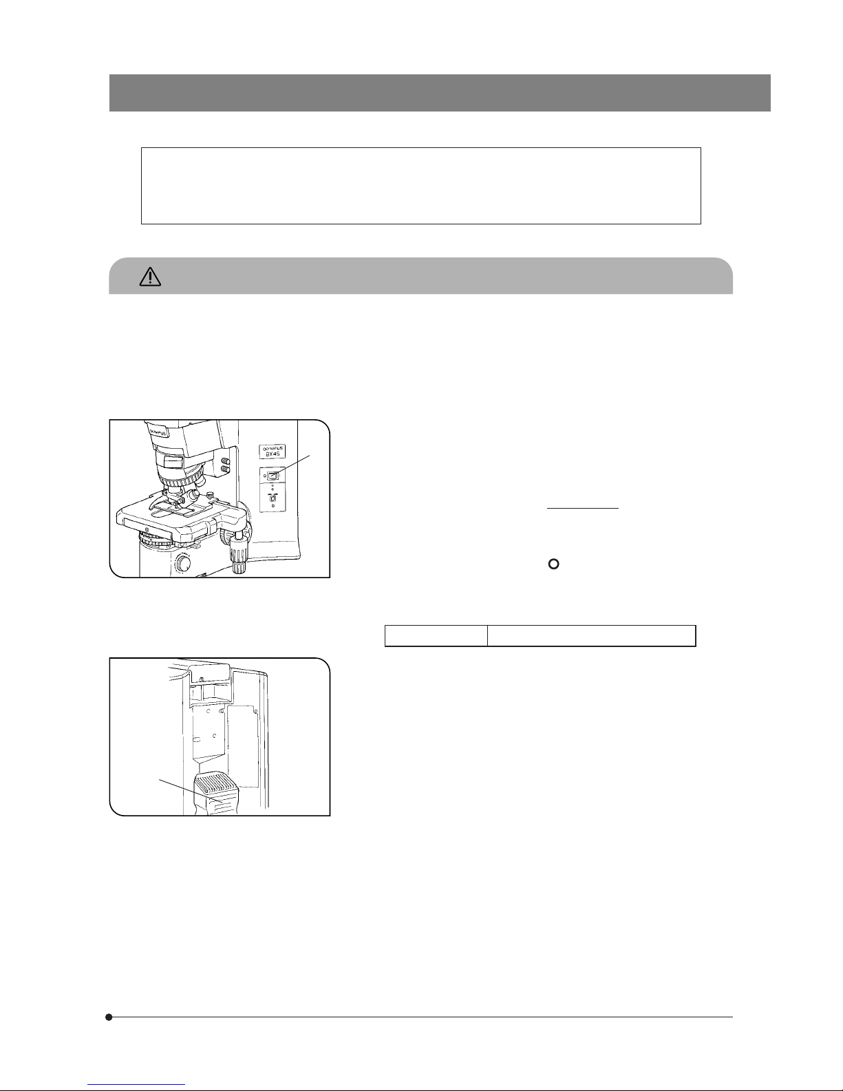
4. To avoid potential shock hazards and burns when replacing the light
bulb, set the main switch @ to “
” (OFF) then disconnect the power
cord from the wall outlet in advance. Whenever you replace the bulb
during use or right after use, allow the lamp socket ² and bulb to cool
before touching. (Figs 1 & 2)
IMPORTANT
SAFETY PRECAUTIONS
Fig. 1
Fig. 2
²
This microscope employs a UIS2/UIS (Universal Infinity System) optical design, and should be used only
with UIS2/UIS eyepieces, objectives and condensers for the BX2 series. (Some of the modules designed for
the BX series and objectives/eyepieces for the UIS series are also usable. For details, please consult Olympus
or the catalogues.) Less than optimum performance may result if inappropriate accessories are used.
Designated bulb
6V30WHAL (PHILIPS 5761)
# The microscope also incorporate a fuse (this should be replaced by
the manufacturer or authorized agent).
5. Always use the power cord provided by Olympus. If no power cord is
provided, please select the proper power cord by referring to the section
“PROPER SELECTION OF THE POWER SUPPLY CORD” at the end of
this instruction manual. If the proper power cord is not used, product
safety and performance cannot be guaranteed.
6. Always ensure that the grounding terminal of the microscope and that
of the wall outlet are properly connected. If the equipment is not
grounded/earthed, Olympus can no longer warrant the electrical safety
and performance of the equipment.
7. Never insert metallic objects into the air vents of the microscope frame
as this could result in electrical shock, personal injury and equipment
damage.
8. The power cord may be melt by the heat of lamp socket if the cord
comes in contact with it. Distribute the power cord at an enough distance from the lamp socket.
@
2
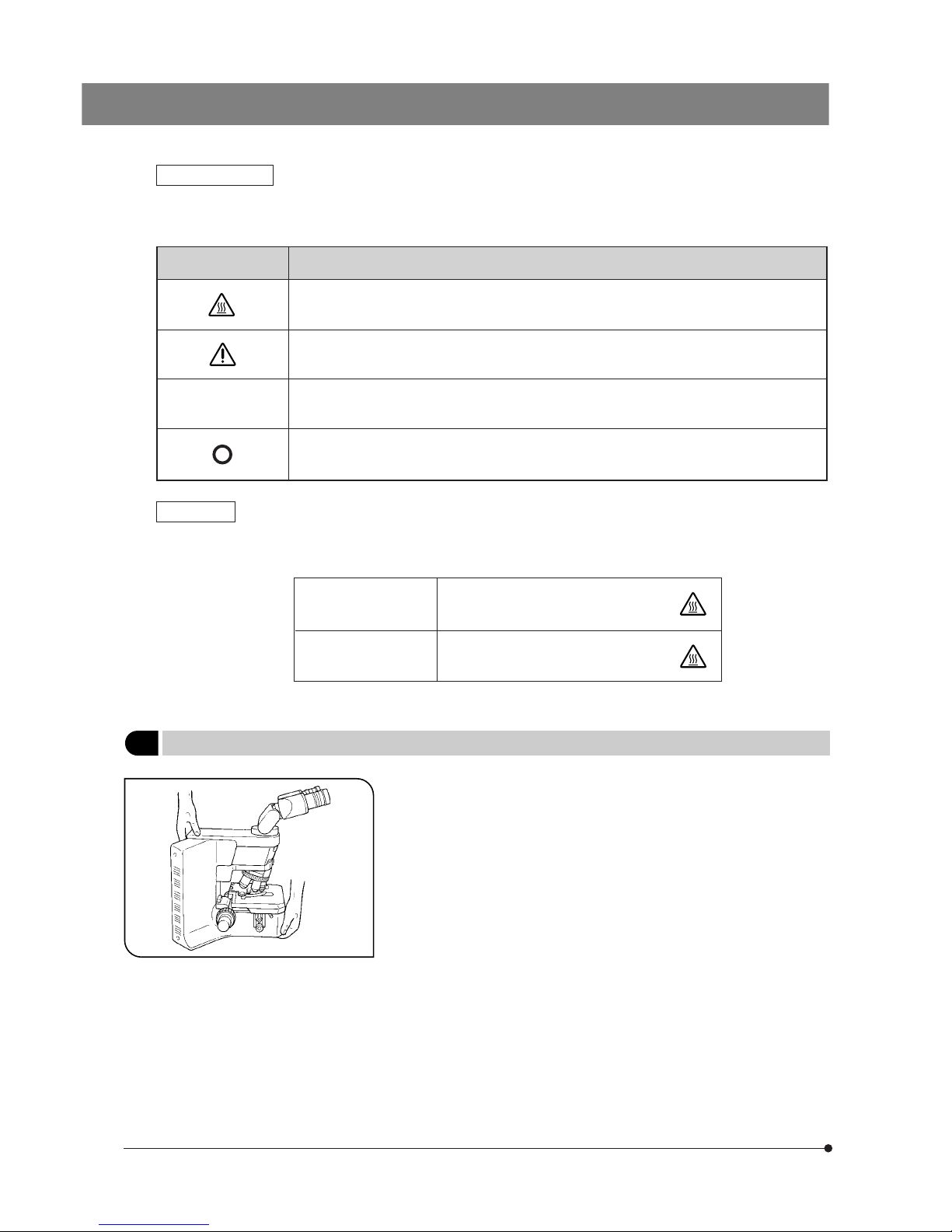
Symbol Explanation
l
Safety Symbols
Indicates that the surface becomes hot, and should not be touched with bare hands.
Before use, carefully read the instruction manual. Improper use could result in personal injury to
the user and/or damage to the equipment.
Indicates that the main switch is ON.
Indicates that the main switch is OFF.
Warnings
Warning engraving
position
Lamp socket
(Warning against high temperature)
Warning sticker
position
Microscope frame rear panel
(Warning against high temperature)
Fig. 3
1 Getting Ready
The following symbols are found on the microscope. Study the meaning of the symbols and always use the equipment in the safest possible manner.
Warning engraving/stickers are placed at parts where special precaution is required when handling and using the
microscope. Always heed the warnings.
Should warning stickers become soiled, peeled off, etc., contact Olympus for replacement.
1. A microscope is a precision instrument. Handle it with care and avoid
subjecting it to sudden or severe impact.
2. Do not use the microscope where it is subjected to direct sunlight, high
temperature and humidity, dust or vibrations. (For the operating conditions, refer to section 6, “SPECIFICATIONS”.)
3. When moving the microscope, remove the specimen and modules that
may drop during transport and carefully carry it with the grasping part
on the rear of the arm and the base as shown in Fig. 3 (Weight: approx.
14 k g ) .
# Damage to the microscope will occur if you grasp it by the stage,
coarse/fine adjustment knob or binocular section of the observation tube.
4. The BX45 can be used with only one intermediate attachment.

BX45
3
1. To clean the lenses and other glass components, simply blow dirty away using a commercially available blower and wipe
gently using a piece of cleaning paper (or clean gauze).
If a lens is stained with fingerprints or oil smudges, wipe it gauze slightly moistened with commercially available absolute
alcohol.
Since the absolute alcohol is highly flammable, it must be handled carefully.
Be sure to keep it away from open flames or potential sources of electrical sparks –– for example, electrical
equipment that is being switched on or off.
Also remember to always use it only in a well-ventilated room.
2. Do not attempt to use organic solvents to clean the microscope components other than the glass components. To clean
them, use a lint-free, soft cloth slightly moistened with a diluted neutral detergent.
3. Do not disassemble any part of the microscope as this could result in malfunction or reduced performance.
4. When not using the microscope, keep it covered with a dust cover.
5. When disposing of the microscope. Check the regulations and rules of your local government and be sure to
observe them.
2 Maintenance and Storage
NOTE: This equipment has been tested and found to comply with the limits for a Class A digital device,
pursuant to Part 15 of the FCC Rules. These limits are designed to provide reasonable protection
against harmful interference when the equipment is operated in a commercial environment. This
equipment generates, uses, and can radiate radio frequency energy and, if not installed and used in
accordance with the instruction manual, may cause harmful interference to radio communications.
Operation of this equipment in a residential area is likely to cause harmful interference in which case
the user will be required to correct the interference at his own expense.
FCC WARNING: Changes or modifications not expressly approved by the party responsible for compliance
could void the user’s authority to operate the equipment.
This device complies with the requirements of directive 98/79/EC concerning in vitro diagnostic
medical devices. CE marking means the conformity to the directive.
The following symbols are used to set off text in this instruction manual.
: Indicates that failure to follow the instructions in the warning could result in bodily harm to the
user and/or damage to equipment (including objects in the vicinity of the equipment).
# : Indicates that failure to follow the instructions could result in damage to equipment.
} : Indicates commentary (for ease of operation and maintenance).
3 Caution
If the microscope is used in a manner not specified by this manual, the safety of the user may be imperiled. In addition,
the equipment may also be damaged. Always use the equipment as outlined in this instruction manual.
4
1
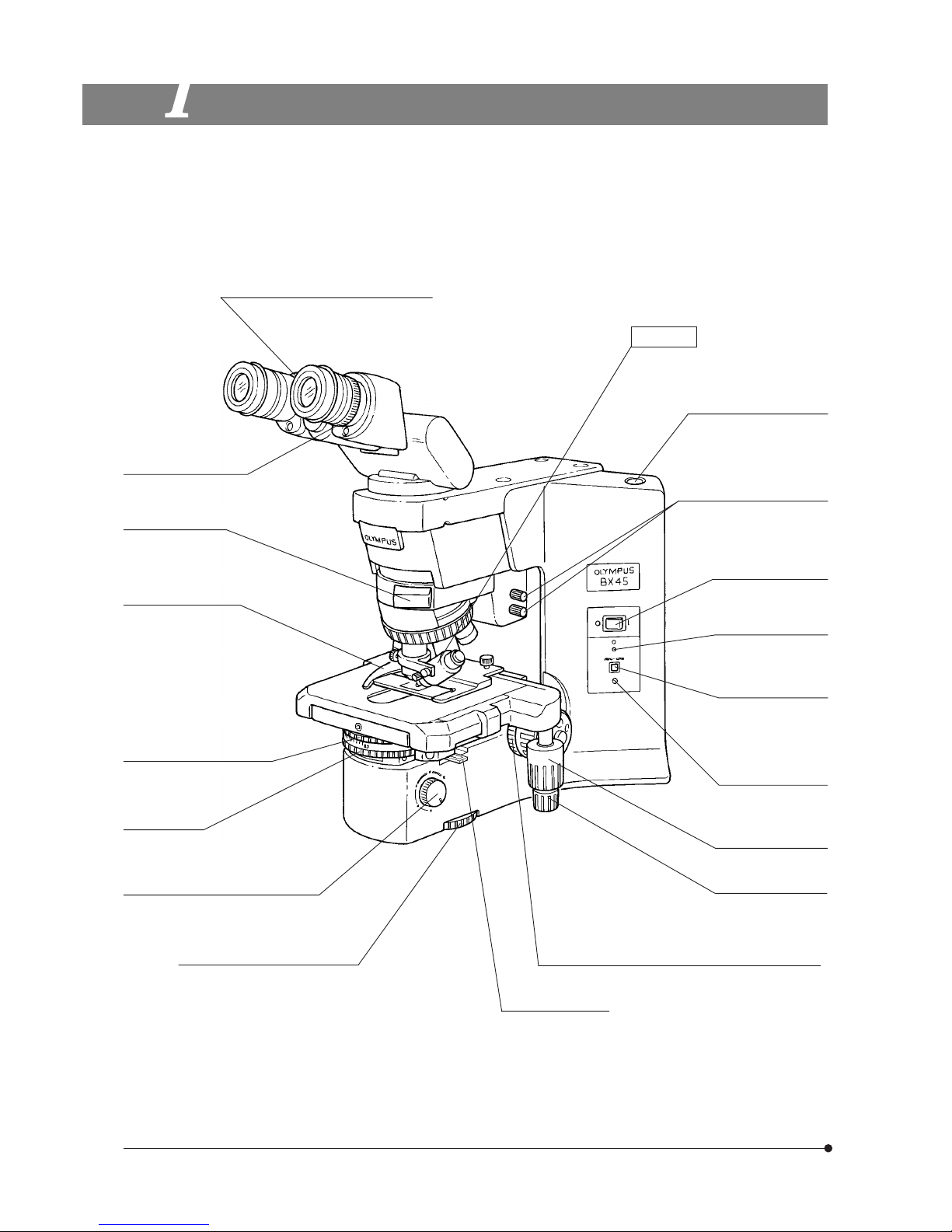
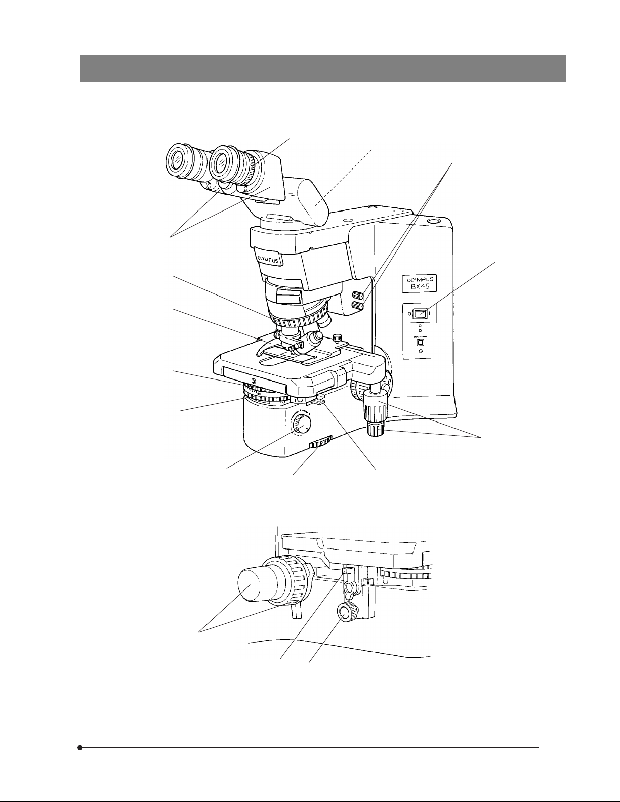
NOMENCLATURE
}If you have not yet assembled the microscope, read section 8, “ASSEMBLY” (pages 28 to 30).
Interpupillary distance adjustment scale
(Page 13)
Diopter adjustment ring
(Page 13)
Slider insertion slot
Slide holder (Page 11)
Aperture iris diaphragm ring
(Page 16)
Y-axis knob (Page 12)
X-axis knob (Page 12)
Turret (Page 5)
Brightness adjustment knob (Page 8)
(Lamp voltage adjustment knob)
Field iris diaphragm ring (Page 15)
Marker
U-MARKER
Allen screwdriver
(accommodation position)
Condenser centering screws
Main switch (Page 1)
Voltage indicator LED
Light intensity preset
switch (Page 8)
Light intensity preset
adjustment screw
(Page 8)
Coarse adjustment tension adjustment ring (Page 10)
Filter slider (Page 9)
(accommodation positions)
BX45
5
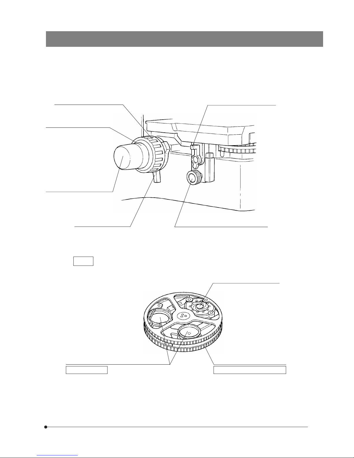
Coarse adjustment knob (Page 10)
Pre-focusing lever (Page 10)
Fine adjustment knob (Page 10)
(Detachable)
Fine adjustment knob rubber cap
(Page 10)
Top lens swing-out lever (Page 15)
Condenser height adjustment knob (Page 15)
Turret
View when disassembled from the microscope frame.
Aperture iris diaphragm (Page 16)
Filter mount (Bottom side) (Page 9)
Mountable filters (32 mm diameter)
· 32C (provided), (32LBD)*
· 32LND6
· 32LND25
· 32IF550
* Refer to Page 9 for precautions
on use.
Phase contrast/darkfield ring mount (Pages 18 - 20)
Mountable devices
Optical devices for phase contrast
· BX45-PH1
· BX45-PH2
· BX45-PH3
Optical devices for darkfield
· BX45-DFA
6
(Page)
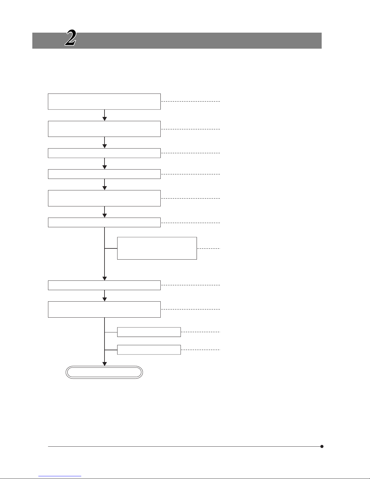
TRANSMITTED LIGHT BRIGHTFIELD OBSERVATION
PROCEDURE
}As the phase contrast, darkfield and simplified polarized light observations using transmitted light requires preparation using
optical devices such as an analyzer or polarizer, they will additionally be detailed in section 4, “OBSERVATION”.
Set the main switch to “ I ” (ON) and adjust the
brightness.
(Controls Used)
(P. 8)
@Main switch
²Brightness adjustment knob
Select the BF (brightfield) light path by turning
the turret.
³Turret
Select the light path (trinocular tube).
|Light path selector knob
Place the specimen on the stage.
ƒSlide holder
…X-/Y-axis knobs
Engage the 10X objective in the light path.
Then engage the top lens in the light path.
†Revolving nosepiece
‡Top lens swing-out lever
Bring the specimen in focus.
ŠCoarse/fine adjustment knobs
Adjust the interpupillary distance.
Adjust the diopter.
Adjust the light axis.
‰Binocular tube
‹Diopter adjustment ring
ŒCondenser height adjustment
knob
™Condenser centering screws
Adjust the aperture iris and field iris diaphragms.
šAperture iris diaphragm ring
›Field iris diaphragm ring
Engage the desired objective in the light path
and bring the specimen in focus.
†Revolving nosepiece
‡Top lens swing-out lever
Insert the required filters.
œFilters
Adjust the brightness.
²Brightness adjustment knob
Start observation.
(P. 11)
(P. 12)
(P. 15)
(P. 13)
(P. 13)
(P. 15)
(P. 15)
(P. 10)
(P. 9)
(P. 15)
(P. 16)
(P. 15)
(P. 8)
BX45
7
@
²
ƒ
œ
†
‡
Š
‰
‹
…
} Copy the observation procedure pages on separate sheets and post it near your microscope.
š
|
(Trinocular observation tube only)
³
›
™
Œ
8
USING THE CONTROLS
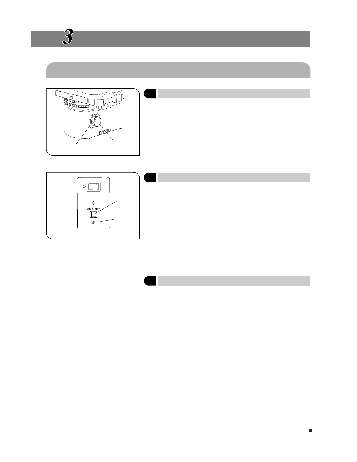
3-1 Base
Fig. 4
@
Fig. 5
@
²
²
1 Voltage Indication
(Fig. 4)
1. Turn the brightness adjustment knob @ clockwise to increase the voltage and make illumination brighter.
2. The numerals ² around the knob indicate the approximate voltage.
2 Using the Light Intensity Preset Switch
(Fig. 5)
}The light intensity preset switch @ makes it possible to limit the light
intensity to a preselected level regardless of the position of the brightness adjustment knob. The light intensity preset switch has been set to
about 4 V at the factory.
1. Press the light intensity preset switch @ to the ON position. (The face of
the switch lights when it is ON.)
2. Using a small flat-blade screwdriver, turn the preset adjustment screw ²
to obtain the required light intensity. Turning the screw clockwise increases
brightness.
3. When the light intensity preset switch is set to OFF, the brightness returns
to the level set by the brightness adjustment knob.
}While the light intensity preset switch is ON, turning the brightness ad-
justment knob does not affect brightness.
3 Using the Filters
(Figs. 6 - 8)
}You can place a filter in the light path with either method. (Only the 32C
daylight filter is provided with the microscope.)
· Place a 32 mm diameter filter on the filter slider and engage it in the light
path. (Page 9)
· Insert up to three 32 mm diameter filters on the bottom side of the turret
and turn to engage the filters in the light path. (Page 9)
 Loading...